NPTGCP2517B - Lawn mower LawnMaster - Free user manual and instructions
Find the device manual for free NPTGCP2517B LawnMaster in PDF.


| Product Type | 25cc 2-Cycle Grass Trimmer |
| Engine Displacement | 25 cc (25 cm³) |
| Power / Speed | 0.8 kW / 7500 RPM |
| Idle Speed | 3000 ± 300 RPM |
| Max Torque / Speed | 1.08 N·m / 6500 RPM |
| Fuel Tank Capacity | 420 ml |
| Fuel / Oil Ratio | 40:1 |
| Cutting Width | 17" (430 mm) |
| Cutting Line Diameter | 0.080" (2.0 mm) |
| Dry Weight | 11.68 lbs (5.3 kg) |
| Battery Type | 7.2V Lithium-Ion, 1.3 Ah (Model 7LB1331-C) |
| Charger Model | YLS0042-T084045 |
| Charger Input | 100-240V ~ 50/60Hz 0.3A Max |
| Charger Output | 8.4V — 450 mA |
| Charging Time (Fully Discharged) | 4-6 hours |
| Cutting Method | Bump-feed line advance |
| Shut-off Type | Stop switch (press to stop) |
| Warranty | 2 years (residential), 90 days (commercial); battery and charger: 2 years |
| Recommended Fuel | Unleaded gasoline with up to 10% ethanol (E10) |
| Assist Handle | Adjustable, with wing nut |
| Debris Guard | Included with cutting blade |
| Spark Plug Gap | 0.026" (0.65 mm) |
| Altitude Adjustment | Requires reconfiguration above 2000 ft |
Frequently Asked Questions - NPTGCP2517B LawnMaster
User questions about NPTGCP2517B LawnMaster
0 question about this device. Answer the ones you know or ask your own.
Ask a new question about this device
Download the instructions for your Lawn mower in PDF format for free! Find your manual NPTGCP2517B - LawnMaster and take your electronic device back in hand. On this page are published all the documents necessary for the use of your device. NPTGCP2517B by LawnMaster.
USER MANUAL NPTGCP2517B LawnMaster
natural_image
Technical line drawing of a mechanical device with articulated arm and base mount (no text or symbols)NOTICE:
Only use unleaded gasoline containing up to 10% ethanol. Do not use E15 or E85 fuel in this trimmer. It will violate the federal law, damage the trimmer and void your warranty.
AVISO:
Read all safety rules and instructions carefully before operating this tool.
601 Regent Park Court Greenville, SC 29607, SC 29650 1-866-384-8432

PRODUCT SPECIFICATIONS
25cc-2 CYCLE GRASS TRIMMER
| Engine Type | 2-Stroke / Half Crank |
| Engine Displacement Claimed / Rated | 25cc / 25 cm3 |
| Power / Speed | 0.8 kW / 7500 RPM |
| Idle Speed | 3000 ± 300 RPM |
| Max Torque / Speed | 1.08 N.m / 6500 RPM |
| Fuel Tank Capacity | 420 ml |
| Fuel / Oil Ratio | 40 : 1 |
| Line Diameter | 0.080" (2.0 mm) |
| Cutting Width | 17" (430 mm) |
| Dry Weight | 11.68 lbs (5.3 kg) |
| Battery Model No. | 7LB1331-C |
| Battery Type | 7.2V Lithium-Ion, 1.3 Ah |
| Charger Model No. | YLS0042-T084045 |
| Charger Input | 100-240V ~ 50/60Hz 0.3A Max |
| Charger Output | 8.4V---450 mA |
| Charging Period (Battery Fully Discharged) | 4-6 Hours |

WARNING
READ ALL INSTRUCTIONS AND SAVE THESE INSTRUCTIONS.
Read the Operator's Manual and follow all warnings and safety instructions. Failure to do so can result in serious injury to the operator and/or bystanders.
■ This grass trimmer is designed for cutting grass, soft vegetation.
■ The grass trimmer is intended for residential, or similar landscape use and is not recommended for use in agricultural or forest environments.
■ This grass trimmer is not suitable for cutting or chopping, otherwise, there is a risk of injury. For example:
- Hedges, shrubs and bushes,
- Flowers,
- In terms of composting.
■ Never allow children or persons unfamiliar with these instructions to use the trimmer.
■ Do not operate the trimmer inside a closed environment, such as a room or building; breathing carbon monoxide from exhaust fumes can kill.
- Clear the work area before each use. Remove all objects such as rocks, broken glass, nails, wire, or string, which can be thrown or become entangled in the cutting attachment.
- Clear the area of children, bystanders and pets. At a minimum, keep all children, bystanders and pets outside a 50 ft (15 m) radius; outside the 50 ft (15 m) zone, there is still a risk of injury from thrown objects.
■ Bystanders should be encouraged to wear eye protection. If you are approached, stop the engine and cutting attachment.
■ Always wear eye protection with side shields marked to comply with ANSI Z87.1 along with hearing protection when operating this trimmer. Failure to do so could result in objects being thrown into your eyes and other possible serious injuries.
■ Always wear heavy, long pants, boots, gloves, and a long-sleeve shirt. Do not wear loose clothing, jewelry, short pants, sandals, or go barefoot. Secure hair so it is above shoulder level.
■ Do not operate this trimmer when you are tired, ill, upset, or under the influence of alcohol, drugs, or medication.
- Inspect the trimmer before each use. Replace damaged parts. Check for fuel leaks. Make sure all fasteners are in place and secure.
■ Replace cutting attachment parts that are cracked, chipped, or damaged in any way. Make sure the cutting attachment is properly installed and securely fastened. Be sure the cutting attachment shield is properly attached, securely fastened and in the position recommended by the manufacturer.
■ Use only a flexible, nonmetallic line recommended by the manufacturer. Never use, for example, wire or wire-rope, which can break off and become a dangerous projectile.
■ Only use the grass trimmer in daylight or good artificial light.
■ Never operate the grass trimmer with damaged guards or without the guards in place.
- Maintain a firm grip on both handles while using this tool.
- Keep firm footing and balance. Do not overreach. Overreaching can result in loss of balance or exposure to hot surfaces.
- Maintain stable footing on a solid surface at all times when using the trimmer in order to have better control of the tool. Do not use the trimmer whilst on a ladder or other unstable support.
- Keep cutting attachment below waist level. Keep all parts of your body away from the rotating cutting attachment and hot surfaces.
■ Do not touch muffler, rear cover housing or casing around the engine; these parts get hot whilst and after the trimmer has been used. Contact with hot surfaces could result in serious burns.
■ The cutting attachment should never rotate at idle during normal use.
■ The cutting attachment may be spinning during carburetor adjustments. Wear your protective equipment and observe all safety instructions. For units equipped with a clutch, be sure the cutting attachment stops turning when the engine idles. When the unit is turned off, make sure the cutting attachment has stopped before the unit is set down.
■ Mix and store fuel in a container approved for storing gasoline.
- Mix and pour fuel outdoors where there are no sparks and flames. Slowly remove the fuel cap only after stopping the engine and letting it cool completely. Do not smoke while fueling or mixing fuel. Wipe spilled fuel from the trimmer. Move at least 10 ft (3 m) away from the fueling source and the site before starting engine.
■ Before fueling or storing the tool, stop the engine and allow it to cool completely.
■ Before transporting the tool in a vehicle, allow the engine to cool completely and empty the fuel tank. Always secure the tool to avoid movement during transportation.
- Only use replacement parts or accessories provided or listed in this Operator's Manual.
This trimmer is not intended for extended use. Extended periods of operation can cause circulatory problems in the user's hands due to the vibration caused by the tool. Take regular breaks from operating the tool.
■ Always take your tool to an authorized service center for repair. Service performed by inexperienced or unqualified persons may damage the tool, create unsafe conditions, increase the risk of personal injury, and/or void your warranty.
BATTERY PACK
■ The battery pack is compatible with the YLS0042-T084045 charger.
- Charge the battery only with the charger specified by the manufacturer and listed in this manual. A charger that is suitable for one type of battery pack may create a risk of fire when used with another battery pack.
■ Do not place battery powered tools or their batteries near fire or heat. This will reduce the risk of explosion and possibly injury.
■ Do not open or mutilate the battery pack. Released electrolyte is corrosive and may cause damage to the eyes or skin. It may be toxic if swallowed.
■ Do not dispose of battery packs in fire. They will explode or leak and cause injury. Liquid ejected from the battery may cause irritation or burns.
■ Do not crush, drop or damage the battery pack. Do not use a battery pack or charger that has been dropped or received a sharp blow. A damaged battery is subject to explosion. Properly dispose of a dropped or damaged battery immediately.
■ Batteries can explode in the presence of a source of ignition, such as a pilot light. To reduce the risk of serious personal injury, never use any cordless product in the presence of open flame. An exploded battery pack can propel debris and chemicals. If exposed, flush with water immediately.
■ Under extreme usage or temperature conditions, battery pack leakage may occur. If liquid comes in contact with your skin, wash immediately with soap and water, then neutralize with lemon juice or vinegar. If liquid gets into your eyes, flush them with clean water for at least 10 minutes, then seek immediate medical attention.
■ When the battery pack is not in use, keep it away from other metal objects like: paper clips, keys, nails, screws, or other small metal objects that can make a connection from one terminal to another. Shorting the battery pack terminals together may cause sparks, burns, or a fire.
■ Do not expose a battery pack to fire or excessive temperature. Exposure to fire or temperature above 265irc F ( 130irc C) may cause an explosion.
■ Do not modify or attempt to repair the battery pack (as applicable) except as indicated in the instructions for use and care.
■ Follow all charging instructions and do not charge the battery pack outside the temperature range specified in the instructions. Charging improperly or at temperatures outside of the specified range may damage the battery and increase the risk of fire.
BATTERY CHARGER
■ This charger is compatible with a 7LB1331-C or 07LB2001-S lithium-ion battery.
■ To reduce the risk of injury, charge only the specified lithium-ion rechargeable batteries. Other types of batteries may burst, causing personal injury or damage.
■ Do not charge the battery in a damp or wet location. Following this rule will reduce the risk of electric shock.
- Keep the cord and charger away from heat to prevent damage to housing or internal parts.
■ Do not operate charger with a damaged cord or plug, which could cause shorting and electric shock. If damaged, immediately discontinue use. Replace the charger with an identical model as listed in this manual.
■ Do not use a charger that has been dropped or received a sharp blow.
■ Do not disassemble charger. Take it to a qualified service center to be checked or replaced. Incorrect reassembly may result in a risk of electric shock or fire.
■ Do not abuse the charger cord. Never use the cord for carrying, pulling or unplugging.
- Keep the cord away from heat, oil, sharp edges or moving parts. Damaged or entangled cords increase the risk of electric shock. If the charger cord is damaged, replace the charger with an
identical model as listed in this manual.
■ A charger that is suitable for one type of battery pack may create a risk of fire when used with another battery pack.
■ Charge the battery at the normal charging temperature between 40irc F ( 4irc C) and 100irc F ( 38irc C).
FCC COMPLIANCE
■ This device complies with Part 15 of the FCC Rules. Operation is subject to the following two conditions:
- This device may not cause harmful interference, and
- This device must accept any interference received, including interference that may cause undesired operation.
NOTE: This equipment has been tested and found to comply with the limits for a Class B digital device, pursuant to Part 15 of the FCC Rules. These limits are designed to provide reasonable protection against harmful interference in a residential installation.
■ This equipment generates, uses and can radiate radio frequency energy and, if not installed and used in accordance with the instructions, may cause harmful interference to radio communications. However, there is no guarantee that interference will not occur in a particular installation. If this equipment does cause harmful interference to radio or television reception, which can be determined by turning the equipment off and on, the user is encouraged to try to correct the interference by one or more of the following measures:
- Reorient or relocate the receiving antenna.
- Increase the separation between the equipment and receiver.
- Connect the equipment into an outlet on a circuit different from that of the receiver.
- Consult the dealer or an experienced radio/ TV technician for help.

WARNING
The engine exhaust from this product can expose you to chemicals including carbon monoxide, which is known to the State of California to cause cancer, birth defects, or other reproductive harm. To reduce the risk of serious or fatal injury/illness, never run the machine indoors or in poorly ventilated locations. For more information go to www.P65Warnings.ca.gov.
SAVE THESE INSTRUCTIONS
Refer to them frequently and use them to instruct others who may use this product. If you loan someone this product, loan them these instructions also.
| Some of the following symbols may be used on this product. Please study them and learn their meaning. Proper interpretation of these symbols will allow you to operate the product better and safer. | ||
| SYMBOL | NAMEDESIGNATION/EXPLANATION | |
| V | Volts Voltage | |
| A | Amperes Current | |
| Hz | Hertz Frequency (cycles per second) | |
| W | Watt Power | |
| hrs | Hours Time | |
| /min | Per Minute | Revolutions, strokes, surface speed, orbits etc., per minute |
| no | No Load Speed Rational speed, at no load | |
| ~ | Alternating Current Type of current | |
| --- | Direct Current Type or a characteristic of current | |
| Lithium-Ion Battery Recycling | Designates that this tool is in compliance with Lithium-Ion battery recycling program requirements | |
 | Safety Alert | Precaution that involves your safety. |
 | Read the Operator's Manual | You must read the operating instructions carefully. |
 | Eye and Hearing Protection | Always wear eye protection with side shields marked to comply with ANSI Z87.1 along with hearing protection when operating this equipment. |
 | Gloves | Wear non-slip, heavy-duty protective gloves when handling this product. |
 | Safety Footwear | Wear non-slip safety footwear when using this product. |
 | Keep Bystanders Away Keep all bystanders at least 50' (15 m) away. | |
 | Ricochet | Thrown objects can ricochet and result in personal injury or property damage. |
 | No Blade | Do not install or use any type of blade on a product displaying this symbol. |
 | Gasoline and Lubricant | Use unleaded gasoline intended for motor vehicle use with an octane rating of 87 [(R + M) / 2] or higher. This product is powered by a 2-cycle engine and requires pre-mixing gasoline and 2-cycle lubricant. |
 | Keep Away From Water | Do not dispose of battery packs in rivers or immerse in water. |
 | Close | Close the choke. |
 | Open | Open the choke. |
 | Keep Away From Fire | Do not dispose of battery packs in fire. They will explode or leak and cause injury. |
 | Heat Alert | Do not expose battery packs to heat in excess of 140°F (60°C). |
 | Recycle Symbol | This product uses lithium-ion batteries. Local, state, or federal laws may prohibit disposal of batteries in ordinary trash. Consult your local waste authority for information regarding available recycling and/or disposal options. |
| The following signal words and meanings are intended to explain the levels of risk associated with this product. SYMBOLSIGNALMEANING | ||
 | DANGER | Indicates an imminently hazardous situation, which, if not avoided, will result in death or serious injury. |
 | WARNING | Indicates a potentially hazardous situation, which, if not avoided, could result in death or serious injury. |
 | CAUTION | Indicates a potentially hazardous situation, which, if not avoided, may result in minor or moderate injury. |
| NOTICE | (Without Safety Alert Symbol) Indicates a situation that may result in property damage. | |


The safe use of this product requires an understanding of the information on the product and in this Operator's Manual as well as knowledge of the project you are attempting. Before use of this product, familiarize yourself with all operating features and safety rules.
Components
- Choke Lever
- Primer Bulb
- Air Filter Cover
- Fuel Tank Cap
- Fuel Tank
- Main Handle
- Stop Switch
- Battery Slot
- Battery Release Button
- Locking Collar
- Shaft
- Debris Guard
- Trimmer Line
- Trimmer Head With Line Spool
- Assist Handle
- Start Button
- Battery Indicator
- Throttle Safety
- Engine Housing
- Spark Pulg Cap
- Start Button Cover
- Trimmer Line Cutting Blade
- Shaft Connection Sleeve
- Throttle Lever
- Muffler
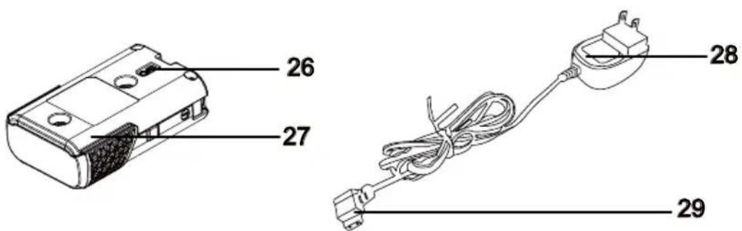
- Charging Port
- Battery Pack
- Charger
- Charging Connector
This product requires assembly.
- Carefully remove the product and any accessories from the box. Make sure that all items listed in the packing list are included.
■ Inspect the product carefully to make sure no breakage or damage occurred during shipping.
■ Do not discard the packing material until you have carefully inspected and satisfactorily operated the product.
■ If any parts are damaged or missing, please call the service center.
PACKING LIST
(1) Trimmer Assembly
(1) Assistant Handle (with screw and wing nut pre-installed)
(1) Curved Shaft Attachment (with trimmer head, line spool installed)
(1) Debris Guard (with one screw pre-installed)
(1) Socket Wrench / Cross-head Screwdriver
(1) Hex Wrench
(1) Quincunx Wrench
(1) Operator's Manual
(1) 7.2V Lithium-Ion 1.3 Ah Battery Pack
(1) Battery Charger

WARNING
If any parts are damaged or missing do not operate this product until the parts are replaced. Use of this product with damaged or missing parts could result in serious personal injury.

WARNING
Do not attempt to modify this product or create accessories not recommended for use with this product. Any such alteration or modification is misuse and could result in a hazardous condition leading to possible serious personal injury.

WARNING
To prevent accidental starting that could cause serious personal injury, always remove the battery pack from the product when assembling parts.
FITTING THE DEBRIS GUARD (See Figs. 1-3)

WARNING
The trimming line cutting blade on the debris guard is sharp and is fitted with a blade protection film which will need to be removed prior to using the trimmer. When fitting the guard avoid contact with the blade. Failure to avoid contact can result in serious personal injury.
■ Loosen and remove the screw from the debris guard using the screwdriver provided.
■ Starting from the top of the split shaft, slide the debris guard all the way down to the correct mounting position as shown (Fig. 1).
■ Align the screw hole on the debris guard with the screw hole on the bracket. Insert the screw through the debris guard and the bracket on the shaft (Fig. 2).
■ Secure the screw tight using the screwdrive (Fig. 3).

natural_image
Diagram of a robotic arm with curved arm and base, showing motion direction (no text or symbols)

natural_image
Technical line drawing of a mechanical assembly with a central component and base mount (no text or symbols)Fig. 1 Fig. 2
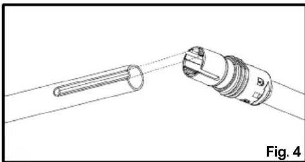
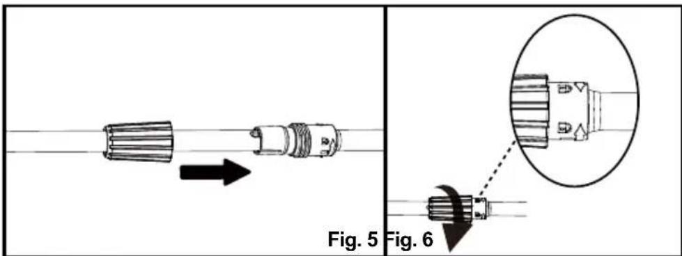
INSTALLING AND REMOVING THE SHAFT (See Figs. 4-6)

WARNING
Never install, remove, or adjust any attachment while the engine is running. Failure to stop the engine can cause serious personal injury.
To install the shaft:
■ Turn the locking collar counter-clockwise to remove it from the shaft connection sleeve. Slide the locking collar onto the shaft.
■ Check to ensure the axles in the shafts are aligned as shown (Fig. 4). If not aligned, slightly rotate the trimmer head to adjust the axle until it aligns.
natural_image
Technical line drawing of a mechanical component with a threaded shaft and connector, labeled Fig. 4 (no text or symbols on the diagram itself)■ Slide the shaft into the shaft connection sleeve, then slide the locking collar onto the connection sleeve to lock into place (Fig. 5).
■ Secure the shaft by turning the locking collar clockwise (Fig. 6).

WARNING
Ensure that the locking collar is fully tightened before operating the tool; check it periodically for tightness during use to avoid serious personal injury.
To remove the shaft:
■ Stop the engine and remove the battery pack.
■ Loosen the locking collar by turning counter-clockwise, and pull away from the connection sleeve.
■ Pull out the shaft to remove.
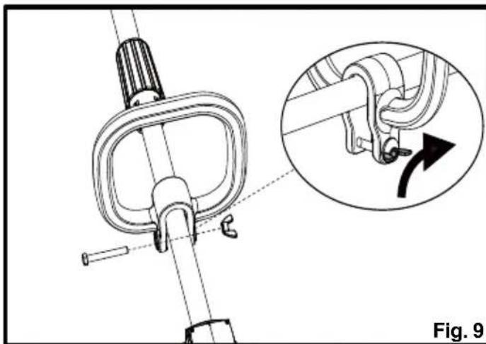
INSTALLING AND ADJUSTING THE ASSIST HANDLE (See Figs. 7-10)

WARNING
Never adjust the assist handle while the trimmer head is running. Failure to stop the engine may cause serious personal injury.
■ Loosen and remove the screw bolt and wing nut.
■ Fix the assist handle onto the shaft as shown by firmly pushing the handle onto the shaft. Make sure that the groove side faces the engine (Fig. 7).
■ Adjust the assist handle to your desired position. The assist handle can only be moved in the direction between the arrow marked "Handle Position" and shaft connection sleeve (Fig. 8).

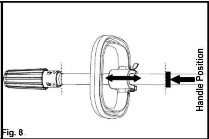
■ Insert the screw bolt to the screw holes on the assist handle and tighten the wing nut. Secure the wing nut tightly by turning it clockwise (Fig. 9).
■ Pay attention not to position the assist handle under the shaft (Fig. 10).
natural_image
Mechanical assembly diagram showing a clamping mechanism with an inset view of a rotating component (no text or symbols)
INSTALLING AND REMOVING THE BATTERY PACK (See Figs. 11-12)
To install the battery pack:
■ Align the battery pack with the battery slot.
■ Insert the battery pack into the battery slot until the battery pack secures into place. Make sure the battery is inserted in the correct direction (Fig. 11).
■ Do not use force when inserting the battery pack. It should slide into position and "click".
To remove the battery pack:
■ Press and hold the battery release button (Fig. 12).
■ Slide the battery pack from the battery slot.

BATTERY CHARGING
■ Use with 8.4V LawnMaster® YLS0042-T084045 battery charger. The battery charger supplied is specifically designed for the lithium-ion battery used in this tool.
■ Check the power voltage! Battery chargers operate on 100-240V AC.
- Charge the battery between 40°F (4°C) and 100°F (38°C) to ensure an optimum battery service life.
■ Protect the battery from heat, from continuous exposure to sun, and keep away from radiation or other heat sources. Do not leave the battery in the tool in direct sunlight over long periods.
■ The battery is supplied uncharged. Fully charge the battery before using the tool for the first time. The lithium-ion battery can be charged at any time without reducing its service life. Interrupting the charging procedure does not affect the battery.
CHARGER LEDS
■ If the battery is not connected to the charger, a continuous green LED light indicates that the plug is plugged into an outlet socket and the battery charger is ready for operation.
■ Charging: a continuous red LED on the charger indicates that the battery is charging normally.
■ Charged: a continuous green LED on the charger indicates that the battery is ready for use.
| INDICATOR LIGHTS STATUS | |
| Green, continuous | Fully charged / Connected to power supply (Standby) |
| Red, continuous Charging | |
■ After continuous or repeated charging cycles without interruption, the charger may warm up. This is normal and does not indicate a technical defect of the battery charger.
CHARGING THE BATTERY PACK (See Figs. 13-14)

WARNING
If any part of the charger is missing or damaged, do not operate it! Replace the charger with a new one. Failure to heed this warning could result in possible serious injury.
Check the voltage! The voltage must comply with the information on the rating label.
BATTERY PACK AND CHARGER
■ Insert the charging connector into the charging port on the battery (Fig. 13).
■ Connect the charger to the power supply.
- Allow sufficient charging time (see Product Specifications), and then disconnect the charger from the power supply.
■ Remove the charging connector from the charging port (Fig. 14).

natural_image
Technical line drawing of a device housing with a black arrow pointing to a component (no text or symbols present)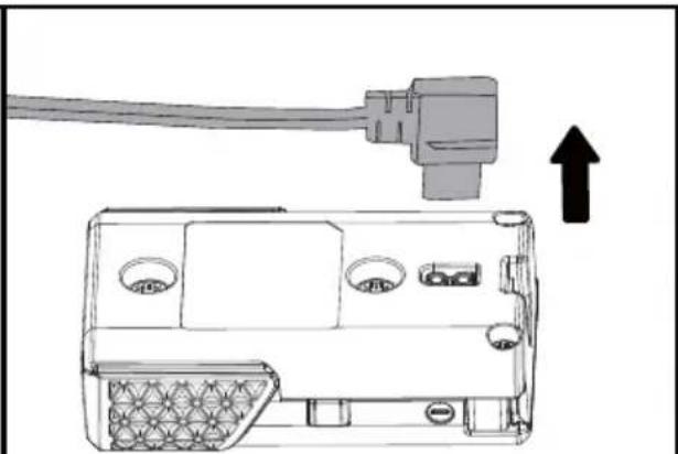
natural_image
Diagram of an electronic device showing a cable connected to a port, with an arrow indicating upward motion (no text or symbols present)Fig. 13 Fig. 14
NOTE: It is normal for the battery pack and the charger to become warm (but not hot) during the charging process. If the battery does not charge properly, check to make sure the electrical outlet is operational. Always charge the battery before storage!

WARNING
Do not allow familiarity with products to make you careless. Remember that a careless fraction of a second is sufficient to inflict serious injury.

WARNING
Always wear eye protection with side shields marked to comply with ANSI Z87.1, along with head protection. Failure to do so could result in objects being thrown into your eyes and other possible serious injuries.

WARNING
Do not use any attachments or accessories not recommended by the manufacturer or retailer of this product. The use of attachments or accessories not recommended can result in serious personal injury. Before each use, inspect the entire product for damaged, missing, or loose parts such as screws, nuts, bolts, caps, etc. Tighten securely all fasteners and caps and do not operate this product until all missing or damaged parts are replaced.
HANDLING THE FUEL

DANGER
The fuel is VERY flammable. Use extreme care when mixing, storing or handling, or serious personal injury may result.
■ Mix and store in a container approved for storing fuel.
■ DO NOT smoke when handling or close to fuel.
■ DO NOT allow flames or sparks near the fuel.
■ Maintain the pressure in the fuel tank; always loosen the fuel tank cap slowly allowing the pressure to equalize. NEVER refuel a trimmer when the engine is HOT or RUNNING!
■ DO NOT fill fuel tanks indoors. ALWAYS fill fuel tanks outdoors over bare ground.
■ DO NOT overfill the fuel tank and clean up spills immediately.
- Securely tighten the fuel tank cap and close the fuel container after refueling.
■ Check for fuel leakages. If a fuel leakage is present, remove the battery and do not use the
trimmer until the leakage is repaired.
■ Move at least 10 ft (3 m) from refueling location before starting the engine.
FUEL MIXTURE (See Fig. 15)
This trimmer is powered by a 2-cycle engine; the operator is required to use premixed gasoline and 2-cycle lubricant. Prepare a mixture of unleaded gasoline and 2-cycle engine lubricant in a clean container approved for storing gasoline. Only prepare quantities that can be used up within a few days. DO NOT prepare quantities that will need to be stored for more than 30 days.
Recommended Fuel
This engine is certified to operate on unleaded gasoline intended for automotive use.
U.S. EPA regulations make it illegal to use gasoline containing higher than 10% ethanol content in outdoor power equipment like your LawnMaster ® power equipment and doing so can void your LawnMaster ® Limited Warranty.
If the proper precautions are taken, however, gasoline containing a 10% quantity of ethanol can safely be used in your LawnMaster ® products.
Much of the gasoline sold throughout the United States contains ethanol. The maximum ethanol content allowed by law for use in outdoor power equipment is limited to 10% (E10). Most small power equipment engines are designed to use no more than a 10% ethanol gasoline blend.
If you are not sure of the ethanol content in the gasoline you are purchasing, ask the retailer. If they are unsure, purchase your fuel from another retailer that offers gasoline with no more than 10% ethanol.
NOTE: We recommend you use a high-quality synthetic 2-cycle lubricant in this product.
Recommended specification: JASO-FC or above. Mix at 40:1 ratio or 3.2 oz. per gallon (US).
Do not use automotive lubricant or 2-cycle outboard lubricant.
| Gasoline to Lubricant Mix - 40 : 1 Ratio | ||
 | GASOLINE LUBRICANT | |
| 1.0 gal. (US) (3.8 liter) 3. | 2 oz. (95 ml) | |
| 2.5 gal. (US) (9.5 liter) 8. | 0 oz. (236 ml) | |
Mixing Tips
■ Always start by filling an approved fuel container with half of the required amount of gasoline.
■ Then add the entire amount of 2-cycle lubricant. Close the container and shake to mix the lubricant with the gasoline.
■ Add the remaining amount of gasoline, close the fuel container, and shake again.
■ Ensure that the fuel is well mixed by shaking the container before filling the fuel tank (Fig. 15).

FILLING THE FUEL TANK (See Fig. 16)
NOTICE: Before each use, ALWAYS shake the fuel container thoroughly to ensure that the fuel is mixed completely.
■ Place the tool on a flat, level surface, outdoors. Ensure the fuel tank and the shaft are in the same level so enough fuel can be filled into the fuel tank.
■ Clean the area around the fuel tank and cap to prevent any contamination.
■ Loosen the fuel tank cap by turning it counter-clockwise and remove (Fig. 16).
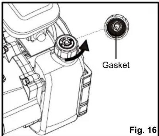
■ Carefully pour the fuel into the fuel tank, avoiding any spillage. Clean and check the gasket before replacing the cap onto the fuel tank.
■ DO NOT leave the fuel tank unsealed while it contains fuel. Replace the cap immediately after filling and inspecting the tank. Check that the cap is sealed tightly and wipe clean any spillage that may have occurred.
NOTICE: It is normal for smoke to be emitted from a new engine after first use.

WARNING
The operation of this tool requires gasoline, an extremely flammable liquid. Always turn off the engine and allow it to cool completely before fueling. Never remove the fuel tank cap or add the fuel to the tool while it is running or the engine is still hot. Make sure to fuel the tool outdoors on a flat, level surface. After fueling, immediately replace the fuel tank cap and tighten it securely. DO NOT fill the fuel tank on the work site; fueling must occur at least 10 ft. (3m) from where the operator intends to start the engine. Keep the tool away from smoke, open flames and sparks! Failure to follow these instructions could result in an explosion, fire and cause serious personal injury.
STARTING AND STOPPING THE GRASS TRIMMER (See Figs. 17-23)
For cold start:
■ Make sure that the battery pack is securely in place.
■ Place the trimmer on a levelled surface, outdoors.
■ Press the primer bulb 5 times or until the bulb fills with fuel.
■ Turn the choke lever to the CHOKE position (Fig. 17).

■ Lift the start button cover, press the start button and keep pressed until the engine starts. Manually turn the choke lever to the RUN position. For best results, let the engine warm up at idle for at least 1 minute, or lightly engage the throttle to speed up the process. Engaging the throttle fully before the trimmer is warm can cause the engine to stall (Fig. 18 - 20).
■ To begin trimming, engage the throttle safety and the throttle lever. Do not engage the throttle while pressing the start button (Fig. 21-22).

natural_image
Technical line drawing of a mechanical component with an arrow indicating rotation (no text or symbols)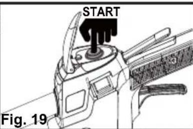

natural_image
Technical line drawing of a mechanical device with directional arrows and a circular symbol (no text or labels)
natural_image
Technical line drawing of a vehicle's front engine compartment with no visible text or symbolsFig. 20 Fig. 21 Fig.
■ If the choke lever is left on choke, the grass trimmer will stop running in 15-30 seconds.
NOTE: If the engine does not start, manually turn the choke lever to the RUN position, and hold the start button down until the engine starts.
■ If the trimmer fails to start, refer to the Troubleshooting section on pages 35.
For warm start:
■ Make sure that the battery pack is securely in place.
■ Place the trimmer on a levelled surface, outdoors.
■ Press the primer bulb 5 times or until the bulb fills with fuel.
■ Make sure the choke lever in the RUN position.
■ Lift the start button cover, press the start button and keep pressed until the engine starts. Then engage the throttle safety and the throttle lever to start the trimmer.
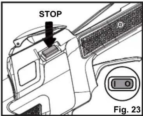
To stop the trimmer: Press the STOP switch to the stop position "O" until the trimmer stops (Fig. 23).
BATTERY POWER INDICATOR (See Fig. 24)
A battery power indicator is located above the start button, and can be used to indicate the battery status (Fig. 24).
When pushing the start button to start the engine, a green light indicates a fully charged battery; a red light indicates the battery needs to be charged.

HINT FOR OPTIMUM USE
In order to achieve optimum cutting results, only cut dry grass.
TRIMMING (See Fig. 25)

WARNING
The engine housing can become hot when the trimmer is being used. Do not make contact with this part of the tool during use and whilst it is still hot. When holding the trimmer, ensure all body parts are clear of the engine housing. Contact with this part can result in burns or other serious injuries.

WARNING
Always position the trimmer on your right side in order to reduce exposure to hot surfaces which can cause possible serious injuries.

WARNING
Keep the bottom of the engine below waist level during operation to avoid burns from hot surfaces.
■ Hold the grass trimmer firmly with both hands, keeping your right hand on the main handle and left hand on the assist handle.
■ The trimmer should be held at a comfortable position with the rear handle at waist level (Fig. 25).

natural_image
Line drawing of a person using a manual lawn power tool to clean grass, labeled Fig. 25 (no text on diagram)-
Keep your balance with your feet apart.
■ Always operate the trimmer in RUN position. When cutting long grass, work in stages from top to bottom in small sections. This will prevent the grass being cut from wrapping around the shaft and the spool head. -
Hold the grass trimmer head at an angle of approximately 30irc to the ground. Avoid pressing it against the ground as this can ruin the lawn and damage the product.
- Stop the engine if the grass becomes wrapped around the trimmer head and remove the grass once the cutting attachment has stopped rotating.
■ Extended use of the tool at partial throttle will result in lubricant dripping from the muffler.
TRIMMING TIPS (See Figs. 25-26)
- Keep the tool to the right side and away from your body to avoid making contact with the hot surfaces (Fig. 25).
- Keep the trimmer head lowered, towards the area being cut.
■ The curved shaft trimmer cuts best when moving the unit from right to left. Passing the tool in this direction will reduce the amount of debris thrown towards the operator. Avoid cutting in the dangerous area as shown (Fig. 26).
■ Use the tip of line to do the cutting; do not force the trimmer head into uncut grass.
■ The line can wear quickly and even break when used against solid surfaces such as fences, borders, curbs and walls made of metal, wood, stone and brick. Avoid using the trimmer against these materials.

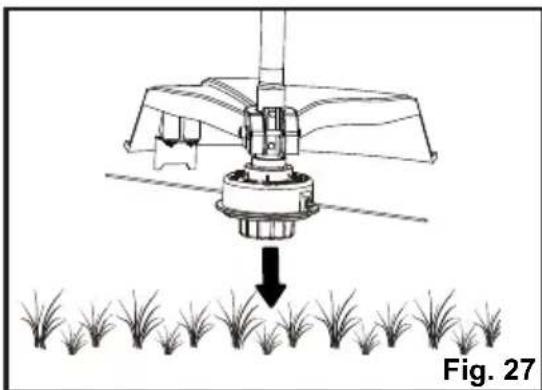
ADVANCING LINE (See Fig. 27)
This trimmer uses a line advance system which requires the operator to tap or bump the trimmer head on the grass while running the engine at full throttle.
■ Run the engine at full throttle.
■ Tap the trimmer head on the ground to advance the line. With each tap, the line advances further. A firm but gentle motion should be used when tapping the line on the ground (Fig. 27). DO NOT keep the trimmer head pressed against the ground.
NOTICE: The cutting blade on the underside of the debris guard will cut the line to the correct length.
NOTICE: Line that is too short may not advance using the tapping method and may need to be done manually.
natural_image
Diagram of a sprinkler system with a downward arrow indicating input or discharge, and a row of grass below (no text or symbols)To advance the cutting line manually:
■ Stop the engine completely.
■ Push the spool cover in while pulling on the line, until you reach the desired length.
NOTE: After each use, clean the trimmer head with a damp cloth to remove dirt and grime.
CUTTING BLADE (See Fig. 28)
The trimming line cutting blade is attached to the underside of the debris guard (Fig. 28).
The cutting blade trims the line at a length that yields optimum cutting results. If the engine is running faster than normal, or it appears as though the trimmer is less efficient, advance the line. This will maintain proper performance and keep the line long enough to efficiently cut the grass.

Normal maintenance, replacement or repair of emission control devices and systems may be performed by an authorized service center or qualified individual that uses identical parts. Warranty repairs must be performed by an authorized service center; please contact your service dealer for assistance or Customer Service (Toll Free Number 866-384-8432).

WARNING
When servicing, use only identical replacement parts. Use of any other parts may create a hazard or cause product damage.

WARNING
Before inspecting, cleaning, or servicing the machine, shut off the engine, wait for all moving parts to stop, and remove the battery pack. Failure to follow these instructions can result in serious personal injury or property damage.

WARNING
Always wear eye protection with side shields marked to comply with ANSI Z87.1, along with head protection. Failure to do so could result in objects being thrown into your eyes and other possible serious injuries.
NOTICE: Occasionally inspect the tool for damaged, missing, or loose parts such as screws, nuts, bolts, caps, etc. Do not operate this tool if parts are damaged or missing. Secure all fasteners and caps prior to using the tool. Please contact your service dealer for assistance or Customer Service (Toll Free Number 866-384-8432).
GENERAL MAINTENANCE
Avoid using solvents when cleaning plastic parts. Most plastics are susceptible to damage from various types of commercial solvents and may be damaged by their use. Use clean, dry cloths to remove dirt, dust, oil, grease, etc.
Keep all safety devices, air vents, and the motor housing free of dirt and dust.
Regularly clean the ventilation slot in your grass trimmer using a soft brush or dry cloth.
Regularly clean the cutting line and spool using a soft brush or dry cloth.
Regularly remove grass and dirt from the underside of the guard using a blunt scraper.

WARNING
Do not at any time let brake fluids, gasoline, petroleum-based products, penetrating lubricants, etc., come in contact with plastic parts. Chemicals can damage, weaken or destroy plastic which could result in serious personal injury.
BATTERY MAINTENANCE
■ Store the battery pack fully charged.
■ Do not allow the battery pack to become completely discharged.
■ Once the battery pack is fully charged, disconnect the charger from the outlet and remove the battery from the charger.
■ Do not store the battery pack on the tool or on the charger.
- Charge the battery at a temperature between 40°F (4°C) and 100°F (38°C). If the battery pack is hot, allow it to cool down before charging.
Storing the battery for 30 days or longer:
If the lithium-ion battery is being stored for 30 days or longer, store the battery pack in a location where the temperature does not exceed 80ircF (26°C) and is free of moisture.
- Store the battery pack in a 30%-50% charged condition.
- Fully charge the battery back every six months.
- The exterior part of the battery pack may be cleaned with a cloth or soft non-metallic brush.
CHARGER MAINTENANCE
- Keep the charger clean and clear of debris. Do not allow foreign material into the recessed cavity or on the contacts. Wipe with a dry cloth. Do not use solvents, water, or place in wet conditions.
■ Always unplug the charger when the battery pack is not installed on the charger. - Keep the charger stored at normal room temperature. Do not store it in excessive heat. Do not use in direct sunlight.
■ Disconnect the charger from the AC power outlet when not in use and once the battery has reached a full charge.
SPOOL REPLACEMENT (See Figs. 29-32)
■ Stop the engine and remove the battery pack.
■ Hold the main spool cover, and turn the spool head counter-clockwise to remove. Then remove the main spool cover together with the spool from the grass trimmer (Fig. 29).
■ Remove the empty spool from the spool cover. Then remove the spring (Fig. 30).

natural_image
Three-step mechanical assembly diagram showing a rotary knob, a central knob with arrows indicating rotation, and a final component with an arrow (no text or symbols)
natural_image
Mechanical assembly diagram showing two stages of a spring-loaded component with directional arrows indicating motion (no text or symbols)■ Refer to the Line Replacement section in this manual if only the line needs to be replaced.
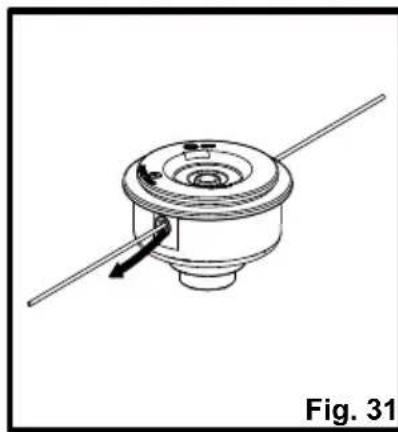
■ Install the spring to the new spool. Insert the new spool with spring into the spool cover. Release both trimming lines from the parking slot and guide the lines into both eyelets (Fig. 31).
■ Install the whole main spool cover back to the grass trimmer. Hold the main spool cover, install the spool head onto the main spool cover, and turn clockwise to secure it (Fig. 32).
natural_image
Technical line drawing of a mechanical component with a rotating shaft and housing (no text or symbols)
natural_image
Mechanical assembly diagram showing two stages of a valve mechanism with directional arrows (no text or symbols)LINE REPLACEMENT (See Figs. 33-35)
■ You may wind new cutting lines onto an empty spool.
■ Replacement cutting line is available from a DIY store or online.
■ Remove the empty spool from the grass trimmer as described above.
■ Remove any remaining cutting line from the spool.
NOTE: Use only round monofilament line with the recommended diameter.
■ Ensure that the new cutting line is sufficiently long, approximately 13 ft (4 m). Fold the line in half and then adjust it so that one end is approximately 3.5 in. (9 cm) longer than the other (Fig. 33).

natural_image
Technical line drawing of a mechanical gear assembly with no visible text or symbols■ Hook the folded end of the cutting line onto either of the slots in the spool (Fig. 34).
■ Wind the line onto the spool. Wind the line in the "Wind Cord" arrow direction indicated on the spool (Fig. 34).
■ Place the ends of the line in the two opposite parking slots of the spool, leaving some of the line out (Fig. 35).

NOTE: Always clean the main spool cover and trimmer head housing before reassembling the trimmer head.
NOTE: Always clean the trimmer head before replacing the spool.
- Check the spool cover, spool and spool head for wear and replace parts if necessary. Install the spool in the spool cover and replace as described in the Spool Replacement section.
NOTE: Only use the appropriate cutting line specified in this manual.
TRIMMER HEAD REPLACEMENT (See Fig. 36-37)
■ Stop the engine and remove the battery pack.
■ Place the trimmer on a flat stable surface with the trimmer head facing upward.
■ Remove the spool head and the main spool cover as described in the Spool replacement section.
■ To install the new trimmer head as shown in Fig. 36, firstly install the main spool cover with the spool and spring inside; then hold the whole main spool cover and rotate the spool head clockwise to secure it (Fig. 37).

CLEANING THE EXHAUST PORT, MUFFLER AND SPARK ARRESTOR
NOTICE:
The spark arrestor on this product has not been evaluated by the USDA Forest Service and cannot be used on U.S. forest lands. In addition, product users must comply with Federal, State, and local fire prevention regulations. Check with appropriate authorities. Contact Customer Service or your authorized service center to purchase a replacement spark arrestor.
If the trimmer appears less efficient or powerful, it may be due to the build-up of carbon deposits around the exhaust port and muffler. This may occur depending on the type of fuel used, the type and amount of lubricant used, or the operating conditions. In order to restore performance, take the trimmer to an authorized service center or qualified individual to remove the blockage.
The spark arrestor must be cleaned or replaced every 50 hours or yearly to ensure proper performance of your product. Spark arrestors may be in different locations depending on the model purchased. Please contact your nearest service dealer for the location of the spark arrestor for your model.
IDLE SPEED ADJUSTMENT

WARNING
The trimmer head will move when adjusting the idle speed. Wear protective clothing and keep all bystanders, children, and pets at least 50 ft. (15 m) away. Keep the trimmer off the ground and away from any objects when making adjustments. Keep all parts of your body away from the trimmer head and muffler. Failure to follow these instructions could result in serious personal injury.
The cutting attachment should never turn at idle. If the cutting attachment moves at idle speed, discontinue use immediately and contact an authorized service center to have the tool repaired. Serious personal injury could result from the cutting attachment turning at idle.
CLEANING THE AIR FILTER (See Figs. 38-41)
Keep the air filter clean for proper performance and long life.
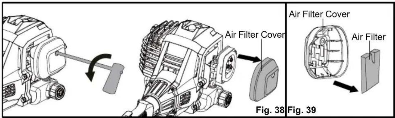
■ Loosen the screw to remove the air filter cover (Fig. 38).
■ Remove the air filter from the air filter cover (Fig. 39).
NOTE: Inspect the filter for damage and replace with a new filter if necessary.
■ Clean the foam filter with warm soapy water and rinse. Air dry the filter.
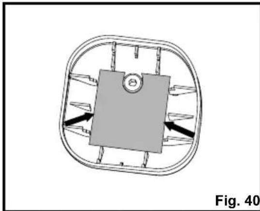
■ Place the air filter back, ensuring that it properly seated onto the air filter cover. Installing the filter correctly will decrease the chances of engine wear caused by dirt entering the engine (Fig. 40).
■ Replace the air filter cover ensuring the air filter is completely covered (Fig. 41).
■ Turn the screw clockwise to secure the air filter cover.
natural_image
Diagram of a mechanical or electrical component with directional arrows, no visible text or symbols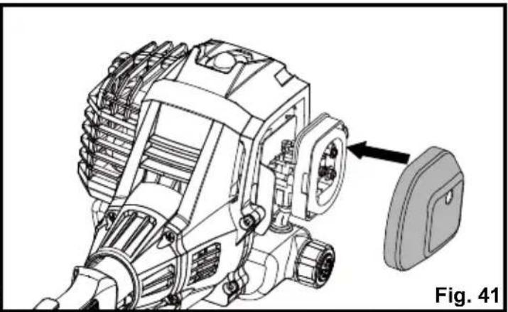
natural_image
Technical line drawing of an engine component with a close-up view of the internal gear assembly (no text or symbols)FUEL TANK CAP, TANK AND LINES

DANGER
Fuel is EXTREMELY flammable. Be very cautious and use care when mixing storing or handling. Failure to follow this instruction may lead to serious personal injury.

WARNING
Check for fuel leaks. Do not use the trimmer in the presence of a leak as it is a fire hazard. Loose or damaged tank caps, or leaking tanks must be replaced immediately. Failure to follow this instruction may lead to serious personal injury.
Use a clean cloth to remove loose dirt from around the fuel tank cap and empty the fuel tank. The fuel tank cap contains a check valve. If the performance improves when the fuel tank cap is loosened, the check valve may be faulty. Replace the fuel tank cap if required.
A clogged fuel filter will cause poor engine performance. Replace the fuel filter if required as it is a non-serviceable part. Please contact your nearest service center for replacing this fuel filter.
SPARK PLUG REPLACEMENT (See Figs. 42-45)
The spark plug for this engine may be replaced using an identical or equivalent spark plug as provided with the tool. The spark plug gap should be set at 0.026 in. (0.65 mm). Replace annually with a recommended or equivalent replacement part.
■ Remove the spark plug cap. Fully cover the spark plug using the provided socket wrench. Rotate the socket wrench counter-clockwise to remove the spark plug (Fig. 42).
■ Check the spark plug for fouling, worn and rounded center electrode. Clean the plug or replace with a new one. DO NOT use a blowing tool to clean as the movement of dirt may damage the engine.
■ Adjust spark plug gap by bending outer electrode (Fig. 43).
■ Reinstall the cleaned or a new spark plug by turning it clockwise into place (Fig. 44).
■ Reinstall the spark plug cap into place (Fig. 45).
NOTICE: Be careful not to cross-thread the spark plug. Cross-threading will seriously damage the product.

STORAGE
Clean the trimmer of any debris and store indoors in a dry, well-ventilated area that is inaccessible to children. Keep away from corrosive agents such as garden chemicals and de-icing salts.
Abide by all ISO and local regulations for the safe storage and handling of gasoline.
Storing for 30 days or longer:
Drain all the fuel from the tank into a container approved for storing gasoline. Press the primer bulb 3 - 4 times to remove the remaining fuel from the carburetor. Run the engine until it stops.
Initially your engine is configured for operation below 2000 ft. altitude. If the trimmer is being used above 2000 ft. altitude, the engine must be re-configured accordingly. Operating the engine with the wrong engine configuration at a given altitude may increase its emissions, drop fuel efficiency, reduce performance and cause irreparable damage. Engines configured for high altitude operation will need to be reconfigured for use in standard altitude conditions. Your authorized service center should ensure that your engine is properly configured for your location.
THIS PRODUCT WAS MANUFACTURED WITH A CATALYST MUFFLER
Congratulations! You have made an investment toward protecting the environment. In order to maintain this product's original emission level, please refer to the maintenance section below.
| MAINTENANCE SCHEDULE | ||||
| Maintenance Part | Inspect For Damage Before Each Use | Clean Every 5 Hours | Replace Every 25 Hours or Yearly | Replace Every 50 Hours |
| * CATALYTIC MUFFLER ASSEMBLY | Y | |||
| SPARK SCREEN | Y | |||
| * AIR FILTER ASSEMBLY Includes: Filter Screen | Y | |||
| * CARBURETOR ASSEMBLY Includes: Gaskets | Y | |||
| * FUEL TANK ASSEMBLY Includes: Fuel Lines & Fuel Tank Cap Fuel Filter | Y | |||
| Y | ||||
| * IGNITION ASSEMBLY Includes: Spark Plug | Y | |||
* NOTICE: THE USE OF EMISSION CONTROL COMPONENTS OTHER THAN THOSE DESIGNED FOR THIS UNIT IS A VIOLATION OF FEDERAL LAW.

The following toxic and corrosive materials are in the batteries used in this battery pack: Lithium-ion, a toxic material.

WARNING
All toxic materials must be disposed of in a specified manner to prevent contamination of the environment. Before disposing of damaged or worn out lithium-ion battery packs, contact your local waste disposal agency, or the local Environmental Protection Agency for information and specific instructions.

WARNING
If the battery pack cracks or breaks, with or without leaks, do not recharge it and do not use. Dispose of it and replace with a new battery pack.
DO NOT ATTEMPT TO REPAIR IT!
To avoid injury and risk of fire, explosion, or electric shock, and to avoid damage to the environment:
■ Cover the battery terminals with heavy-duty adhesive tape.
■ DO NOT attempt to remove or destroy any of the battery pack components.
■ DO NOT attempt to open the battery pack.
■ If a leak develops, the released electrolytes are corrosive and toxic. DO NOT get the solution in the eyes or on skin, and do not swallow it.
■ DO NOT place these batteries in your regular household trash.
■ DO NOT incinerate.
■ DO NOT place batteries where they will become part of any waste landfill or municipal solid waste stream.
■ Take batteries to a certified recycling or disposal center.
If your grass trimmer does not appear to operate properly, follow the instructions below. If this does not solve the problem, please contact your local repair agent.

WARNING
Before proceeding, shut off the engine, wait for all moving parts to stop, and remove the battery pack. Failure to follow these instructions can result in serious personal injury or property damage.
| PROBLEM POSSIBLE CAUSE SOLUTION | ||
| The engine does not start. | The battery is not secure. | Insert the battery correctly. Ensure the battery is fully charged. |
| No spark. | Clean or replace the spark plug. Reset the spark plug gap. Refer to the Spark Plug Replacement section in this manual. | |
| No fuel. | Check that there is sufficient fuel in the fuel tank. Push the primer bulb until the bulb is full of fuel. If the bulb does not fill, the primary fuel delivery system is blocked. Contact an authorized service dealer. If the primer bulb fills, the engine may be flooded, proceed to the next item. | |
| The engine is flooded. | Remove the spark plug referring to the Spark Plug Replacement section in this manual. Press the start button 5 to 10 times. Then place the trimmer still with the spark plug removed for about 30 minutes. After 30 minutes, replace the spark plug referring to the Spark Plug Replacement section. Then re-start the engine. If the engine still does not start, contact an authorized service dealer. | |
| The air filter is blocked. | Clean the air filter. Refer to Cleaning the Air Filter section in this manual. | |
| The engine does not reach full speed and emits excessive smoke. | Incorrect lubricant/fuel mixture.The air filter is dirty. | Use fresh fuel and the correct 2-cycle lubricant mix (40:1).Clean the air filter. Refer to Cleaning the Air Filter section in this manual. |
| The spark plug is worn out. | Clean or replace the spark plug. Reset the spark plug gap. Refer to the Spark Plug Replacement section in this manual. | |
| The engine overheats. | Allow the engine to run at idle for 5 minutes. Then stop the trimmer and allow it to cool for about 20 minutes. | |
| The spark arrestor screen is dirty. | Contact an authorized service dealer. | |
| The engine starts, runs, and accelerates but will not idle. | The idle speed screw on carburetor needs adjustment. | Contact an authorized service dealer. |
| The line will not advance. | The line is welded to itself. Lubricate the line with silicone spray. | |
| Insufficient cutting line. | Install more line. Refer to the Line Replacement section in this manual. | |
| The line is worn too short | Tap the trimmer head on the ground. If the line does not advance, turn off the trimmer, then pull lines while alternately pressing down on and releasing the spool cover. | |
| The line is tangled on the spool. | Remove the line from the spool and rewind. Refer to the Line Replacement section in this manual. | |
| The engine speed is too slow. | Advance the line at full throttle. | |
| The grass wraps around the drive shaft housing and the trimmer head. | Cutting tall grass at the ground level. | Cut tall grass from the top down to prevent wrapping. |
| Operating the trimmer at part throttle. | Operate the trimmer at full throttle. | |


LawnMaster®
LawnMaster® No-Pull™ LIMITED WARRANTY
We take pride in producing a high quality, durable product. This LawnMaster® product
carries a limited two (2) year warranty against defects in workmanship and materials from date of purchase under normal household use. This product carries a ninety (90) day warranty from the date of purchase when used for commercial or rental purposes. Batteries and chargers carry a two-year warranty against defects in workmanship and materials from date of purchase.
Batteries must be charged in accordance with the Operator's Manual directions and regulations in order to be valid. Warranty does not apply to defects due to alterations, direct or indirect abuse, negligence, misuse, accidents, repairs, and lack of maintenance. Please keep your receipt/packing list as proof of purchase. This warranty gives you specific legal rights, and you may have other rights, which vary from state to state. For product service contact your authorized dealer or call Customer Service at 866-384-8432.
Items not covered by warranty :
- Any part that has become inoperative due to alteration, misuse, commercial use, abuse, neglect, accident, or improper storage or maintenance.
- The unit, if it has not been operated and/or maintained in accordance with the Operator's Manual.
- The unit, if damage or engine failure is due to absence of 2-stroke oil, improper 2-stroke oil mix ratio, or use of 2-stroke oils not meeting standards specified in this manual.
- The unit, if damage is caused by the use of gasoline containing more than 10% ethanol content (E10).
- Normal wear, except as noted below.
- Routine maintenance items such as lubricants, blade sharpening, etc.
- Normal deterioration of the exterior finish due to use or exposure.
- Parts that can wear out from normal use within the warranty period, such as the blades, collection bags, spools, spool covers, etc.
Transportation Charges : Transportation charges for the movement of any power equipment unit or attachment are the responsibility of the purchaser. It is the purchaser's responsibility to pay transportation charges for any part submitted for replacement under this warranty unless such return is requested in writing by LawnMaster®.
THIS WARRANTY ONLY APPLIES TO ORIGINAL PURCHASER WITH PROOF OF PURCHASE. THIS WARRANTY IS VOID WITHOUT PROOF OF PURCHASE.
NPTGCP2517B EXPLODED VIEW
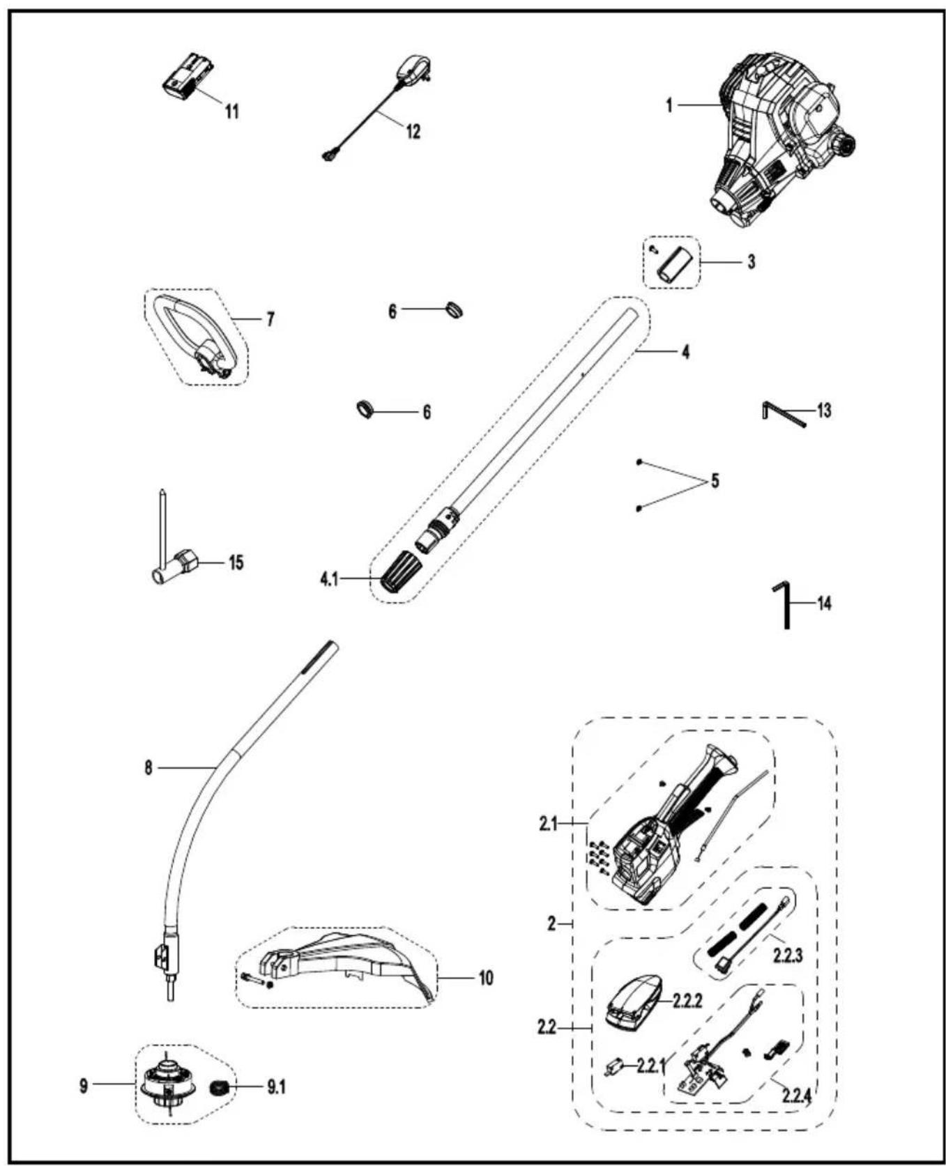
| NPTGCP2517B MANUAL PARTS LIST | |||
| Key Number | Part Number Description Quantity | ||
| 1 | 25cc 2-Cycle Engine Assembly 1 | ||
| 2 | Throttle-body & Starter Set 1 | ||
| 2.1 | Throttle-body Set 1 | ||
| 2.2 | Starter Set 1 | ||
| 2.2.1 | Electric Switch 1 | ||
| 2.2.2 | Starter Switch Assembly | 1 | |
| 2.2.3 | Stop Switch Set 1 | ||
| 2.2.4 | PCB Assembly 1 | ||
| 3 | Connection Cover Assembly | 1 | |
| 4 | Upper Shaft Assembly | 1 | |
| 4.1 | 321007110 Locking Sleeve 1 | ||
| 5 | Cable Clamp 1 | ||
| 6 | Handle Spacer | 2 | |
| 7 | 321007112 Assist Handle 1 | ||
| 8 | Lower Curved Shaft | 1 | |
| 9 | 321007114 | Bump-Feed Spool Assembly | 1 |
| 9.1 | 321007115 Spool Spring 1 | ||
| 10 | 321002105 Debris Guard 1 | ||
| 11 | 321007116 7.2V 1.3Ah Battery 1 | ||
| 12 | 321001127 Charger 1 | ||
| 13 | M5 Hexagon Socket Wrench 1 | ||
| 14 | Hex Key | 1 | |
| 15 | Socket Wrench | 1 | |
Replacement parts highlighted in grey are available for after sales purchase. Replacement of repair or internal parts should only be done by a qualified service professional. Please contact your authorized service dealer or Customer Service at 886-384-8432.
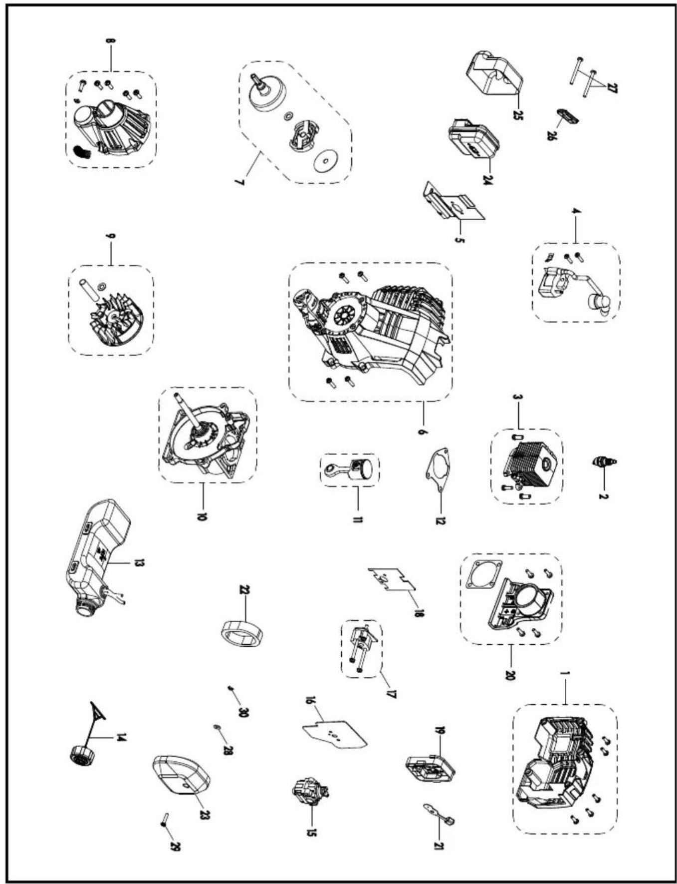
| 25CC 2-CYCLE ENGINE PART LIST | |||
| Key Number | Part Number Description | Quantity | |
| 1 321007 | 84 Rear Engine Cover Assembly 1 | ||
| 2 321001 | 39 Spark Plug 1 | ||
| 3 | Cylinder Assembly 1 | ||
| 4 | Ignition Coil Assembly 1 | ||
| 5 | Insulation Sheet 1 | ||
| 6 | Front Cover Assembly 1 | ||
| 7 | Clutch Assembly 1 | ||
| 8 | Connection Cover Assembly 1 | ||
| 9 | Flywheel Assembly 1 | ||
| 10 | Crankcase Assembly | 1 | |
| 11 | Piston | 1 | |
| 12 | Gasket 1 | ||
| 13 | 321007193 | Fuel Tank | 1 |
| 14 | 321007167 Fuel Cap 1 | ||
| 15 | Carburetor Assembly | 1 | |
| 16 | Washer 1 | ||
| 17 | Carburetor Mount Assembly | 1 | |
| 18 | Washer 1 | ||
| 19 | 321007159 Air Filter Base 1 | ||
| 20 | Crankcase Cover 1 | ||
| 21 | 321007160 Choke Lever 1 | ||
| 22 | 321007161 Air Filter 1 | ||
| 23 | 321007162 Air Filter Cover 1 | ||
| 24 | 321007128 Muffler 1 | ||
| 25 | 321007129 Muffler Cover 1 | ||
| 26 | 321007130 Gasket 1 | ||
| 27 | 321007180 Screw Assembly 2 | ||
| 28 | 321007176 Washer 1 | ||
| 29 | 321007183 Screw 1 | ||
| 30 | 321007173 Spring 1 | ||
Replacement parts highlighted in grey are available for after sales purchase. Replacement of repair or internal parts should only be done by a qualified service professional. Please contact your authorized service dealer or Customer Service at 886-384-8432.
Sección
Página
natural_image
Diagram of a robotic arm with curved arm and base, showing motion direction (no text or symbols)
natural_image
Technical line drawing of a mechanical assembly with a central component and base mount (no text or symbols)Fig. 1 Fig. 2
natural_image
Technical line drawing of a mechanical component with threaded shaft and connector (no text or symbols)natural_image
Technical diagram showing two views of an electrical connector with a cable, labeled Fig. 13 and Fig. 14 (no text or symbols on the diagrams themselves)natural_image
Diagram of a mechanical component with an arrow indicating rotation, labeled 'Fig. 18' (no text or symbols on the diagram itself)

natural_image
Technical line drawing of a mechanical device with motion indicators (no text or symbols)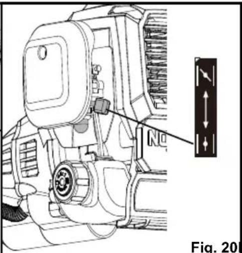
Fig. 20 Fig. 21 Fig.
natural_image
Line drawing of a person using a manual sprinkler to clean grass, labeled as Fig. 25 (no text on diagram)natural_image
Diagram of a mechanical device spraying water onto grass, labeled as Fig. 27 (no text or symbols on the diagram itself)natural_image
Three-step diagram showing mechanical assembly with arrows indicating rotation and assembly steps (no text or symbols)natural_image
Mechanical assembly diagram showing two stages of a spring-loaded component with directional arrows indicating motion (no text or symbols)natural_image
Mechanical component diagram showing a rotating shaft and housing with directional arrows (no text or symbols)Fig. 31 Fig. 32

natural_image
Mechanical assembly diagram showing two stages of a valve mechanism with directional arrows (no text or symbols)natural_image
Technical line drawing of a mechanical gear assembly with no visible text or symbolsnatural_image
Technical diagram showing two views of a mechanical device with internal components and directional arrows, labeled Fig. 40 and Fig. 41 (no text or symbols on the devices themselves)TAPÓN, TANQUE Y LÍNEAS DE GASOLINA

PELIGRO
natural_image
Technical line drawing of a mechanical device with a lever and directional arrow (no text or symbols)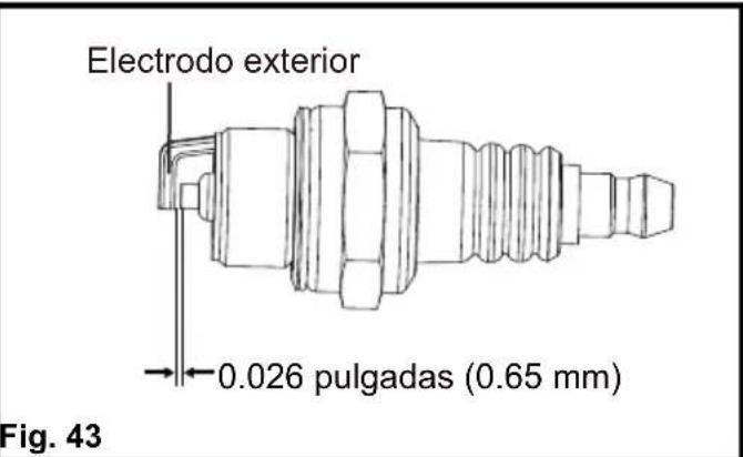

natural_image
Technical line drawing of a mechanical device with a directional arrow indicating motion (no text or symbols)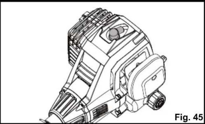
natural_image
Technical line drawing of a mechanical device with no visible text or symbolsALMACENAMIENTO

- NOTICE:
- AVISO:
- PRODUCT SPECIFICATIONS
- WARNING
- READ ALL INSTRUCTIONS AND SAVE THESE INSTRUCTIONS.
- BATTERY PACK
- BATTERY CHARGER
- FCC COMPLIANCE
- SAVE THESE INSTRUCTIONS
- Components
- PACKING LIST
- FITTING THE DEBRIS GUARD (See Figs. 1-3)
- INSTALLING AND REMOVING THE SHAFT (See Figs. 4-6)
- To install the shaft:
- To remove the shaft:
- INSTALLING AND ADJUSTING THE ASSIST HANDLE (See Figs. 7-10)
- INSTALLING AND REMOVING THE BATTERY PACK (See Figs. 11-12)
- To install the battery pack:
- To remove the battery pack:
- BATTERY CHARGING
- CHARGER LEDS
- CHARGING THE BATTERY PACK (See Figs. 13-14)
- BATTERY PACK AND CHARGER
- HANDLING THE FUEL
- DANGER
- FUEL MIXTURE (See Fig. 15)
- Recommended Fuel
- Mixing Tips
- FILLING THE FUEL TANK (See Fig. 16)
- STARTING AND STOPPING THE GRASS TRIMMER (See Figs. 17-23)
- For cold start:
- For warm start:
- BATTERY POWER INDICATOR (See Fig. 24)
- HINT FOR OPTIMUM USE
- TRIMMING (See Fig. 25)
- TRIMMING TIPS (See Figs. 25-26)
- ADVANCING LINE (See Fig. 27)
- CUTTING BLADE (See Fig. 28)
- GENERAL MAINTENANCE
- BATTERY MAINTENANCE
- Storing the battery for 30 days or longer:
- CHARGER MAINTENANCE
- SPOOL REPLACEMENT (See Figs. 29-32)
- LINE REPLACEMENT (See Figs. 33-35)
- TRIMMER HEAD REPLACEMENT (See Fig. 36-37)
- CLEANING THE EXHAUST PORT, MUFFLER AND SPARK ARRESTOR
- IDLE SPEED ADJUSTMENT
- CLEANING THE AIR FILTER (See Figs. 38-41)
- FUEL TANK CAP, TANK AND LINES
- SPARK PLUG REPLACEMENT (See Figs. 42-45)
- STORAGE
- THIS PRODUCT WAS MANUFACTURED WITH A CATALYST MUFFLER
- LawnMaster®
- LawnMaster® No-Pull™ LIMITED WARRANTY
- TAPÓN, TANQUE Y LÍNEAS DE GASOLINA
- PELIGRO
- ALMACENAMIENTO
Brand : LawnMaster
Model : NPTGCP2517B
Category : Lawn mower