
Big Bakers Oven - Heating Nectre - Free user manual and instructions
Find the device manual for free Big Bakers Oven Nectre in PDF.


| Product Type | Wood-Fired Pizza Oven |
| Brand | Nectre |
| Model | Big Bakers Oven |
| Category | Heating |
| Dimensions (approx.) | 600 x 600 x 600 mm |
| Weight (approx.) | 50 kg |
| Cooking Surface | Firebrick floor |
| Fuel | Wood logs |
| Maximum Temperature | 500°C |
| Primary Functions | Pizza, bread, roasting, baking |
| Door Material | Cast iron with glass window |
| Chimney Connection | Standard flue (150 mm) |
| Installation | Outdoor or sheltered area |
| Maintenance | Ash removal, door seal check |
| Cleaning | Wire brush for grate, damp cloth for exterior |
| Safety Features | Cool-touch handle, heat-resistant base |
| Repairability | Replaceable firebricks, door seals, grate |
| Warranty | 1 year |
| Manual Languages | English, French, Spanish (downloadable PDF) |
Frequently Asked Questions - Big Bakers Oven Nectre
User questions about Big Bakers Oven Nectre
0 question about this device. Answer the ones you know or ask your own.
Ask a new question about this device
Download the instructions for your Heating in PDF format for free! Find your manual Big Bakers Oven - Nectre and take your electronic device back in hand. On this page are published all the documents necessary for the use of your device. Big Bakers Oven by Nectre.
USER MANUAL Big Bakers Oven Nectre
Nectre Big Bakers Oven
Installation Instructions

natural_image
3D rendering of a NECTRE industrial stove with two doors and control panel (no text or symbols visible)Keep these instructions for future reference

Australian
Home Heating
Association Inc.

Glen Dimplex Australia proudly supports the activities of Landcare Australia through its membership of the AHHA
CONTENTS
1. INSTALLATION .... 1
1.1. IMPORTANT INFORMATION .... 1
1.2. INSTALLING THE HEATER....2
1.2.1. Positioning the Heater 2
1.2.2. Standard Installation....2
1.2.3. Corner Installation 2
1.2.4. Floor Protector 2
1.3. REDUCING CLEARANCES TO COMBUSTIBLES .....3
1.4. INSTALLING THE BYPASS DAMPER HANDLE ....3
1.5. INSTALLING THE FLUE....4
1.6. INSTALLING FIRE BRICKS....4
1.7. INSTALLING FIREBOX SIDE SHIELDS 4
1.8. INSTALLING BAFFLE PLATE 5
1.9. INSTALLING TOP AIR CONTROL HANDLE ....5
1.10. TECHNICAL DRAWINGS ....5
1. INSTALLATION
THE INSTALLATION INSTRUCTIONS IN THIS MANUAL APPLY TO THE NECTRE BIG BAKERS OVEN.
1.1. IMPORTANT INFORMATION
The unit must be installed according to all manufacturers' instructions included in this manual. The manufacturer is not liable for installations that do not meet the requirements outlined in this manual.
Most building regulatory authorities in Australia require any wood heater installation to comply with Installation Standard AS/NZS 2918. Different states and councils may have varying regulations. Check local building regulations before installing the appliance.
All Nectre wood heaters have been tested to ensure they will meet the appropriate safety standard requirements if the instructions in this manual are followed. As the safety and emissions performance can be affected by altering the appliance, no modifications are allowed without written permission from the manufacturer.
WE RECOMMEND THAT THE INSTALLATION OF YOUR NECTRE WOOD HEATER BE CARRIED OUT BY A QUALIFIED INSTALLER.
WARNING: THE APPLIANCE AND FLUE SYSTEM SHALL BE INSTALLED IN ACCORDANCE WITH AS/NZS 2918 AND THE APPROPRIATE REQUIREMENTS OF THE RELEVANT BUILDING CODE OR CODES.
ANY MODIFICATION OF THE APPLIANCE THAT HAS NOT BEEN APPROVED IN WRITING BY THE TESTING AUTHORITY IS CONSIDERED TO BE IN BREACH OF THE APPROVAL GRANTED FOR COMPLIANCE WITH AS/NZS 4012 & AS/NZS 4013.
CAUTION: MIXING OF APPLIANCE OR FLUE-SYSTEM COMPONENTS FROM DIFFERENT SOURCES OR MODIFYING THE DIMENSIONAL SPECIFICATION OF COMPONENTS MAY RESULT IN HAZARDOUS CONDITIONS. WHERE SUCH ACTION IS CONSIDERED, THE MANUFACTURER SHOULD BE CONSULTED IN THE FIRST INSTANCE.
CAUTION: CRACKED AND BROKEN COMPONENTS, EG. GLASS PANELS OR CERAMIC TILES, MAY RENDER THE INSTALLATION UNSAFE.
1.2. INSTALLING THE HEATER
1.2.1. Positioning the Heater
Review the necessary clearances specified in this section before considering where to position the heater.
Also check the practicability of installing the flue system in relation to any obstructing roof beams before positioning the heater.
The clearance distances can only be reduced if the surrounding walls are made of non-combustible material such as stone, brick or concrete. If non-combustible material, distance can be reduced to 100 mm. Alternatively, shielding of the wall(s) can reduce clearances (refer to next section for more detail).
1.2.2. Standard Installation
Dimensions given in the image below represent the minimum clearance (in millimetres) to combustible materials.
Side clearance = 325mm
Rear clearance = 125mm

1.2.3. Corner Installation
Dimensions given in the image below represent the minimum clearance (in millimetres) to combustible materials.
Corner clearance = 275mm

1.2.4. Floor Protector
Unless the heater will be standing on a heat resistant floor such as concrete slab with slate or tiles, it will be necessary to provide a floor protector.
The minimum required dimensions for the floor protector are shown in the previous images. It must extend no less than 300mm in front of the door opening, no less than 200mm either side of the door opening and extend under the heater. Minimum dimensions for the floor protector are 900mm wide by 900mm deep. It may be desirable, for example aesthetic reasons, for the floor protector to be larger than these minimum dimensions.
The floor protector shall be constructed of non-combustible material no less than 15mm thick and with a thermal conductivity not greater than 0.33W/m °K, eg. compressed cement sheet.
The floor protector may be laid directly on the combustible floor.
For more details and variations on floor protectors refer to AS/NZS 2918 Clause 2.2, 3.3.1, & 3.3.2.
1.3. REDUCING CLEARANCES TO COMBUSTIBLES
If it is necessary to install a heater closer to a combustible surface than the stated requirements in this installation manual, it must be done in accordance with Australian Standard AS/NZS 2918:2018 Section 3, Tables 3.1 & 3.2.
Shield Construction: The shield shall be constructed from a heat resistant material. The shield must be fixed to the surface that requires protection and NOT the heater.
The Standard allows three options to reduce stated clearances.
Single layer of continuous material with Minimum Air Gap of 12mm—Clearance Factor = 0.40
Single layer of continuous material with Minimum Air Gap of 25mm—Clearance Factor = 0.30
Two spaced layers of continuous material with Minimum Air Gaps of 12mm + 12mm—Clearance Factor = 0.20
The shielding must be open at the top and bottom (vented) to allow a continuous air flow. It is this air flow that keeps the surface requiring protection cool. Fixings should not impede this air flow.
The shielding needs to go far enough along and up the wall so that the original side and rear required clearances are not compromised. As the flue is now closer to the wall the shielding should also protect the wall from the flue pipe.
Example:
The side wall clearance for a heater is 325mm.
A 12mm gapped shield on the wall with a factor of 0.40.
Calculate: 325mm x 0.40 = 130mm. This is the new side wall minimum clearance.
The shielding needs to be large enough so that none of the original clearances of 325mm are compromised.
1.4. INSTALLING THE BYPASS DAMPER HANDLE
Before installing the flue, the bypass damper handle must be fitted. The handle is supplied inside the firebox.
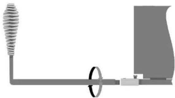
1) Insert the threaded end of the handle into the 10mm hole on left side of heater.
2) Looking down through the flue spigot, locate the threaded end of the handle with the connector attached to the by-pass damper.
3) Screw the handle all the way into the nut until tight.
natural_image
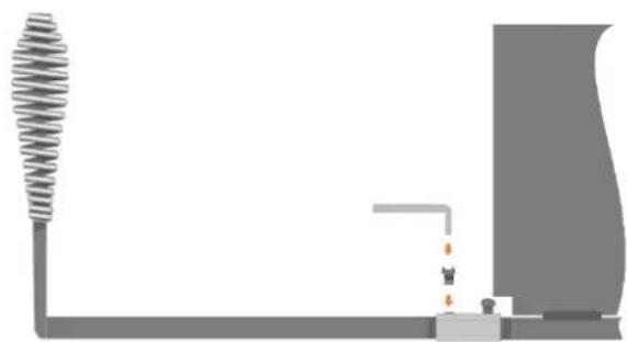
Pure mechanical diagram showing a spring-loaded pipe connected to a cylindrical component (no text or symbols)4) Lock into place with the M4 screw.
natural_image
Pure diagram of a mechanical or fluid system with spring, pipe, and valve components (no text or symbols)The position of the handle should be at approximately 11 o'clock when the damper is open, and 1 o'clock when the damper is shut.
1.5. INSTALLING THE FLUE
Before installing flue, the bypass damper handle must be fitted (see section 'Installing the Bypass Damper Handle').
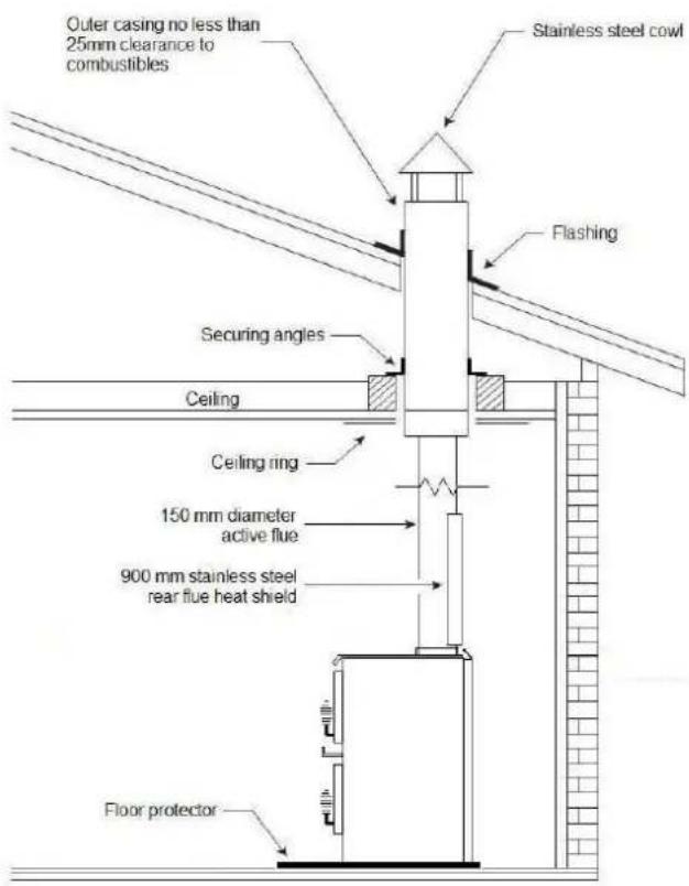
The flue system used when installing the heater MUST comply with the current installation standard AS/NZS 2918.
Full instructions on the installation of the flue will be supplied with the flue kit. These MUST be adhered to, including the minimum exit height from the top of the floor protector being not less than 4.6m, and the minimum exit height above the roof line of roof ridge as detailed in the instructions.
The flue must be fitted with a 900mm long, minimum 150° arc, stainless steel unpainted rear flue shield.
If the draft is insufficient or periodic down drafting occurs and the heater smokes or only burns slowly, extending the flue or fitting a specialist cowl will usually resolve the issue.
1.6. INSTALLING FIRE BRICKS
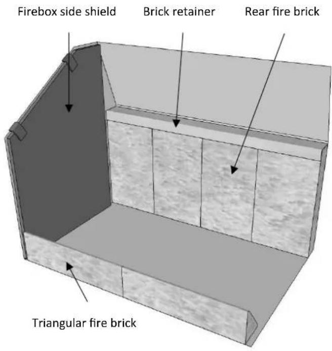
The Nectre Big Bakers Oven comes with 4 bricks (230 x 115 x 38mm) held by a 495mm long brick retainer and 2 triangular bricks (50 x 70 x 250mm) for the front.
1) Place the four fire bricks upright, up against the rear wall of the firebox.
2) Place the brick retainer over the top of the bricks to hold them in place.
3) Place the triangular firebricks at the front of the firebox beneath the door opening.
The firebricks may already be in place upon arrival of the new appliance.
The Nectre Big Bakers Oven is supplied with two 8mm thick sacrificial shields fitted to the sides of the firebox to protect the walls of the firebox.
Lugs on the shields allow them to hang over the angled cut-out on the sides of the firebox along the top.
The firebox side shields may already be in place upon arrival of the new appliance.
1.8. INSTALLING BAFFLE PLATE
The Nectre Big Bakers Oven is supplied with a 248 x 463 x 6mm baffle plate. This rests on the two lugs welded to the inside front of the firebox and on the brick retainer at the back of the heater.
Ensure the baffle plate is pushed all the way to the back so it does not fall during operation.
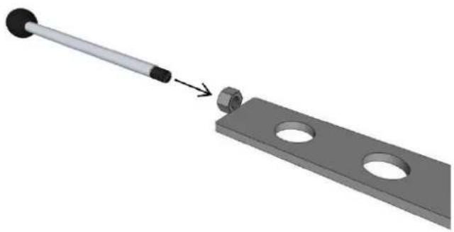
1.9. INSTALLING TOP AIR CONTROL HANDLE
A stainless steel rod with a thread at one end and black knob on the other will have been supplied in the heater.
1) Pass the threaded end of the rod through the hole near the top front corner on the left side of the heater.
2) Push the rod through until it has located the nut on the air slide
3) Screw rod until tight.
4) Check that the rod slides freely back and forth.
natural_image
3D diagram of a mechanical assembly with a rod and nut, showing a bolt inserted into a plate (no text or symbols)Glen Dimplex AUSTRALIA
Glen Dimplex Australia Pty Ltd
1340 Ferntree Gully Road,
Scoresby Victoria 3179
Australia
T: 1300 556 816 | F: 1800 058 900
Email: sales@glendimplex.com.au
- Nectre Big Bakers Oven
- Installation Instructions
- CONTENTS
- INSTALLATION .... 1
- INSTALLATION
- IMPORTANT INFORMATION
- INSTALLING THE HEATER
- Positioning the Heater
- Standard Installation
- Corner Installation
- Floor Protector
- REDUCING CLEARANCES TO COMBUSTIBLES
- INSTALLING THE BYPASS DAMPER HANDLE
- INSTALLING THE FLUE
- INSTALLING FIRE BRICKS
- INSTALLING BAFFLE PLATE
- INSTALLING TOP AIR CONTROL HANDLE
- Glen Dimplex AUSTRALIA
Brand : Nectre
Model : Big Bakers Oven
Category : Heating