SuperChassis SC811 - PC Case Supermicro - Free user manual and instructions
Find the device manual for free SuperChassis SC811 Supermicro in PDF.


| Product Type | 1U Rackmount PC Case (Server Chassis) |
| Brand | Supermicro |
| Model | SuperChassis SC811 |
| Form Factor | 1U (1.75" height) |
| Supported Drive Bays | 2x SAS/SATA or 2x SCSI (depending on model) |
| Power Supply Options | From 260W to 600W (Gold, Platinum, or DC); auto-switching 100-240V |
| Expansion Slots | 1 full-length/full-height PCIe slot via riser card |
| Cooling | 2 heavy-duty blowers (hot-swap capable) |
| Front Panel | Power button, Reset button, 5 LEDs (Info, NIC1, NIC2, HDD, Power) |
| Backplane | SAS-810TQ (SAS/SATA) or SATA-810; compatible with SGPIO/I2C |
| Rack Mounting | Supports racks 29" to 35.25" deep; includes inner/outer rails and brackets |
| Motherboard Compatibility | Standard 1U server motherboard (ATX or proprietary form factor) |
| Dimensions (approx.) | 1.7" H x 17.2" W x 25.6" D (typical for 1U chassis) |
| Weight (approx.) | 15-20 lbs depending on configuration |
| Operating Temperature | 0°C to 35°C (ambient), up to 45°C with warnings |
| Safety Certifications | UL, CSA, CE; complies with California Perchlorate and lead solder warnings |
| Included Accessories | Power cord, hard drive carriers, screws, air shroud, mylar sheet, rails |
| Maintenance | Tool-less cover removal; hot-swap fans; replaceable power supply and DVD-ROM |
| Warranty | Standard Supermicro warranty (contact distributor for details) |
Frequently Asked Questions - SuperChassis SC811 Supermicro
User questions about SuperChassis SC811 Supermicro
0 question about this device. Answer the ones you know or ask your own.
Ask a new question about this device
Download the instructions for your PC Case in PDF format for free! Find your manual SuperChassis SC811 - Supermicro and take your electronic device back in hand. On this page are published all the documents necessary for the use of your device. SuperChassis SC811 by Supermicro.
USER MANUAL SuperChassis SC811 Supermicro
natural_image
Front view diagram of a rack-mounted server unit with multiple ports and indicator lights (no text or labels)SC811TQ-600B SC811TQ-350B
The information in this User's Manual has been carefully reviewed and is believed to be accurate. The vendor assumes no responsibility for any inaccuracies that may be contained in this document, makes no commitment to update or to keep current the information in this manual, or to notify any person or organization of the updates. Please Note: For the most up-to-date version of this manual, please see our web site at www.supermicro.com.
Super Micro Computer, Inc. ("Supermicro") reserves the right to make changes to the product described in this manual at any time and without notice. This product, including software and documentation, is the property of Supermicro and/or its licensors, and is supplied only under a license. Any use or reproduction of this product is not allowed, except as expressly permitted by the terms of said license.
IN NO EVENT WILL SUPERMICRO BE LIABLE FOR DIRECT, INDIRECT, SPECIAL, INCIDENTAL, SPECULATIVE OR CONSEQUENTIAL DAMAGES ARISING FROM THE USE OR INABILITY TO USE THIS PRODUCT OR DOCUMENTATION, EVEN IF ADVISED OF THE POSSIBILITY OF SUCH DAMAGES. IN PARTICULAR, SUPERMICRO SHALL NOT HAVE LIABILITY FOR ANY HARDWARE, SOFTWARE, OR DATA STORED OR USED WITH THE PRODUCT, INCLUDING THE COSTS OF REPAIRING, REPLACING, INTEGRATING, INSTALLING OR RECOVERING SUCH HARDWARE, SOFTWARE, OR DATA.
Any disputes arising between manufacturer and customer shall be governed by the laws of Santa Clara County in the State of California, USA. The State of California, County of Santa Clara shall be the exclusive venue for the resolution of any such disputes. Super Micro's total liability for all claims will not exceed the price paid for the hardware product.
California Best Management Practices Regulations for Perchlorate Materials: This Perchlorate warning applies only to products containing CR (Manganese Dioxide) Lithium coin cells. “Perchlorate Material-special handling may apply. See www.dtsc.ca.gov/hazardouswaste/perchlorate”
WARNING: Handling of lead solder materials used in this product may expose you to lead, a chemical known to the State of California to cause birth defects and other reproductive harm.
Manual Revision 2.0a
Release Date: August 26, 2013
Unless you request and receive written permission from Super Micro Computer, Inc., you may not copy any part of this document.
Information in this document is subject to change without notice. Other products and companies referred to herein are trademarks or registered trademarks of their respective companies or mark holders.
Copyright © 2013 by Super Micro Computer, Inc.
All rights reserved.
Printed in the United States of America
Preface
About This Manual
This manual is written for professional system integrators and PC technicians. It provides information for the installation and use of the SC811 1U chassis. Installation and maintenance should be performed by experienced technicians only.
This document lists compatible parts available when this document was published. Always refer to the our Web site for updates on supported parts and configurations.
Manual Organization
Chapter 1 Introduction
The first chapter describes the main features of the SC811 chassis. This chapter also includes contact information.
Chapter 2 Warning Statements for AC Systems
This chapter discusses warnings, precautions, and system safety. It is recommended that you thoroughly familiarize yourself with the safety precautions in this chapter before installing and servicing the chassis.
Chapter 3 System Interface
Refer to this chapter for details on the system interface, which includes the functions and information provided by the control panel on the chassis as well as other LEDs located throughout the system.
Chapter 4 Chassis Setup and Maintenance
Follow the procedures given in this chapter when installing and removing components, or reconfiguring your chassis.
Chapter 5 Rack Installation
Refer to this chapter for instructions to install the chassis into a rack. Follow the procedures given in this chapter when installing, removing or reconfiguring your chassis in a rack environment.
Appendix A Chassis Cables
Appendix B Power Supply Specifications
Appendix C SAS-810TQ Backplane Specifications
Appendix D SATA-810 Backplane Specifications
Note: For information on the CSE-SCA-004 SCSI backplane contact Supermicro's Technical Support department at www.supermicro.com.
Contents
Chapter 1 Introduction
1-1 Overview 1-1
1-2 Shipping List.... 1-1
1-3 Contacting Supermicro.... 1-3
1-4 Unpacking the System 1-4
1-5 Returning Merchandise for Service.... 1-4
1-6 Where to get Replacement Components.... 1-4
Chapter 2 Standardized Warning Statements for AC Systems
2-1 About Standardized Warning Statements.... 2-1
Warning Definition 2-1
Installation Instructions....2-4
Circuit Breaker 2-5
Power Disconnection Warning 2-6
Equipment Installation....2-8
Restricted Area....2-9
Battery Handling....2-10
Redundant Power Supplies 2-12
Backplane Voltage 2-13
Comply with Local and National Electrical Codes 2-14
Product Disposal 2-15
Hot Swap Fan Warning....2-16
Power Cable and AC Adapter 2-18
Chapter 3 System Interface
3-1 Overview 3-1
3-2 Control Panel Buttons 3-2
3-3 Control Panel LEDs 3-2
3-4 Drive Carrier LEDs....3-4
SAS/SATA Drives 3-4
SCSI Drives 3-4
Chapter 4 Chassis Setup and Maintenance
4-1 Overview 4-1
4-2 Removing Power from the System 4-1
4-3 Removing the Chassis Cover 4-2
4-4 Removing and Installing Hard Drives 4-3
4-5 Installing the Motherboard 4-5
4-6 Installing the Expansion Card....4-7
4-7 Installing the Air Shroud.... 4-8
Installation Complete....4-8
General Maintenance....4-8
4-8 System Blowers 4-9
4-9 Power Supply 4-10
4-10 Other Chassis Components 4-12
Changing the DVD-ROM....4-12
Changing the Control Panel....4-12
Chapter 5 Rack Installation
5-1 Preparing for Setup.... 5-1
Choosing a Setup Location....5-1
Ambient Operating Temperature 5-1
Adequate Airflow 5-1
Circuit Overloading....5-2
Reliable Ground 5-2
Physical Rack Precautions 5-2
General Server Precautions....5-2
5-2 Rack Mounting Instructions.... 5-3
Identifying the Sections of the Rails 5-3
Rail Brackets 5-3
Installing the Chassis into a Rack....5-7
Appendix A Cables, Screws, and Other Accessories
A-1 Overview ......A-1
A-2 Cables Included with SC811TQ Chassis (SAS/SATA) ......A-1
A-3 Cables Included with SC811S Chassis (SCSI)....A-1
A-4 Cables Included with the SC811T Chassis (SCSI)....A-2
A-5 Compatible Cables....A-2
Alternate SAS/SATA Cables....A-2
Extending Power Cables....A-3
Front Panel to the Motherboard....A-3
A-6 Chassis Screws....A-4
Appendix B SC811 Power Supply Specifications
Appendix C SAS-810TQ Safety Guidelines
C-1 ESD Safety Guidelines ......C-1
C-2 General Safety Guidelines....C-1
C-3 An Important Note to Users....C-2
C-4 Introduction to the SAS-810TQ Backplane....C-2
Connectors and Jumpers
C-5 Front Connectors ...... C-3
Front Components ......C-3
C-6 Front Connectors and Pin Definitions....C-4
C-7 Front Jumper Locations and Pin Definitions....C-6
Explanation of Jumpers ......C-6
I²C and SGPIO Modes and Jumper Settings ......C-7
Front LED Indicators....C-8
C-8 Rear Connectors and LED Indicators....C-9
Appendix D SATA-810 Backplane Specifications
D-1 ESD Safety Guidelines ....D-1
D-2 General Safety Guidelines....D-1
D-3 An Important Note to Users....D-2
D-4 Introduction to the SATA-810 Backplane....D-2
D-5 Front Connectors ....D-3
Front Connectors ....D-3
D-6 Front Connector Definitions ....D-4
D-7 Front Jumper Locations and Pin Definitions....D-5
Explanation of Jumpers ....D-5
Front LED Indicator.....D-6
D-8 Rear Connectors and LED Indicators....D-7
Rear Connectors....D-7
Rear LEDs.....D-8
Notes
Chapter 1
Introduction
1-1 Overview
Supermicro's SC811 1U chassis features a unique and highly-optimized design. The chassis is equipped with high efficiency power supply in a 1U form factor.
Note: A complete list of safety warnings is provided on the Supermicro web site at http://www.supermicro.com/about/policies/safety_information.cfm.
1-2 Shipping List
Part Numbers
Please visit the following link for the latest shipping lists and part numbers for your particular chassis model www.supermicro.com.
| SC811 Chassis Specs | |||
| Mode HDD I/O | Slots Power | Supply | |
| SC811TQ-600B 2x SAS/SATA 1x FF | 600W(Gold Level) | ||
| SC811L-600B 2x Fixed | 1x FF | 600W(Gold Level) | |
| SC811TQ-520/SC811TQ-520B | 2x SAS/SATA 1x FF | 520W | |
| SC811S-520/SC822S-520B* | 2 U320 SCSI 1x FF | 520W | |
| SC811i-520/SC811i-520B | 2x Fixed 1x FF | 520W | |
| SC811TQ-441B 2x SAS/SATA 1x FF | 440W(Platinum Level) | ||
| SC811S-420/SC811S-420B* | 2x U320 SCSI 1x FF | 420W | |
| SC811T-420/SC811T-420B* | 2x SATA 1x FF | 420W | |
| SC811i-420 / SC811i-420B* | 2x Fixed 1x FF 420W | ||
| SC811S-410 / SC811S-410B* | 2x U320 SCSI 1x FF 410W DC | ||
| SC811T-410 / SC811T-410B | 2x SATA 1x FF 410W DC | ||
| SC811i-410 / SC811i-410B | 2x Fixed 1x FF 410W DC | ||
| SC811TQ-350B 2x SAS/SATA 1x FF | 350W (Gold Level) | ||
| SC811L-350B 2x Fixed 1x FF | 350W (Gold Level) | ||
| SC811S-300 / SC811S-300B* | 2x U320 SCSI 1x FF 300W | ||
| SC811T-300 / SC811T-300B | 2x SATA 1x FF 300W | ||
| SC811i-300 / SC811i-300B | 2x Fixed 1x FF 300W | ||
| SC811TQ-280 / SC811TQ-280B | 2x SAS 1x FF 280W | ||
| SC811S-280 / SC811S-280B* | 2x U320 SCSI 1x FF 280W | ||
| SC811i-280 / SC811i-280B | 2x Fixed 1x FF 280W | ||
| SC811TQ-260 / SC811TQ-260B | 2x SAS/SATA 1x FF 260W | ||
| SC811S-260 / SC811S-260B* | 2x U320 SCSI 1x FF 260W | ||
| SC811T-260 / SC811T-260B | 2x SATA 1x FF 260W | ||
| SC811i-260 / SC811i-260B | 2x Fixed 1x FF 260W | ||
* End of Life
1-3 Contacting Supermicro
Headquarters
Address: Super Micro Computer, Inc.
980 Rock Ave.
San Jose, CA 95131 U.S.A.
Tel: +1 (408) 503-8000
Fax: +1 (408) 503-8008
Email: marketing@supermicro.com (General Information)
support@supermicro.com (Technical Support)
Web
www.supermicro.com
Site:
Headquarters
Address: Super Micro Computer, Inc.
980 Rock Ave.
San Jose, CA 95131 U.S.A.
Tel: +1 (408) 503-8000
Fax: +1 (408) 503-8008
Email: marketing@supermicro.com (General Information)
support@supermicro.com (Technical Support)
Web
www.supermicro.com
Site:
Asia-Pacific
Address: Super Micro Computer, Inc.
3F, No. 150, Jian 1st Rd.
Zhonghe Dist., New Taipei City 23511
Taiwan (R.O.C)
Tel: +886-(2) 8226-3990
Fax: +886-(2) 8226-3992
Web
1-4 Unpacking the System
Inspect the box in which the chassis was shipped. If the chassis itself shows damage, file a damage claim with the carrier.
1-5 Returning Merchandise for Service
A receipt or copy of your invoice marked with the date of purchase is required before any warranty service will be rendered. You can obtain service by calling your vendor for a Returned Merchandise Authorization (RMA) number. When returning to the manufacturer, the RMA number should be prominently displayed on the outside of the shipping carton, and mailed prepaid or hand-carried. Shipping and handling charges will be applied for all orders that must be mailed when service is complete.
For faster service, RMA authorizations may be requested online (http://www.supermicro.com/support/rma/).
Whenever possible, repack the chassis in the original Supermicro carton, using the original packaging material. If these are no longer available, be sure to pack the chassis securely, using packaging material to surround the chassis so that it does not shift within the carton and become damaged during shipping.
This warranty only covers normal consumer use and does not cover damages incurred in shipping or from failure due to the alteration, misuse, abuse or improper maintenance of products.
During the warranty period, contact your distributor first for any product problems.
1-6 Where to get Replacement Components
Although not frequently, you may need replacement parts for your system. To ensure the highest level of professional service and technical support, we strongly recommend purchasing exclusively from our Supermicro Authorized Distributors/System Integrators/Resellers. A list of Supermicro Authorized Distributors/System Integrators/Reseller can be found at: http://www.supermicro.com. Click the Where to Buy link.
Chapter 2
Standardized Warning Statements for AC Systems
2-1 About Standardized Warning Statements
The following statements are industry standard warnings, provided to warn the user of situations which have the potential for bodily injury. Should you have questions or experience difficulty, contact Supermicro's Technical Support department for assistance. Only certified technicians should attempt to install or configure components.
Read this appendix in its entirety before installing or configuring components in the Supermicro chassis.
These warnings may also be found on our web site at http://www.supermicro.com/about/policies/safety_information.cfm.
Warning Definition

Warning!
This warning symbol means danger. You are in a situation that could cause bodily injury. Before you work on any equipment, be aware of the hazards involved with electrical circuitry and be familiar with standard practices for preventing accidents.
警告の定義
この警告サインは危険を意味します。
Installation Instructions

Warning!
Read the installation instructions before connecting the system to the power source. 設置手順書
This product relies on the building's installation for short-circuit (overcurrent) protection. Ensure that the protective device is rated not greater than: 250 V, 20 A.
サーキット・ブレーカー
Power Disconnection Warning

Warning!
The system must be disconnected from all sources of power and the power cord removed from the power supply module(s) before accessing the chassis interior to install or remove system components.
電源切断の警告
Equipment Installation

Warning!
Only trained and qualified personnel should be allowed to install, replace, or service this equipment.
機器の設置
This unit is intended for installation in restricted access areas. A restricted access area can be accessed only through the use of a special tool, lock and key, or other means of security. (This warning does not apply to workstations).
アクセス制限区域
There is the danger of explosion if the battery is replaced incorrectly. Replace the battery only with the same or equivalent type recommended by the manufacturer. Dispose of used batteries according to the manufacturer's instructions
電池の取り扱い
Redundant Power Supplies

Warning!
This unit might have more than one power supply connection. All connections must be removed to de-energize the unit.
冗長電源装置
Hazardous voltage or energy is present on the backplane when the system is operating. Use caution when servicing.
バックプレーンの電圧
Comply with Local and National Electrical Codes

Warning!
Installation of the equipment must comply with local and national electrical codes.
地方および国の電気規格に準拠
Ultimate disposal of this product should be handled according to all national laws and regulations.
製品の廃棄
The fans might still be turning when you remove the fan assembly from the chassis.
Keep fingers, screwdrivers, and other objects away from the openings in the fan assembly's housing.
ファン・ホットスワップの警告
Power Cable and AC Adapter

Warning!
When installing the product, use the provided or designated connection cables, power cables and AC adaptors. Using any other cables and adaptors could cause a malfunction or a fire. Electrical Appliance and Material Safety Law prohibits the use of UL or CSA-certified cables (that have UL/CSA shown on the code) for any other electrical devices than products designated by Supermicro only.
電源コードとACアダプター
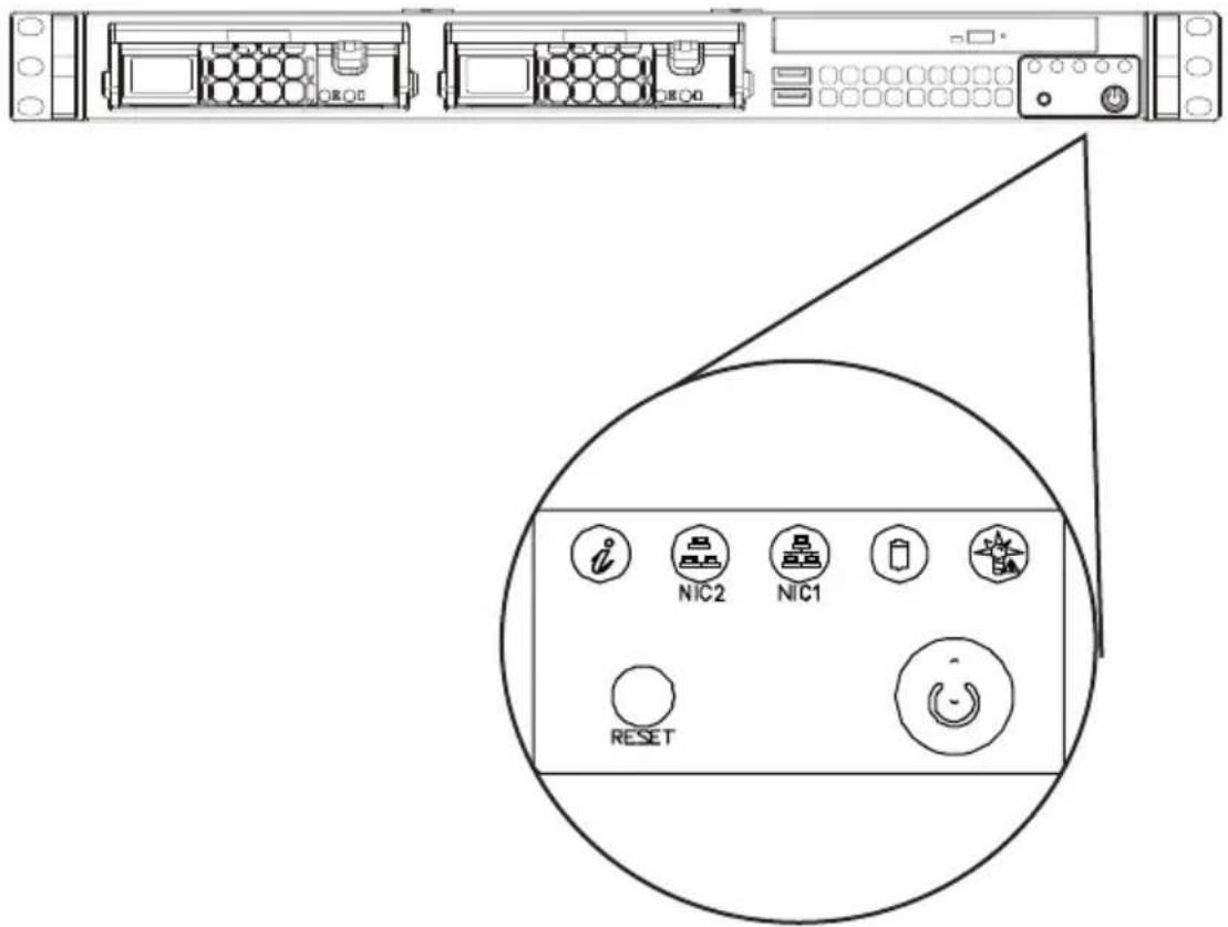
There are several LEDs on the control panel and on the drive carriers to keep you informed of the status of the system. Most SC811 models include two buttons on the chassis control panel: a reset button and an on/off switch. This chapter explains the meanings of the LED indicators and the appropriate responses.
3-2 Control Panel Buttons
There are two push-buttons located on the front of the chassis. These are (from left to right) a reset button and a power on/off button.

- Reset: The reset button is used to reboot the system.
- Power: The main power switch is used to apply or remove power from the power supply to the server system. Turning off system power with this button removes the main power but keeps standby power supplied to the system. Therefore, you must unplug system before servicing.
3-3 Control Panel LEDs
The control panel located on the front of the SC811 chassis has five LEDs. They provide you with critical information related to different parts of the system. This section explains what each LED indicates when illuminated and any corrective action.

• Information LED: Alerts operator of several states, as noted in the table below.
| Informational LED | |
| Status Description | |
| Continuously on and red | An overheat condition has occurred. (This may be caused by cable congestion.) |
| Blinking red (1Hz) Fan failure | check for an inoperative fan. |
| Blinking red (0.25Hz) Power | failure, check for a non-operational power supply. |
| Solid blue | Local UID has been activated. Use this function to locate the server in a rack mount environment. |
| Blinking blue | Remote UID is on. Use this function to identify the server from a remote location. |
- NIC2: Indicates network activity on GLAN2 when flashing.
• NIC1: Indicates network activity on GLAN1 when flashing.
- HDD: Indicates IDE channel activity. SAS/SATA drive, SCSI drive, and/or DVD-ROM drive activity when flashing.

- Power: Indicates power is being supplied to the system's power supply units. This LED should normally be illuminated when the system is operating.
3-4 Drive Carrier LEDs
The SC811 chassis uses SAS/SATA or SCSI drives, but not both.
SAS/SATA Drives
Each SAS/SATA drive carrier has two LEDs.
- Green: Each Serial ATA drive carrier has a green LED. When illuminated, this green LED (on the front of the SATA drive carrier) indicates drive activity. A connection to the SATA backplane enables this LED to blink on and off when that particular drive is being accessed.
- Red: The red LED to indicate an SAS/SATA drive failure. If one of the SAS/SATA drives fail, you should be notified by your system management software.
SCSI Drives
Each SCSI drive carrier has two LEDs.
- Green: When illuminated, the green LED on the front of the SCSI drive carrier indicates drive activity. A connection to the SCSI backplane enables this LED to blink on and off when that particular drive is being accessed.
- Red: The SAF-TE compliant backplane activates the red LED to indicate a drive failure. If one of the SCSI drives fail, you should be notified by your system management software.
Chapter 4
Chassis Setup and Maintenance
4-1 Overview
This chapter covers the steps required to install components and perform maintenance on the chassis. The only tool required is a Phillips screwdriver.
Review the warnings and precautions listed in the manual before setting up or servicing this chassis. These include information in Chapter 2: System Safety and the warning/precautions listed in the setup instructions
4-2 Removing the Power from the System
Before performing any setup or maintenance on the chassis, use the following procedure to ensure that power has been removed from the system.
- Use the operating system to power down the node, following the on-screen prompts.
- After the system has completely shut-down, carefully grasp the head of the power cord and gently pull it out of the back of the power supply. If your system has dual power supplies, remove the cords from both power supplies.
- Disconnect the cord from the power strip or wall outlet.
4-3 Removing the Chassis Cover
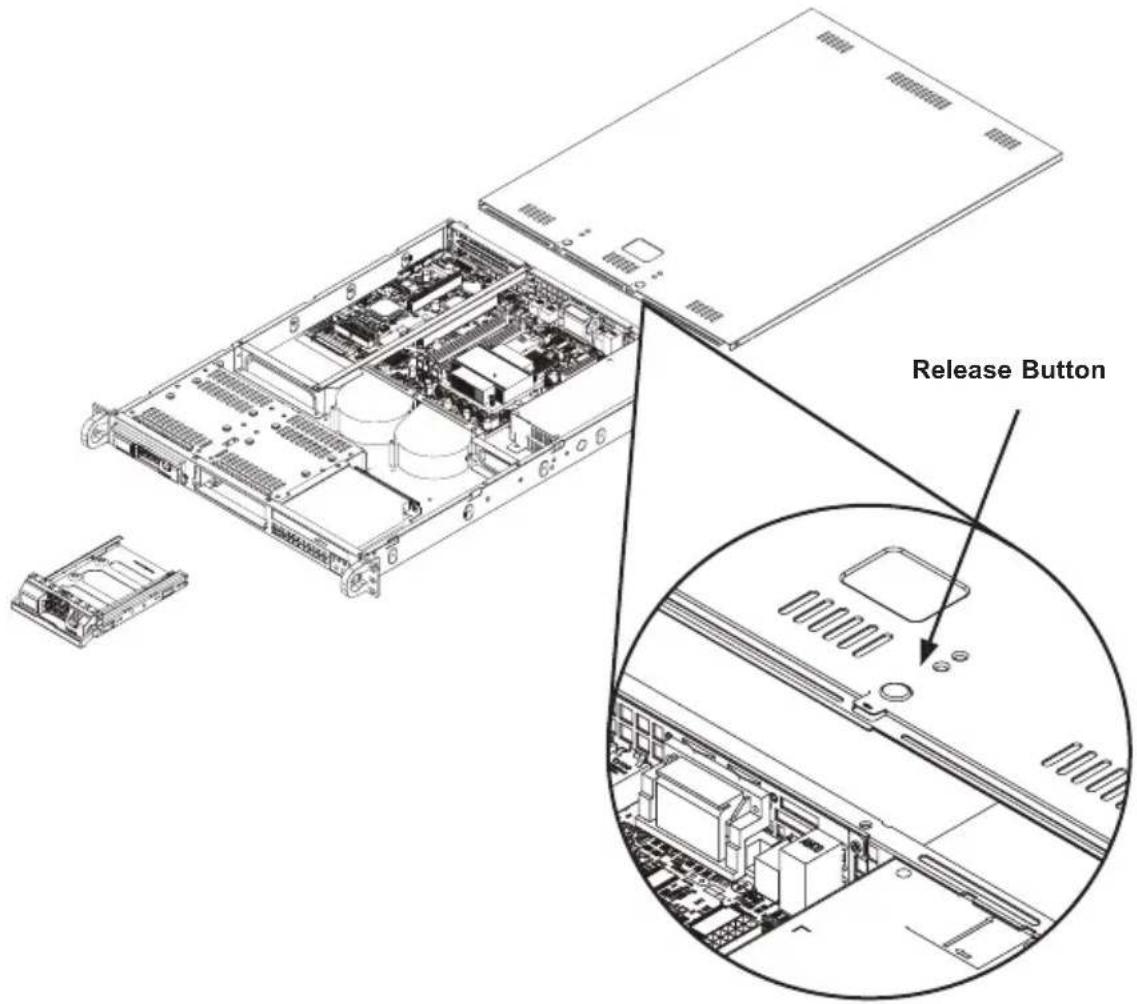
Figure 4-1. Removing the Chassis Cover
Removing the Chassis Cover
- Press the release buttons to remove the cover from the locked position. Press both buttons at the same time.
- Once the top cover is released from the locked position, slide the cover toward the rear of the chassis. The cover will only slide about two inches.
- Lift the cover off the chassis.
Caution: Except for short periods of time, do not operate the server without the cover in place. The chassis cover must be in place to allow proper airflow and prevent overheating.
4-4 Removing and Installing Hard Drives
natural_image
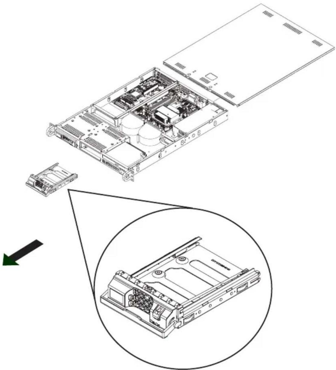
Technical diagram of a server rack with internal components and an inset view showing internal structure (no text or labels)Figure 4-2. Removing a Hard Drive
Removing Hard Drive Trays from the Chassis
- Press the release button on the drive carrier. This extends the drive carrier handle.
- Use the handle to pull the drive out of the chassis.
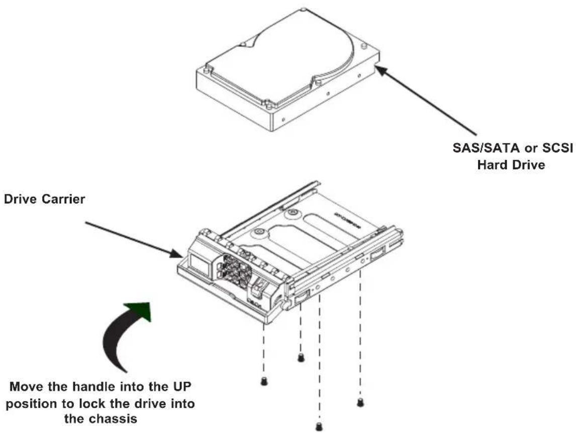
Figure 4-3. Removing the Drive from the Tray
Installing a Hard Drive
- Remove the hard drive tray from the chassis.
- Mount a hard drive into the drive carrier using four screws as illustrated.
- Replace the hard drive carrier in the chassis with the handle in the lowered position.
- Secure the hard drive by pushing the handle into the upward position.
Only enterprise level hard drives are recommended for use in Supermicro chassis
Caution: Except for short periods of time, such as swapping hard drives, do not operate the server with the hard drives empty.
4-5 Installing the Motherboard
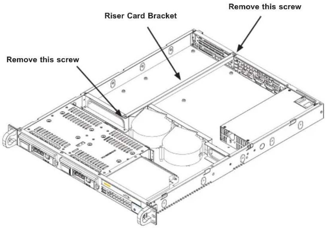
Figure 4-4. Removing the Riser Card Bracket
Installing the Motherboard
- Review the documentation that came with your motherboard. Become familiar with component placement, requirements, precautions, and cable connections.
- Power down the system as described in Section 4-2 and remove the cover.
- Remove the two screws holding the riser card bracket in place.
- Remove the bracket from the chassis.
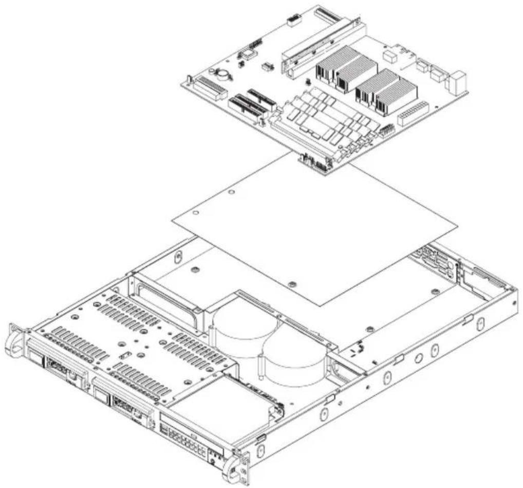
- Locate the mylar sheet in the accessories package and place the sheet into the chassis.
- Carefully place the motherboard in the chassis. You must align the I/O shield with the motherboard ports.
natural_image
Exploded view diagram of a server rack with internal components (no text or labels)Figure 4-5. Installing the Mylar Sheet and Motherboard
- Secure the motherboard to the chassis using six screws located in the chassis screws. Do not exceed eight pounds of torque when tightening down the motherboard.
- Secure the CPU(s), heatsinks, and other components to the motherboard as described in the motherboard documentation.
- Connect the cables between the motherboard, backplane, chassis, front panel, and power supply, as needed.
- Replace the riser card bracket.
4-6 Installing the Expansion Card
The SC811 chassis includes a slot for one full-length/full-height expansion card slot.
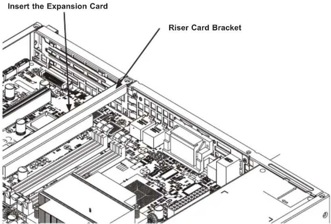
Figure 4-6. Expansion Card Installation
Installing the Expansion Card
- Power down the system as described in Section 4-2, lay the chassis on a flat surface, and open the chassis cover.
- In the rear of the chassis, pull open the expansion card clip and remove the PCI slot shield.
- Confirm that the expansion card has an L-bracket and connect the expansion card to the riser card which is embedded in the riser card bracket.
- When the expansion card is installed in the riser card, the L-bracket slides into the PCI slot. Note that most expansion cards face downward once installed.
- Close the expansion card clip to secure the L-bracket and expansion card.
4-7 Installing the Air Shroud
Air shrouds concentrate airflow to maximize fan efficiency. The SC811 chassis air shroud does not require screws to set it up.
Installing the Air Shroud
- Remove the mylar air shroud from the accessories box.
- If necessary, bend the air shroud so the sides air at a ninety degree angle to the top.
- Place air shroud in the chassis. The air shroud fits behind the two blowers.
Checking the Server Airflow
- Make sure there are no objects to obstruct airflow in and out of the server. In addition, if you are using a front bezel, make sure the bezel's filter is replaced periodically.
- Do not operate the server without drives or drive trays in the drive bays. Use only recommended server parts.
- Make sure no wires or foreign objects obstruct air flow through the chassis. Pull all excess cabling out of the airflow path or use shorter cables.
- The control panel LEDs inform you of system status. See "Chapter 3: System Interface" for details on the LEDs and the control panel buttons.
Installation Complete
In most cases, the chassis power supply and system air blowers are pre-installed. In the unlikely event that it is necessary to replace the blowers or power supply, continue to the following section where general maintenance procedures will be addressed. If the chassis will be installed into a rack, proceed to the next chapter for rack installation instructions.
General Maintenance
The following section provides general maintenance information for the SC811 chassis
4-8 System Blowers
Two heavy-duty air blowers provide cooling for the chassis. These fans circulate air through the chassis as a means of lowering the chassis internal temperature.
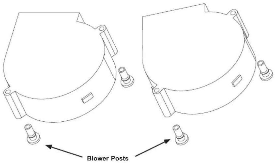
Figure 4-7. Changing System Blowers
Changing a System Blower
- If necessary, open the chassis while the power is running to determine which blower needs to be changed. (Never run the server for an extended period of time with the chassis open.)
- (Optional) Power down the system as described in Section 4-2. This blower can be replaced without stopping the chassis.
- Remove the failed fan's power cord from the serverboard.
- Lift the blower from the chassis.
- Align the replacement blower with the blower post and secure the blower to the chassis.
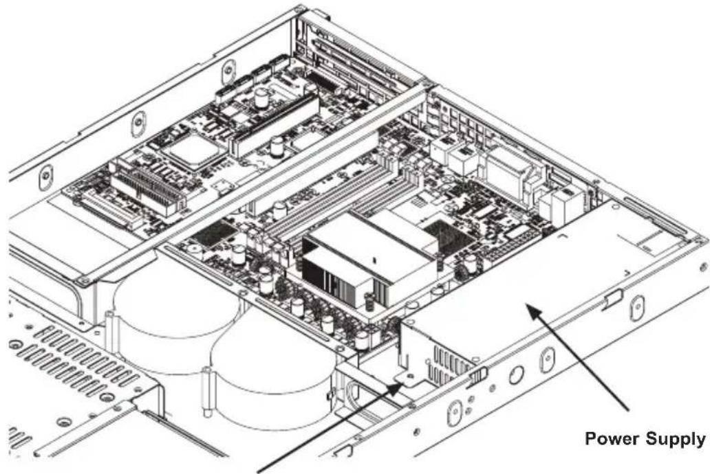
4-9 Power Supply
Most SC811 chassis models include a high-efficiency power supply that is auto-switching capable. This enables it to automatically sense and operate at a 100v to 240v input voltage. An amber light will be illuminated on the power supply when the power is off. An illuminated green light indicates that the power supply is operating.

natural_image
Top-down schematic of a server rack with ports, connectors, and ventilation slots (no text or labels)Remove these screws
Remove this screw
Figure 4-8. Changing the Power Supply
Changing the Power Supply
- Power down the system as described in Section 5-2 and remove the cover.
-
Disconnect all cables connecting the power supply to the motherboard and other components.
-
Remove the three screws securing the power supply. Two screws are accessible from the rear of the chassis. The other is located in the front of the power supply.
- Remove the power supply and replace the unit with out of the same model.
- Reconnect the cables to the motherboard.
- Reconnect the power cord and power-up the system.
4-10 Other Components
Changing the DVD-ROM
- Power down the system as described in Section 4-2 and remove the cover..
- Disconnect the power cord and data cables from the DVD-ROM drive to other chassis components including the motherboard and backplane.
- Remove the failed DVD-ROM drive by depressing the release tab, then pulling the drive out of the chassis.
- Insert the new DVD-ROM drive unit in the slot until the tab locks into place.
- Connect the data cables and power cord to the backplane and motherboard.
- For more information, see the manual for your backplane in the appendix of this document.
Changing the Control Panel
- Power down the system as described in Section 4-2 and remove the cover..
- Disconnect the power cord and data cables from the control panel to other chassis components including the motherboard and backplane.
- Remove the control panel by depressing the release tab (or removing the screws), then pull the unit out of the chassis.
- Insert the new control panel unit into the slot until the tab locks into place.
- Connect the data and power cables to the backplane and motherboard. For more information, see the manual for your backplane in the appendix of this document.
Chapter 5
Rack Installation
This chapter provides simple instructions for installing this chassis into a rack. This chassis does not support Telco rack installation.
5-1 Preparing for Setup
Please read this section in its entirety before beginning the installation procedure.
Choosing a Setup Location
Decide on a suitable location for the rack. It should be a clean, dust-free area that is well ventilated. Avoid areas where heat, electrical noise and electromagnetic fields are generated. Place it near a grounded power outlet.
- Leave at least 25 inches clearance in front of the rack to open the front door completely.
- Leave approximately 30 inches of clearance in the back of the rack to allow for sufficient airflow and ease in servicing.
- Install in a restricted access location, such as a dedicated equipment room or service closet.
Ambient Operating Temperature
If installed in a closed or multi-unit rack assembly, the ambient operating temperature of the rack environment may be greater than the ambient temperature of the room. Install the equipment in an environment compatible with the manufacturer's maximum rated ambient temperature (TMRA).
Adequate Airflow
Equipment should be mounted into a rack so that the amount of airflow required for safe operation is not compromised.
Circuit Overloading
Avoid overloading the power supply circuitry or any overcurrent protection equipment. Use equipment nameplate ratings to calculate your requirements.
Reliable Ground
A reliable ground must be maintained at all times. To ensure this, ground the rack, itself. Pay attention to power supply connections other than the direct connections to the branch circuit, such as power strips.
Physical Rack Precautions

Warning: Follow these guidelines to prevent injury. Take all precautions to ensure the system remains stable. The following guidelines are provided to ensure your safety.
- Ensure that the leveling jacks on the bottom of the rack are fully extended to the floor with the full weight of the rack resting on them.
- In single rack installation, stabilizers should be attached to the rack.
• In multiple rack installations, the racks should be coupled together. - When mounting this unit in a partially filled rack, load the rack from the bottom to the top with the heaviest component at the bottom of the rack. If this is the only unit in the rack, mount it at the bottom.
- Always make sure the rack is stable before extending a component from the rack. Extend only one component at a time. Extending two or more simultaneously may cause the rack to become unstable.
• This chassis does not support Telco rack installation.
General Server Precautions
-
Review the electrical and general safety precautions that came with the components you are adding to your chassis.
• Determine the placement of each component in the rack. -
Install the heaviest server components on the bottom of the rack first, and then work up.
- Use a regulating, uninterruptible power supply (UPS) to protect the server from power surges, voltage spikes and to keep your system operating in case of a power failure.
- Allow the hard drives and power supply modules to cool before touching them.
- Always keep the rack front door, all panels and all components on the servers closed when not servicing, to maintain proper cooling.
5-2 Rack Mounting Instructions
This section provides information on installing the SC811 chassis into a rack unit with the rails provided. There are a variety of rack units on the market, which may mean the assembly procedure will differ slightly. Refer also to the installation instructions that came with the rack unit.
Note: The rails will fit a rack between 29" and 35.25" deep.
Identifying the Sections of the Rails
The chassis package includes two rail assemblies in the rack mounting kit. Each assembly consists of two sections: an inner fixed chassis rail that secures directly to the server chassis and an outer rack rail that secures directly to the rack itself.
Rail Brackets
The chassis package includes four rail brackets and two chassis mounts. The rail brackets have long ovals used to adjust the length of the rails when mounting. The chassis mounts (both short) have one square hole.
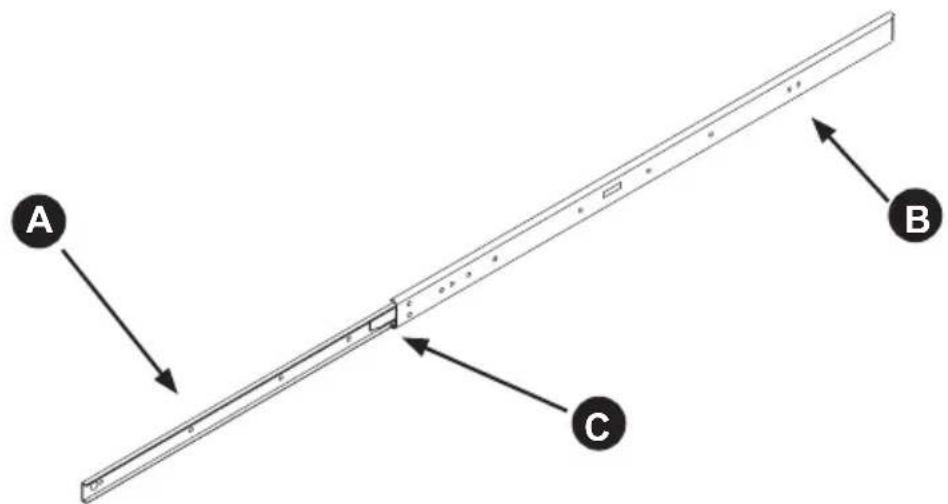
Figure 5-1: Inner and Outer Rails
Separating the Inner and Outer Rails
- Pull the inner rail (A) from the outer rail (B) as far as possible.
- Depress the locking tab (C) to pull the inner rail completely out.
- Repeat steps 1 and 2 for the other rail.
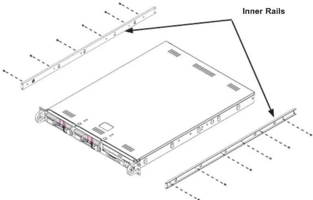
Figure 5-2: Rail Installation
Installing the Inner Rail
- Align the chassis rail with the side of the chassis.
- Secure the rail to the chassis using six M5 flat head screws.
- Repeat steps 1 and 2 for the other side of the chassis.
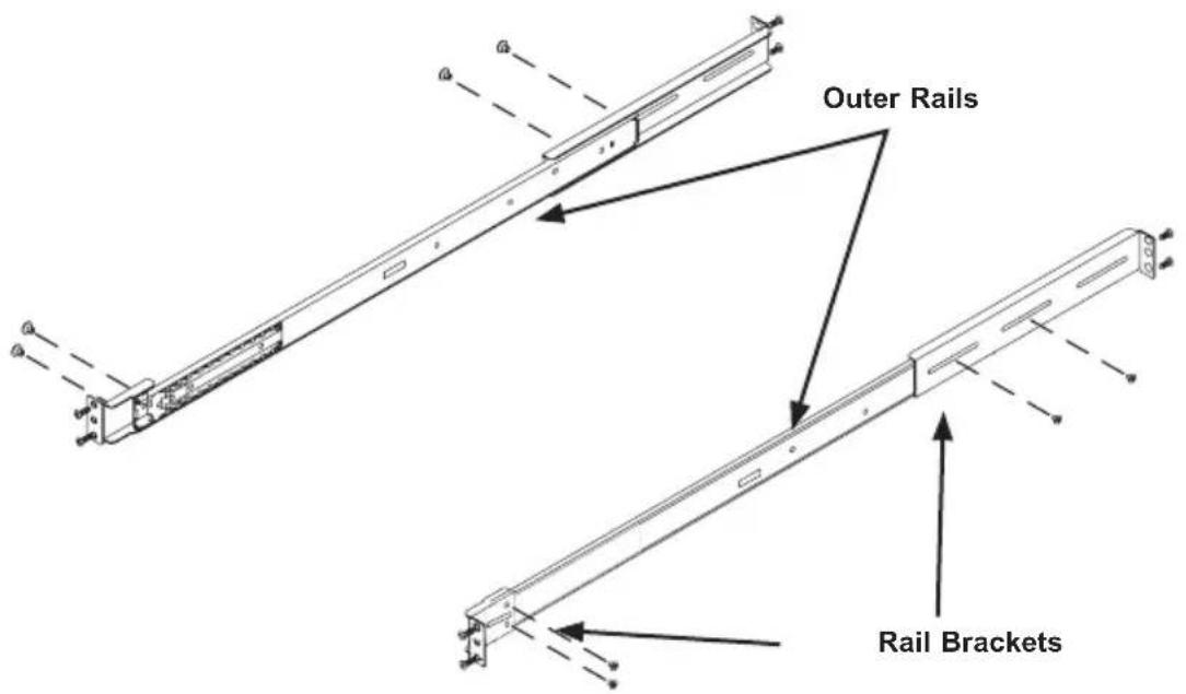
Figure 5-3. Rack Brackets
Installing the Outer Rails to the Rack
- Confirm that the inner rails have been separated from the outer rails.
- Locate the rail brackets in the accessories box. The chassis package includes four rail brackets and two chassis mounts. The rail brackets have long ovals used to adjust the position of the rails when mounting. The chassis mounts (both short) have one square hole.
- Secure the short brackets to the front of the outer rails with two M4 screws.
- Secure the long brackets to the outer rails using two M4 screws. Tighten the screws loosely so the bracket can slide back and forth.
- Position the outer rail and brackets in the rack at the desired level.
- Secure the front of the rail to the rack using two M5 rack screws.
- Slide the rear bracket so that it snugly fits into the rack. Secure the rear bracket to the rack using two M5 screws.
- Tighten the screws that secure the rear bracket to the rail.
- Repeat these steps with the other chassis rail.

Stability hazard. The rack stabilizing mechanism must be in place, or the rack must be bolted to the floor before you slide the unit out for servicing. Failure to stabilize the rack can cause the rack to tip over.
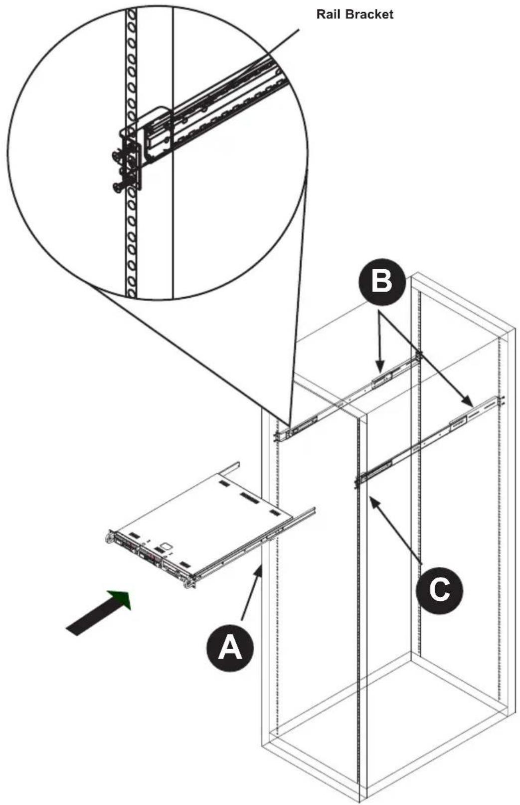
Figure 5-4: Mounting the Chassis
(Note: This figure is for illustrative purposes only. Always install servers into racks from the bottom up.
Installing the Chassis into a Rack
Chassis Installation
- Confirm that the chassis includes the inner rails (A) and that the outer rails (B) are installed on the rack (See Figure 5-3)
- Align the chassis rails (A) with the front of the rack rails (C).
- Slide the chassis rails into the rack rails, keeping the pressure even on both sides (you may have to depress the locking tabs when inserting). When the server has been pushed completely into the rack, you should hear the locking tabs "click".
- (Optional) Insert and tightening the thumbscrews that hold the front of the server to the rack.

Caution: Do not pick up the server by the front handles. They are designed to pull the system from a rack only.
Notes
Appendix A
Cables, Screws, and Other Accessories
A-1 Overview
This appendix lists supported cables for your chassis system. It only includes the most commonly used components and configurations. For more compatible cables, refer to the manufacturer of the motherboard you are using and our Web site at: www.supermicro.com.
A-2 Cables Included with SC811TQ Chassis (SAS/SATA)
| SC811TQ | |||
| Part # Type | Length Description | ||
| CBL-00051L Cable | 60 cm Round | floppy cable | |
| CBL-0061L | Ribbon, round | 35 cm SATA | A cable |
| CBL-0155L Wire 60 | cm IDE 80 | -wire cable for DVD-ROM | |
| - Cord 6 feet | Regional power cord | ||
| CBL-0157L Cable | Varies 8-pin to 8-pin cable for SGPIO | ||
Note: Items may change without notice. Refer to http://www.supermicro.com for the latest information.
A-3 Cables Included with SC811S Chassis (SCSI)
| SC811S | |||
| Part # Type | Length Description | ||
| CBL-0051L | Cable 60 | cm Round floppy cable | |
| CBL-0052 | Cable 60 | cm Round IDE cable | |
| CBL-0063 | Cable 20 | inches SCSI cable | |
| - Cord 6 feet Regional | power cord | ||
| CBL-0155L | Cable 60 | cm 80-wire IDE from DVD-ROM | |
Note: Items may change without notice. Refer to http://www.supermicro.com for the latest information.
A-4 Cables Included with the SC811T Chassis (SCSI)
| SC811T | |||
| Part # Type | Length Description | ||
| CBL-0061 Cable 1 | 3.8 inches A | Amphenol Serial | ATA cable |
Note: Items may change without notice. Refer to http://www.supermicro.com for the latest information.
A-5 Compatible Cables
These cables are compatible with the SC811 chassis.
Alternate SAS/SATA Cables
Some compatible motherboards have different connectors. If your motherboard has only one SAS connector that the SAS/SATA cables must share, use one of the following cables. These cables must be purchased separately.
Cable Name: SAS Cable Quantity: 1
Part #: CBL-0175L
Alt. Name: "Big Four"
Description: This cable has one SFF-8484 (32-pin) connector on one end and four SAS connectors (with seven pins each) at the other. This cable connects from the host (motherboard or other controller) to the backplane's SAS hard drive port.
Cable Name: SAS Cable Quantity: 1
Part #: CBL-0116
Alt. Name: iPass or "Small Four"
Description: This cable has one iPass (SFF-8087/Mini-SAS) connector (36-pin) at one end and four SAS connectors on one end. This cable connects from the host (motherboard or other controller) to the backplane's SAS hard drive port.
Extending Power Cables
Although Supermicro chassis are designed with to be efficient and cost-effective, some compatible motherboards have power connectors located in different areas.
To use these motherboards you may have to extend the power cables to the mother boards. To do this, use the following chart as a guide.
| Power Cable Extenders | ||
| Number of Pins Cable Part # Length | ||
| 24-pin CBL-0042 | 7.9" (20 cm) | |
| 20-pin CBL-0059 | 7.9" (20 cm) | |
| 8-pin CBL-0062 | 7.9" (20 cm) | |
| 4-pin CBL-0060 | 7.9" (20 cm) | |
Front Panel to the Motherboard
The SC811 chassis includes a cable to connect the chassis front panel to the motherboard. If your motherboard uses a different connector, use the following list to find a compatible cable.
| Front Panel to Motherboard Cable (Ribbon Cable) | ||
| Number of Pins(Front Panel) | Number of Pins(Motherboard | Cable Part # |
| 16-pin 16-pin CBL-0049 | ||
| 16-pin 20-pin CBL-0048 | ||
| 20-pin 20-pin CBL-0047 | ||
| 16-pin varies* CBL-0068 | ||
| 20-pin varies* CBL-0067 | ||
* Split cables: Use these cable if your motherboard requires several different connections from the front panel.
A-6 Chassis Screws
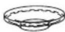
The chassis and accessory box include all the screws needed to set up your chassis. This section includes descriptions of the most common screws used. Your chassis may not require all of the parts listed.
M/B

Pan head 6-32 x 5 mm [0.197]
HARD DRIVE

Flat head 6-32 x 5 mm [0.197]
DVD-ROM, CD-ROM, and FLOPPY DRIVE

Pan head 6-32 x 5 mm [0.197]

Flat head 6-32 x 5 mm [0.197]

Round head 3 x 5 mm [0.197]

Round head 2.6 x 5 mm [0.197]
RAIL

Flat head M4 x 4 mm [0.157]
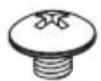
Round head M4 x 4 mm [0.157]
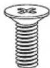
Flat head M5 x 12 mm[0.472] Washer for M5
M/B STANDOFFS
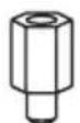
M/B standoff 6-32 to 6-32
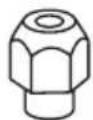
M/B (CPU) standoff M5 to 6-32
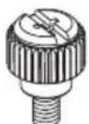
Thumb screw 6-32 x 5 mm [0.197]
Appendix B
SC811 Power Supply Specifications
This appendix lists power supply specifications for your chassis system.
| 600W | |
| MFR Part # PWS | -601-1H |
| Rated AC Voltage | 100 - 240V50 - 60Hz7.5 - 3.1A |
| +5V standby | 3A |
| +12V | 49 Amp |
| +5V | 20 Amp |
| +3.3V | 16 Amp |
| -12V | 0.5 Amp |
| 520W 420W | ||
| MFR Part # PWS | -521-1H PWS-0053 | |
| Rated AC Vol-t-age | 100 - 240V, 50 - 60Hz,7 - 3 Amp | 100 - 240V, 60/50Hz, 7Amp |
| DC Output | --- 5V + 3.3V ≤ 120W | |
| +5V standby | 3 Amp 2.0 Amp | |
| +12V | 39 Amp --- | |
| +12V _1 | --- 15.0 Amp | |
| +12V _2 | --- 15.0 Amp | |
| +12V _3 | --- 18.0 Amp | |
| +5V | 20 A 30.0 Amp | |
| +3.3V | 16 Amp 20.0 Amp | |
| -12V | 0.5 Amp 1.0 Amp | |
SC811 Chassis Manual
| 410W 350W | ||
| MFR Part # PWS | -0061 PWS-0042-24 | |
| Rated AC Vol-t-age | --- 100 - 240V, 60-50Hz, 6 Amp | |
| DC Output | --- | 5V + 3.3V ≤ 157W• 12V + 5V + 3.3V ≤ 330W |
| DC Voltage | Voltage Range = -36V to -72VNominal Voltage = -48VMax Input Current = 18A @ -48V | --- |
| +5V standby | 3.0 Amp 2.0 Amp | |
| +12V | 39 Amp 25.0 Amp | |
| +5V | 32.0 Amp 25.0 Amp | |
| +3.3V | 20 Amp 20.0 Amp | |
| -12V | 0.5 Amp 0.8 Amp |
| 300W 280W | ||
| MFR Part # PWS | -0054 PWS-281-1H | |
| Rated AC Voltage | 100 - 240V, 60-50Hz, 5 Amp | 100 - 240V, 50 - 60Hz, 5Amp |
| DC Output | 5V + 3.3V ≤ 100W | |
| +5V standby | 2.0 Amp 2 Amp | |
| +12V | 24.0 Amp 23 Amp | |
| +5V | 25 Amp 18 Amp | |
| +3.3V | 15 Amp 15 Amp | |
| -12V | 1.0 Amp 1.0 Amp | |
| 260W | |
| MFR Part # PWS | -0055 |
| Rated AC Voltage | 100 - 240V, 60-50Hz, 4 Amp Max |
| DC Output | 5V + 3.3V ≤ 140W |
| +5V standby | 2.0 Amp |
| +12V | 18.0 Amp |
| +5V | 25.0 Amp |
| +3.3V | 15.0 Amp |
| -12V | 1.0 Amp |
Appendix C
SAS-810TQ Backplane Specifications
To avoid personal injury and property damage, carefully follow all the safety steps listed below when accessing your system or handling the components.
C-1 ESD Safety Guidelines
Electrostatic Discharge (ESD) can damage electronic components. To prevent damage to your system, it is important to handle it very carefully. The following measures are generally sufficient to protect your equipment from ESD.
- Use a grounded wrist strap designed to prevent static discharge.
- Touch a grounded metal object before removing a component from the antistatic bag.
- Handle the backplane by its edges only; do not touch its components, peripheral chips, memory modules or gold contacts.
- When handling chips or modules, avoid touching their pins.
- Put the backplane and peripherals back into their antistatic bags when not in use.
C-2 General Safety Guidelines
- Always disconnect power cords before installing or removing any components from the computer, including the SAS-810TQ backplane.
- Disconnect the power cable cord installing or removing any cables from the SAS-810TQ backplane.
- Make sure that the SAS-810TQ backplane is securely and properly installed to prevent damage to the system due to power shortage.
C-3 An Important Note to Users
All images and layouts shown in this user's guide are based upon the latest PCB revision available at the time of publication. The card you have received may or may not look exactly the same as the graphics shown in this manual.
C-4 Introduction to the SAS-810TQ Backplane
The SAS-810TQ backplane has been designed to utilize the most up-to-date technology available, providing your system with reliable, high-quality performance.
This manual reflects SAS-810TQ Revision 1.00, the most current release available at the time of publication. Always refer to the Supermicro Web site at www.supermicro.com for the latest updates, compatible parts and supported configurations.
C-5 Front Connectors
flowchart
graph TD
    A["Room 1"] --> B["Building Area"]
    B --> C["Building Area"]
    C --> D["Building Area"]
    D --> E["Building Area"]
    E --> F["Building Area"]
    F --> G["Building Area"]
    G --> H["Building Area"]
    H --> I["Building Area"]
    I --> J["Building Area"]
    J --> K["Building Area"]
    K --> L["Building Area"]
    L --> M["Building Area"]
    M --> N["Building Area"]
    N --> O["Building Area"]
    O --> P["Building Area"]
    P --> Q["Building Area"]
    Q --> R["Building Area"]
    R --> S["Building Area"]
    S --> T["Building Area"]
    T --> U["Building Area"]
    U --> V["Building Area"]
    V --> W["Building Area"]
    W --> X["Building Area"]
    X --> Y["Building Area"]
    Y --> Z["Building Area"]
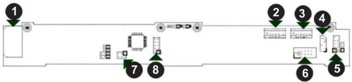
Figure C-1: Front Connectors
Front Connectors
1. Power connector, 4-pin, JP10
2. SAS port 1, J6
3. SAS port 0, J5
4. I²C connector, JP44
5. Sideband, JP51
6. Activity LED header, JP26
7. Upgrade, JP46
8. JTAG, JP47
C-6 Front Connectors and Pin Definitions
#1. Backplane Main Power Connectors
The 4-pin connector designated JP10, provides power to the backplane. See the table on the right for pin definitions.
| BackplaneMain Power4-Pin Connector(JP10) | |
| Pin# | Definition |
| 1 | +12V |
| 2 and 3 | Ground |
| 4 +5V | |
#2., #3. SAS Ports
The SAS ports are used to connect the SAS drive cables.
| SAS PortPin Definitions | ||
| Pin # | Definition Pin # | Definition |
| 1 Ground 2 TXP | ||
| 3 TXN 4 Ground | ||
| 5 RXN 6 RXP | ||
| 7 Ground | ||
#4. I²C Connector
The I²C Connector, designated JP44, is used to monitor HDD activity and status. See the table on the right for pin definitions.
| PC ConnectorPin Definitions(JP44) | |
| Pin# | Definition |
| 1 Data | |
| 2 Ground | |
| 3 Clock | |
| 4 No Connection | |
#5. Sideband Header
The sideband header is designated JP51. I²C is the default mode setting. For SES-2 to work properly, you must connect an 8-pin sideband cable. See the table to the right for pin definitions.
| Sideband Headers(JP51) | |
| Pin # Definition Pin # Definition | |
| 2 SGPIO:SDIN;PC:BackplaneAddressing(SB5) | 1 ControllerID (SB6) |
| 4 SGPIO:SDOUT;PC: Reset(SB4) | 3 GND (SB2) |
| 6 GND (SB3) 5 SGPIO: | SLOAD;PC: SDA(SB1) |
| 8 BackplaneID (SB7) | 7 SGPIO:SCLOCK;12C: SCL(SB0) |
| 10 No Connec-tion | 9 No Connec-tion |
#6. Activity LED Header
The activity LED header, designated JP26 is used to indicate the activity status of each SAS drive. The activity LED is located on the front panel. For the activity lead headers to work properly, connect to them using a 10-pin LED cable. This is only used when the activity LED is not supported by the hard drive.
| SAS Activity LED HeaderPin Definitions (JP26) | |
| Pin # Definition Pin # Definition | |
| 1 ACT IN#0 6 NC | |
| 2 ACT IN#1 7 NC | |
| 3 NC 8 NC | |
| 4 NC 9 NC | |
| 5 NC 10 Empty | |
NC = No Connection
#7. Upgrade Connector
The upgrade connector, designated JP46 is used for manufacturer's diagnostic purposes only.
#8. JTAG
The JTAG port, designated JP47, is a signed debugging port.
C-7 Front Jumper Locations and Pin Definitions

Figure C-2: Front Jumpers
Explanation of Jumpers
To modify the operation of the backplane, jumpers can be used to choose between optional settings. Jumpers create shorts between two pins to change the function of the connector. Pin 1 is identified with a square solder pad on the printed circuit board. Note: On two pin jumpers, "Closed" means the jumper is on and "Open" means the jumper is off the pins.
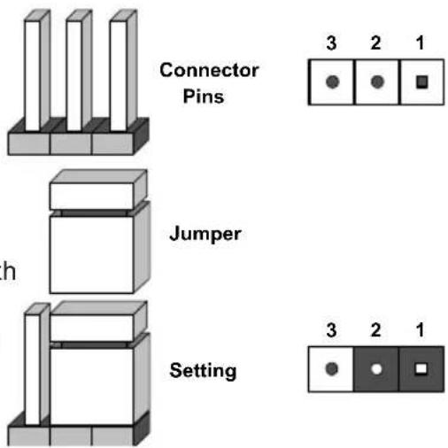
| Jumper Settings | ||
| Jumper Jumper Settings Note | ||
| JP18 | Open: DefaultClosed: Reset | NormalBuzzer reset* |
| JP29 | Open: DefaultClosed: Reset | NormalMG9071 chip reset |
*The buzzer sound indicates that a condition requiring immediate attention has occurred.
The buzzer alarm is triggered by the following conditions:
- Hard drive failure
- Fan failure
- System temperature over 45° Celsius.
I²C and SGPIO Modes and Jumper Settings
This backplane can utilize ⌊C or SGPIO. SGPIO is the default mode and can be used without making changes to your jumpers. The following information details which jumper must be configured to use SGPIO mode or restore your backplane to ⌊C mode.
| Jumper Settings: SGPIO and I2C (Default) | ||
| Jumper SGPIO Setting I | 2C Setting (Default) | |
| JP33: CTRL_ID Pins1-2: | SGPIO mode enabled 2-3: I | 2C mode enabled |
| JP40: I2CRST_SDOUT On: | SGPIO mode enabled Off: I | 2C mode enabled |
| JP42: BPID_SDIN Pins 1-2: | SGPIO mode enabled 2-3: I | 2C mode enabled |
| JP50: I2CRST Off: SGPIO mode enabled On: I | 2C mode enabled | |
| Jumper Settings: Backplane ID | |
| Jumper I | ^2C Backplane ID Settings |
| JP34: BP_ID Pins 1 | -2: ID#0 (Default) Pins 2-3: ID#1 |
Front LED Indicators

Figure C-3: Front LEDs
| Front Panel LEDs | ||
| LED State | Specification | |
| Alarm #1 (D3) On Overheat/drive failure. | ||
C-8 Rear Connectors and LED Indicators

Figure C-4: Rear Connectors and LEDs
| Rear SAS/SATA Connectors | |
| Rear Connector SAS/SATA Drive Number | |
| SAS #0 (J1) SAS/SATA HHD #0 | |
| SAS #1 (J0) SAS/SATA HHD #1 | |
| Rear LED Indicators | ||
| Rear LED Hard Drive Activity Failure LED | ||
| SAS #0 D12 D5 | ||
| SAS #1 D13 D6 | ||
Notes
Appendix D
SATA-810 Backplane Specifications
To avoid personal injury and property damage, carefully follow all the safety steps listed below when accessing your system or handling the components.
D-1 ESD Safety Guidelines
Electrostatic Discharge (ESD) can damage electronic components. To prevent damage to your system, it is important to handle it very carefully. The following measures are generally sufficient to protect your equipment from ESD.
- Use a grounded wrist strap designed to prevent static discharge.
- Touch a grounded metal object before removing a component from the antistatic bag.
- Handle the backplane by its edges only; do not touch its components, peripheral chips, memory modules or gold contacts.
- When handling chips or modules, avoid touching their pins.
- Put the card and peripherals back into their antistatic bags when not in use.
D-2 General Safety Guidelines
- Always disconnect power cables before installing or removing any components from the computer, including the backplane.
- Disconnect the power cable before installing or removing any cables from the backplane.
- Make sure that the backplane is securely and properly installed on the motherboard to prevent damage to the system due to power shortage.
D-3 An Important Note to Users
All images and layouts shown in this user's guide are based upon the latest PCB Revision available at the time of publishing. The card you have received may or may not look exactly the same as the graphics shown in this manual.
D-4 Introduction to the SATA-810 Backplane
The SATA-810 backplane has been designed to utilize the most up-to-date technology available, providing your system with reliable, high-quality performance.
This manual reflects SATA-810 Revision 2.0, the most current release available at the time of publication. Always refer to the Supermicro Web site at www.supermicro.com for the latest updates, compatible parts and supported configurations.
D-5 Front Connectors
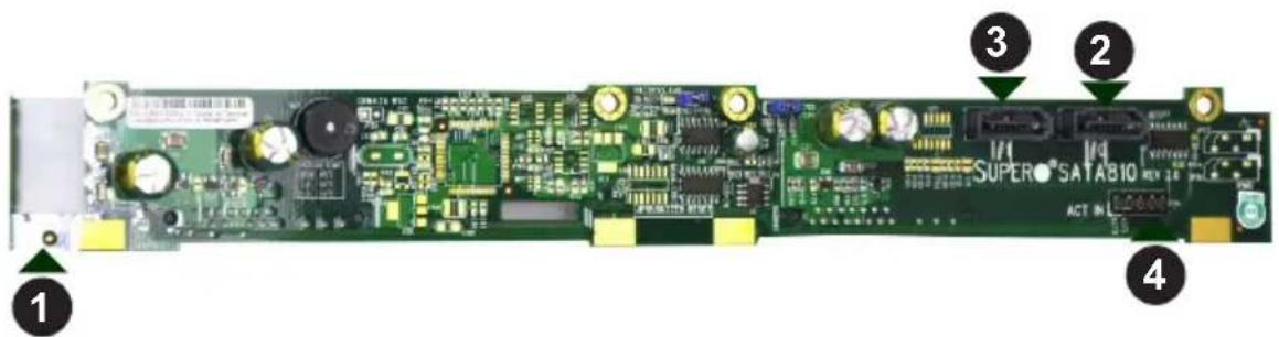
Figure D-1: Front Connectors
Front Connectors
- Power connector: JP10
- SATA cable connector #0: J5
- SATA cable connector #1: J6
- ACT_IN: JP26
D-6 Front Connector Definitions
1. Main Power Connector
The power connector is designated JP10. The main power connector provides power to the backplane.
2. - 3. SATA Cable Connectors
The SATA cable connectors are designated J5 and J6.
4. Activity LED Connector
The activity LED connector, designated JP26, is used to indicate the activity status of each SATA drive. The activity LED connector is located on the front panel. In order for the activity LED header to work properly, connect using a 10-pin LED cable.
| SATA Activity LED HeaderPin Definitions | |
| Pin # Definition Pin # Definition | |
| 1 ACT IN#0 6 ACT IN#4 | |
| 2 ACT IN#1 7 ACT IN#5 | |
| 3 ACT IN#2 8 ACT IN#6 | |
| 4 ACT IN#3 9 ACT IN#7 | |
| 5 Ground 10 Empty |
D-7 Front Jumper Locations and Pin Definitions

Figure D-2: Front Jumpers
| Socket Settings | ||
| Jumper Setting Note | ||
| JP18 | Open: No reset (Default)Closed: Reset | Buzzer reset* |
| JP25 | Open: 45°C | Overheat temperature setting |
| Pins 1-2: 50°C (Default) | ||
| Pins 2-3: 55°C | ||
Explanation of Jumpers
To modify the operation of the backplane, jumpers can be used to choose between optional settings. Jumpers create shorts between two pins to change the function of the connector. Pin 1 is identified with a square solder pad on the printed circuit board. Note: On two pin jumpers, "Closed" means the jumper is on and "Open" means the jumper is off the pins.

*The buzzer sound indicates that a condition requiring immediate attention has occurred.
The buzzer alarm is triggered by the following condition:
System temperature over 50° Celsius.
Front LED Indicator

Figure D-3: Front LED
| Front LED | ||
| LED Normal State Indicator Status | ||
| Overheat LED: D3 Off | Red indicator light is on when an overheat condition occurs. | |
D-8 Rear Connectors and LED Indicators
Rear Connectors
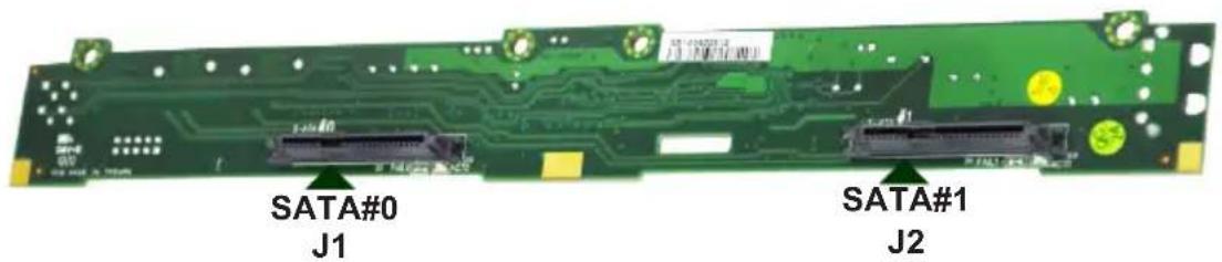
Figure D-4: Rear Connectors
| Rear Connectors | |
| Rear Connector SATA Drive Number | |
| SATA #0 (J1) SATA HDD #0 | |
| SATA #1 (J2) SATA HDD #1 |
Rear LEDs
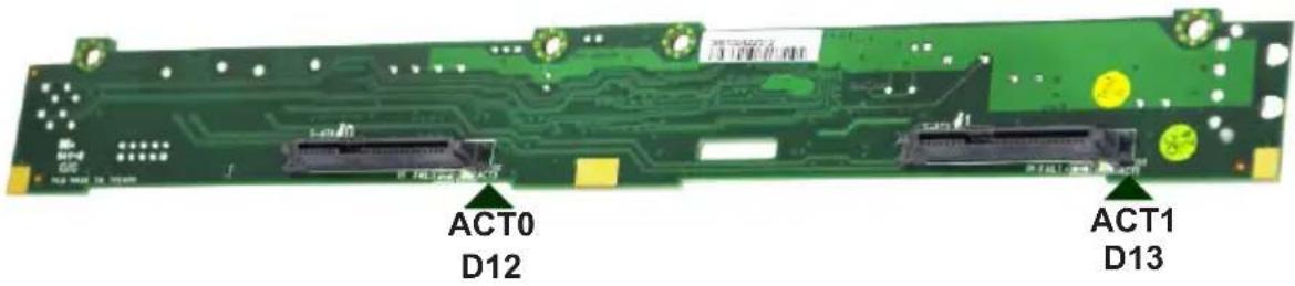
Figure D-5: Rear LEDs
| Rear LED Inidcators | ||
| Activity LED Designation SATA Drive Number | ||
| ACT0 D12 SATA HDD #0 | ||
| ACT1 D13 SATA HDD #1 | ||
Notes
Disclaimer (cont.)
The products sold by Supermicro are not intended for and will not be used in life support systems, medical equipment, nuclear facilities or systems, aircraft, aircraft devices, aircraft/emergency communication devices or other critical systems whose failure to perform be reasonably expected to result in significant injury or loss of life or catastrophic property damage. Accordingly, Supermicro disclaims any and all liability, and should buyer use or sell such products for use in such ultra-hazardous applications, it does so entirely at its own risk. Furthermore, buyer agrees to fully indemnify, defend and hold Supermicro harmless for and against any and all claims, demands, actions, litigation, and proceedings of any kind arising out of or related to such ultra-hazardous use or sale.
- WARNING: Handling of lead solder materials used in this product may expose you to lead, a chemical known to the State of California to cause birth defects and other reproductive harm.
- Preface
- About This Manual
- Manual Organization
- Chapter 1 Introduction
- Chapter 2 Warning Statements for AC Systems
- Chapter 3 System Interface
- Chapter 4 Chassis Setup and Maintenance
- Chapter 5 Rack Installation
- Contents
- Chapter 2 Standardized Warning Statements for AC Systems
- Appendix A Cables, Screws, and Other Accessories
- Appendix B SC811 Power Supply Specifications
- Appendix C SAS-810TQ Safety Guidelines
- Connectors and Jumpers
- Appendix D SATA-810 Backplane Specifications
- Notes
- Chapter 1
- Introduction
- 1-1 Overview
- 1-2 Shipping List
- Part Numbers
- 1-3 Contacting Supermicro
- Headquarters
- Asia-Pacific
- 1-4 Unpacking the System
- 1-5 Returning Merchandise for Service
- 1-6 Where to get Replacement Components
- Chapter 2
- Standardized Warning Statements for AC Systems
- 2-1 About Standardized Warning Statements
- Warning Definition
- Warning!
- Installation Instructions
- Power Disconnection Warning
- Equipment Installation
- 機器の設置
- Redundant Power Supplies
- 冗長電源装置
- Comply with Local and National Electrical Codes
- Power Cable and AC Adapter
- 3-2 Control Panel Buttons
- 3-3 Control Panel LEDs
- 3-4 Drive Carrier LEDs
- SAS/SATA Drives
- SCSI Drives
- Chapter 4
- Chassis Setup and Maintenance
- 4-1 Overview
- 4-2 Removing the Power from the System
- 4-3 Removing the Chassis Cover
- Removing the Chassis Cover
- 4-4 Removing and Installing Hard Drives
- Removing Hard Drive Trays from the Chassis
- Installing a Hard Drive
- 4-5 Installing the Motherboard
- Installing the Motherboard
- 4-6 Installing the Expansion Card
- Installing the Expansion Card
- 4-7 Installing the Air Shroud
- Installing the Air Shroud
- Checking the Server Airflow
- Installation Complete
- General Maintenance
- 4-8 System Blowers
- Changing a System Blower
- 4-9 Power Supply
- Changing the Power Supply
- 4-10 Other Components
- Changing the DVD-ROM
- Changing the Control Panel
- Chapter 5
- Rack Installation
- 5-1 Preparing for Setup
- Choosing a Setup Location
- Ambient Operating Temperature
- Adequate Airflow
- Circuit Overloading
- Reliable Ground
- Physical Rack Precautions
- General Server Precautions
- 5-2 Rack Mounting Instructions
- Identifying the Sections of the Rails
- Rail Brackets
- Separating the Inner and Outer Rails
- Installing the Inner Rail
- Installing the Outer Rails to the Rack
- Installing the Chassis into a Rack
- Chassis Installation
- Appendix A
- Cables, Screws, and Other Accessories
- A-1 Overview
- A-4 Cables Included with the SC811T Chassis (SCSI)
- A-5 Compatible Cables
- Alternate SAS/SATA Cables
- Extending Power Cables
- Front Panel to the Motherboard
- A-6 Chassis Screws
- Appendix B
- SC811 Power Supply Specifications
- Appendix C
- SAS-810TQ Backplane Specifications
- C-1 ESD Safety Guidelines
- C-2 General Safety Guidelines
- C-3 An Important Note to Users
- C-4 Introduction to the SAS-810TQ Backplane
- C-5 Front Connectors
- Front Connectors
- Power connector, 4-pin, JP10
- SAS port 1, J6
- SAS port 0, J5
- I²C connector, JP44
- Sideband, JP51
- Activity LED header, JP26
- Upgrade, JP46
- JTAG, JP47
- C-6 Front Connectors and Pin Definitions
- #1. Backplane Main Power Connectors
- #2., #3. SAS Ports
- #4. I²C Connector
- #5. Sideband Header
- #6. Activity LED Header
- #7. Upgrade Connector
- #8. JTAG
- C-7 Front Jumper Locations and Pin Definitions
- Explanation of Jumpers
- The buzzer alarm is triggered by the following conditions:
- I²C and SGPIO Modes and Jumper Settings
- C-8 Rear Connectors and LED Indicators
- Appendix D
- SATA-810 Backplane Specifications
- D-1 ESD Safety Guidelines
- D-2 General Safety Guidelines
- D-3 An Important Note to Users
- D-4 Introduction to the SATA-810 Backplane
- D-5 Front Connectors
- D-6 Front Connector Definitions
- Main Power Connector
- - 3. SATA Cable Connectors
- Activity LED Connector
- D-7 Front Jumper Locations and Pin Definitions
- Front LED Indicator
- D-8 Rear Connectors and LED Indicators
- Rear LEDs
- Disclaimer (cont.)
Brand : Supermicro
Model : SuperChassis SC811
Category : PC Case