
Column Outdoor CH205MB - Heating Gasmate - Free user manual and instructions
Find the device manual for free Column Outdoor CH205MB Gasmate in PDF.


| Product Type | Outdoor Patio Heater |
| Model | Column Outdoor CH205MB |
| Brand | Gasmate |
| Fuel Type | Propane (LPG) |
| Gas Consumption | 35 MJ/h |
| Operating Pressure | 2.75 kPa |
| Injector Size | 1.9 mm |
| Height | 1888 mm |
| Base Diameter / Width | 760 mm (width) / 540 mm (base) |
| Heat Output | 35 MJ/h (approx. 33,000 BTU/h) |
| Ignition | Rotary piezo ignition |
| Safety Features | Tip-over switch, oxygen depletion system, thermocouple |
| Burner Material | Stainless steel |
| Included Accessories | Hose assembly with POL regulator |
| Cylinder Requirement | Standard 9 kg propane cylinder with approved connection |
| Operational Runtime | Approximately 10 hours on a full 9 kg cylinder |
| Clearance to Combustibles | Side: 500 mm, Rear: 500 mm, Ceiling: 500 mm, Below: 500 mm |
| Usage Location | Outdoor only, well-ventilated area |
| Certification | Gas certified to Australian standards |
Frequently Asked Questions - Column Outdoor CH205MB Gasmate
User questions about Column Outdoor CH205MB Gasmate
0 question about this device. Answer the ones you know or ask your own.
Ask a new question about this device
Download the instructions for your Heating in PDF format for free! Find your manual Column Outdoor CH205MB - Gasmate and take your electronic device back in hand. On this page are published all the documents necessary for the use of your device. Column Outdoor CH205MB by Gasmate.
USER MANUAL Column Outdoor CH205MB Gasmate
Model No. CH205MBODS
■ The ideal solution for extending the season of outdoor entertaining
■ Creates a stylish and attractive ambience
■ Rotary piezo ignition
■ Includes a safety ‘tip-over’ switch that halts supply of gas to the unit should it be accidentally knocked over
■ Oxygen depletion system for enhanced safety
■ Stainless steel burner for extra long-term reliability
■ Complete with hose and POL regulator
■ Efficient and powerful 35MJ/h output
■ Adjustable heat output
■ Operates for approximately 10 hours on a properly filled 9Kg Propane cylinder
■ For outdoor use only
■ Gas certified to Australian standards
FOR YOUR SAFETY
If you smell gas:
- Shut off the gas to the appliance.
- Extinguish any open flame.
- If odour continues, immediately call your gas supplier.
Do not store or use gasoline or other flammable vapour and liquids in the vicinity of this or any other appliance.
FOR OUTDOOR USE ONLY
PROPANE GAS
WARNING
Improper installation, adjustment, alteration, service or maintenance can cause injury or property damage.
Read the instructions thoroughly before installing or servicing this equipment.

natural_image
Black cylindrical industrial fan or heater with mesh grille and side vent, no visible text or symbolsImportant: Retain these instructions for future use.
INSTALLATION, OPERATION & MAINTENANCE INSTRUCTIONS

IMPORTANT SAFETY RULES
This appliance must only be used in a well ventilated area.
- This appliance shall not be installed or used indoors, in buildings, garages or any other enclosed area.
- DO NOT place articles on or against this appliance.
- DO NOT use or store flammable materials near this appliance.
- Children and adults should be alerted to the hazards of high surface temperatures, burns and clothing ignition.
- Children should be carefully supervised when they are in the area of the appliance.
- NEVER hang anything including clothes or other flammable items on the appliance.
- DO NOT operate this appliance unless it is fully assembled with burner guard in place.
- DO NOT SPRAY AEROSOLS IN THE VICINITY OF THIS APPLIANCE WHILE IT IS IN OPERATION.
- Installation and repair should be done by a qualified service person. The appliance must be inspected before use and at least annually by a qualified service person. It is imperative that control compartment, burners and circulating air passages of the heater be kept clean.
Prior to assembling your appliance, the following must be reviewed. Compliance with the following should result in satisfactory heater operation. This instruction manual should be retained for future reference. The installation must conform with local codes or authority having jurisdiction.
- The appliance is intended for heating residential and non-residential outdoor spaces. The installation must conform with local codes or, in the absence of local codes, with the Australian Standard AS 5601.
- Adequate clearance around air openings into the combustion chamber, clearances from combustible materials, provisions for accessibility and for combustion and ventilating air supply must be maintained at all times when the appliance is operating.
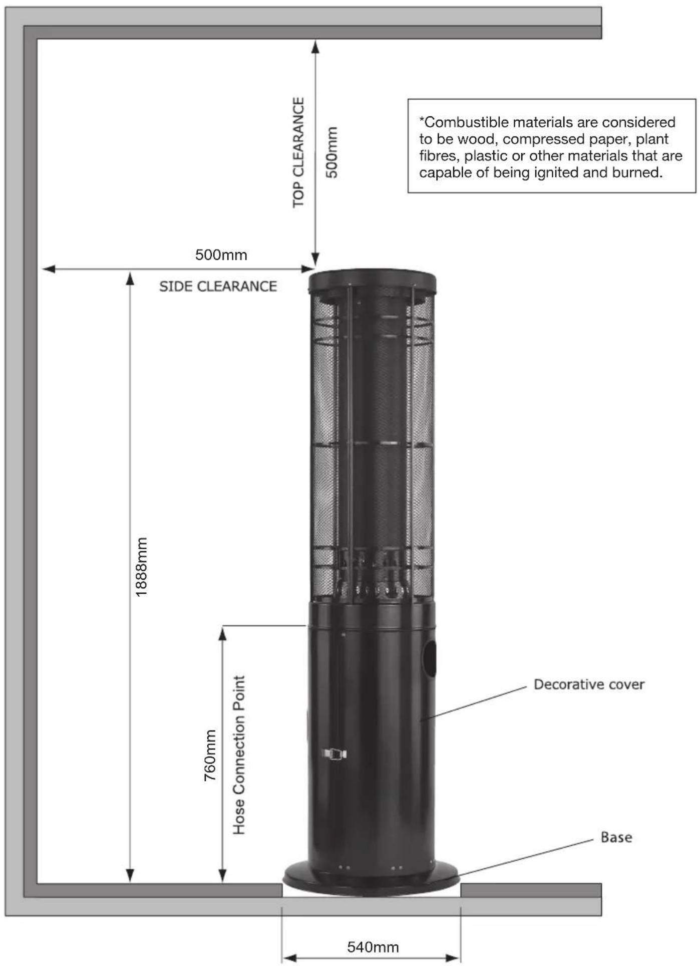
- Proper clearance from combustible materials must be maintained at all times. The minimum clearances are as follows:
Minimum Clearance from Combustibles
Side 500mm Rear 500mm
Ceiling 500mm Below 500mm
Combustible materials are considered to be wood, compressed paper, plant fibres, plastic, plexiglas or other materials capable of being ignited and burned. Such materials shall be considered combustible even though flame proofed, fire-retardant treated or plastered. Additional clearance may be required for glass, painted surfaces and other materials which may be damaged by radiant or convection heat.
- Heaters must be placed on a level and adequate footing and be readily accessible.
- The gas manifold supply pressure must be regulated at 2.75 kPa utilising an AGA approved regulator (supplied with heater).
- The appliance must be inspected before each use, and at least annually by a qualified service person.
a. The appliance area must be kept clear and free of combustible materials, gasoline and other flammable vapours and liquids.
b. Gas orifices and burner must be kept clear of dirt and cobwebs. Flow of and ventilation air through the perforated portions of the heater must not be obstructed. Cleaning with a soft brush before use and at least every six months is recommended.
c. All gas connections should be checked for leaks utilising a soap solution. NEVER use a flame for this purpose.
UTDOOR USE ONLY
d. The flame pattern at the emitter grid should be visually checked whenever heater is operated. If flames extend beyond surface of the emitter grid or black spot is accumulating on the emitter grid or reflector, the heater should be turned off immediately. The heater should not be operated again until the unit is serviced and or repaired.
e. Any cleaning agent used on the heater should be of a non-combustible and non-corrosive nature.
f. The stainless steel emitter grid normally does not require cleaning and should NEVER be painted.
-
The hose must be protected from contact with hot or sharp surfaces both during use and while in storage. The hose assembly should be visually inspected prior to each use of the heater. If excessive abrasion or wear is evident, or the hose is cut, it must be replaced prior to operating the heater. The replacement hose assembly may be obtained from the manufacturer.
-
DO NOT use any pressure regulator or hose assembly other than those supplied with the appliance. Replacement pressure regulator and hose assembly must be those specified. Replacement parts may be obtained from the manufacturer or your local sales representative.
-
Installation and use of this heater must conform with local codes or, in the absence of local codes, with the Standards of Storage and Handling of Liquefied Petroleum Gases.
-
This heater is designed to operate with a standard 9Kg propane cylinder with Approved Cylinder Connection.
-
The valve outlet must be maintained in good condition. When the cylinder is not in use, be sure to cover it with a dust cap. A leak test should be performed with soapy water whenever connecting a new cylinder. NEVER use a match to test for leaks.
-
The gas cylinder must be turned off whenever the heater is not in use. When the heater is to be stored indoors, the propane cylinder and the heater must be disconnected and the cylinder stored in accordance with the Standard for Storage and Handling of Liquefied Gases.
-
The heater has been designed with several safety features which include a tip over switch.
Any modification to the heater not described in the installation instructions may compromise the safety of this appliance. Special concern is as follows:
(1) DO NOT shorten post length;
(2) DO NOT bypass thermocouple safety;
(2) DO NOT operate heater without the reflector; Clothing or other flammable materials should not be hung from the heater, or placed on or near the heater. The area above the burner may be extremely hot. Direct contact with these metal surfaces should be avoided in order to prevent burns or clothing ignition.
POL CYLINDER CONNECTION DEVICE

Screw the coupling nut of regulator into the cylinder valve outlet.
| Type of Gas Propane | |
| Consumption 35 MJ/h | |
| Operating Pressure 2.75 kPa | |
| Injector Size 1.9 mm | |
Heater specifications can be found on the data label.
COLUMN HEATER ASSEMBLY
Tools Required
Phillips head screwdriver
2 adjustable spanners
STEP 1
Secure the base to the cylinder house body with five M6 x 15mm long screws, washers and nuts.
STEP 2
Secure the burner head lower to the cylinder house body with four M5 x 10mm long screws, washers and nuts. Attach the burner head upper using four M4 x 6mm long screws.
STEP 3
Locate the guards into the burner head support ensuring the pilot lighting hole is aligned with the hole in the burner tube and attach together using ten M4 screws 6mm long.
STEP 4
Position the guard cap over the guards and secure using six M4 screws 6mm long and to the burner head upper using an M8 x 20mm long screw.
STEP 5
Securely attach the hose to the burner head and the regulator to a gas cylinder, check the connections for leaks using a soap solution.
STEP 6
Sit the cylinder house door into the hinge, close and lock.

COLUMN HEATER - FOR OUTDOOR USE ONLY
Minimum Clearance from Combustible Surfaces*:
TEST FIRING HEATER
Test fire heater, following the lighting instructions. Leak test all gas connections with soapy water. Soap bubbles indicate gas leakage. DO NOT use a match to test for gas leaks.
TROUBLE SHOOTING
| Problem Possible Causes | |
| Pilot won’t light | Air in gas line |
| Low gas pressure | |
| Gas line turned ‘OFF’ | |
| Blockage in gas line | |
| Ignitor did not spark | |
| Pilot won’t stay lit | Suspect thermocouple |
| Corrosion of thermocouple contact | |
| Suspect valve | |
| Wind exceeding 16 kph | |
| Main burner will not light | No gas |
| Low gas pressure | |
| Blockage in orifice | |
| Manual valve not in ‘LIGHT’ position |
Note: If the appliance cannot be adjusted to perform correctly it should not be used until serviced or repaired.
LIGHTING INSTRUCTIONS
- Ensure that the control knob is off. Slowly open the gas cylinder valve.
- Press and turn the control knob to 'LIGHT' position, the rotary piezo will make a clicking sound.
- Check for pilot flame through pilot lighting hole. If pilot does not light turn control knob to 'OFF' position and try again from the start. Several attempts may be necessary.
- With the pilot alight keep control knob depressed for 15 seconds then turn the control knob to 'LOW'.
- For maximum heat turn control knob to 'HIGH'.
- To turn heater off, turn control knob to 'OFF'.
Note: Allow one minute to purge air through to pilot after connection to a new cylinder.


White smoke may appear around the emitter grid during the first minute of initial firing.
Improper installation, adjustment, alteration, service or maintenance can cause injury or property damage. Any modifications or adjustments made to product without prior authority from the manufacturer will void any warranty claims. Read the installation, operating and maintenance instructions thoroughly before installing or servicing this equipment.
SAFE APPLIANCE LOCATIONS
This appliance shall only be used in an above ground open-air situation with natural ventilation, without stagnant areas, where gas leakage and products of combustion are rapidly dispersed by wind and natural convection.
Any enclosure in which the appliance is used shall comply with one of the following:
An enclosure with walls on all sides, but at least one permanent opening at ground level and no overhead cover (see Example 1).
Within a partial enclosure that includes an overhead cover and no more than two walls (see Example 2 & 3).
Within a partial enclosure that includes an overhead cover and more than two walls, the following will apply:
at least 25% of the total wall area is completely open, and
at least 30% of the remaining wall area is open and unrestricted (see Example 4 & 5).
In the case of balconies, at least 20% of the total wall area shall be and remain open and unrestricted.
The following figures are diagrammatical representations of outdoor areas. Rectangular areas have been used in these figures - the same principles apply to any other shaped area.

natural_image
Isometric line drawing of a 3D rectangular box with a cutout and an adjacent empty rectangle (no text or symbols)Outdoor Area - Example 1
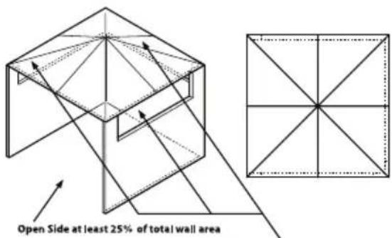
30% or more in total of the remaining wall area is open and unrestricted
Outdoor Area - Example 4

natural_image
Two geometric diagrams: a triangular prism with internal lines and a square divided into four quadrants by diagonals (no text or symbols)Outdoor Area - Example 2

30% or more in total of the remaining wall area is open and unrestricted
Outdoor Area - Example 5

Outdoor Area - Example 3
For any queries or assistance call

Customer Service
(Australia Only)
1300 174 876
Hours of operation:
Monday to Friday 8.30am - 5.30pm EST
Do not return to place of purchase.
Keep your purchase receipt, this will be required to make any claims under the 12 month warranty.
- Model No. CH205MBODS
- FOR YOUR SAFETY
- FOR OUTDOOR USE ONLY
- PROPANE GAS
- WARNING
- INSTALLATION, OPERATION & MAINTENANCE INSTRUCTIONS
- IMPORTANT SAFETY RULES
- Minimum Clearance from Combustibles
- UTDOOR USE ONLY
- COLUMN HEATER ASSEMBLY
- Tools Required
- STEP 1
- STEP 2
- STEP 3
- STEP 4
- STEP 5
- STEP 6
- COLUMN HEATER - FOR OUTDOOR USE ONLY
- TEST FIRING HEATER
- LIGHTING INSTRUCTIONS
- SAFE APPLIANCE LOCATIONS
- For any queries or assistance call
- Customer Service
- 174 876
- Do not return to place of purchase.
Brand : Gasmate
Model : Column Outdoor CH205MB
Category : Heating