
V-LCD17H - Screen MARSHALL - Free user manual and instructions
Find the device manual for free V-LCD17H MARSHALL in PDF.


| Product Type | LCD Monitor |
| Brand | Marshall |
| Model | V-LCD17H |
| Screen Size | 17 inches |
| Resolution | 1920 x 1080 pixels (Full HD) |
| Aspect Ratio | 16:9 |
| Brightness | 300 cd/m² |
| Contrast Ratio | 1000:1 |
| Viewing Angle | 178° horizontal / 178° vertical |
| Signal Inputs | 3G-SDI (x2), HDMI, Composite |
| Power Supply | AC 100-240V, 50/60Hz |
| Power Consumption | 30W (typical) |
| Weight | 5.2 kg (11.5 lbs) |
| Dimensions (W x H x D) | 402 x 332 x 100 mm (15.8 x 13.1 x 3.9 in) |
| Features | Wiring, image controls, waveform monitor, vector scope, focus assist, false color, pixel-to-pixel mapping |
| Cleaning | Use a soft, dry cloth; do not use solvents |
| Safety | Operate in dry environment, avoid liquid exposure |
| Spare Parts & Repairability | Contact Marshall authorized service centers for replacement parts |
| General Information | Professional broadcast monitor for field or studio use |
Frequently Asked Questions - V-LCD17H MARSHALL
User questions about V-LCD17H MARSHALL
0 question about this device. Answer the ones you know or ask your own.
Ask a new question about this device
Download the instructions for your Screen in PDF format for free! Find your manual V-LCD17H - MARSHALL and take your electronic device back in hand. On this page are published all the documents necessary for the use of your device. V-LCD17H by MARSHALL.
USER MANUAL V-LCD17H MARSHALL
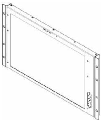
Rack Mountable High Definition LCD Monitor
natural_image
Technical line drawing of a rectangular frame with mounting flanges and a central blank space (no text or symbols)Operating Instructions
Edition 1 Revision 5P
大
1910 East Maple Ave. FL Canada, CA 02245
Tel: (800) 800-6608 / (310) 353-0605 • Fax: 310-353-0688
www.LCDRacks.com • sales@icdracks.com
This page intentionally left blank
Maintenance
■ Screen Cleaning
Periodically clean the screen surface using ammonia-free cleaning wipes (Marshall Part No. V-HWP-K). A clean micro-fiber cloth can also be used using only non-abrasive and ammonia-free cleaning agents. Do not use paper towels. Paper towel fibers are coarse and may scratch the surface of the polycarbonate faceplate or leave streaks on the surface. Antistatic and fingerprint resistant cleaning agents are recommended. Do not apply excessive pressure to the screen to avoid damaging the LCD.
■ Faceplate Dusting
Dust the unit with a soft, damp cloth or chamois. Dry or abrasive cloths may cause electrostatic charge on the surface, attracting dust particles. Neutralize static electricity effects by using the recommended cleaning and polishing practice.
Warranty
Marshall Electronics warranties to the first consumer that this V-LCD17H LCD monitor will, under normal use, be free from defects in workmanship and materials, when received in its original container, for a period of one year from the purchase date. This warranty is extended to the first consumer only, and proof of purchase is necessary to honor the warranty. If there is no proof of purchase provided with a warranty claim, Marshall Electronics reserves the right not to honor the warranty set forth above. Therefore, labor and parts may be charged to the consumer. This warranty does not apply to the product exterior or cosmetics. Misuse, abnormal handling, alterations or modifications in design or construction void this warranty. It is considered normal for a minimal amount of pixels, not to exceed three, to fall on the periphery of the display active viewing area. Marshall Electronics reserves the option to refuse service for display pixel failure if deemed unobtrusive to effective use of the monitor by our technicians. No sales personnel of the seller or any other person is authorized to make any warranties other than those described above, or to extend the duration of any warranties on behalf of Marshall Electronics, beyond the time period described above. Due to constant effort to improve products and product features, specifications may change without notice.
This page intentionally left blank
Table of Contents
Installation and Initial Setup 5
Top and Front Panel Features 7
Rear Panel Features 8
Input Module Installation----9
MAIN MENU AND NAVIGATION 10
This page intentionally left blank
This page intentionally left blank
Installation and Initial Setup
■ Unpacking
Carefully unpack the V-LCD17H monitor and verify that the following items are included:
• V-LCD17H Monitor
• V-PS12-5V-1 Power Supply
- Operating Instructions
Inspect the unit for any physical damage that may have occurred during shipping. Should there be any damage, immediately contact Marshall Electronics at (800) 800-6608. If you are not located within the continental United States, call +1 (310) 333-0606.
■ Installation
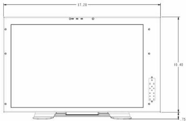
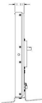
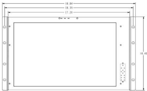
The V-LCD17H can be mounted in any standard EIA 19" equipment rack. The attached rack ears can be angled to provide the user control over the viewing angle. Adequate ventilation is required when installed to prevent possible damage to the monitor's internal components. Please see the Dimensions section for more information.
A VESA standard 75mm hole pattern also allows custom mounting installations. Alternately, the V-LCD17H can be used in a desktop configuration with optional stand. Please contact Marshall Electronics for more information.
■ Connections, Power-On and Initial Setup
Plug the power supply into an AC power source (100-240 V @ 50/60 Hz). Attach the Power connector to the back of the monitor. Connect the required cables for video signal input and output. (Power must be applied to the V-LCD17H for the active loop though output to be activated.) The monitor defaults to 'ON' when power is supplied. Video will automatically be detected and displayed on the screen.
This page intentionally left blank
natural_image
Technical line drawing of a vertical mechanical or electrical component with mounting holes and a side-mounted bracket (no text or symbols)Dimensions
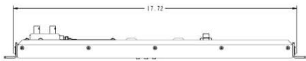
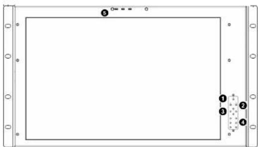
Top and Front Panel Features
natural_image
Pure geometric diagram with a rectangle and labeled regions, no text or symbols presentPower Button
Use the power button to toggle between ON and STANDBY modes. In both the STANDBY and the ON state, the LED on the button will illuminate bright green. This indicates that MAIN power is applied to the unit.
⑤ LED Tally
Three LED tally lights (yellow, red, green) are available above the screen.
② User-Definable Function Buttons
Four user-definable function buttons can be used for direct access to various settings. Functions are assigned using the on-screen menu.
Menu Navigation Buttons
Use the Menu, ▲, ▼, and Select buttons to display and navigate the on-screen menu (See Main Menu and Navigation).
4 Image Adjustment Knobs
Use the image adjustment knobs to adjust color brightness, color-saturation, tint, and contrast of the image. The status of each image adjustment parameter is shown on the bottom left of the screen, with values ranging from 0 to 100. Default value is 50.
Rear Panel Features
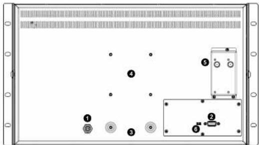
Power Input
Connect 12VDC to the 4-pin XLR power input connector. Power should only be supplied from the included power supply. IMPORTANT: If using a power source other than the included power supply, damage may result. Please use the pin out diagram in the Specifications section.
② Tally Input Connector
The LED tally can be activated via the HD-15 connector by connecting the corresponding pin to ground. A variety of external devices can be used to perform the contact closure. No additional power should be supplied to the HD-15 port.
3 Desktop Mounting Holes
These holes are used when attaching the monitor to the optional desktop stand.
4 VESA 75mm Hole Pattern
VESA-standard 75 mm hole-patterns is provided to accommodate a variety of custom mounting options. See Dimensions for further details.
Module Slot 1
The V-MD monitor comes with Module Slots for Marshall Electronics' line of future proof Input Modules. Please contact Marshall Electronics for a list of compatible Input Modules. See the Input Module Installation instructions for details on Module Installation.
PROG Port
The PROG port is a Service / Upgrade port only. Please contact Marshall Electronics for more information.
Specifications
■ PANEL
| Screen Size 17" Diagonal | |
| Display Area (h x v) | 367.20 x 229.50 mm |
| Pixels 1440 x RGB x 900 | |
| Viewing Angle | (h x v) 140° x 130° |
| Brightness 250 cd/m2 | |
| Contrast Ratio 600:1 | |
| Pixel Pitch (h x v) | 0.255 x 0.255 mm |
■ CONNECTORS
51 (Module 5lot)
For Marshall I/O Modules Only Cold-Swap – remove power from unit before Inserting or removing Modules.
Power Input
2-Pin Twist Lock Connector
Tally Hardware Interface
HD-15 Female
CN-1 - Programming Port\*
Factory / Upgrade Use Only
■ TALLY Hardware Interface (HD-15)
HD-15 Female
Activation requires contact closure of pin to ground on the HD-15 connector.

ELECTRICAL
Power Consumption 3.5A @ 12VDC (42 W) Voltage Requirement 12 VDC
12VDC
3.5A
⊕—●—-
MECHANICAL
Weight (with rack cars): 8.8 lbs
Operating Temperature 32°F to 104°F (0°C to 40°C) Storage Temperature -4°F to 120°F (-20°C to 50°C)
See Dimensions section for exact specifications.
SYSTEM INFORMATION SUBMENU
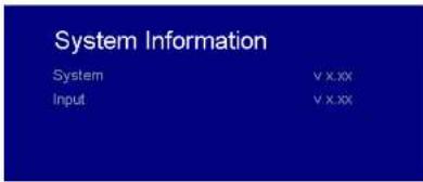
■ System
This shows the System firmware version of your monitor.
■ Input (Slot 1)
This shows your module type and the firmware version of your module. If no module is present, the word EMPTY will appear in parentheses.
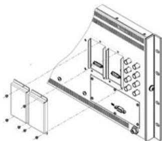
Input Module Installation
1. Remove Power From Unit
■ Modules are cold-swappable only. Damage will occur if modules are inserted or removed while unit is
2. Remove Blank Module Cover
- Using Philips screwdriver, remove the 4-40x1/8" screws. There are a total of three screws, save them for later USC.
■ Remove blank cover
3. Insert Optional Module
■ Decide which slot you intend to install module (Slot 1 or Slot 2)
■ Carefully align the module with the chosen slot. The raised rails will fit inside the module
- Align the Module so that the three [3] mounting holes all line up with the threaded holes of the slot.
■ The connectors on both the module and the main-board slot should now be in alignment
- Carefully PRESS the module into the slot. Module will seat flush with the rear of the unit.
■ Replace the three (3) screws removed in Step 2.
*NOTE Use ONLY screws provided. Any screw longer than those provided will damage the main unit.
natural_image
Technical line drawing of a mechanical assembly with no visible text or symbolsMAIN MENU AND NAVIGATION
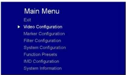
Access the main menu by pushing and holding the MENU button on the front panel of the monitor.
- Step through menu items using the ▲ and ▼ buttons.
- Choose a submenu or select a menu item by pressing SELECT.
- Return to the previous menu by pressing MENU.
- Exit the main menu by pressing MENU. The menu will automatically time out after 15 seconds.
Use this setting to choose one of three color temperature presets.
• D55 [5500K]
IMD CONFIGURATION
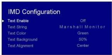
■ Text Enable
Use the Text Enable function to turn the MD Text feature ON. This will cause the Text String to appear on the lower portion of the screen.
■ Text String
Use this field to enter your own 15 character string on the screen.
■ Text Color
Use this field to change the color of the text in the Text String field.
■ Text Background
Use this field to change the opacity of the background behind the text in the Text String field. A value of 0% will cause the background to appear black. A value of 100% will make the background invisible.
■ Text Alignment
Use this field to change the alignment of the text string mentioned above.
Use this feature to choose between controlling the Contrast of the image or the intensity of the panel's Backlight with the CONTRAST button on your monitor. Note: While the Contrast control moves up and down at intervals of 1, the Backlight control will move up and down at intervals of 2, from 0-100.
■ Load Setup
Select this menu item to reset all adjustments and menu settings to the factory default configuration or to one of the user configured presets.
■ Save Setup
Select this menu item to save a current setup into one of 6 available user presets.
■ Power On Preset
Select this menu item to reset all adjustments and menu settings to the factory default configuration whenever the unit is powered down.
FUNCTION PRESETS SUBMENU
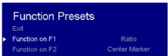
■ Function Presets
Allows user to assign menu items to the front panel function buttons: F1, F2. The following options are available for each button:
Ratio
- Check Field
- Mosquito Filter
- False Colors
- Freeze Input
- Aspect Markers
- Center Marker
- Marker Enable
- Pixel-to-Pixel
• D65 (6500K)
• 930DK
- USER (Adjustable Color Bias and Gain)
- Linear (No processing is applied to the panel)
Use this setting to enable monochrome mode. Only the luminance of the image will be displayed as a grayscale picture.
■ RGB Bias and Gain
Select this submenu to fine-tune the monitor's color balance (R, G, B). This should only be done by someone experienced with video engineering, as this will alter the overall color shading of the screen. The purpose is to allow color matching to other types of monitors and/or displays. Note: The Color Temperature preset will automatically switch to USER when Color Bias settings are adjusted. It is normal for color bias adjustments to be very subtle.
When selecting the RGB Bias and Gain submenu, gain adjustment indicators will appear at the top of the screen, and bias adjustment indicators will appear at the bottom of the screen:
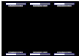
RGB Bias and Gain
Use the ▲ and ▼ buttons to select each individual bias or gain control. Press SELECT to begin adjusting the control. Use the ▲ and ▼ buttons to increase or decrease the value.
Alternatively, the image adjustment buttons (Brightness, Color, Tint, Contrast) can be used to easily adjust the bias and gain settings as shown below. The buttons affect whichever row of controls (gain or bias) is currently selected.
■ Check Field
Use the check field modes for monitor calibration or to analyze individual color components of an image. In Monochrome mode, all color is disabled and only a grayscale image is shown. In Blue, Green, and Red check field modes, only the selected color will be shown.
Use the following procedure when calibrating the monitor to SMPTE color bars with the following procedure:
- Allow the monitor to warm up for at least 5-10 minutes.
- Display SMPTE split-field color bars on the monitor using an external source.
-
Enable Monochrome mode.
-
Locate the pluge pattern (super black, black, and gray bars) at the lower-right corner of the screen. Adjust the Brightness button until there is no visible difference between the super black and black bars, but the gray bar is still visible.
-
Adjust the Contrast button until an even grayscale appears along the top bars.
- Disable Monochrome mode.
- Enable Blue Check Field mode and adjust the Color button so that the outermost bars (white and blue) appear to match in brightness.
- Composite NTSC only: Adjust the Tint button until the third bar from the left (cyan) and the third bar from the right (magenta) appear to match in brightness.
- Disable Blue Check Field mode.
■ Ratio Settings
Use to switch between Full Screen, 4:3 and 16:9 aspect ratios.
• In Full Screen mode, images are scaled to fill the entire screen.
- In 4:3 mode, images are scaled to fill the center 4:3 portion of the screen. With a 16:9 source, images will be centered with a black letter-box added on the left and right sides.
• In 16:9 mode, images are scaled to a 16:9 portion of the screen, with a black letter-box added top and bottom.
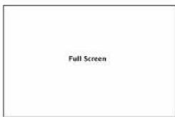
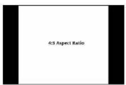
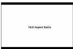
Note: The aspect ratio setting is ignored when Pixel-to-Pixel mode is enabled.
■ Pixel-to-Pixel
Use this setting to enable Pixel-to-Pixel mode.
This Pixel-to-Pixel mode bypasses the monitor's internal scaling function and displays incoming images in their native resolution and aspect ratio, with a one-to-one mapping:
■ Mosquito Filter
Use this setting to filter out "Mosquito Noise" — an artifact that appears as specs around edges of objects. This artifact is the result of video that has been compressed at some point. Video sources from DVD-Players, PDA's, Digital Cable Boxes, Camcorders, etc. often have this artifact.
Use the Color-Configuration submenu to adjust the color temperature of the display.
Color Configuration Submenu
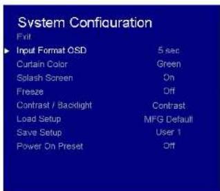
■ Input Format OSD
Use this option to enable on-screen display of input/format status in the upper-left corner of the screen.
■ Curtain Color
Use this option to change the curtain color on the monitor. This curtain color is what you see when there is no signal input to the monitor.
■ Splash Screen
Use this option to enable or disable the Marshall Electronics Inc. splash screen seen when the monitor is first powered on,
■ Freeze
Use the Freeze function to "freeze" the current image on the screen. Select this menu item again (Unfreeze) to return to the real-time video input.
■ Contrast / Backlight
FILTER CONFIGURATION SUBMENU
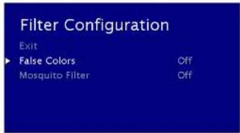
False Colors
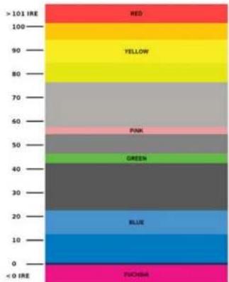
This monitor has a false color filter to aid in the setting of camera exposure. As the camera iris is adjusted, elements of the image will change color based on the luminance or brightness values. This enables proper exposure to be achieved without the use of costly, complicated external equipment. To best utilize this feature, you must understand the color chart below and have a basic understanding of camera exposure. Normally, when shooting subjects like people, it is common practice to set exposure of faces to the equivalent of approximately 56 IRE. The false color filter will show this area as the color PINK on the monitor. Therefore, as you increase exposure (open the IRE), your subject will change color as indicated on the chart: PINK, then GREY, then a few shades of YELLOW. Over-exposed subjects (above 101 IRE) on the monitor will be shown as RED. In addition, underexposed subjects will show as DEEP-BLUE to DARK-BLUE, with clipped-blacks indicated with a FUCHSIA-like color. Lastly, the color GREEN is used to indicate elements of the image that are approximately 45 IRE. This represents a 'neutral' or 'mid-level' exposure commonly used for objects (not people).
- For incoming formats smaller than the native resolution of the LCD panel, the image will be displayed in the center of the screen using only the necessary LCD pixels. For example, NTSC images will occupy exactly 720 x 480 pixels. The surrounding pixels will be black.
Note: Pixel-to-Pixel mode disables aspect ratio control and H/V Delay.
MARKER CONFIGURATION SUBMENU
Use the Video Configuration submenu to select various video settings such as monochrome mode or blue-only mode.
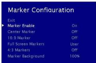
Marker Configuration Submenu
Marker Enable
Use this setting to enable or disable all on-screen markers. This setting affects the center marker, full screen markers, 16:9 markers and 4:3 markers.
■ Center Marker
Use this setting to display a center marker on the screen.
■ 16:9 Markers
Use these settings to superimpose one of 12 markers on the screen when in 16:9 mode.
• 4:3
13:9
• 14:9
• 1.85.1
• 2.35:1
- 95% Safe
• 93% Safe
• 90%5
• 88% Safe
• 85% Safe
• 80% Safe
16:9 Marker Examples:
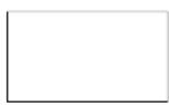
OFF (No Market)
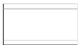
2.35:1 Aspect Ratio
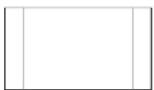
4.3 Aspect Ratio Marker
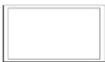
90% Safe Area
■ Full Screen Markers
Use these settings to superimpose one of 6 markers on the screen when in Full Screen mode.
95% Safe
- 93% Safe
90%Safe
■ 88% Safe
85% Safe
■ 80% Safe
■ 4:3 Markers
Use this setting to superimpose one of 5 markers on the screen when in 4:3 mode.
- 95% Safe Area
• 93% Safe Area
• 90% Safe Area
• 88% Safe Area - 85% Safe Area
• 80% Safe Area
4:3 Marker Examples:
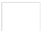
OFF (No Marker)
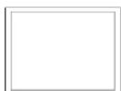
90% Safe Area
Marker Background
Use this setting to choose how selected markers are displayed on the screen.
• 0% The marker is superimposed on the complete image.
• 25% Image area beyond the marker is shown at 25% intensity.
• 50% Image area beyond the marker is shown at 50% intensity.
• 75% Image area beyond the marker is shown at 75% intensity.
• 100% Image area beyond the marker is shown at 100% intensity (black).
Example (80% Marker in 4:3 Mode):
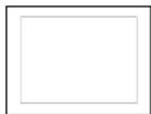
0% Background
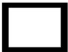
100% Background
- Maintenance
- ■ Screen Cleaning
- ■ Faceplate Dusting
- Warranty
- Table of Contents
- Installation and Initial Setup
- ■ Unpacking
- ■ Installation
- ■ Connections, Power-On and Initial Setup
- Power Button
- ⑤ LED Tally
- ② User-Definable Function Buttons
- Menu Navigation Buttons
- Image Adjustment Knobs
- Power Input
- ② Tally Input Connector
- Desktop Mounting Holes
- VESA 75mm Hole Pattern
- Module Slot 1
- PROG Port
- Specifications
- ■ PANEL
- ■ CONNECTORS
- (Module 5lot)
- Tally Hardware Interface
- CN-1 - Programming Port\*
- ■ TALLY Hardware Interface (HD-15)
- ELECTRICAL
- MECHANICAL
- SYSTEM INFORMATION SUBMENU
- ■ System
- ■ Input (Slot 1)
- Input Module Installation
- Remove Power From Unit
- Remove Blank Module Cover
- Insert Optional Module
- MAIN MENU AND NAVIGATION
- IMD CONFIGURATION
- ■ Load Setup
- ■ Save Setup
- ■ Power On Preset
- FUNCTION PRESETS SUBMENU
- ■ Function Presets
- • D65 (6500K)
- ■ RGB Bias and Gain
- ■ Check Field
- ■ Ratio Settings
- ■ Pixel-to-Pixel
- ■ Mosquito Filter
- ■ Input Format OSD
- ■ Curtain Color
- ■ Splash Screen
- ■ Freeze
- ■ Contrast / Backlight
- FILTER CONFIGURATION SUBMENU
- False Colors
- MARKER CONFIGURATION SUBMENU
- Marker Enable
- ■ Center Marker
- ■ 16:9 Markers
- ■ Full Screen Markers
- ■ 4:3 Markers
- Marker Background
Brand : MARSHALL
Model : V-LCD17H
Category : Screen