
V-R1041-IMD-3G - Screen MARSHALL - Free user manual and instructions
Find the device manual for free V-R1041-IMD-3G MARSHALL in PDF.


| Product Type | High Definition LCD Monitor with In-Monitor Display (IMD) |
| Model | V-R1041-IMD-3G |
| Screen Size | 10.4 inches diagonal |
| Display Resolution | 1042 x RGB x 768 pixels |
| Viewing Angle | 170° horizontal x 170° vertical |
| Brightness | 300 cd/m² |
| Contrast Ratio | 700:1 |
| Video Input | 1 x BNC (75 Ω) for 3G-SDI |
| Video Output | 1 x BNC (75 Ω) active loop-through |
| Headphone Output | 1/8" (3.5mm) female jack |
| Power Requirement | 12 VDC (included power supply with 100-240 VAC input) |
| Weight (with rack ears) | 1.75 lbs |
| Operating Temperature | 32°F to 104°F (0°C to 40°C) |
| Storage Temperature | -4°F to 120°F (-20°C to 50°C) |
| Compliance | RoHS |
| Cleaning Instructions | Use ammonia-free cleaning wipes (Marshall Part No. V-HWP-K) or a clean micro-fiber cloth with non-abrasive, ammonia-free agents. Do not use paper towels. |
| Warranty | 1 year from purchase date for the first consumer against defects in workmanship and materials |
| Mounting | Standard EIA 19" Half Rack space with adjustable rack ears |
| Serial Interface | RS-422/485 via RJ12 (2 ports) for remote control and looping |
| Tally Interface | HD-15 female for contact closure tally and GPI |
Frequently Asked Questions - V-R1041-IMD-3G MARSHALL
User questions about V-R1041-IMD-3G MARSHALL
0 question about this device. Answer the ones you know or ask your own.
Ask a new question about this device
Download the instructions for your Screen in PDF format for free! Find your manual V-R1041-IMD-3G - MARSHALL and take your electronic device back in hand. On this page are published all the documents necessary for the use of your device. V-R1041-IMD-3G by MARSHALL.
USER MANUAL V-R1041-IMD-3G MARSHALL
Periodically clean the screen surface using ammonia-free cleaning wipes (Marshall Part No. V-HWP-K). A clean micro-fiber cloth can also be used using only non-abrasive and ammonia-free cleaning agents. Do not use paper towels. Paper towel fibers are coarse and may scratch the surface of the polycarbonate faceplate or leave streaks on the surface. Antistatic and fingerprint resistant cleaning agents are recommended. Do not apply excessive pressure to the screen to avoid damaging the LCD.
■ Faceplate Dusting
Dust the unit with a soft, damp cloth or chamois. Dry or abrasive cloths may cause electrostatic charge on the surface, attracting dust particles. Neutralize static electricity effects by using the recommended cleaning and polishing practice.
Warranty
Marshall Electronics warranties to the first consumer that this V-R1041-IMD-3G LCD monitor will, under normal use, be free from defects in workmanship and materials, when received in its original container, for a period of one year from the purchase date. This warranty is extended to the first consumer only, and proof of purchase is necessary to honor the warranty. If there is no proof of purchase provided with a warranty claim, Marshall Electronics reserves the right not to honor the warranty set forth above. Therefore, labor and parts may be charged to the consumer. This warranty does not apply to the product exterior or cosmetics. Misuse, abnormal handling, alterations or modifications in design or construction void this warranty. It is considered normal for a minimal amount of pixels, not to exceed three, to fall on the periphery of the display active viewing area. Marshall Electronics reserves the option to refuse service for display pixel failure if deemed unobtrusive to effective use of the monitor by our technicians. No sales personnel of the seller or any other person is authorized to make any warranties other than those described above, or to extend the duration of any warranties on behalf of Marshall Electronics, beyond the time period described above. Due to constant effort to improve products and product features, specifications may change without notice.
★
1910 East Maple Ave.
Tel: (801) 900-6608 / (310) 333-0608 • Fax: 210-333-0688
www.LCDRacks.com • sales@lodracks.com

Model No. V-R1041-IMD-3G
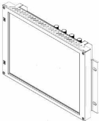
High Definition LCD Monitor with In-Monitor Display
natural_image
Technical line drawing of a rectangular electronic device with mounting brackets and a central panel (no text or symbols)Operating Instructions
Edition 3 Revision 1P
This page intentionally left blank
natural_image
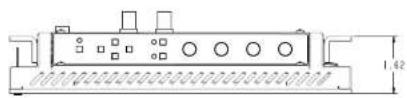
Technical line drawing of a mechanical component with mounting holes and a central hub (no text or symbols)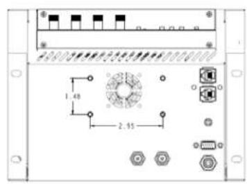
Dimensions
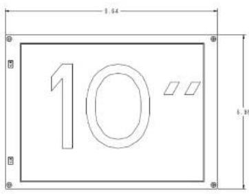
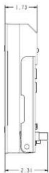
Table of Contents
Installation and Initial Setup 5
Top and Front Panel Features 6
Rear Panel Features 7
Compatible Input Formats----8
MAIN MENU AND NAVIGATION----9
Using the menu buttons....9 Using the Data Move Inch....0
Using the Rotomichu Khob 9 MARKER SETUO SUBMENI 20
MARKER SET OF SUBMENO....10 VIDEO CONFIGURATION SUBMENU 12
COLOR CONFIGURATION SUBMENU 15
This page intentionally left blank
Specifications
■ PANEL
Screen Size 10.4" Diagonal
Display Area (h x v) 210.43 x 157.82 mm
Pixels 1042 x RGB x 768
Viewing Angle(h x v) 170° x 170°
Brightness 300 cd/m2
Contrast Ratio 700:1
1 x BNC Female (75 Ω)
3G-SDI Video Output (Active Loop-Through)
1 x BNC Female (75 Ω)
Headphone Out
1/8" (3.5mm) Female Jack
Power Input
2-Pin Twist Lock
Tally Hardware Interface
HD-15 Female
RS-422/485 Interface
2 x RJ12 [Modular 6P6C]
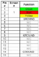
■ TALLY/GPI HARDWARE INTERFACE (HD-15)
Activation requires contact closure of pin to ground on the HD-15 connector:
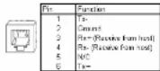
■ RS-422/485 SERIAL INTERFACE (RJ12)
Protocols: Image Video, TSL v4.0, MEI
ELECTRICAL
Voltage Requirement 12 VDC
MECHANICAL
Weight (with rack ears): 1.75 lbs
Operating Temperature 32°F to 104°F (0°C to 40°C)
Storage Temperature -4°F to 120°F (-20°C to
50°C
See Dimensions for exact specifications.
■ COMPLIANCE
RoHS Do not dispose. Return to Manufacturer or Authorized Recycle Facility
SERVICE SUBMENU
Overview
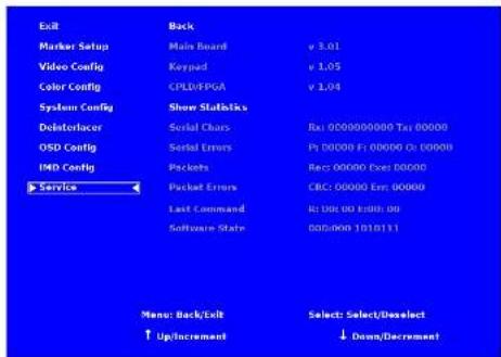
The Service submenu displays the firmware versions of the monitor. Additionally, the status of the serial interface, for troubleshooting or debugging purposes, can be shown on the screen by highlighting and selecting the Show Statistics text in the Service Submenu. Contact Marshall Electronics for further information.
IMD Configuration Submenu
The following information is displayed:
- Serial Characters Rx: Total number of characters received by the UART
Tx: Total number of characters transmitted by the UART - Serial Errors P: Number of parity errors
F: Number of framing errors
O: Number of FIFO overrun errors - Packets Rec: Number of packets received
Exe: Packets Executed - Packet Errors CRC: Number of packets that failed CRC check
Err: Number of other packet errors
• Last Command R: Last command received
E: Last command executed
• Software State State: 000:000 1010111 (correct value)
Installation and Initial Setup
■ Unpacking
Carefully unpack the V-R1041-IMD-3G monitor and verify that the following items are included:
• V-R1041-IMD-3G Monitor
• V-PS12-5V-1 DC Power Supply
- Operating Instructions
Inspect the unit for any physical damage that may have occurred during shipping. Should there be any damage, immediately contact Marshall Electronics at (800) 800-6608. If you are not located within the continental United States, call +1 (310) 333-0606.
■ Installation
The V-R1041-IMD-3G can be mounted in any standard EIA 19" Half Rack space. The attached rack cars can be angled to provide the user control over the viewing angle. Adequate ventilation is required when installed to prevent possible damage to the monitor's internal components. Please see the Dimensions section for more information.
■ Connections, Power-On and Initial Setup
Plug the DC Power Supply into an AC power source (100-240 V @ 50/60 Hz). Attach the Power connector to the back of the monitor. Connect the required cables for video signal input and output. (Power must be applied to the V-R1043-IMD-3G for the active loop though output to be activated.) The monitor defaults to 'ON' when power is supplied. Video will automatically be detected and displayed on the screen.
Top and Front Panel Features
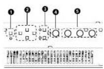
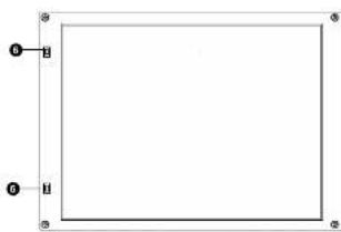
natural_image
Simple geometric diagram with a rectangle and two labeled corner points (no text or symbols)Power Button
Turn the monitor panel off or on by pressing the power button. In the ON state, the LED on the power button will illuminate green.
② Menu Navigation Buttons
Use the Menu, ↑, ↓, and Select buttons to display and navigate the on-screen menu. See MAIN MENU AND NAVIGATION for details on using the Menu.
3 User-Definable Function Buttons
Two user-definable function buttons can be used for direct access to various settings. Functions are assigned using the on-screen menu. See SYSTEM CONFIGURATION SUBMENU for Information on changing Functions.
4 RotoMenu™ Knob
The RotoMenu™ knob is alternate means of accessing and navigating the main menu, using only a single control. See the Using the RotoMenu knob section for details on using the RotoMenu. Also, turning the RotoMenu™ knob before pressing it adjusts the Headphone volume on monitors with an available Headphone Jack.
Image Adjustment Knobs
Use the image adjustment knobs to adjust color saturation, brightness and contrast of the image. The status of each image adjustment parameter is shown on the bottom left of the screen, with values ranging from 0 to 100. Pressing a knob once displays the current value. Pressing a knob twice resets the corresponding adjustment to the default setting. See VIDEO CONFIGURATION SUBMENU for information on Blue Only calibration.
LED Tally
Two LED tally lights (red, green) are available near each individual screen. Each tally light can be controlled from a variety of sources. See IMD CONFIGURATION SUBMENU for more details.
■ IMD Fixed Color
Use this setting to choose the color of the IMD Fixed String text (see below). Available colors are red, green, and yellow. This setting does not affect text color when using IMD text via the Image Video or TSL v4.0 protocols (text color is set via the protocols).
■ IMD Fixed String
Use this setting to display static IMD text on the screen. This setting is used to enter IMD text locally, when a serial protocol is not used for remote control. The IMD Fixed String is saved after power cycle. The IMD Fixed String will be overridden by serial protocol commands.
Press ENTER to edit the IMD Fixed String. Use the ↑ and ↓ buttons to move the cursor. Press ENTER with the cursor on the character to be changed and use the ↑ and ↓ buttons to scroll through character options. Press ENTER to choose a character.
■ Tally Source
The V-R1041-IMD-3G tally (OSD and LED) can be controlled in a variety of different ways. Use the Tally Source setting to choose how tally is controlled:
Standard
Use the Standard setting to control tally via contact closure on the HD-15 tally interface.
Image Video HW
Use the Image Video HW setting to control Image Video tally states via contact closure on the HD-15 tally interface. Contact closure of the Red pin corresponds to Image Video Tally 1, and the Green pin maps to Image Video Tally 2. Contact closure (ground) corresponds to a LOW state, and open circuit corresponds to a HIGH state. This mode requires the IMD Tally Mode parameter to be set. Consult Image Video documentation for further information.
Image Video 422
Use the Image Video 422 setting to control Image Video tally states via the Image Video serial protocol. LED and OSD tally will be disabled in this mode, as image video tally states are manifested in the text color and other parameters. This mode requires the IMD Tally Mode parameter to be set. Consult Image Video documentation for further information.
Standard + IV422
Use the Image Video 422 setting to control Image Video tally states via the Image Video serial protocol, while controlling LED and OSD tally using contact closure on the HD-15 tally interface. This mode requires the IMD Tally Mode parameter to be set. Consult Image Video documentation for further information.
TSL/MEI 422
Use the TSL/MEI 422 setting to control OSD and LED tally via the TSL or Marshall serial protocols.
■ IMD Tally Mode
Use this setting when using Image Video tally control. Choose one of the following settings, in conjunction with the Image Video controlling device. T1, T2, T1T2, T2T1, T1-, T2-, T1T2-, T2T1-. Consult Image Video documentation for further information.
■ IMD Protocol
Use the IMD Protocol menu option to choose the protocol with which the V-R1041-IMD-3G receives remote commands. Currently, four protocols are available. Contact Marshall Electronics for the latest protocol compatibility.
Image Video
Use the Image Video protocol setting when controlling the IMD from an Image Video tally controller (e.g. TSI-1000) or other controlling device which utilizes the Image Video protocol. The IMD #, IMD Name[S/N], and Baud Rate parameters must be set for each screen in conjunction with the controlling device.
TSL v4.0
Use the TSL v4.0 protocol setting when controlling the IMD from a TSL tally controller, or other controlling device which utilizes the TSL v4.0 protocol. The IMD # must be set for each screen in conjunction with the controlling device.
MEI
Use the MEI protocol setting when controlling the V-R1041-IMD-3G using the Marshall Network Controller box. This protocol allows remote control of all features on the V-R1041-IMD-3G, including marker setup, video configuration, system configuration, and image adjustments (brightness, contrast, etc.). The IMD #, IMD Group #, and Baud Rate parameters must be set in conjunction with the Network Controller Box.
MEI-Image Video
This protocol setting accepts Image Video commands via MEI protocol, for use when an Image Video controller is connected to the Marshall Network Controller box.
■ IMD ID #
The IMD ID # identifies each screen to the controlling device. When using the TSL protocol, the ID # of each screen should be manually set in conjunction with the controlling device. When using the Image Video protocol, the ID # may be set automatically by the controlling device, after each IMD is initially identified by IMD Name (see "IMD Name[S/N]" below). Available ID #s are 000-255. When using the Marshall protocol, available ID #s are 001-254.
■ IMD Group #
Each screen can be assigned an IMD Group # when using the Marshall protocol. Available Group #s are 01-254.
■ IMD Name (S/N)
Use this setting to assign a name to each screen when using the Image Video or Marshall-IV protocols. The IMD name is equivalent to the Image Video serial number and is used by the Image Video controlling device to identify each screen. The default IMD Name[S/N] is "M00000." It is recommended to maintain this naming scheme in order to avoid serial number conflicts with other Image Video devices on the same serial bus. Each name can be up to 16 ASCII characters.
Press ENTER to edit the IMD Name. Use the ↑ and ↓ buttons to move the cursor. Press ENTER with the cursor on the character to be changed and use the ↑ and ↓ buttons to scroll through character options. Press ENTER to choose a character.
■ IMD Baud Rate
Use this setting to choose the baud rate. The baud rate must be set in conjunction with the controlling device. Available baud rates are 300, 600, 1200, 2400, 4800, 9600, 19200, 38400, 57600, 115200. The TSL v4.0 protocol is fixed at 38400 bauds.
■ IMD Fixed Align
Use this setting to choose the horizontal alignment of the IMD text. IMD text can be justified on the left, center or right of the screen. This setting is overridden when using IMD text via the Image Video protocol (alignment is set via Image Video protocol).
Rear Panel Features
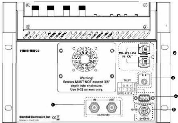
3G-SDI Input and Output
The V-R1041-IMD-3G has one HD-SDI input and one active loop-through output. See Compatible Input Formats for details on accepted formats.
2 RS-422/485 Serial Interface
The RS-422/485 ports are used to remotely control the IMD or all V-R1041-IMD-3G features, using a variety of industry standard protocols. (Note: Connector/pin-out may need to be adapted depending on protocol and controlling device used). Only one connection to either port is needed to control the monitor. The second port can be used to loop multiple monitors in the same bus. See IMD CONFIGURATION SUBMENU for further details.
3 Headphone Jack
The 1/8" jack on the back of the monitor takes two channels of embedded SDI audio and provides a Headphone audio signal. Volume can be adjusted via the RotoMenu knob or in the Audio Configuration submenu.
See the Audio Configuration section for instructions on how to select the two audio channels.
Tally / GPI Interface (HD-15)
LED tally, OSD tally and GPI can be activated via the HD-15 connector by connecting the corresponding pin to ground. A variety of external devices can be used to perform the contact closure. No additional power should be supplied to the HD-15 port. See the System Configuration section for details on configuring GPI.
5 Power Input
Connect the 12VDC input to the power input connector. Power can be supplied from the included power supply, or from a variety of DC sources supplying at least 5.0 Amps at 12 Volts.
Compatible Input Formats
SDI/HDSDI Inputs
525i/59.94,625i/50
720p/ 23.98, 24, 25, 29.97, 30, 50, 59.94, 60
1080p/23.98, 23.98sF, 24, 24sF, 25, 29.97, 30
10351/59.94,60
1080i/50,59.94,60
3G-SDI Inputs
3G - Level A and Level B
YCbCr, YCbCr+A, RGB, RGB+A
1080p/60,59.94,50
1080p/30, 29.97, 25, 24, 23.98, 30sF, 29.97sF, 25sF, 24sF, 23.98sF
1080i/60,59.94,50
■ Mute
The Mute function disables audio output from Headphone output on the IMD 3G monitor. This will NOT control the Line Out level of the monitor, only the Headphone output.
Volume
The Volume control determines the output level for the Headphone out on the IMD-3G monitor. This will NOT control the Line Out level of the monitor, only the Headphone output.
■ Audio Delay
The Audio Delay function applies a delay to the Audio Metering and audio output. Use the function to select a delay between 000 and 015 (in terms of fields, or frames if the signal is progressive).
■ Left Ch. Select
Use this setting to select which of the 16 possible channels you would like to play on the Left side of the stereo output.
■ Right Ch. Select
Use this setting to select which of the 16 possible channels you would like to play on the Right side of the stereo output.
IMD CONFIGURATION SUBMENU
Overview
The V-R1041-IMD-3G features an In-Monitor Display (IMD) with the ability to display on-screen text and tally in three colors. IMD text, color, and alignment can be assigned to each screen locally using menu options (see below). Alternately, IMD text and tally can be remotely controlled via the RS-422/485 serial interface using several industry-standard protocols, including TSL v4.0 and Image Video. Multiple V-R1041-IMD-3G monitors can be looped together and each addressed individually via the protocol. All menu features of the V-R1041-IMD-3G can also be controlled via the Marshall Network Controller box using MEI protocol. (Contact Marshall Electronics for additional information).
Use the IMD Configuration submenu to configure various IMD parameters as described below.
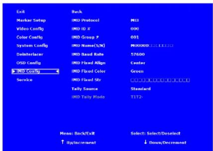
IMD Configuration Submenu
AUDIO CONFIGURATION SUBMENU
Use the Audio Configuration submenu to
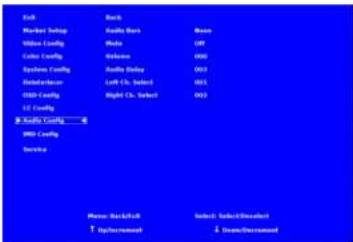
■ Audio Bars
The IMD-3G monitor series provides audio level indicators for SDI streams with embedded audio. Support for up to 16 channels (labeled as Groups 1, 2, 3 and 4) is provided.
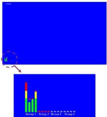
bar
| Group | Value | |---|---| | Group 1 | 20 | | Group 2 | 35 | | Group 3 | 40 | | Group 4 | 30 |Audio groups 1-4 shown on the screen
MAIN MENU AND NAVIGATION
Access and navigate the main menu using the 4 menu buttons or the RotaMenu™ knob:
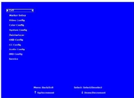
Main Menu
Using the menu buttons
- Press the MENU button to enter the main menu.
• Use the ↑ and ↓ buttons to scroll through the main menu or each submenu. - Press the SELECT button to enter a submenu or choose a setting.
• Press the MENU button to exit the main menu, or return to the main menu from a submenu.
Using the RotoMenu knob
- Press the RotoMenu™ knob to enter the main menu.
- Rotate the knob to scroll up or down in the main menu or each submenu.
- Press the RotoMenu ^TM knob to enter a submenu or choose a setting.
Before pressing the RotoMenu™ knob, turn it to adjust the Headphone volume level.
The menu automatically times out after 15 seconds of being idle.
MARKER SETUP SUBMENU
Use the Marker Setup submenu to select various types of markers and settings in 4:3, 16:9, or Full Screen mode.
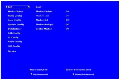
Marker Setup Submenu
Marker Enable
The Marker Enable setting turns 16:9 or 4:3 screen markers On or Off. By default, this setting is On. If you turn the setting OFF, the markers are automatically turned ON the next time you initiate a Screen Marker through a Function Button or through the Marker submenu.
■ 16:9 Markers
Use this setting to superimpose one of 10 markers on the screen when in 16:9 or Full Screen mode. This setting is disabled when the aspect ratio is set to 4:3, or when Pixel-to-Pixel mode is enabled. Note that in Full Screen mode, markers are vertically stretched along with the picture to fit the 16:10 screen.
- Off (No Marker)
- 95% Safe Area
- 93% Safe Area
- 90% Safe Area
• 88% Safe Area
- 60% Safe Area
• 1.85:1 Aspect Ratio
• 2.35:1 Aspect Ratio
- 4.5 Aspect Ratio
• 24.5 Aspect Ratio
16:9 Marker Examples:
OFF (No Marker)
90% Sale Area
CC CONFIGURATION SUBMENU
Use the CC Configuration submenu to select the type of captioning stream you would like to decode.
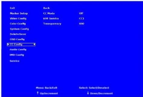
IMD Configuration Submenu
CC Mode
The IMD-3G monitor series provides support for two types of Closed Captioning Modes: 608 and 708 (608 Comp.). Use this section to choose which type of stream you would like to decode.
■ 608 Service
The FIA 608 caption protocol defines four channels of caption information and four channels of text information. The monitor can only display one of these channels at a time. With the 608 Service selections, you can select which of the four streams to render on the screen.
■ Transparency
The transparency function affects the T1-T4 Closed Caption services. The transparency can be adjusted from 000-100, with 100 allowing full transparency.
When the Tally Source is set to TSL/MEI 422, OSD Tally can be set to Off or IMD:
- Off On-screen tally is disabled
- IMD Red, yellow, and green tally is displayed according to the protocol commands. Green, red, and yellow colors are shown individually on either the bottom left or right of the screen.
■ LED Tally
Use this setting to enable or disable the LED Tally. When enabled, the red and green LEDs above the display will respond to tally commands, according to the Tally Source setting.
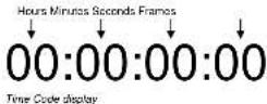
■ Anc. Time Code
Use this setting to enable time code display on the screen. Time code is de-embedded from the vertical ancillary data (VANC) within the SDI signal. Two types of time code can be selected to display on the screen: LTC (linear time code) or VITC (vertical interval time code).
The position of the time code display varies based on the aspect ratio setting and presence of IMD text.
■ Audio Monitor
Use the Audio Monitor menu option to enable or disable the audio presence indicator icon. When enabled, this icon indicates whether embedded audio is present in the SDI video input. A red circle and cross will flash on the icon if no embedded audio is present.

Embedded Audio Present

No Embedded Audio
■ 4:3 Markers
Use this setting to superimpose one of 5 markers on the screen when in 4:3 mode. This setting is disabled when the aspect ratio is set to 16:9 or Full Screen, and when Pixel-to-Pixel mode is enabled.
- Off [No Marker]
- 95% Sale Area
- 93% Safe Area
- 90% Safe Area
- 88% Safe Area
- 80% Safe Area
4.3 Marker Examples:
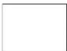
OFF (No Marker)
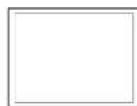
90% Safe Area
Marker Background
Use this setting to choose how selected markers are displayed on the screen:
• Off The marker is superimposed on the complete image.
- 50% Gray Screen area beyond the marker is shown at 50% intensity.
- Black Screen area beyond the marker is shown as black.
Example (80% Marker in 4:3 Mode):
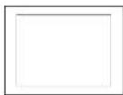
Background OFF
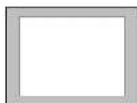
50% Grey Background
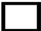
Black Background
■ Center Marker
Use this setting to display a center marker on the screen.
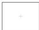
Center Marker
Use the Video Configuration submenu to select various video settings such as monochrome mode or blue-only mode.
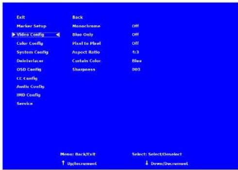
Video Configuration Submenu
■ Monochrome Mode
Use this setting to enable monochrome mode. Only the luminance of the image will be displayed as a grayscale picture.
■ Blue-Only Mode
Use this setting to enable Blue-Only mode. This mode displays only the blue color component of the image, switching off the red and green components. Use this mode when calibrating the monitor to SMPTE color bars with the following procedure:
- Allow the monitor to warm up for at least 5-10 minutes.
- Display SMPTE split-field color bars on the monitor using an external source.
- Enable Monochrome mode.
- Locate the pluge pattern (super black, black, and gray bars) at the lower-right corner of the screen. Adjust the Brightness knob until there is no visible difference between the super black and black bars, but the gray bar is still visible.
- Adjust the Contrast knob until an even grayscale appears along the top bars.
- Disable Monochrome mode.
- Enable Blue-Only mode and adjust the Color knob so that the outermost bars (white and blue) appear to match in brightness.
■ OSD Tally
Use this setting to choose how tally is displayed on the screen. The available OSD Tally options depend on the Tally Source selected in the IMD Configuration submenu (see page 22).
When the Tally Source is set to Standard (contact closure), OSD Tally can be set to Off, RGY, RG, or GR:
- Off On-screen tally is disabled
- RGY Red, yellow, or green tally signals are indicated at both the bottom left and bottom right corners of the screen. Two or three colors are shown simultaneously by subdividing each tally indicator
• RG Red tally is shown at the bottom left of the screen, and green is shown at the bottom right.
- GR Green tally is shown at the bottom left of the screen, and red is shown at the bottom right.
The following diagrams show RGY, RG, and GR OSD Tally modes:
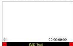
RGY mode: single color activated
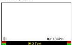
RGY mode: two colors activated
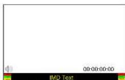
PGY mode: three colors activated
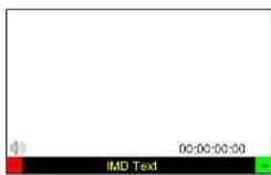
AG Mode: both colors activated
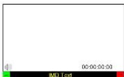
GR Mode, both colors activated
■ IMD State
Use this setting to turn the IMD text display on or off. This setting affects both fixed string IMD text and remote IMD text commands (see IMD Configuration Submenu for details).
■ Status Display
Use this setting to enable or disable status display. When enabled, the current video input standard is displayed on the top left of the screen. When disabled, status is only displayed for 2 seconds when the monitor is powered on, when an input is applied, or when the input video standard changes. The status display reads "No Input" when no video input is present.

Status Display
■ Pixel-to-Pixel Mode
Use this setting to enable Pixel-to-Pixel mode.
This mode bypasses the monitor's internal scaling function and displays images in their native resolution and aspect ratio, with a one-to-one mapping of incoming image pixels to screen pixels:
- For incoming formats smaller than the native resolution of the screen (or selected aspect ratio), the image will be displayed in the center of the screen using only the necessary LCD pixels. For example, 720p images will occupy exactly 1280x720 pixels in the center of the screen. The surrounding screen area will be black.
■ Aspect Ratio Settings
Use this menu option to switch between several aspect ratio settings.
As the V-R1041-IMD-3G monitor has a native resolution of 1366x768 RGB pixels, incoming images are automatically scaled to fit the screen:
In 4:3 mode, images are scaled up or down to fill the maximum 4:3 portion of the screen. IMD text and time code are superimposed on the lower portion of the image. The audio presence indicator and on-screen tally are displayed at the bottom of the screen, outside the image.
In Scaled 4:3 mode, images are scaled to a smaller 4:3 portion of the screen, leaving space for IMD text, tally, and audio presence indicator to be displayed below or around the image. Time code is superimposed on the lower portion of the image.
- In Scaled 16:9 mode, images are scaled to fill the maximum 16:9 portion at the top of the screen. In this mode, IMD text and on-screen tally are displayed below the image. Time code and the audio presence indicator are superimposed on the lower portion of the image.
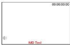
• In 16:9 mode, images are scaled to fill the entire 16:9 screen. In this mode, all OSD features are superimposed on the image. Note that when using a 16:9 input image in this mode, the image will be vertically stretched by approximately 10%.
The diagrams on the following page show how IMD text, timecode, and the audio monitor icon are simultaneously displayed on the screen in each aspect ratio setting. The white area represents the video image.
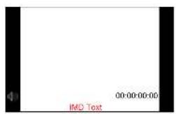
4:3
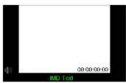
Scaled 4.3
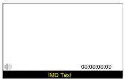
Scaled 16:9 16:9
■ Curtain Color
Use this setting to choose the default color displayed on the screen when no video input is present. Available colors are blue, red, green, white, and black.
■ Sharpness
Sharpness is a type of edge enhancement that can be applied to incoming video signals. Use this setting to increase or decrease the amount of enhancement applied to the image. A value of 000 will make edges appear soft, and a value of 006 will cause edges to be enhanced. The default value is 003. Note: Values higher than 003 will sometimes cause artifacts to appear on the screen if the image includes many natural edges.
Use the Film Mode setting to limit the film mode detection to a specific cadence.
• Auto Deinterlacer automatically identifies the film cadence
2:2 only Deinterlacer only recognizes content originating in 25fps, and uses 2:2 film mode. 24fps content is
ignored
3:2 only Deinterlacer only recognizes content originating in 24fps, and uses 3:2 film mode. 25fps content is ignored.
■ Film Indicator
Use the Film Indicator setting to enable or disable the film mode detection icon. If the Film Indicator is set to On, a green square will appear in the top left corner of the screen whenever a film cadence is detected. The Film indicator can only be turned on only when the Deinterlacer Mode is set to Auto. It is normal for the Film Indicator to sporadically turn on and off, depending on the content.
■ Motion Display
Use the Motion Display options to display inter-field motion as false color [green] on the screen. This feature is used to visualize how the deinterlacer is detecting motion in the content. It is normal for the screen to show large portions of green when viewing moving images.
- Off Motion Display is off.
• Noise Pixels which change value between fields are displayed as green.
• Motion After a noise reduction filter, pixels which change value between fields are displayed as green.
OSD CONFIGURATION SUBMENU
Use the OSD Configuration submenu to select a variety of information to be displayed on the screen.
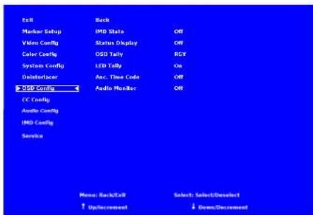
OSD Configuration Submenu
DEINTERLACER SUBMENU
Use the Deinterlacer submenu to control the type of deinterlacing performed on interlaced input signals.
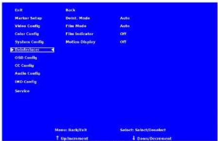
System Configuration Submenu
■ Deinterlacer Mode
Use the Deinterlacer Mode option to set the type of deinterlacing algorithm used:
- In Auto mode, the deinterlacer defaults to Motion Adaptive mode (see below), but uses Film Mode (see below) whenever a film cadence is detected. This is the optimum deinterlacing mode for best picture quality and should be used whenever possible.
- In Motion Adaptive mode, the image processor uses a motion adaptive de-interlacing algorithm. Film cadence detection is disabled. Motion adaptive interlacing uses a variety of real-time algorithms to perform the best possible deinterlacing based on the content.
- In Field to Frame, each incoming field is scaled to a full progressive frame by the scaler. It is normal for the image to appear vertically "bouncy" or as shaking.
- In Interpolate (Bob) mode, each field is scaled to a full progressive frame by interpolating the missing lines from the adjacent lines. It is normal for the image to appear vertically "bouncy" or as shaking.
- In Static Mesh (Weave) mode, the Deinterlacer combines or "weaves" each pair of fields into a progressive frame. It is normal to see jagged artifacts on fast-moving edges.
■ Film Mode
Film mode uses specialized algorithms to correctly deinterlace content that originated in either 24fps or 25fps. Film Mode is automatically entered whenever a film-to-video cadence is detected in the content. Film cadence detection is active whenever the Deinterlace Mode is set to Auto.
COLOR CONFIGURATION SUBMENU
Use the Color Configuration submenu to adjust the color temperature of the display.
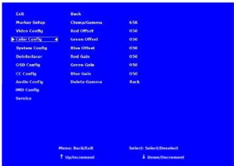
Color Configuration Submenu
■ Ctemp/Gamma
Use this setting to choose one of three color temperature / gamma presets:
D55 (5500K)
• D65 (6500K)
• D93 (9300K)
- Linear (No gamma applied)
■ Red, Green, and Blue Offset
Use the offset controls for red, green, and blue to adjust the color temperature of the display. Each setting adjusts the offset, or brightness, of each individual color component. These settings will affect whichever color temperature preset is selected.
■ Red, Green, and Blue Gain
Use the gain controls for red, green, and blue to adjust the color temperature of the display. Each setting adjusts the gain, or contrast, of each individual color component. These settings will affect whichever color temperature preset is selected.
Use this setting to Delete any custom Gamma tables that have been loaded to the monitor's memory. Note: Once a setting is Deleted, it cannot be recovered from the monitor.
Use the System Configuration submenu to control various system parameters.
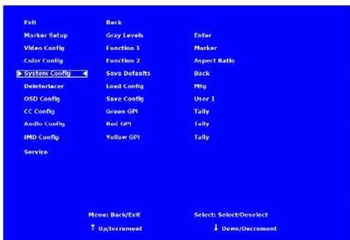
System Configuration Submenu
Gray Levels
Use the Gray Levels menu option to view 256 levels of flat field gray. This feature is useful for color temperature comparison and calibration. The input must be disconnected for the Gray Levels feature to function.
■ User-Definable Function Buttons
Use the Function 1 and Function 2 menu items to define each function button on the front panel of the monitor. The following options are available for each button:
Marker Enable and rotate amongst marker settings (choices depend on aspect ratio setting)
• Center Marker Enable/disable center marker
- Marker Enable Enable/disable screen markers
- Marker Backgrd Rotate amongst marker backgrounds
- IMD Display/hide IMD text
• Anc. Time Code Display/hide time code
• QSD Tally Rotate amongst types of QSD Tally
• Austin Monitor Display/Blvd Austin press post indicator
- Abbid Monitor Display, Hide Abbid presence indicator - Abbid 1.6 Lead one of the Color Customizable objects
User 1-6 Load any of the 6 User Customizable presets
- Mute Enable 100 dB audio signal attenuation - Approx Ratio Toggle between 4x2 and 16x9 resonant
Aspect Ratio Toggle between 4.5 and 16.9 aspect ratios
- Pixel to Pixel Enable/disable Pixel-to-Pixel mode
• Ctemp/Gamma Rotate amongst color temperature settings
Blue Only Enable/disable Blue Only mode
- Monochrome Enable/disable Monochrome mode
■ Save Defaults
Use this setting to save the current values of the Color, Brightness, and Contrast controls as the default values. The defaults can then be accessed by pushing the knob twice.
• Back Exit without making any changes
- Save Save current settings as defaults - Mfg Return to the manufacturer's defaults (all settings at 50).
■ Saving and Loading User Presets
Use the SAVE CONFIG and LOAD CONFIG menus to save current settings to one of 6 presets, or load a preset. Each Preset saves all monitor settings except for IMD configuration.
• Use the LOAD CONFIG menu to load one of presets USR1 – USR6. Factory default settings can also be loaded by selecting MFG. {Factory defaults cannot be overwritten.}
• Use the SAVE CONFIG menu to save the current settings to a preset from USR1-USRG.
■ Green, Red, Yellow GPI
Use the GPI settings to determine the function of a specific Tally pin on the back of the unit. The GPI Pin actions are toggled by bringing the pin LOW. The Red, Green or Yellow Tally pins can activate a variety of settings, listed below.
• Tally Illuminate Green, Red or Yellow Tally LED
- Monochrome Enable/disable Monochrome mode
• Blue Only Enable/disable Blue Only mode
• Pixel to Pixel Enable/disable Pixel to Pixel mode
• Audio Monitor Display/bide Audio Presence Indicator
- Radio Monitor - Display, Hide Audio Presence Links - OSD Tolly - Retain proper turns of OSD Tolly
• OSD Tally A • IMD Display/Side IMD text
- IMD Display/hide IMD text
• CTemp/Gamma Rotate amongst CTemp/Gamma presets
- Aspect Ratio Toggle between 4:3 and 16:9 aspect ratios
• Anc. Time Code Display/hide time code
Marker Level Rotate amongst marker settings
The following settings are activated only when the Green, Red or Yellow Pin is brought into a LOW state by connecting it with one of the GND pins. Once the Tally Pin is brought HIGH again (remove the connection to GND), the settings will be deactivated.
• Monochrome [L] Rotate amongst color temperature settings
- Markers (L) Enable/disable Blue Only mode
Marker Mask 50% III Enable/disable Monochrome mode
• Marker Mask Black (L) Enable/disable Blue Only mode
- Marker Center(L) Enable/disable Monochrome mode
- Warranty
- Dimensions
- Table of Contents
- Specifications
- ■ PANEL
- ■ TALLY/GPI HARDWARE INTERFACE (HD-15)
- ■ RS-422/485 SERIAL INTERFACE (RJ12)
- ELECTRICAL
- MECHANICAL
- ■ COMPLIANCE
- SERVICE SUBMENU
- Overview
- Installation and Initial Setup
- ■ Unpacking
- ■ Installation
- ■ Connections, Power-On and Initial Setup
- Top and Front Panel Features
- Power Button
- ② Menu Navigation Buttons
- User-Definable Function Buttons
- RotoMenu™ Knob
- Image Adjustment Knobs
- LED Tally
- ■ IMD Fixed Color
- ■ IMD Fixed String
- ■ Tally Source
- Standard
- Image Video HW
- Image Video 422
- Standard + IV422
- TSL/MEI 422
- ■ IMD Tally Mode
- ■ IMD Protocol
- Image Video
- TSL v4.0
- MEI
- MEI-Image Video
- ■ IMD ID #
- ■ IMD Group #
- ■ IMD Name (S/N)
- ■ IMD Baud Rate
- ■ IMD Fixed Align
- 3G-SDI Input and Output
- RS-422/485 Serial Interface
- Headphone Jack
- Tally / GPI Interface (HD-15)
- Power Input
- Compatible Input Formats
- SDI/HDSDI Inputs
- 3G-SDI Inputs
- ■ Mute
- Volume
- ■ Audio Delay
- ■ Left Ch. Select
- ■ Right Ch. Select
- IMD CONFIGURATION SUBMENU
- AUDIO CONFIGURATION SUBMENU
- ■ Audio Bars
- MAIN MENU AND NAVIGATION
- Using the menu buttons
- Using the RotoMenu knob
- MARKER SETUP SUBMENU
- Marker Enable
- ■ 16:9 Markers
- CC CONFIGURATION SUBMENU
- CC Mode
- ■ 608 Service
- ■ Transparency
- ■ LED Tally
- ■ Anc. Time Code
- ■ Audio Monitor
- ■ 4:3 Markers
- Marker Background
- ■ Center Marker
- ■ Monochrome Mode
- ■ Blue-Only Mode
- ■ OSD Tally
- ■ IMD State
- ■ Status Display
- ■ Pixel-to-Pixel Mode
- ■ Aspect Ratio Settings
- ■ Curtain Color
- ■ Sharpness
- ■ Film Indicator
- ■ Motion Display
- OSD CONFIGURATION SUBMENU
- DEINTERLACER SUBMENU
- ■ Deinterlacer Mode
- ■ Film Mode
- COLOR CONFIGURATION SUBMENU
- ■ Ctemp/Gamma
- ■ Red, Green, and Blue Offset
- ■ Red, Green, and Blue Gain
- Gray Levels
- ■ User-Definable Function Buttons
- ■ Save Defaults
- ■ Saving and Loading User Presets
- ■ Green, Red, Yellow GPI
Brand : MARSHALL
Model : V-R1041-IMD-3G
Category : Screen