
CAP8 - Electric capacitor BOSS - Free user manual and instructions
Find the device manual for free CAP8 BOSS in PDF.


| Product Type | Power Capacitor |
| Model | CAP8 |
| Brand | Boss |
| Capacitance | 8 Farads (8,000,000 microfarads) |
| Working Voltage | 16 VDC |
| Surge Voltage | 24 VDC |
| ESR (Equivalent Series Resistance) | 0.015 Ohm @ 100Hz/25°C |
| Capacitance Tolerance | +/- 10% |
| Dimensions (W x D x H) | 9-11/16 x 6-3/8 x 2-7/16 inches (245 x 162 x 62 mm) |
| Display | 3-digit super bright blue LED voltage meter |
| Voltage Measurement Accuracy | +/- 0.1 VDC |
| Illumination | Blue illuminated window with light following playing music |
| Automatic Sleep Mode | Yes, when volume is low or no voltage variation |
| Warning Tones | Reverse polarity, over-voltage (>17 VDC), low battery (<10 VDC) |
| Charging Method | Via supplied 1 Watt/51 Ohm resistor; charge before connection |
| Discharge Method | Using supplied resistor across terminals |
| Terminals | Positive (+), Negative (-), Remote power connection |
| Compatible Cable Size | 0 GA and 4 GA |
| Safety Features | Reverse polarity protection, over-voltage shutdown, low battery warning |
| Recommended Use | Supplement car audio system; 1 Farad per 500 watts amplifier power |
| Mounting | Secure with provided hardware, avoid moving parts and moisture |
Frequently Asked Questions - CAP8 BOSS
User questions about CAP8 BOSS
0 question about this device. Answer the ones you know or ask your own.
Ask a new question about this device
Download the instructions for your Electric capacitor in PDF format for free! Find your manual CAP8 - BOSS and take your electronic device back in hand. On this page are published all the documents necessary for the use of your device. CAP8 by BOSS.
USER MANUAL CAP8 BOSS
Congratulations on your purchase of a 3D Driver Capacitor System.
It has been designed, engineered and manufactured to bring you the highest level of performance and quality, and will afford you years of listening pleasure.
Thank you for making a

your choice for car audio entertainment!
USER'S MANUAL
page CONTENTS
2 Why use a power capacitor?
2 Features
4 Installation precautions
6 Important note about charging the capacitor
6 CAP18 and CAP30 electrical connections
7 CAP8 electrical connections
8 Charging the capacitor
9 Discharging the capacitor safely before removal
10 Specifications
Why use a power capacitor?
This power capacity is an energy storage device. It is designed to supplement you car's charging system, when your audio amplifier places a high current demand upon it. This occurs, for example, when the music you are playing contains a loud, transient, deep bass signal.
The overall bass response of your system will be enhanced by using this device. Since automotive batteries are not designed to deliver the current required by modern car audio systems, a capacitor such as this one, which is capable of discharging extremely rapidly on demand, is a logical addition to your audio system.
In addition, this capacitor can filter out the AC voltage induced in the amplifier's power supply. Unchecked, this voltage can cause audible noise in the sound system. It is recommended to use a capacitor with a minimum of one farad (1F) for each 500 watts of amplifier power. (you can never have too much capacitance for any audio system).
The BOSS capacitors feature a digital voltage display.
Features
Your new power capacitor system features the following:
• 3-digit, super bright blue LED voltage meter
• Voltage measurement accurate to +/- 0.1VDC
- Blue illuminated window with light following playing music
• Automatic sleep status when volume is low or there is no voltage variation present
- Warning tones for the following detected conditions:
Reverse polarity connection
Over-voltage limit (above 17VDC)
Low battery voltage (below 10VDC)
General precautions
Before installing and using your new BOSS RECHO SYSTEMS capacitor, please become fa- miliar with all the information con- tained in this manual.
Please keep this manual in a safe place for future reference.
- Do not open or attempt to repair this unit yourself. Dangerous high voltages are present which may result in electric shock. Refer any repairs to a qualified service technician.
- To avoid risk of electronic shock or damage to the unit, do not permit any of this equipment to become damp or wet from water or drinks. If this does occur, immediately unplug the power wires and send the product to your local dealer or service center as soon as possible.
- If there is smoke or any peculiar odor present during use or if there is damage to any of the component enclosures, immediately unplug the power cord and send the product to your local dealer or service center as soon as possible.
SHOCK HAZARD! Do not open the case of this product. There are dangerous voltages present within the unit. There are no user-serviceable parts within the unit.
WARNING! This power capacitor may explode and cause serious injury or death if abused or connected improperly.
Refer to this installation manual for correct procedures when making connections, and for charging and discharging the capacitor. Never expose the capacitor to voltages higher than specified!
Installation precautions
Prior to installing and connecting the capacitor, please study the drawing below and become familiar with the physical features of the capacitor.
Securely mount the capacitor using the hardware provided. Be careful when choosing a mounting location to avoid moving parts, and possible exposure to moisture.
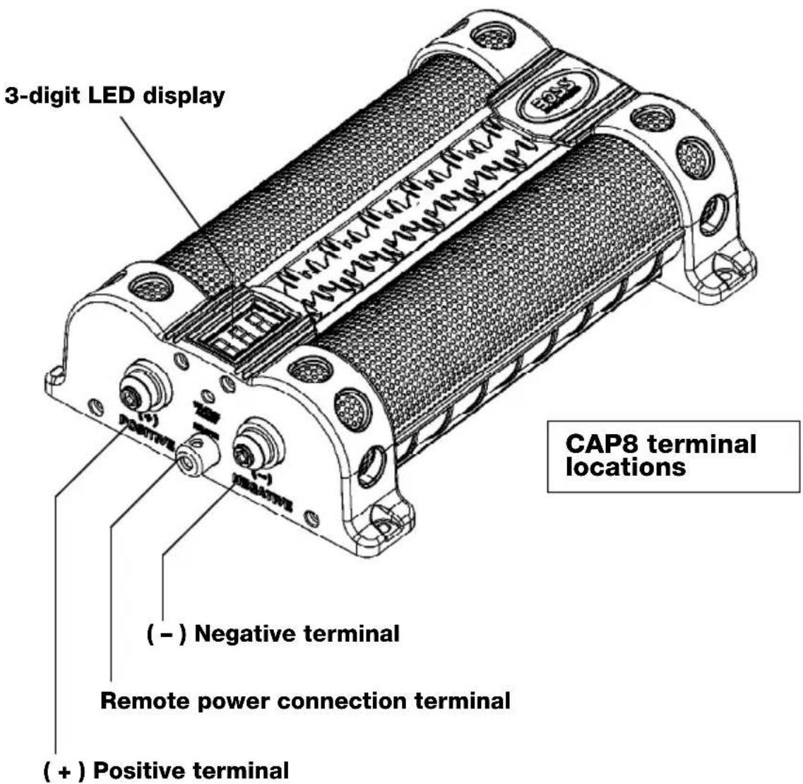

Important note about charging the capacitor
This capacitor must be charged BEFORE connecting the POWER and GROUND cable to the capacitor.
Failure to charge the capacitor will result in a large spark generated form the rapid inflow of current which can be very dangerous.
Electrical connections for CAP18 or CAP30
Make all wiring connections as shown in the diagram, but do not attach the incoming positive cable to the capacitor positive terminal.
Connect the positive terminal only after following the instructions for charging the capacitor on page 8.

flowchart
graph TD
    A["HEAD UNIT"] --> B["AMPLIFIER #1"]
    B --> C["REMOTE TERMINAL"]
    B --> D["RELAY"]
    B --> E["AMPLIFIER POWER TERMINALS"]
    B --> F["DISTRIBUTION BLOCK (-)"]
    B --> G["DISTRIBUTION BLOCK (+)"]
    B --> H["AMPLIFIER POWER TERMINALS"]
    B --> I["FUSE/FUSE BLOCK"]
    I --> J["CAR BATTERY"]
    J --> K["CHASSIS GROUND POINT"]
    K --> L["CHASSIS GROUND POINT"]
    L --> M["MAKE THIS CONNECTION ONLY AFTER CHARGING THE CAPACITOR!!!"]
WIRING DIAGRAM: CAP18 or CAP30 In Two Amplifier System
Electrical connections for CAP8
Make all wiring connections as shown in the diagram, but do not attach the incoming positive cable to the capacitor positive terminal.
Connect the positive terminal only after following the instructions for charging the capacitor on page 8.

flowchart
graph TD
    A["HEAD UNIT"] --> B["AMPLIFIER"]
    B --> C["FUSE/FUSE BLOCK"]
    C --> D["CAR BATTERY"]
    D --> E["CHASSIS GROUND POINT"]
    B --> F["DISTRIBUTION BLOCK (+)"]
    F --> G["+"]
    G --> H["CHASSIS GROUND POINT"]
    B --> I["DISTRIBUTION BLOCK (-)"]
    I --> J["+"]
    J --> K["CHASSIS GROUND POINT"]
    style A fill:#f9f,stroke:#333
    style B fill:#ccf,stroke:#333
    style C fill:#cfc,stroke:#333
    style D fill:#fcc,stroke:#333
    style E fill:#cff,stroke:#333
    style F fill:#ffc,stroke:#333
    style G fill:#cfc,stroke:#333
    style H fill:#fcc,stroke:#333
    style I fill:#ffc,stroke:#333
    style J fill:#cfc,stroke:#333
    style K fill:#fcc,stroke:#333
WIRING DIAGRAM: CAP8 In Single Amplifier System
Charging the capacitor
As noted earlier, make all connections according to the diagram(s) on the preceding pages EXCEPT for the POSITIVE (+) connection to the capacitor. To charge the capacitor, follow these steps:
1) Pick up the cable coming from the POSITIVE (+) battery terminal.
2) Place the supplied charging resistor between the end of this cable and the positive terminal of the capacitor. The capacitor will begin charging. Charging generally takes 5-60 seconds. During charging, the voltage shown in the 3-digit display will rise rapidly, then slow as it approaches the voltage of your vehicle's battery. When fully charged, the displayed voltage will stop rising.
If you have a voltmeter, you can first measure the voltage of your car battery. Then you will know with accuracy that the capacitor is fully charged.
CAUTION!! During charging, the resistor will become hot. This is normal, but exercise caution during the charging process.
3) After charging is complete, remove the resistor from the incoming positive cable, and IMMEDIATELY connect it to the positive terminal of the capacitor.
The installation and charging process are now complete, and you can begin using your audio system and enjoying the benefits of your new system enhancement.

Discharging the capacitor
CAUTION!!
Never remove the capacitor without discharging the stored power. It can give a dangerous electrical shock, even after disconnection.
To safely discharge and disconnect the capacitor, follow these steps:
1) Disconnect cables from the capacitor in the following order:
POSITIVE cable GROUND cable REMOTE cable
2) Using the resistor provided, touch one lead to the POSITIVE (+) terminal and one lead to the NEGATIVE (-) terminal.
CAUTION!! During discharging, the resistor will become hot. This is normal, but exercise caution during the discharging process.
After 1-5 minutes, the capacitor will be discharged (there is no sound from the buzzer) and you can safely remove and handle it.

| MODEL | 30 Farad Super Hybrid Power Capacitor CAP30 | 18 Farad Super Hybrid Power Capacitor CAP18 | 8 Farad Power Capacitor CAP8 |
| Capacitance, microfarads | 30,000,000 | 18,000,000 | 8,000,000 |
| Working voltage | 16VDC | 16VDC | 16VDC |
| Surge voltage | 24VDC24VDC24VDC | ||
| ESR (Equivalent series resistance) | — 0.015 Ohm @ 100Hz/25°C — | ||
| Capacitance tolerance | — +/- 10% — | ||
Dimensions, inches (mm)
| CAP30 | 11-7/16 x 7-3/4 x 3-5/32 | (29 x 19.7 x 8) |
| CAP18 | 10-7/8 x 7-3/4 x 3-5/16 | (27.5 x 19.7 x 8) |
| CAP8 | 9-11/16 x 6-3/8 x 2-7/16 | (24.5 x 16.2 x 6.2) |
All specifications subject to change without notice.
- Congratulations on your purchase of a 3D Driver Capacitor System.
- USER'S MANUAL
- page CONTENTS
- Why use a power capacitor?
- Features
- General precautions
- Please keep this manual in a safe place for future reference.
- WARNING! This power capacitor may explode and cause serious injury or death if abused or connected improperly.
- Installation precautions
- Important note about charging the capacitor
- Electrical connections for CAP18 or CAP30
- Electrical connections for CAP8
- Charging the capacitor
- Discharging the capacitor
- CAUTION!!
Brand : BOSS
Model : CAP8
Category : Electric capacitor