FAP40T - Pregnant Atlas Sound - Free user manual and instructions
Find the device manual for free FAP40T Atlas Sound in PDF.


| Product Type | In-Ceiling Speaker System |
| Speaker Size | 4 inches |
| Frequency Response | 120 Hz - 15 kHz |
| Sensitivity (1W/1M) | 86 dB |
| Power Taps (70.7V) | 1W, 2W, 4W, 8W, 16W |
| Power Taps (100V) | 2W, 4W, 8W, 16W |
| 8Ω Bypass | Yes |
| Max Power (8Ω) | 16 W RMS |
| Cutout Diameter | 6 5/16 in (160.3 mm) |
| Ceiling Material Thickness | Up to 1 1/4 in (standard), up to 2 in (with flipped dog legs) |
| Mounting Types | Drop tile ceiling, drywall (existing or new construction) |
| Included Accessories | Tile bridge, template, press-fit grille |
| Connection Type | Barrier block (screw terminal), conduit knockout (1/2 in) |
| Safety Features | Suspension ring for seismic safety |
| Dog Leg Screws | Three, adjustable for different ceiling thicknesses |
| Transformer | Internal, with tap selector switch |
Frequently Asked Questions - FAP40T Atlas Sound
User questions about FAP40T Atlas Sound
0 question about this device. Answer the ones you know or ask your own.
Ask a new question about this device
Download the instructions for your Pregnant in PDF format for free! Find your manual FAP40T - Atlas Sound and take your electronic device back in hand. On this page are published all the documents necessary for the use of your device. FAP40T by Atlas Sound.
USER MANUAL FAP40T Atlas Sound
4" In-Ceiling Speaker System
Drop Tile Ceiling Installation:
- Remove the 2' × 2' or 2' × 4' tile.
- Align the tile bridge on the rear of the tile in the desired position.
- Using the template provided mark the cutout circle with a marker and cut a 6^5/16 (160.3mm) hole.
- Replace tile into grid.
- Bring service loop from rear of the tile, through the tile bridge to the access panel located on the side of the Enclosure. Terminate the service loop to the barrier block connection provided. (Red dot = "+" please note polarity). A 18 " through hole is provided to facilitate conduit. A UL recognized conduit connector should be used to terminate conduit. Connection cavity is not intended for use as a junction box.
- Insert the enclosure through the front of the tile. Using a standard #2 Phillips screwdriver or screw-gun tighten the three dog leg assemblies until they engage the tile bridge assembly. DO NOT OVER TIGHTEN DOG LEG SCREWS!
- Adjust the front mounted switch to the desired tap setting.
NOTE: An 8Ω setting is included on the selector switch which bypasses the internal transformer for applications where the FAP40T is to be directly coupled to 8Ω amplifiers. - Install the press-fit grille into the front bezel ring. Push the baffle upwards until the baffle is flush with the bezel ring.
- For safety and seismic considerations, a suspension ring is integrated into the input panel section of the unit. Atlas Sound strongly suggests that a support wire be installed from this support point to a suitable anchor point above the ceiling grid. In drop tile applications, this wire can usually be installed from an adjacent tile access near the speaker location.
- Using the template provided mark the cutout circle in the desired mounting location and cut a 6516 " (160.3mm) hole.
- Bring service loop from through the hole to the access panel located on the side of the enclosure. Terminate the service loop to the barrier block connection provided (Red dot = "+" please note polarity). A 18 " through hole is provided to facilitate conduit. A UL recognized conduit connector should be used to terminate conduit. Connection cavity is not intended for use as a junction box.
- Insert the enclosure into hole. Using a standard #2 Phillips screw-driver or screw-gun tighten the three dog leg assemblies until they engage the tile bridge assembly. DO NOT OVER TIGHTEN DOG LEG SCREWS!
- Adjust the front mounted switch to the desired setting. NOTE: A 8Ω setting is included on the selector switch which bypasses the internal transformer for applications where the FAP40 is to be directly coupled to 8Ω amplifiers.
Existing Construction Dry Wall ("Hard Deck") Installation
- Install the press-fit grille into the front bezel ring. Push the baffle upwards until the baffle is flush with the bezel ring.
New Construction (Drywall Ceilings)
Use of the optional FA-TR4 new construction bracket essentially reserves the speaker mounting location prior to drywall installation in new construction. The bracket mounts between 16" or 24" OC studs and includes a 3 / 8" downward lip to provide a template for the drywall installers to cut around. For final installation please follow the instructions below.
Note: The tile bridge is not to be used in new construction applications where the new construction bracket is utilized.
- Bring service loop from through the hole in ceiling provided by the pre construction bracket to the access panel located on the side of the Enclosure. Terminate the service loop to the barrier block connection provided (Red dot = "+" please note polarity). A 38 " through hole is provided to facilitate conduit. A UL recognized conduit connector should be used to terminate conduit. Connection cavity is not intended for use as a junction box.
-
Insert the speaker assembly into hole. Using a standard #2 Phillips screwdriver or screw-gun tighten the three dog leg assemblies until they engage the ring provided on the new construction bracket. DO NOT OVER TIGHTEN DOG LEG SCREWS!
-
Adjust the front mounted switch to the desired tap setting.
NOTE: An 8Ω setting is included on the selector switch which bypasses the internal transformer for applications where the FAP40 is to be directly coupled to 8Ω amplifiers.
- Install the press-fit grille into the front bezel ring. Push the baffle upwards until the baffle is flush with the bezel ring.
NOTE:
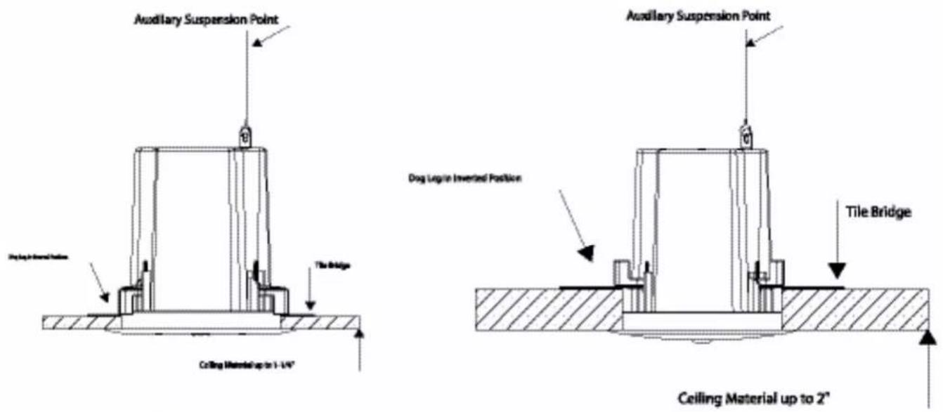
- Dog legs will accommodate ceiling material thickness up to 1 14 " as shipped from the factory.
- For thicker ceiling materials (up to 2") simply unscrew and flip the doglegs.
• DO NOT OVER TIGHTEN DOG LEGS IN ANY CONFIGURATION!
• *DO NOT USE 8Ω SETTING WITH 70.7V/100V SYSTEMS!
• *DO NOT OVERPOWER IN 8Ω CONFIGURATION!
• AMPLIFIER OUTPUT SHOULD NOT EXCEED 16 WATTS RMS @ 8Ω PER SPEAKER - A UL recognized conduit clamp must be used for conduit connections.
- Cable connection cavity is not intended to be used as a junction box.
• FA-TR4 not tested or evaluated by Underwriters Laboratories (UL)
Specifications
Frequency Response 120Hz - 15kHz
Sensitivity 86dB (1W / 1M)
FAP40T
4" In-Ceiling Speaker System
Typical Parallel Hookup of Full Range 70.7V / 100V Speakers
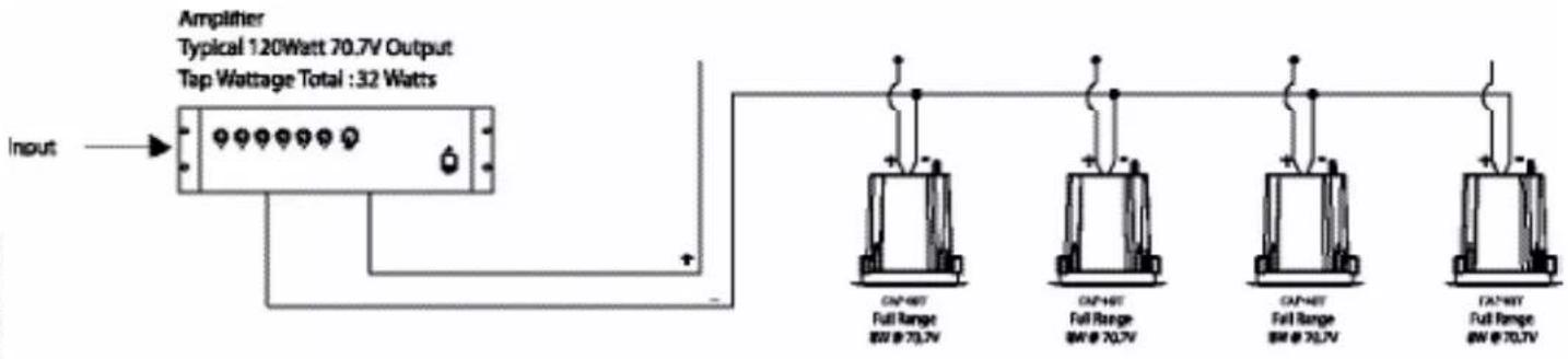
Tap Selector Switch Position
| Amp Output 1 | 2 3 4 5 6 | |||||
| 70.7V | 1 watt 2 watts 4 watts 8 watts 16 watts | Bypass (8Ω) | ||||
| 100V | 2 watts 4 watts 8 watts 16 watts N/A | Bypass (8Ω) | ||||

Brand : Atlas Sound
Model : FAP40T
Category : Pregnant