
SurgeArrest - Surge protector APC - Free user manual and instructions
Find the device manual for free SurgeArrest APC in PDF.


| Type of product | Surge protector |
| Brand | APC |
| Model | SurgeArrest |
| Dimensions (approx.) | 12 x 6 x 4 inches (30.5 x 15.2 x 10.2 cm) |
| Weight | 2 lb (0.9 kg) |
| Power rating | 120 V, 15 A |
| Surge energy rating | 1080 Joules |
| Outlets | 6 grounded outlets |
| Cord length | 6 ft (1.8 m) |
| Indicator lights | Protection status, Ground fault |
| Circuit breaker | 15 A resettable |
| EMI/RFI filtering | Yes |
| Maintenance | Wipe with dry cloth; do not use liquids |
| Cleaning | Unplug before cleaning; use soft dry cloth |
| Safety certifications | UL 1449, cUL |
| Spare parts | Not user-serviceable; replace unit if damaged |
| Reparability | No user-repairable parts; contact APC for service |
| Warranty | Lifetime warranty on product, $150k connected equipment warranty |
| Operating temperature | 32°F to 104°F (0°C to 40°C) |
| Storage temperature | -4°F to 149°F (-20°C to 65°C) |
| Relative humidity | 0% to 95% (non-condensing) |
Frequently Asked Questions - SurgeArrest APC
User questions about SurgeArrest APC
0 question about this device. Answer the ones you know or ask your own.
Ask a new question about this device
Download the instructions for your Surge protector in PDF format for free! Find your manual SurgeArrest - APC and take your electronic device back in hand. On this page are published all the documents necessary for the use of your device. SurgeArrest by APC.
USER MANUAL SurgeArrest APC
Technical Compliance Statement FCC Test Report
For the following information
Ref. File No.: C1M2208189
Product : Relocatable Power Taps
Model Number : P11U2
Serial No : P11U2xxxxxxxxx ("x" can be 0-9, A-Z," - " or blank)
Brand : APC or APC by Schneider Electric
Applicant : American Power Conversion Holdings Inc., Taiwan Branch
Rules and Standards : Title 47 FCC CFR, Part 15, Subpart B, Class B ANSI C63.4-2014/ ANSI C63.4a-2017
We hereby certify that the above product has been tested by us and complied with above FCC official limits. The test was performed according to the procedures ANSI C63.4-2014/ ANSI C63.4a-2017. The equipment might be marketed in US in accordance with the rules of 47 CFR FCC Part 2 regulations.
The test data and results are issued on the test report no. EM-F160444B.
Signature

Test Laboratory:
AUDIX Technology Corporation, EMC Department
NVLAP Lab. Code: 200077-0
FCC OET Designation: TW1004 & TW1090
Web Site: www.audixtech.com
The statement is based on a single evaluation of one sample of the above-mentioned products. It does not imply an assessment of the whole production and does not permit the use of the test lab logo.
TEST REPORT
Product: Relocatable Power Taps
Model: P11U2
Serial No.: P11U2xxxxxxxxx ("x" can be 0-9, A-Z," - " or blank)
Brand : APC or APC by Schneider Electric
Applicant for:
American Power Conversion Holdings Inc., Taiwan Branch 5F., No.189, Sec. 2, Jiuzong Rd., Neihu District, Taipei City 11494, Taiwan
Prepared by:
Audix Technology Corporation, EMC Department
No. 491, Zhongfu Rd., Linkou Dist.,
New Taipei City 244, Taiwan


Testing Laboratory
1724

NVLAP LAB CODE 200077-0
File No. : C1M2208189
Report No. : EM-F160444B
Date of Report of Rev. B : 2022.08.26
The test report is based on a single evaluation of one sample of the above-mentioned products. It does not imply an assessment of the whole production and does not permit the use of the test lab logo.
The report must not be used by the client to claim product certification, approval, or endorsement by NVLAP, NIST, or any agency of the U.S. Government.
Test Report
Applicant : American Power Conversion Holdings Inc.,
Taiwan Branch
EUT Description
(1) Product : Relocatable Power Taps
(2) Model : P11U2
(3) Serial No : P11U2xxxxxxxxx ("x" can be 0-9, A-Z," - " or blank)
(4) Brand : APC or APC by Schneider Electric
(5) Power Rating : 120V, 50/60Hz
Rules of Compliance and Applicable Standards:
Title 47 FCC CFR, Part 15, Subpart B, Class B ANSI C63.4-2014 / ANSI C63.4a-2017
The device described above was tested by Audix Technology Corporation to determine the maximum emission levels emanating from the device. All of the tests were requested by the applicant and the results thereof based upon the information that the applicant provided to us. We, Audix Technology Corporation assumes full responsibility for the accuracy and completeness of these measurements. This report is made under FCC Part 2.938 and shows that the EUT is technically compliance with the class B limit for both FCC rule standard described as above.
No modifications were required during testing to bring this product into compliance.
This report applies to above tested sample only and shall not be reproduced in part without written approval of Audix Technology Corporation.
This report is based on report of EM-F160444 & EM-F160444A.
Date of Report of Rev. B: 2022.08.26
Reviewed by:
Albee Lee
(Albee Lee/Administrator)
Approved by:
Oluo Deng
(Alex Deng/Deputy Manager)
Name of the Representative of the Responsible Party:
Signature:
Table of Content
-
Revision of Test Report......4
-
Summary of Test Result...... 5
2.1. Test Result....5
2.2. Description of Test Firm....6
- General Information....7
3.1. Description of Application 7
3.2. Description of the EUT 7
3.3. Highest Frequency within EUT 8
3.4. Determination of Worse Case Operating Modes....8
3.5. Final Test Configuration 8
- Measurement Arrangement....9
4.1. Equipment and cables arrangement 9
4.2. Method of Exercising EUT 9
4.3. List of Supported Units under Test.... 10
4.4. List of Used Cables under Test.... 10
- Measurement of Conducted Emissions.... 11
5.1. List of Test Instruments.... 11
5.2. Test Setup.... 11
5.3. Power-line Conducted Emission Limits 12
5.4. Measurement Procedure 12
5.5. Measurement Result.... 13
- Measurement of Radiated Emissions 15
6.1. List of Test Instruments.... 15
6.2. Test Setup.... 16
6.3. Radiation Emission Limits 17
6.4. Measurement Procedure 18
6.5. Measurement Result.... 19
-
Measurement Uncertainty List.... 21
-
Photographs...... 24
8.1. Powerline Conducted Emission Measurement.... 24
8.2. Radiated Emissions Measurement 25
APPENDIX (Photos of EUT)
1. Revision of Test Report
| Issued Date | Revision Summary Report Number | |
| 2016. 07. 07 | Original Report. | EM-F160444 |
| 2021. 05. 20 | 1. To update standard.2. To modify address of applicant. | EM-F160444A |
| 2022. 08. 26 | 1.To add a USB charger module type.2.To deleted ICES-003 standard. | EM-F160444B |
2. Summary of Test Result
2.1. Test Result
| Test Item | Referred Rules/Standard | Limit | Result |
| Power-line conducted emission | Title 47 FCC CFR Part 15 Subpart B | Class B | Pass |
| Margin 2.29dB at 0.551MHz | |||
| Radiated emission (30 – 1000MHz) | Title 47 FCC CFR Part 15 Subpart B | Class B | Pass |
| Margin 5.84dB at 119.562MHz (Vertical, 1m/25°) | |||
| Radiated emission (Above 1GHz) | Title 47 FCC CFR Part 15 Subpart B | Class B | N/A |
| Note :The uncertainties value is not used in determining the result.N/A is an abbreviation for Not Applicable.Special measures: NoneDecision and justification not to measure: None | |||
2.2. Description of Test Firm
| Name of Test Firm | Audix Technology Corporation / EMC DepartmentNo. 491, Zhongfu Rd., Linkou Dist., New Taipei City 244, TaiwanTel: +886-2-26092133Fax: +886-2-26099303Website : www.audixtech.comContact e-mail: attemc_report@audixtech.com |
| Accreditations | The laboratory is accredited by following organizations under ISO/IEC 17025:2017(1) NVLAP(USA)NVLAP Lab Code 200077-0(2) TAF(Taiwan)No. 1724 |
| Test Facilities | FCC OET Designation Number under APEC MRA by BSMI is : TW1004 & TW1090(1) No. 3 Shielding Room(2) No. 6 Open Area Test Site |
3. General Information
3.1. Description of Application
| Applicant | American Power Conversion Holdings Inc., Taiwan Branch5F., No.189, Sec. 2, Jiuzong Rd., Neihu District, Taipei City 11494, Taiwan | ||
| Product | Relocatable | Power | Taps |
| Brand APC or APC | by Schneider Electric | ||
| Model Number P11 | U2 | ||
| Serial No | P11U2xxxxxxxxx (“x” can be 0-9, A-Z,” - “ or blank) | ||
3.2. Description of the EUT
| Test Model P11U2 | |
| Serial Number N/A | |
| Power Rating 120V | 50/60Hz |
| Firmware Version N/A | |
| Sample Status Trial | Sample |
| Date of Receipt of Rev. B | 2022. 08. 15 |
| Date of Test of Rev. B | 2022. 08. 17 |
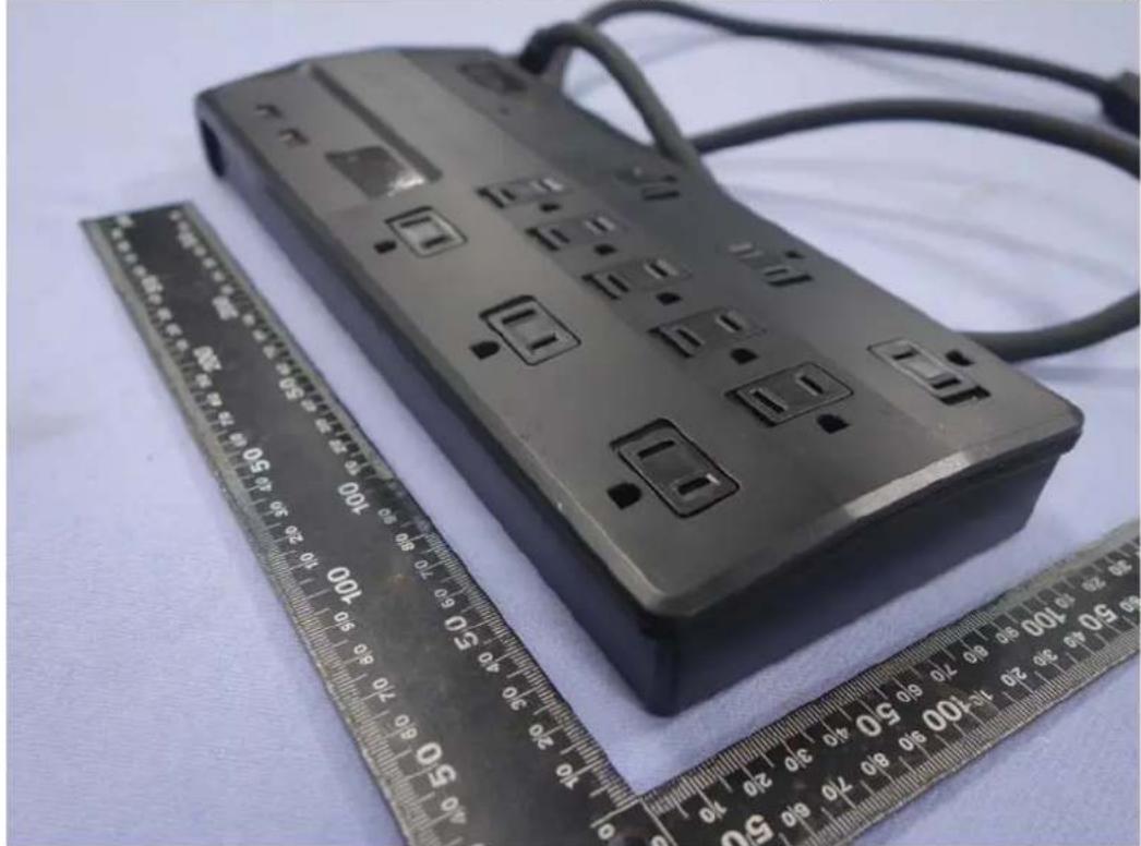
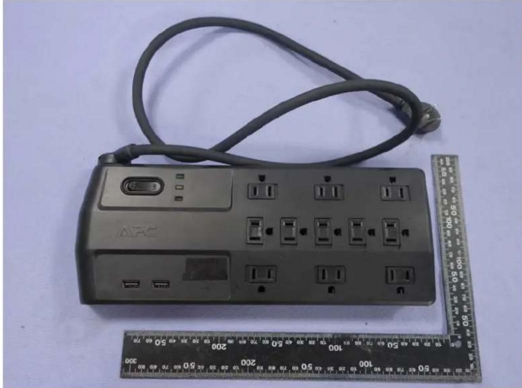
| I/O Ports List | • AC Surge Protected Outlets x11• USB x2 (DC 5V, 2.4A) |
| Accessories Supplied | • AC Power Cord(3C) |
3.3. Highest Frequency within EUT
The highest frequency operating in EUT is less than 108MHz. The highest measured frequency is performed according to the requirement of FCC Part 15.33.
3.4. Determination of Worse Case Operating Modes
● The EUT is an additional version with original report number EM-F160444.
The differences with original reports is:
-
To add a USB charger module type.
-
To deleted ICES-003 standard.
● Depending on all different, the EUT was re-tested to comply with the standards requirements. The supplementary test data are recorded in this report of EM-F160444B.
3.5. Final Test Configuration
| Test Item Operating of EUT | |
| Power-line conducted emission | Load With Lamp + R Load |
| Radiated emission(30 – 1000MHz) | Load With Lamp + R Load |
4. Measurement Arrangement
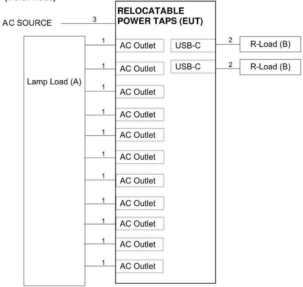
4.1. Equipment and cables arrangement
- Connection Diagram of EUT and Peripheral Devices
(worst mode)
flowchart
graph TD
    A["AC SOURCE"] --> B["Lamp Load (A)"]
    B --> C["RELOCATABLE POWER TAPS (EUT)"]
    C --> D["2 R-Load (B)"]
    C --> E["2 R-Load (B)"]
    C --> F["1 AC Outlet"]
    C --> G["1 AC Outlet"]
    C --> H["1 AC Outlet"]
    C --> I["1 AC Outlet"]
    C --> J["1 AC Outlet"]
    C --> K["1 AC Outlet"]
    C --> L["1 AC Outlet"]
    C --> M["1 AC Outlet"]
    C --> N["1 AC Outlet"]
    C --> O["1 AC Outlet"]
    C --> P["1 AC Outlet"]
4.2. Method of Exercising EUT
The methods for exercising the EUT during the measurement specified in ANSI C63.4-2014 clause 11.2, 11.3 and figure 16 were used.
-
To turn on the power of all equipments.
-
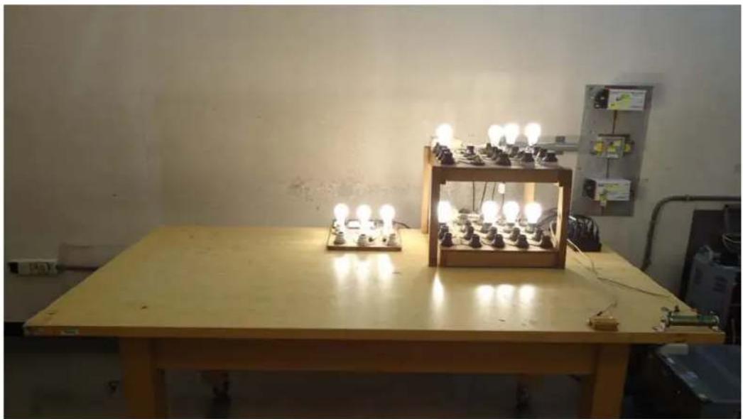
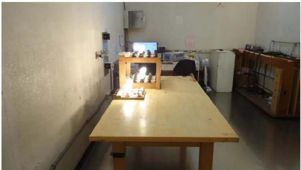
The EUT (Relocatable Power Taps) was linked to bulbs load and R-Load was tested in full load mode during the testing.
4.3. List of Supported Units under Test
| Item | Product | Brand | Model No. | Serial No. | Approval |
| A Lamp Load (60W*11) | N/A | N/A | N/A | N/A | |
| B | R-Load | N/A | N/A | N/A | N/A |
| C | R-Load | N/A | N/A | N/A | N/A |
4.4. List of Used Cables under Test
| Item | Type Qty. | Length (m) | Shielding (Yes/No) | Cores (Qty.) | Remark | |
| 1 | AC Power Cord 11 | 1.8 No 0 | Provided by LAB | |||
| 2 | USB-C Cable | 2 | 1.0 | Yes | 0 | Provided by LAB |
| 3 | AC Power Cord (3C) | 1 | 1.0 | No | 0 | Accessories of EUT |
5. Measurement of Conducted Emissions
5.1. List of Test Instruments
| Item | Equipment | Manufacture | Model No. | Serial No. | Cal. Date | Cal. Interval |
| 1 | Test Receiver R&S | ESR3 101772 | 2022. 07. 22 | 1 Year | ||
| 2 | A.M.N. R&S ENV4 | 200 825358/003 | 2022. 05. | 11 1 Year | ||
| 3 | L.I.S.N. | Kyoritsu | KNW-407 | 8-1539-2 | 2021. 12. 19 | 1 Year |
| 4 | Pulse Limiter | R&S | ESH3-Z2 | 100041 | 2021. 12. 23 | 1 Year |
| 5 | Signal Cable | CDM Elec-tronics, Inc. | RG-142 | CE-02 | 2022. 01. 20 | 1 Year |
| 6 | Digital Ther-mo-Hygro Meter | WISEWIND | 5330 | No.3 S/R | 2022. 04. 14 | 1 Year |
| 7 | Test Software | Audix | e3 | V6.120703a | N.C.R. | N.C.R. |
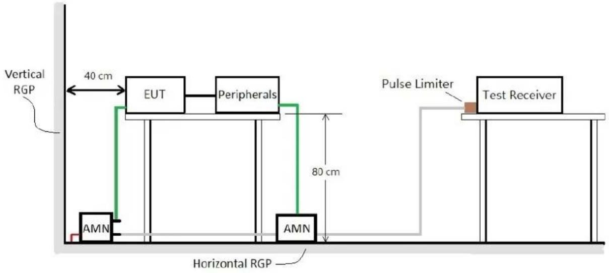
5.2. Test Setup
The EUT and test equipment were configured in accordance with the requirement of ANSI C63.4-2014 clause 5.2.
flowchart
graph TD
    A["Vertical RGP"] --> B["EUT"]
    B --> C["Peripherals"]
    C --> D["AMN"]
    D --> E["Horizontal RGP"]
    E --> F["Pulse Limiter"]
    F --> G["Test Receiver"]
    style A fill:#f9f,stroke:#333
    style B fill:#ccf,stroke:#333
    style C fill:#cfc,stroke:#333
    style D fill:#fcc,stroke:#333
    style E fill:#cff,stroke:#333
    style F fill:#ffc,stroke:#333
    style G fill:#fcc,stroke:#333
5.3. Power-line Conducted Emission Limits
- For FCC §15.107
| Frequency Range (MHz) | Class A Limits Class B Limits | |||
| Quasi Peak dB(μV) | Average dB(μV) | Quasi Peak dB(μV) | Average dB(μV) | |
| 0.15 – 0.50 79 66 | 66 – 56* 56 | -46* | ||
| 0.50 – 5.0 | 73 | 60 | 56 | 46 |
| 5.0 – 30 60 50 | ||||
Note: * Decreases with the logarithm of the frequency.
5.4. Measurement Procedure
The power-line conducted emission measurement was performed in accordance with the procedure of ANSI C63.4-2014 clause 7.3.
- Setup the EUT and associated equipment described as section 4.1, and they were located 40cm from the vertical conducting plane.
- Connect the EUT power cord to the main A.M.N and associated equipment to the second A.M.N. All ports of the A.M.N not connecting to the measuring equipment was terminated into 50 ohm resistive load.
- Setup the resolution bandwidth of the test receiver at 9kHz (while testing within 0.15 to 30MHz).
- Operate the EUT system as described in section 4.2.
- Both sides of A.C. line were checked for maximum conducted interference. In order to find the maximum emission, all of the interconnecting cables were manipulated.
- For the exploratory measurement, determine the highest emission amplitude relative to the limit on each of the EUT power cord with the peak detector by each of the EUT operation over the specified frequency range and record it.
- For final measurement, select the EUT operation mode that produced the highest amplitude in the exploratory measurement to determine the highest emissions with each specified detector and record it. All of the current-carrying conductors of each of the EUT power cords, except the ground conductor, must be measured over the specified frequency range.
● The measurement result was calculated by following formula:
Emission Level (dBμV) = Reading (Receiver) (dBμV) + Factor (A.M.N) (dB) + Cable Loss (dB) + Pulse Limiter (dB)
- If the average limit is met when using a Quasi-Peak detector receiver, the EUT is deemed to meet both limits and measurement with the average detector is unnecessary.
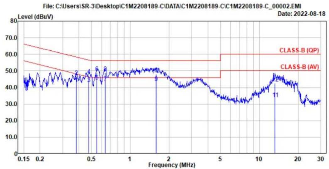
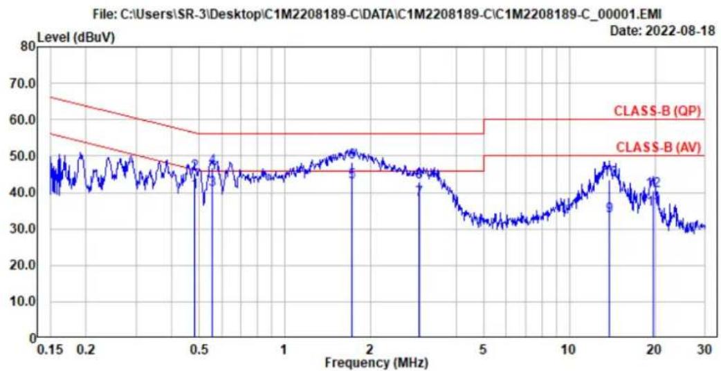
5.5. Measurement Result
The following data are the worst emissions based on the prescan measurement result.
| Test Phase Neutral Test Result Pass | ||
| Test Mode Mode 1, Load With Lamp + R Load | ||
line
| Frequency (MHz) | Level (dBuV) | | --------------- | ------------ | | 0.15 | ~45 | | 0.2 | ~48 | | 0.5 | ~50 | | 1 | ~50 | | 5 | ~45 | | 10 | ~35 | | 20 | ~30 | | 30 | ~30 || Site No. | : No.3 Shielded Room | Data No. : 2 |
| Instrument 1 | : Receiver ESR(772) | |
| Instrument 2 | : ENV4200 (8-003)(A)|CE-02|ESH3-Z2 (041) | |
| Limit | : CLASS-B (QP) | Phase : Neutral |
| Environment | : 25°C / 48% | Engineer : John He |
| EUT Model | : P11U2 | Test Rating : 120V/60Hz |
| Test Mode | : Mode 1 |
| Freq. (MHz) | AMN Factor (dB) | Cable Loss (dB) | Pulse Att. (dB) | Reading (dBμV) | Emission Level (dBμV) | Limits (dBμV) | Margin (dB) | Remark | |
| 1 | 0.383 | 10.24 | 0.02 | 9.86 | 22.03 | 42.15 | 48.22 | 6.07 | Average |
| 2 | 0.383 | 10.24 | 0.02 | 9.86 | 26.49 | 46.61 | 58.22 | 11.61 | QP |
| 3 | 0.479 | 10.24 | 0.02 | 9.86 | 22.03 | 42.15 | 46.35 | 4.20 | Average |
| 4 | 0.479 | 10.24 | 0.02 | 9.86 | 27.29 | 47.41 | 56.35 | 8.94 | QP |
| 5 | 0.551 | 10.24 | 0.02 | 9.86 | 23.59 | 43.71 | 46.00 | 2.29 | Average |
| 6 | 0.551 | 10.24 | 0.02 | 9.86 | 28.75 | 48.87 | 56.00 | 7.13 | QP |
| 7 | 0.643 | 10.24 | 0.03 | 9.86 | 22.60 | 42.73 | 46.00 | 3.27 | Average |
| 8 | 0.643 | 10.24 | 0.03 | 9.86 | 28.72 | 48.85 | 56.00 | 7.15 | QP |
| 9 | 1.593 | 10.25 | 0.04 | 9.86 | 22.71 | 42.86 | 46.00 | 3.14 | Average |
| 10 | 1.593 | 10.25 | 0.04 | 9.86 | 27.90 | 48.05 | 56.00 | 7.95 | QP |
| 11 | 13.247 | 11.55 | 0.13 | 9.91 | 11.49 | 33.08 | 50.00 | 16.92 | Average |
| 12 | 13.247 | 11.55 | 0.13 | 9.91 | 20.88 | 42.47 | 60.00 | 17.53 | QP |
Remarks: 1. Emission Level= AMN Factor + Cable Loss + Pulse Att. + Reading. 2. If the average limit is met when using a quasi-peak detector, the EUT shall be deemed to meet both limits and measurement with average detector is unnecessary.
| Test Phase Line Test Result Pass | ||
| Test Mode Mode 1, Load With Lamp + R Load | ||
line
| Frequency (MHz) | Level (dBuV) | | --------------- | ------------ | | 0.15 | ~45 | | 0.2 | ~48 | | 0.5 | ~47 | | 1 | ~46 | | 2 | ~48 | | 5 | ~32 | | 10 | ~38 | | 20 | ~30 | | 30 | ~28 |Site No. : No.3 Shielded Room Data No. : 1
Instrument 1 : Receiver ESR(772)
Instrument 2 : ENV4200 (8-003)(A)|CE-02|ESH3-Z2 (041)
Limit : CLASS-B (QP)
Environment : 25*C / 48%
EUT Model : P11U2
Test Mode : Mode 1
Phase : Line
Engineer : John He
Test Rating : 120V/60Hz
| Freq. (MHz) | AMN Factor (dB) | Cable Loss (dB) | Pulse Att. (dB) | Reading (dBμV) | Emission Level (dBμV) | Limits (dBμV) | Margin (dB) | Remark | |
| 1 | 0.482 | 10.25 | 0.02 | 9.86 | 19.94 | 40.07 | 46.31 | 6.24 | Average |
| 2 | 0.482 | 10.25 | 0.02 | 9.86 | 25.01 | 45.14 | 56.31 | 11.17 | QP |
| 3 | 0.554 | 10.25 | 0.02 | 9.86 | 20.72 | 40.85 | 46.00 | 5.15 | Average |
| 4 | 0.554 | 10.25 | 0.02 | 9.86 | 26.81 | 46.94 | 56.00 | 9.06 | QP |
| 5 | 1.716 | 10.29 | 0.04 | 9.86 | 22.77 | 42.96 | 46.00 | 3.04 | Average |
| 6 | 1.716 | 10.29 | 0.04 | 9.86 | 28.01 | 48.20 | 56.00 | 7.80 | QP |
| 7 | 2.955 | 10.33 | 0.06 | 9.86 | 17.73 | 37.98 | 46.00 | 8.02 | Average |
| 8 | 2.955 | 10.33 | 0.06 | 9.86 | 22.74 | 42.99 | 56.00 | 13.01 | QP |
| 9 | 13.786 | 11.24 | 0.13 | 9.91 | 12.20 | 33.48 | 50.00 | 16.52 | Average |
| 10 | 13.786 | 11.24 | 0.13 | 9.91 | 22.32 | 43.60 | 60.00 | 16.40 | QP |
| 11 | 19.639 | 11.92 | 0.16 | 9.94 | 13.28 | 35.30 | 50.00 | 14.70 | Average |
| 12 | 19.639 | 11.92 | 0.16 | 9.94 | 18.37 | 40.39 | 60.00 | 19.61 | QP |
Remarks: 1. Emission Level= AMN Factor + Cable Loss + Pulse Att. + Reading.
2. If the average limit is met when using a quasi-peak detector, the EUT shall be deemed to meet both limits and measurement with average detector is unnecessary.
6. Measurement of Radiated Emissions
6.1. List of Test Instruments
● For measurement of 30 to 1000MHz frequency range
| Item | Equipment | Manufacture | Model No. | Serial No. | Cal. Date | Cal. Interval |
| 1 | Spectrum Analyzer | Agilent N90 | 10A-503 MY51 | 120074 2021. 11. | 10 1 Year | |
| 2 | Test Receiver R&S | ESCS30 1003 | 37 2022. 04. 27 | 1 Year | ||
| 3 | Amplifier | HP | 8447D | 2727A05737 | 2021. 12. 23 | 1 Year |
| 4 | Bilog Antenna | Schaffner | CBL6112B | 2818 | 2021. 12. 17 | 1 Year |
| 5 | Signal Cable | HUBER+SUH NER | RG217U | RE-07 | 2022. 01. 20 | 1 Year |
| 6 | Test Software | Audix | e3 | V9 18621a | N.C.R. | N.C.R. |
| 7 | Digital Thermo-Hygro Meter | iMax | HTC-1 | No.6 O/S | 2022. 04. 14 | 1 Year |
6.2. Test Setup
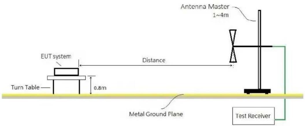
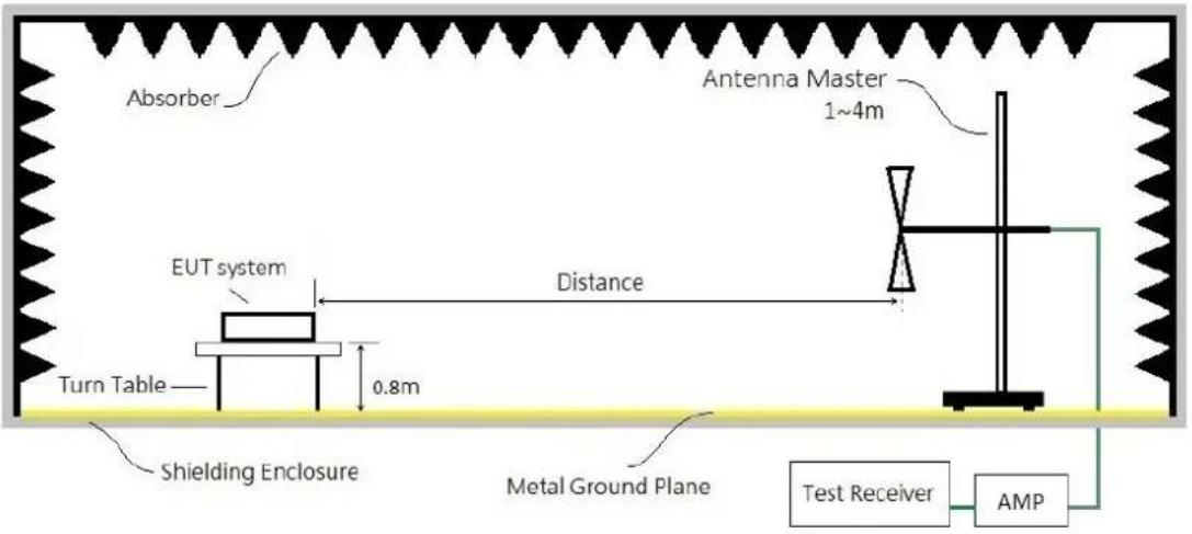
The EUT and test equipment were configured in accordance with the requirement of ANSI C63.4 2014 clause 5.4. and 5.5.
- For frequency range 30 to 1000MHz (at Open Area Test Site)
● For frequency range 30 to 1000MHz (at Semi Anechoic Chamber)
6.3. Radiation Emission Limits
- For Below 1GHz, FCC §15.109(a)(g)/CISPR 22
| Frequency Range (MHz) | Distance (meter) | Class A Limits Class B Limits | |
| Quasi-Peak [dB(μV/m)] | Quasi-Peak [dB(μV/m)] | ||
| 30 – 230 | 10 | 40 | 30 |
| 230 – 1000 47 37 | |||
| 30 – 230 | 3 | 50 | 40 |
| 230 – 1000 57 47 | |||
- For Above 1GHz, FCC §15.109(a)(g)/CISPR 22
| Frequency Range (MHz) | Distance (meter) | Class A Limits Class B Limits | |||
| Peak [dB(μV/m)] | Average [dB(μV/m)] | Peak [dB(μV/m)] | Average [dB(μV/m)] | ||
| Above 1000 3 79.54 59.54 | 73.98 | 53.98 | |||
- The tighter limit applies at the edge between two frequency bands.
- Distance refers to the distance in meters between the measuring instrument antenna and the closed point of any part of the E.U.T.
- The limits from 30 to 1000MHz are referred to CISPR 22 standard, which are in accordance with the requirement of FCC Part 15.38 (b)(3)、Part 15.109 (a)(g).
• The limits above 1GHz are referred to FCC Part 15.109(a)
- The EUT with open case was measured, the limit not exceed the radiated emission limits specified in Section 15.109 of this part by more than 6 dB.
● Required highest frequency for radiated measurement
| Highest frequency generated or used in the device or on which the device operates or tunes (MHz) | Upper frequency of measurement range (MHz) |
| Below 1.705 30 | |
| 1.705 – 108 1000 | |
| 108 – 500 2000 | |
| 500 – 1000 5000 | |
| Above 1000 | 5th harmonic of the highest frequency or 40 GHz, whichever is lower. |
6.4. Measurement Procedure
The radiated emission measurement was performed in accordance with the procedure of the ANSI C63.4-2014 clause 8.3.
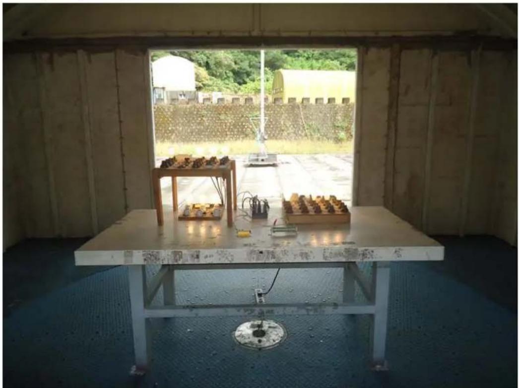
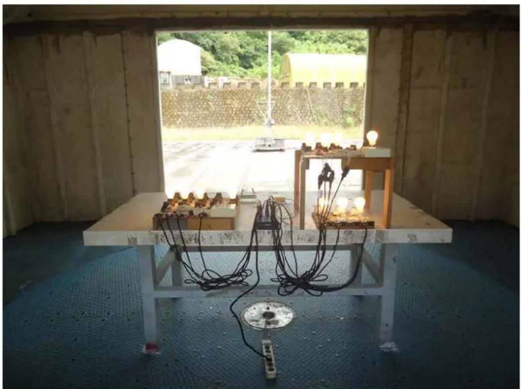
- The EUT and peripherals were placed on the rotatable non-conduction table, which is 0.8 meters above the ground reference plane at the semi anechoic chamber or OATS as described in section 4.1 and 6.2.
- The measurement distance is set as specified in section 6.3. The specified distance is between the horizontal projection onto the ground plane of the closest periphery of the EUT and the projection onto the ground plane of the center of the axis of the elements of the receiving antenna.
- The resolution bandwidth of the test receiver was at 120kHz (testing from 30 to 1000MHz) or 1MHz (testing above 1000MHz).
- Operate the EUT system as described in section 4.2.
- For the exploratory measurement, determine the highest emission amplitude relative to the limit on each of antenna polarization with the peak detector by each of the EUT operations over the specified frequency range and record it.
- For final measurement, select the EUT operation mode that produced the highest amplitude in the exploratory measurement to determine the highest emissions with each specified detector and record it.
- In order to determine the maximum emission level, must rotate the table in 360 degree and move the receiving antenna between 1\~4m height above the ground reference plane.
- In order to find the maximum emission, all of the interconnecting cables were manipulated, except for the bundled cable.
● Both polarizations of receiving antenna were determined.
● The measurement result was calculated by following formulas:
(30 - 1000MHz)
Emission Level (dBμV/m) = Reading (Receiver) (dBμV) + Cable Loss (dB) + Antenna Factor (dB/m)
(Above 1GHz)
Emission Level (dBμV/m) = Reading (Spectrum) (dBμV) + Cable Loss (dB) + Antenna Factor (dB/m) - Preamp Gain (dB)
- The 3dB bandwidth of the horn antenna is minimum 52 degree (or w = 2.93 m at 3m distance) for 1\~6 GHz.
6.5. Measurement Result
- For frequency range 30 – 1000MHz
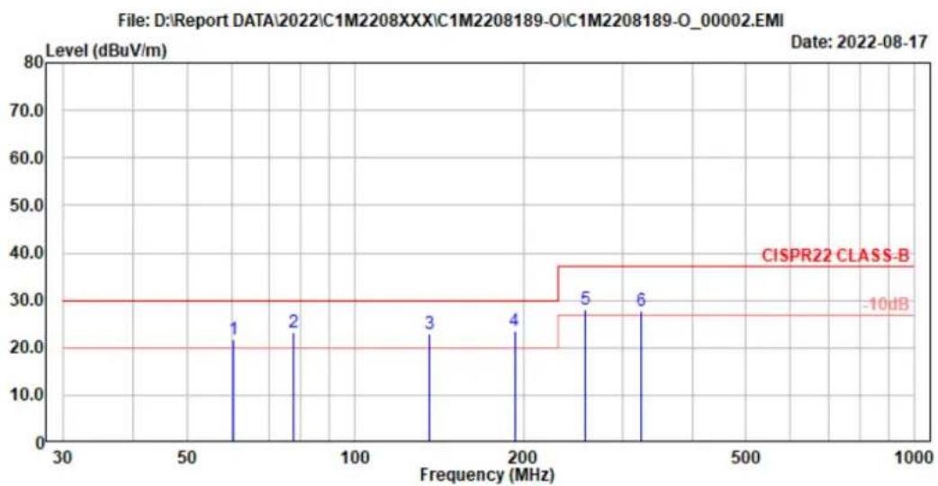
| Ant. Polarity Horizontal Test Result Pass | ||
| Test Mode Mode 1, Load With Lamp + R Load | ||
bar_line
| Frequency (MHz) | Level (dBuV/m) | | --------------- | -------------- | | 60 | 20 | | 80 | 25 | | 140 | 22 | | 190 | 24 | | 230 | 28 | | 300 | 28 | | 370 | 38 || Site No. | : No.6 Open Area Test Site | Data No. : 2 |
| Instrument 1 | : Receiver ESCS(337) | |
| Instrument 2 | : CBL6112B (818)|RE-07 | |
| Distance/Limit | : 10m /CISPR22 CLASS-B | Ant. Pol. : Horizontal |
| Environment | : 29*C/58% | Engineer : Eason Hsu |
| EUT Model | : P11U2 | Test Rating : 120Vac/60Hz |
| Test Mode | : Mode 1 |
| Freq. (MHz) | Ant. Factor (dB/m) | Cable Loss (dB) | Reading (dBμV) | Emission Level (dBμV/m) | Limits (dBμV/m) | Margin (dB) | Remark | |
| 1 | 60.528 | 12.91 | 1.08 | 7.61 | 21.60 | 30.00 | 8.40 | QP |
| 2 | 77.625 | 13.27 | 1.24 | 8.62 | 23.13 | 30.00 | 6.87 | QP |
| 3 | 135.628 | 17.60 | 1.74 | 3.61 | 22.95 | 30.00 | 7.05 | QP |
| 4 | 192.618 | 15.57 | 2.32 | 5.75 | 23.64 | 30.00 | 6.36 | QP |
| 5 | 257.628 | 18.86 | 2.51 | 6.85 | 28.22 | 37.00 | 8.78 | QP |
| 6 | 324.510 | 20.21 | 2.81 | 4.63 | 27.65 | 37.00 | 9.35 | QP |
Remarks: 1. Emission Level= Antenna Factor + Cable Loss + Reading. 2. The emissions not reported are 10 dB lower than the specified limit.
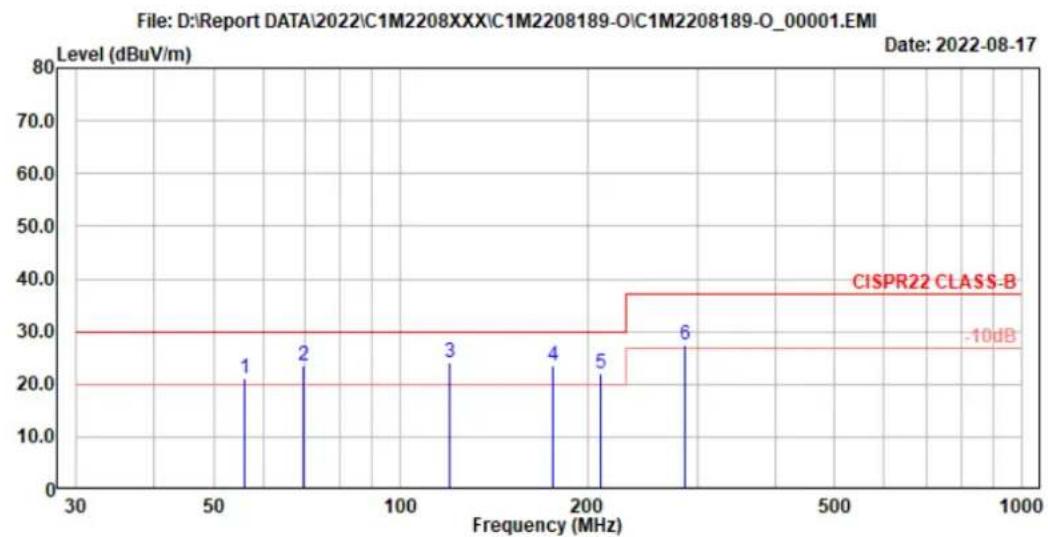
| Ant. Polarity Vertical Test Result Pass | ||
| Test Mode Mode 1, Load With Lamp + R Load | ||
bar_line
| Frequency (MHz) | Level (dBuV/m) | | --------------- | -------------- | | 50 | 1 | | 75 | 2 | | 125 | 3 | | 175 | 4 | | 200 | 5 | | 250 | 6 || Site No. | : No.6 Open Area Test Site | Data No. : 1 |
| Instrument 1 | : Receiver ESCS(337) | |
| Instrument 2 | : CBL6112B (818)|RE-07 | |
| Distance/Limit | : 10m /CISPR22 CLASS-B | Ant. Pol. : Vertical |
| Environment | : 29*C/58% | Engineer : Eason Hsu |
| EUT Model | : P11U2 | Test Rating : 120Vac/60Hz |
| Test Mode | : Mode 1 |
| Freq. (MHz) | Ant. Factor (dB/m) | Cable Loss (dB) | Reading (dBμV) | Emission Level (dBμV/m) | Limits (dBμV/m) | Margin (dB) | Remark | |
| 1 | 56.215 | 13.69 | 1.03 | 6.53 | 21.25 | 30.00 | 8.75 | QP |
| 2 | 69.528 | 12.96 | 1.16 | 9.44 | 23.56 | 30.00 | 6.44 | QP |
| 3 | 119.562 | 18.71 | 1.60 | 3.85 | 24.16 | 30.00 | 5.84 | QP |
| 4 | 176.251 | 15.89 | 2.18 | 5.63 | 23.70 | 30.00 | 6.30 | QP |
| 5 | 209.510 | 16.15 | 2.39 | 3.51 | 22.05 | 30.00 | 7.95 | QP |
| 6 | 286.510 | 19.29 | 2.63 | 5.53 | 27.45 | 37.00 | 9.55 | QP |
Remarks: 1. Emission Level= Antenna Factor + Cable Loss + Reading. 2. The emissions not reported are 10 dB lower than the specified limit.
7. Measurement Uncertainty List
The measurement uncertainty was estimated for test on the EUT according to CISPR 16-4-2. This uncertainty represents an expanded uncertainty expressed at approximately the 95% confidence level using a coverage of K=2.
The uncertainties value is not used in determining the PASS/FAIL results.
| Test Items/Facilities Frequency/Equipment/Unit Uncertainty | ||
| Conducted emissionsat AC mains power port | 9kHz-150kHz | ±3.7dB |
| 150kHz-30MHz | ±3.4dB | |
| Conducted emissions at wired network port 150kHz-30MHz | ±3.4dB | |
| Conducted emissions at broadcast receiver tuner port 150kHz-30MHz | ±3.4dB | |
| Conducted emissions Power Clamp(No. 7 Shielded Room) | 30MHz-300MHz | ±4.4dB |
| Conducted emissions Power Clamp(No. 8 Shielded Room) | 30MHz-300MHz | ±4.4dB |
| Radiated, magnetic field (Triple-Loop Antenna) 9kHz-30MHz | ±1.5dB | |
| Radiated, magnetic field (Loop Antenna) | 9kHz-150kHz | ±3.1dB |
| 150kHz-30MHz | ±3.0dB | |
| Radiated emissions(No.1 10m Semi Anechoic Chamber) | 30MHz-200MHz, 3m, Horizontal | ±4.5dB |
| 200MHz-1000MHz, 3m, Horizontal | ±4.1dB | |
| 30MHz-200MHz, 3m, Vertical | ±4.4dB | |
| 200MHz-1000MHz, 3m, Vertical | ±4.4dB | |
| 30MHz-200MHz, 10m, Horizontal | ±4.4dB | |
| 200MHz-1000MHz, 10m, Horizontal | ±3.9dB | |
| 30MHz-200MHz, 10m, Vertical | ±4.4dB | |
| 200MHz-1000MHz, 10m, Vertical | ±4.1dB | |
| 1GHz-6GHz, 3m | ±4.7dB | |
| 6GHz-18GHz, 3m | ±4.4dB | |
| Radiated emissions(No.2 10m Semi Anechoic Chamber) | 30MHz-200MHz, 3m, Horizontal | ±4.1dB |
| 200MHz-1000MHz, 3m, Horizontal | ±4.0dB | |
| 30MHz-200MHz, 3m, Vertical | ±4.5dB | |
| 200MHz-1000MHz, 3m, Vertical | ±4.4dB | |
| 30MHz-200MHz, 10m, Horizontal | ±4.1dB | |
| 200MHz-1000MHz, 10m, Horizontal | ±3.8dB | |
| 30MHz-200MHz, 10m, Vertical | ±4.4dB | |
| 200MHz-1000MHz, 10m, Vertical | ±4.2dB | |
| 1GHz-6GHz, 3m | ±4.8dB | |
| 6GHz-18GHz, 3m | ±4.4dB | |
| Radiated emissions(No.1 3m Semi Anechoic Chamber) | 30MHz-200MHz, 3m, Horizontal | ±3.8dB |
| 200MHz-1000MHz, 3m, Horizontal | ±4.1dB | |
| 30MHz-200MHz, 3m, Vertical | ±4.5dB | |
| 200MHz-1000MHz, 3m, Vertical | ±4.5dB | |
| 1GHz-6GHz, 3m | ±4.7dB | |
| 6GHz-18GHz, 3m | ±4.1dB | |
| Radiated emissions(No.2 3m Semi Anechoic Chamber) | 30MHz-200MHz, 3m, Horizontal | ±3.6dB |
| 200MHz-1000MHz, 3m, Horizontal | ±3.9dB | |
| 30MHz-200MHz, 3m, Vertical | ±4.1dB | |
| 200MHz-1000MHz, 3m, Vertical | ±4.6dB | |
| 1GHz-6GHz, 3m | ±4.8dB | |
| 6GHz-18GHz, 3m | ±4.2dB | |
| Radiated emissions(No.3 3m Semi Anechoic Chamber) | 30MHz-200MHz, 3m, Horizontal | ±3.9dB |
| 200MHz-1000MHz, 3m, Horizontal | ±4.2dB | |
| 30MHz-200MHz, 3m, Vertical | ±4.3dB | |
| 200MHz-1000MHz, 3m, Vertical | ±4.5dB | |
| Radiated emissions(No.4 3m Semi Anechoic Chamber) | 30MHz-200MHz, 3m, Horizontal | ±4.1dB |
| 200MHz-1000MHz, 3m, Horizontal | ±4.5dB | |
| 30MHz-200MHz, 3m, Vertical | ±4.4dB | |
| 200MHz-1000MHz, 3m, Vertical | ±4.8dB | |
| 1GHz-6GHz, 3m | ±5.0dB | |
| 6GHz-18GHz, 3m | ±4.7dB | |
| Radiated emissions(No.5 3m Semi Anechoic Chamber) | 30MHz-200MHz, 3m, Horizontal | ±4.2dB |
| 200MHz-1000MHz, 3m, Horizontal | ±4.3dB | |
| 30MHz-200MHz, 3m, Vertical | ±4.3dB | |
| 200MHz-1000MHz, 3m, Vertical | ±4.7dB | |
| 1GHz-6GHz, 3m | ±4.8dB | |
| 6GHz-18GHz, 3m | ±4.5dB | |
| Radiated emissions(No.6 Open Area Test Site) | 30MHz-200MHz, 3m, Horizontal | ±3.6dB |
| 200MHz-1000MHz, 3m, Horizontal | ±4.1dB | |
| 30MHz-200MHz, 3m, Vertical | ±3.6dB | |
| 200MHz-1000MHz, 3m, Vertical | ±4.1dB | |
| 30MHz-200MHz, 10m, Horizontal | ±3.6dB | |
| 200MHz-1000MHz, 10m, Horizontal | ±3.9dB | |
| 30MHz-200MHz, 10m, Vertical | ±3.6dB | |
| 200MHz-1000MHz, 10m, Vertical | ±3.9dB | |
| Radiated emissions(No.7 Open Area Test Site) | 30MHz-200MHz, 3m, Horizontal | ±4.0dB |
| 200MHz-1000MHz, 3m, Horizontal | ±4.3dB | |
| 30MHz-200MHz, 3m, Vertical | ±4.4dB | |
| 200MHz-1000MHz, 3m, Vertical | ±4.7dB | |
| 30MHz-200MHz, 10m, Horizontal | ±4.0dB | |
| 200MHz-1000MHz, 10m, Horizontal | ±4.2dB | |
| 30MHz-200MHz, 10m, Vertical | ±4.4dB | |
| 200MHz-1000MHz, 10m, Vertical | ±4.5dB | |
| Radiated emissions(No.8 Open Area Test Site) | 30MHz-200MHz, 3m, Horizontal | ±4.3dB |
| 200MHz-1000MHz, 3m, Horizontal | ±4.8dB | |
| 30MHz-200MHz, 3m, Vertical | ±4.5dB | |
| 200MHz-1000MHz, 3m, Vertical | ±4.8dB | |
| 30MHz-200MHz, 10m, Horizontal | ±4.3dB | |
| 200MHz-1000MHz, 10m, Horizontal | ±4.7dB | |
| 30MHz-200MHz, 10m, Vertical | ±4.5dB | |
| 200MHz-1000MHz, 10m, Vertical | ±4.6dB | |
8. Photographs
8.1. Powerline Conducted Emission Measurement
natural_image
Laboratory setup with two illuminated light bulbs on a wooden table, surrounded by wiring and equipment (no visible text or symbols)Front View of Conducted Measurement
natural_image
Interior view of a lab or workshop with a wooden table, equipment, and a central display unit (no visible text or symbols)Back View of Conducted Measurement
8.2. Radiated Emissions Measurement
- For Frequency Range 30 – 1000MHz
natural_image
Interior view of a workshop with a wooden table, test equipment, and a concrete structure under an arched window (no visible text or symbols)Front View of Radiated Measurement
natural_image
Interior view of a workshop with a wooden table, wires, and light bulbs, overlooking a large open window (no visible text or symbols)Back View of Radiated Measurement
APPENDIX
(Photos of EUT)
Figure 1
General Appearance (Front & Side View)
natural_image
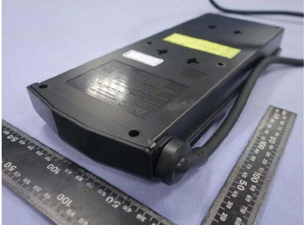
Black electrical power strip device placed next to a ruler for scale, no visible text or symbols on the device itself.Figure 2
General Appearance (Back & Side View)
natural_image
Black electronic device with attached cable and a yellow label, placed next to a ruler for scale (no visible text or symbols on the device itself)Figure 3
General Appearance (Top View)
natural_image
Black APC power strip device with multiple switches and a coiled cable, placed next to a ruler for scale (no visible text or symbols on device body)- Technical Compliance Statement FCC Test Report
- TEST REPORT
- Applicant for:
- Prepared by:
- EUT Description
- Table of Content
- Revision of Test Report
- Summary of Test Result
- Test Result
- Description of Test Firm
- General Information
- Description of Application
- Description of the EUT
- Highest Frequency within EUT
- Determination of Worse Case Operating Modes
- Final Test Configuration
- Measurement Arrangement
- Equipment and cables arrangement
- Method of Exercising EUT
- List of Supported Units under Test
- List of Used Cables under Test
- Measurement of Conducted Emissions
- List of Test Instruments
- Test Setup
- Power-line Conducted Emission Limits
- Measurement Procedure
- Measurement Result
- Measurement of Radiated Emissions
- List of Test Instruments
- Test Setup
- Radiation Emission Limits
- Measurement Procedure
- Measurement Result
- Measurement Uncertainty List
- Photographs
- Radiated Emissions Measurement
- APPENDIX
- (Photos of EUT)
Brand : APC
Model : SurgeArrest
Category : Surge protector