
DIN-CENCN-2-POE - Wi-Fi repeater Crestron - Free user manual and instructions
Find the device manual for free DIN-CENCN-2-POE Crestron in PDF.


| Product Type | Wi-Fi Repeater |
| Brand | Crestron |
| Model | DIN-CENCN-2-POE |
| Mounting Type | DIN Rail |
| Power Source | Power over Ethernet (PoE) |
| Wi-Fi Standards | 802.11 a/b/g/n/ac |
| Frequency Bands | 2.4 GHz, 5 GHz |
| Maximum Data Rate | 1200 Mbps (combined) |
| Number of Ethernet Ports | 2 (1 PoE in, 1 LAN) |
| Dimensions (HxWxD) | 4.5 x 3.5 x 1.5 inches (114 x 89 x 38 mm) |
| Weight | 0.5 lbs (225 g) |
| Operating Temperature | 32°F to 104°F (0°C to 40°C) |
| Maximum Coverage Area | 2000 sq ft (per repeater) |
| Maximum Number of Connected Devices | 50 |
| Security Encryption | WPA2, WPA3 |
| LED Indicators | Power, Network, Signal Strength |
| Configuration Interface | Web browser (built-in web server) |
| Management | Crestron Fusion, SNMP, Telnet, SSH |
| RoHS Compliant | Yes |
| Certifications | CE, FCC, UL |
| Included Accessories | DIN rail clip, quick start guide |
| Warranty | 3 years limited |
Frequently Asked Questions - DIN-CENCN-2-POE Crestron
User questions about DIN-CENCN-2-POE Crestron
0 question about this device. Answer the ones you know or ask your own.
Ask a new question about this device
Download the instructions for your Wi-Fi repeater in PDF format for free! Find your manual DIN-CENCN-2-POE - Crestron and take your electronic device back in hand. On this page are published all the documents necessary for the use of your device. DIN-CENCN-2-POE by Crestron.
USER MANUAL DIN-CENCN-2-POE Crestron
Crestron Electronics, Inc.
Original Instructions
The U.S. English version of this document is the original instructions. All other languages are a translation of the original instructions.
Crestron product development software is licensed to Crestron dealers and Crestron Service Providers (CSPs) under a limited nonexclusive, nontransferable Software Development Tools License Agreement. Crestron product operating system software is licensed to Crestron dealers, CSPs, and end-users under a separate End-User License Agreement. Both of these Agreements can be found on the Crestron website at www.crestron.com/legal/software_license_agreement.
The product warranty can be found at www.crestron.com/warranty.
The specific patents that cover Crestron products are listed at www.crestron.com/legal/patents.
Certain Crestron products contain open source software. For specific information, visit www.crestron.com/opensource.
Crestron, the Crestron logo, 4-Series, Cresnet, Crestron Home, and Crestron Toolbox are either trademarks or registered trademarks of Crestron Electronics, Inc. in the United States and/or other countries. Other trademarks, registered trademarks, and trade names may be used in this document to refer to either the entities claiming the marks and names or their products. Crestron disclaims any proprietary interest in the marks and names of others. Crestron is not responsible for errors in typography or photography.
©2022 Crestron Electronics, Inc.
Contents
Overview .1.
Cresnet Device Definitions 2
Control Systems.2
Cresnet Servers..2
Cresnet Clients..2.
Network Architecture 3
Maximum Network Size..3
Network Topologies..3.
Home-Run Topology..3
Daisy-Chain Topology..3
Star-Network Topology..4
Cresnet ID Assignment..4.
Client Device Distribution 6
Cresnet Distribution Blocks..6.
Cresnet Distribution Block 6
Multitype Cresnet Distribution Block 7
DIN Rail Cresnet Distribution Block 8
Cresnet Hubs....9
Cresnet Hub 9
Din Rail Cresnet Hub 10
Ethernet-to-Cresnet Bridging
Ethernet-to-Cresnet Bridge with PoE 11
Ethernet-to-Cresnet Bridge for CAEN Automation Enclosures 12
Wiring and Connectors
Overview 14
Supported Cresnet Cables 15
Non-Plenum Cables 15
Plenum-Rated Cables 16
High-Power Cables 16
Data-Only Cables 17
Terminate Cresnet Wiring to a Connector 17
Best Practices 18
Power Requirements
Cresnet Power Calculator 20
Calculate Power Requirements for Wire Runs 21
Wire Gauge Overview..21.
Resistance Equation Formula.21
Example Scenarios.22
External Power Supplies 23
Appendix A: Troubleshoot Cresnet IDs. 24.
Insufficient Power.24
Incorrect Wire Gauge.24
Incorrect Wiring 24
Poor Wiring..25
Excessive Cresnet Clients.25
Overview
The Cresnet ^™ communications protocol is designed for Crestron devices that do not require the higher speeds of Ethernet. Cresnet provides a dependable and flexible wiring solution, allowing multiple devices to be wired together in parallel using various network topologies. A single Cresnet server can provide power and data to up to 25 client devices. Cresnet networks can be further expanded using Cresnet hubs and Ethernet-to-Cresnet bridges.
This design guide provides the following information that can be referenced when designing a Cresnet network system:
- Overview of Cresnet server and client devices
• Overview of Cresnet architecture
• Cresnet device distribution options - Ethernet-to-Cresnet bridging options
• Cresnet wiring and connector options and best practices
• Cresnet power considerations
• Common troubleshooting scenarios
Cresnet Device Definitions
A Cresnet network consists of three primary device categories: control systems, Cresnet servers (masters) and Cresnet clients (slaves).
Control Systems
A control system supplies data to a combination of Cresnet clients, Cresnet distribution blocks, or Cresnet hubs via its NET (Cresnet) port. Ethernet-to-Cresnet bridges can be added to a Crestron control system to expand the size of the Cresnet network, creating isolated Cresnet subnets that each behave as a Cresnet server with its own unique address space.
Certain Crestron control systems and Ethernet-to-Cresnet bridges also supply 24VDC power to Cresnet clients.
Cresnet Servers
A Cresnet server is a connection to a control system that allows a control system program to communicate with Cresnet clients. A Cresnet server supplies power and data to Cresnet clients via its built-in Cresnet bus. The Cresnet bus distributes bidirectional data communication and 24VDC power to each wired client device over a single 4-conductor cable.
Cresnet Clients
A Cresnet client receives its power and data from a Cresnet server either directly (wired to the Cresnet server) or indirectly (wired to a Cresnet distribution block or hub or daisy-chained to another Cresnet client). Cresnet clients each have their own specific power draw requirements that must be taken into consideration when designing the Cresnet network.
Examples of Cresnet clients include keypads, lighting controls, shade motors, thermostats, and occupancy sensors.
Network Architecture
The following sections provide information about the Cresnet network architecture that should be taken into consideration when designing a Cresnet network.
Maximum Network Size
The maximum size of a Cresnet network is dependent on the system design:
- A single Cresnet server supports up to 25 client devices with a maximum aggregate cable length of 1,500 ft (457 m).
- A Cresnet network can be expanded to contain up to 90 client devices using Cresnet hubs. Cresnet hubs also allow for longer cable runs. For more information, refer to Cresnet Hubs (on page 9).
- A Cresnet network can be further expanded to contain over 90 client devices using Ethernet-to-Cresnet bridges. For more information, refer to Ethernet-to-Cresnet Bridging (on page 11).
Network Topologies
Cresnet network systems can be designed using any of the following network topologies. A topology should be chosen that best suits the needs of the particular Cresnet installation or space.
Home-Run Topology
For home-run topologies, wiring is run from the Cresnet server to a single Cresnet client. A distribution block is typically used in home-run topologies to allow the Cresnet server to provide power and data to multiple Cresnet clients from one central location in the room. For more information, refer to Cresnet Distribution Blocks (on page 6).
Daisy-Chain Topology
For daisy-chain topologies, wiring is run from the Cresnet server to a Cresnet client. For subsequent Cresnet clients, wiring is either run from a second port on the prior Cresnet client, or wires are doubled in the connector. This daisy chain can continue for up to 25 client devices or a for total run of 1,500 ft (457 m).
Star-Network Topology
For star-network topologies, wiring is run from the Cresnet server to a Cresnet hub. Cresnet clients are then branched off from the central hub. This topology is commonly used when a Cresnet wiring run needs to be taken into a different room. A distribution block connected to the hub can then be used to route power and data to Cresnet clients in the room. Several Cresnet hubs can be used to distribute power and data to multiple distribution blocks that all branch off from a single Cresnet server.
CAUTION: When designing a Cresnet network using the star-network topology, the design must ensure that no loops are created within the system. All runs from the Cresnet server must connect to Cresnet clients or hubs only. A wiring run must never return to the Cresnet server.
Cresnet ID Assignment
Cresnet IDs (NET IDs) are unique identifiers given to Cresnet devices on a network (similar to IP IDs) that allow for network communication between Cresnet clients and servers. NET IDs should be assigned using the Network Device Tree View tool in Crestron Toolbox™ software. For more information, refer to the Crestron Toolbox help file.
Some devices ship with default Cresnet IDs other than 03 or 01 to help streamline some packaged systems or to facilitate adjustments by certain software wizard systems. For a partial list of default Cresnet IDs, refer to Crestron Online Help article 1001590.
NOTE: Cresnet servers always have a NET ID of 02. Valid NET IDs for Cresnet clients are 03 through FE (03 through 254 decimal).
Refer to the following best practices when assigning NET IDs:
- Ensure no duplicate NET IDs are assigned to Cresnet clients on a Cresnet network. Using the Network Device Tree View tool in Crestron Toolbox software to assign NET IDs is recommended to avoid duplicate IDs.
- No more than 90 client devices should be present on a Cresnet network.
- Crestron recommends grouping NET IDs so that similar products on a Cresnet network are grouped together within a NET ID range. The following example shows how various product types could be grouped using NET IDs:
NOTE: Grouping Cresnet IDs helps organizations to group Cresnet devices to align with various organizational standards. There are no electrical or communication advantages to grouping Cresnet IDs.
• Thermostats: 10 through 1F
- Keypads: 20 through 4F
- Touch screens: 50 through 6F
- Lighting controls: 70 through 9F
- Other products: AO through BF
Client Device Distribution
A Cresnet network system with a single Cresnet server can provide power and data to up to 25 client devices with a maximum cumulative wiring run of 1,500 ft (457 m). Cresnet networks can be expanded via Cresnet distribution blocks and Cresnet hubs. Each device type and supported models are described in the following sections.
Cresnet Distribution Blocks
Cresnet distribution blocks allow for multiple Cresnet wiring runs to be terminated to one central location within a room. The Cresnet distribution block is connected to the Cresnet server and distributes power and data from the server to all connected clients. Cresnet distribution blocks are commonly used in home-run network topologies, but can also be used to power client devices off of a central Cresnet hub.
The following Cresnet distribution blocks are available.
Cresnet Distribution Block
The CNTBLOCK is a parallel distribution block designed to facilitate the termination of multiple Cresnet wiring runs in an equipment cabinet, closet, or beneath a table.
CNTBLOCK Cresnet Distribution Block
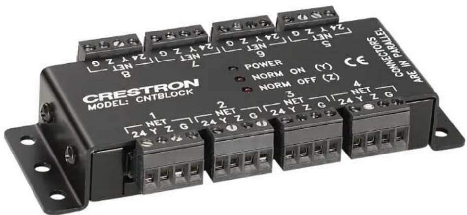
- Diagnostic LEDs indicate the presence of network power and data.
- Eight 4-pin detachable black (5 mm) terminal blocks are provided, grouped in two sets of four.
- Power can be isolated between the two sets by removing an internal jumper.
- Includes an integral mounting flange for mounting to a flat surface.
Multitype Cresnet Distribution Block
The C2N-HBLOCK is a parallel distribution block for the termination of multiple Cresnet cables. Three different types of connectors are provided to accommodate all types of Cresnet wiring, including standard 4-wire Cresnet cable, Cresnet High-Power (HP) cable, and RJ-11 modular cables (legacy installations only).
C2N-HBLOCK Multitype Cresnet Distribution Block
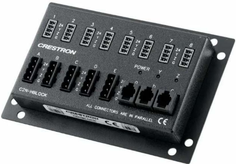
- Diagnostic LEDs indicate the presence of network power and data.
- Up to three units may be rack mounted together using the optional CNXRMAK rack mount kit (sold separately).
- Includes an integral mounting flange for mounting to a flat surface.
CAUTION: Do not connect or daisy chain more than one power input (power pack or power supply) to the C2N-HBLOCK. Connecting multiple power inputs may cause damage to the power inputs.
DIN Rail Cresnet Distribution Block
The DIN-BLOCK is a DIN rail-mounted Cresnet distribution block designed to facilitate the termination of Cresnet wiring at a head end or distribution point. DIN rail mounting enables modular installation alongside Crestron DIN Rail lighting and automation control modules and other third-party DIN rail mountable devices.
DIN-BLOCK DIN Rail Cresnet Distribution Block
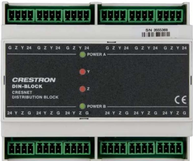
- Diagnostic LEDs indicate the presence of network power and data.
- Twelve 4-pin detachable green (3.5 mm) terminal blocks are provided, grouped in two sets of six.
- Provides a split power bus for flexible 24V power distribution.
Cresnet Hubs
Cresnet hubs are designed to expand the size of a Cresnet network system to over 25 client devices or 1,500 ft (457 m) of wire runs. Each Cresnet hub provides multiple isolated Cresnet segments that each support an additional 25 client devices and 1,500 ft (457 m) of wire runs. Multiple Cresnet hubs can be added to a Cresnet network system to allow for up to 90 powered client devices. Cresnet hubs are used primarily within star-network network topologies where a single Cresnet server must power client devices across multiple rooms or locations in a facility.
Cresnet Hub
The CNXHUB is a six-segment Cresnet hub designed for configuring large Cresnet networks. A Cresnet hub is ordinarily required for any Cresnet network that has more than 25 devices or 1,500 ft (457 m) of cable.
CNXHUB Cresnet Hub
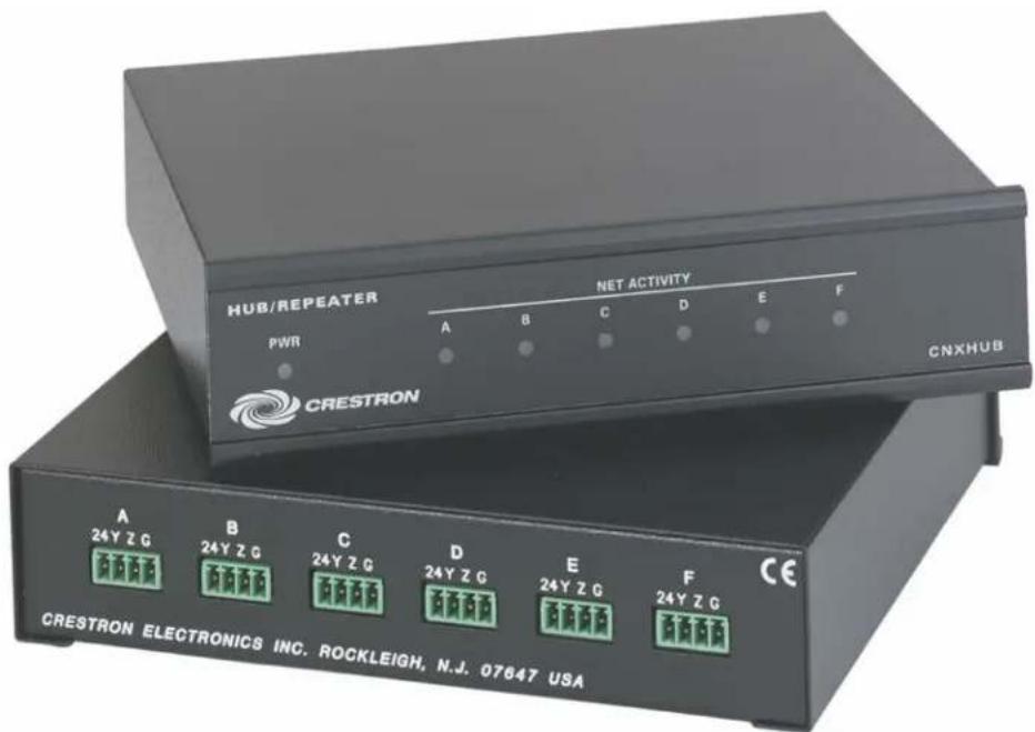
• Diagnostic LEDs indicate the presence of network activity for connected devices.
- Features six isolated Cresnet segments, each capable of supporting another 25 devices with an additional aggregate run of 1,500 ft (457 m) of cable. More hubs can be added to allow for a network of up to 90 devices.
- Housed in a compact metal enclosure that can be placed on a shelf, attached under a table, or mounted in a 19 in. equipment rack. Its 1 RU half-width form factor allows it to fit in a single rack-space alongside a second CNXHUB or other 1 RU half-width Crestron device.
Din Rail Cresnet Hub
The DIN-HUB is a DIN rail-mounted Cresnet hub designed for configuring large Cresnet networks. DIN rail mounting enables modular installation alongside Crestron DIN Rail lighting and automation control modules and other third-party DIN rail mountable devices.
DIN-HUB DIN Rail Cresnet Hub
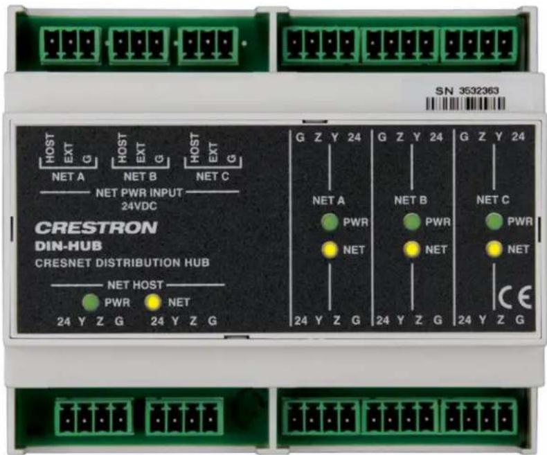
- Diagnostic LEDs indicate the presence of network activity for connected devices.
- Features three isolated Cresnet segments, each capable of supporting another 25 devices with an additional aggregate run of 1,500 ft (457 m) of cable. More hubs can be added to allow for a network of up to 90 devices.
• Each isolated segment supports up to 75 W of power to secondary devices.
Ethernet-to-Cresnet Bridging
Adding one or more Ethernet-to-Cresnet bridges to a Cresnet server distributes Cresnet over high-speed Ethernet and allows for system sizes of over 90 Cresnet clients. The increased bandwidth of Ethernet reduces latency for overall improved speed and performance. By leveraging existing LAN infrastructure in a facility, wiring distances can be extended easily while potentially reducing the overall wiring requirements. One or more bridges can be deployed on a single Cresnet client, and they can be addressed by more than one control system.
The following Ethernet-to-Cresnet bridge devices are supported for expanding the size of a Cresnet network over Ethernet.
Ethernet-to-Cresnet Bridge with PoE
The DIN-CENCN-2-POE works with any Cresnet server to maximize the reliability of a Cresnet network. It offers a more robust solution than a Cresnet block or hub, providing two isolated subnets and built-in diagnostics, plus versatile power distribution options and a convenient DIN rail form factor.
NOTE: Crestron also provides a DIN-CENCN-2 Ethernet-to-Cresnet bridge that does not supply any power over PoE or PoE+.
DIN-CENCN-2-POE Ethernet-to-Cresnet Bridge with PoE
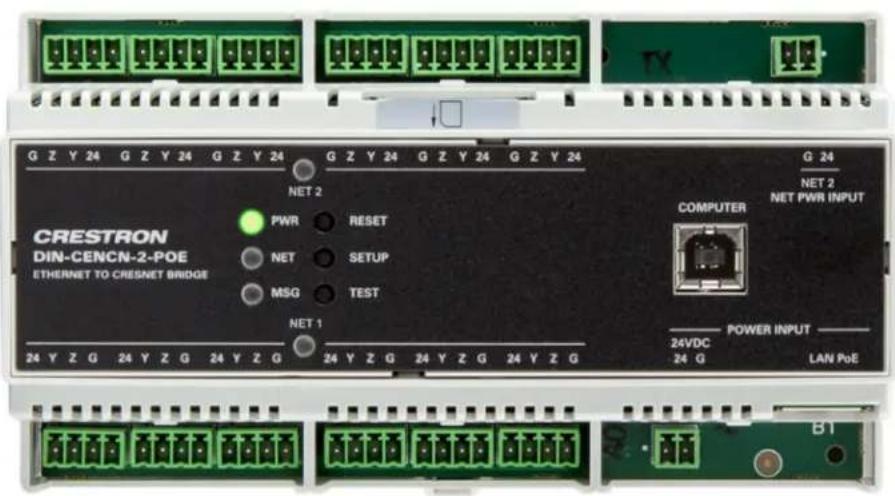
- Features two isolated Cresnet subnets that each behave as a Cresnet server with its own unique address space. Each subnet is capable of supporting 25 devices and provides six connectors for terminating multiple wiring runs.
- Offers versatile power options:
° 10 W of power provided by PoE (Power over Ethernet) to both subnets, with up to 20 W of power provided by PoE+.
- 75 W of power provided by external power supplies to one or both subnets depending on the configuration.
- Diagnostic tools address many common Cresnet issues caused by wiring faults, insufficient power, or too many client devices.
- Provides a TEST button on the front panel that can be pressed to generate error codes on the LED indicators. Complete details for each error code can be viewed in a web browser or via Crestron Toolbox™ software.
Ethernet-to-Cresnet Bridge for CAEN Automation Enclosures
The CAEN-BLOCK-CENCN-2-POE works with any Cresnet server to maximize the reliability of a Cresnet network. The bridge can be mounted at the bottom of a CAEN, CAEN-MLO, or CAENIB enclosure to provide a high-speed Ethernet interface between the enclosure and one or more outboard Cresnet servers. It includes Cresnet and override connectivity for the CLX series lighting control modules within the enclosure, and adds a separate isolated Cresnet subnet for outboard Cresnet keypads, thermostats, sensors, and other Cresnet clients. It also allows those Cresnet clients to be powered using a PoE, PoE+, or a 24VDC power source.
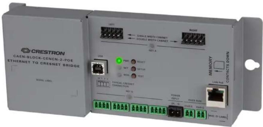
- Features two isolated Cresnet subnets that each behave as a Cresnet server with its own unique address space. Each subnet is capable of supporting 25 devices and provides six connectors for terminating multiple wiring runs.
-
Offers versatile power options:
-
10 W of power provided by PoE (Power over Ethernet) to both subnets, with up to 20 W of power provided by PoE+.
° 75 W of power provided by external power supplies to one or both subnets depending on the configuration.
- Diagnostic tools address many common Cresnet issues caused by wiring faults, insufficient power, or too many client devices.
- Provides a TEST button on the front panel that can be pressed to generate error codes on the LED indicators. Complete details for each error code can be viewed in a web browser or via Crestron Toolbox™ software.
Wiring and Connectors
The following sections provide information about Cresnet wiring and connectors within a Cresnet network system.
NOTE: To view and download drawing packages that show common Cresnet wiring scenarios, refer to Crestron Online Help article 1001565.
Overview
Observe the following about Cresnet wiring and connectors:
- All wire is calculated in American Wire Gauge (AWG) sizes
- All network wire must consist of two twisted pairs and a drain wire:
° One twisted pair of 24VDC power and ground (GND) conductors
One twisted pair of Y and Z data conductors wrapped in a foil shield
° One stranded jacketless conductor (for drain wire)
- Standard Cresnet wire uses the following specifications:
- 18 AWG (0.82 mm ^2 ) red/black twisted pair is used for 24VDC power and ground.
22 AWG (0.33 mm ^2 ) blue/white twisted pair is used for data (Y and Z) with aluminum/polyester foil shield (providing 100% coverage) - 24 AWG (0.20 mm ^2 ) stranded tinned copper drain wire
• High-Powered (HP) Cresnet wire uses the following specifications:
- 12 AWG (3.31 mm ^2 ) red/black twisted pair is used for 24VDC power and ground.
° 22 AWG (0.33 mm ^2 ) blue/white twisted pair is used for data (Y and Z) with aluminum/polyester foil shield (providing 100% coverage) - 24 AWG (0.20 mm ^2 ) stranded tinned copper drain wire
- Cresnet cables are rated for low-voltage (60VAC/VDC or less) applications.
CAUTION: Cresnet cables should never be used within high-voltage (60VAC/VDC or more) applications.
- The following connectors are used by Cresnet-supported devices. Each connector type supports wire termination for Cresnet power, data, and ground.
- Black 4-pin terminal blocks with 5 mm spacing
- Green 4-pin terminal blocks with 3.5 mm spacing
- RJ-11 style Cresnet distribution ports (legacy installations only)
Supported Cresnet Cables
The following Crestron cable types are supported for Cresnet wiring runs. Cables types should be selected based on the Cresnet network installation requirements.
NOTE: For more information on determining the correct wire gauge to use for Cresnet installations, refer to Calculate Power Requirements for Wire Runs (on page 21).
Crestron Cresnet cables are compliant with the following regulatory standards:
- NEC Article 800
- UL® Subject 13, Type CM
- CSA Type CMG
- RoHS
Non-Plenum Cables
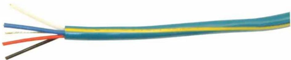
CRESNET-NP series cables are recommended for most standard Cresnet wiring runs. CRESNET-NP series cables contain one 18 AWG pair for 24VDC and ground and one 22 AWG shielded twisted pair for control data within a non-plenum PVC jacket.
CRESNET-NP Series Cable
natural_image
Coiled electrical cable with colored wires (blue, yellow, red, black) showing different conductor orientations (no text or symbols visible)• CRESNET-NP-BK-B500: Cresnet Control Cable, Non-Plenum, Black, 500 ft (152 m) box
• CRESNET-NP-OR-B500: Cresnet Control Cable, Non-Plenum, Orange, 500 ft (152 m) box
• CRESNET-NP-TL-B250: Cresnet Control Cable, Non-Plenum, Teal, 250 ft (76 m) box
• CRESNET-NP-TL-B500: Cresnet Control Cable, Non-Plenum, Teal, 500 ft (152 m) box
• CRESNET-NP-TL-SP500: Cresnet Control Cable, Non-Plenum, Teal, 500 ft (152 m) spool
• CRESNET-NP-TL-SP1000: Cresnet Control Cable, Non-Plenum, Teal, 1,000 ft (304 m) spool
• CRESNET-NP-WH-B500: Cresnet Control Cable, Non-Plenum, White, 500 ft (152 m) box
Plenum-Rated Cables
CRESNET-P series cables are recommended for wiring runs within plenum spaces (such as air ducts) or applications that require plenum-rated materials. CRESNET-P series cables contain one 18 AWG pair for 24VDC and ground and one 22 AWG shielded twisted pair for control data within a plenum-rated polymer jacket.
CRESNET-P Series Cable

natural_image
Close-up of a multicolored cable with exposed wires and insulation (no text or symbols visible)• CRESNET-P-BK-SP500: Cresnet Control Cable, Plenum-Rated, Black, 500 ft (152 m) spool
• CRESNET-P-OR-SP500: Cresnet Control Cable, Plenum-Rated, Orange, 500 ft (152 m) spool
• CRESNET-P-TL-SP500: Cresnet Control Cable, Plenum-Rated, Teal, 500 ft (152 m) spool
• CRESNET-P-TL-SP1000: Cresnet Control Cable, Plenum-Rated, Teal, 1,000 ft (304 m) spool
High-Power Cables
CRESNET-HP series cables feature extra-large conductors for power and ground to support devices that draw a large amount of power over a Cresnet bus. CRESNET-HP series cables contain one 12 AWG pair for 24VDC and ground and one 22 AWG shielded twisted pair for control data within a non-plenum PVC jacket.
CRESNET-HP Series Cable

natural_image
Cross-sectional illustration of a multi-core cable with colored bands (no text or symbols)• CRESNET-HP-NP-TL-SP500: Cresnet High-Power Control Cable, Non-Plenum, Teal, 500 ft (152 m) spool
- CRESNET-HP-NP-TL-SP1000: Cresnet High-Power Control Cable, Non-Plenum, Teal, 1,000 ft (304 m) spool
Data-Only Cables
CRESNET-DM series cables are designed specifically for applications where a Cresnet device only will receive data (and not power). CRESNET-DM series cables contain one 22 AWG shielded twisted pair for control data within a non-plenum PVC jacket.
CRESNET-DM Series Cable

natural_image
Cross-sectional illustration of a multi-core cable with visible insulation and insulation sheathing (no text or symbols)- CRESNET-DM-NP-SP500: Cresnet Control Cable, Data Only, Non-Plenum, 500 ft (152 m) spool
Terminate Cresnet Wiring to a Connector
To terminate Cresnet wiring to a connector on a Cresnet device:
-
Remove the outer PVC jacket from the Cresnet cable.
-
For a single-wire Cresnet to terminal block connection, remove approximately 1.25 in. (3.18 cm).
-
For a dual-wire Cresnet to terminal block connection, remove approximately 1.50 in. (3.81 cm).
-
Remove the aluminum/polyester shield from the outside of the exposed blue and white twisted pair wires.
NOTE: Trim the shield only to the PVC outer jacket of the exposed wire pair.
-
Determine the treatment of the drain wire.
-
The drain wire is only used on the source or power supply end. It is trimmed and can be removed from the Cresnet network device end.
- When the drain wire is used, it must be added to the black (ground) wire prior to termination. To do so, twist the drain with the bare copper of the black wire, trim both wires to the same length, then tin the end of the twisted bare wire.
-
Apply heat shrink to the drain wire prior to termination.
-
Note the number of twists available on the blue and white wires. This number should be kept when terminating into a connector to maintain data integrity.
-
Remove the foam polyolefin insulation from the blue and white wires with a wire stripping tool that supports 22 AWG (0.33 mm ^2 ). The copper stranded twisted wire is exposed.
-
For termination with green (3.5 mm) terminal blocks, remove approximately 1/4 in. (7 mm) of insulation.
-
For termination with black (5 mm) terminal blocks, remove approximately 9/32 in. (7.5 mm) of insulation.
-
Twist the copper strands on the individual blue and white wires. Do not twist the two wires together.
NOTE: Twist the copper strands on each wire immediately before inserting the blue and white wires into the connector. This helps to ensure that there are no loose strands that could touch another connection.
-
On the connector, raise the cage clamps using the appropriate screwdriver as described below.
-
Green (3.5 mm) terminal blocks use slotted screws with M2 screw heads. Use a slotted screwdriver with a width of 9/64 in. (3.5 mm).
-
Black (5 mm) terminal blocks use slotted screws with M3 screw heads. Use a slotted screwdriver with a width of 7/32 in. (5.5 mm).
-
Insert each wire into the appropriate slot on the connector that matches pin out on the device's NET port. Typically, this is done in the following order: red (24VDC), white (Y data), blue (Z data), and black (ground, with or without twisted drain wire).
NOTE: Ensure the correct number of twists are used when terminating the white and blue wires as described in step 4.
-
Secure the wires down to the connector by tightening down the cage clamp as described below.
-
For green (3.5 mm) terminal blocks, tighten the cage clamp to 4.4–5.3 in-lb (0.5–0.6 N-m).
- For black (5 mm) terminal blocks, tighten the cage clamp to 3.5–4.4 in-lb (0.4–0.5 N-m).
Best Practices
The following best practices should be followed when wiring a Cresnet network system.
CAUTION: While Cresnet devices can help to diagnose some wiring issues, certain miswirings can cause damage to the Cresnet primary device or remote network devices. Ensure all wiring best practices are followed as described below.
- Crestron recommends using only Crestron certified wire and cables for Cresnet installation projects. For more information on supported Crestron cable types, refer to Supported Cresnet Cables (on page 15).
NOTE: If Crestron certified wire and cable is not used and technical onsite support is required to troubleshoot an issue caused by improper wiring, a support charge may be incurred.
- To maintain data integrity, Cresnet cable lengths should not exceed 1,500 ft (457 m) per run.
- While not mandatory, Crestron recommends placing service loops within Cresnet wiring runs for future accessibility.
- When daisy chaining network units, always twist the ends of the incoming wire and outgoing wire that share a pin on the network connector.
Do not twist the white and blue wires together. Only twist the copper strands on the end of each individual wire.
The compression connector requires the strands of each wire to compress down to hold the wire correctly during temperature changes.
- Observe the following when grounding the data twisted pair drain wire:
- Stranded drain wire is connected at the power supply end only.
- Foil shield can be removed at both ends.
- When terminating multiple wires into a green (3.5 mm) terminal block:
° Never use more than one 18 AWG (0.82 m) or one 12 AWG (3.31 m) wires in the same pin connection.
- Never use more than two 22 AWG (0.33 m) wires in the same pin connection.
- When terminating multiple wires into a black (5 mm) terminal block:
° Never use more than two 18 AWG (0.82 mm) or one 12 AWG (3.31 mm) wires in the same pin connection.
- Never use more than two 22 AWG (0.33 m) wires in the same pin connection.
• Following termination:
- Ensure that each cable and its corresponding wire strands are not frayed or touching any other connection on the connector.
- Copper wire should be barely visible.
- Wires should not be able to be removed from the connector when applying 5 N (or less) of force.
° Heat shrink can be used to cover the PVC jacket transition to the four wires to allow for additional strain relief. - Labels should be applied to match any applicable drawings or labeling practices used within the Cresnet installation.
Power Requirements
A Cresnet network system must be designed to handle the total power that will be required by all Cresnet clients on the network. Power requirements vary based on the number of Cresnet clients in a system, the power draw for each Cresnet client, wire run lengths from a power source, and the wire gauge used. Insufficient power is a common cause of Cresnet network issues, so it is important to ensure your network design addresses all power requirements.
The following sections explain how to calculate and troubleshoot power requirements for your Cresnet network system.
Cresnet Power Calculator
The Cresnet Power Calculator is a tool that allows integrators to easily calculate the total power draw for all Cresnet clients connected to a given leg of the Cresnet network. The Cresnet Power Calculator also calculates the total power available from Cresnet servers and power supplies, allowing integrators to determine whether the provided device combination will result in a power surplus or deficit.
Cresnet Power Calculator
Support / Tools / Calculators / Cresnet Power Calculator
Need to know how much power your control system application will require? Simply enter the quantities of each Cresnet device in the list below that you have specified for your project. If you do not find a specific product listed below, it most likely doesn't consume any power from the Cresnet network.
To determine wiring distance considerations, including minimum wire gauge required for your installation, please refer to Online Help Answer ID 1629.
Power Suppliers
| Model Number | Description | Quantity | Power (watts) |
| AADS | Adagio® Audio Distribution System w/Dual AM/FM Tuners | 1 | 20 |
| AADSI | Adagio® Audio Distribution System w/Dual AM/FM Tuners - International Version, 230V | 1 | 20 |
| AADS-XM | Adagio® Audio Distribution System with AM/FM & XM® Satellite Radio Tuners | 0 | 20 |
| AAE | Adagio® Audio Expander | 0 | 50 |
| AAEI | Adagio® Audio Expander - International Version, 230V | 0 | 50 |
Estimated Usage
| 40.00 WattsSURPLUS POWER |
| Print ResultsClear Results |
To use the Cresnet Power Calculator:
-
Open www.crestron.com/Support/Tools/Calculators/Cresnet-Power-Calculator in a web browser.
-
Under Power Suppliers, enter the quantity of the desired Cresnet servers and power supplies within their applicable table rows.
- Under Power Consumers, enter the quantity of the desired Cresnet clients within their applicable table rows.
The Estimated Usage column on the right of the screen updates dynamically to show the current power surplus or deficit value based on the selected device quantities.
- Select Print Results to print a summary of the selected devices and estimated power usage.
- Select Clear Results to clear all quantity values entered within the calculator.
Calculate Power Requirements for Wire Runs
The correct wire gauge must be selected to ensure that a wiring run can supply sufficient power to the Cresnet clients on a particular network leg. The length of the wiring run and power draw of the Cresnet client(s) must also be considered.
Wire Gauge Overview
The black and red twisted pair (24VDC power and ground) is used for powering Cresnet clients. Therefore, only the wire gauge for this twisted pair is required when calculating power requirements for wire runs.
The blue and white twisted pair (Y and Z data) does not factor into Cresnet power calculations. Data distances are independent of power requirements and are calculated using 22 AWG (0.33 mm ^4 ) with a maximum run of 1,500 ft (457 m) per Cresnet server. Data wires are a twisted pair with foil shield, helping to reduce noise and interference.
Resistance Equation Formula
The following formula is used to calculate the correct wire gauge required for a particular leg of a Cresnet wiring run. The formula can also be rewritten to solve for other variables (such as length of wiring run).
Resistance Equation: R < 40,000 / (L x PF)
- R = Resistance value, in ohms (refer to the following table)
- L = Length of wiring run (or chain), in feet, from the power source or supply
- PF = Cresnet power factor of the entire wiring run (or chain) for all Cresnet client devices
The R (resistance) value correlates with a wire gauge as shown in the following table. Therefore, using the equation above, the selected wire gauge must correlate with a resistance value that is less than the value derived from 40,000 / (L x PF).
Resistance Value to Wire Gauge Comparison Table
| Resistance (R) Value Wire Gauge | |
| 1.6 Ω 12 AWG (3.31 mm) | ^2) - Cresnet High-Power |
| 6 Ω 18 AWG (0.82 mm) | ^2) - Cresnet Standard Power |
Example Scenarios
The following example scenarios show how the resistance equation can be used to solve for different variables within a Cresnet wiring run.
Example Scenario #1: Calculate Wire Gauge
This scenario explains how to calculate the wire gauge needed for powering one GLS-ODT-C-CN occupancy sensor (requiring 1.5 W) that is 1,500 ft (457 mm) away from its power source.
Use the resistance formula to calculate the resistance value of the wire run, where 1,500 is the value for L (length of wiring run) and 1.5 is the value for PF (Cresnet power factor):
$$ \begin{array}{l} R < 4 0, 0 0 0 / (1, 5 0 0 \times 1. 5) \ \cdot R < 1 7. 8 \ \end{array} $$
Next, use the table above to compare the resistance value of the wiring run with the resistance value of the Cresnet wires. For this scenario, any wire gauge with a resistance value less than 17.8 can be used to supply power to the GLS-ODT-C-CN.
Example Scenario #2: Calculate Wire Run Length
This scenario explains how to calculate the maximum distance that twelve SSC-102-EL room occupancy hallway signs (requiring 2.4 W each for a total of 28.8 W) can be placed from a client control system using 12 AWG (3.31m ^2 )wire.
Rewrite the resistance formula to solve for L, where 1.6 is the value for R (resistance value correlating with the wire AWG) and 28.8 is the value for PF (Cresnet power factor):
$$ \begin{array}{l} \cdot L < 4 0, 0 0 0 / (1. 6 \times 2 8. 8) \ \cdot L < 8 6 8 \ \end{array} $$
For this scenario, the maximum length of wiring that can be run to the SCC-102-EL devices from the power source is 868 ft (265 m).
NOTE: if using standard power Cresnet wire (18 AWG), the maximum length of wiring would be 231 ft (70 m), as derived from L < 40,000 / (6 x 28.8).
External Power Supplies
A Cresnet server supports cumulative wire runs up to 1,500 ft (457 m). However, due to voltage loss over longer distances, the internal Cresnet power supply in the Cresnet server may not provide enough power for longer wire runs.
In these scenarios, adding external power supplies (CNPWS-75 and C2N-SPWS300) ensure that enough power is provided across longer wire runs. The Cresnet cable runs from the Cresnet server to the power supply using only three of its four wires (Y data, Z data, and ground; 24VDC is not connected). Another Cresnet cable is run from the power supply to the Cresnet client with all four wires connected.
NOTE: To determine the wire gauge required for a wiring run between power supply and Cresnet client, only calculate the distance between the power supply and Cresnet client. The wiring run between the Cresnet server and power supply is not included in this calculation. For more information, refer to Resistance Equation Formula (on page 21).
If a Cresnet network needs to be expanded beyond 1,500 ft (457 m), a Cresnet hub or Ethernet-to-Cresnet bridge is required.
Appendix A: Troubleshoot Cresnet IDs
Occasionally, a Cresnet client may change its Cresnet ID within the Cresnet network if it has received data with corrupt data packets over the connected Y and Z data wires.
To determine whether a Cresnet client is receiving corrupt data packets, use the Network Analyzer tool in Crestron Toolbox software as described in the Crestron Toolbox help file to determine the error(s). The following sections describe common ways in which data packets may get corrupted.
Insufficient Power
Insufficient power is the most common cause for corrupt data packets. As Cresnet systems become increasingly complex, integrators must ensure that enough power is supplied for all Cresnet clients in the system. For more information on power requirements, refer to Power Requirements (on page 20).
- Use the Cresnet Power Calculator (on page 20) to determine the total power requirements for all client devices on a given leg of the Cresnet network. The total power requirements must not exceed the power supplied by Crestron servers or external power supplies on that leg.
- If using a C2N-SPWS300 (300 W) power supply, ensure that each segment does not draw more than 75 W and that the total power draw across the power supply does not exceed 300 W.
- If using a CNPWS-75 (75 W) power supply, ensure that the total power draw across the power supply (for all devices connected to the 24VDC connector) does not exceed 75 W.
- For control systems, the internal power supply provides additional power for Cresnet devices that are wired directly to the control system's 24VDC connector. For more information on the power supplied by a particular control system model, refer to its product page at www.crestron.com.
Incorrect Wire Gauge
When selecting a wire gauge (in AWG) that will be used to supply power to a Cresnet client, the wire gauge resistance value must not exceed the resistance value required by the client device on the network. For more information on calculating the correct wire gauge, refer to Calculate Power Requirements for Wire Runs (on page 21).
Incorrect Wiring
Typically, incorrect wiring only occurs when wiring is used in a Cresnet network that is not Crestron certified (such as CAT5e cable). For an overview on Cresnet wiring requirements and supported Cresnet cables, refer to Wiring and Connectors (on page 14).
NOTE: Cresnet Y and Z data must use one twisted pair. Using one twisted pair for Cresnet Y and another twisted pair for Cresnet Z can cause too much resistance.
Poor Wiring
All wired connections should be checked to ensure that all wiring has been properly stripped and terminated to the connector.
- Many network issues are caused by loose wire strands that can short another pin or missing wire strands.
- If any loose or missing wire strands are discovered, redress the connection. Also, ensure that all screws on the terminal block are tightened down to the wires.
Excessive Cresnet Clients
No more than 25 Cresnet clients can be powered by a single Cresnet server. If more than 25 Cresnet clients are required, use a Cresnet hub or Ethernet-to-Cresnet bridge to add additional devices to the Cresnet network.

- Original Instructions
- Contents
- Overview .1.
- Cresnet Device Definitions 2
- Network Architecture 3
- Client Device Distribution 6
- Ethernet-to-Cresnet Bridging
- Wiring and Connectors
- Power Requirements
- Overview
- Cresnet Device Definitions
- Control Systems
- Cresnet Servers
- Cresnet Clients
- Network Architecture
- Maximum Network Size
- Network Topologies
- Home-Run Topology
- Daisy-Chain Topology
- Star-Network Topology
- Cresnet ID Assignment
- Client Device Distribution
- Cresnet Distribution Blocks
- Cresnet Distribution Block
- Multitype Cresnet Distribution Block
- DIN Rail Cresnet Distribution Block
- Cresnet Hubs
- Cresnet Hub
- Din Rail Cresnet Hub
- Ethernet-to-Cresnet Bridge with PoE
- Ethernet-to-Cresnet Bridge for CAEN Automation Enclosures
- Supported Cresnet Cables
- Non-Plenum Cables
- Plenum-Rated Cables
- High-Power Cables
- Data-Only Cables
- Terminate Cresnet Wiring to a Connector
- Best Practices
- Cresnet Power Calculator
- Calculate Power Requirements for Wire Runs
- Wire Gauge Overview
- Resistance Equation Formula
- Example Scenarios
- Example Scenario #1: Calculate Wire Gauge
- Example Scenario #2: Calculate Wire Run Length
- External Power Supplies
- Appendix A: Troubleshoot Cresnet IDs
- Insufficient Power
- Incorrect Wire Gauge
- Incorrect Wiring
- Poor Wiring
- Excessive Cresnet Clients
Brand : Crestron
Model : DIN-CENCN-2-POE
Category : Wi-Fi repeater