
FAN73B7C-BL - Antenna Furrion - Free user manual and instructions
Find the device manual for free FAN73B7C-BL Furrion in PDF.


| Product Type | TV/AM/FM/LTE Rooftop Antenna with Ceiling Mount Bracket |
| Model | FAN73B7C-BL (also FAN73B7C-BL2, FAN73B7C-BL3) |
| Brand | Furrion |
| Operating Voltage | 9-16 Vdc, 12 Vdc typical |
| Current Consumption | <100 mA @ 12V |
| TV Frequency Range (UHF) | 470-700 MHz |
| TV Gain (UHF) | 28 dB max |
| TV Noise Figure (UHF) | <6 dB |
| TV Frequency Range (VHF/FM) | 47-230 MHz |
| TV Gain (VHF/FM) | 20/24 dB max |
| TV Noise Figure (VHF/FM) | <7 dB |
| AM Frequency Range | 520-1710 kHz |
| FM Frequency Range | 87.5-108 MHz |
| FM Antenna Gain | 15 dB max |
| FM Noise Figure | <7 dB |
| Impedance | 75 ohm |
| Radiation Pattern | Omni-directional |
| Weather Resistance | UV resistant, waterproof housing |
| Mounting | Rooftop with included ceiling mount bracket |
| Compatibility | HDTV (DVB-T, ISDB-T, DTMB, ATSC), FM/AM radio |
| Connector Type | F-connectors |
| Weight (approx.) | 2.6 lbs (1.18 kg) |
| Included Accessories | TV antenna wing, antenna base, ceiling mount bracket, screws, warranty card, instruction manual |
| Warranty | 1 year |
Frequently Asked Questions - FAN73B7C-BL Furrion
User questions about FAN73B7C-BL Furrion
0 question about this device. Answer the ones you know or ask your own.
Ask a new question about this device
Download the instructions for your Antenna in PDF format for free! Find your manual FAN73B7C-BL - Furrion and take your electronic device back in hand. On this page are published all the documents necessary for the use of your device. FAN73B7C-BL by Furrion.
USER MANUAL FAN73B7C-BL Furrion
TV/AM/FM/LTE ROOFTOP ANTENNA WITH CEILING MOUNT BRACKET
Instruction Manual

natural_image
Technical line drawing of a mechanical component with a base and top, alongside a labeled panel (no text or symbols on the diagram itself)Ceiling Mount Bracket
Model:FAN73B7C-BL
FAN73B7C-BL2
FAN73B7C-BL3
Welcome
Thank you for purchasing this Furrion® TV/AM/FM/LTE Rooftop Antenna with ceiling mount bracket. Before operating your new product, please read these instructions carefully. This instruction manual contains information for safe use, installation and maintenance of the product.
Please keep this instruction manual in a safe place for future reference. This will ensure safe use and reduce the risk of injury. Be sure to pass on this manual to new owners of this product.
The manufacturer does not accept responsibility for any damages due to not observing these instructions.
If you have any further questions regarding our products, please contact us at support@furrion.com
Supplier's Declaration of Conformity
47 CFR § 2.1077 Compliance Information
Unique Identifier
Trade Name: Furrion
Model No.: FAN73B7C-BL, FAN73B7C-BL2, FAN73B7C-BL3
Responsible Party – U.S. Contact Information
Furrion Innovation Center & Institute of Technology
52567 Independence Ct., Elkhart, IN 46514, USA
Toll free:1-888-354-5792; Email: support@furrion.com
FCC Compliance Statement
This device complies with Part 15 of the FCC Rules. Operation is subject to the following two conditions: (1) This device may not cause harmful interference, and (2) this device must accept any interference received, including interference that may cause undesired operation.
Industry Canada Statement
This Class B digital apparatus complies with Canadian ICES-003.
CAN ICES-3 (B)/NMB-3(B)
Contents
Welcome....1
Contents ....3
Product Overview ....4
Product Features....4
Installation ....5
What's in the Box 5
Mounting the Antenna....5
Installing the Ceiling Mount Bracket 8
Mounting the Wall Plate....9
Connections....10
Wiring Diagram 10
Testing the Power Supply....10
Operation....11
Running a Channel Scan....11
Selecting TV Antenna Reception....11
Selecting Cable TV 11
Specifications 12
Product Overview
Product Features
- Compatible with HDTV of various digital terrestrial signals (DVB-T, ISDB-T, DTMB, ATSC), stereo and FM/AM radios.*
- The waterproof housing is UV resistant, and is designed for superior durability using injection mold.
- Omni directional antennas receive VHF, UHF, FM and AM signal from every point regardless of the direction you are traveling.
• Built-in high gain and low noise amplifier. - The antenna is surface-treated to withstand impact from all weather conditions.
- SMT Technology and micro-electronics ensure excellent antenna performance.
Installation
Do not install couplers, splitters, etc. between the power supply and the antenna. Installation of any item on the downlead may cause a short in the system. The downlead supplies +12VDC to the preamp in the antenna. The power supply should be turned OFF when connecting or disconnecting cables to the power supply and antenna, but should be turned ON during voltage testing.
What's in the Box
Make sure you have the following items included in the packaging. If any items are damaged or missing, contact your dealer.
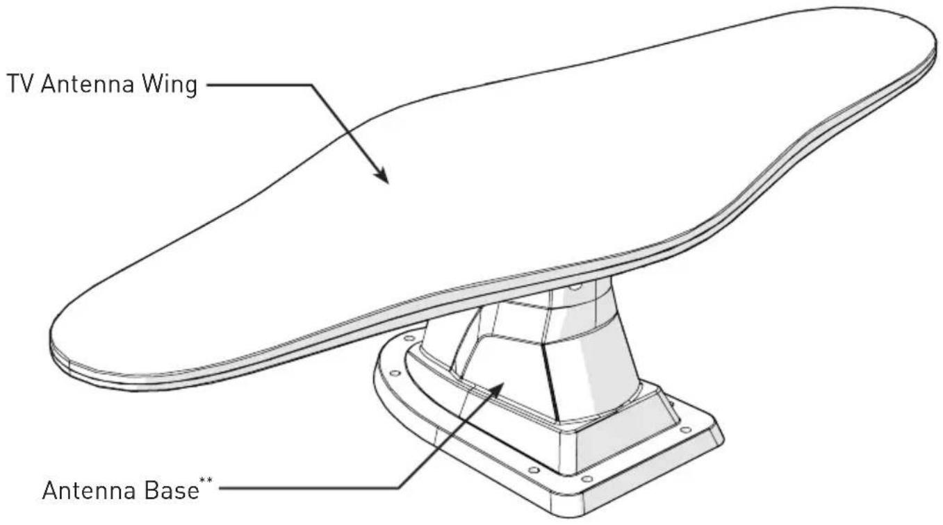
• TV Antenna Wing x 1
- Antenna Base x 1
• Ceiling mount bracket x 1
- 4 x 12 mm square socket pan head tapping screws x 2
- Warranty Card x 1
• Instruction Manual x 1
Mounting the Antenna
There are two ways of installing the rooftop antenna:
- Method 1 - Making a new opening. In this case the ceiling of the RV must be accessible.
- Method 2 - Using the existing opening in the vehicle roof.
Making a New Opening
- Select a flat location where there is sufficient area to mount and seal the antenna to the roof surface. Do not install the antenna next to any other device on the rooftop.
- Mark a basic hole outline on the RV rooftop using the antenna base as a template. (Fig. 1)*

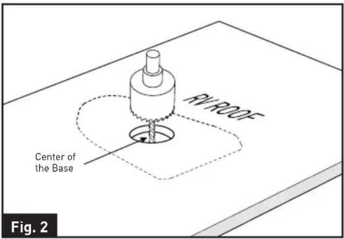
- Drill a 2" (50mm) circle hole in the RV roof using a hole saw. (Fig. 2)**
Installation
- Thread the cables of the LTE antenna base through the opening. Put the LTE antenna base over the opening area. (Fig. 3)
NOTE: Make sure the center hole of the LTE antenna is aligned with the hole in the RV roof.

- Fix the LTE antenna base on the RV roof using seven stainless steel self-tapping screws and tighten using a screwdriver. (Fig. 4) ^***
NOTE: Do not overtighten as damage to the base may occur, which will void the warranty. A screw angle up to 30 degrees is acceptable without damaging the base.

natural_image
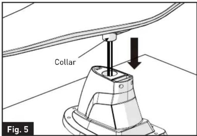
3D technical diagram of a mechanical component with mounting holes and alignment markers (no text or symbols)- Insert the bottom collar of the TV antenna wing into the center hole of the LTE antenna base. (Fig. 5) Make sure the rubber seal on top of the LTE antenna base is in location.
- Fix the TV antenna wing in the LTE antenna base using the two 4 x 12mm square socket pan head tapping screws provided with the product. (Fig. 6)

natural_image
Technical line drawing of a mechanical component with mounting flange and support structure (no text or symbols)- Apply a liberal amount of sealant around the antenna base and the screw holes to prevent water leakage if necessary. Check with the RV manufacturer for the standard sealant for the vehicle. (Fig. 7)
Installation

natural_image
Technical diagram showing a mechanical assembly with a base and tool, labeled 'Fig. 7' (no text or symbols on the diagram itself)- Follow the wiring guidelines below to connect the cables of TV/FM antenna (black) and FM/AM antenna (white) from the interior of the RV ceiling. See "Wiring Diagram" section for detail.
- TV/FM antenna (Black) with extension cable to DC powered wall-plate.
- FM/AM antenna (White) to audio system.
Using the Existing Opening
- Unscrew and remove the old TV antenna from the RV rooftop.
- Remove all caulking compound around the opening.
- Insert the bottom collar of the TV antenna wing into the center hole of the antenna base.
NOTE: Make sure the rubber seal on top of the LTE antenna base is in location. (Fig. 8)

- Fix the TV antenna wing in the base using the two 4 x 12mm square socket pan head tapping screws provided with the product. (Fig. 9)

natural_image
Technical line drawing of a mechanical component with curved and flanged features, labeled Fig. 9 (no text or symbols on the diagram itself)-
Following the guidelines below to connect the cables of TV/FM antenna (black) and FM/AM antenna (white) from the interior of the RV ceiling. See "Wiring Diagram" section for detail.
-
TV/FM antenna (Black) with extension cable to DC powered wall-plate.
-
FM/AM antenna (White) to audio system.
-
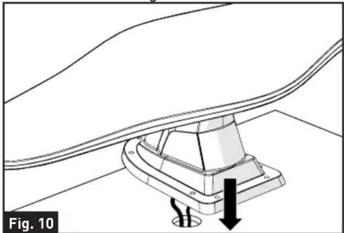
Thread the cables of the antenna base through the opening. (Fig. 10) NOTE: Make sure the middle circle of the LTE antenna is center aligned
Installation
with the cutting hole in the RV roof.
natural_image
Technical diagram of a mechanical assembly with a base mount and directional arrow, labeled Fig. 10 (no text or symbols on the diagram itself)- Fix the antenna base on the RV roof using seven stainless steel self-tapping screws and tighten using a screwdriver. (Fig. 11)***
NOTE: Do not overtighten as damage to the base may be occur, which will void the warranty. A screw angle up to 30 degrees is acceptable without damaging the base.

natural_image
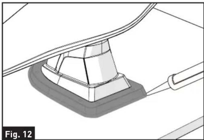
Technical line drawing of a boat hull with support structures and vertical supports (no text or symbols)- Apply a liberal amount of sealant around the antenna base and the screw holes to prevent water leakage if necessary. Check with the RV manufacturer for the standard sealant for the vehicle. (Fig. 12)
natural_image
Technical diagram of a mechanical component with a base and connecting rod, labeled Fig. 12 (no text or symbols on the diagram itself)Installing the Ceiling Mount Bracket
NOTE: It is recommended that you have all the wires connected before permanently installing the ceiling mount bracket onto the rooftop. See 'Wiring Diagram' section on how to connect the wires.
- Push to remove the top cover of the ceiling mount bracket. (Fig. 13)

- Follow the wiring guidelines below to connect the cables from the interior of the RV ceiling. See "Wiring Diagram" section for detail. Fix the wires with nylon cable tie. (Fig. 14)
Installation
- LTE Antennas: Connect to the rooftop unit by mapping the same wire color.
- Power Wires: Connect to the RV +12Vdc (current rating >1A) power source. Red is power wire, Black is ground wire.
- Network Wires: Connect to the network interface in the RV.

- Cover the base of the ceiling mount bracket over the cutout area and secure with eight stainless steel self-tapping screws (not supplied). (Fig. 15)

natural_image
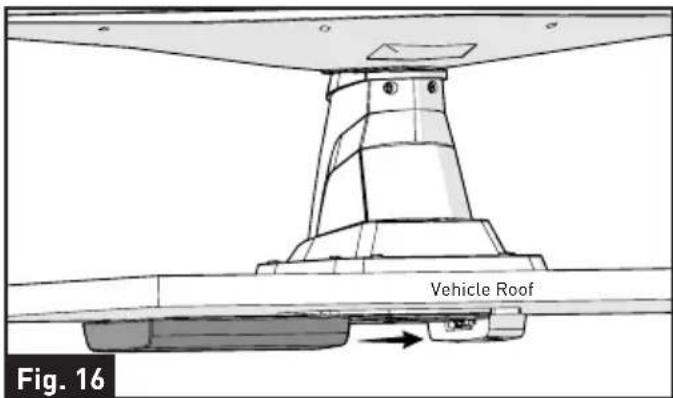
Technical diagram of a vehicle roof assembly with supporting components (no text or symbols)- Place back the top cover to the ceiling mount bracket. (Fig. 16)
Mounting the Wall Plate
The wall plate may be flush-mounted in most standard electrical boxes.
- Select a suitable location that is not susceptible to moisture.
- Mark and cut a hole in the RV wall.
- Connect the antenna cables to the wall plate. See 'Wiring Diagram' for detail info.
- Fix the wall plate in the wall using 2 stainless steel self-tapping screws (not included).
NOTE: The wall plate is sold separately, please contact the dealer for detail.
Connections
Wiring Diagram
Refer to accessories page for planning connections.
WARNING: The wall plate should be turned off while connecting cables.
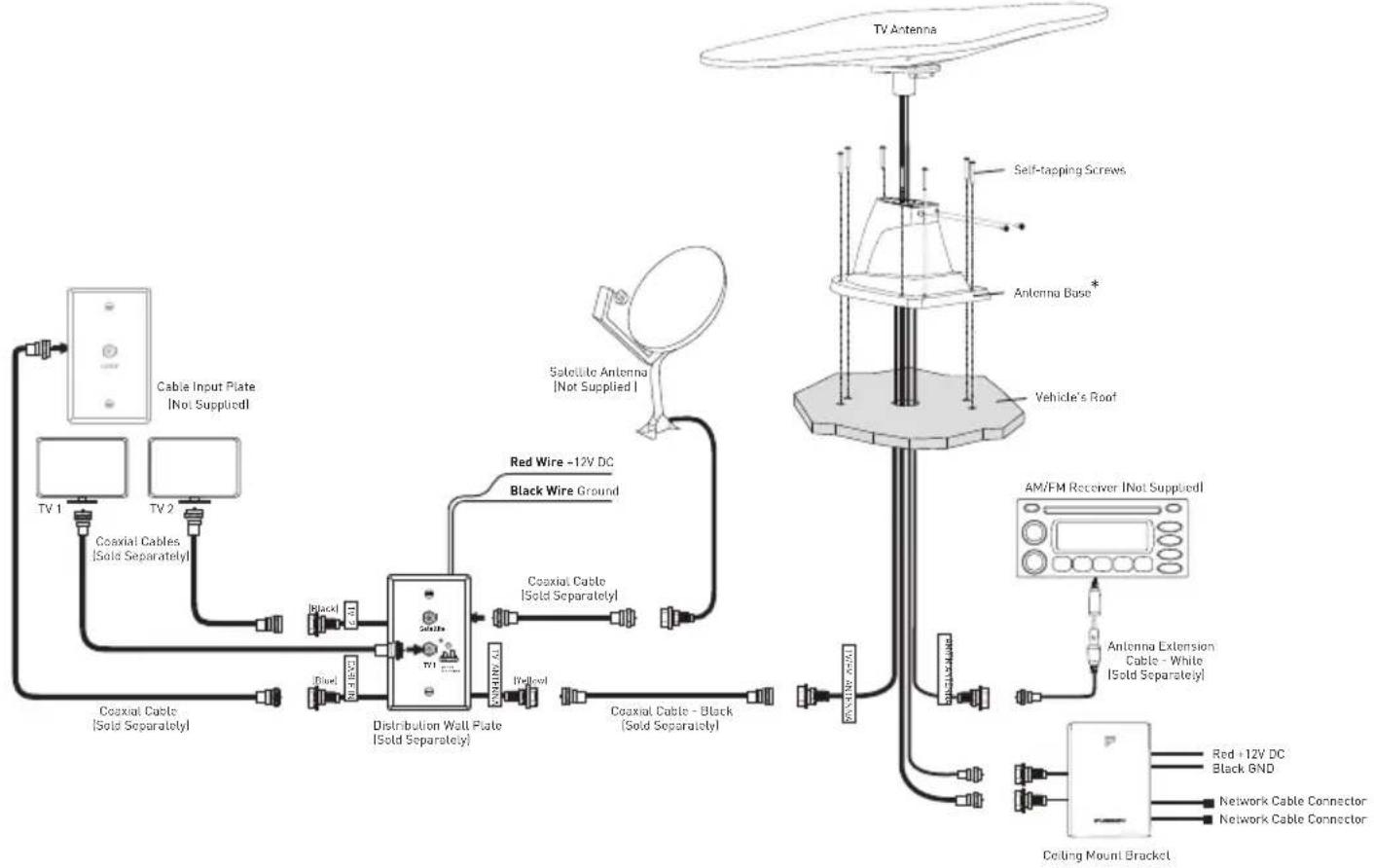
Connect the cables from the antenna to distribution wall plate and to the FM radio (AM Radio needs to connect the FM/AM antenna from the rooftop unit). Connect the power cables from the distribution wall plate according to the diagram below.
flowchart
graph TD
    A["Cable Input Plate (Not Supplied)"] --> B["TV 1"]
    A --> C["TV 2"]
    B --> D["Coaxial Cable (Sold Separately)"]
    C --> E["Coaxial Cable (Sold Separately)"]
    D --> F["Distribution Wall Plate (Sold Separately)"]
    E --> G["Distribution Wall Plate (Sold Separately)"]
    F --> H["Red Wire -12V DC Black Wire Ground"]
    G --> I["Red Wire -12V DC Black Wire Ground"]
    H --> J["Vehicle's Roof"]
    I --> K["Vehicle's Roof"]
    J --> L["AM/FM Receiver (Not Supplied)"]
    K --> M["Antenna Extension Cable - White (Sold Separately)"]
    L --> N["Coiling Mount Bracket"]
    M --> O["Coaxial Cable - Black (Sold Separately)"]
    N --> P["Coaxial Cable - Black (Sold Separately)"]
    O --> Q["Radio Cable"]
    P --> R["Radio Cable"]
    Q --> S["Satellite Antenna (Not Supplied)"]
    R --> T["Satellite Antenna (Not Supplied)"]
    S --> U["Satellite Antenna (Not Supplied)"]
    T --> V["Self-tapping Screws"]
    U --> W["Antenna Base*"]
    V --> X["Red +12V DC Black GND"]
    W --> Y["Network Cable Connector"]
    X --> Z["Network Cable Connector"]
Testing the Power Supply
Make sure your TV set is working properly.
- Disconnect the cable from the antenna jack on the power supply and check for +12VDC. If +12VDC is present, there is a cable problem connecting the power supply to the antenna, repair/replace the cable. If +12VDC is not present at the antenna jack, be sure the indicator light is ON. If not, check the polarity of the red/white wires and the +12VDC source.
Operation
Running a Channel Scan
To receive maximum number of channels, a channel scan is required once the antenna and power supply have been correctly installed and all cables have been properly connected. A new scan might find any new channels that have been added in your area or find any channels that have been changed or moved since the last scan.
NOTE: Antenna reception may vary based on transmitting antenna tower height, lobe pattern of the transmitter, height of the receiving antenna, weather conditions and terrain on receiving path, including trees, buildings and hills. The steps to perform a channel scan may vary between televisions or compatible devices. Always run a channel scan in the following situations:
- Anytime the antenna is moved or enters a new region
• Anytime a channel is lost.
Selecting TV Antenna Reception
To receive TV antenna reception, press the ON/OFF switch and the power indicator will be lit.*

Selecting Cable TV
NOTE: The vehicle must be connected to an external cable source.
To receive cable TV, press the ON/OFF switch and the power indicator will be turned off.**

Specifications
| Technical Specification | |||
| MODEL FAN73B7C-BL | FAN73B7C-BL2FAN73B7C-BL3 | ||
| OPERATING CONDITION | |||
| VOLTAGE 9-16Vdc, 12Vdc typical | |||
| CURRENT CONSUMPTION <100mA @ 12V | |||
| AM/FM ANTENNA | |||
| AM FUNCTION | Frequency Range 520kHz to 1710kHz | ||
| Radiation Direction Omni - direction | |||
| FM FUNCTION | Antenna Gain 15dB Max 10dB Max | ||
| Max. output level 106dBμV | |||
| Frequency Range 87.5MHz - 108MHz | |||
| Radiation Direction Omni - direction | |||
| Impedance 75ohm | |||
| Noise Figure <7dB <11dB | |||
| TV ANTENNA | |||
| UHF FUNCTION | Antenna Gain 28dB Max | ||
| Max. output level 105dBμV | |||
| Frequency Range 470MHz to 700MHz | |||
| Radiation Direction Omni - direction | |||
| Impedance 75ohm | |||
| Noise Figure <6dB | |||
| FM / VHF FUNCTION | Antenna Gain 20dB/24 dB Max 15dB Max | ||
| Max. output level 106dBμV | |||
| Frequency Range 47MHz - 230MHz | |||
| Radiation Direction Omni - direction | |||
| Impedance 75ohm | |||
| Noise Figure <7dB <11dB | |||
FURRION
Furrion Innovation Center & Institute of Technology
● 52567 Independence Ct., Elkhart, IN 46514, USA ● Toll free: 1-800-789-3341
- Email: support@furrion.com
©2007-2020 Furrion Ltd. Furrion® and the Furrion logo are trademarks licensed for use by Furrion Ltd. and registered in the U.S. and other countries.
Patents pending (FAN73B7C-BL)
FURRION.COM
FURRION ACCESS
OMNI-DIRECTIONAL ROOFTOP ANTENNA
WITH CEILING MOUNT BRACKET
FAN73B7C


360° SIGNAL RECEPTION

2 TIMES STRONGER
SIGNAL STRENGTH

UV RESISTANT

WATERPROOF

2 x 2 GB
ETHERNET
(OPTIONAL)

HD TV
COMPATIBLE

AM & FM SIGNAL

DUAL 4G ANTENNAS OPTIMIZE RECEPTION

AERODYNAMIC DESIGN

LIGHTWEIGHT (only 2.6 lbs)
- Omni-directional antenna receives VHF, UHF, FM, AM and LTE signal from every point regardless of the direction you are traveling in
- The antenna is surface-treated to withstand severe weather conditions with durable ASA material
• Built-in high gain low noise amplifier for minimum interference
• SMD technology and micro-electronics ensure excellent performance
- Compatible with HDTVs of various digital terrestrial signals (DVB-T, ISDB-T, DTMB, ATSC) and DAB/FM radios
FAN73B7C | OMNI-DIRECTIONAL ROOFTOP ANTENNA WITH CEILING MOUNT BRACKET
Omni-directional Rooftop Antenna Ceiling Mount Bracket

Specifications - AM/FM Antenna (FAN73A70-BL/PS)
| AM Function | |
| Frequency Range | 520kHz to 1710kHz |
| Frequency Band | AM |
| FM Function | |
| Frequency Range | 88MHz to 108MHz |
| Frequency Band | FM |
| Antenna Gain | 15dB Max |
| Max Output Level | 106dBμV |
| Impedance | 75ohm |
| Noise Figure | <7dB |
Specifications - LTE Antenna (FAN07B90-BL/PS)
| Frequency Range | 698~2700MHZ |
| Frequency Band | LTE/WIFI/4G |
| Antenna Gain | 4dBi Max |
| Impedance | 50ohm |
![2½" [20mm] 2½" [21mm] 5½" [143.3mm] 4½" (107.3mm)](/content/2026/05/950167/images/4fce8ad95d1dd1b5aa999fce80fc81c6403bda85c39bb78a502b7371eab7234e.jpg)
| FAN73B7C | OMNI-DIRECTIONAL ROOFTOP ANTENNA WITH CEILING MOUNT BRACKET (BLACK) |
| FAN73B7C-PS | OMNI-DIRECTIONAL ROOFTOP ANTENNA WITH CEILING MOUNT BRACKET (WHITE) |
Specifications - TV Antenna (FAN73A70-BL/PS)
| TV Function | |
| Frequency Range | 470MHz to 700MHz |
| Frequency Band | UHF |
| Antenna Gain | 28dB Max |
| Max Output Level | 105dBμV |
| Impedance | 75ohm |
| Noise Figure | <6dB |
| Connector | F-connectors |
| FM / VHF Function | |
| Frequency Range | 47MHz to 230MHz |
| Frequency Band | FM/VHF |
| Antenna Gain | 20dB/24 dB Max |
| Max. output level: | 106dBμV |
| Impedance | 75ohm |
| Noise Figure | <7dB |
| Connector | F-connectors |
| Part Number | Product | Packaging Size [W x H x D] | Weight | Carton Size [W x H x D] | Weight | Quantity Per Box |
| FAN73A70-BL/PS | ● | ● | 32 516 " x 25 58 " x 12 58 "820 x 650 x 320mm | Net: 7.26kg/16lbsGross: 10.15kg/22.38lbs | 6 | |
| FAN07B90-BL/PS | 246 x 142 x 153mm9 116 " x 5 58 " x 6 116 " | Net: 0.45kg/0.99lbsGross: 0.5kg/1.1lbs | 20 18 " x 18 1516 " x 11 1316 "510 x 480 x 300mm | Net: 5.4kg/11.8lbsGross: 6.3kg/13.9lbs | 12 | |
| FAN17A0C | ● | ● | 19 116 " x 10 38 " x 10 116 "500 x 262 x 270mm | Net: 3.62kg/7.98lbsGross: 5.34kg/11.78lbs | 24 | |
| * Note: "V"=Equipped "●" = Not available | ||||||
.WARRANTY CARD
FURRION
Congratulations on purchasing your new Furrion product. All Furrion products are made to strict quality standards. If used properly for its intended purpose, your product should provide many years of use.
We are pleased to provide you with a 1 year warranty on all Furrion products. The details of this warranty are set out in the terms and conditions (see reverse) which supplement the authorised dealer's Terms and Conditions of Sale.
This warranty is given in addition to your other rights under the laws of the country where you purchase Furrion products.

Please visit www.furrion.com/productregistration to register your product
WARRANTY TERMS AND CONDITIONS.
- The warranty guarantees that Furrion products will be free from faults or defects in workmanship and materials for a period of 1 year commencing on the date of delivery to you. If a valid claim is made under warranty then you will only be entitled to claim in accordance with paragraph 6 below.
Our goods come with guarantees that cannot be excluded under the Australian Consumer Law. You are entitled to a replacement or refund for a major failure and compensation for any other reasonably foreseeable loss or damage. You are also entitled to have the goods repaired or replaced if the goods fail to be acceptable quality and the failure does not amount to a major failure.
- The warranty only applies:
a. to Furrion products with a valid serial number;
b. to the person who purchased the Furrion product. It is not transferrable to any other person;
c. to individuals who purchased the Furrion products as a consumer for private use, not to businesses, companies, partnerships or sole traders;
d. to Furrion products used solely within a domestic environment for personal use, not to Furrion products put into and used within business premises, place of work, rental properties, student properties or similar;
e. to Furrion products used within the environment intended by their design;
f. to Furrion products used and installed in accordance with the instructions supplied with the product;
g. where the purchaser of the Furrion product has validated the warranty in accordance with paragraph 4 below.
- The warranty does not cover:
a. items where the serial number has been defaced and/or rendered unidentifiable;
b. damage caused or contributed to by poor, faulty or incorrect use, installation or maintenance;
c. damage caused or contributed to by events outside Furrion's control including but not limited to Acts of God, fire, explosion, contact with corrosive matter, extreme weather conditions, flood, vandalism, soiling, misuse, abrasion, improper storage following delivery, rot and/or infestation following delivery, leaks (or similar incidents), damage due to non-domestic use;
d. damage or deterioration caused or contributed to as a result of normal wear and tear;
e. damage caused or contributed to by maintenance or repairs other than those carried out by an authorised dealer;
f. damage caused or contributed to by wilful damage, abuse, mistreatment, negligence, abnormal storage or environmental conditions;
g. damage caused or contributed to by household animals and misuse by children.
- To validate the warranty you must:
a. fill in the registration card provided with the Furrion product; and
b. register the warranty covering the Furrion product within 6 months of delivery of the Furrion product by following the instructions on the registration card;
c. have a copy of your receipt to validate warranty of the Furrion product.
- To make a claim under your warranty please cease using the goods when a fault arises and contact the supplier or manufacturer and point to the defect. Please contact Furrion's customer service at:
For US customers: support@furrion.com or Furrion, 52567 Independence Court Elkhart, IN 46514
- For Australia customers: Furrion Ltd, Unit 614-615 Level 6, Core D, Cyberport 3, 100 cyberport road, Hong Kong, at warranty.au@furrion.com or 1.(800).985.957.
- Following the filing of a claim, Furrion will investigate the claim and if we believe there is a defect or fault covered by the warranty, we will at our option either repair the defective Furrion product (or part) or replace the defective Furrion product (or part).
- Please note in the event that no fault can be found, it is your responsibility to pay for the re-delivery of the replacement items. If a defect is found, Furrion will pay for the re-delivery of the replacement items.
- Installation of any repaired or replaced Furrion product will not be Furrion's responsibility.
- If you do not allow the authorised dealers representative to view the Furrion product which is the subject of the warranty claim, you will invalidate the warranty in respect of that claim.
- Any repaired or replaced Furrion product parts shall be guaranteed on the terms of this warranty for the unexpired portion of the warranty period only.
- This warranty is non-transferrable and is personal to the original purchaser as shown on the invoice.
- This warranty is subject to the jurisdiction of the courts of the country where you purchase Furrion products, and any dispute or claim arising out of, or in connection with it or its subject matter, shall be governed by, and construed in accordance with the laws of the country where you purchase Furrion products.
FURRION ACCESS
Customized design for
LTE WiFi Router
visit www.furrion.com/access to
purchase your router.

WORKS WITH
FURRION
ANTENNA
SLIDE IN DESIGN

WiFi
BOOSTER

FAST LTE
INTERNET
ACCESS

AUTO SWITCH
4G / WiFi

GPS
TRACKING
natural_image
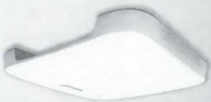
White plastic fan or vent with a small handle and ventilation grille (no text or symbols visible)- TV/AM/FM/LTE ROOFTOP ANTENNA WITH CEILING MOUNT BRACKET
- Welcome
- Supplier's Declaration of Conformity
- Unique Identifier
- Responsible Party – U.S. Contact Information
- FCC Compliance Statement
- Industry Canada Statement
- Contents
- Product Overview
- Product Features
- Installation
- What's in the Box
- Mounting the Antenna
- Making a New Opening
- Using the Existing Opening
- Installing the Ceiling Mount Bracket
- Mounting the Wall Plate
- Connections
- Wiring Diagram
- Testing the Power Supply
- Operation
- Running a Channel Scan
- Selecting TV Antenna Reception
- Selecting Cable TV
- Specifications
- FURRION
- Furrion Innovation Center & Institute of Technology
- FURRION ACCESS
- OMNI-DIRECTIONAL ROOFTOP ANTENNA
- WITH CEILING MOUNT BRACKET
- FAN73B7C | OMNI-DIRECTIONAL ROOFTOP ANTENNA WITH CEILING MOUNT BRACKET
- WARRANTY TERMS AND CONDITIONS.
Brand : Furrion
Model : FAN73B7C-BL
Category : Antenna