XM-2351 - Car speaker SONY - Free user manual and instructions
Find the device manual for free XM-2351 SONY in PDF.

User questions about XM-2351 SONY
0 question about this device. Answer the ones you know or ask your own.
Ask a new question about this device
Download the instructions for your Car speaker in PDF format for free! Find your manual XM-2351 - SONY and take your electronic device back in hand. On this page are published all the documents necessary for the use of your device. XM-2351 by SONY.
USER MANUAL XM-2351 SONY
Stereo Power Amplifier
Operating Instructions
Mode d'emploi
Owner's Record
The model and serial numbers are located on the bottom of the unit.
Record the serial number in the space provided below.
Refer to these numbers whenever you call upon your Sony dealer regarding this product.
Model No. XM-2501 Serial No.
Model No. XM-2351 Serial No.
This instruction manual covers the XM-2501 and XM-2351. The illustrations in the manual are of the XM-2501. When differences occur, they are clearly described in the corresponding sections.
Sony Corporation ©1996 Printed in Japan
Features
• Maximum power output of 100 (70)* watts per channel (at 4 ohms).
- The XM-2501/2351 can be used as a monaural amplifier with a maximum output of 260 (160)* watts.
- Dual mode connection can be made for a multi-speaker system.
• Built in protection circuit.
- Pulse power supply** for stable and regulated output power.
* XM-2351
** Pulse power supply
This unit has a built-in power regulator which converts the power supplied by the DC 12 V car battery into high speed pulses using a semiconductor switch. These pulses are stepped up by the built-in pulse transformer and separated into both positive and negative power supplies before being converted into direct current again. This is to regulate fluctuating voltage from the car battery. This light weight power supply system provides a highly efficient power supply with a low impedance output.
Caractéristiques
- Before making any connections, disconnect the ground terminal of the car battery to avoid short circuits.
- Be sure to use speakers with an adequate power rating. If you use small capacity speakers, they may be damaged.
- Do not connect the terminal of the speaker system to the car chassis, and do not connect the terminal of the right speaker with that of the left speaker.
• Install the input and output cords away from the power supply lead as running them close together can generate some interference noise. - This unit is a high powered amplifier. Therefore, it may not perform to its full potential if used with the speaker cords supplied with the car.
- If your car is equipped with a computer system for navigation or some other purpose, do not remove the ground wire from the car battery. If you disconnect the wire, the computer memory may be erased. To avoid short circuits when making connections, disconnect the +12 V power supply lead until all the other leads have been connected.
Make the terminal connections as illustrated below.
Attention
natural_image
Diagram of a mechanical assembly with a cylindrical component inserted into a housing (no text or symbols visible)Note
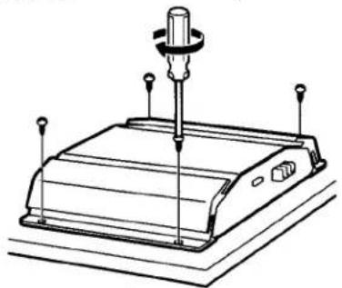
Tighten the screws firmly, but be careful not to apply too much force* as doing so may damage the screw.
* The torque value should be less than 1 N•m.
Remarque
Notes on the power supply
- Connect the +12 V power supply lead only after all the other leads have been connected.
- Be sure to connect the ground lead of the unit securely to a metal point of the car. A loose connection may cause a malfunction of the amplifier.
- Be sure to connect the remote control lead of the car audio to the remote terminal.
- Use a power supply lead with a fuse attached (25 (15)* A).
- Place the fuse in the power supply lead as close as possible to the car battery.
- During full-power operation, a current of more than 25 (15)* A will run through the system. Therefore, make sure that the leads to be connected to the +12 V and GND terminals of this unit are larger than 12 (14)*-Gauge (AWG-12 (14)*) or have a sectional area of more than 3 (2)* mm ^2 .
XM-2351
As a Monaural Amplifier
Make sure that the line output from the car audio is connected to the jack marked "L (MONO)" on the unit.
Remarque
- If you wish to use a subwoofer as the monaural speaker, connect the speaker as illustrated above. The output signals to the subwoofer will be a combination of both the right and left output signals.
- As the XM-2351 is not equipped with a low-pass filter, use a coil (not supplied) as a substitute for the low-pass filter.
Remarques
Level Adjustment Control
The input level can be adjusted with this control when using source equipment made by other manufacturers. Turn it to MAX when the output level of the car audio seems low.
- When using passive crossover networks in a multi-speaker system, care must be taken as the speaker system's impedance should not be lower than that of the suitable impedance for this unit.
- When you are installing a 12 decibels/octave system in your car, the following points must be considered. In a 12 decibels/octave system where both a choke and capacitor are used in series to form a circuit, great care must be taken when they are connected. In such a circuit, there is going to be an increase in the current which bypasses the speaker with frequencies around the crossover frequency. If audio signals continue to be fed into the crossover frequency area, it may cause the amplifier to become abnormally hot or the fuse to blow. Also if the speaker is disconnected, a series-resonant circuit will be formed by the choke and the capacitor. In this case, the Impedance in the resonance area will decrease dramatically resulting in a short circuit situation causing damage to the amplifier. Therefore, make sure that a speaker is connected to such a circuit at all times
Remarques
- This unit is designed for negative ground 12 V DC operation only.
- Use speakers with an impedance of 2 to 8 ohms (4 to 8 ohms when used as a bridging amplifier).
- Do not connect any active speakers (with built-in amplifiers) to the speaker terminals of the unit. Doing so may damage the active speakers.
- Avoid installing the unit where: — it would be subject to high temperatures such as from direct sunlight or hot air from the heater
— it would be exposed to rain or moisture — it would be subject to dust or dirt.
- If your car is parked in direct sunlight and there is a considerable rise in temperature inside the car, allow the unit to cool down before use.
- When installing the unit horizontally, be sure not to cover the fins with the floor carpet etc.
- If this unit is placed too close to the car radio, interference may occur. In this case, relocate the amplifier away from the car radio.
- If no power is being supplied to the cassette player or tuner, check the connections.
- This power amplifier employs a protection circuit* to protect the transistors and speakers if the amplifier malfunctions. Do not attempt to test the protection circuits by covering the heat sink or connecting improper loads.
- Do not use the unit with a weak battery as its optimum performance depends on a good power supply.
- For safety reasons, keep your car audio volume moderate so you can still hear sounds outside your car.
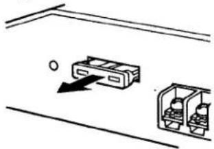
Fuse Replacement
If the fuse blows, check the power connection and replace the fuse. If the fuse blows again after replacement, there may be an internal malfunction. In such a case, consult your nearest Sony dealer.
Warning
When replacing the fuse, be sure to use one matching the amperage stated above the fuse holder. Never use a fuse with an amperage rating exceeding the one supplied with the unit as this could damage the unit.
natural_image
Simple line drawing of two mechanical components with a circular arrow indicating direction (no text or symbols)\* Protection circuit
This amplifier is provided with a protection circuit that operates in the following cases:
— when the unit is overheated
— when a DC current is generated
— when the speaker terminals are short circuited.
The color of the POWER/PROTECTOR indicator will change from green to red, and the unit will shut down. If this happens, turn off the connected equipment, take out the cassette tape or disc, and determine the cause of the malfunction. If the amplifier has overheated, wait until the unit cools down before use.
POWER/PROTECTOR indicator
natural_image
Pure technical line drawing of a mechanical bracket or frame structure without any text, numbers, or symbolsIf you have any questions or problems concerning your unit that are not covered in this manual, please consult your nearest Sony dealer.
Troubleshooting Guide
The following checklist will assist in the correction of most problems which you may encounter with your unit.
Before going through the checklist below, refer to the connection and operating procedures.
| Problem | Cause/Solution |
| The POWER/PROTECTOR indicator does not light up. | The fuse is blown. → Replace the fuse with a new one. |
| The ground lead is not securely connected. → Fasten the ground lead securely to a metal point of the car. | |
| The voltage going into the remote terminal is too low.• The connected master unit is not turned on. → Turn on the master unit.• The system employs too many amplifiers. → Use a relay. | |
| Check the battery voltage (10.5 – 16 V). | |
| • The POWER/PROTECTOR indicator flashes.• The unit becomes abnormally hot. | Use speakers with suitable impedance.• Stereo operation: 2 – 8 ohms• Bridging operation: 4 – 8 ohms |
| The speaker outputs are short-circuited. → Rectify the cause of the short-circuit. | |
| Alternator noise is heard. | The power connecting leads are installed too close to the RCA pin cords. → Keep the leads away from the cords. |
| The ground lead is not securely connected. → Fasten the ground lead securely to a metal point of the car. | |
| Negative speaker leads are touching the car chassis. → Keep the leads away from the car chassis. |
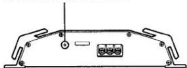
Installation
Before Installation
- Mount the unit either inside the trunk or under a seat.
- Choose the mounting location carefully so the unit will not interfere with the normal movements of the driver and it will not be exposed to direct sunlight or hot air from the heater.
- Do not install the unit under the floor carpet, where the heat dissipation from the unit will be considerably impaired.
First, place the unit where you plan to install it, and mark the positions of the four screw holes on the mounting board (not supplied). Then drill a 3 mm (1/8 in.) pilot hole at each mark and mount the unit onto the board with the supplied mounting screws. The mounting screws are all 15 mm (19/32 in.) long, so make sure that the mounting board is thicker than 15 mm (19/32 in.).
Mount the unit as illustrated below.
natural_image
Line drawing of a mechanical device with a central pin and three vertical supports (no text or symbols)Précautions
natural_image
Diagram showing two labeled electronic components with an arrow indicating direction (no text or symbols present)\* Circuit de protection
natural_image
Pure technical diagram of a mechanical or electronic component with no visible text, numbers, or symbolsnatural_image
Technical line drawing of a mechanical device with a central pin and four vertical supports (no text or symbols)Specifications
AUDIO POWER SPECIFICATIONS
POWER OUTPUT AND TOTAL HARMONIC DISTORTION
50 (35)* watts per channel minimum continuous average power into 4 ohms, both channels driven from 20 Hz to 20 kHz with no more than 0.04 % total harmonic distortion per Car Audio Ad Hoc Committee standards.
XM-2351
Other Specifications
| Circuit system | OTL (output transformerless) circuit | Power requirements | 12 V DC car battery (negative ground) |
| Pulse power supply | Power supply voltage10.5 - 16 V | ||
| Inputs | RCA pin jacks | Current drain | at rated output: 12 (8)* A (4ohms, 50 watts × 2) (4 ohms, 35 watts × 2)* at 10 % THD: 16 (10)* A |
| Outputs | Speaker terminals | ||
| Speaker impedance | 2 - 8 ohms (stereo) | ||
| 4 - 8 ohms (when used as a bridging amplifier) | Retmote input: 5 mA | ||
| Dimensions | Approx. 230 × 53 × 182( 147) * mm (w/h/d) ( 9^1/s × 2^1/s × 7^1/s( 5^7/s) ) * in.) not incl. projecting parts and controls | ||
| Maximum output at 4 ohms | 100 (70)* watts per channel | ||
| 260 (160)* watts (monaural) | |||
| Rated output (supply voltage at 14.4 V) | Mass | Approx. 2 (1.6)* kg (4 lb. 6 oz.) (3 lb. 8 oz.)* not incl. accessories | |
| Frequency response | 5 Hz - 100 kHz (*0 dB) | ||
| Harmonic distortion | 0.005 % or less (at 1 kHz, 4 ohms, 25 watts) | * XM-2351 | |
| ** XM-2501 only | |||
| Input level adjustment range | |||
| 0.2 - 4 V | Design and specifications are subject to change without notice. | ||
| Low-pass filter** | 80 Hz, -18 dB/oct | ||
| High-pass filter | 80 Hz, -12 dB/oct | ||
Spécifications