CHV-TSTATEX-W-T - Thermostat Crestron - Free user manual and instructions
Find the device manual for free CHV-TSTATEX-W-T Crestron in PDF.

User questions about CHV-TSTATEX-W-T Crestron
0 question about this device. Answer the ones you know or ask your own.
Ask a new question about this device
Download the instructions for your Thermostat in PDF format for free! Find your manual CHV-TSTATEX-W-T - Crestron and take your electronic device back in hand. On this page are published all the documents necessary for the use of your device. CHV-TSTATEX-W-T by Crestron.
USER MANUAL CHV-TSTATEX-W-T Crestron
Mount the thermostat directly to drywall or to a single-gang box in accordance with accepted building codes and practices. If using the single-gang box, be sure to fill it with thermal insulation material.

For additional details and installation options, refer to the latest version of the CHV-TSTATEX Operations & Installation Guide (Doc. 6989). It is available from the Crestron® Web site (www.crestron.com/manuals).
DIP Switch Settings
Power Steal Switch


LEFT SWITCH
| A DESCRIPTION | ON | OFF | |
| 1 | System Type HeatCool Test Pump | ||
| 3 | Heat Pump Mode Aux Heat Dual Fuel | ||
| 2 | CoolHP Stages 1 | 2 | |
| 1 | Heat Stages | 1 | 2 |
RIGHT SWITCH
| DESCRIPTION | ON | OFF | ||
| 4 | Fan in Host | Disabled | Enabled | |
| 3 | Change Over Outputs | Disabled | Enabled | |
| 2 | Cool SP Range | Normal | Extended | |
| 1 | N/A | N/A | N/A | |

Connections
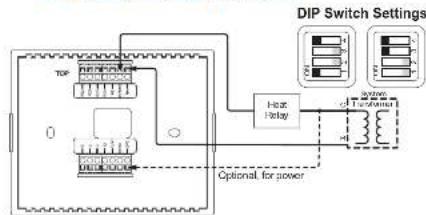
Connect the thermostat using the four most typical wiring configurations shown below as a guide. Refer to "DIP Switch Settings" on the left to configure each application. For more information, refer to the latest version of the CHV-TSTATEX Operations & Installation Guide (Doc. 6989).
Single Stage Heat-Only Application
flowchart
graph TD
    A["TDF"] --> B["Power Supply"]
    B --> C["Hot Relay"]
    C --> D["Transformer"]
    D --> E["DIP Switch Settings"]
    style A fill:#f9f,stroke:#333
    style E fill:#bbf,stroke:#333
    note right of A: "Optional for power"
    note right of E: "System for Power Input"
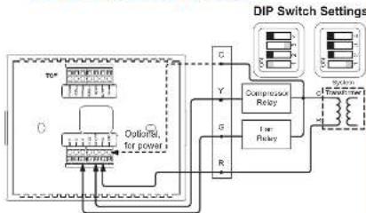
Single Stage Cool-Only Application
flowchart
graph TD
    A["Power Input"] --> B["Outfitters for power"]
    B --> C["Switch C"]
    C --> D["Compressor Relay"]
    C --> E["For Relay"]
    D --> F["Output"]
    E --> F
    F --> G["DIP Switch Settings"]
    G --> H["Output"]
    style A fill:#f9f,stroke:#333
    style H fill:#bbf,stroke:#333
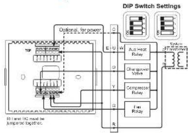
Heat Pump Application With
Integrated Controller
flowchart
graph TD
    A["Power Input"] --> B["Control Logic"]
    B --> C["Output"]
    D["Auc Heat Relay"] --> E["Chopper Power Valve"]
    E --> F["Compressor Relay"]
    F --> G["I-in Relay"]
    G --> H["Output"]
    I["DIP Switch Settings"] --> J["Output"]
    style A fill:#f9f,stroke:#333
    style D fill:#f9f,stroke:#333
    style I fill:#f9f,stroke:#333
Heat - Cool Application With
Integrated Control Unit
DIP Switch Settings
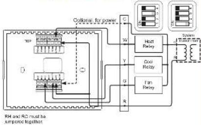
flowchart
graph TD
    A["Top 100% power"] --> B["Coilbrel for power"]
    B --> C["C"]
    B --> D["W"]
    B --> E["Y"]
    B --> F["G"]
    B --> G["R"]
    C --> H["Heat Relay"]
    D --> I["Cool Relay"]
    E --> J["Fan Relay"]
    F --> K["Transformer"]
    G --> L["Transformer"]
    H --> M["External Circuit"]
    I --> M
    J --> M
    K --> M
    L --> M
    M --> N["RL and RC must be unimposed together"]
For details, refer to the latest version of the CHV-TSTATEX Operations & Installation Guide, Doc. 6969. QUICKSTART.DOC. 6980B (2027559) 01-12
QUICKSTART DOC. 6990B (2027559) 01.12
www.crestron.com
888.273.7876201.767.3400
Open and were signed by change with local and no.

CRESTRON
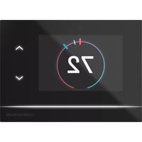
CHV-TSTATEX
infiNET EX® Thermostat

Basic Thermostat Setup

Install two AA batteries in the battery compartment. ^1
CAUTION: Replace all batteries in the CHV-TSTATEX at the same time. Mixing old and new batteries in the CHV-TSTATEX may result in battery leakage and equipment damage.
To enter Setup mode ^1 , press and hold FAN, then simultaneously press and hold ▲ and ▼ for about five seconds. The display shows the Temperature Scale function (FC).
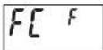
Use ▲ or ▼ to choose the temperature units: F (Fahrenheit), C1 (Celcius, whole degree set points), or C2 (Celcius, half degree set points).
-
Expected battery life is 1 year using quality alkaline batteries.
-
Refer to the latest version of the CHV-TSTATX Operations & Installation Guide (Doc. 6989) for detailed information on setup and operating modes.

Basic InfinET EX® Setup
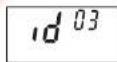
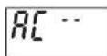
In Setup mode, press MODE until the infINET EX ID (RF ID) function is displayed (Id). Use ▲ and ▼ to choose the infINET EX ID. Press MODE until the Start infINET EX Acquire function is displayed (AC).
Put an infINET EX gateway (e.g., CEN-RFGW-EX or MC3) into Acquire mode, from the unit itself or from Crestron Toolbox™, as described in the latest revision of the CEN-RFGW-EX Operations & Installation Guide (Doc. 6706) or MC3 Operations &

Installation Guide (Doc. 7095).
Press ▲ or ▼ to start the acquire process: display shows flashing -- (in progress). When finished, display shows 00 (finished, found gateway) or E# (finished, could not find gateway), where # represents an error code.
Once all devices have been acquired, take the CEN-RFGW-EX or MC3 out of Acquire mode. Press FAN on the thermostat to exit Setup mode.

System Modes and Fan Operation
Press the MODE button to cycle the unit through available modes: Off, Heat, Emergency Heat (for heat pump and dual-fuel systems), Cool, and Auto. ^1
- Mode changes take place upon release of the MODE button.
- The selected mode becomes operational three seconds after the mode has been entered.
Press the FAN button to toggle between Fan Auto and Fan Always On modes.
• The fan icon is always displayed.
- When set to Fan Auto, the fan operates only when there is a cool or heat call. ^1,2
- In system Off mode, the fan still runs if set to Fan Always On mode.
Press MODE and FAN simultaneously to enter Hold mode. Hold mode ignores scheduled set point values from the control system.
Use the ▲ and ▼ buttons to choose the desired temperature set point.
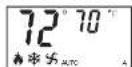
Thermostat Display Key
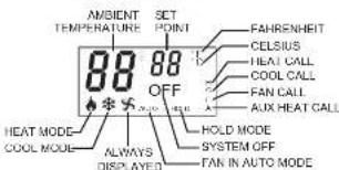
text_image
AMBIENT TEMPERATURE SET POINT FAHRENHEIT CELSIUS HEAT CALL COOL CALL FAN CALL AUX HEAT CALL 88 88 OFF AUTO HEAT MODE COOL MODE ALWAYS DISPLAYED HOLD MODE SYSTEM OFF FAN IN AUTO MODE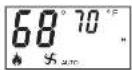
Typical Heat Mode Display
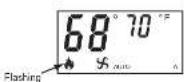
Typical Emergency Heat Mode Display
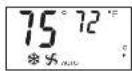
Typical Cool Mode Display
Typical
Auto Heat/Cool
Mode Display
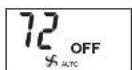
Typical Off Mode Display
-
Refer to the latest version of the CHV-TSTATEX Operations & Installation Guide (Doc. 6989) for detailed information on setup and operating modes.
-
Fan only runs during heat calls if the thermostat has been configured to do so.
The specific patents that cover Crestron products are listed at www.crestronpatens.com
Crestron, the Creation logo Crestron toolbox and in NLT LX are either trademarks or registered trademarks of Crestron Electronics, Inc. in the United States and/or other countries. Other trademarks, registered trademarks, and trade names may be used in this document to refer to other the critics claiming the marks and names of their products. Crestron declares proprietary interest in the marks and names of others. 2012 Crestron Electronics, Inc.
For details, refer to the latest version of the
CHV-TSTATEX Operations & Installation Guide, Doc. 6989.
QUICKSTART DOC. 6990B (2027559) 01.12
www.crestron.com
888.273.7876201.767.3400
Open and close was bound to change without red to.

CRESTRON