DM-RMC-200-S2 - Receiver Crestron - Free user manual and instructions
Find the device manual for free DM-RMC-200-S2 Crestron in PDF.

User questions about DM-RMC-200-S2 Crestron
0 question about this device. Answer the ones you know or ask your own.
Ask a new question about this device
Download the instructions for your Receiver in PDF format for free! Find your manual DM-RMC-200-S2 - Crestron and take your electronic device back in hand. On this page are published all the documents necessary for the use of your device. DM-RMC-200-S2 by Crestron.
USER MANUAL DM-RMC-200-S2 Crestron
DigitalMedia 8G™ Fiber Receiver and Room Controller
DO Install the Device
The Crestron® DM-RMC-200-S and DM-RMC-200-S2 mount onto a 2-gang electrical box using the included support bracket. The support bracket provides a holder for the included power pack.
Mounting the Device onto an Electrical Box
To mount the device onto an electrical box, do the following:
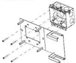
- Attach the four included 6-32 x 1-1/4" standoffs to the studs of the included support bracket.
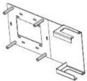
- Using the four included 6-32 x 3/4" combo truss head screws, attach the included support bracket to the electrical box.
natural_image
Technical line drawing of a mechanical assembly with no visible text or symbols- Ground the device and then connect the proper cables to the bottom of the unit.

Check the Box
QTY PRODUCT COLOR PART NUM.
| 1 Bracket, Support 2047591 | |||
| 2 Connector, 2-Pin 2003574 | |||
| 4 Connector, 2-Pin 2003582 | |||
| 2 Connector, 4-Pin 2003576 | |||
| 1 Connector, 5-Pin 2003577 | |||
| 1 Power Cord, 5' 10" (1.78 m) 2042043 | |||
| 1 Power Pack, 24 Vdc 2.5 A, 100-240 Vac 2045873 | |||
| 1 Screw, 6-32 x 1/2", Pan Head, Phillips | Black | 2007238 | |
| 4 Screw, 6-32 x 1/4", Pan Head, Phillips | Black | 2007215 | |
| 4 Screw, 6-32 x 3/4", Truss Head, Combo | 2009211 | ||
| 4 Standoff, 06-32 x 1-1/4", 1/4" OD, Hex | 2007056 | ||
| 2 Tie Wrap, Cable Tie, 15-1/2" x 1" | Black | 2013608 | |
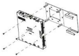
- Using the four included 6-32 x 1/4" Phillips head screws, attach the device to the standoffs.
natural_image
Technical line drawing of a mechanical assembly with no visible text or symbolsInserting the Power Pack into the Power Pack Holder
To insert the power pack into the power pack holder, do the following:
- Slide the power pack into the power pack holder.
- Using the included 6-32 x 1/2" Phillips pan head screw, thread the screw through either of the two provided screw holes to hold the power pack in place.
- Bundle the excess cable of the power pack into a loop, and then fasten the bundled cable to the power pack holder by doing the following:
a. Insert one of the included tie wraps through one of the tie wrap holes in the power pack holder.
b. Wrap the tie wrap around the bundled cable.
c. Repeat steps 3a and 3b if necessary using the other included tie wrap and the remaining tie wrap hole in the power pack holder.
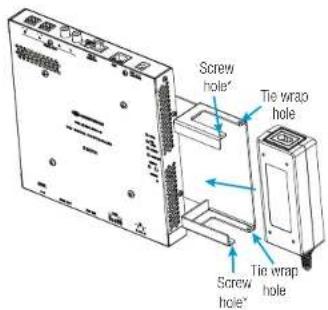
"Use either screw hole for the included 6-32 x 1/2" Phillips pan head screw.
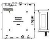
Installation of the power pack in the holder appears as shown below.

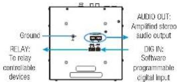
DO Complete the Connections
Make additional connections as appropriate for the application.
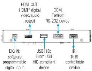
DM-RMC-200-S and DM-RMC-200-S2 Front Panel Connections
DM-RMC-200-S Rear Panel Connections
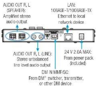
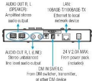
DM-RMC-200-S2 Rear Panel Connections
DO Set the IP Address
The configuration of the receiver within the DigitalMedia 8G ^TM system determines how the IP address of the receiver is set:
- If the receiver connects to a DigitalMedia™ switcher, the receiver is configured by the switcher automatically.
- If the receiver connects to a DigitalMedia 8G fiber transmitter, the receiver uses its own configuration settings. By default, DHCP (Dynamic Host Configuration Protocol) is enabled. If it is desired, assign the default IP address to the receiver by holding down the SETUP button while the unit boots up. The default IP address overwrites the current setting. The default IP address of the DM-RMC-200-S and DM-RMC-200-S2 is 192.168.1.248. To manually set a different IP address, use Crestron Toolbox™ application.
DO Learn More
Visit the website for additional information and the latest firmware updates. To learn more about this product, use a QR reader application on your mobile device to scan the QR images.
Crestron Electronics
15 Volvo Drive, Rockleigh, NJ 07647
888.CRESTRON | www.crestron.com
DM-RMC-200-S

DM-RMC-200-S2


As of the date of manufacture, the products have been tested and found to comply with specifications for CE marking.

This product is listed to applicable UL Standards and requirements by Underwriters Laboratories Inc. Ce produit est homologué selon les normes et les exigences UL applicables par Underwriters Laboratories Inc.
Federal Communications Commission (FCC) Compliance Statement
This device complies with part 15 of the FCC Rules. Operation is subject to the following two conditions:
(1) This device may not cause harmful interference, and (2) this device must accept any interference received, including interference that may cause undesired operation.
CAUTION: Changes or modifications not expressly approved by the manufacturer responsible for compliance could void the user's authority to operate the equipment.
NOTE: This equipment has been tested and found to comply with the limits for a Class A digital device, pursuant to part 15 of the FCC Rules. These limits are designed to provide reasonable protection against harmful interference when the equipment is operated in a commercial environment. This equipment generates, uses, and can radiate radio frequency energy and, if not installed and used in accordance with the instruction manual, may cause harmful interference to radio communications. Operation of this equipment in a residential area is likely to cause harmful interference in which case the user will be required to correct the interference at his own expense.
Industry Canada (IC) Compliance Statement
CAN ICES-3(A)/NMB-3(A)


The products are class 1 laser products. They comply with safety regulations of IEC-60825-1, FDA 21 CFR 1040 11 and FDA 21 CFR 1040 10.
WARNING: Visible and Invisible laser radiation when open. Avoid direct exposure to beam.
NOTE: Plug the included dust cap into the optical transceiver when the fiber optic cable is unplugged.
WARNING: These are Class A products. In a domestic environment these products may cause radio interference in which case the user may be required to take adequate measures.
The specific patents that power Crestron products are listed at www.crestron.com. The product warranty can be found at www.crestron.com warranty
Crestron, the Crestron logo, Crestron Techlab, DigitalMedia, DigitalMedia SE, and IBM are either trademarks or registered trademarks of Crestron Electronics, Inc. in the United States under other countries. HDMI and the HDMI logo are other trademarks or registered trademarks of HDMI Licensing LLC in the United States under other countries. U.S. and the U.K. logos are either trademarks or registered trademarks of Underwriters Laboratories, Inc., in the United States and/or other countries. Other trademarks, registered trademarks, and trade names may be used in this document to refer to either the entities charging the marks and names or their products. Crestron denotes any proprietary interest in the marks and names of others. Crestron is not responsible for author in typography or photography.
This document was written by the Technical Publications department at Creation
©2016 Compression Electronics, Inc.

CRESTRON. DO GUIDE
DOC. 7810B (2044421) 09.16
Specifications subject to change without notice.