BC-80 - Camcorder DataVideo - Free user manual and instructions
Find the device manual for free BC-80 DataVideo in PDF.


| Product Type | HD Block Camera |
| Model | BC-80 |
| Brand | Datavideo |
| Image Sensor | 1/2.8" Exmor CMOS, 2.38 Megapixels effective |
| Video Output | HDMI (v1.3) x1, HD-SDI x1 |
| Optical Zoom | 30x |
| Focal Length | 4.3 mm (WIDE) to 129 mm (TELE), F1.6 to F4.7 |
| Control Protocols | VISCA (RS-422), DVIP (Ethernet) |
| Control Interfaces | RS-422 (RJ-45), DVIP (RJ-45), IR Remote |
| Power Supply | DC 12V, 1A (10W) |
| Dimensions (W x H x D) | 71.4 x 82.6 x 202.05 mm (without tripod adapter) |
| Weight | 0.7 kg |
| Operating Temperature | 0°C to 40°C (32°F to 104°F) |
| Storage Temperature | -10°C to 60°C (14°F to 140°F) |
| Humidity | 10% to 80% (non-condensing) |
| Supported Video Formats | 1080p/59.94, 1080p/50, 1080p/29.97, 1080p/25; 1080i/59.94, 1080i/50; 720p/59.94, 720p/50 |
| White Balance Modes | AWB, MWB, One Push, Indoor (3200K), Outdoor (5600K), Fluorescent (4200K) |
| Focus | Auto / Manual |
| Iris Control | Auto / Manual |
| Digital Noise Reduction | 0 to 5 levels |
| Mirror Function | Off, Horizontal, Vertical, H+V |
| Tally Light | Green (normal), Red (booting) |
| Firmware Update | Via USB port (FAT32, <16 GB) |
| OSD Menu | English |
| Included Accessories | IR remote control, power supply |
| Safety Compliance | FCC Part 15 |
| Warranty | 1 year standard (3 years with registration) |
| Repairability | Refer to qualified service personnel; do not attempt self-service |
| Cleaning | Unplug, use damp cloth; no liquid or aerosol cleaners |
Frequently Asked Questions - BC-80 DataVideo
User questions about BC-80 DataVideo
0 question about this device. Answer the ones you know or ask your own.
Ask a new question about this device
Download the instructions for your Camcorder in PDF format for free! Find your manual BC-80 - DataVideo and take your electronic device back in hand. On this page are published all the documents necessary for the use of your device. BC-80 by DataVideo.
USER MANUAL BC-80 DataVideo
natural_image
Technical line drawing of a cylindrical electronic device with mounting flanges and internal components (no text or symbols)BLOCK CAMERA
BC-80
Instruction Manual
www.datavideo.com
Table of Contents
FCC COMPLIANCE STATEMENT .... 4
WARNINGS AND PRECAUTIONS ...... 4
WARRANTY 5
STANDARD WARRANTY 5
THREE YEAR WARRANTY....6
DISPOSAL....7
- INTRODUCTION......8
1.1 FEATURES....8
-
SYSTEM DIAGRAM....9
-
CONNECTIONS.... 10
3.1 FRONT VIEW ....10
3.2 REAR PANEL....11
-
IR REMOTE CONTROL .... 14
-
OSD MENU OPTIONS....19
-
DIP SWITCH SETTINGS 29
-
RMC-180 PTZ CAMERA CONTROL UNIT.... 30
DIRECT CONNECTION TO CAMERA....30
8.1.1 User Interface....32
8.1.2 Device Search 34
8.1.3 Clearing Device List 34
8.1.4 Detailed Device Network Information......35
8.1.5 Modify Device Information and Write to Device .... 36
8.1.6 Switch to Other Network Interface ......37
8.1.7 Language Selection 38
-
FIRMWARE UPGRADE...... 39
-
DIMENSIONS 40
-
SPECIFICATIONS.... 41
SERVICE AND SUPPORT 44
Disclaimer of Product & Services
The information offered in this instruction manual is intended as a guide only. At all times, Datavideo Technologies will try to give correct, complete and suitable information. However, Datavideo Technologies cannot exclude that some information in this manual, from time to time, may not be correct or may be incomplete. This manual may contain typing errors, omissions or incorrect information. Datavideo Technologies always recommend that you double check the information in this document for accuracy before making any purchase decision or using the product. Datavideo Technologies is not responsible for any omissions or errors, or for any subsequent loss or damage caused by using the information contained within this manual. Further advice on the content of this manual or on the product can be obtained by contacting your local Datavideo Office or dealer.
FCC Compliance Statement
This device complies with part 15 of the FCC rules. Operation is subject to the following two conditions:
(1) This device may not cause harmful interference, and
(2) This device must accept any interference received, including interference that may cause undesired operation.
Warnings and Precautions

- Read all of these warnings and save them for later reference.
- Follow all warnings and instructions marked on this unit.
- Unplug this unit from the wall outlet before cleaning. Do not use liquid or aerosol cleaners. Use a damp cloth for cleaning.
- Do not use this unit in or near water.
- Do not place this unit on an unstable cart, stand, or table. The unit may fall, causing serious damage.
- Slots and openings on the cabinet top, back, and bottom are provided for ventilation. To ensure safe and reliable operation of this unit, and to protect it from overheating, do not block or cover these openings. Do not place this unit on a bed, sofa, rug, or similar surface, as the ventilation openings on the bottom of the cabinet will be blocked. This unit should never be placed near or over a heat register or radiator. This unit should not be placed in a built-in installation unless proper ventilation is provided.
- This product should only be operated from the type of power source indicated on the marking label of the AC adapter. If you are not sure of the type of power available, consult your Datavideo dealer or your local power company.
- Do not allow anything to rest on the power cord. Do not locate this unit where the power cord will be walked on, rolled over, or otherwise stressed.
-
If an extension cord must be used with this unit, make sure that the total of the ampere ratings on the products plugged into the extension cord do not exceed the extension cord rating.
-
Make sure that the total amperes of all the units that are plugged into a single wall outlet do not exceed 15 amperes.
- Never push objects of any kind into this unit through the cabinet ventilation slots, as they may touch dangerous voltage points or short out parts that could result in risk of fire or electric shock. Never spill liquid of any kind onto or into this unit.
- Except as specifically explained elsewhere in this manual, do not attempt to service this product yourself. Opening or removing covers that are marked “Do Not Remove” may expose you to dangerous voltage points or other risks, and will void your warranty. Refer all service issues to qualified service personnel.
- Unplug this product from the wall outlet and refer to qualified service personnel under the following conditions:
a. When the power cord is damaged or frayed;
b. When liquid has spilled into the unit;
c. When the product has been exposed to rain or water;
d. When the product does not operate normally under normal operating conditions. Adjust only those controls that are covered by the operating instructions in this manual; improper adjustment of other controls may result in damage to the unit and may often require extensive work by a qualified technician to restore the unit to normal operation;
e. When the product has been dropped or the cabinet has been damaged;
f. When the product exhibits a distinct change in performance, indicating a need for service.
Warranty
Standard Warranty
- Datavideo equipment are guaranteed against any manufacturing defects for one year from the date of purchase.
-
The original purchase invoice or other documentary evidence should be supplied at the time of any request for repair under warranty.
-
The product warranty period begins on the purchase date. If the purchase date is unknown, the product warranty period begins on the thirtieth day after shipment from a Datavideo office.
- All non-Datavideo manufactured products (product without Datavideo logo) have only one year warranty from the date of purchase.
- Damage caused by accident, misuse, unauthorized repairs, sand, grit or water is not covered under warranty.
- Viruses and malware infections on the computer systems are not covered under warranty.
- Any errors that are caused by unauthorized third-party software installations, which are not required by our computer systems, are not covered under warranty.
- All mail or transportation costs including insurance are at the expense of the owner.
- All other claims of any nature are not covered.
- All accessories including headphones, cables, and batteries are not covered under warranty.
- Warranty only valid in the country or region of purchase.
- Your statutory rights are not affected.
Three Year Warranty
- All Datavideo products purchased after July 1st, 2017 are qualified for a free two years extension to the standard warranty, providing the product is registered with Datavideo within 30 days of purchase.

- Certain parts with limited lifetime expectancy such as LCD panels, DVD drives, Hard Drive, Solid State Drive, SD Card, USB Thumb Drive, Lighting, Camera module, PCIe Card are covered for 1 year.
- The three-year warranty must be registered on Datavideo's official website or with your local Datavideo office or one of its authorized distributors within 30 days of purchase.
Disposal
For EU Customers only - WEEE Marking
This symbol on the product or on its packaging indicates that this product must not be disposed of with your other household waste. Instead, it is your responsibility to dispose of your waste equipment by handing it over to a designated collection point for the recycling of waste electrical and electronic equipment. The separate collection and recycling of your waste equipment at the time of disposal will help to conserve natural resources and ensure that it is recycled in a manner that protects human health and the environment. For more information about where you can drop off your waste equipment for recycling, please contact your local city office, your household waste disposal service or the shop where you purchased the product.
CE Marking is the symbol as shown on the left of this page. The letters "CE" are the abbreviation of French phrase "Conformité Européenne" which literally means "European Conformity". The term initially used was "EC Mark" and it was officially replaced by
"CE Marking" in the Directive 93/68/EEC in 1993. "CE Marking" is now used in all EU official documents.
1. Introduction
The BC-80 Block Camera is a small HD camera with an infra-red remote control. It can be used for HD high quality shooting in an environment where space is limited. The image resolution is 1920x1080. The BC-80 provides 30x optical focus, and the image output interfaces are SDI and HDMI. A tally light indicator sits above the BC-80 camera lens. The control protocol supports SONY VISCA so that the camera can be controlled via RS-422 or DVIP interface.
1.1 Features
- HD Resolution: 1/2.8" High Definition 2.0 M Pixels progressive CMOS sensor
- 30x optical zoom
- High definition formats supported: 1080p/59.94, 1080p/50, 1080p/29.97, 1080p/25 1080i/59.94, 1080i/50 720p/59.94, 720p/50
- Digital Noise Reduction Function (DNR) to reduce the noise and enable clearer image under low light conditions.
• Video Output: SDI + HDMI synchronously.
• Tally LED Design (RS-422/ DVIP Operation)
• Supports SONY VISCA Protocol
• Supports DVIP Control Protocol
- Users can save up to 10 sets of preset camera settings for future filming.
- Users can control up to 4 BC-80 devices simultaneously via the RMC-180 PTZ camera remote control unit (including White Balance, Focus, Iris, Shutter Speed, Zoom, Zoom Speed, Save Preset, Recall Preset)
P.S. Shutter speed function must be set by the RMC-180 menu.
- System Diagram

flowchart
graph TD
    A["Projector"] --> B["Monitor"]
    B --> C["Lookback Kit 22" Monitor"]
    C --> D["Document Camera Projector"]
    D --> E["Apple TV or Chrome Case"]
    E --> F["Document Camera"]
    F --> G["Full Shot Camera BC-AD"]
    G --> H["Multi-view"]
    H --> I["PCM"]
    I --> J["Se-1200 U8"]
    J --> K["Home Splitter"]
    K --> L["PPT"]
    L --> M["Close Audio"]
    M --> N["VOOD System"]
    N --> O["ICP/B"]
    O --> P["Big Screen"]
    P --> Q["Hardware"]
    Q --> R["HDMI"]
    R --> S["Video Streaming Server Use Screening Kit And Backup Recorder"]
    S --> T["NVS-23 Video Streaming Server Use Screening Kit And Backup Recorder"]
    T --> U["HDMI-70 Digital Video Recorder"]
    U --> V["Video Streaming Server Use Screening Kit And Backup Recorder"]
    V --> W["LINK"]
    W --> X["Big Screen"]
    X --> Y["HDMI"]
    Y --> Z["Video Streaming Server Use Screening Kit And Backup Recorder"]
    Z --> AA["LINK"]
    AA --> AB["Big Screen"]
    AB --> AC["HDMI"]
    AC --> AD["Video Streaming Server Use Screening Kit And Backup Recorder"]
    AD --> AE["LINK"]
    AE --> AF["Big Screen"]
    AF --> AG["HDMI"]
    AG --> AH["Video Streaming Server Use Screening Kit And Backup Recorder"]
    AH --> AI["LINK"]
    AI --> AJ["Big Screen"]
    AJ --> AK["HDMI"]
    AK --> AL["Video Streaming Server Use Screening Kit And Backup Recorder"]
    AL --> AM["LINK"]
    AM --> AN["Big Screen"]
    AN --> AO["HDMI"]
    AO --> AP["Video Streaming Server Use Screening Kit And Backup Recorder"]
    AP --> AQ["LINK"]
    AQ --> AR["Big Screen"]
    AR --> AS["HDMI"]
    AS --> AT["Video Streaming Server Use Screening Kit And Backup Recorder"]
    AT --> AU["LINK"]
    AU --> AV["Big Screen"]
    AV --> AW["HDMI"]
    AW --> AX["Video Streaming Server Use Screening Kit And Backup Recorder"]
    AX --> AY["LINK"]
    AY --> AZ["Big Screen"]
3. Connections
3.1 Front View

| IR Receiver | Receives signal from the IR remote control. |
| Tally Light | As the camera is booting the tally light stays solid green and turns solid red for about three seconds just before the boot is complete. The tally light remains solid green after the camera finishes booting.Green: Camera is operating normally.Red: Camera is booting. |
| Lens | Camera lens for capturing images. |
3.2 Rear Panel


SDI Output
Video output connected to SDI monitor.
HDMI Output
Video output connected to HDMI port of the monitor.

RS-422 Control Port
Remote control port using the RS-422 control protocol. See RS-422 Control Protocol for details.

12V DC Power IN
DC in socket connects the supplied 12V PSU. The connection can be secured by screwing the outer fastening ring of the DC In plug to the socket.

Power Switch
Turns ON/OFF the camera.

Power LED Indicator
Green: Power ON OFF: Power OFF

DVIP Control Port
Remote control port using the DVIP control protocol. See DVIP Control Operation Guide for details.

Firmware Upgrade Port
Connects USB drive for firmware upgrade. For details, please refer to the Firmware Upgrade section.

DIP Switch
DIP Switch sets the camera VISCA ID, Remote Control Protocol, and Resolution, Video Mode Selection Method, and Camera ID Assignment. For details, please refer to the DIP Switch Settings section.
4. IR Remote Control
Use the IR remote control that comes with the product package to operate the BC-80 Block Camera. The IR remote control functions are described in the table below.

| No | Item | Description |
| 1 | Reset  | Press RESET or XYZ button to return the camera lens to the default zoom position (Z:0000). |
| 2 | Group | Not Applicable |
| 3 | Camera Select | Select CAM1-CAM4 in a multi-camera environmentPress Camera Select buttons to select a camera from Camera 1 to Camera 4 in a multi-camera environment.However before using the Camera Select function, first assign an ID number (CAM 1 – CAM 4) to the camera intended for remote control operation by adjusting the DIP switch located at the rear of the camera. Please refer toDIP Switch Settingssection for details. |
| 4 | Preset Setting | Not Applicable |
| 5 | Focus Setup | Manually focus camera lens on a subjectPress either (F) FAR button or (N)NEAR button to manually focus the camera lens onto the subject.Before using manual focus, make sure Auto Focus mode is turned off by pressing the AUTO FOCUSbutton. |
| 6 | Auto Focus Control | Automatically focus camera lens on a subjectPress AUTO FOCUS button and camera lens will be automatically focused on the subject. |
| 7 | Gain Control | Adjust BrightnessPress GAIN+ button to increase the brightness or GAIN- button to decrease the brightness.Press AUTO button to activate auto Gain Control and press again to exit. |
| 8 | P/T Speed | Adjust Pan/ Tilt SpeedNot Applicable |
| 9 | Iris Control | Make the subject appear brighterAdjust the iris opening (aperture), to control the amount of light coming through the lens (i.e. the "exposure"). Press IRIS+ button to enlarge the iris opening to allow more light to come in so that the subject appears brighter and press IRIS- button to shrink the iris opening to allow less light to come in so that the subject appears less bright.Press AUTO button activate auto Iris Control and press again to exit. |
| 10 | ENTER | ENTERPress ENTER key to select a particular menu option or confirm a parameter value. |
| 11 | Direction Arrows | Browse Menu OptionsPress UP, DOWN, LEFT and RIGHTarrow buttons to browse the menu options or adjust parameter values. |
| 12 | Enter/ Exit Camera Menu | Press the MENU button to Enter or Exit the Camera OSD Menu |
| 13 | Zoom In/Out Buttons | ZoomPress either (T) TELE button to zoom in on the subject such that it appears to be close to the camera or (W) WIDE button to zoom out from the subject such that it appears to be far away from the camera. |
| 14 | Zoom Speed Buttons(4 speed selection) | Adjust Zoom In/Out SpeedPress the ZOOM SPEED buttons to switch to different zoom speeds (4 being the highest and 1 being the lowest). |
| 15 | Power Button | Switch ON/OFF camera |
5. OSD Menu Options
On-Screen Menu allows the user to change various camera settings such as shooting conditions and the system setup. Press Menu button on the IR remote control to enter the on-screen menu as shown below.
[MAIN MENU]
1: Camera Set (Normal)
2: Video Output
3: Remote Control
4: System
5: Camera Set (Advance)
6: Escape
| Main Menu | |
| 1. Camera Set (Normal) | White BalanceColor temperature adjustment to make the image look more natural. |
| IRISThis is an adjustable aperture used to control the amount of light coming through the lens. The more the iris is opened, the more light it lets in and the brighter the scene will be. | |
| AGCThe setting that automatically adjusts the amplification of the signal from the camera sensor. | |
| DNRDigital Noise Reduction digitally removes any noise found in each image, resulting in a clearer image. | |
| 2. Video Output | Selection WayThis option configures how you can select the video mode.Enabling DIP SW 8 allows you to use the DIP switch to set the video mode instead of the remote control. |
| PatternPattern generates color bars for color calibration. | |
| 3. Remote Control | Remote control settings |
| 4. System | System configuration |
| 5. Camera Set (Advance) | Fog CorrectionWhen the surrounding area of the subject is foggy and of a low contrast, turning on fog correction will make the subject appear clearer. |
| ApertureAperture adjusts the image sharpness.Increasing the aperture setting so that the foreground and background of your images appear sharp. | |
| Vivid EffectVivid effect adjusts the color saturation which is basically the intensity of color in an image. | |
| Pedestal EffectThe pedestal effect enables exposure compensation which will engage the iris or auto gain control depending on the shooting situation. For best results we recommend setting the pedestal effect to 4 or 5. The pedestal effect allows the camera to brighten up the image captured as you zoom in. | |
| Backlight CorrectionUse this function when the background is brighter than the subject. | |
| 6. Escape | Exits the MENU |
| Main Options | Camera Set (Normal) | Video Output | Remote Control | System | Camera Set (Advance) | Escape |
| Sub-Options | 1. Camera Name | 1. Selection Way | 1. Remote Source | 1. Display | 1. Camera Name | |
| 2. Mirror | 2. Video Mode | 2. Set RS-422 | 2. Tally Light | 2. Mirror | ||
| 3. White Balance | 3. Pattern | 3. Set DVIP | 3. Reset All | 3. White Balance | ||
| 4. Focus | 4. Escape | 4. Set IR | 4. Update Software | 4. Focus | ||
| 5. Iris | 5. Escape | 5. Escape | 5. Iris | |||
| 6. AGC | 6. AGC | |||||
| 7. Escape | 7. Fog Correction | |||||
| 8. Aperture | ||||||
| 9. Vivid Effect | ||||||
| 10. Pedestal Effect | ||||||
| 11. Backlight Correction | ||||||
| 12. Day/Night Mode | ||||||
| 13. Shutter | ||||||
| 14. Gamma Mode | ||||||
| 15. WD Mode | ||||||
| 16. HR Mode | ||||||
| 17. Contrast | ||||||
| 18. Escape |
| First Level Main Options | Second Level Sub-Options | Third Level Parameters | Fourth Level Parameters | Sub-Option Descriptions |
| 1. Camera Set (Normal) | 1. Camera Name | NAME | ||
| DISPLAY SW | ON/OFF | |||
| POSITION | LOWER LEFT | |||
| UPPER LEFT | ||||
| LOWER RIGHT | ||||
| UPPER RIGHT | ||||
| ESCAPE | ||||
| 2. Mirror | H+V | |||
| V | ||||
| H | ||||
| OFF | ||||
| 3. White Balance | MODE | AWB(AUTO) | ||
| AWC (ONE PUSH) | ||||
| MWB (MANUAL) | ||||
| 3200K (INDOOR) | ||||
| 5600K (OUTDOOR) | ||||
| 4200K (FLUO) | ||||
| SMART ATW | OFF | |||
| SMART1/2/3 | ||||
| MWB RED COMPONENT | 0~128~255 | (Enabled when MODE is set to MWB (MANUAL)) | ||
| MWB BLUE COMPONENT | 0~128~255 | (Enabled when MODE is set to MWB (MANUAL)) | ||
| ESCAPE | ||||
| 4. Focus | FOCUS MODE | AUTO | ||
| MANUAL | ||||
| AF SENSITIVITY | LOW | |||
| NORMAL | ||||
| FOCUS SPEED | 1~8 | |||
| ESCAPE | ||||
| 5. Iris | IRIS MODE | AUTO IRIS | ||
| MANUAL | ||||
| MANUAL IRIS LEVEL | F1.6 | |||
| F2.0 | ||||
| F2.4 | ||||
| F2.8 | ||||
| F3.4 | ||||
| F4 | ||||
| F4.8 | ||||
| F5.6 | ||||
| F6.8 | ||||
| F8 | ||||
| F9.6 | ||||
| F11 | ||||
| F14 | ||||
| CLOSE | ||||
| ESCAPE | ||||
| 6. AGC | DAY (COLOR) AGC | AGC MODE | OFF | |
| ON | ||||
| MANUAL GAIN | 0 dB ~ GAIN LIMIT | |||
| GAIN LIMIT | 9 dB | |||
| 12 dB | ||||
| 15 dB | ||||
| 18 dB | ||||
| 21 dB | ||||
| 24 dB | ||||
| 27 dB | ||||
| 30 dB | ||||
| 33 dB | ||||
| 36 dB | ||||
| 39 dB | ||||
| ESCAPE | ||||
| DNR | DNR (AT AGC ON) | ON | ||
| OFF | ||||
| DNR LEVEL | 0 | |||
| 1 | ||||
| 2 | ||||
| 3 | ||||
| 4 | ||||
| 5 | ||||
| ESCAPE | ||||
| ESCAPE | ||||
| 7. Escape | ||||
| 2. Video Output | 1. Selection Way | BY MENU | ||
| BY SWITCH | ||||
| 2. Video Mode | 1080i59.94 | |||
| 1080i50 | ||||
| 720p59.94 | ||||
| 720p50 | ||||
| 1080p59.94 | ||||
| 1080p50 | ||||
| 1080p29.97 | ||||
| 1080p25 | ||||
| 3. Pattern | OFF | |||
| COLOR BAR | ||||
| 4. Escape | ||||
| 3. Remote Control | 1. Remote Source | RS-422, SW | (Configurable using DIP switch bit 4 ONLY) | |
| DVIP, SW | ||||
| 2. Set RS-422 | CAMERA ID MODE | BY MENU | ||
| BY SWITCH | ||||
| CAMERA ID | 1~7 | |||
| RS-422 BAUD RATE | 9600 | |||
| 19200 | ||||
| 38400 | ||||
| 115200 | ||||
| ESCAPE | ||||
| 3. Set DVIP | DVIP BAUD RATE | 9600 | ||
| 19200 | ||||
| 38400 | ||||
| 57600 | ||||
| 115200 | ||||
| ESCAPE | ||||
| 4. Set IR | IR GROUP ID | CAM1~4 | (Configurable using DIP switch bit 9/10 ONLY) | |
| ESCAPE | ||||
| 5. Escape | ||||
| 4. System | 1. Display | ZOOM OSD | ZOOM OSD | ON/OFF |
| ESCAPE | ||||
| DEBUG OSD | DEBUG IR OSD | ON/OFF | ||
| DEBUG CAM. OSD | ON/OFF | |||
| DEBUG RS-422 OSD | ON/OFF | |||
| DEBUG DVIP OSD | ON/OFF | |||
| DEBUG REG OSD | ON/OFF | |||
| DEBUG FRAME NO | ON/OFF | |||
| PWR ON CAM TEST | ON/OFF | |||
| DUAL LVDS TEST | ON/OFF | |||
| INT. COLOR BAR | ON/OFF | |||
| ESCAPE | ||||
| Escape | ||||
| 2. Tally Light | RED/GREEN | |||
| GREEN | ||||
| RED | ||||
| OFF | ||||
| 3. Reset All | YES/NO | |||
| 4. Update Software | SW VERSION | ESCAPE | ||
| MB CPU | V00.31b | |||
| MB FPGA | V006 | |||
| UPDATE ALL | YES/NO | |||
| ESCAPE | ||||
| 5. Escape | ||||
| 5. Camera Set (ADVANCE) | 1. Camera Name | NAME | ||
| DISPLAY SW | ON/OFF | |||
| POSITION | UPPER LEFT | |||
| LOWER RIGHT | ||||
| UPPER RIGHT | ||||
| LOWER LEFT | ||||
| ESCAPE | ||||
| 2. Mirror | H+V | |||
| V | ||||
| H | ||||
| OFF | ||||
| 3. White Balance | MODE | AWB (AUTO) | ||
| AWC (ONE PUSH) | ||||
| MWB (MANUAL) | ||||
| 3200K (INDOOR) | ||||
| 5600K (OUTDOOR) | ||||
| 4200K (FLUO) | ||||
| SMART ATW (Enabled in AWB (AUTO) mode) | OFF | |||
| SMART1~3 | ||||
| MWB RED COMPONENT (Enabled in MWB (Manual) mode) | 0~128~255 | |||
| MWB BLUE COMPONENT (Enabled in MWB (Manual) mode) | 0~128~255 | |||
| ESCAPE | ||||
| 4. Focus | FOCUS MODE | AUTO | ||
| MANUAL | ||||
| AF SENSITIVITY | LOW | |||
| NORMAL | ||||
| FOCUS SPEED | 1 | |||
| 2 | ||||
| 3 | ||||
| 4 | ||||
| 5 | ||||
| 6 | ||||
| 7 | ||||
| 8 | ||||
| ESCAPE | ||||
| 5. Iris | IRIS MODE | AUTO | ||
| MANUAL | ||||
| Manual IRIS LEVEL | F1.6 | |||
| F2.0 | ||||
| F2.4 | ||||
| F2.8 | ||||
| F3.4 | ||||
| F4 | ||||
| F4.8 | ||||
| F5.6 | ||||
| F6.8 | ||||
| F8 | ||||
| F9.6 | ||||
| F11 | ||||
| F14 | ||||
| CLOSE | ||||
| ESCAPE | ||||
| 6. AGC | AGC MODE | ON/OFF | ||
| DAY (COLOR) AGC | MANUAL GAIN | 0dB~GAIN LIMIT | ||
| GAIN LIMIT | 9 dB | |||
| 12 dB | ||||
| 15 dB | ||||
| 18 dB | ||||
| 21 dB | ||||
| 24 dB | ||||
| 27 dB | ||||
| 30 dB | ||||
| 33 dB | ||||
| 36 dB | ||||
| 39 dB | ||||
| ESCAPE | ||||
| DNR | DNR(AT AGCON) | ON | ||
| OFF | ||||
| DNR LEVEL | 0 | |||
| 1 | ||||
| 2 | ||||
| 3 | ||||
| 4 | ||||
| 5 | ||||
| ESCAPE | ||||
| 7. Fog Correction | FOG CORRECTION | OFF/ON | ||
| ESCAPE | ||||
| 8. Aperture | 0~15 | |||
| 9. Vivid Effect | 0~14 | |||
| 10. Pedestal Effect | 0~14 | |||
| 11. Backlight Correction | OFF/ON | (This option is enabled after AGC is turned on) | ||
| 12. Day/Night Mode | B/W | |||
| COLOR | ||||
| 13. Shutter | SHUTTER SPEED | 1/25 | ||
| 1/30 | ||||
| 1/50 | ||||
| 1/60 | ||||
| 1/75 | ||||
| 1/90 | ||||
| 1/100 | ||||
| 1/120 | ||||
| 1/125 | ||||
| 1/150 | ||||
| 1/180 | ||||
| 1/215 | ||||
| 1/250 | ||||
| 1/300 | ||||
| 1/350 | ||||
| 1/425 | ||||
| 1/500 | ||||
| 1/600 | ||||
| 1/725 | ||||
| 1/1000 | ||||
| 1/1250 | ||||
| 1/1500 | ||||
| ESCAPE | ||||
| 14. Gamma Mode | STANDARD MODE1 (WD OFF)MODE2 (WD OFF)MODE3 (WD OFF)MODE4 (WD OFF) | |||
| 15. WD Mode | VE/ON/OFF | (This option is enabled after AGC is turned on) | ||
| 16. HR Mode | ON/OFF | |||
| 17. Contrast | 0-31 | Default is 16 | ||
| 18. Escape | ||||
| 6. Escape | ||||
6. DIP Switch Settings

| DIP SW 1/2/3 | VISCA ID |
| ON / OFF / OFF | VISCA-ID 1 |
| OFF / ON / OFF | VISCA-ID 2 |
| ON / ON / OFF | VISCA-ID 3 |
| OFF / OFF / ON | VISCA-ID 4 |
| ON / OFF / ON | VISCA-ID 5 |
| OFF / ON / ON | VISCA-ID 6 |
| ON / ON / ON | VISCA-ID 7 |
| DIP SW 4 | Remote Control Protocol |
| ON | DVIP |
| OFF | RS-422 |
| DIP SW 5/6/7 | Resolution |
| OFF / OFF / OFF | 1920x1080i59.94 |
| ON / OFF / OFF | 1920x1080i50 |
| OFF / ON / OFF | 1280x720p59.94 |
| ON / ON / OFF | 1280x720p50 |
| OFF / ON / ON | 1920x1080p59.94 |
| ON / ON / ON | 1920x1080p50 |
| OFF / OFF / ON | 1920x1080p29.97 |
| ON / OFF / ON | 1920x1080p25 |
| DIP SW 8 | Video Mode Selection Method |
| ON | ON = video mode selectable by DIP switch only |
| OFF | OFF = video mode selectable by menu |
| DIP SW 9/10 | Camera Select Function (IR Remote Control) – Camera ID Assignment |
| OFF / OFF | CAM 1 |
| ON / OFF | CAM 2 |
| OFF / ON | CAM 3 |
| ON / ON | CAM 4 |
7. RMC-180 PTZ Camera Control Unit
The RMC-180 PTZ Camera Controller is designed to control up to 4 Datavideo Block/Pan Tilt Zoom (PTZ) cameras such as the BC-80.
The four RJ-45 ports provided on the RMC-180 rear serve to connect Block/PTZ cameras, thus allowing the user to use any RJ-45 cable to connect the RMC-180 to the RS-422 port located on the Block/PTZ camera's rear panel. The communication protocol is VISCA.
Note: Before connecting the camera to these channel ports, please set bit 4 of the camera DIP switch located at the bottom to OFF.
Direct Connection to Camera
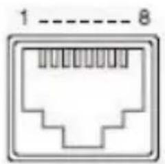
To use the RMC-180 PTZ Camera Control Unit to directly control the BC-80 camera, connect the RS-422 port on the camera's rear panel to the RJ-45 port of the RMC-180 using any RJ-45 cable. The RS-422 wiring scheme is shown below.
| RMC-180 Controller(RJ-45 Port) | GND | BC-80 Camera(RS-422 Port) | ||||
| GND | 1 | White/Orange | White/Orange | 1 | GND | |
| NC | 2 | Orange | Orange | 2 | NC | |
| TX- | 3 | White/Green | White/Green | 3 | RX- | |
| RX- | 4 | Blue | Blue | 4 | TX- | |
| RX+ | 5 | White/Blue | White/Blue | 5 | TX+ | |
| TX+ | 6 | Green | Green | 6 | RX+ | |
| NC | 7 | White/Brown | White/Brown | 7 | NC | |
| NC | 8 | Brown | Brown | 8 | NC | |
 1/EXT 1/EXT | 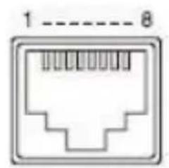 1/EXT 1/EXT | |||||
8. DVIP Configuration Tool
The DVIP Configuration Tool allows users to setup the network setting of the BC-80 HD block camera. Please see following sections for the detail of the DVIP Configuration Tool setting.
8.1 DVIP Configuration Tool Setting
At first, you have to download the DVIP Configuration Tool from Datavideo website's product page to your PC. Moreover, you can also get the DVIP Configuration Tool from your local distributor. After the software download is completed, please follow following steps for setting the DVIP Configuration Tool.
Step1. Connect your PC directly to the DVIP port of the BC-80 camera. If there is more than one BC-80 camera, please connect all the BC-80 cameras to an Ethernet router. Please make assure that the Ethernet router and all connected devices are within the same IP range.
Step2. On the PC, please open the DVIP Configuration Tool by double-clicking the "DVIP_Net_Conf.exe."
8.1.1 User Interface
Step1. After the DVIP Configuration Tool is opened, please select the corrected network interface card in your PC and then click the button "OK".
Note: Please make sure that the selected network interface card is within the same IP range as the connected BC-80 camera or it is impossible for the DVIP Configuration Tool to find the connected DVIP device.
![Select Network Interface f... Network Interfaces [169.254.14L.154] Local Area Connection™ L1 [169.254.14L.154] Local Area Connection™ L1 [169.254.247.81] Local Area Connection™ L3 [162.340.100.101] Ethernet [162.348.1.18] Wi-Fi [127.0.0.] Loopback Pseudo-Interface 1 LOADING ...](/content/2026/05/946741/images/c96cdfe28e445ad9d88610d1e2322ec1a83f698e167e2415a59bfbed31153450.jpg)
Step2. After logging in the interface card, the user will be able to view the device name, MAC address and number of device.
![DVP Network Configuration Tool v10.7 Network Language # datavideo Number of Devices1 HOST-NAMX0631AB [00:07:36:06:31:AB] Name: HOST-NAMX0631AB MAC address 00:07:36:06:31:AB • Using DHCP Mode • Using Fixed IP Mode IP address 192.168.100.122 Mask 255.255.255.0 Gateway 192.168.100.1 Primary DNS 8.8.8.8 Secondary DNS 8.8.4.4 Save](/content/2026/05/946741/images/ace3278ce3ac8b09c355dff5b463f1f07cb473c00b585f86b0fc5beaee2caa4b.jpg)
8.1.2 Device Search
- On the tool bar, users can click the search icon to search for all DVIP devices.
![DVP Network Configuration Tool v1.0.7 Network Language Sew its device datavideo Number of Devices:1 HOST-NAME0431AB [00:07:36:06:31:AB] Name HOST-NAME0631AB MAC address 00:07:36:08:31:AA Using DHCP Mode Using Plan3 IP Mode IP address 192.168.100.122 Mask 255.255.255.0 Gateway 192.168.100.1 Primary DNS 8.8.8.8 Secondary DNS 8.8.4.4 Save](/content/2026/05/946741/images/42b30a8676c9e41551e89e2c6fff7986d02b21755e04efd2b41a9fcf0e580030.jpg)
8.1.3 Clearing Device List
- On the tool bar, users are allowed to clear the device list by clicking the "Device List Clear" button.

8.1.4 Detailed Device Network Information
● After selecting a device in the left column, you will then be able to view each device information on the right, including name, MAC, IP address and etc.
![DVP Network Configuration Tool v1.0.7 Network Language datavideo Number of Devices:1 HOST-NAME0631AB [00:07:36:06:31:AB] Name HOST-NAME0631AB MAC address 00:07:36:06:31:AB Using DHCP Mode Using Fixed IP Mode IP address 192.168.100.122 Mask 255.255.255.0 Gateway 192.168.100.1 Primary DNS 0.0.8.0 Secondary DNS 0.0.4.4 Save](/content/2026/05/946741/images/1d202178992a07e6dd403696adf4184e4f70f14a0d923f08781f324c07768bd6.jpg)
8.1.5 Modify Device Information and Write to Device
- The user is allowed to modify the device information in the right column such as device name, MAC, IP address and etc. Click the Save button to write the information into the device. Right after the Save button is clicked, you will be able to see a prompt message at the top right corner to request for a device reboot for the new settings to become effective.

8.1.6 Switch to Other Network Interface
● To select other network interface cards, click Network Network Card


8.1.7 Language Selection
- On the tool bar, select a language: Traditional Chinese, Simplified Chinese or English
![DVD Network Configuration Toolv1.8.2 Network Language 整體中文 简体中文 English Number of Devices:1 HOST-NAME0631AB [00:07:36:06:31:AB] Name HOST-NAME0631AB MAC address 00:07:36:06:31:AB Using DHCP Mode Using Fixed IP Mode IP address 192.168.100.122 Hack 255.255.255.0 Gateway 192.168.100.1 Primary DNS 8.8.8.8 Secondary DNS 8.8.4.4 Save](/content/2026/05/946741/images/807395c71d466980e2aa575f1881183f3386156d3348bb2ece74de2e8c9733d6.jpg)
9. Firmware Upgrade
1) Copy MB CPU and MB FPGA image files into the root directory of a USB hard drive (<16 GB) and insert it into the USB Upgrade port (You may use a USB extension cord).
2) Open the OSD menu using IR remote control by pressing the MENU button.
3) Browse to => 4: SYSTEM => 4: UPDATE SOFTWARE => 4: UPDATE ALL => YES => ENTER
4) Wait for another five minutes until the following lines appear on the screen - Updated FPGA =>OK - Updated MCPU =>OK The OSD will flash “Write OK/Power ON Again”.
Note: it takes approximately 5-7 minutes to complete the update.
5) Turn off the device by unplugging the power cord. Plug the power cord back into the socket and then turn on the device again.
6) FW Update is complete.
10. Dimensions

natural_image
Technical line drawing of a cylindrical mechanical component with concentric grooves and mounting flanges (no text or symbols)

natural_image
Technical line drawing of a cylindrical mechanical component with mounting flanges and a dimension label (202.05) at the bottom, no readable text or symbols beyond the dimension line.
natural_image
Back view of an electronic device casing with labeled components (no text or symbols visible)
natural_image
Technical line drawing of a rectangular electronic device with heat sinks and ports (no text or symbols)All measurements in millimeters (mm)
- Specifications
| Video | |
| Image Pickup Element | 1/2.8” type Exmor CMOS sensor |
| Effective Picture Elements | Approx. 2.38 Mega pixels |
| Signal System | HDMI & SDI:1080p/59.94/50/29.97/251080i/59.94/50720p/59.94/50 |
| S/N Ratio | 50 dB |
| Min. Illumination | 50%, High Sensitivity ModeColor : 0.75 lx (F1.8, AGC ON, 1/30 sec) |
| Electric Shutter | 1/25 (1/30), 1/50 (1/60),1/75(1/90), 1/100, 1/120(1/125), 1/150(1/180),1/215( 1/250), 1/300(1/350),1/425(1/500), 1/600(1/725),1/1000, 1/1250(1/1500) sec. |
| Gamma Control | Off / Normal / Standard Mode 1-4 |
| Iris Control | Auto / Manual |
| Digital Noise Reductions | 0 – 5 |
| On-Screen Display (OSD) | English |
| White Balance | AWB / MWB / One push WB /Outdoor / Indoor / Fluorescent |
| AGC / Gain Control | Auto / Manual (0 to 28 step)Max. Gain Limit (6 to 28 step) |
| Zoom Ratio | 30x Optical Zoom |
| Mirror | OFF / Horizontal / Vertical / H+V |
| Color Bar | On / Off (Full Bar) |
| Focus Mode | Auto / Manual |
| Day & Night (IR) | Auto / Color / BW |
| Lens | |
| Lens Type | 30x Optical Zoom |
| Focal Length | F=4.3 mm (WIDE) to 129 mm (TELE)F1.6 to F4.7 |
| Angle of View (Horizontal) | Approx. 63.7 degrees (WIDE END) / 2.3 degrees (TELE END) |
| Filter | M52.0 x 0.75 Thread with UV Protection |
| RoHS | Compliant |
| Video Output | |
| Video Output | HDMI (V1.3) x 1HD-SD-SDI x 1 |
| Control | |
| Protocol | VISCA / DVIP Protocol |
| Remote Control | RS-422 & DVIP by RJ-45 interface |
| F/W Update | USB 2.0 |
| IR Control | One IR controller |
| Others | |
| Operating Temperature | 0°C ~ 40°C (32°F~104°F) |
| Storage Temperature | - 10°C ~ 60°C (14°F~140°F) |
| Operating Humidity: | 10% to 80% (non-condensing) |
| Power | DC 12V 1A |
| Power Consumption | 10W |
| Dimensions (W x H x D) | 71.4 x 82.6 x 202.05(mm)(without Tripod mount adapter)71.4 x 95.2 x 202.05(mm) (with Tripod mount adapter) |
| Weight | 0.7kg |
| Size of Screw Holes for Tripod | Use hot shoe mount |
Service & Support
It is our goal to make your products ownership a satisfying experience. Our supporting staff is available to assist you in setting up and operating your system. Please refer to our web site www.datavideo.com for answers to common questions, support requests or contact your local office below.

Please visit our website for latest manual update. https://www.datavideo.com/product/BC-80
datavideo
www.datavideo.com

@DatavideoUSA @DatavideoIndia2016
@DatavideoEMEA @Datavideojapan
@DatavideoTaiwan @DatavideoLatam
@DatavideoAsia @DatavideoBrasil

@Datavideo
@Datavideo_EMEA
@Datavideo Taiwan

@DatavideoUSA
@DVTWDVCN

@DatavideoUSA
@DatavideoEurope
All the trademarks are the properties of their respective owners.
Datavideo Technologies Co., Ltd. All rights reserved 2020
- Instruction Manual
- Table of Contents
- Disclaimer of Product & Services
- FCC Compliance Statement
- Warnings and Precautions
- Warranty
- Standard Warranty
- Three Year Warranty
- Disposal
- For EU Customers only - WEEE Marking
- Introduction
- Features
- Connections
- Front View
- SDI Output
- HDMI Output
- RS-422 Control Port
- 12V DC Power IN
- Power Switch
- Power LED Indicator
- DVIP Control Port
- Firmware Upgrade Port
- DIP Switch
- IR Remote Control
- OSD Menu Options
- [MAIN MENU]
- DIP Switch Settings
- RMC-180 PTZ Camera Control Unit
- Direct Connection to Camera
- DVIP Configuration Tool
- DVIP Configuration Tool Setting
- User Interface
- Device Search
- Clearing Device List
- Detailed Device Network Information
- Modify Device Information and Write to Device
- Switch to Other Network Interface
- Language Selection
- Firmware Upgrade
- Dimensions
- Service & Support
- datavideo
Brand : DataVideo
Model : BC-80
Category : Camcorder