
LX-MU800Z - Video projector CANON - Free user manual and instructions
Find the device manual for free LX-MU800Z CANON in PDF.


| Product Type | Video Projector |
| Brand | Canon |
| Model | LX-MU800Z |
| Resolution | WUXGA (1920 x 1200) |
| Brightness | 8000 lumens |
| Contrast Ratio | 3000:1 |
| Light Source | Laser |
| Light Source Life | 20,000 hours |
| Lens Shift | Vertical: ±50%, Horizontal: ±10% |
| Keystone Correction | Vertical: ±30°, Horizontal: ±30° |
| Dimensions (W x H x D) | 500 x 200 x 400 mm |
| Weight | 15.0 kg |
| Power Consumption | 600 W (max) |
| Power Supply | AC 100-240 V, 50/60 Hz |
| Connectivity | HDMI (2), DVI-D, VGA, USB, RS-232, Ethernet |
| Noise Level | 35 dB (normal mode) |
| Operating Temperature | 0°C to 40°C |
| Maintenance | Clean air filter every 1000 hours, replace light source at end of life |
| Safety | Laser class 1, do not stare into beam |
| Spare Parts | Air filter kit, light source unit, remote control |
Frequently Asked Questions - LX-MU800Z CANON
User questions about LX-MU800Z CANON
0 question about this device. Answer the ones you know or ask your own.
Ask a new question about this device
Download the instructions for your Video projector in PDF format for free! Find your manual LX-MU800Z - CANON and take your electronic device back in hand. On this page are published all the documents necessary for the use of your device. LX-MU800Z by CANON.
USER MANUAL LX-MU800Z CANON
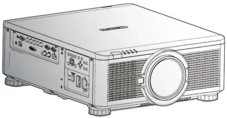
MULTIMEDIA PROJECTOR
LX-MU800Z / LX-MU600Z
User's Manual
natural_image
Line drawing of a projector with front panel and control buttons (no text or symbols)Trademark Recognition

Kensington is a U.S. registered trademark of ACCO Brand Corporation with issued registrations and pending applications in other countries throughout the world.

HDMI, the HDMI Logo, and High-Definition Multimedia Interface are trademarks or registered trademarks of HDMI Licensing LLC in the United States and other countries.

HDBaseT is a trademark of HDBaseT Alliance.

Crestron Connected and the Crestron logo are trademarks or registered trademarks of Crestron Electronics, Inc. in the United States and other countries or both.
All other product names used in this manual are the properties of their respective owners and are acknowledged.
Copyright Notice
Please note that enlarging or reducing the size of an image for commercial purposes or public presentation may infringe on the legally protected copyright or the copyright holder of the original material.
About Trademarks
■ Ethernet is a registered trademark of Xerox Corporation.
■ Microsoft, Windows, Windows Vista, Windows 7, Windows 8 and Aero are registered trademarks or trademarks of Microsoft Corporation in the United States and / or other countries.
■ Mac, Mac OS and Macintosh are trademarks of Apple Inc., registered in the United States and / or other countries.
■ HDMI, the HDMI logo and High-Definition Multimedia Interface are trademarks or registered trademarks of HDMI Licensing, LLC.
■ PJLink is a registered trademark, or an application has been submitted for trademark, in Japan, the United States and / or other countries or regions.
■ AMX is a trademark of AMX Corporation.
■ Crestron ^® , Crestron RoomView ^® , and Crestron Connected ^™ are registered trademarks of Crestron Electronics, Inc.
Ensure Network Security
Take measures to ensure network security. Note that Canon is not liable in any way for direct or indirect loss from network security incidents, such as unauthorized access.
Examples of Security Measures
■ Use in an intranet environment.
■ Assign a private IP address.
■ Use behind a firewall.
■ Change passwords regularly.
♦ Projector Installation Notice
- Allow at least 50 cm clearance around the exhaust vent.
■ Ensure that the intake vents do not recycle hot air from the exhaust vent.
■ When operating the projector in an enclosed space, ensure that the surrounding air temperature within the enclosure does not exceed operation temperature while the projector is running, and the air intake and exhaust vents are unobstructed.
■ Do not block the air intake or air outlet of the cooling fan. If the air intake or air outlet is blocked, heat cannot be released from inside the projector, which may cause malfunction.
♦ Verify Installation Location
■ Turn on Altitude Mode when located in high altitude areas.
■ When installation the bracket, make sure the weight limit is not exceed and firmly secured.
■ Avoid installing at high temperature, insufficient cooling and heavy dust locations.
- Keep your product away from fluorescent lamps to avoid malfunction caused by IR interference.
■ The power cord and signal cable should be connected before power on the projector. During the projector starting and operating process, DO NOT insert or remove the signal cable or the power cord to avoid damaging the projector.
♦ Cooling notes
Exhaust vent
■ Exhaust vent location should not be in front of the lens of other projector to avoid causing illusions.
- Keep the exhaust vent at least 50 cm away from the inlets of other projectors.
Air intake vent
■ Make sure there is no object blocking air intake vent within 30 cm.
- Keep the air intake vent away from other heat sources.
■ Do not install the projector in a location that is damp, or where there is a lot of dust, oily smoke or tobacco smoke.
Power Safety
■ Only use the supplied power cord.
■ Do not place anything on the power cord. Place the power cord where it will not be in the way of foot traffic.
■ The wall outlet must be able to meet the power demands of the device.
About this manual
This manual is intended for qualified technicians / end users and describes how to install and operate the DLP projector. Wherever possible, relevant information such as an illustration and its description has been kept on one page. It is suggested that you only print sections that are relevant to your needs.
Table of Contents
Safety Instructions ....1
Getting Started....17
Packing Checklist....17
Views of Projector Parts 18
Front View....18
Rear View....19
Bottom View 19
Terminals....20
Control Panel 21
Power Panel 22
Remote Control 23
Remote Control Operating Range....25
Setting the Remote ID to the Projector....26
Clearing the Remote ID....26
Projector and Remote Control Buttons....26
Setup and Operation 27
Inserting the Remote Control Batteries 27
Installing the Lens 28
Using the Anti-theft Screw for Lens....29
Projector Parts and Functions....29
Location of Laser Aperture 29
Interlock Switches 30
Precaution for Installing the Projector 31
Projector Installation and Setup 31
Cautions for Ventilation 31
Portrait Projection (Vertical Orientation)....32
Connecting the Projector....33
Connecting to the PC....33
Connecting to the AV Equipment 33
Connecting to the Control Devices....34
Connecting to the Screen Trigger 34
Connecting to the External HDBaseT Transmitter 35
Connecting to the 3G-SDI....35
Connecting to the Extended Monitor....36
Starting and Shutting down the Projector....36
Adjusting the Projector Level....37
Adjusting the Focus and Zoom....38
Adjust the Keystone 38
Adjusting the Lens Shift....38
Vertical Lens Shift 39
Horizontal Lens Shift 40
Horizontal Lens Shift for LX-IL01UW (Ultra Wide Zoom Lens) 41
On-Screen Display (OSD) Menu Settings....42
OSD Menu Controls 42
Navigating the OSD 42
Setting the OSD Language 43
OSD Menu Overview....44
DISPLAY Menu 48
3D Menu....49
PICTURE Menu....50
Color Menu....51
VGA Setup Menu 52
LASER Menu....53
ALIGNMENT Menu 54
Lens Control Menu....55
Lens Memory Menu 56
Geometry Menu 57
Maintenance and Security 80
Replacing the Projection Lamp 80
Cleaning the Projector....82
Cleaning the Cabinet....82
Cleaning the Lens 82
Using the Kensington ^® Lock....83
Ceiling Attachment Installation....84
Parts Lineup 84
Supplied Parts 84
Extension Pipe RS-CL08 / RS-CL09 (Optional) 85
Mounting Position....85
Installation Dimensions 85
Distance from Ceiling to Lens Center (ℓ) 86
Ceiling-mount Bracket 86
Assembly and Installation....86
Installation to Flat and Level Ceiling 86
Installation to a High Ceiling 88
Adjust the Projection Angle 91
Adjust the Horizontal Projection Angle 91
Adjust the Vertical Projection Angle 91
Adjust the Screen Inclination....91
Specifications 92
RS-CL15 92
Troubleshooting 93
Image Problems 93
Remote Control Problems....93
Having the Projector Serviced....93
Specifications 94
Product Specifications....94
Projector Dimensions 95
Forholdet mellem Image Size or projekteringsdistance 96
Lens Series 98
LED Indicator Status 99
Power LED Indicator 99
Status LED Indicator 99
Light LED Indicator....99
Temperature LED Indicator....99
Supported Signal Input Timing 100
Computer 100
3D Signal Input Mode....100
3G-SDI 101
Notes for Projection Mode....102
Appendix 103
Canon LX-MU800Z / LX-MU600Z User Commands 103
Interface and Requirements (Ver 1.0)....103
System Operation Commands 103
System Operation Command....103
Safety Instructions
Before installing and operating the projector, read this manual thoroughly.
This projector provides many convenient features and functions. Operating the projector properly enables you to manage those features and maintain it in good condition for many years to come.
Improper operation may result in not only shortening the product life, but also malfunctions, fire hazards, or other accidents.
If your projector does not seem to be operating properly, read this manual again, check operations and cable connections, and try the solutions in the “Troubleshooting” section in the user’s manual. If the problem still persists, contact the Canon Customer Support Center.

CAUTION
RISK OF ELECTRIC SHOCK DO NOT OPEN


THIS SYMBOL INDICATES THAT DANGEROUS VOLTAGE CONSTITUTING A RISK OF ELECTRIC SHOCK IS PRESENT WITHIN THIS UNIT.

THIS SYMBOL INDICATES THAT THERE ARE IMPORTANT OPERATING AND MAINTENANCE INSTRUCTIONS FOR THIS UNIT IN THE USER'S MANUAL.

THIS SYMBOL INDICATES THAT THERE IS A POTENTIAL HAZARD OF EYE EXPOSURE TO LASER RADIATION UNLESS THE INSTRUCTIONS ARE CLOSELY FOLLOWED.
CAUTION
Not for use in a computer room as defined in the Standard for the Protection of Electronic Computer / Data Processing Equipment, ANSI / NFPA 75.
Copyright notice
Please note that enlarging or reducing the size of an image for commercial purposes or public presentation any infringe on the legally protected copyright or the copyright holder of the original material.
About Trademarks
■ Ethernet is a registered trademark of Xerox Corporation.
■ Microsoft, Windows, Windows XP, Windows Vista, Windows 7, Windows 8 and Aero are registered trademarks or trademarks of Microsoft Corporation in the United States and / or other countries.
■ Mac, Mac OS and Macintosh are trademarks of Apple Inc., registered in the United States and / or other countries.
■ HDMI, the HDMI logo and High-Definition Multimedia Interface are trademarks or registered trademarks of HDMI Licensing, LLC.
■ PJLink is a registered trademark, or an application has been submitted for trademark, in Japan, the United States and / or other countries or regions.
■ Crestron ^® , Crestron RoomView ^® , and Crestron Connected ^™ are registered trademarks of Crestron Electronics, Inc.
Safety Precautions
WARNING:
■ THIS APPARATUS MUST BE GROUNDED.
■ TO REDUCE THE RISK OF FIRE OR ELECTRIC SHOCK, DO NOT EXPOSE THIS APPLIANCE TO RAIN OR MOISTURE.
This projector produces intense light from the projection lens. Do not stare directly into the lens, otherwise eye damage could result. Be especially careful that children do not stare directly into the beam.
■ Install the projector in a proper position. Otherwise it may result in a fire hazard.
■ Do not cover the ventilation slots on the projector. Heat build-up can reduce the service life of your projector, and can also be dangerous.
■ If the projector is unused for an extended time, unplug the projector from the power outlet.
■ Do not project the same image for a long time.
An afterimage may remain on the DMD panel due to the characteristics of the panel of the projector.
Caution on Hanging from the Ceiling
When hanging the projector from the ceiling, clean the air intake vents and top of the projector periodically with a vacuum cleaner. If you leave the projector unclean for a long time, the cooling fans can be clogged with dust, and it may cause a breakdown or a trouble.
DO NOT SET THE PROJECTOR IN GREASY, WET, OR SMOKY CONDITIONS SUCH AS IN A KITCHEN TO PREVENT A BREAKDOWN OR A DISASTER. IF THE PROJECTOR COMES IN CONTACT WITH OIL OR CHEMICALS, IT MAY BECOME DETERIORATED.
♦ READ AND KEEP THIS MANUAL FOR LATER USE.
All the safety and operating instructions should be read before beginning to operate the product.
Read all of the instructions given here and retain them for later use. Unplug this projector from the AC power supply before cleaning. Do not use liquid or aerosol cleaners on the projector. Use a damp cloth for cleaning.
Follow all warnings and instructions marked on the projector.
For added protection of the projector during a lightning storm, or when it is left unattended or unused for long periods of time, unplug it from the wall outlet. This will prevent damage due to lightning and power surges.
Do not expose this unit to rain or use near water. For example, in a wet basement, near a swimming pool..., etc.
Do not use attachments not recommended by the manufacturer as they may result in hazards.
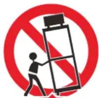
Do not place this projector on an unstable cart, stand, or table. The projector may fall, causing serious injury to a child or adult, and serious damage to the projector. Use only with a cart or stand recommended by the manufacturer, or sold with the projector. For wall or shelf mounting, use a tool such as a mounting kit to secure the projector.
An appliance and cart combination should be moved with care.
Sudden stops, excessive force, and uneven surfaces may cause the appliance and cart combination to overturn.
Slots and openings in the rear and front of the cabinet are provided for ventilation, to insure reliable operation of the equipment and to protect it from overheating.
natural_image
Symbolic icon of a person pushing a ladder under a red prohibition sign (no text or numbers present)The openings should never be covered with cloth or other materials, and the bottom opening should not be blocked by placing the projector on a bed, sofa, rug, or other similar surface. This projector should never be placed near or over a radiator or heat register.
This projector should not be placed in a built-in installation such as a book case unless proper ventilation is provided.
Never push objects of any kind into this projector through cabinet slots as they may touch dangerous voltage points or short out parts that could result in a fire or electric shock. Never spill liquid of any kind onto the projector.
Do not install the projector near the ventilation duct of air-conditioning equipment.
This projector should be operated using only the type of power source indicated on the marking label. If you are not sure of the type of power supplied, contact the local power company.
Do not overload wall outlets and extension cords as this can result in fire or electric shock. Do not allow anything to rest on the power cord. Do not locate this projector where the cord may be damaged by people walking on it.
Do not attempt to service this projector yourself as opening or removing covers may expose you to dangerous voltages or other hazards. Refer all servicing to qualified service personnel.
Unplug this projector from the wall outlet and refer servicing to qualified service personnel under the following conditions:
- When the power cord or plug is damaged or frayed.
- If liquid has been spilled into the projector.
- If the projector has been exposed to rain or water.
- If the projector does not operate normally after following the operating instructions. Adjust only those controls that are covered in the operating instructions as improper adjustment of other controls may result in damage and will often require extensive work by a qualified technician to restore the projector to normal operating condition.
- If the projector has been dropped or the cabinet has been damaged.
- When the projector exhibits a distinct change in performance-this indicates a need for servicing.
When replacement parts are required, be sure the service technician uses replacement parts specified by the manufacturer that have the same characteristics as the original parts. Unauthorized substitutions may result in fire, electric shock, or injury.
Upon completion of any service or repairs to this projector, ask the service technician to perform routine safety checks to determine that the projector is in safe operating condition.
Light Module
■ A light module containing multiple laser diodes is equipped in the product as the light source.
These laser diodes are sealed in the light module. No maintenance or service is required for the performance of the light module.
■ End user is not allowed to replace the light module.
■ Contact qualified distributor for light module replacement and further information.
Laser Safety Precautions
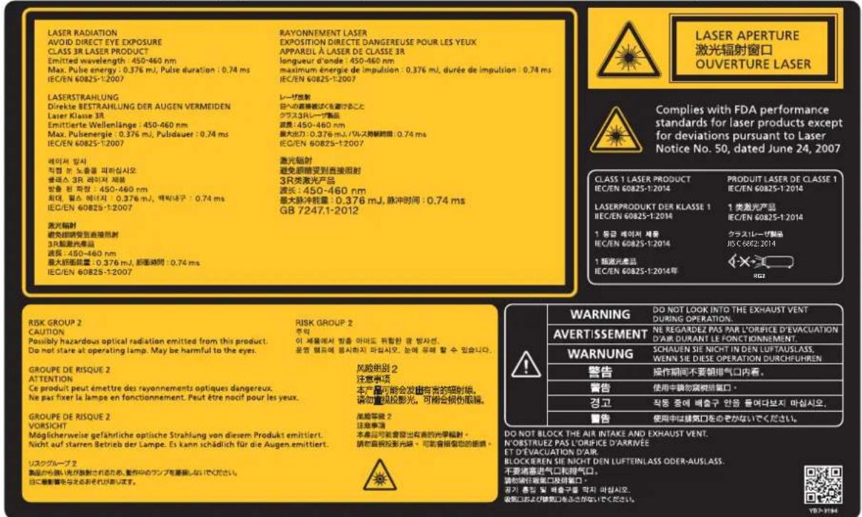
This Product is designated as IEC/EN60825-1: 2007 Class 3R during all procedures of operation.
This Product is designated as IEC60825-1:2014 Class 1 during all procedures of operation.
■ Complies with FDA performance standards for laser products except for deviations pursuant to Laser Notice No. 50, dated June 24, 2007.
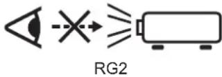
This product is designed as IEC 62471-5:2015 Risk Group 2 during all procedures of operation.

Caution:
■ LASER LIGHT - AVOID DIRECT EYE EXPOSURE.
■ Do not point laser or allow laser light to be directed or reflected toward other people or reflect objects.
■ Direct or scattered light can be hazardous to eyes.
■ There is a potential hazard of eye exposure to laser radiation if the included instructions as not followed.
■ The Laser module is equipped in this product. Use of controls or adjustments or performance of procedures other than those specified herein may result in hazardous radiation exposure.
Laser Parameters:
Blue Laser Diode Wavelength: 450nm - 460nm
Mode of Operation: Pulsed, due to frame rate
Pulse width: 0.74ms
Pulse repetition rate: 240Hz
Maximum laser energy: 0.376mJ
Total internal power: 240W
Apparent source size: >10mm, at lens stop
Divergence: >100 mili Radian
AC Power Cord Requirement
The AC Power Cord supplied with this projector meets the requirements for use in the country you purchased it.
AC Power Cord for the United States and Canada:
The AC Power Cord used in the United States and Canada is listed by the Underwriters Laboratories (UL) and certified by the Canadian Standard Association (CSA).
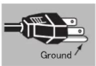
The AC Power Cord has a grounding-type AC line plug. This is a safety feature to ensure the plug fits into the power outlet. Do not try to tamper with this safety feature. Should you be unable to insert the plug into the outlet, contact your electrician.
THE SOCKET-OUTLET SHOULD BE INSTALLED NEAR THE EQUIPMENT AND EASILY ACCESSIBLE.
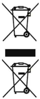
Only for European Union and EEA (Norway, Iceland and Liechtenstein)
These symbols indicate that this product is not to be disposed of with your household waste, according to the WEEE Directive (2012/19/EU), the Battery Directive (2006/66/EC) and/or national legislation implementing those Directives. If a chemical symbol is printed beneath the symbol shown above, in accordance with the Battery Directive, this indicates that a heavy metal (Hg = Mercury, Cd = Cadmium, Pb = Lead) is present in this battery or accumulator at a concentration above an applicable threshold specified in the Battery Directive. This product should be handed over to a designated collection point, e.g., on an authorized one-for-one basis when you buy a new similar product or to an authorized collection site for recycling waste electrical and electronic equipment (EEE) and batteries and accumulators. Improper handling of this type of waste could have a possible impact on the environment and human health due to potentially hazardous substances that are generally associated with EEE. Your cooperation in the correct disposal of this product will contribute to the effective usage of natural resources.
For more information about the recycling of this product, please contact your local city office, waste authority, approved scheme or your household waste disposal service or visit http://www.canon-europe.com/weee, or http://www.canon-europe.com/battery.
Voltage Selection
The VOLTAGE SELECT switch must be set to match the power supply you are using:
| Voltage of Power Supply Used Position | of VOLTAGE SELECT switch |
| AC 100V InletFor LX-MU800Z/LX-MU600Z (U) andLX-MU800Z/LX-MU600Z (J) | VOLTAGE SELECT交流电压选择200-240 V~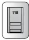 100-130 V~ 100-130 V~ |
| AC 220V (single phase) InletFor LX-MU800Z/LX-MU600Z (E) andLX-MU800Z/LX-MU600Z (CH) | VOLTAGE SELECT交流电压选择200-240 V~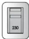 100-130 V~ 100-130 V~ |
Caution:
Improper selection of the switch could damage the projector.
Federal Communication Commission Notice
This device complies with Part 15 of the FCC Rules. Operation is subject to the following two conditions:
- This device may not cause harmful interference, and
- This device must accept any interference received, including interference that may cause undesired operation.
Note: This equipment has been tested and found to comply with the limits for a Class A digital device, pursuant to Part 15 of the FCC Rules.
These limits are designed to provide reasonable protection against harmful interference when the equipment is operated in a commercial environment. This equipment generates, uses, and can radiate radio frequency energy and, if not installed and used in accordance with the instruction manual, may cause harmful interference to radio communications.
Operation of this equipment in a residential area is likely to cause harmful interference in which case the user will be required to correct the interference at his own expense.
The cable with a ferrite core provided with the projector must be used with this equipment in order to comply with Class A of the FCC Rules.
Use of a shielded cable is required to comply with Class A of FCC Rules.
Do not make any changes or modifications to the equipment unless otherwise specified in the instructions. If such changes or modifications should be made, you could be required to stop operation of the equipment.
Warning:
This is a class A product. In a domestic environment this product may cause radio interference in which case the user may be required to take adequate measures.
The cable with a ferrite core provided with the projector must be used with this equipment in order to comply with Class A.
Use of a shielded cable is required to comply with Class A.
Product Labels
Manufacturer's ID Label
LX-MU800Z
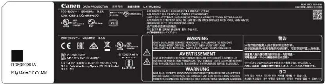
Hazard Warning Symbol, Aperture Label, Certification Statement Label and Explanatory Label
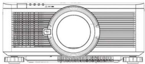
natural_image
Technical line drawing of a projector with ventilation grilles and fan (no text or symbols)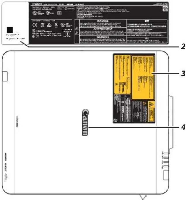
| Item | Description |
| 1 | Manufacturer's ID Label on the body of the projector. |
| 2 | Serial number and the date of production Label on the body of the projector. |
| 3 | Certification Statement Label and Caution Label on the body of the projector. |
| 4 | Brand Name Plate Label on the body of the projector. |
LX-MU600Z
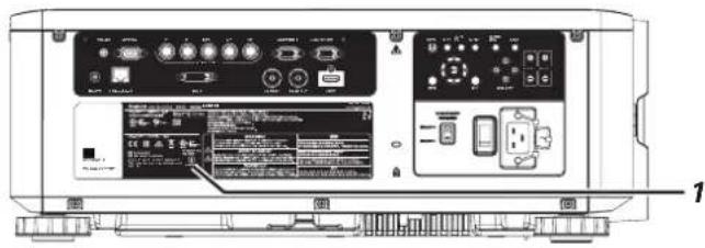
natural_image
Technical line drawing of a projector fan with ventilation grilles and mounting base (no text or symbols)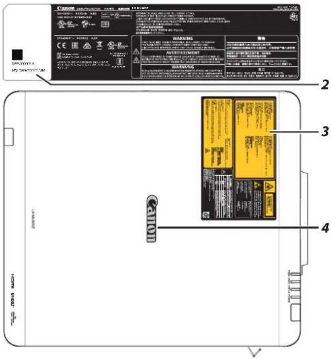
| Item | Description |
| 1 | Manufacturer’s ID Label on the body of the projector. |
| 2 | Serial number and the date of production Label on the body of the projector. |
| 3 | Certification Statement Label and Caution Label on the body of the projector. |
| 4 | Brand Name Plate Label on the body of the projector. |
Safety Symbols in this Manual
This section describes the safety symbols used in this manual. Important projector safety information is identified by the following symbols. Always observe the safety information by these symbols.
Denotes the risk of death or serious injury from improper handling if the information is not observed. To ensure safe use, always observe this information.

Denotes the risk of injury from improper handling if the information is not observed. To ensure safe use, always observe this information.
Precautions for Use
As this section contains important safety-related information, be sure to read the following carefully beforehand in order to use your projector correctly and safely.

Warning
During installation, keep the projector plug easily accessible so that the projector can be unplugged immediately if necessary, or keep a circuit breaker within reach.
If the following situations occur, turn the power off, remove the power plug from the power outlet and contact the Canon Customer Support Center. Failure to do so could cause a fire or result in an electric shock.
■ If smoke is emitted
■ If an unusual smell or noise is emitted
■ If water or other liquid has entered the projector
■ If metal or any other foreign material has entered the projector
■ If the projector is knocked over or dropped and the cabinet is damaged
Pay attention to the following points for handling the power cord. Failure to do so may cause a fire, electric shock or personal injury.
■ Do not place any objects on the power cord and do not allow it to become trapped under the projector.
■ Do not cover the power cord with a carpet.
■ Do not modify or excessively bend, twist, pull, wind, or bundle the power cord.
- Keep the power cord away from heaters and other sources of heat.
■ Do not use a damaged power cord. If the power cord is damaged, purchase a replacement from your dealer.
■ The power cord included with this projector is for use exclusively with this product. Do not use this cord for other products.
■ Be sure to connect the ground wire of the power cord to ground.
■ Be sure to connect the ground wire before connecting the power plug to the outlet. Also when you disconnect the ground wire, be sure to unplug the power plug from the outlet beforehand.

Warning
Pay attention to the following points regarding the power source, power plug and handling of the connector. Failure to do so may cause a fire, electric shock or personal injury.
- Do not use any power source with a voltage other than the voltage indicated (AC 100–240 V).
- Do not pull the power cord and be sure to hold the power plug or connector when removing. Incorrect handling may damage the power cord.
■ Do not insert any metal objects into the contact parts of the power plug or connector.
■ Do not remove the power plug or connector with wet hands. - Insert the power plug and connector securely up to the base. Additionally, do not use a damaged power plug or an outlet that is loose.
- When using an extension cord, do not exceed the cord's rated capacity.
■ Periodically inspect the power plug and outlet and remove any dust or dirt from between the plug and the outlet.
Installation and Handling Precautions
Pay attention to the following points regarding installation and handling of the projector. Failure to do so may cause a fire, electric shock or personal injury.
■ Do not use the projector where it might get wet, such as outdoors or by bathtubs or showers.
■ Do not place containers containing a liquid on top of the projector.
■ Do not touch the projector itself, the power cord, or the cable if lightening strikes.
- Do not move the projector until you have switched off the power, removed the power plug from the power outlet and unplugged any other cables.
■ Unplug the projector before cleaning or maintenance.
■ Before installing or replacing a lens unit, make sure to remove the power plug from the outlet. Failure to do so could result in an electric shock or injury.

Warning
Pay attention to the following points regarding installation and handling of the projector. Failure to do so may cause a fire, electric shock or personal injury.
■ Do not remove the cabinet from the projector or disassemble it. The interior of the projector contains high-voltage components as well as parts that are hot. If inspection, maintenance or repair is required, contact the Canon Customer Support Center.
■ Do not disassemble or modify the projector or the remote control.
■ Do not look directly into the exhaust vents during use.
■ Do not insert any object into vents in the projector, such as the air intake vent or exhaust vents.
■ Do not place a pressurized can in front of the exhaust vents. The pressure of the contents of the can may increase due to heat from the exhaust vents and this could result in an explosion.
■ Using the lens shift function the lens in the projector moves up / down / left / right powered by a motor. Do not touch the lens when the lens is moving. Doing so could cause a personal injury.
■ Before replacing the lens unit, make sure the projector is turned off to allow the projector to cool thoroughly. Failure to do so could result in a burn or injury.
■ When cleaning off dust or dirt from the projector lens etc., do not use any kind of spray that is flammable.
■ As strong light beams are emitted while the projector is in use, do not look directly into the projector lens. Doing so could cause an eye injury. Pay particular attention to prevent small children from doing so.
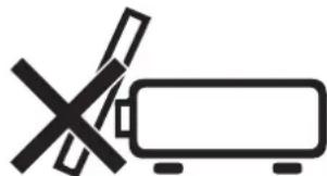
■ When setting the projector on a high surface for projection, be sure the surface is flat and stable.
■ For ceiling mounting precautions, refer to the installation manual included with the ceiling mount (sold separately).
■ When hanging the projector from a ceiling, put the projector down on the floor or a workbench before attaching or replacing the lens unit. Failure to do so could result in parts falling off the projector and may cause an accident or personal injury.

Warning
Precautions for the Batteries of the Remote Control
Pay attention to the following points regarding handling of batteries. Failing to do so could result in a fire or personal injury.
■ Do not heat, short circuit or disassemble the batteries, or place them in a fire.
■ Do not attempt to recharge the batteries that are included with the remote control.
■ Remove the batteries when they are flat or when the remote control will not be used for a long period of time.
■ When replacing the batteries, replace both at the same time. Also, do not use two batteries of a different type at the same time.
- Insert the batteries with the + and - terminals in the correct directions.
If any liquid from inside the batteries leaks out and contacts your skin, be sure to wash the liquid off thoroughly.

Caution
Pay attention to the following points regarding installation and handling of the projector.
If the projector will not be used for a long period of time, be sure to remove the power plug from the power outlet to ensure safety. Failure to do so presents a risk of fire if dust accumulates on the plug or outlet.
■ Parts of the cabinet around and above the exhaust vents may become hot during projection. Touching these areas during operation could cause burns to the hands. Pay particular attention in preventing young children from touching these parts. Additionally, do not place any metal objects around or above the exhaust vents. Due to the heat from the projector, doing so could cause an accident or personal injury.
■ Do not place the projector where it may be exposed to oily smoke or steam, such as near kitchen counters or humidifiers. Doing so may cause fire or electric shock.
- Do not place any heavy objects on top of the projector or sit / stand on it. Pay particular attention to prevent small children from doing so. The projector may be knocked over and this could result in damage or a personal injury.
■ Do not place the projector on an unstable or slanted surface. Doing so may cause the projector to fall or be knocked over and could result in a personal injury.
■ Do not place any objects in front of the lens during projection. Doing so could cause a fire.
■ Presenters in front of the projector should stand where the light does not seem too bright, and where their shadow does not fall on the screen.
Caution for Viewing 3D Content

Caution
Pay attention to the following points when viewing 3D content.
■ Photosensitive patients, patients with heart disease, pregnant women, elderly people, and people with serious illness and/or with a history of epilepsy should not view 3D content.
We advise that you should refrain from viewing 3D content if you are in bad physical condition, need sleep or have been drinking alcohol.
■ Stop watching 3D content if you experience the following symptoms. If you experience such symptom, immediately stop viewing 3D content and take a break until the symptom has subsided.
■ You see doubly-blurred images or you cannot view the image stereoscopically.
■ You feel fatigue or discomfort.
Take breaks when viewing 3D content for an extended period of time. As this may cause eye fatigue. Viewing 3D content for an extended period of time or viewing them from an oblique angle can cause eye strain.
■ Parents should accompany and monitor their children as children cannot properly express discomfort with 3D content viewing. Children who are six year of age or younger should not view 3D content.
■ The optimum 3D viewing distance from the screen is about 3 times of the vertical screen size or more and your eyes should be level with the screen.

Caution
Pay attention to the following points when carrying or transporting the projector.
This projector is a precision instrument. Do not knock it over or subject it to impacts. Doing so may cause a malfunction.
■ When carrying or holding up the projector after attaching the lens unit, be sure not to hold the lens. Doing so may cause damage to the lens unit.
■ Protection of the projector cannot be guaranteed if used packaging or shock-absorbent materials are reused. Fragments from shock-absorbent material may also enter the interior of the projector which could cause a malfunction.
If transportation is necessary, the lens unit should be removed before transporting the projector. If the projector is subjected to excessive impacts during transportation, the lens unit may be damaged. Removal and installation of the lens unit should not be performed by the user. Be sure to have the procedure performed by a qualified technician or contact the Canon Customer Support Center.
■ Disconnect the cables connected to the projector. Carrying the projector while the cables are attached may cause an accident.
■ Retract the adjustable feet before moving the projector. Leaving the feet extended may cause damage.
■ Do not carry or move the projector alone. Have at least one assistant.

Caution
Pay attention to the following points when installing or using the projector.
■ Do not touch the lens with bare hands. Doing so may result in deterioration of image quality.
If the projector is abruptly taken from a cool to a warm location, condensation may form on the lens or mirrors, which may cause a blurred image. Wait until the condensation has evaporated for the image projected to return to normal.
- Do not install the projector in a location where the temperature is high or low. Doing so may cause a malfunction. For guidelines on operating temperatures, see “Product Specifications”.
■ Do not place any objects on top of the projector that may change shape or color due to heat.
■ Do not install the projector near high-voltage electrical power lines or an electrical power source.
■ Do not use the projector on a soft surface such as carpet or sponge mat, etc. Doing so could cause heat to build up inside the projector and this could result in a malfunction.
■ Do not block the air intake or exhaust vents of the cooling fan.
■ Installing the projector in the wrong direction may cause a malfunction or accident. Do not install the projector with one side raised, or with the projector tilted toward the left or right.
■ Install the projector with sufficient space between air intakes and exhaust vents and walls. Failure to do so could cause a malfunction.
■ Do not install the projector in a location that is damp, or where there is a lot of dust, oily smoke or tobacco smoke. Doing so could cause contamination of optical components such as the lens and the mirror and may result in deterioration of image quality.
■ During projection, do not place anything directly in front of the lens.
Doing so may cause burns or a fire. In addition, it may cause the projector to malfunction. To temporarily stop image, please use the BLANK function on the projector. See "BLANK" on page 21.
natural_image
Simple line icon of a battery with a crossed-out X mark (no text or symbols)Caution for Ceiling Attachment

Warning
Make sure the followings when you install and handle the ceiling attachment. Otherwise, it may result in fire, electric shock or injury.
■ Make sure to prepare stable scaffolding when installing the ceiling attachment.
■ Make sure to fully insert the power plug and connectors when connecting the projector. Never use a damaged plug or loosen outlet.
■ Make sure to tighten screws for the ceiling attachment securely and never loosen or remove them.
■ Never look into a lens when adjusting the projection because a high-intensity light is projected from the projector. It may result in eye damage.
■ During projection, never put an object in front of the projector's lens.

Caution
Make sure the followings when you install and handle the ceiling attachment.
■ Make sure to ask the Canon Customer Support Center if you want to install the ceiling attachment. An inappropriate installation may cause an accident.
Packing Checklist
Check that the following items are included:
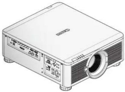
natural_image
Illustration of a projector with ventilation slots and a lens (no text or symbols visible)Projector
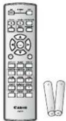
Remote Control (with two AA batteries) (LX-RC01)
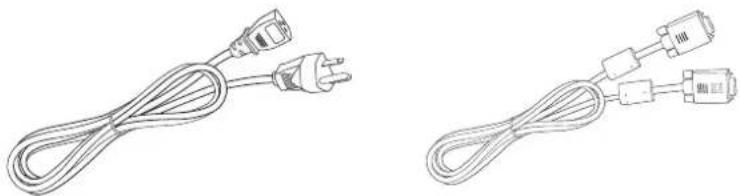
natural_image
Two types of electrical cables shown in line drawings: one with a power plug and cable, the other with two connected connectors (no text or symbols)Power Cord (2.5M/8.2 ft) Computer Cable (1.8M/5.9 ft)
(mini D-sub 15-pin/ mini D-sub 15-pin)
CD-ROM
(This User's manual)
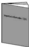
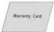
Important Information Warranty Card

Anti-theft Screw for Lens
M4 x 0.7 x 70 mm
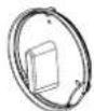
Dust Cap
Contact your dealer immediately if any items are missing, appear damaged, or if the unit does not work. It is recommend that you keep the original packing material should you ever need to return the equipment for warranty service.
Views of Projector Parts
Front View
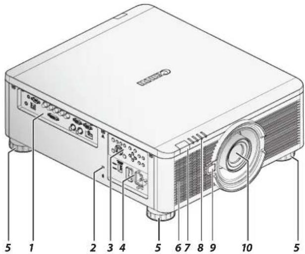
| Item Label Description | ||
| 1 Terminals Use to connect to other devices. | ||
| 2 Kensington Lock Secure to permanent object with a Kensington ^ Lock system. | ||
| 3 Control Panel Use buttons to select or adjust the settings of the projector. | ||
| 4 Power Panel Insert power cord to supply electrical power or select the input voltage. See “Voltage Selection” on page 6. | ||
| 5 | Adjusting Foots | There are 4 adjust foots for adjust the levelness of projection angle. |
| 6 Air Intake Vent Take in air to cool the projector. | ||
| 7 Front IR Receiver Receives IR signal from remote control. | ||
| 8 LED Indicators Shows the status of the projector. | ||
| 9 Lens Release Button Push to change the projector lens. | ||
| 10 | Lens | Projection lens. (Optional) |
Rear View
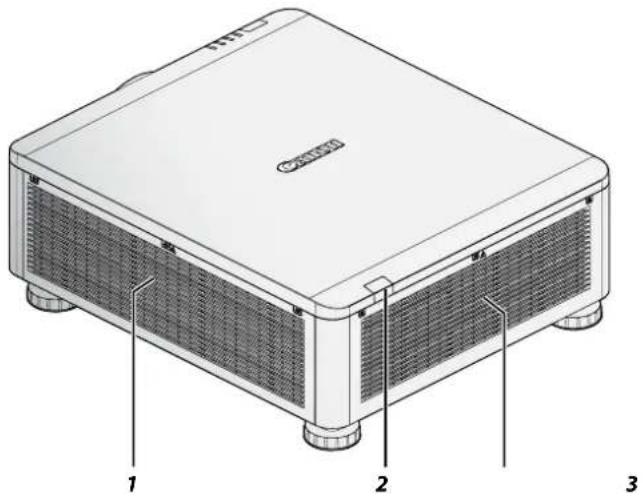
| Item Label Description | |
| 1 Air Intake Vent Take in air to cool the projector. | |
| 2 Rear IR Receiver Receives IR signal from remote control. | |
| 3 Exhaust Vent Heat is discharged from the projector via the exhaust. | |
Bottom View
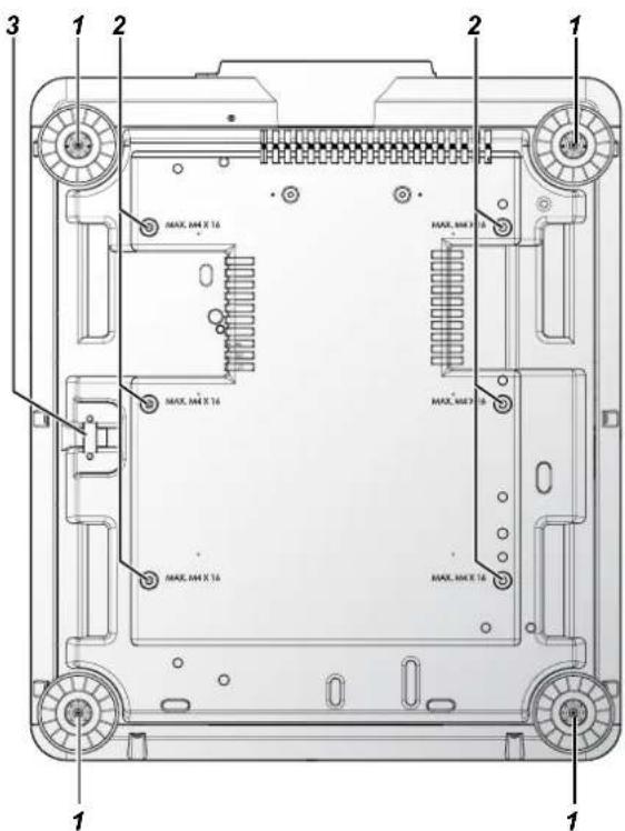
| Item Label Description | ||
| 1 Adjusting Foots Adjust the levelness the projection angle. | ||
| 2 | Fixture Screw Holes | There are six fixture screw holes (M4 x 0.7 x 16mm) at the bottom of projector for ceiling mounting. |
| 3 Security Bar An anti-theft wire cable (not included) can be connected. | ||
Terminals
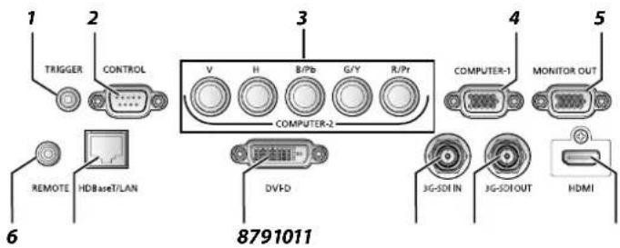
| Item Label Description | ||
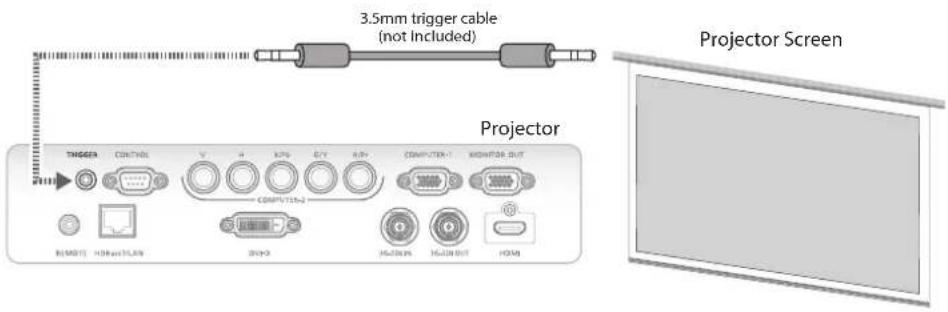
| 1 TRIGGER Provide 12V (+/- 1.5) output for screen operation. | ||
| 2 CONTROL Connect to the PC for system maintenance, projector maintenance and user commands. | ||
| 3 COMPUTER-2 Receives the analog PC signal (Analog PC-2).Connect BNC-type input connectors to the RGB or YPbPr/YCbCr output signal video equipment. | ||
| 4 COMPUTER-1 Receives the analog PC signal.Connect the D-sub 15pin input connector to the RGB output signal. | ||
| 5 MONITOR-OUT Outputs an analog RGB signal (COMPUTER-1) to display an image on an external monitor. | ||
| 6 REMOTE This terminal is used to connect the optional remote control using a cable. Connect a 3.5 mm jack from a wired remote. | ||
| 7 HDBaseT/LAN* Receives HDBaseT input including digital video and audio signals.A LAN cable (shielded twisted pair of CAT5e or higher) can be used for video input.Connects the LAN cable. Used to connect the projector to a network. However, the sound does not come out of the projector. | ||
| 8 DV-D Receives digital PC signal (with DVI-D digital PC). | ||
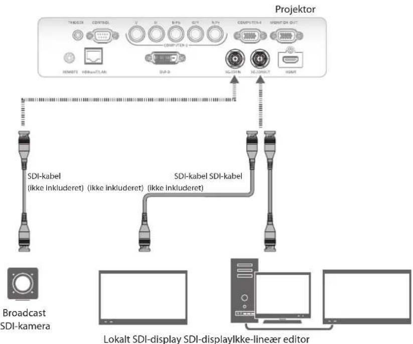
| 9 3G-SDI IN Receives SDI signal. | ||
| 10 | 3G-SDI OUT | Outputs a signal connected with SDI IN terminal. |
| 11 | HDMI | Receives digital video signals (HDMI). |
* Notes on HDBaseT
■ Use a shielded cable rated at CAT5e or higher.
■ Maximum transmission distance is 100 m.
However, maximum transmission distance may be shorter in some environments.
■ Do not use the LAN cable when it is coiled or bundled.
- Inserting or removing the LAN cable during projection may cause noise.
■ Connectivity with all HDBaseT transmitters on the market is not guaranteed.
■ Some HDBaseT transmitters may not enable correct projection when used to connect source equipment to the projector.
Control Panel
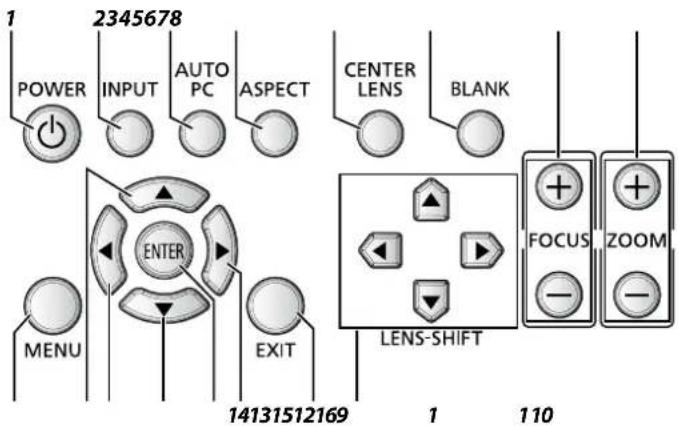
| Item Label Description | ||
| 1 POWER Press to turn on or off the projector. | ||
| 2 INPUT | Press to select the input signal. | |
| 3 | AUTO PC | Press to initiate the automatic synchronization procedure in accordance with the signal from a computer when the analog PC input is selected. |
| 4 ASPECT | Press to change the aspect ratio mode. | |
| 5 CENTER LENS | Press to center the lens (zoom, focus, lens shift).Note:Please center the lens every time after the lens is installed. | |
| 6 BLANK | Press to light or blank the Light output. | |
| 7 FOCUS | Press to adjust the focus of the projected image. | |
| 8 ZOOM | Press to adjust the size of the projected image. | |
| 9 | MENU | Press to display, hide the OSD menu or return the previous OSD menu. |
| 10 | ▲ | Press to select or change settings in the OSD. |
| 11 | ◀ | Press to select or change settings in the OSD. |
| 12 | ▼ | Press to select or change settings in the OSD. |
| 13 | ENTER* | Press to confirm the changed settings. |
| 14 | ▶ | Press to select or change settings in the OSD. |
| 15 | EXIT | Press to exit the OSD menu. |
| 16 | LENS-SHIFT | Press to move the lens up, down, right or left. |
* Lens Adjustment Screen appears when ENTER button is pressed when OSD is not displayed.
Power Panel
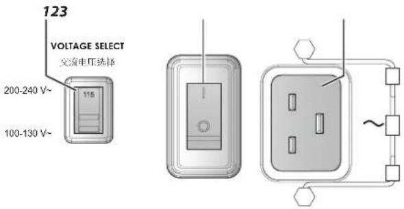
| Item Label Description | |
| 1 VOLTAGE SELECT Slide to select the current input voltage according to the area.See “Voltage Selection” on page 6.Improper selection of the switch could damage the projector.Please contact a qualified technician or the Canon Customer Support Center regarding any unclear points. | |
| 2 Power Switch Turn on or off AC power of the projector. | |
| 3 Power Socket Connect the projector to a wall socket for power.The power socket has a hook for securing the power cord.Do not fail to secure the power cord with the hook. | |
Remote Control
Remote Control Precaution
■ Handle the remote control carefully.
■ Avoid excessive heat and humidity.
■ Do not short, heat, or take apart batteries.
■ Do not throw batteries into fire.
■ Remove the battery if the remote control may not be used for a long time to prevent the damage caused by leaks.
■ Ensure that you have the batteries' polarity (+/-) aligned correctly.
■ Do not use new and old batteries together, or use different types of batteries together.
■ Dispose of used batteries according to your local regulations.
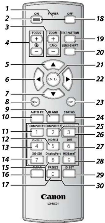
Important:
- Avoid using the projector with bright fluorescent lighting turned on. Certain high-frequency fluorescent lights can disrupt remote control operation.
- Be sure nothing obstructs the path between the remote control and the projector.
- The buttons and keys on the projector have the same functions as the corresponding buttons on the remote control. This user's manual describes the functions based on the remote control.
- Use an exclusive Remote Control (LX-RC01).
| Item Label Description | |
| 1 LED indicator Lights when the key is pressed. | |
| 2 ON Press to turn on the projector. | |
| 3 ZOOM Press to adjust the size of the projected image. | |
| 4 FOCUS Press to adjust the focus of the projected image. | |
| Item Label Description | ||
| 5 ▲ | Press to select or change | settings in the OSD. |
| 6 ◀ | Press to select or change | settings in the OSD. |
| 7 ▼ | Press to select or change | settings in the OSD. |
| 8 MENU | Press to display, hide | the OSD menu or return the previous OSD menu. |
| 9 BLANK | Press to light or blank | the Light output. |
| 10 AUTO | PC Press to initiate the automatic synchronization procedure. | |
| 11 COMPUTER1 | Press to switch input signal to COMPUTER1. | |
| 12 HDMI2 | Press to switch input signal to HDMI. | |
| 13 HDMI1 | ||
| 14 3G | -SDI Press to switch input signal to 3D-SDI. | |
| 15 DisplayPort No function. | ||
| 16 CLEAR | Reset the stored Remote ID. | |
| 17 FREEZE (*1) | Press to freeze the projected image. | |
| 18 OFF | Press to turn off the projector. | |
| 19 | TEST PATTERN | Press to display the test pattern and press again to switch to the next test pattern. PressEXITto return the projected image. |
| 20 LEN | NS-SHIFT Press to move the lens up, down, right or left. | |
| 21 | ENTER (*2) | Press to confirm the changed settings. |
| 22 ▶ | Press to select or change settings in the OSD. | |
| 23 EXIT | Press to exit the OSD menu. | |
| 24 | STATUS | Press to display theSERVICEmenu (OSD). |
| 25 COMPUTER2 | Press to switch input signal to COMPUTER2. | |
| 26 ASPECT | Press to switch to the next aspect ratio setting. | |
| 27 DVI | Press to switch input signal to DVI-D. | |
| 28 | HDBaseT | Press to switch input signal to HDBaseT. |
| 29 ID | SET Press to set the Remote ID. | |
| 30 Numeric buttons | Press numeric to set Control ID or Remote ID. | |
(*1) This function is applicable to 2D signal.
(*2) Lens Adjustment Screen appears when ENTER button is pressed when OSD is not displayed.
Using the Exclusive Remote (LX-RC01) with Wired
To use a wired remote control with the projector.
Use a cable with a 3.5 mm stereo mini jack (not included).
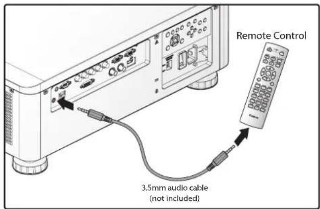
Note:
Infrared operations cannot be performed if a cable is connected to the projector or the remote control.
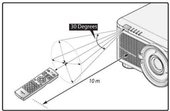
Remote Control Operating Range
The remote control uses infrared transmission to control the projector. Provided you are not holding the remote perpendicular to the sides or the rear of the projector, the remote will function well within a radius of about 10 meters and 30 degrees above or below the projector level. If the projector does not respond to the remote control, move a little closer.
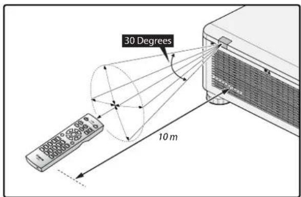
Setting the Remote ID to the Projector
To operate multiple projectors independently, set this ID function.
■ "Remote ID" is for a remote control.
■ "Control ID" is for a projector. See page 76.
- Press the ID SET button for three seconds. The LED indicator on the remote control blinks.
- To designate the Remote ID, press and hold the 2 digit number (01 \~ 99) each button for 1 second at least. The remote control backlight blinks. Once initiated, the ID set procedure allows for ten seconds to complete the process. After ten seconds, you must restart the procedure.
Note:
The factory default is "X / X". "X" means all ID. And the left side is "Control ID". The right side is "Remote ID". See page 76.
Clearing the Remote ID
Press the ID SET and CLEAR for five seconds. The remote control backlight blinks signifying that the ID setting is cleared.
Projector and Remote Control Buttons
The projector can be operated using the remote control or the buttons on the side of the projector. All operations can be carried out with the remote control; however, the buttons on the projector are limited in use.
Setup and Operation
Inserting the Remote Control Batteries
Note:
■ Do not use the old and new batteries or the batteries of different types together.
■ Remove the battery if the remote control may not be used for a long time to prevent the damage caused by leaks.
- Slide the battery cover as illustrated.

natural_image
Diagram of a device interior with a black arrow pointing to a component (no text or symbols present)- Place two AA batteries in the compartment, make sure the polarity in the compartment and batteries are aligned correctly.
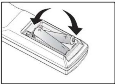
natural_image
Diagram of a battery inside a control casing with arrows indicating rotation (no text or symbols)- Slide the battery cover back.
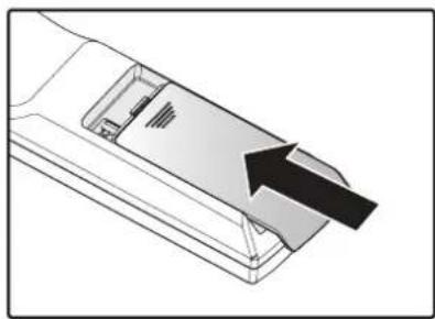
natural_image
Diagram of a mechanical component with an arrow indicating direction (no text or symbols present)Installing the Lens
-
Remove the dust cap.
-
Remove the new lens from its packaging.
-
Remove the lens covers from the rear and front of the new lens. Remove them before continuing.
-
Clean the new lens before installing. Take care when cleaning to prevent scratching the surface of the new lens.
-
Orient the lens so that the arrow on the label pasted on its side is facing upward and push the lens into the lens mount of the unit as far as it will go.
-
Turn the new lens clockwise until and audible Click is heard signifying the new lens is secured and seated correctly.
-
Gently pull on the new lens to ensure it is locked in place. If the new lens does not come off, it is seated correctly.
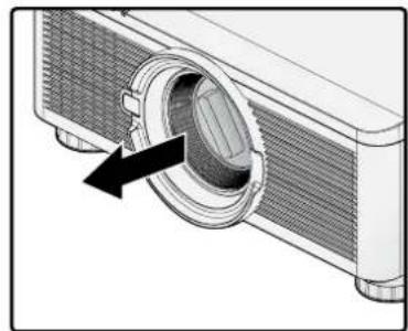
natural_image
Diagram of a projector with a circular aperture and arrow indicating the lens (no text or symbols present)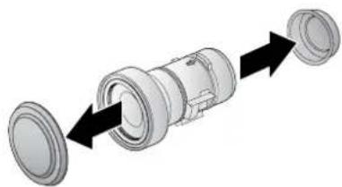
natural_image
Diagram of a mechanical component with two circular parts and directional arrows indicating assembly (no text or symbols)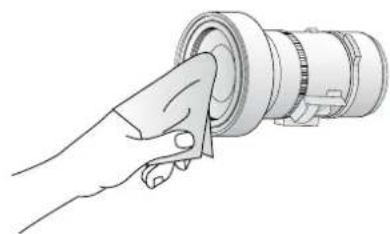
natural_image
Line drawing of a hand holding a cylindrical mechanical component (no text or symbols)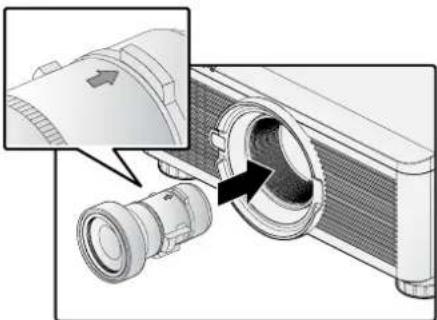
natural_image
Diagram of a projector with a magnified inset showing the lens and internal components (no text or symbols)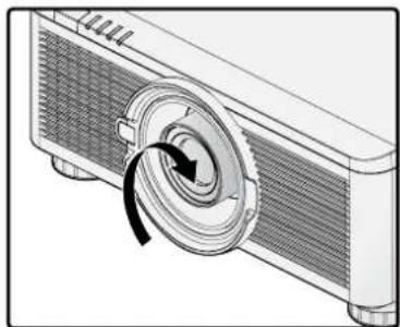
natural_image
Diagram of a projector with a circular dial and arrow indicating rotation (no text or symbols)Note:
■ The projector supports the lens memory function. Perform the memory function every time when you install the lens.
■ Be sure to execute Center Lens after the lens is changed.
■ Refer to User's Manual attached to optional lens as well.
Using the Anti-theft Screw for Lens
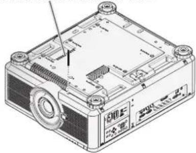
To prevent the accidental removal of the lens, fasten the Anti-theft screw for lens included with the projector to the bottom of the projector.
Anti-theft screw for lens
natural_image
Technical line drawing of a computer chassis with labeled components (no readable text or symbols)Projector Parts and Functions
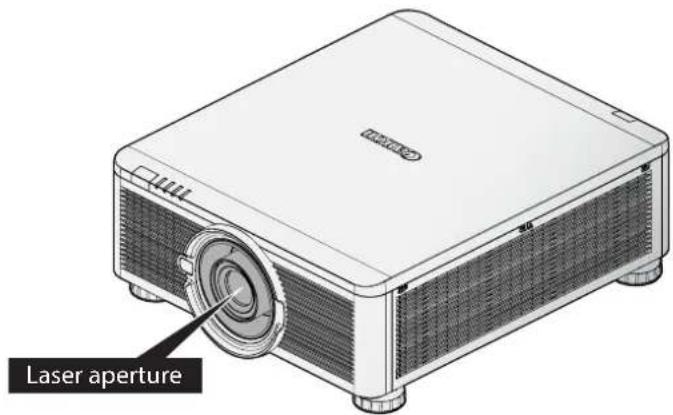
Location of Laser Aperture
Note:
The laser aperture is located as depicted in the following illustration. For your safety, do not stare directly into the laser source. Starring directly into the laser source could permanently damage your eyes.
Interlock Switches
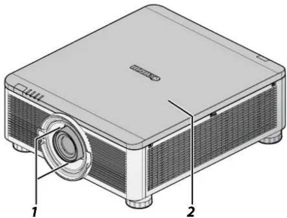
This projector has three (top cover x 1, lens x 2) interlocking switches to protect the user from the unnecessary laser exposure.
natural_image
Illustration of a projector with labeled parts (1 and 2), showing internal structure and mounting points (no text or symbols beyond labels)| Item Description | |
| 1 The | lens alarm function automatically powers off the projector if the lens is removed or not installed correctly. |
| 2 | The intruder alarm function automatically powers off the projector if the top cover is removed. |
Precaution for Installing the Projector
The high quality display from the project is only available when the projector is correctly installed. Generally, the light source facing the screen should be reduced or eliminated as much as possible. The contrast of the image will be obviously reduced if the light directly shines on the screen, such as the beam from windows or the other lighting illumination on the image. The image may become faded and not bright.
Projector Installation and Setup
The available installation options are available as follows:
■ Front Table: Install the projector on the table and project the image forward.
■ Rear Table: Install the image behind the screen and project onto the screen.
■ Front Ceiling: Mounting the projector on the ceiling and project the image forward.
■ Rear Ceiling: Mounting the projector on the ceiling behind the screen and project onto the screen.
Cautions for Ventilation
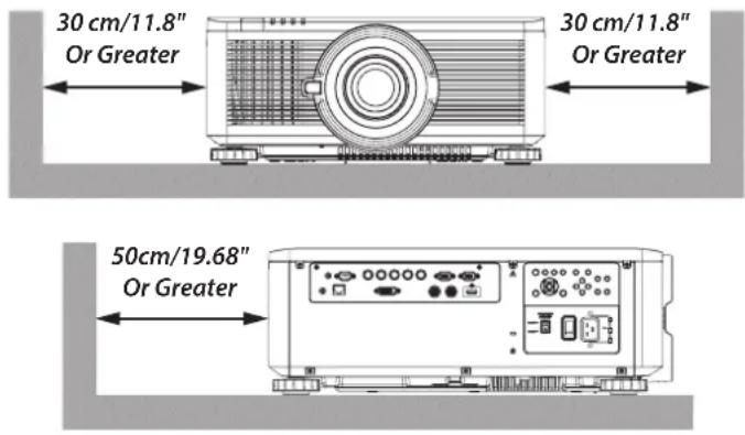
The product is a high-brightness projector. The intake are located on the front and right sides to provide sufficient air for cooling. The projector has two vents on the back for cool air discharging. When installing, make sure the intake and outlet vents meet the required clearance to allow for the proper cooling requirements of the system. At least 30cm around the intake and 50cm around the vent should be clear.
Note:
■ Inadequate cooling may cause the projector to stop operations due to overheating.
■ Overheating may shorten the life of components or laser.
■ The intake and outtake vents should not be obstructed to prevent overheating.
Portrait Projection (Vertical Orientation)
The projector can be installed vertically to display computer images in portrait orientation.
Notes, when installing the projector vertically.
- Allow at least 30 cm(11.8") clearance around the air intake vent.
■ Prepare an exclusive stand (not included).
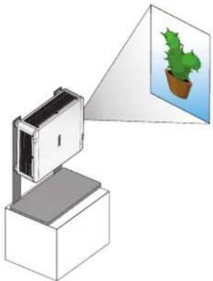
natural_image
Illustration of a device emitting a light beam to a potted plant, no text or symbols presentNote:
Using the projector in the following situation may accelerate the deterioration of optical parts.
■ When the projector is installed on which projection lens faces downward.
■ When the air intake vent of the projector side faces downward in the portrait projection.
Connecting the Projector
Connecting to the PC
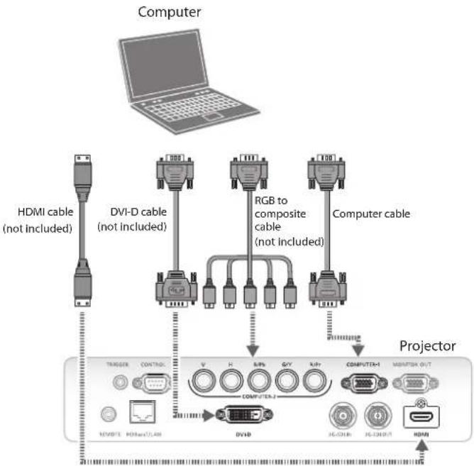
Connecting to the AV Equipment
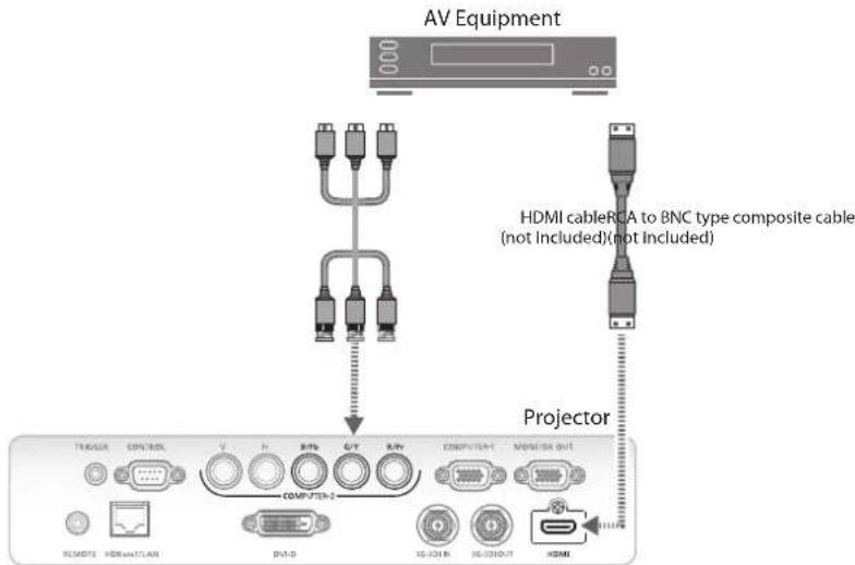
Connecting to the Control Devices
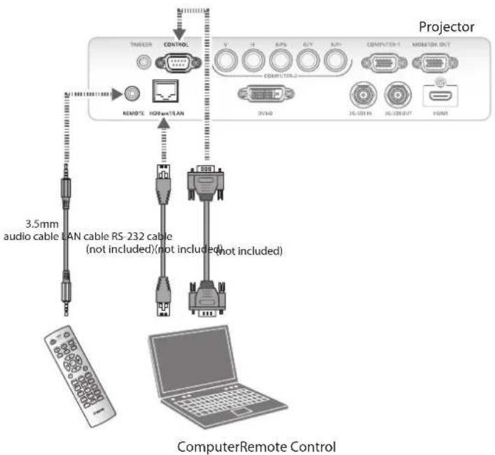
Connecting to the Screen Trigger
Connecting to the External HDBaseT Transmitter
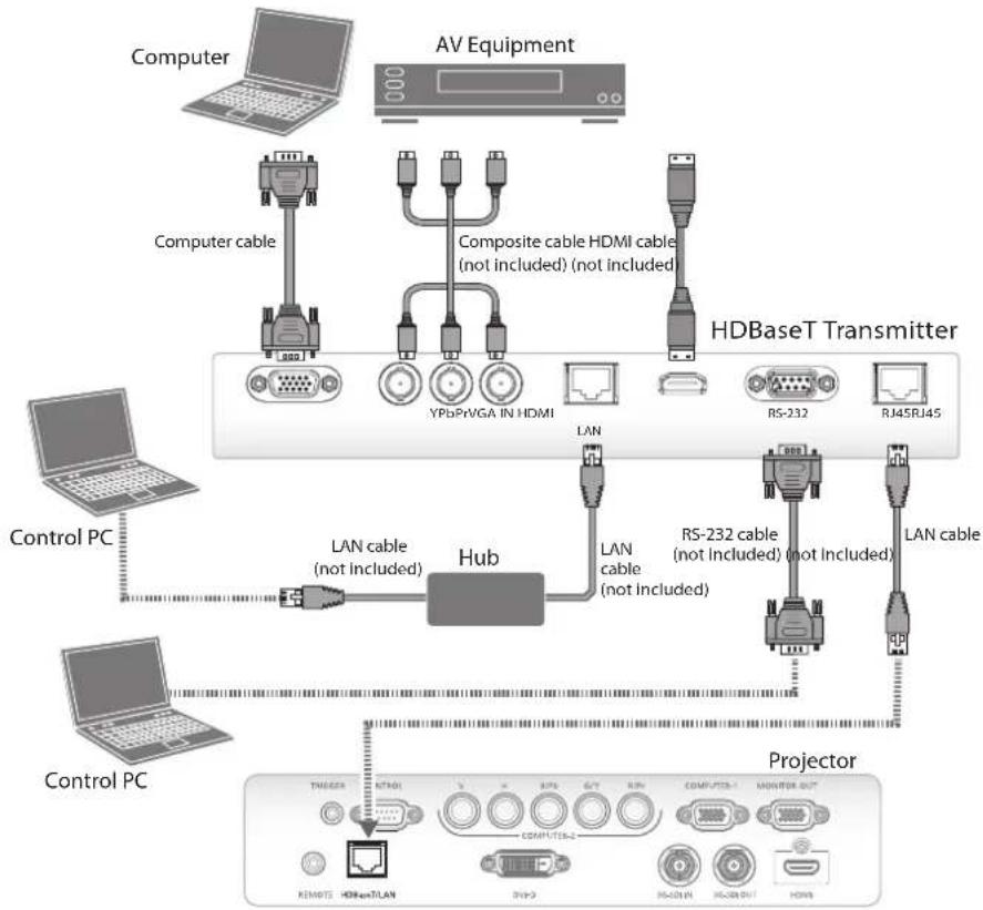
flowchart
graph TD
    A["Control PC"] -->|LAN cable (not included)| B["Hub"]
    C["Computer"] -->|Computer cable| D["AV Equipment"]
    D --> E["Composite cable HDMI cable (not included) (not included)"]
    E --> F["HDBaseT Transmitter"]
    F --> G["RS-232"]
    F --> H["RJ45RJ45"]
    I["Control PC"] --> J["LAN cable (not included)"]
    J --> K["Hub"]
    K --> L["LAN cable (not included)"]
    L --> M["RS-232 cable (not included) (not included)"]
    M --> N["LAN cable"]
    O["Projector"] --> P["TMEMS"]
    O --> Q["RETR"]
    O --> R["HDAT/LAN"]
    O --> S["COMPUTER"]
    O --> T["MONITOR OUT"]
    O --> U["REMOTE"]
    O --> V["HDMI"]
Connecting to the 3G-SDI
Connecting to the Extended Monitor
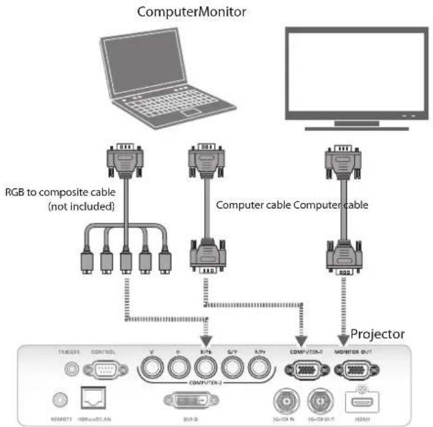
flowchart
graph TD
    A["ComputerMonitor"] --> B["RGB to composite cable (not included)"]
    A --> C["Computer cable Computer cable"]
    A --> D["Projector"]
    B --> E["TA/DCX1"]
    B --> F["CONTROL"]
    C --> G["COMPUTER-2"]
    C --> H["COMPVTR-2"]
    C --> I["MONITOR OUT"]
    D --> J["REMT3"]
    D --> K["HSPaveLAN"]
    D --> L["DVP-D"]
    D --> M["IG-DA R"]
    D --> N["IG-DA OUT"]
    D --> O["HDAM"]
Starting and Shutting down the Projector
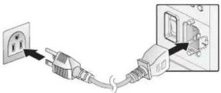
- Connect the power cord to the projector. Connect the other end to a wall outlet. ("Voltage Selection" on page 6 of AC input selected.)
- Fix the power cord to the power socket of the projector with a hook.
- Turn on the power switch.
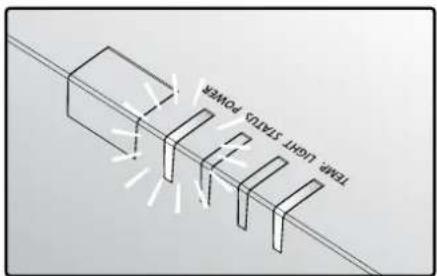
- Make sure the POWER LED displays solid red. Press the POWER button on the projector or the ON button on the remote control to turn on the projector. See "Power LED Indicator" on page 99.
natural_image
Electrical plug connection diagram showing power outlet and socket installation (no text or symbols)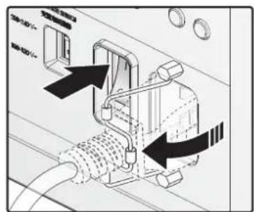
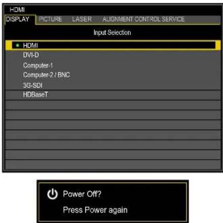
- Press the source buttons on the remote control or INPUT on the projector to select a desired input signal.
-
Press the POWER button on the projector or the OFF button on the remote control to show the "Power Off? / Press Power again" prompt.
-
Press the POWER button on the projector or the OFF button on the remote control to turn off the projector.
Note:
■ Use the projector's supplied power cord.
- Confirm the projector's power requirements before installing to make sure the power supply meets the projector's specification requirements.
■ Turn off this product when not in use to prolong the life of the projector. Laser life vary depending upon mode selected, environmental conditions, and usage. Brightness decreases over time.
Warning:
Do not unplug the power cord and do not turn off the power switch until the POWER LED solid red - indicating the projector has cooled down.
Adjusting the Projector Level
Take note of the following when setting up the projector:
■ The projector table or stand should be level and sturdy.
■ Position the projector so that it is perpendicular to the screen.
■ Ensure the cables are secured and out of the way to avoid tripping on them and prevent damage or injury.
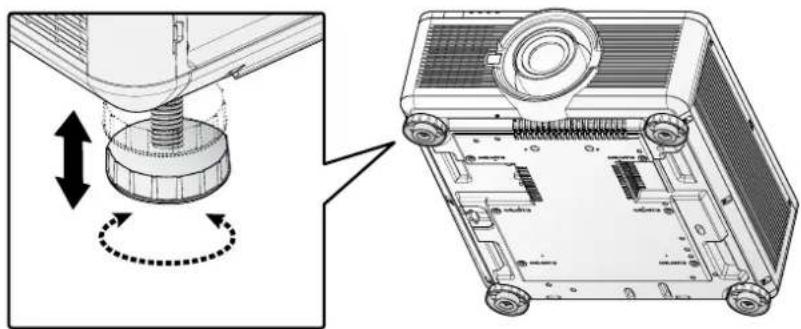
natural_image
Technical diagram showing a mechanical assembly with directional arrows and a 3D view of the internal components (no text or symbols present)To level the projector on the installation surface, turn the tilt-adjuster right or left until the desired angle is achieved.
Adjusting the Focus and Zoom
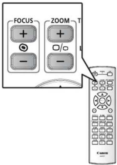
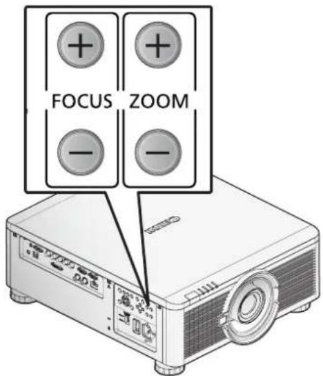
- Press FOCUS +/- on the projector or the remote control to sharpen the projected image.
- Press ZOOM +/- on the projector or the remote control to adjust the size of the image (ZOOM + increases image size, ZOOM - decreases image size).
Adjust the Keystone
- Press MENU. Press ◀ or ▶ to navigate to ALIGNMENT.
- Press ▲ or ▼ until Keystone is selected.
- Press ENTER to enter keystone control menu.
- Press ▲, ▼, ◀ or ▶ to correct keystone distortion.
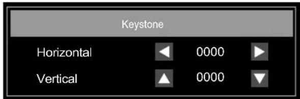
When the aspect is set to real in low-resolution mode, OSD may become out of range depending on the level of Keystone adjustment. See "Keystone" on page 58.
Adjusting the Lens Shift
The projector has the lens shift feature and the image can be vertically adjusted without moving the projector.
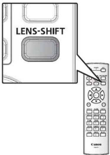
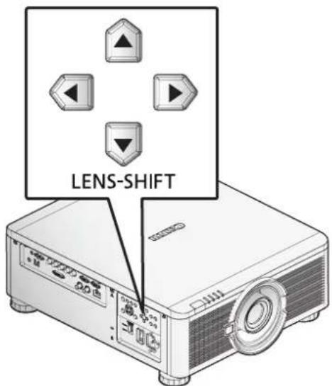
Vertical Lens Shift
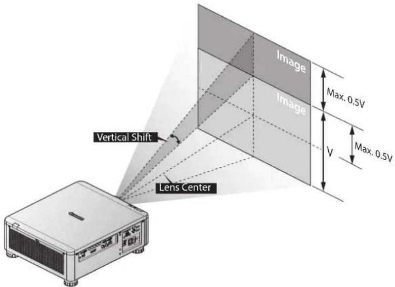
The lens on a desk mounted projector can move down to up from 0% to 50% (0.5V).
The lens of the ceiling mounted projector can move up to down from 0% to 50% (0.5V).
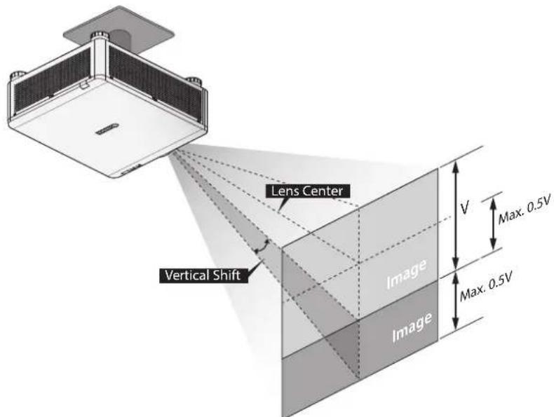
The above lens shift range is for LX-IL01UW (ultra wide zoom lens), LX-IL02WZ (wide zoom lens), LX-IL03ST (standard zoom lens), LX-IL04MZ (middle zoom lens), LX-IL05LZ (long zoom lens), LX-IL06UL (ultra long zoom lens), except LX-IL07WF (short fixed lens).
■ The LX-IL07WF (short fixed lens), optical performance guaranteed range is limited at 0% position.
Horizontal Lens Shift
The image can be shifted horizontally to the right or left by 10% (0.1H) without moving the projector.
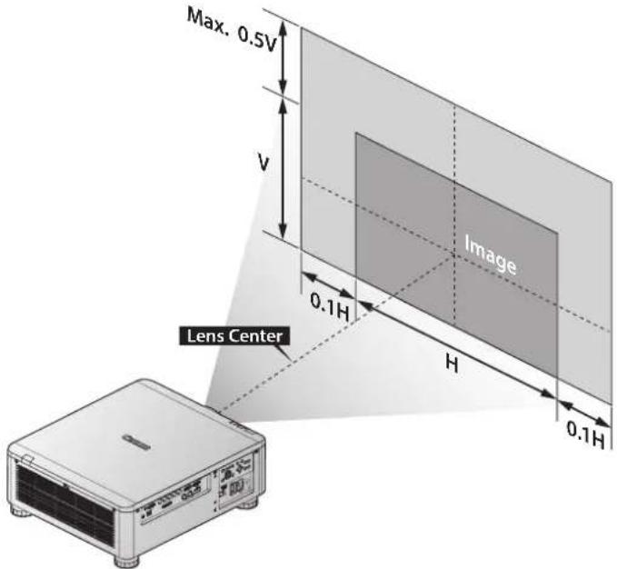
■ The above lens shift range is for LX-IL02WZ (wide zoom lens), LX-IL03ST (standard zoom lens), LX-IL04MZ (middle zoom lens), LX-IL05LZ (long zoom lens), LX-IL06UL (ultra long zoom lens).
■ The LX-IL07WF (short fixed lens), optical performance guaranteed range is limited at 0% position.
| Lens Shift Specification Vertical | Horizontal | |||
| Up Down | Left Right | |||
| Lens Shift Adjust Range 60% 30% 10% | 20% | |||
| Optical performance guaranteed range | 50% 0% | 10% 10% | ||
Horizontal Lens Shift for LX-IL01UW (Ultra Wide Zoom Lens)
The image can be shifted horizontally to the right or left by 6.70% (0.067H) without moving the projector.
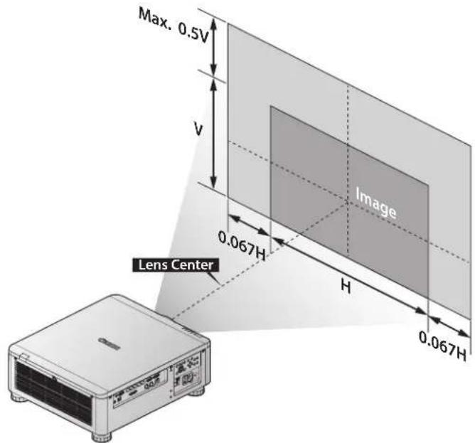
■ The above lens shift range is for LX-IL01UW (ultra wide zoom lens).
| Lens Shift Specification Vertical Horizontal | ||||
| Lens Shift Adjust Range 60% 30% 10% 20% | ||||
| Optical performance guaranteed range | 50% 0% 6.7% 6.7% | |||
On-Screen Display (OSD) Menu Settings
OSD Menu Controls
The projector has an OSD that lets you make image adjustments and change various settings.
Navigating the OSD
You can use ▲, ▼, ◀ or ▶ on the remote control or the projector keypad to navigate and adjust settings.
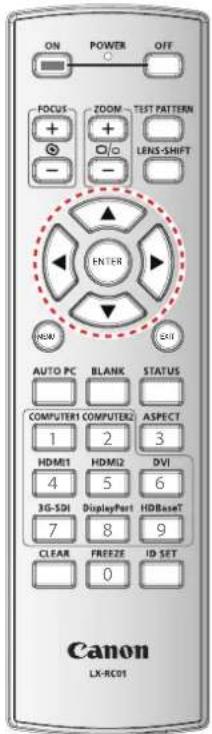
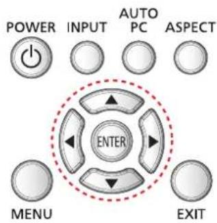
- Press MENU to enter the OSD.
- There are six menus. Press ◀ or ▶ to move through the menus.
- Press ▲ or ▼ to move up and down in a menu.
- Press ◀ or ▶ to change values for settings.
- Press MENU to close the OSD or return the previous menu.
Setting the OSD Language
Set the OSD language (default: English) to your preference before continuing.
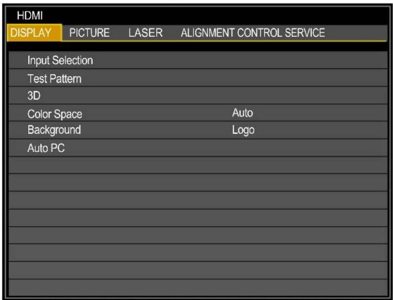
- Press MENU. Press ◀ or ▶ to navigate to CONTROL.
- Press ▲ or ▼ until Language is selected. Press ENTER to enter the Language menu.
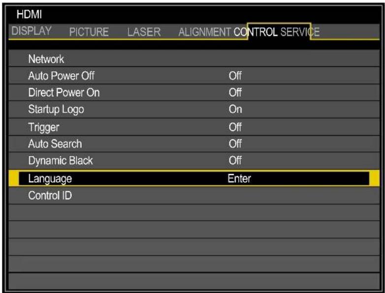
- Press ▲ or ▼ until the language you want is selected.
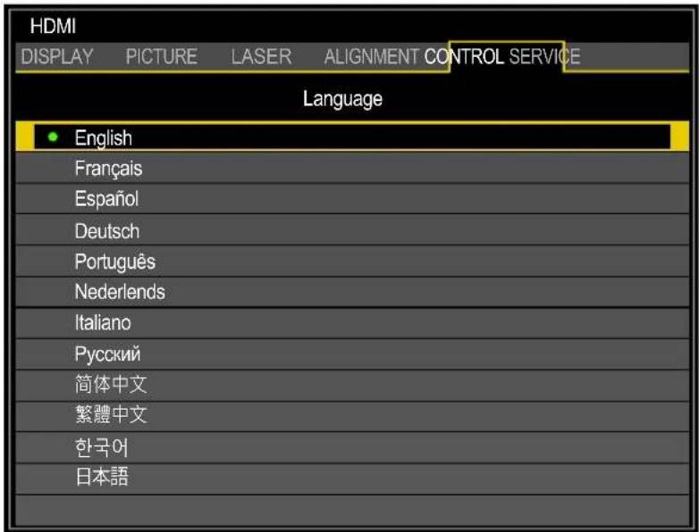
- Press MENU three times to close the OSD.
OSD Menu Overview
| Main Menu Sub Menu Setting | |||
| DISPLAY Input | Selection HDMI / DVI- | D / Computer-1 / Computer-2/BNC / 3G-SDI / HDBaseT | |
| Test Pattern White / Bl | Black / Red / Green / Blue / Checkerboard / CrossHatch / V Burst / H Burst / ColorBar | ||
| 3D 3D Format Off / Auto / Side by Side (Half) / Top and Bottom / Frame Sequential | |||
| Color Space Auto / REC709 / REC601 / RGB PC / RGB Video | |||
| Background Logo / Black / Blue / White | |||
| Auto PC Enter | |||
| PICTURE Picture | ure Mode Presentation / Standard / Video | ||
| Brightness 0 ~ 100 ~ 200 | |||
| Contrast 0 ~ 100 ~ 200 | |||
| Saturation | 0 ~ 100 ~ 200 | ||
| Hue | 0 ~ 100 ~ 200 | ||
| Gamma | 1.0 / 1.8 / 2.0 / 2.2 / 2.35 / 2.5 (Picture Mode: Presentation)1.0 / 1.8 / 2.0 / 2.2 / 2.35 / 2.5 (Picture Mode: Standard / Video) | ||
| Color | Hue | Red / Green / Blue / Cyan / Magenta / Yellow | |
| Saturation | Red / Green / Blue / Cyan / Magenta / Yellow | ||
| Gain | Red / Green / Blue / Cyan / Magenta / Yellow | ||
| White Gain | Red / Green / Blue | ||
| Color Temperature | 5400K / 6500K / 7500K / 8200K / 9300K / Native | ||
| White Balance | Red Offset / Green Offset / Blue Offset / Red Gain / Green Gain / Blue Gain | ||
| Sharpness | 0 ~ 15 | ||
| Noise Reduction | 0 ~ 3 | ||
| VGA Setup | V Start / H Start / H Phase / H Total | ||
| LASER | Power Mode | Eco / Normal / Custom | |
| Power Level LX-MU800Z: 20% ~ 100%LX-MU600Z: 35% ~ 100% | |||
| High Altitude | Auto / High | ||
Factory Settings are in bold letters.
| Main Menu S | Sub Menu Setting | ||
| ALIGNMENT | Projection Mode | Front Tabletop / Front Ceiling / Rear Tabletop / Rear Ceiling | |
| Lens Control Popup menu for Zoom, Focus and Shift control | |||
| Lens Memory Memory | 1 / Memory 2 / Memory 3 / Memory 4 / Memory 5 / Memory 6 / Memory 7 / Memory 8 | ||
| Center Lens Center Lens ? OK / Cancel | |||
| Geometry Aspect Ratio | 5:4 / 4:3 / 16:10 / 16 | 9 / 1.88 / 2.35 / Letterbox / Auto / True Size | |
| Overscan Off / Crop / Digital Alignment Digital Zoom / Digital Pan / Digital Scan / Reset | Zoom | ||
| Keystone Popup menu with X and Y adjustment, -600 < X < 600, -400 < Y < 400 | |||
| Rotation -100 ~ 100 | |||
| Pincushion / Barrel | Popup menu with X and Y adjustment, -150 < X < 300, -150 < Y < 300 | ||
| Top Left Corner | Popup menu with X and Y adjustment, -192 < X < 192, -120 < Y < 120 | ||
| Top Right Corner | Popup menu with X and Y adjustment, -192 < X < 192, -120 < Y < 120 | ||
| Bottom Left Corner | Popup menu with X and Y adjustment, -192 < X < 192, -120 < Y < 120 | ||
| Bottom Right Corner | Popup menu with X and Y adjustment, -192 < X < 192, -120 < Y < 120 | ||
| Reset | Enter | ||
| Blanking | Top / Bottom: 0 ~ 360Left / Right: 0 ~ 534 | ||
| Edge Blend | Edge Blend | Off / On | |
| Align Pattern | Off / On | ||
| Blend Width | Top / Bottom / Left / Right: 0, 100 ~ 800 | ||
| Black Level | Top / Bottom / Left / Right: 0 ~ 32All / Red / Green / Blue: 0 ~ 255 | ||
| Reset | Enter | ||
Factory Settings are in bold letters.
| Main Menu Sub Menu Setting | |||
| CONTROL Network Network Mode Pro | Projector Control / Service | ||
| Standby Power Off / On | |||
| DHCP Off / On | |||
| IP 192.168.0.100 (Enter to edit) | |||
| Subnet Mask 255.255.255.0 (Enter to edit) | |||
| Gateway 0.0.0.0 (Enter to edit) | |||
| DNS 0.0.0.0 (Enter to edit) | |||
| MAC 00:18:23:2c:eb:8a (example) | |||
| Auto Power Off Off / On | |||
| Direct Power On Off / On | |||
| Startup Logo Off / On | |||
| Trigger Off / On | |||
| Auto Search | Off / On | ||
| Dynamic Black | Off / On | ||
| Language | English / Français / Español / Deutsch / Português / Nederlands / Italiano / русский / 简体中文 / 繁體中文 / 한국어 / 日本語 | ||
| Control ID | Control ID Enable Off / On | ||
| Control ID Number 1 ~ 99 | |||
| Remote ID Number 1 ~ 99 (Need to press IR remote once) | |||
| SERVICE (for LX-MU800Z) | Model Name | LX-MU800Z | |
| Serial Number DDE30 | 0001A (example) | ||
| Software Version 1 | MM01-SD07-FD19 (example) | ||
| Software Version 2 | LD06-22-RP02-3092 (example) | ||
| Control / Remote ID | X / X | ||
| Active Source | HDMI (example) | ||
| Signal Format | 1920x1200 60Hz RB (example) | ||
| Pixel Clock | 154.00 MHz (example) | ||
| H/V Refresh Rate | 74.038 KHz / 59.95 Hz (example) | ||
| Laser Hours | 000100 HRS (example) | ||
| Thermal Status | Inlet Temperature | 25 / 25 (°C) | |
| DMD Temperature | 32 (°C) | ||
| Laser Temperature | 33 / 30 (°C) | ||
| Water Pump RPM | 3900 | ||
| Fan 1-3 Speed | 1400 / 1400 / 1400 | ||
| Fan 4-6 Speed | 1400 / 1200 / 1200 | ||
| Fan 7-9 Speed | 1200 / 1400 / 1400 | ||
| Fan 10-12 Speed 0 / 3000 / 3000 | |||
| Fan 13-15 Speed 3000 / 3000 / 3000 | |||
| Fan 16 Speed | 3000 | ||
| Factory Reset | Reset Everything ? | OK / Cancel | |
Factory Settings are in bold letters.
| Main Menu Sub Menu Setting | ||
| SERVICE (for LX-MU600Z) | Model Name LX-MU600Z | |
| Serial Number DEE30 | 0001A (example) | |
| Software Version 1 MM01-SD07-FD19 (example) | ||
| Software Version 2 LD06-22-RP02-3092 (example) | ||
| Control / Remote ID X / X | ||
| Active Source HDMI (example) | ||
| Signal Format 1920x1 | 200 60Hz RB (example) | |
| Pixel Clock 154.00 MHz (example) | ||
| H/V Refresh Rate 74.038 KHz / 59.95 Hz (example) | ||
| Laser Hours 000100 HRS (example) | ||
| Thermal Status Inlet T | Temperature 25 / 25 (°C) | |
| DMD Temperature 32 (°C) | ||
| Laser Temperature 33 / 30 (°C) | ||
| Water Pump RPM 3900 | ||
| Fan 1-3 Speed 1400 / 1400 / 1400 | ||
| Fan 4-6 Speed 1400 / 1200 / 1200 | ||
| Fan 7-9 Speed 1200 / 1400 / 1400 | ||
| Fan 10-12 Speed 0 / 3000 / 3000 | ||
| Fan 13-15 Speed 3000 / 3000 / 3000 | ||
| Fan 16 Speed 3000 | ||
| Factory Reset Reset Everything ? OK / Cancel | ||
Factory Settings are in bold letters.
DISPLAY Menu
| HDMI | |||
| DISPLAY | PICTURE | LASER | ALIGNMENT CONTROL SERVICE |
| Input Selection | |||
| Test Pattern | |||
| 3D | |||
| Color Space | Auto | ||
| Background | Logo | ||
| Auto PC | |||
| Label Description | |
| Input Selection Press ENTER to enter the Input Selection menu. | |
| Test Pattern Press ENTER to display different test patterns for projector installation check. Press EXIT or TEST PATTERN to close test pattern. | |
| 3D | Press ENTER to enter the 3D menu. See “3D Menu” on page 49.Note:Before adjusting the 3D setting, ensure the input signal is connected. |
| Color Space | Press ◀ or ▶ to adjust the color space. The options are Auto, REC709, REC601, RGB PC or RGB-Video. |
| Background Press ◀ or | ▶ to specify the image to be background when no signal. The options are Logo, Blue, Black or White. |
| Auto PC Press ENTER to execute the auto sync input signal. | |
3D Menu
| Label Description | |
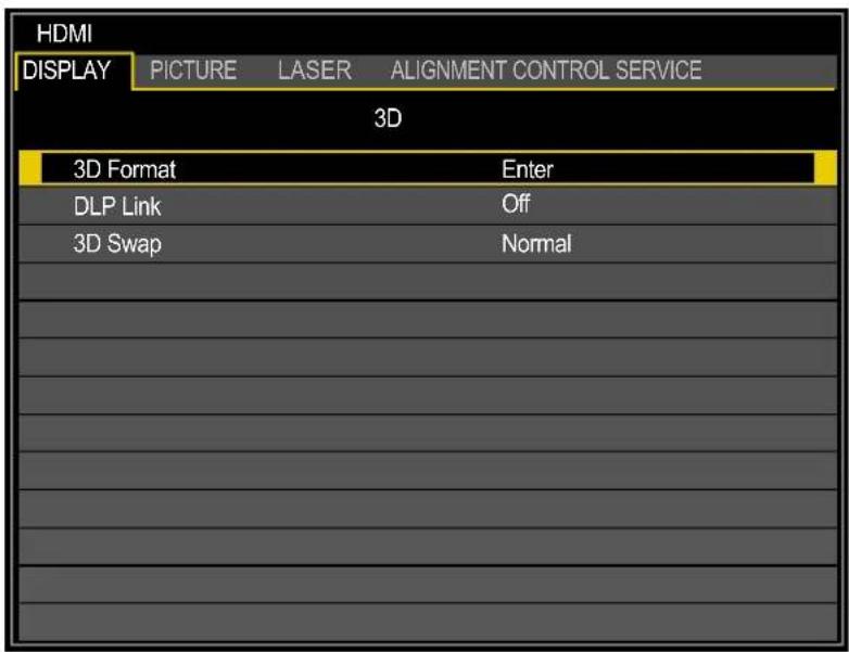
| 3D Format* | Press ENTER to open the 3D Format window. Press ▲ or ▼ to select the 3D format. The options are Off, Auto, Side by Side (Half), Top and Bottom or Frame Sequential.Side by Side (Half): Transmission of separate images for left and right sides, placed next to each other. The image's horizontal definition is halved.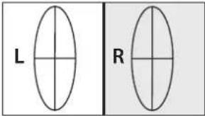 Top and Bottom: Transmission of separate images for left and right sides, placed one above the other. The image's vertical definition is halved. Top and Bottom: Transmission of separate images for left and right sides, placed one above the other. The image's vertical definition is halved.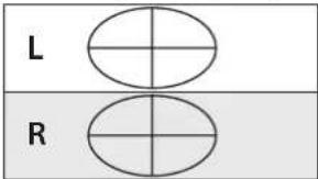 Frame Sequential: Transmission of separate images for left and right sides in sequence producing a single video stream.Top and Bottom Frame Sequential: Transmission of separate images for left and right sides in sequence producing a single video stream.Top and Bottom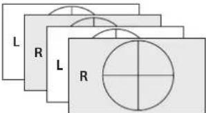 Frame Sequential Frame Sequential |
| DLP Link Press ◀ or ▶ | to activate or deactivate the DLP Link sync. |
| 3D Swap Press ◀ or ▶ | to select a status for 3D images viewed through the 3D glasses. The options are Normal or Reverse. |

■ The freeze function cannot be used during 3D projection.
■ Please select AUTO once again or select a known 3D format, when a 3D signal is not detected normally even if a 3D format is set by AUTO.
PICTURE Menu
| HDMI | |||
| DISPLAY | PICTURE | LASER | ALIGNMENT CONTROL SERVICE |
| Picture Mode | Presentation | ||
| Brightness | 100 | ||
| Contrast | 100 | ||
| Saturation | 100 | ||
| Hue | 100 | ||
| Gamma | 2.2 | ||
| Color | |||
| Color Temperature | Native | ||
| White Balance | |||
| Sharpness | 10 | ||
| Noise Reduction | 0 | ||
| VGA Setup | |||
| Label Description | |
| Picture Mode (*1) | Press ◀ or ▶ to select a picture mode. The options are Presentation, Standard and Video.Presentation: Suitable for viewing text-based images in a bright room.Standard: Suitable for projecting a computer screen or watching media played with video software in a bright room. This image mode emphasizes white tones.Video: Suitable for watching video taken with a video camera in a moderately dark room. |
| Brightness (*2) Press ◀ | or ▶ to adjust the brightness of the projected image. |
| Contrast Press ◀ or ▶ | to adjust the contrast of the projected image. |
| Saturation (*3) Press ◀ | or ▶ to adjust the saturation level of the color. |
| Hue (*3) Press ◀ or ▶ | to adjust the level of hue for reproduction of the true color. |
| Gamma Press ◀ or ▶ | to adjust the gamma correction of the projected image. The options are 1.0, 1.8, 2.0, 2.2, 2.35 and 2.5. |
| Color | Press ENTER to enter the Color menu. See “Color Menu” on page 51. |
| Color Temperature (*1) | Press ◀ or ▶ to adjust the color temperature. The options are Native, 5400K, 6500K, 7500K, 8200K and 9300K. |
| White Balance | Press ENTER to enter the White Balance menu. Press ▲, ▼, ◀ or ▶ to adjust settings. |
| Sharpness Press ◀ or ▶ | to adjust the sharpness. |
| Noise Reduction Press ◀ or ▶ to adjust the noise of the projected image. | |
| VGA Setup (*1) (*4) | Press ENTER to enter the VGA Setup menu. See “VGA Setup Menu” on page 52. |
(*1) This function is grayed-out and unusable when in 3D projection.
(*2) The Brightness setting does not affect maximum brightness. To change the laser brightness mode, use the Power Mode setting.
(*3) Adjustment is possible only when video signal is input.
(*4) Adjustment is possible only when signals from the computer is input through Computer-1 and Computer-2/BNC.
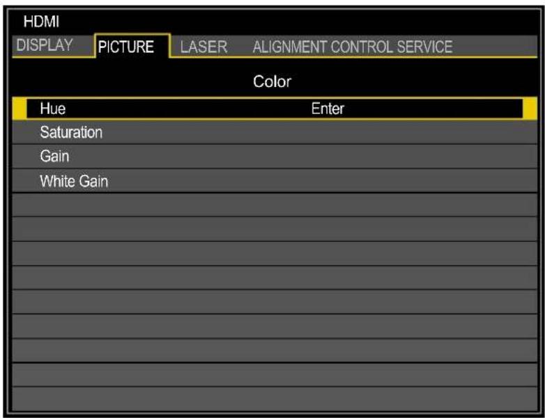
Color Menu
| Label Description | |
| Hue | Press ENTER to enter the Hue menu. Press ▲, ▼, ◀ or ▶ to adjust settings. |
| Saturation | Press ENTER to enter the Saturation menu. Press ▲, ▼, ◀ or ▶ to adjust settings. |
| Gain | Press ENTER to enter the Gain menu. Press ▲, ▼, ◀ or ▶ to adjust settings. |
| White Gain | Press ENTER to enter the White Gain menu. Press ▲, ▼, ◀ or ▶ to adjust settings. |
VGA Setup Menu
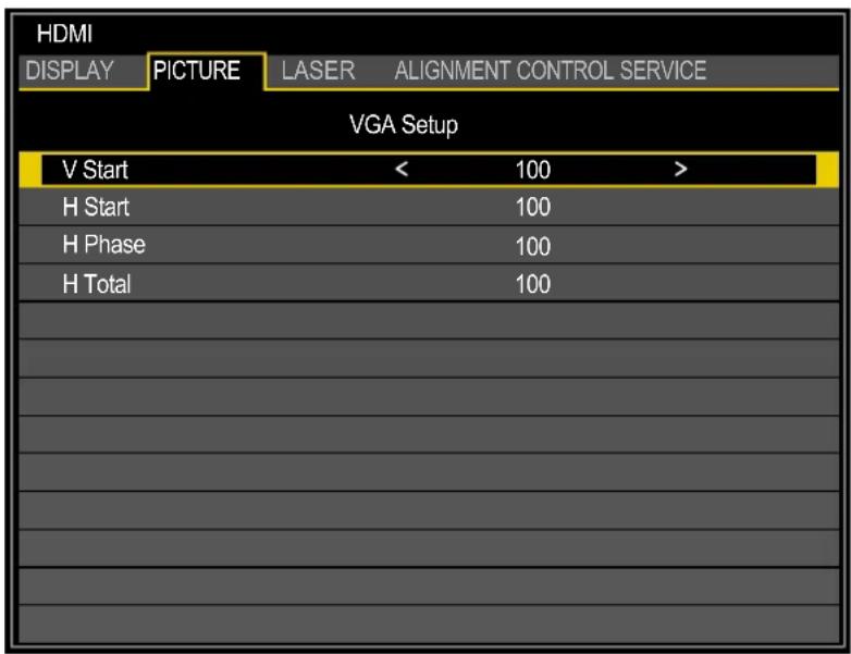
| Label Description | |
| V Start Press ◀ or ▶ to | adjust V Start for the Computer-1 / Computer-2/BNC signal display. |
| H Start Press ◀ or ▶ to | adjust H Start for the Computer-1 / Computer-2/BNC signal display. |
| H Phase Press ◀ or ▶ to | to adjust H Phase for the Computer-1 / Computer-2/BNC signal display. |
| H Total Press ◀ or ▶ to | adjust H Total for the Computer-1 / Computer-2/BNC signal display. |
LASER Menu
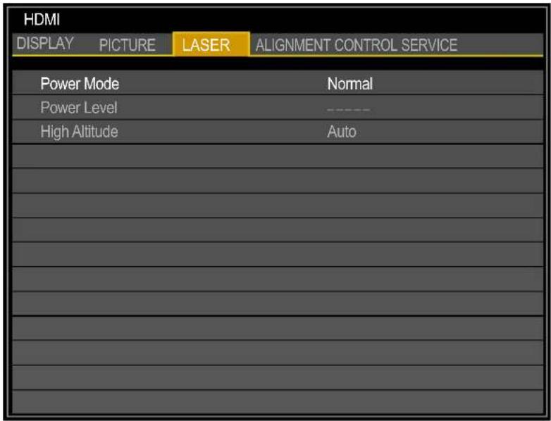
| Label Description | |
| Power Mode | Press◀ or ▶ to select a power mode. The options are Normal, Eco or Custom. |
| Power Level Press◀ or | ▶ to adjust custom power level. The function is only available when Power Mode is Custom. Adjust the power level may change the brightness. |
| High Altitude | There are two High Altitude mode settings: Auto and High.Auto:The rotation rate of the fan is adjusted automatically to match the ambient temperature and air pressure.High:The rotation rate of the fan is set to maximum.Press◀ or ▶ to select a high altitude setting Auto or High.The high-altitude mode must be set to High under the following conditions:■ The elevation is 1,219 meters (4,000 feet) or above.■ The tilt angle of the projector is greater than ±10 degrees.Note:If the projector is in operation in a high heat or high altitude environment, it may shut down automatically. In this setup, you can enable the High Altitude function by selecting High and setting the fan to operate at a higher speed to maintain proper cooling levels on the projector. |
ALIGNMENT Menu
| HDMI | |||
| DISPLAY | PICTURE | LASER | ALIGNMENT CONTROL SERVICE |
| Projection Mode | Front Table | ||
| Lens Control | |||
| Lens Memory | |||
| Center Lens | |||
| Geometry | |||
| Edge Blend | |||
| Label Description | |
| Projection Mode | Press ◀ or ▶ to select a projection mode. The options are Front Tabletop, Front Ceiling, Rear Tabletop and Rear Ceiling. |
| Lens Control | Press ENTER to enter the Lens Control menu. See “Lens Control Menu” on page 55. |
| Lens Memory | Press ENTER to enter the Lens Memory menu. See “Lens Memory Menu” on page 56. |
Center Lens Press ENTER to set the lens to the default center position.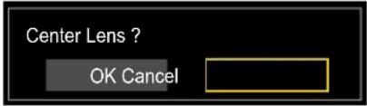 Note:Calibrate the lens whenever a lens is mounted on the projector. Note:Calibrate the lens whenever a lens is mounted on the projector. | |
| Geometry | Press ENTER to enter the Geometry menu. See “Geometry Menu” on page 57. |
| Edge Blend | Press ENTER to enter the Edge Blend menu. See “Edge Blend Menu” on page 62. |
Lens Control Menu
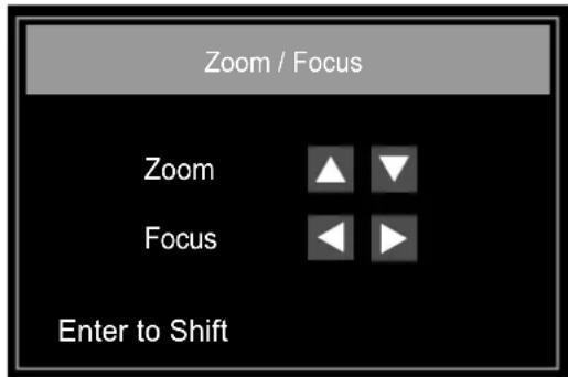
Switch between Lens Shift, Zoom/Focus menus by pressing ENTER button.
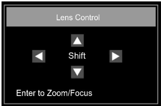
| Label Description | |
| Zoom Press ▲ or ▼ to adjust zooming of the lens. | |
| Focus Press ◀ or ▶ to adjust focusing of the lens. | |
| Lens Shift V Press ▲ or ▼ to adjust horizontal shift of the lens. | |
| Lens Shift H Press ◀ or ▶ to adjust vertical shift of the lens. |
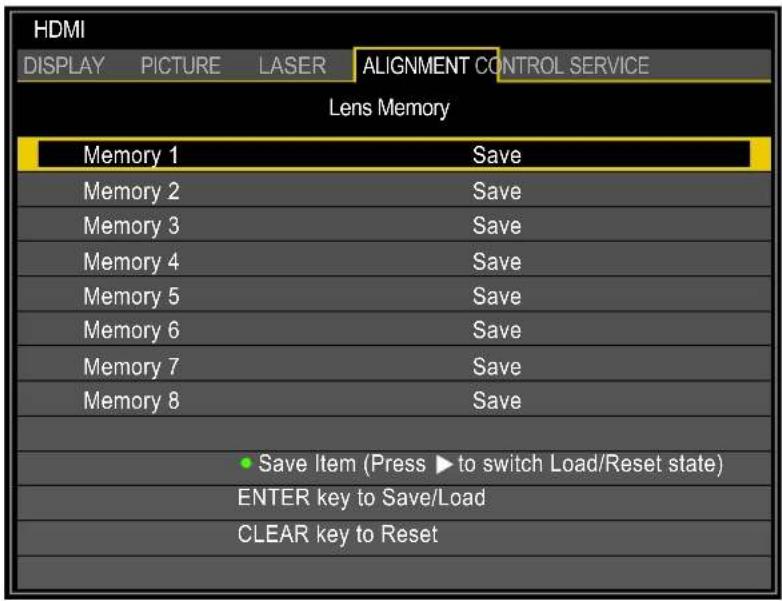
Lens Memory Menu
The projector can save information about the lens position in memory. Up to eight sets of lens information (including focus, zoom, and lens shift settings) can be saved, and the lens can be restored to these positions.
| Label Description | |
| Memory 1 ~ 8 | Press ▲ or ▼ to select, press ENTER to save settings and open the keyboard. Press ▲, ▼, ◀ or ▶ and ENTER to select or confirm the setting.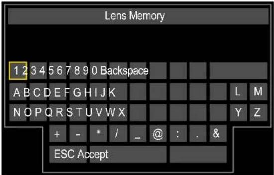 Press ▶ to switch to Reset and press CLEAR to reset the memory name.Note:A maximum number of nine letters, numbers, symbols and spaces are allowed. Press ▶ to switch to Reset and press CLEAR to reset the memory name.Note:A maximum number of nine letters, numbers, symbols and spaces are allowed. |
Note:
■ When saved lens positions are restored, images may be projected in a slightly different position than the saved position.
■ When precise positioning is needed, use lens shift, zoom, and focus functions for fine adjustment.
Geometry Menu
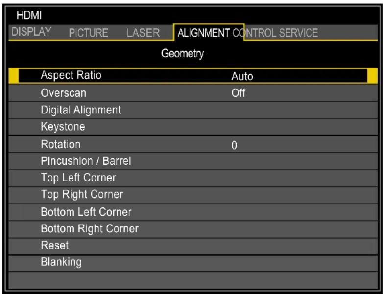
| Label Description | |
| Aspect Ratio Press ◀ or | ► to adjust the aspect of the projected image.5:4: The image is projected using an input signal aspect ratio of 5:4. Select 5:4 if an image of 5:4 aspect ratio cannot be correctly projected inAuto mode.4:3: The image is projected using an input signal aspect ratio of 4:3. Select 4:3 if an image of 4:3 aspect ratio cannot be correctly projected inAuto mode.16:10: The image is projected using an input signal aspect ratio of 16:10. Select 16:10 if an image of 16:10 aspect ratio cannot be correctly projected inAuto mode.16:9: The image is projected using an input signal aspect ratio of 16:9. Select 16:9 if an image of 16:9 aspect ratio cannot be correctly projected inAuto mode.1.88: The image is projected using an input signal aspect ratio of 1.88:1. Select 1.88:1 if an image of 1.88:1 aspect ratio cannot be correctly projected inAuto mode.2.35: The image is projected using an input signal aspect ratio of 2.35:1. Select 2.35:1 if an image of 2.35:1 aspect ratio cannot be correctly projected inAuto mode.Letterbox: The image of a letterbox signal is stretched equally in the horizontal and vertical directions to fit the screen. Parts of the displayed image are cropped at the top and bottom edges and therefore not visible.Auto: An image is projected at the aspect ratio of the input signal. Select this mode for normal image projection.True Size: The image is projected with the original resolution of the input signal. Select this to clearly project a computer screen image that has a resolution of WUXGA or lower. |
| Overscan (*1) (*2) Press | ◄ or ► to hide edge of the projected image to damage the noise appear. The options areOff,CropandZoom. |
| Digital Alignment (*1) | Press ENTER to enter the Digital Alignment menu. See “Digital Alignment Menu” on page 61. |
(*1) This function is grayed-out and unusable when in 3D projection. Additionally, settings made in 2D projection will be reset (turned to 0) when 3D projection is turned on.
(*2) If there's black band or noise surrounding the image of analog input, set Overscan to Crop.
| Label Descripti on | ||
Keystone Press ▲, ▼,◀ or ► to adjust horizontal or vertical distortion brought by the projection angle. Keystone Example 1. The projector is positioned at an angle. 2. The resulting image is distorted. 3. The image is corrected. 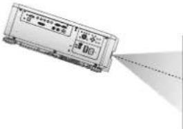   Keystone Settings 1. To correct the right side of the image The projector is positioned to the left of the screen. To correct, apply a positive Horizontal Keystone value pressing ►. 2. To correct the top of the image The projector is positioned below the screen at an upward angle. To correct, apply a positive Vertical Keystone value pressing ▲. 3. To correct the bottom of the image The projector is positioned above the screen at a downward angle. To correct, apply a negative Vertical Keystone value pressing ▼. 4. Projector straight The projector is directly opposite the screen at a right angle both horizontally and vertically. No correction is needed. 5. To correct the left side of the image The projector is positioned to the right of the screen. To correct, apply a negative Horizontal Keystone value pressing ◀. Keystone Settings 1. To correct the right side of the image The projector is positioned to the left of the screen. To correct, apply a positive Horizontal Keystone value pressing ►. 2. To correct the top of the image The projector is positioned below the screen at an upward angle. To correct, apply a positive Vertical Keystone value pressing ▲. 3. To correct the bottom of the image The projector is positioned above the screen at a downward angle. To correct, apply a negative Vertical Keystone value pressing ▼. 4. Projector straight The projector is directly opposite the screen at a right angle both horizontally and vertically. No correction is needed. 5. To correct the left side of the image The projector is positioned to the right of the screen. To correct, apply a negative Horizontal Keystone value pressing ◀. 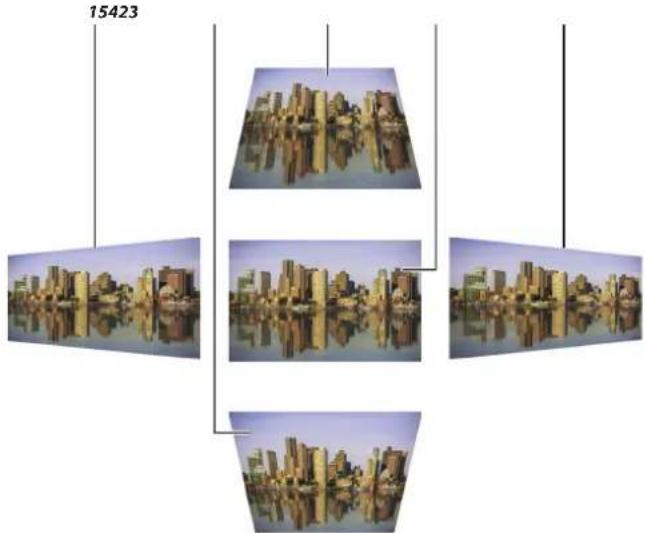 Horizontal and vertical keystone corrections Horizontal and vertical keystone corrections |
Note:
Following functions cannot be used at the same time:
Digital Alignment, Keystone, Rotation, Pincushion / Barrel and Corner adjustment
When a different function is selected, the previously set function is canceled.
| Label Description | |
| Rotation Press ◀ or ▶ to rotate the image until it is good position. | |
| Pincushion / Barrel | Press ENTER to enter the Pincushion / Barrel menu. Press ▲, ▼, ◀ or ▶ to correct the pincushion distortion.Top / Bottom Example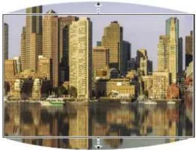 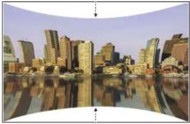 Left / Right Example Left / Right Example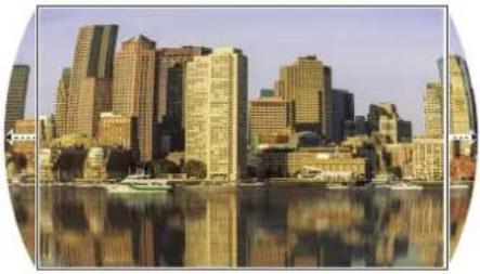 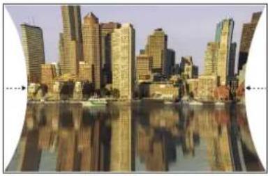 |
Top Left Corner Apply horizontal / vertical correction as necessary to restore the rectangular shape of the image.Press ENTER to enter the Top Left Corner menu. Press ▲, ▼, ◀ or ▶ to correct the distortion.Top Left Corner Example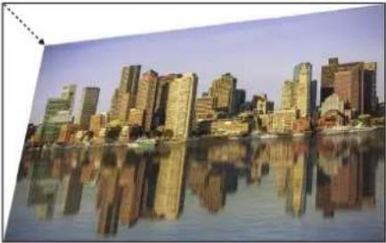 Top Left Corner correction Top Left Corner correction | |
| Top Right Corner Apply horizontal / vertical correction as necessary to restore the rectangular shape of the image.Press ENTER to enter the Top Right Corner menu. Press ▲, ▼, ◀ or ▶ to correct the distortion. | |
| Bottom Left Corner Apply horizontal / vertical correction as necessary to restore the rectangular shape of the image.Press ENTER to enter the Bottom Left Corner menu. Press ▲, ▼, ◀ or ▶ to correct the distortion. | |
| Note:Following functions cannot be used at the same time:Digital Alignment, Keystone, Rotation, Pincushion / Barrel and Corner adjustmentWhen a different function is selected, the previously set function is canceled. | |
| Bottom Right Corner Apply horizontal / vertical correction as necessary to restore the rectangular shape of the image.Press ENTER to enter the Bottom Right Corner menu. Press ▲, ▼, ◀ or ► to correct the distortion. | |
| Reset Press ENTER to set to the default value. | |
| Blanking | Press ENTER to enter the Blanking menu. Press ▲, ▼, ◀ or ► to adjust the display area. Press ▲ or ▼ to select Reset and press ENTER to set the settings to the default values. |
Note:
Following functions cannot be used at the same time:
Digital Alignment, Keystone, Rotation, Pincushion / Barrel and Corner adjustment
When a different function is selected, the previously set function is canceled.
Digital Alignment Menu
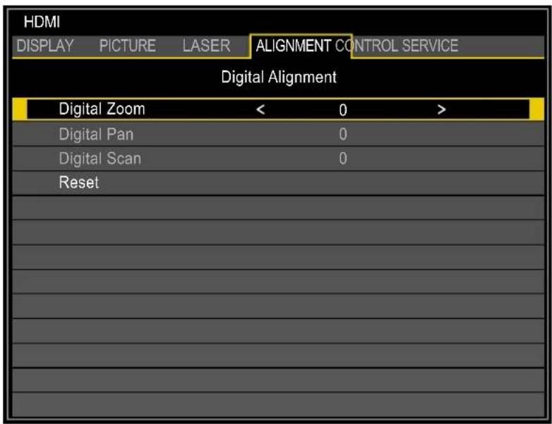
| Label Description | |
| Digital Zoom Press ◀ or | ▶ to enlarge the projected image.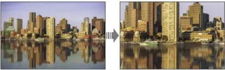 |
| Digital Pan Press ◀ or | ▶ to move the projected image horizontally. The function is only available when the image is enlarged.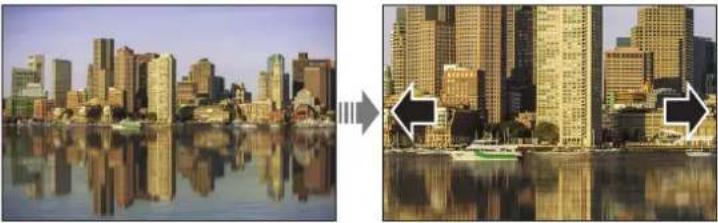 |
| Digital Scan Press ◀ or | ▶ to move the projected image vertically. The function is only available when the image is enlarged.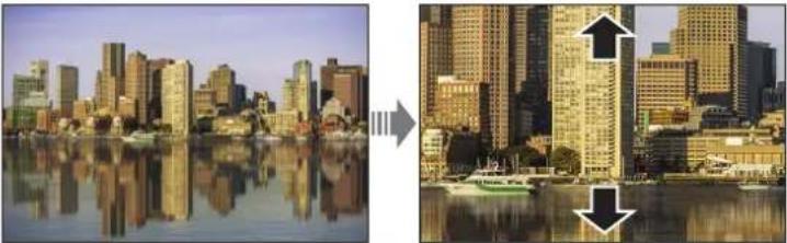 |
| Reset Press ENTER to set to the default value. | |
Edge Blend Menu
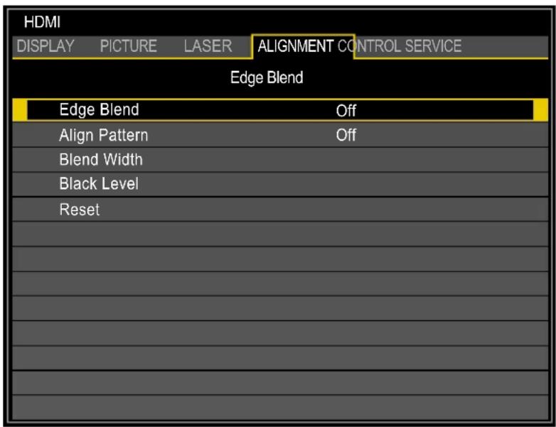
| Label Description | |
| Edge Blend By combining multiple projectors, a high resolution video can be projected on an even bigger screen using the Edge Blend function. Press ◀ or ▶ to enable or disable the edge blend function. Placing two projectors side by side | |
| Projected area Projected area Projector A P rojector B | |
| Align Pattern Make the overlaps more visible and help adjusting the physical position of the projectors in the array.Press ◀ or ▶ to enable or disable the align pattern function. | |
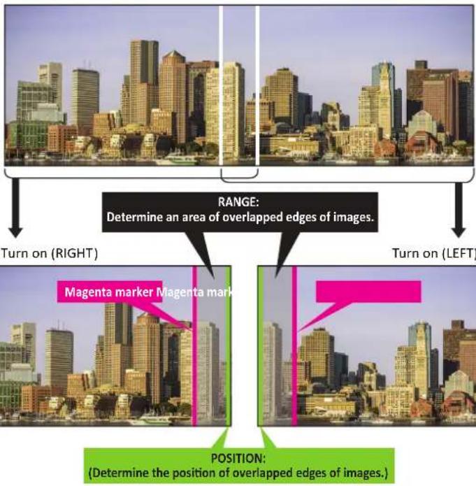 | |
| Blend Width | Press ENTER to enter the Blend Width menu. Press ▲, ▼, ◀ or ▶ to adjust settings.Top / Bottom Example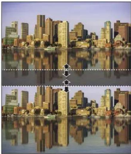 Left / Right Example Left / Right Example |
| Black Level | Press ENTER to enter the Black Level menu. Press ▲, ▼, ◀ or ▶ to adjust settings.Adjusting the Black Level when placing two projectors side by side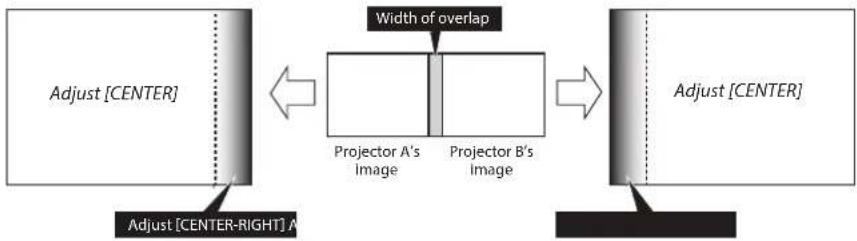 Adjusting the Black Level when placing four projectors side by side (Blend Along Corners) Adjusting the Black Level when placing four projectors side by side (Blend Along Corners)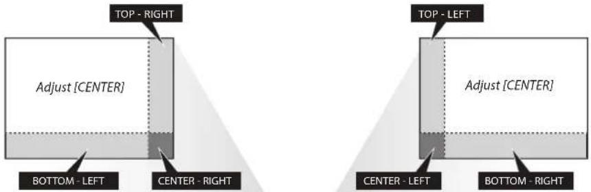 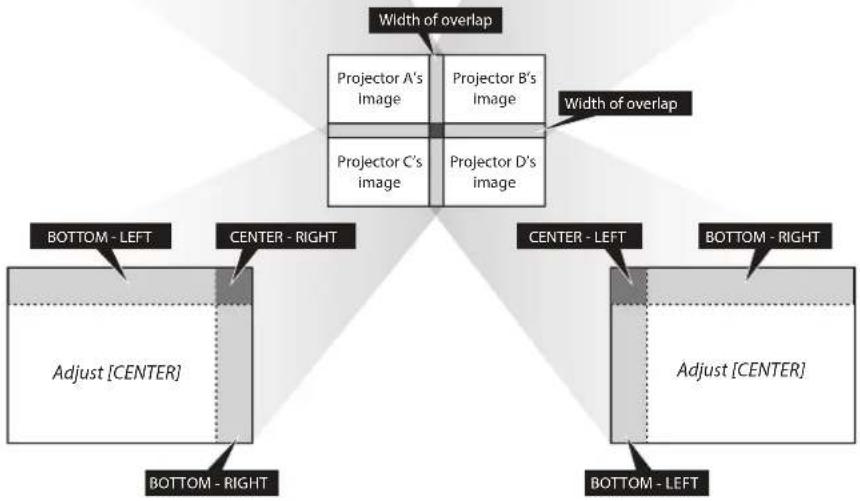 |
| Reset Press ENTER to set to the default value. | |
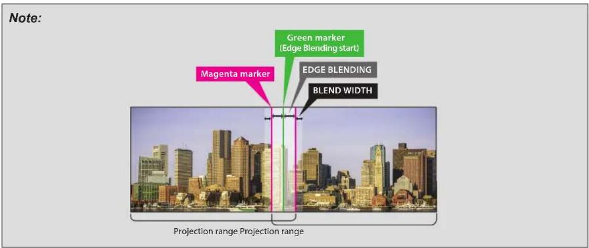
Possible Geometry and Edge Blend Combinations
Some Geometry and Edge Blend settings cannot be used in combination with others. The table below shows the possible combinations:
| Warping Blending | |||||||||
| Keystone | Rotation | Pincushion / Barrel | 4-Corners | Blanking | White Level | Black Level | |||
| Top/Bottom or Left/Right Only | Adjust | ||||||||
| Warping | Keystone - XXXOO | O | |||||||
| Rotation X - XXOO | O | ||||||||
| Pincushion / Barrel XX - X | OOO | ||||||||
| 4-Corners XXX - OO | O | ||||||||
| Blanking O O O O - O | O | ||||||||
| Blending | White Level | Top/Bottom or Left/Right Only | OO | OOO | - | O | |||
| Black Level | Adjust | O | O | O | O | O | O | - | |
O: Possible
X: Not possible
CONTROL Menu
| HDMI | |||
| DISPLAY | PICTURE | LASER | ALIGNMENT CONTROL SERVICE |
| Network | |||
| Auto Power Off | Off | ||
| Direct Power On | Off | ||
| Startup Logo | On | ||
| Trigger | Off | ||
| Auto Search | Off | ||
| Dynamic Black | Off | ||
| Language | |||
| Control ID | |||
| Label Description | |
| Network | Press ENTER to enter the Network menu. See “Network Menu” on page 67. |
| Auto Power Off Press ◀ | or ▶ to enable or disable turning off the projector when no input signal is received within 15 minutes. |
| Direct Power On Press ◀ | or ▶ to enable or disable turning on the projector when connect to an AC power. |
| Startup Logo Press ◀ or | ▶ to enable or disable the Startup Logo. |
| Trigger Press ◀ or ▶ to | enable or disable turning on the screen when the projector is powered on. |
| Auto Search Press ◀ or | ▶ to enable or disable auto search function. |
| Dynamic Black* Press ◀ | or ▶ to enable or disable dynamic black function |
| Language | Press ENTER to enter the Language menu. Press ▲ or ▼ to select the language of OSD menu. The options are English, Français, Español, Deutsch, Português, Nederlands, Italiano, русский, 简体中文, 繁體中文, 한국어 and 日本語 . |
| Control ID | Press ENTER to enter the Control ID menu. See “Control ID Menu” on page 76. |
* Optimizes the contrast depending on the brightness of each scene by adjusting laser output automatically based on the brightness data from the input signal.
Note:
The laser output turns off when the brightness of the input signal drops to a certain level.
Network Menu

| Label Description | |
| Network Mode | Press ◀ or ▶ to select the network control. The options are Projector Control and Service. |
| Standby Power (*1) Press | ◀ or ▶ to enable or disable the standby power function. |
| DHCP (*2) Press ◀ or ▶ | to enable or disable DHCP setting. |
| IP | Press ENTER to adjust the setting. Press ◀ or ▶ to select the number in the address and press ▲ or ▼ to increase or decrease the selected number.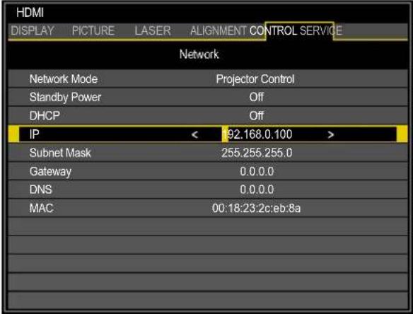 |
| Subnet mask Use it to set the subnet mask. The input method is same as the IP address. | |
| Gateway Use it to set the gateway. The input method is same as the IP address. | |
| DNS Use it to set the DNS. The input method is same as the IP address. | |
| MAC Displays the current MAC address. | |
(*1) During standby, this must be set to On when controlling the projector via LAN or HDBaseT. Also, the only control command that can be received during standby is Power On.
(*2) The function is only available when Network Mode is Projector Control.
For simplicity and ease of operation, the projector provides diverse networking and remote management features.
The LAN/RJ45 function of the projector through a network, such as remotely manage: Power On/Off, Brightness and Contrast settings. Also, projector status information, such as: Video-Source, etc.
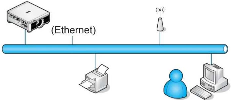
flowchart
graph LR
    A["Printer"] -->|Ethernet| B["Printer"]
    B --> C["User"]
    C --> D["Computer"]
    D --> E["Wireless Signal"]
    style A fill:#f9f,stroke:#333
    style B fill:#ccf,stroke:#333
    style C fill:#cfc,stroke:#333
    style D fill:#fcc,stroke:#333
    style E fill:#cff,stroke:#333
The projector can be controlled by a PC (Laptop) or other external device with connecting to the projector's LAN/RJ45 port.
Wired LAN Terminal Functionalies
Remote control and monitoring of a projector from a PC (or Laptop) via wired LAN is also possible. Compatibility with Crestron / AMX (Device Discovery) / Extron control boxes enables not only collective projector management on a network but also management from a control panel on a PC (or Laptop) browser screen.
■ Crestron is a registered trademark of Crestron Electronics, Inc. of the United States.
■ Extron is a registered trademark of Extron Electronics, Inc. of the United States.
■ AMX is a registered trademark of AMX LLC of the United States.
Note:
There is a limitation of power on/off control sequence in Network mode. It must take around 8\~9 sec after executing the power on command, regardless over the keypad, remote or IP.
Supported External Devices
This projector is supported by the specified commands of the Crestron Electronics controller and related software (ex, RoomView ^® ).
http://www.crestron.com/
This projector is supported by AMX (Device Discovery).
http://www.amx.com/
This projector is compliant to support Extron device(s) for reference.
http://www.extron.com/
LAN RJ45
- Connect an LAN cable to the RJ45 port on the projector and the PC (Laptop).
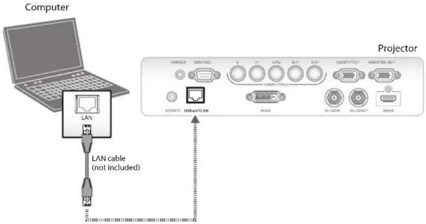
Compatible browsers are as follows.
Microsoft Internet Explorer 9 with Adobe Flash Player 9.0 or higher.
- On the PC (Laptop), select Start → Control Panel → Network and Internet.
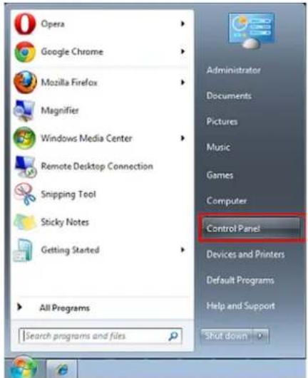
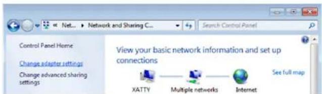
- Right-click on Local Area Connection, and select Properties.
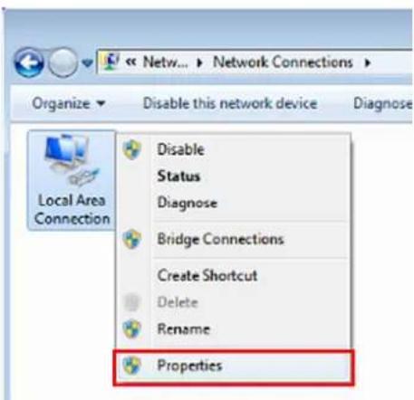
- In the Properties window, select the Networking tab, and select Internet Protocol (TCP/IP).
- Click Properties.
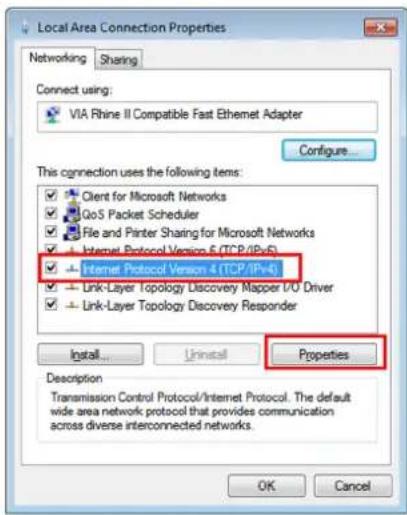
- Click Use the following IP address and fill in the IP address and Subnet mask, then click OK.
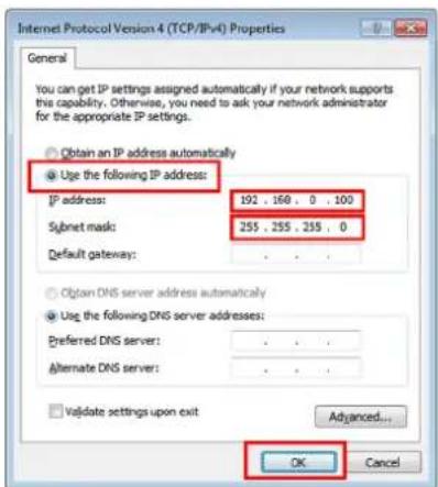
- Press the Menu button on the projector.
- Select CONTROL → Network.
- In Network, input the following:
■ IP Address: 192.168.0.100
■ Subnet Mask: 255.255.255.0
■ Gateway: 0.0.0.0
■ DHCP: Off
-
Press OK to confirm settings.
-
Open a web browser (for example, Microsoft Internet Explorer with Adobe Flash Player 9.0 or higher).
- In the Address bar, input the IP address: 192.168.0.100.
- Press OK.

The projector is setup for remote management. The LAN/RJ45 function displays as follows.
Based on network web-page for the input-string in tools tab, the limitation for Input-Length is in the below list ("space" and the other punctuation key included):
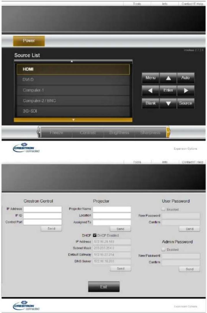
| Category Item Input-Length | ||
| Crestron Control IP Address | 15 | |
| IP ID 3 | ||
| Port 5 | ||
| Projector Projector Name 25 | ||
| Location 25 | ||
| Assigned To 25 | ||
| Network Configuration DHCP | (Enabled) (N/A) | |
| IP Address 15 | ||
| Subnet Mask 15 | ||
| Default Gateway 15 | ||
| DNS Server 15 | ||
| User Password Enabled (N/A) | ||
| New Password 18 | ||
| Confirm 18 | ||
| Admin Password Enabled (N/A) | ||
| New Password 18 | ||
| Confirm 18 | ||
For more information, please visit http://www.crestron.com/.
RS232 by Telnet Function
Besides projector connected to RS232 interface with "Hyper-Terminal" communication by dedicated RS232 command control, there is alternative RS232 command control way, so called "RS232 by TELNET" for LAN/RJ45 interface.
Quick Start Guide for "RS232 by TELNET"
Check and get the IP address on OSD of the projector.
Make sure that laptop/PC can access the web-page of the projector.
Make sure that "Windows Firewall" setting to be disabled in case of "TELNET" function filtering out by laptop/PC.
Start → All Programs → Accessories → Command Prompt
Input the command format as seen in the following:
telnet ttt.xxx.yyy.zzz 7000 ("Enter" key pressed)
(ttt.xxx.yyy.zzz: IP address of the projector)
If Telnet-Connection ready, and user can have RS232 command input, then "Enter" key pressed, the RS232 command will be workable.
How to have TELNET enabled in Windows VISTA / 7
By default installation for Windows VISTA, "TELNET" function is not included. But end-user can have it by way of "Turn Windows features On or Off" to be enabled.
- Open Control Panel in Windows VISTA.
- Open Programs.
- Select Turn Windows features on or off to open.
- Have Telnet Client option checked, then press OK button.
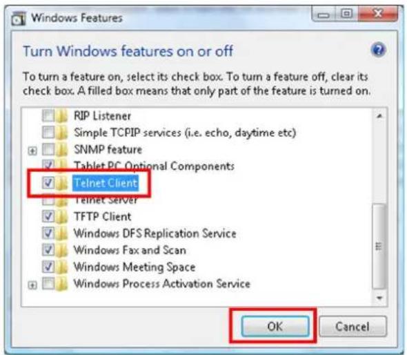
Specsheet for "RS232 by TELNET":
Telnet: TCP
Telnet port: 7000
■ Telnet utility: Windows "TELNET.exe" (console mode)
■ Disconnection for RS232-by-Telnet control normally: Close Windows Telnet utility directly after TELNET connection ready
■ Limitation 1 for Telnet-Control: there is only one connection for Telnet-Control in one projector. Limitation 2 for Telnet-Control: there is less than 50 bytes for successive network payload for Telnet-Control application.
Limitation 3 for Telnet-Control: there is less than 26 bytes for one complete RS232 command for Telnet-Control.
Limitation 4 for Telnet-Control: Minimum delay for next RS232 command must be more than 200 (ms).
(* In Windows built-in "TELNET.exe" utility, "Enter" key pressed will have "Carriage-Return" and "New-Line" code.)
Control ID Menu
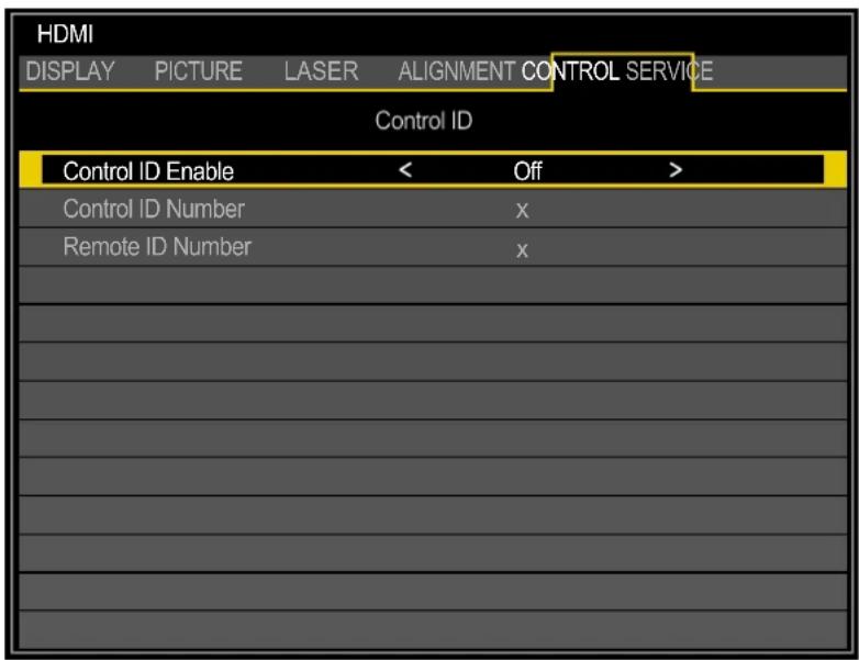
| Label Description | |
| Control ID Enable* Press | ◀ or ▶ to enable or disable control ID. |
| Control ID Number Press | ◀ or ▶ to set the control number for the projector. The function is only available when Control ID Enable is On.Press ENTER to apply Control ID setting. |
* To operate multiple projectors independently, set this ID function.
■ "Control ID" is for a projector.
■ "Remote ID" is for a remote control. See page 26.
SERVICE Menu
LX-MU800Z
| HDMI | |||
| DISPLAY | PICTURE | LASER | ALIGNMENT CONTROL SERVICE |
| Model Name | LX-MU800Z | ||
| Serial Number | DDE300001A | ||
| Software Version 1 | MM01-SD07-FD19 | ||
| Software Version 2 | LD06-22-RP02-3092 | ||
| Control / Remote ID | X / X | ||
| Active Source | HDMI | ||
| Signal Format | 1920x1200 60Hz RB | ||
| Pixel Clock | 154.00 MHz | ||
| H/V Refresh Rate | 74.038 KHz / 59.95 Hz | ||
| Laser Hours | 000100 HRS | ||
| Thermal Status | |||
| Factory Reset | |||
| Label Description | |
| Model Name Displays the projector model name. | |
| Serial Number Displays the projector serial number. | |
| Software Version 1 Displays the version of the installed software part I in the projector. | |
| Software Version 2 Displays the version of the installed software part II in the projector. | |
| Control / Remote ID Display the control ID / Remote ID. | |
| Active Source Displays the connected input signal. | |
| Signal Format Displays the signal format of the connected input signal. | |
| Pixel Clock Displays the pixel clock of the connected input signal. | |
| H/V Refresh Rate Displays the H/V refresh rate of the projected image. | |
| Laser Hours Displays the usage time of the projector. | |
| Thermal Status | Press ENTER to enter the Thermal Status menu. See “Thermal Status Menu” on page 79. |
| Factory Reset Press ENTER to restore the OSD to the default settings.Note:Factory Reset will not reset the following settings.High AltitudeProjection ModeCenter LensNetworkLanguageLaser Hours | |
LX-MU600Z
| HDMI | |||
| DISPLAY | PICTURE | LASER | ALIGNMENT CONTROL SERVICE |
| Model Name | LX-MU600Z | ||
| Serial Number | DEE300001A | ||
| Software Version 1 | MM01-SD07-FD19 | ||
| Software Version 2 | LD06-22-RP02-3092 | ||
| Control / Remote ID | X / X | ||
| Active Source | HDMI | ||
| Signal Format | 1920x1200 60Hz RB | ||
| Pixel Clock | 154.00 MHz | ||
| H/V Refresh Rate | 74.038 KHz / 59.95 Hz | ||
| Laser Hours | 000100 HRS | ||
| Thermal Status | |||
| Factory Reset | |||
| Label Description | |
| Model Name Displays the projector model name. | |
| Serial Number Displays the projector serial number. | |
| Software Version 1 Displays the version of the installed software part I in the projector. | |
| Software Version 2 Displays the version of the installed software part II in the projector. | |
| Control / Remote ID Display the control ID / Remote ID. | |
| Active Source Displays the connected input signal. | |
| Signal Format Displays the signal format of the connected input signal. | |
| Pixel Clock Displays the pixel clock of the connected input signal. | |
| H/V Refresh Rate Displays the H/V refresh rate of the projected image. | |
| Laser Hours Displays the usage time of the projector. | |
| Thermal Status | Press ENTER to enter the Thermal Status menu. See “Thermal Status Menu” on page 79. |
| Factory Reset Press ENTER to restore the OSD to the default settings.Note:Factory Reset will not reset the following settings.High AltitudeProjection ModeCenter LensNetworkLanguageLaser Hours | |
Thermal Status Menu
| HDMI | |||
| DISPLAY | PICTURE | LASER | ALIGNMENT CONTROL SERVICE |
| Thermal Status | |||
| Inlet Temperature | 25 / 25 ( C ) | ||
| DMD Temperature | 32 ( C ) | ||
| Laser Temperature | 33 / 30 ( C ) | ||
| Water Pump RPM | 3900 | ||
| Fan 1-3 Speed | 1400 / 1400 / 1400 | ||
| Fan 4-6 Speed | 1400 / 1200 / 1200 | ||
| Fan 7-9 Speed | 1200 / 1400 / 1400 | ||
| Fan 10-12 Speed | 0 / 3000 / 3000 | ||
| Fan 13-15 Speed | 3000 / 3000 / 3000 | ||
| Fan 16 Speed | 3000 | ||
| Label Description | |
| Inlet Temperature Display the inlet temperature. | |
| DMD Temperature Display the DMD temperature. | |
| Laser Temperature Display the laser temperature. | |
| Water Pump RPM Display the water pump rotation speed. | |
| Fan 1-3 Speed Display the fan 1-3 speed. | |
| Fan 4-6 Speed Display the fan 4-6 speed. | |
| Fan 7-9 Speed Display the fan 7-9 speed. | |
| Fan 10-12 Speed Display the fan 10-12 speed. | |
| Fan 13-15 Speed Display the fan 13-15 speed. | |
| Fan 16 Speed Display the fan 16 speed. | |
Maintenance and Security
Replacing the Projection Lamp
Do not attempt to replace the projection lamp yourself. Be sure to request this service from a qualified technician or contact the Canon Customer Support Center.
Make sure to use the exclusive optional lens.
There are following mentions in the zoom ring of the exclusive lens
■ DLP PROJECTION LENS Throw Ratio = 1.73-2.27:1 (WUXGA) (example)
- A proper power-off procedure requires that you turn off the projector, wait for the power LED to run solid red and disconnect the power plug from the wall outlet. Failure to do so,
■ an unexpected projection of light may cause injury to eyes.
■ it may result in electric shock.
- Remove the anti-theft screw for lens on the underside of the projector. See the following figure for a reference to the location.
Anti-theft screw for lens
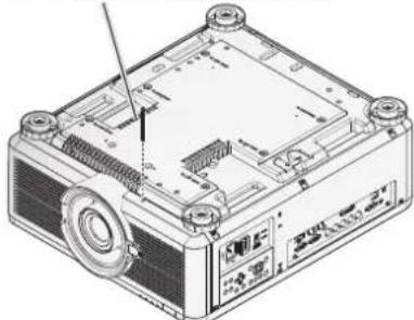
natural_image
Technical line drawing of a computer monitor base with ventilation slots and an antenna (no text or symbols)- Press the release button and support the old lens with a hand.
-
Turn the old lens counterclockwise to loosen.
-
Remove the old lens from the holder.
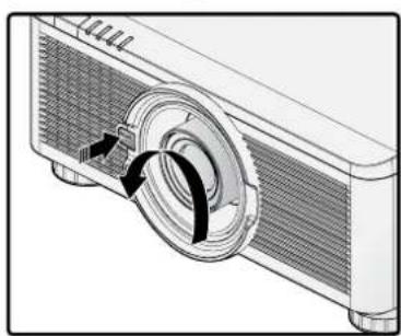
natural_image
Diagram of a projector with a circular component and directional arrows indicating rotation (no text or symbols)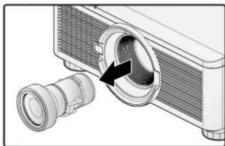
natural_image
Diagram of a projector with a lens inserted into a chamber, showing internal components and an arrow indicating direction (no text or symbols present)- Clean the new lens before installing. Take care when cleaning to prevent scratching the surface of the new lens.
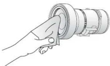
natural_image
Illustration of a hand inserting a cylindrical component into a ring (no text or symbols)-
Orient the lens so that the arrow on the label pasted on its side is facing upward and push the lens into the lens mount of the unit as far as it will go.
-
Turn the new lens clockwise until and audible Click is heard signifying the new lens is secured and seated correctly.
-
Gently pull on the new lens to ensure it is locked in place. If the new lens does not come off, it is seated correctly.
-
Install the anti-theft screw for lens to prevent removal of the lens. See "Using the Anti-theft Screw for Lens" on page 29.
Note:
■ Make sure you press and hold the release button to loosen and unlock the old lens from the projector when removing the old lens.
■ Be sure to execute Center Lens after the lens is changed.
■ Do not adjust lens manually (except LX-IL01UW).
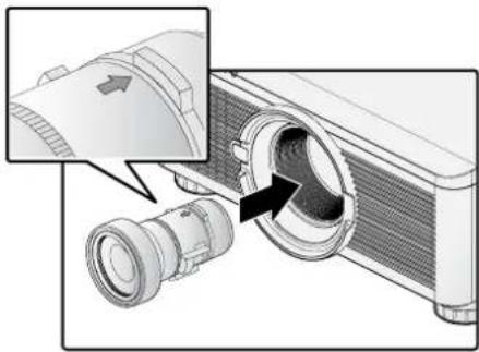
natural_image
Diagram of a projector with a close-up view showing internal components (no text or symbols)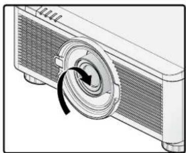
natural_image
Diagram of a projector with a circular component and arrow indicating rotation (no text or symbols)Cleaning the Projector
Cleaning the projector to remove dust and grime will help ensure trouble-free operation.
Warning:
Be sure to turn off the power and disconnect the power plug from the wall outlet. Failure to do so,
■ an unexpected projection of light may cause injury to eyes.
■ it may result in electric shock.
Cleaning the Cabinet
- Turn off the projector before cleaning.
- Use a vacuum cleaner to vacuum the dust inside.
- Use a dry soft cloth to wipe dust off the cabinet.
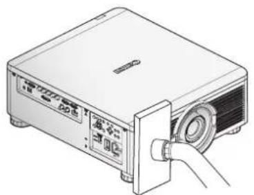
natural_image
Illustration of a projector with a cable inserted, showing no text or symbols on the device itself.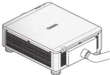
natural_image
Line drawing of a rectangular electronic device with ventilation grilles and a cable inserted (no text or symbols)Note:
Turn on the projector after cleaning the cabinet.
Cleaning the Lens
You can purchase optic lens cleaner from most camera stores. Refer to the following to clean the projector lens.
Caution:
- Do not use abrasive cleaners or solvents.
-
To prevent discoloration or fading, avoid getting cleaner on the projector case.
-
Turn off the projector before cleaning.
- Apply a little optic lens cleaner to a clean soft cloth. (Do not apply the cleaner directly to the lens.)
- Lightly wipe the lens in a circular motion.
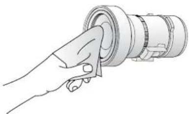
natural_image
Illustration of a hand holding a cylindrical mechanical component (no text or symbols visible)Using the Kensington® Lock
If you are concerned about security, attach the projector to a permanent object with the Kensington slot and a security cable.
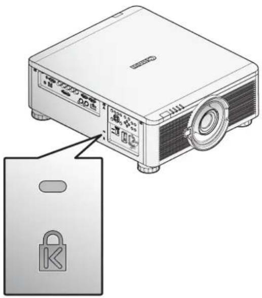
natural_image
Illustration of a projector with a lock icon and label, showing front panel and control buttons (no text or symbols on the device itself)Note:
Contact your vendor for details on purchasing a suitable Kensington security cable.
Ceiling Attachment Installation
The ceiling attachment is used to secure the projector to the ceiling. With the ceiling attachment, the projector cannot project an image upward or downward. Please refer to this section when you assemble and install the ceiling attachment.

Warning
Make sure the followings when you install and handle the ceiling attachment. Otherwise, it may result in fire, electric shock or injury.
■ Make sure to prepare stable scaffolding when installing the ceiling attachment.
■ Make sure to fully insert the power plug and connectors when connecting the projector. Never use a damaged plug or loosen outlet.
■ Make sure to tighten screws for the ceiling attachment securely and never loosen or remove them.
■ Never look into a lens when adjusting the projection because a high-intensity light is projected from the projector. It may result in eye damage.
■ During projection, never put an object in front of the projector's lens.

Caution
Make sure the followings when you install and handle the ceiling attachment.
■ Make sure to ask the Canon Customer Support Center if you want to install the ceiling attachment. An inappropriate installation may cause an accident.
Parts Lineup
The ceiling attachment RS-CL15 is for LX-MU800Z / LX-MU600Z.
Supplied Parts
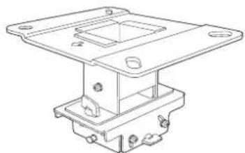
natural_image
Technical line drawing of a mechanical bracket assembly (no text or symbols)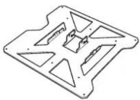
natural_image
Technical line drawing of a mechanical housing or bracket (no text or symbols)Ceiling-mount bracket and joint fitting* Base bracket
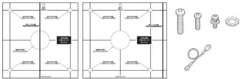
RS-CL15
M6 screw (25 mm/1.0") : 4 pcs.
M5 screw (12 mm/0.5") : 4 pcs
M4 screw (15 mm/0.6") : 10 pcs.
Anti-fall wires: 2 pcs.
Washer (Toothed Lock Washer): 1 pc.
Assembly/Installation Manual (This Manual): 1
Template sheet for a ceiling-mount hole: 2 shts.
* The ceiling-mount bracket must be separated from the Joint fitting, before installation.
Extension Pipe RS-CL08 / RS-CL09 (Optional)
Use an optional extension pipe (RS-CL08 / RS-CL09) according to the ceiling height. For details, contact our local agent.
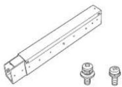
natural_image
Technical line drawing of a mechanical component with two separate bolted features (no text or symbols)RS-CL08
Outer/inner pipes and outer/inner covers M5 screw (12 mm/0.5"): 4 pcs.
M3 screw (10 mm/0.4"): 1 pc.
The length is adjustable between 35 cm/1.1' and 55 cm/1.9' in steps of 5 cm/0.2'.
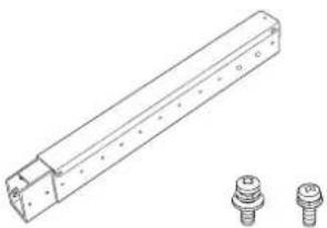
natural_image
Technical line drawing of a mechanical component with two separate bolted features (no text or symbols)RS-CL09
Outer/inner pipes and outer/inner covers M5 screw (12 mm/0.5"): 4 pcs.
M3 screw (10 mm/0.4"): 1 pc.
The length is adjustable between 55 cm/1.9' and 95 cm/3.1' in steps of 5 cm/0.2'.
Mounting Position
Install the projector straight in front of the screen. You can adjust the screen position using the lens shift feature.
Caution:
■ Before mounting the ceiling attachment, be sure to check the strength of the ceiling. The ceiling should be strong enough to support the projector and ceiling attachment (and optional extension pipe). If the ceiling is not strong enough, be sure to reinforce it. The projector may fall and you may get injured.
■ Make sure to perform the installation operation by at least two persons. Please be careful not to drop any object and pinch a finger during the installation operation.
■ To prevent falling caused by earthquake or vibration, take anti-fall measures using tension wires or the like for installation. The projector may fall and you may get injured.
At least 30 cm (0.98') around the intake and 50 cm (1.64') around the vent should be clear. Otherwise, it may damage the projector due to bad exhaust ventilation.
Installation Dimensions
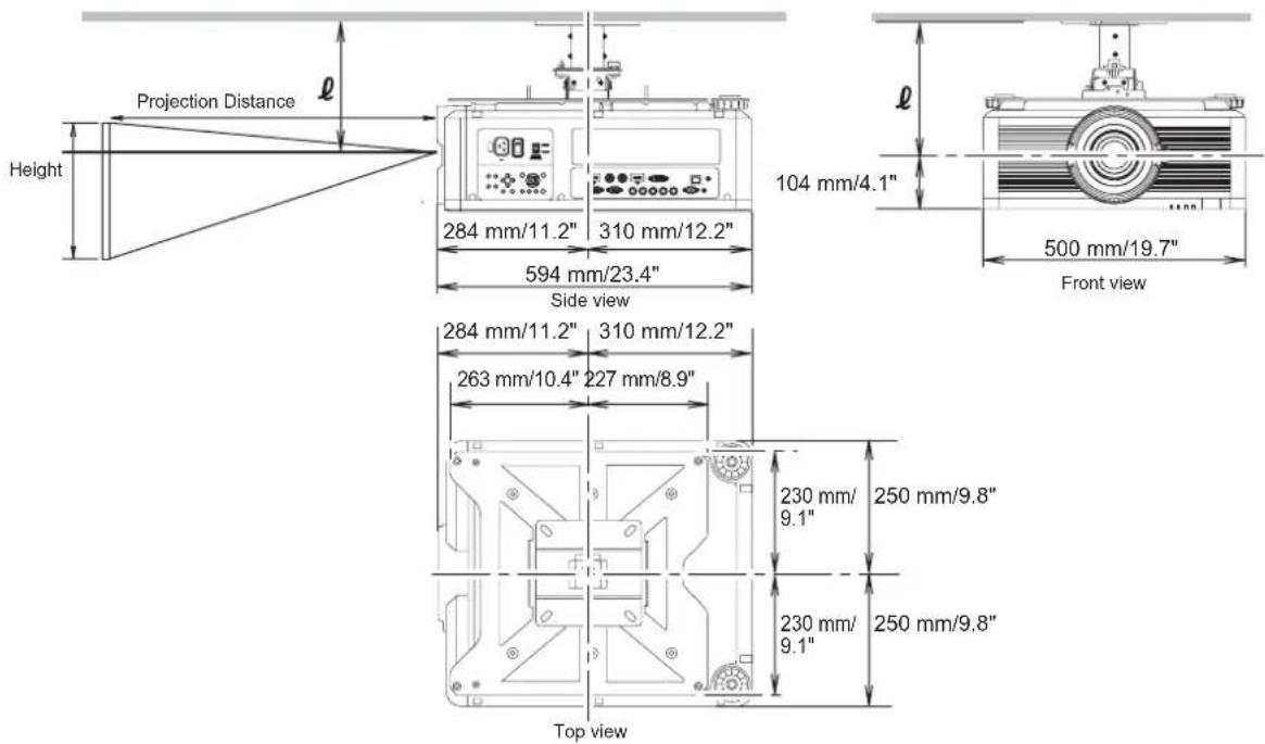
Distance from Ceiling to Lens Center (ℓ)
| RS-CL15 When RS-CL08 is used When RS-CL09 is used | |
| 26.2 cm / 0.9' 61.2 cm / 2.0' to 81.2 cm / 2.7' 81.2 cm / 2.7' to 121.2 cm / 4.0' |
For more detailed information on the screen sizes and the projection distance, see "Relationship Between Image Size and Projecting Distance" on page 96.
Ceiling-mount Bracket
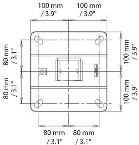
Assembly and Installation
Installation to Flat and Level Ceiling
Preparation:
Remove four M5 screws to separate joint fitting from the ceiling-mount bracket.
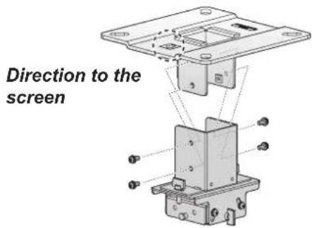
- Make a hole in the ceiling to install the ceiling-mount bracket and cables.
Caution:
■ Mounting position varies on the projector used. Make sure that the template sheet (A) corresponding to the projector is used.
■ When determining the hole position, use the supplied template sheet (A).
■ The direction to the screen is indicated on the template sheet (A).
- Use four M13 screws, to secure the ceiling-mount bracket to the ceiling with the arrow facing toward the screen.
■ Before securing the ceiling-mount bracket, be sure to remove the template sheet (A).
■ The M13 screws are not included in the supplied parts. Prepare the M13 screws suitable for the ceiling structure.
Direction to the screen
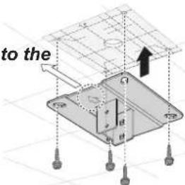
- Turn the projector base up, and remove the two adjusting legs on front side.
- Install the attached M4 screws at the six screw fastening positions on the Base bracket.
Caution:
■ Make sure to remove the adjusting foot before attaching the screw to the front part of the projector.
■ Be sure to keep the removed adjusting foot safely for later use.
- Secure the terminal clamp of the Anti-fall wire with the attached M4 screw at (A) on the Base bracket.
Make sure to fasten and tighten the screw securely.
- Pull cables out of the cable hole in the ceiling.
■ As depicted in the diagram, let cables pass through the hole on ceiling-mount clamp.
■ If cables are too thick, make a hole at a different position than the hole on the ceiling-mount clamp, and let them pass through the new hole.
-
Secure the ceiling-mount bracket using the four M5 screws removed during preparation.
-
Hook the base bracket on the protrusion (A) of the joint fitting, and secure it temporarily using the four supplied M5 screws (B).
- Mount the terminal clamp on the other end of anti-fall wire to the Joint fitting (C), and secure it at the wire-attaching position using M4 screw.
■ Pull out the cables.
■ Be sure to secure screws (B) tightly after making the adjustment discussed in "Adjust the Projection Angle" on page 91.
- Connect the cables to the projector.
After completion of installation, adjust the projection angle (page 91).
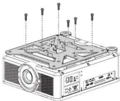
natural_image
Exploded view diagram of a projector with screw holes and control panel (no text or labels)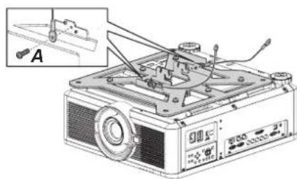
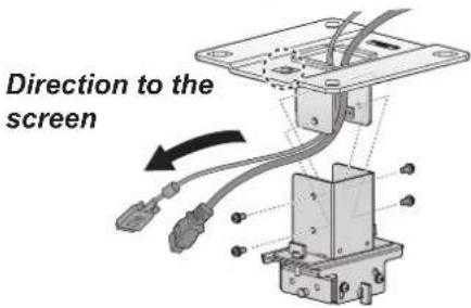
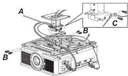
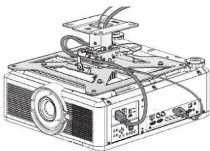
natural_image
Technical line drawing of an industrial projector with visible circuitry and control panel (no text or symbols)Installation to a High Ceiling
Use optional extension pipe RS-CL08 or RS-CL09 for high ceiling.
Preparation:
- Remove the covers of outer and inner pipes by slightly sliding them and lift up as shown.
- Remove four M5 screws from the sides of the outer pipe, adjust the inner pipe length according to the projector installation height, and then secure the four M5 screws.
When attaching screws in step 2, insert the screws and leave an unused screw hole between them. When the extension pipe is stretched to its maximum length, insert the screws in two adjacent screw holes.
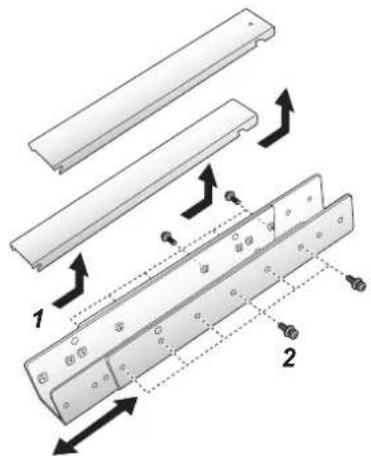
Extended length when extension pipe is attached (when lens shift is 0%)
| Mounting hole position | Distance from ceiling to lens axis (l) | |
| RS-CL08 RS-CL09 | ||
| a 61.2 cm/ | 2.0' 81.2 cm/2.7' | |
| b 66.2 cm/ | 2.2' 86.2 cm/2.8' | |
| c 71.2 cm/ | 2.3' 91.2 cm/3.0' | |
| d 76.2 cm/ | 2.5' 96.2 cm/3.2' | |
| e 81.2 cm/ | 2.7' 101.2 cm/3.3' | |
| f - 106.2 cm/ | 3.5' | |
| g - 111.2 cm/ | 3.6' | |
| h - 116.2 cm/ | 3.8' | |
| i - 121.2 cm/ | 4.0' | |
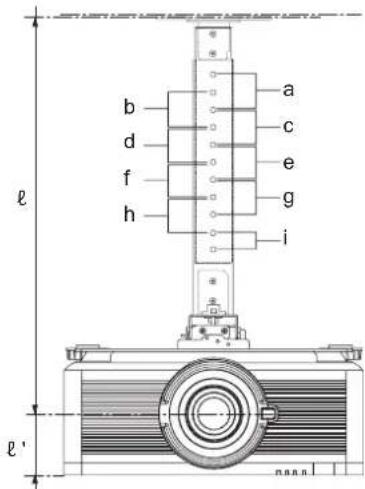
* To use the extension pipe with it extended to the maximum length, secure it by inserting screws in the two adjacent screw holes.
$$ \ell^ {\prime} = 1 0. 4 \mathrm{cm} / 0. 3 ^ {\prime} $$
Preparation:
Remove four M5 screws to separate joint fitting from the ceiling-mount bracket.
Direction to the screen
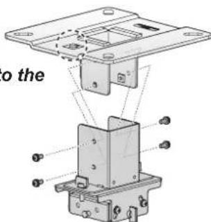
- Make a hole in the ceiling to install the ceiling-mount bracket and cables.
Caution:
■ Mounting position varies on the projector used. Make sure that the template sheet (A) corresponding to the projector is used.
■ When determining the hole position, use the supplied template sheet (A).
■ The direction to the screen is indicated on the template sheet (A).
- Use four M13 screws, to secure the ceiling-mount bracket to the ceiling with the arrow facing toward the screen.
■ Before securing the ceiling-mount bracket, be sure to remove the template sheet (A).
■ The M13 screws are not included in the supplied parts. Prepare the M13 screws suitable for the ceiling structure.
- Turn the projector base up, and remove the two adjusting legs on front side.
- Install the attached M4 screws at the six screw fastening positions on the Base bracket.
Caution:
■ Make sure to remove the adjusting foot before attaching the screw to the front part of the projector.
■ Be sure to keep the removed adjusting foot safely for later use.
- Secure the terminal clamp with the attached M4 screw at (A) on the Base bracket.
Make sure to fasten and tighten the screw securely.
- Secure to the extension pipe using the four supplied M5 screws.
The open end of the pipe should face the open end of the ceiling-mount bracket as shown.
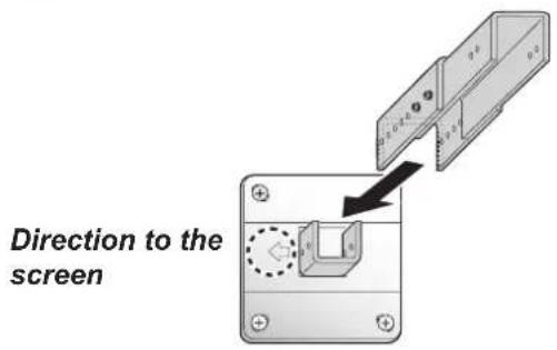
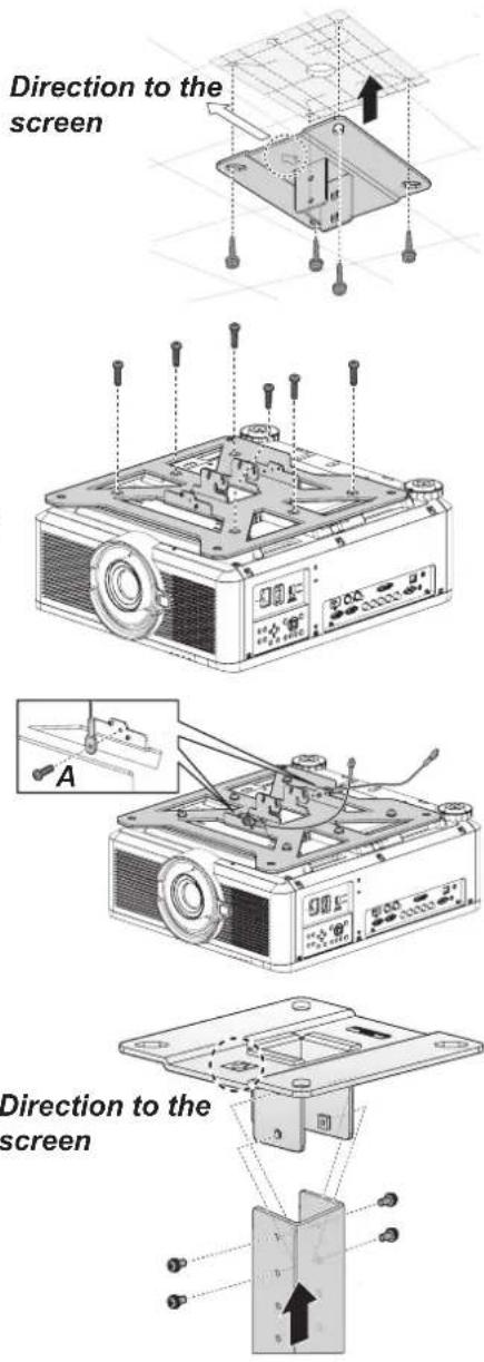
-
Use the four M5 screws removed from the ceiling-mount bracket during preparation.
-
Hook the base bracket on the protrusion (A) of the joint fitting, and secure it temporarily using the four supplied M5 screws (B).
- Mount the terminal clamp on the other end of anti-fall wire to the joint fitting (C), and secure it at the wire-attaching position using M4 screw.
■ Pull out the cables.
■ Be sure to secure screws (B) tightly after making the adjustment discussed in "Adjust the Projection Angle" on page 91.
- Pull the cables out of the cable hole in the ceiling.
- Put the cables inside the pipe.
- Close the inner cover of the pipe and then close outer cover of the pipe. Secure to the extension pipe using the supplied M3 screw.
- Connect the cables to the projector.
After completion of installation, adjust the projection angle (page 91).
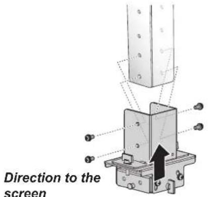
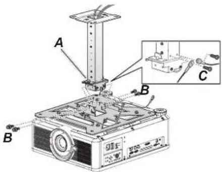
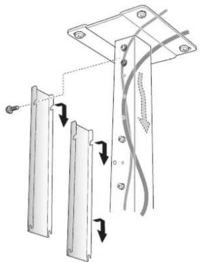
natural_image
Diagram of a mechanical assembly with two vertical panels and a connecting rod, showing directional arrows (no text or symbols)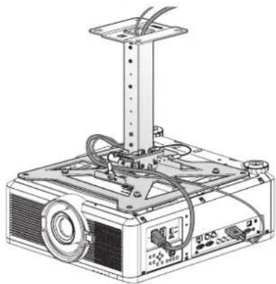
natural_image
Technical line drawing of a projector with mounted components and wiring (no text or symbols)Adjust the Projection Angle
Turn on the projector, project an image, and then adjust the projection angle and screen slant angle.
Caution:
■ After completion of adjustment, tighten the screws and check that every fitting is secured firmly.
■ Be sure to hold the projector from falling until the ceiling-mount bracket and Base bracket are secured firmly.
Adjust the horizontal projection angle
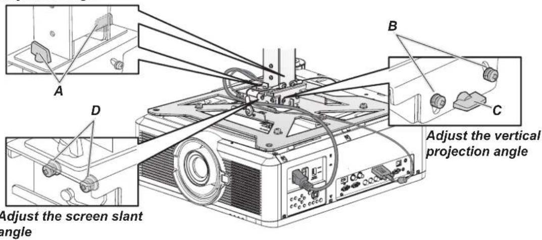
Adjust the Horizontal Projection Angle
- Loosen two wing screws (A). Move the projector horizontally to adjust the horizontal projection angle.
- When the projector is correctly positioned, tighten the wing screws.
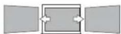
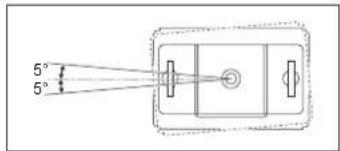
Adjust the Vertical Projection Angle
- First loosen four screws (B) and then loosen two wing screws (C). Move the projector vertically to adjust the vertical projection angle.
- When the projector is correctly positioned, first tighten the wing screws (C) and next tighten the four screws (B).
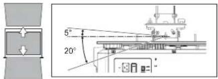
Adjust the Screen Inclination
- Loosen four screws (D), and then adjust the slant angle of the projector.
- When the projector is correctly positioned, tighten the four screws (D).
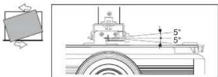
Specifications
RS-CL15
| Adjustment range | Horizontal projection angle 5° leftward or rightward | |
| Vertical projection angle 5° upward or 20° downward | ||
| Screen slant angle ± 5° | ||
| Outer dimension of assembly (excluding projection) (W x D x H) | 460 x 490 x 152.6 mm (18.1 x 19.3 x 6.0 in) | |
| Weight (Ceiling attachment only) 6.9 kg (15.2 lbs) | ||
Image Problems
Problem: No image appears on the screen.
- Check whether the projector is connected to the computer or AV equipment correctly.
- Check whether the power cord is connected correctly.
- Turn first the projector and then the computer off and then back on again.
Problem: The image is blurred.
- Adjust the Focus on the projector.
- Press the AUTO PC button on the remote control.
- Ensure the projector-to-screen distance is within the specified range.
- Check that the projector lens is clean.
Problem: The image is wider at the top or bottom (keystone distortion).
- Position the projector so it is as perpendicular to the screen as possible.
- Use the Keystone button on the ALIGNMENT menu of the OSD.
Problem: The image is reversed.
Check the Projector Mode settings on the ALIGNMENT menu of the OSD.
Problem: The image is streaked.
- Adjust the VGA Setup settings on the PICTURE menu of the OSD to the default settings.
- To ensure the problem is not caused by a connected PC's video card, connect to another computer.
Problem: The image is flat with no contrast.
Adjust the Contrast setting on the PICTURE menu of the OSD.
Problem: The color of the projected image does not match the source image.
- Adjust the Gamma settings on the PICTURE menu of the OSD.
- Adjust the Color Temperature settings on the PICTURE menu of the OSD.
Remote Control Problems
Problem: The projector does not respond to the remote control.
- Direct the remote control towards remote sensor on the projector.
- Ensure the path between remote and sensor is not obstructed.
- Turn off any fluorescent lights in the room.
- Check the battery polarity.
- Replace the battery.
- Turn off other Infrared-enabled devices in the vicinity.
- Have the remote control serviced.
Having the Projector Serviced
If you are unable to solve the problem, you should have the projector serviced. Pack the projector in the original carton. Include a description of the problem and a checklist of the steps you took when trying to fix the problem: The information may be useful to service personnel. For servicing, return the projector to the place you purchased it.
Product Specifications
| Model name LX-MU800Z LX-MU600Z | |||
| Display system 1-CHIP DLPTM | |||
| Display device | Type DMD | ||
| Size / Aspect ratio 0.67"x1 / 16:10 | |||
| Drive system DLPTM x 1 chip | |||
| Number of pixels 2,304,000 (1920 x 1200) x 1 | |||
| Projection lens (*1) (*2) | Zoom ratio / Focal length / F number | 1.3x / f = 26 to 34mm / F = 1.64 to 1.86 | |
| Zooming / Focusing system Electric / Electric | |||
| Lens shift (motorized) Adjust range: V (down: 30% ~ up: 60%), H (left: 10% ~ right: 20%) Optical performance guaranteed range: V (down: 0% ~ up: 50%), H (left: 10% ~ right: 10%) | |||
| Keystone correction Horizontal: +/-60°, shift is set to 0% (center). | |||
| Light source Laser Diode | |||
| Image size (projection distance) (*1) (*2) | 50" to 300" (1.83m to 14.9m / 6' to 49') | ||
| Number of colors 1.07 billion colors | |||
| Brightness (*1) (*2) (*3) 8000 lumen | (in presentation mode) | 6800 lumen (in presentation mode) | |
| Contrast ratio (with Dynamic Black on) (*1) (*2) | 10500:1 (Fully white: Fully black, in presentation mode) | ||
| Display scanning frequency H: 15 to 108 kHz, V: 48-120 Hz | |||
| Maximum input resolution 1920 x 1200 dots | |||
| Image signal | Digital PC | WUXGA (RB) / WSXGA+ / UXGA / SXGA+ / WXGA + / SXGA / XGA / SVGA / VGA | |
| Analog PC WUXGA (RB) / W | SXGA+ / UXGA / SXGA+ / WXGA+ / WXGA / SXGA / XGA / SVGA / VGA | ||
| Digital video | 1080p / 1080i / 720p / 576p / 480p | ||
| Component video | 1080p / 1080i / 720p / 576p / 480p / 576i / 480i | ||
| HDBaseT | Same as the Digital PC and Digital video | ||
| 3G-SDI | Same as the Digital PC and Digital video | ||
| Terminals | HDMI | Digital PC / Digital video input | |
| DVI-D | Digital PC / Digital video input | ||
| RJ45 | HDBaseT input / Network connection | ||
| 5BNC Analog PC / Component video input | |||
| Dsub15 | Analog PC input | ||
| Dsub15 (output) | Connect to a Display with Analog RGB input | ||
| 3G-SDI | Connect a BNC cable from Serial Digital Interface Device | ||
| 3G-SDI (output) | Connect to a Display with Series Digital Interface input | ||
| Dsub9 | RS-232 (serial communication) | ||
| Mini pin jack | Connect to a wired remote | ||
| Mini pin jack | 12 V output (trigger for screen operation) | ||
| Acoustic Noise (Normal / ECO) 40dB / 37dB | |||
| Operating temperature 5°C (41°F) to 40°C (104°F), RH 10~85% | |||
| Power supply AC 100-130V, 200-240V selectable | |||
| Maximum power consumption 890W/845W (100V/240V) 725W/695W (100V/240V) | |||
| Standby mode power consumption ECO: < 0.5W (only for Remote/Power Button) Networking: < 6W (only for Remote/Power Button/LAN) | |||
| Dimensions (W x D x H) 500 x 594 x 216 mm (19.68 x 23.38 x 8.5 in), including protrusion | |||
| Weight (excluding the lens) 28 kg (61.73 lbs) | |||
| Accessories Remote control, Remote control two dry-cell batteries, Power cord, Computer cable, Dust cap, User manual CD, Anti-theft screw for lens, Important Information, Warranty card | |||
(*1) Compliance with ISO21118-2012.
(*2) When using a Standard Zoom Lens (LX-IL03ST).
(*3) There is a function that automatically limits the brightness when the projector is used in a hot environment.
(*4) When using LX-IL01UW/LX-IL07WF, correction range will be limited to +/-33°.
Product specifications and appearance are subject to change without notice.
Projector Dimensions
LX-MU800Z / LX-MU600Z
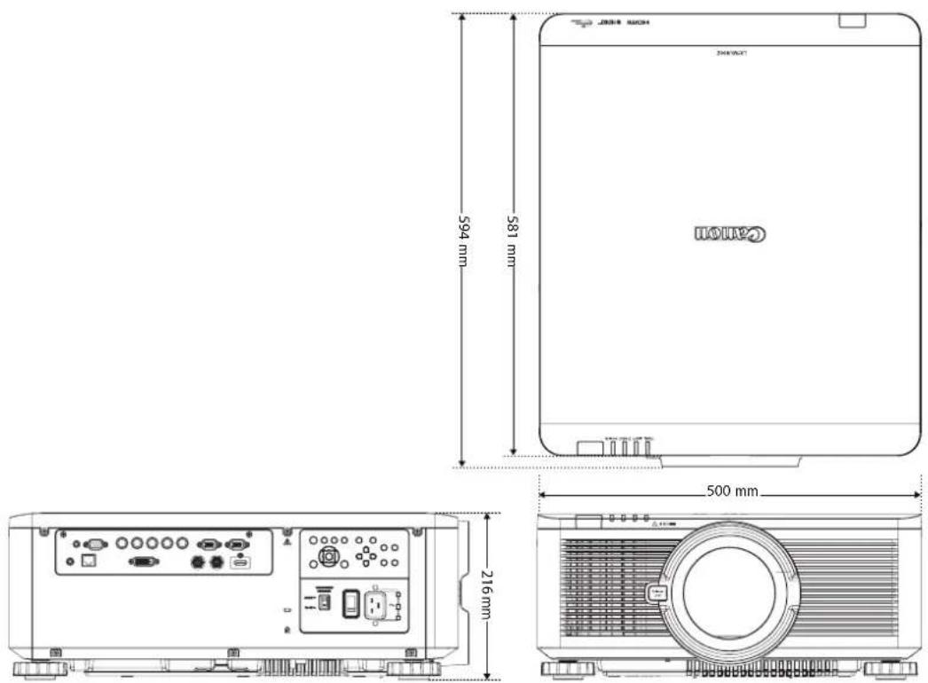
Relationship Between Image Size and Projecting Distance
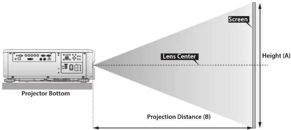
| Lens Unit LX-IL01UW LX-IL02WZ | ||||||||||||
| Lens Type | Ultra wide zoom lens Wide zoom lens | |||||||||||
| Throw Ratio 0.75 ~ 0.93 : 1 1.25 ~ 1.79 : 1 | ||||||||||||
| Image Size Projection Distance (B) | ||||||||||||
| Diagonal Width Height (A) | Wide Tele Wide Tele | |||||||||||
| (inch) | (m) (inch) | (m) (inch) | (m) (inch) | (inch) (m) | (inch) | (m) (inch) | (m) (inch) | (m) | ||||
| 40 1.02 | 34 0.86 | 21 0.54 | 24.5 0.62 | 31.1 0.79 | 41.4 1.00 | 59 1.05 | 9 1.52 | |||||
| 50 1.27 | 42 1.08 | 26 0.67 | 31.1 0.79 | 39.2 1.00 | 52.3 1.33 | 75 1.33 | 1.92 | |||||
| 60 1.52 | 51 | 1.29 32 | 0.81 | 96 37.6 | 96 | 47.4 1.20 | 63.1 | 1.60 90.9 | 2.31 | |||
| 80 | 2.03 63 | 1.72 42 | 1.08 50 | 1.29 63.8 | 1.62 84.9 | 2.16 | 121.8 | 3.09 | ||||
| 100 2 | 54 85 2 | 15 53 1.35 | 63.9 1.62 | 80.2 2.04 | 106 6.6 | 2.71 | 152.7 | 3.88 | ||||
| 120 3 | 05 102 2 | 2.58 64 1.62 | 77.1 1.96 | 96 6 | 2.45 128.4 | 3.26 | 183.6 | 4.66 | ||||
| 150 3 | 81 127 3 | 23 79 2 | 96.8 2.46 | 121.1 | 3.08 | 4.09 | 230.0 | 5.84 | ||||
| 180 4 | 57 153 3 | 88 95 2 | 116.5 2.96 | 145.7 | 3.70 | 4 | 92 276.4 | 7.02 | ||||
| 200 5 | 08 170 4 | 31 106 | 129 2.69 | 3.29 | 4.1 | 5.47 | 307.3 | 7.81 | ||||
| 300 7 | 62 254 6 | 46 159 | 195 4.04 | 4.96 | 6.20 | 324.0 | 8.23 | 461.9 | 11.73 | |||
| 400 | 10.16 | 339 | 8.62 | 212 | 5.38 | 6.63 | 325.9 | 8.28 | 432.7 | 10.99 | 616.6 | 15.66 |
| 500 | 12.70 | 424 | 10.77 | 265 | 6.73 | 8.30 | 407.7 | 10.36 | 541.5 | 13.75 | 771.2 | 19.59 |
* The table indicates projection range, optical performance is only guaranteed from 50 to 300 inches.
| Lens Unit LX-IL03ST LX-IL04 | MZ | ||||||||||||
| Lens Type Standard zoom lens | Middle zoom lens | ||||||||||||
| Throw Ratio 1.73 ~ 2.27 : 1 2.22 ~ 3.67 : 1 | |||||||||||||
| Image Size Projection Distance (B) | |||||||||||||
| Diagonal Width Height (A) | Wide Tele | Wide Tele | |||||||||||
| (inch) | (m) | (inch) | (m) | (inch) | (inch) | (inch) | (inch) | (inch) | (inch) | ||||
| 40 | 1.02 | 34 | 0.8 | 6 | 21 | 0.5 | 4 | 57.2 | 1.45 | 75.8 | 1.93 | 73.6 | 1.87 |
| 50 | 1.27 | 42 | 1.0 | 8 | 26 | 0.6 | 7 | 72.1 | 1.83 | 95.5 | 2.42 | 92.9 | 2.36 |
| 60 | 1.52 | 51 | 1.29 | 32 | 0.81 | 87.1 | 2.21 | 115.1 | 2.92 | 112.1 | 2.85 | 187.8 | 4.77 |
| 80 | 2.03 | 68 | 1.72 | 42 | 1.08 | 117.0 | 2.97 | 154.3 | 3.92 | 150.5 | 3.82 | 251.4 | 6.39 |
| 100 | 2.54 | 85 | 2.15 | 53 | 1.35 | 147.0 | 3.73 | 193.5 | 4.92 | 188.9 | 4.80 | 315.0 | 8.00 |
| 120 | 3.05 | 102 | 2.58 | 64 | 1.62 | 176.9 | 4.49 | 232.8 | 5.91 | 227.6 | 5.78 | 378.6 | 9.62 |
| 150 | 3.81 | 127 | 3.23 | 79 | 2.02 | 221.8 | 5.63 | 291.6 | 7.41 | 285.0 | 7.24 | 474.1 | 12.04 |
| 180 | 4.57 | 153 | 3.88 | 95 | 2.42 | 266.7 | 6.77 | 350.5 | 8.90 | 342.6 | 8.70 | 569.5 | 14.47 |
| 200 | 5.08 | 170 | 4.31 | 106 | 2.69 | 296.6 | 7.53 | 389.7 | 9.90 | 381.0 | 9.68 | 633.1 | 16.08 |
| 300 | 7.62 | 254 | 6.46 | 159 | 4.04 | 446.3 | 11.34 | 585.9 | 14.90 | 573.2 | 14.56 | 951.2 | 24.16 |
| 400 | 10.16 | 339 | 8.62 | 212 | 5.38 | 595.9 | 15.14 | 782.3 | 19.87 | 765.3 | 19.44 | 1269.7 | 32.25 |
| 500 | 12.70 | 424 | 10.77 | 265 | 6.73 | 745.6 | 18.94 | 978.3 | 24.85 | 957.4 | 24.32 | 1587.8 | 40.33 |
| Lens Unit | LX-IL05LZ | LX-IL06UL | |||||||||||
| Lens Type | Long zoom lens | Ultra long zoom lens | |||||||||||
| Throw Ratio | 3.58 ~ 5.38 : 1 | 5.31 ~ 8.26 : 1 | |||||||||||
| Image Size | Projection Distance (B) | ||||||||||||
| Diagonal Width Height (A) | Wide Tele | Wide | Tele | ||||||||||
| (inch) | (m) | (inch) | (m) | (inch) | (m) | (inch) | (m) | (inch) | (m) | (inch) | (m) | (inch) | (m) |
| 40 | 1.02 | 34 | 0.86 | 21 | 0.54 | 118.7 | 3.01 | 181.0 | 4.60 | 173.9 | 4.42 | 277.7 | 7.05 |
| 50 | 1.27 | 42 | 1.08 | 26 | 0.67 | 149.7 | 3.80 | 227.6 | 5.78 | 220.2 | 5.59 | 350.0 | 8.89 |
| 60 | 1.52 51 | 1.29 | 32 0.81 | 180.7 | 4.59 | 274.1 | 6.96 | 266.6 | 6.77 | 422.3 | 10.73 | ||
| 80 | 2.03 | 68 | 1.72 | 42 | 1.08 | 242.7 | 6.16 | 367.3 | 9.33 | 359.4 | 9.13 | 567.0 | 14.40 |
| 100 | 2.54 | 85 | 2.15 | 53 | 1.35 | 304.3 | 7.73 | 460.4 | 11.70 | 452.1 | 11.48 | 711.6 | 18.07 |
| 120 | 3.05 | 102 | 2.58 | 64 | 1.62 | 366.7 | 9.31 | 553.6 | 14.06 | 544.9 | 13.84 | 856.2 | 21.75 |
| 150 | 3.81 | 127 | 3.23 | 79 | 2.02 | 459.4 | 11.67 | 693.3 | 17.61 | 684.0 | 17.37 | 1073.1 | 27.26 |
| 180 | 4.57 | 153 | 3.88 | 95 | 2.42 | 552.4 | 14.03 | 833.0 | 21.16 | 823.1 | 20.91 | 1290.1 | 32.77 |
| 200 | 5.08 | 170 | 4.31 | 106 | 2.69 | 614.7 | 15.60 | 926.4 | 23.53 | 915.9 | 23.26 | 1434.7 | 36.44 |
| 300 | 7.62 | 254 | 6.46 | 159 | 4.04 | 924.0 | 23.47 | 1392.1 | 35.36 | 1379.6 | 35.04 | 2157.8 | 54.81 |
| 400 | 10.16 | 339 | 8.62 | 212 | 5.38 | 1233.9 | 31.34 | 1857.9 | 47.19 | 1843.3 | 46.82 | 2880.9 | 73.18 |
| 500 | 12.70 | 424 | 10.77 | 265 | 6.73 | 1543.7 | 39.21 | 2323.6 | 59.02 | 2307.1 | 58.60 | 3604.0 | 91.54 |
* The table indicates projection range, optical performance is only guaranteed from 50 to 300 inches.
| Lens Unit LX-IL07WF | |||||||
| Lens Type Short fixed | lens | ||||||
| Throw Ratio 0.76 : 1 | |||||||
| Image Size Projection | Distance (B) | ||||||
| Diagonal Width Height (A) | N/A | ||||||
| (inch) | (m) | (inch) | (m) | (inch) | (m) | ||
| 40 | 1.02 | 34 | 0.8 | 6 | 21 | 0.5 | 4 |
| 50 | 1.27 | 42 | 1.0 | 8 | 26 | 0.6 | 7 |
| 60 | 1.52 | 51 | 1.2 | 9 | 32 | 0.8 | 1 |
| 80 | 2.03 | 68 | 1.7 | 2 | 42 | 1.0 | 8 |
| 100 | 2.54 | 85 | 2.1 | 15 | 53 | 1.3 | 5 |
| 120 | 3.05 | 102 | 2.5 | 8 | 64 | 1.6 | 2 |
| 150 | 3.81 | 127 | 3.2 | 3 | 79 | 2.0 | 2 |
| 180 | 4.57 | 153 | 3.8 | 8 | 95 | 2.4 | 2 |
| 200 | 5.08 | 170 | 4.3 | 1 | 106 | 2.6 | 9 |
| 300 | 7.62 | 254 | 6.4 | 6 | 159 | 4.0 | 4 |
| 400 | 10.16 | 339 | 8.6 | 2 | 212 | 5.3 | 8 |
| 500 | 12.70 | 424 | 10.7 | 7 | 265 | 6.7 | 3 |
* The table indicates projection range, optical performance is only guaranteed from 50 to 300 inches.
Lens Series
| Part Number | Lens Name F Number | Number Focal | Length Zoom | Ratio | Screen Size | Throw Ratio | |
| WUXGA 16:10 | XGA 4:3 | ||||||
| LX-IL01UW | Ultra wide zoom lens | 1.96-2.3 | 11.3-14.1mm | 1.25:1 | 40"-500" | 0.75-0.93:1 | 0.77-0.97:1 |
| LX-IL02WZ | Wide zoom lens | 1.85-2.5 | 18.7-26.5mm | 1.41:1 | 40"-500" | 1.25-1.79:1 | 1.30-1.85:1 |
| LX-IL03ST | Standard zoom lens | 1.7-1.9 | 26-34mm | 1.3:1 | 40"-500" | 1.73-2.27:1 | 1.79-2.35:1 |
| LX-IL04MZ | Middle zoom lens | 1.86-2.48 | 32.9-54.2mm | 1.65:1 | 40"-500" | 2.22-3.67:1 | 2.30-3.81:1 |
| LX-IL05LZ | Long zoom lens | 1.85-2.41 | 52.8-79.1mm | 1.5:1 | 40"-500" | 3.58-5.38:1 | 3.71-5.51:1 |
| LX-IL06UL | Ultra long zoom lens | 1.85-2.48 | 78.5-121.9mm | 1.55:1 | 40"-500" | 5.31-8.26:1 | 5.50-8.56:1 |
| LX-IL07WF | Short fixed lens | 1.85 | 11.6mm | - | 40"-500" | 0.76:1 | 0.79:1 |
* The table indicates projection range, optical performance is only guaranteed from 50 to 300 inches.
LED Indicator Status
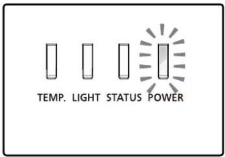
Power LED Indicator
| LED Display Projector Status | ||
| Off Power is off | ||
| Flashing Green | Prepare to turn on projector | |
| Orange Projector cooling | ||
| On Red Standby mode | ||
Status LED Indicator
| LED Display Projector Status | ||
| Off No problem | ||
| Flashing Red (Cycles of 1) Cover & lens switch problem | ||
| Red (Cycles of 4) Fan problem | ||
| On Red System error | ||
Light LED Indicator
| LED Display Projector Status | ||
| Off Laser off | ||
| Flashing Green | Prepare to light laser | |
| Red (Cycles of 6) Laser lit fail | ||
| On Green Laser | lit | |
Temperature LED Indicator
| LED Display Projector Status | |
| Off No problem | |
| Flashing Red Temperature problem | |
Supported Signal Input Timing
Computer
| Signal Type | Resolution Freq. H (KHz) | Freq. V (Hz) | Clock (MHz) | BNC - RGBHV | BNC - YUV | HD15 - RGBHV | HD15- YUV | DVI-D (EIA Timing) | HDMI RGB (EIA Timing) | HDMI YUV (EIA Timing) | HDBaseT | ||
| PC 640*480-60 31.47 59.93 | 25.175 V - V - V V - V | ||||||||||||
| 640*480-75 37.5 75 31.5 V - V - V V - V | |||||||||||||
| 640*480-85 43.27 85.01 36 V - V - V V - V | |||||||||||||
| 800*600-60 37.8 60.32 40 V - V - V V - V | |||||||||||||
| 800*600-75 46.8 75 49.5 V - V - V V - V | |||||||||||||
| 800*600-85 53.67 85.06 56.25 V - V - V V - V | |||||||||||||
| 848*480-60 31.02 60 33.75 V - V - V V - V | |||||||||||||
| 1024*768-60 48.36 60 | 65 V - V - V V - V | ||||||||||||
| 1024*768-75 60.02 75.03 78.75 V - V - V | |||||||||||||
| 1024-768-85 68.88 85.03 | 94.5 V - V - V V - V | ||||||||||||
| 1280*720-60 44.69 59.91 74.37 V - V - V | |||||||||||||
| 1280*768-60 47.8 59.87 | 79.5 V - V - V V - V | ||||||||||||
| 1280*800-60 49.702 59.81 83.5 V - V - V | |||||||||||||
| 1280*960-60 60 | 60 | 108 | V - V - V - V | ||||||||||
| 1280*1024-60 63.98 60.02 | 108 | V - V - V V - V | |||||||||||
| 1280*1024-75 79.98 75.02 | 135 | V - V - V V - V | |||||||||||
| 1280*1024-85 91.15 85.02 15 | 7.5 V - V - V | ||||||||||||
| 1366*768-60 47.71 59.79 85.5 V | V | V V | V | ||||||||||
| 1440*900-60 55.935 59.887 106.5 V - V - V V - V | |||||||||||||
| 1400X1050-60 | 65.517 59.98 121.75 | V - V - V V - V | |||||||||||
| 1600*1200-60 75 | 60 | 162 | V - V - V V - V | ||||||||||
| 1680*1050-59.94 | 65.179 | 59.94 | 146 | V | - | V | - | V | V | - | V | ||
| 1920*1200RB-60 | 74.04 | 59.95 | 154 | V | - | V | - | V | V | - | V | ||
| SDTV | 1440x480i | 15.73 | 60 | 27 | - | - | - | - | - | V | V | V (HDMI) | |
| 1440x576i | 15.62 | 50 | 27 | - | - | - | - | - | V | V | V (HDMI) | ||
| 480i | 15.734 | 59.94 | 13.5 | - | V | - | V | - | - | - | - | - | |
| 576i | 15.625 | 50 | 13.5 | - | V | - | V | - | - | - | - | - | |
| EDTV 480p 31.47 59.94 27 V V V V V V V | |||||||||||||
3D Signal Input Mode
| Timing Format | H Freq. | V Freq. | Pixel | H | H | H | H | H | V | V | V | V | Note | |
| (KHz) | (Hz) | Clock (MHz) | Total Pixel | Display Pixel | Front Porch | Sync | Back Porch | Total Lines | Display Lines | Front Porch | Sync | Back Porch | Auto | |
| 720p_50 | 37.5 | 50 | 74.25 | 1980 | 1280 | 440 | 40 | 220 | 750 | 720 | 5 | 5 | 20 | OK |
| 720p_60 | 45 | 60 | 74.25 | 1650 | 1280 | 110 | 40 | 220 | 750 | 720 | 5 | 5 | 20 | OK |
| 1080i_50 | 28.125 | 25 | 74.25 | 2640 | 1920 | 528 | 44 | 148 | 562 | 540 | 2 | 5 | 15 | OK |
| 1080i_60 | 33.75 | 30 | 74.25 | 2200 | 1920 | 88 | 44 | 148 | 562 | 540 | 2 | 5 | 15 | OK |
| 1080p_24 | 27 | 24 | 74.25 | 2750 | 1920 | 638 | 44 | 148 | 1125 | 1080 | 4 | 5 | 36 | OK |
| 1080p_50 | 56.25 | 50 | 148.5 | 2640 | 1920 | 528 | 44 | 148 | 1125 | 1080 | 4 | 5 | 36 | OK |
| 1080p_60 | 67.5 | 60 | 148.5 | 2200 | 1920 | 88 | 44 | 148 | 1125 | 1080 | 4 | 5 | 36 | OK |
* The following Timing Formats require 3D formats carrying InfoFrame packets (based on the HDMI 1.4a standard) from HDMI or HDBaseT sources only.
| Timing Format | 3D Format Support | ||
| FP SES | TAB | ||
| 720p_50 | V V V | ||
| 720p_60 | V V V | ||
| 1080i_50 | V | ||
| 1080i_60 | V | ||
| 1080p_24 | V V V | ||
| 1080p_50 | V | V | |
| 1080p_60 | V | V | |
3G-SDI
| Timing SD | Link Mode | Signal Standards Color | Encode Sampling Structure | Bit Depth | Remark |
| NTSC SD SM | PTE 259M-C | 270Mbps SD YCbCr 4:2:2 10 128M | |||
| PAL SD SMPTE | 259M-C 270Mbps SD YCbCr 4:2:2 10 128M | ||||
| 1035i60 HD S | MPTE 292M | 1.5Gbps HD YCbCr 4:2:2 10 128M | |||
| 1080i59 HD S | MPTE 292M | 1.5Gbps HD YCbCr 4:2:2 10 128M | |||
| 1080i60 HD S | MPTE 292M | 1.5Gbps HD YCbCr 4:2:2 10 128M | |||
| 1080P30 HD | SMPTE 292M | 1.5Gbps HD YCbCr 4:2:2 10 128M | |||
| 1080P25 HD | SMPTE 292M | 1.5Gbps HD YCbCr 4:2:2 10 128M | |||
| 1080i50 HD S | SMPTE 292M | 1.5Gbps HD YCbCr 4:2:2 10 128M | |||
| 1080P24 HD | SMPTE 292M | 1.5Gbps HD YCbCr 4:2:2 10 128M | |||
| 720P60 HD S | MPTE 292M | 1.5Gbps HD YCbCr 4:2:2 10 128M | |||
| 720P50 HD S | MPTE 292M | 1.5Gbps HD YCbCr 4:2:2 10 128M | |||
| 1080Sf25 | HD SMPTE 292M | 1.5Gbps HD YCbCr 4:2:2 10 128M | |||
| 1080Sf30 | HD SMPTE 292M | 1.5Gbps HD YCbCr 4:2:2 10 128M | |||
| 1080P50 | 3G Level A | SMPTE 424M 3Gbps | YCbCr | 4:2:2 | 10 |
| 1080P59 | 3G Level A | SMPTE 424M 3Gbps | YCbCr | 4:2:2 | 10 |
| 1080P60 | 3G Level A | SMPTE 424M 3Gbps | YCbCr | 4:2:2 | 10 |
| 1080P50 3G | Level B SMPTE 424M 3Gbps | YCbCr 4:2:2 10 128M | |||
| 1080P59 3G | Level B SMPTE 424M 3Gbps | YCbCr 4:2:2 10 128M | |||
| 1080P60 3G | Level B SMPTE 424M 3Gbps | YCbCr 4:2:2 10 128M | |||
Notes for Projection Mode
- Referring to the following illustration, select a Projection Mode in the ALIGNMENT menu. The options are Front Tabletop, Front Ceiling, Rear Tabletop and Rear Ceiling.
- When the projector is installed in a tilt angle over ±10 degrees, you need to select High at the High Altitude function in the LASER menu. This function sets the fan speed to high due to the high altitude environment.
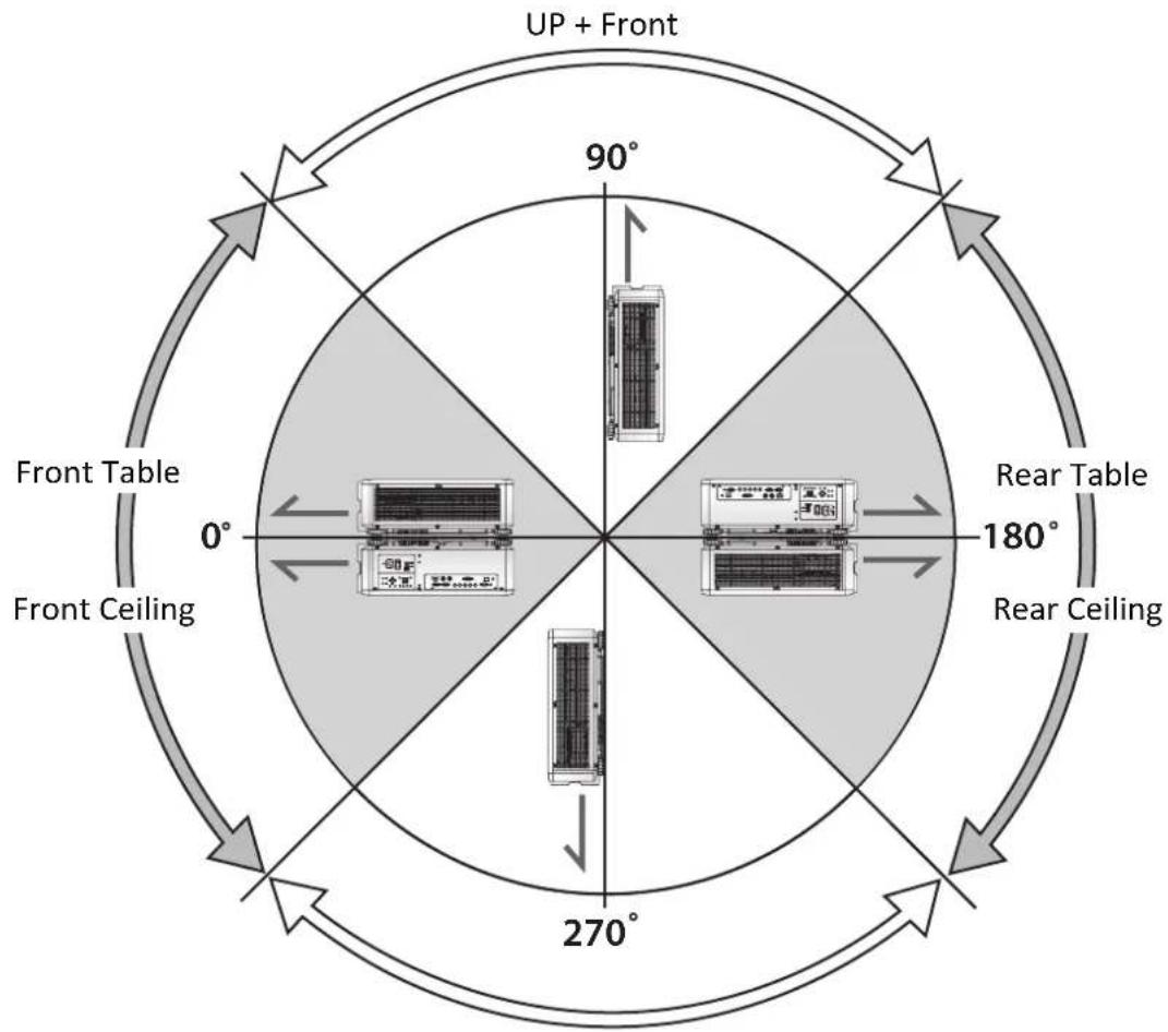
flowchart
graph TD
    A["Front Ceiling"] --> B["Up + Front"]
    B --> C["Rear Ceiling"]
    C --> D["Front Table"]
    D --> E["Up + Front"]
    E --> F["Rear Table"]
    F --> G["Front Ceiling"]
    G --> H["Up + Front"]
    H --> I["Rear Ceiling"]
    I --> J["Front Table"]
    style A fill:#f9f,stroke:#333
    style B fill:#ccf,stroke:#333
    style C fill:#cfc,stroke:#333
    style D fill:#fcc,stroke:#333
    style E fill:#cff,stroke:#333
    style F fill:#ffc,stroke:#333
    style G fill:#cfc,stroke:#333
    style H fill:#fcc,stroke:#333
    style I fill:#ffc,stroke:#333
Down + Front
Note:
Using the projector in the following situation may accelerate the deterioration of optical parts.
■ When the projector is installed on which projection lens faces downward.
■ When the Air intake vent of the projector side faces downward in the portrait projection.
Canon LX-MU800Z / LX-MU600Z User Commands
Interface and Requirements (Ver 1.0)
Serial (RS-232) Interface
The RS-232 Commands use only ASCII characters which can be entered using a typical terminal emulator like Windows HyperTerminal with the following setting:
Bits per second: 9600 bps
Data bits: 8
Parity: None
Stop bits: 1
Flow control: None
Note that each input character will be echoed on the terminal by MCU and there is no need to set the local echo "ON" with the terminal setting.
TCP/IP Interface
The operation commands are available through telnet protocol. See page 75 for setting.
Serial and TCP/IP Interface over HDBaseT
Serial bits per second setting is fixed to 9600 over HDBaseT. The other settings are same as above.
System Operation Commands
The operation commands tell the projector what to do. All commands start with 2 letters: "op" for operations commands, and a space [SP] then following a control command then finally the value wants to read, set, increase or decrease. All commands must end with a carriage return (ASCII hex 0D), shown as [CR] below. The syntax for operations commands is as follows:
op[SP]
For all but Execute functions the response from the projector will be the command and “=
System Operation Command
| Operation Commands Values | |
| Set =Makes the unit take that value. | |
| Get ? Asks what the current value is. | |
| Increment + Adds 1 to the current value. | |
| Decrement - Subtracts 1 from the current value. | |
| Execute (none) Performs an action such as a reset. | |
Get operations command example:
Input: op bright ? [CR]
System response: OP BRIGHT = 100
Increase & Decrease operations command examples:
Input: op bright + [CR]
System response: OP BRIGHT = 101
Input: op bright - [CR]
System response: OP BRIGHT = 126
Set operations command example:
Input: op bright = 127 [CR]
Execute command example:
Input: op auto.img [CR]
System response: OP AUTO.IMG
The list of valid operations commands are shown in below table.
1. DISPLAY
| Item Operation Commands Values Notes | ||||
| 1-1 Input.se | = ? 0 = HDMI | 1 = DVI-D2 = Computer-13 = Computer-2 / BNC5 = HDBaseT6 = 3G-SDI | Note1(no item4 because no DP source) | |
| 1-2 pattern = ? 0 = Off | 1 = White2 = Black3 = Red4 = Green5 = Blue6 = Checkboard7 = Cross Hatch8 = V Burst9 = H Burst10 = Color Bar | Note1 | ||
| 1-3-1 3d.format = ? 0 = Off | 1 = Auto2 = Side by Side3 = Top / Bottom4 = Frame Sequential | Note2 | ||
| 1-3-2 3d.dlp | ink = ? 0 = Off | 1 = On | Note2 & in 3D state | |
| 1-3-3 3d.swap = ? 0 = Normal | 1 = Reverse | Note2 | ||
| 1-4 color.space = ? 0 = Auto | 1 = RE7092 = RE6013 = RGB PC4 = RGB Video | Note2 | ||
| 1-5 no.signal = ? 0 = Logo | 1 = Black2 = Blue3 = White | Note1 | ||
| 1-6 auto.img (Auto PC) | (execute) | Note2 | ||
- PICTURE
| Item Operation Commands Values Notes | ||||
| 2-1 pic.mode = ? 0 = Presentation | 1 = Standard2 = Video | Note2 | ||
| 2-2 contrast = ? + - 0 ~ 200 Note2 | ||||
| 2-3 bright = ? + - 0 ~ 200 Note2 | ||||
| 2-4 saturat = ? + - 0 ~ 200 Note2; Note3 | ||||
| 2-5 tint = ? + - 0 ~ 200 Note2; Note3 | ||||
| 2-6 gamma = ? 0 = 1.0 | 1 = 1.82 = 2.03 = 2.24 = 2.355 = 2.5 | Note2 | ||
| 2-7-1 hsg.r.hue = ? + - 0 ~ 200 Note2 | ||||
| 2-7-2 hsg.g.nue = ? + - 0 ~ 200 Note2 | ||||
| 2-7-3 hsg.b.nue = ? + - 0 ~ 200 Note2 | ||||
| 2-7-4 hsg.c.nue = ? + - 0 ~ 200 Note2 | ||||
| 2-7-5 hsg.m.nhue = ? + - 0 ~ 200 Note2 | ||||
| 2-7-6 hsg.y.nue = ? + - 0 ~ 200 Note2 | ||||
| 2-7-7 hsg.r.sat = ? + - 0 ~ 200 Note2 | ||||
| 2-7-8 hsg.g.sat = ? + - 0 ~ 200 Note2 | ||||
| 2-7-9 hsg.b.sat = ? + - 0 ~ 200 Note2 | ||||
| 2-7-10 | hsg.c.sat | = ? + - 0 ~ 200 Note2 | ||
| 2-7-11 | hsg.m.sat | = ? + - 0 ~ 200 Note2 | ||
| 2-7-12 | hsg.y.sat | = ? + - 0 ~ 200 Note2 | ||
| 2-7-13 | hsg.r.gain | = ? + - 0 ~ 200 Note2 | ||
| 2-7-14 | hsg.g.gain | = ? + - 0 ~ 200 Note2 | ||
| 2-7-15 | hsg.b.gain | = ? + - 0 ~ 200 Note2 | ||
| 2-7-16 | hsg.c.gain | = ? + - 0 ~ 200 Note2 | ||
| 2-7-17 | hsg.m.gain | = ? + - 0 ~ 200 Note2 | ||
| 2-7-18 | hsg.y.gain | = ? + - 0 ~ 200 Note2 | ||
| 2-7-19 | hsg.wr.gain | = ? + - 0 ~ 200 Note2 | ||
| 2-7-20 | hsg.wg.gain | = ? + - 0 ~ 200 Note2 | ||
| 2-7-21 | hsg.wb.gain | = ? + - 0 ~ 200 Note2 | ||
| 2-8 color.temp = ? | 0 = 5400K1 = 6500K2 = 7500K3 = 8200K4 = 9300K5 = Native | Note2 | ||
| 2-9-1 red.ofset = ? + - 0 ~ 200 Note2 | ||||
| 2-9-2 green.offset = ? + - 0 ~ 200 Note2 | ||||
| 2-9-3 blue.ofset = ? + - 0 ~ 200 Note2 | ||||
| 2-9-4 red.gain = ? + - 20 ~ 200 Note2 | ||||
| 2-9-5 green.gain = ? + - 20 ~ 200 Note2 | ||||
| 2-9-6 blue.gain = ? + - 20 ~ 200 Note2 | ||||
| 2-10 sharp = ? + - 0 ~ 15 Note2 | ||||
| 2-11 nr = ? + - 0 ~ 3 (Noise Reduction) Note2 | ||||
| 2-12-1 v.pos = ? + - 0 ~ 200 | Note2; Note4 | |||
| 2-12-2 h.pos = ? + - 0 ~ 200 | Note2; Note4 | |||
| 2-12-3 h.phase = ? + - 0 ~ 200 | Note2; Note4 | |||
| 2-12-4 h.total = ? + - 0 ~ 200 | Note2; Note4 | |||
3. LASER
| Item Operation Commands Values Notes | ||||
| 3-1 | laser.mode | = ? | 0 = Eco1 = Normal2 = Custom | Note1 |
| 3-2 | laser.cust.pow | = ? | 20 ~ 100 Note1 | |
| 3-3 | altitude(High Altitude) | = ? | 2 = High3 = Auto | Note1 |
| 3-4 | laser.hours | ? | ||
4. ALIGNMENT
| Item Operation Commands Values Notes | ||||
| 4-1 | proj.mode | =? | 0 = Front Table1 = Front Ceiling2 = Rear Table3 = Rear Ceiling | Note1 |
| 4-2-1 zoomio | + - | + => Zoom out- => Zoom in | Zoom out- => Zoom in | Note1 |
| 4-2-2 focus | + - | + => Focus Far- => Focus Near | Focus Far- => Focus Near | Note1 |
| 4-2-3 vert.offset + - | + => Up | - => Down | Note1 | |
| 4-2-4 horiz.offset + - | + => Right- => Left | Right- => Left | Note1 | |
| 4-3-1 | lens.load | = | 0 ~ 7 set of lens memory (Load) | Note1 |
| 4-3-2 | lens.save | = | 0 ~ 7 set of lens memory (Save) | Note1 |
| 4-3-3 | lens.clear | = | 0 ~ 7 set of lens memory (Clear) | Note1 |
| 4-4 | lens.center | (execute) | Mid-position shift | Note1 |
| 4-5-1 aspect.ratio = ? | 0 = 5:4 | 1 = 4:32 = 16:103 = 16:94 = 1.885 = 2.356 = Letterbox7 = Auto8 = True Size | Note1 | |
| 4-5-2 zoom | (Overscan) | =? | 0 = Off1 = Crop2 = Zoom | Note2 |
| Item Operation Commands Values Notes | ||||
| 4-5-3-1 h.keystone = ? -600 ~ 600 Note1 | ||||
| 4-5-3-2 v.keystone = ? -400 ~ 400 Note1 | ||||
| 4-5-4 rotation = ? -100 ~ 100 Note1 | ||||
| 4-5-5-1 h.pin.barrel = ? -150 ~ 300 Note1 | ||||
| 4-5-5-2 v.pin.barrel = ? -150 ~ 300 Note1 | ||||
| 4-5-6-1 4corner.ulx = ? -192 ~ 192 Note1 | ||||
| 4-5-6-2 4corner.uly = ? -120 ~ 120 Note1 | ||||
| 4-5-6-3 4corner.urx = ? -192 ~ 192 Note1 | ||||
| 4-5-6-4 4corner.ury = ? -120 ~ 120 Note1 | ||||
| 4-5-6-5 4corner.llx = ? -192 ~ 192 Note1 | ||||
| 4-5-6-6 4corner.lly = ? -120 ~ 120 Note1 | ||||
| 4-5-6-7 4corner.lrx = ? -192 ~ 192 Note1 | ||||
| 4-5-6-8 4corner.lry = ? -120 ~ 120 Note1 | ||||
| 4-5-7 warp.reset (execute) | Note1 | |||
| 4-5-8-1 blanking.top = ? 0 ~ 360 Note1 | ||||
| 4-5-8-2 blanking.bottom = ? 0 ~ 360 Note1 | ||||
| 4-5-8-3 blanking.left = ? 0 ~ 534 Note1 | ||||
| 4-5-8-4 blanking.right = ? 0 ~ 534 Note1 | ||||
| 4-5-8-4 blanking.reset (execute) Note1 | ||||
| 4-6-1 eb.stat = ? 0 = Off 1 = On Note1 | ||||
| 4-6-2 eb.adll = ? 0 = Off 1 = On Note1 | ||||
| 4-6-3-1 eb.top = ? 0, 100 ~ 500 Note1 | ||||
| 4-6-3-2 eb.bottom = ? 0, 100 ~ 500 Note1 | ||||
| 4-6-3-3 eb.left = ? 0, 100 ~ 800 Note1 | ||||
| 4-6-3-4 eb.right = ? 0, 100 ~ 800 Note1 | ||||
| 4-6-4-1 eb.blu.top = ? 0 ~ 32 Note1 | ||||
| 4-6-4-2 eb.blu.bottom = ? 0 ~ 32 Note1 | ||||
| 4-6-4-3 eb.blu.left = ? 0 ~ 32 Note1 | ||||
| 4-6-4-4 eb.blu.right = ? 0 ~ 32 Note1 | ||||
| 4-6-4-4 eb.all + - + => R/G/B plus 1 - => R/G/B minus 1 Note1 | ||||
| 4-6-4-4 eb.red = ? 0 ~ 255 Note1 | ||||
| 4-6-4-4 eb.green = ? 0 ~ 255 Note1 | ||||
| 4-6-4-4 eb.blue = ? 0 ~ 255 Note1 | ||||
| 4-6-5 eb.reset (execute) Note1 | ||||
- CONTROL
| Item Operation Commands Values Notes | ||||
| 5-1-1 net.mode = ? 0 = Projector Control | 1 = Service | Note1 | ||
| 5-1-2 net.power = ? 0 = Off (< 0.5W) | 1 = On (< 6W) | |||
| 5-1-3 net.mac ? | <string> | Note1 | ||
| Item Operation Commands Values Notes | ||||
| 5-1-4 net.ipaddr = ?Note1 | ||||
| 5-1-5 net.subnet = ?Note1 | ||||
| 5-1-6 net.gateway = ?Note1 | ||||
| 5-1-7 net.dhcp = ? 0 = Off | 1 = On | Note1 | ||
| 5-1-8 net.dns = ?Note1 | ||||
| 5-2 auto.powoff = ? 0 = Off | 1 = On | Note1 | ||
| 5-3 auto.powon = ? 0 = Off | 1 = On | Note1 | ||
| 5-4 startup.logo = ? 0 = Off | 1 = On | Note1 | ||
| 5-5 trig.1 = ? 0 = Off | 1 = On | Note1 | ||
| 5-6 auto.src = ? 0 = Off | 1 = On | Note1 | ||
| 5-7 dblack = ? 0 = Off | 1 = On | Note1 | ||
| 5-8 lang = ? | 0 = English1 = Français2 = Español3 = Deutsch4 = Português5 = Nederlands6 = Italiano7 = русский8 = 简体中文9 = 繁體中文10 = 한국어11 = 日本語 | Note1 | ||
| 5-9 remote.set = ? Set/Get ID SET number of IRremote0 = Off1 ~ 99 = Set ID | Note1 | |||
- SERVICE
| Item Operation Commands Values Notes | ||||
| 6-1 model | ? | Note1 | ||
| 6-2 ser.no | ? | Note1 | ||
| 6-3 sw.ver | ? | Note1 | ||
| 6-4 signal | ? | Note2 | ||
| 6-5 pixel.clock | ? | Note2 | ||
| 6-6-1 h.refresh | ? | Note2 | ||
| 6-6-2 v.refresh ? | Note2 | |||
| 6-7 laser.hours | ? | Note1 | ||
| 6-8 fact.reset (execute) | Note1 | |||
7. OTHERS
| Item Operation Commands Values Notes | ||||
| 7-1 power.on (execute) | ||||
| 7-2 power.off (execute) | ||||
| 7-3 status ? | 1 = warm up | 2 = imaging3 = cooling4 = error | ||
REMARK: An input command will get back with "NA" when the input command is "Not Applicable" in some specific conditions.
Note1: Not applicable in standby mode.
Note2: Not applicable in standby mode or without input signal locked.
Note3: Only valid when source is YUV.
Note4: Only applicable when source is one of Computer-1 and Computer-2/BNC.
Canon
CANON INC.
30-2, Shimomaruko 3-chome, Ohta-ku, Tokyo 146-8501, Japan
CANON U.S.A. INC.
One Canon Park, Melville, New York 11747, U.S.A.
For all inquires concerning this product, call toll free in the U.S. 1-800-OK-CANON
CANON EUROPE LTD.
3 The Square, Stockley Park, Uxbridge, Middlesex, UB11 1ET United Kingdom
CANON EUROPA N.V.
Bovenkerkerweg 59, 1185 XB Amstelveen, The Netherlands
- MULTIMEDIA PROJECTOR
- LX-MU800Z / LX-MU600Z
- User's Manual
- Trademark Recognition
- Copyright Notice
- About Trademarks
- Ensure Network Security
- Examples of Security Measures
- ♦ Projector Installation Notice
- ♦ Verify Installation Location
- ♦ Cooling notes
- Exhaust vent
- Air intake vent
- Power Safety
- About this manual
- Table of Contents
- Safety Instructions ....1
- Getting Started....17
- Setup and Operation 27
- On-Screen Display (OSD) Menu Settings....42
- Maintenance and Security 80
- Ceiling Attachment Installation....84
- Troubleshooting 93
- Specifications 94
- Appendix 103
- Safety Instructions
- CAUTION
- RISK OF ELECTRIC SHOCK DO NOT OPEN
- Safety Precautions
- WARNING:
- Caution on Hanging from the Ceiling
- ♦ READ AND KEEP THIS MANUAL FOR LATER USE.
- Light Module
- Laser Safety Precautions
- Caution:
- AC Power Cord Requirement
- AC Power Cord for the United States and Canada:
- THE SOCKET-OUTLET SHOULD BE INSTALLED NEAR THE EQUIPMENT AND EASILY ACCESSIBLE.
- Only for European Union and EEA (Norway, Iceland and Liechtenstein)
- Voltage Selection
- Federal Communication Commission Notice
- Product Labels
- Manufacturer's ID Label
- Safety Symbols in this Manual
- Precautions for Use
- Warning
- Installation and Handling Precautions
- Precautions for the Batteries of the Remote Control
- Caution for Viewing 3D Content
- Caution for Ceiling Attachment
- Packing Checklist
- Views of Projector Parts
- Rear View
- Bottom View
- Terminals
- Control Panel
- Power Panel
- Remote Control
- Remote Control Precaution
- Important:
- Using the Exclusive Remote (LX-RC01) with Wired
- Note:
- Remote Control Operating Range
- Setting the Remote ID to the Projector
- Clearing the Remote ID
- Projector and Remote Control Buttons
- Setup and Operation
- Inserting the Remote Control Batteries
- Installing the Lens
- Using the Anti-theft Screw for Lens
- Projector Parts and Functions
- Interlock Switches
- Precaution for Installing the Projector
- Projector Installation and Setup
- Cautions for Ventilation
- Portrait Projection (Vertical Orientation)
- Connecting the Projector
- Connecting to the Control Devices
- Connecting to the Screen Trigger
- Connecting to the Extended Monitor
- Starting and Shutting down the Projector
- Adjusting the Projector Level
- Adjusting the Focus and Zoom
- Adjust the Keystone
- Adjusting the Lens Shift
- Vertical Lens Shift
- Horizontal Lens Shift
- Horizontal Lens Shift for LX-IL01UW (Ultra Wide Zoom Lens)
- On-Screen Display (OSD) Menu Settings
- OSD Menu Controls
- Setting the OSD Language
- DISPLAY Menu
- 3D Menu
- PICTURE Menu
- Color Menu
- VGA Setup Menu
- LASER Menu
- ALIGNMENT Menu
- Lens Control Menu
- Lens Memory Menu
- Geometry Menu
- Possible Geometry and Edge Blend Combinations
- CONTROL Menu
- Network Menu
- Wired LAN Terminal Functionalies
- Supported External Devices
- LAN RJ45
- RS232 by Telnet Function
- Quick Start Guide for "RS232 by TELNET"
- How to have TELNET enabled in Windows VISTA / 7
- Specsheet for "RS232 by TELNET":
- Control ID Menu
- SERVICE Menu
- LX-MU800Z
- LX-MU600Z
- Thermal Status Menu
- Maintenance and Security
- Replacing the Projection Lamp
- Cleaning the Projector
- Cleaning the Cabinet
- Cleaning the Lens
- Using the Kensington® Lock
- Ceiling Attachment Installation
- Parts Lineup
- Extension Pipe RS-CL08 / RS-CL09 (Optional)
- Mounting Position
- Installation Dimensions
- Distance from Ceiling to Lens Center (ℓ)
- Ceiling-mount Bracket
- Assembly and Installation
- Installation to Flat and Level Ceiling
- Preparation:
- Installation to a High Ceiling
- Adjust the Projection Angle
- Adjust the Horizontal Projection Angle
- Adjust the Vertical Projection Angle
- Adjust the Screen Inclination
- Specifications
- Image Problems
- Remote Control Problems
- Having the Projector Serviced
- Projector Dimensions
- LED Indicator Status
- Supported Signal Input Timing
- Notes for Projection Mode
- Canon LX-MU800Z / LX-MU600Z User Commands
- Serial (RS-232) Interface
- TCP/IP Interface
- Serial and TCP/IP Interface over HDBaseT
- System Operation Commands
- Get operations command example:
- Increase & Decrease operations command examples:
- Set operations command example:
- Execute command example:
- DISPLAY
- LASER
- ALIGNMENT
- OTHERS
- Canon
- CANON INC.
- CANON U.S.A. INC.
- CANON EUROPE LTD.
- CANON EUROPA N.V.
Brand : CANON
Model : LX-MU800Z
Category : Video projector