
SA5000-B - Alarm STI - Free user manual and instructions
Find the device manual for free SA5000-B STI in PDF.


User questions about SA5000-B STI
0 question about this device. Answer the ones you know or ask your own.
Ask a new question about this device
Download the instructions for your Alarm in PDF format for free! Find your manual SA5000-B - STI and take your electronic device back in hand. On this page are published all the documents necessary for the use of your device. SA5000-B by STI.
USER MANUAL SA5000-B STI
Safety Technology International, Inc.
Select-Alert Alarm Mini Controller
STI-SA5000 SERIES

natural_image
Close-up of a metallic mechanical component with textured surfaces and a rectangular opening (no visible text or symbols)
natural_image
Exterior view of a rectangular plastic container with internal ridges (no text or symbols visible)Features
- Use as a cabinet alarm, door alarm, link with push button/switch or as a burglar alarm.
- Independent strobe and siren timing of 15 seconds, 30 seconds, 60 seconds or continuous.
• Durable, polycarbonate construction. - Includes ten high intensity LED's.
- Siren offers 32 user selectable tones.
-
Choose piercing 100 or 85 dB alarm.
-
For indoor use only.
• Available with amber, green, blue, red or white lens. - Includes a tamper switch which triggers the alarm when unit is being removed from a wall.
- Low battery indicator.
- Powered by a 9 VDC battery (not included) or external 12 – 24 volts.
- One Form "C" dry relay contact output.
CONTENTS
Warnings and Cautions ...... page 3
Warranty Information......page 3
Dimensions ......page 3
Specifications ...... page 4
Electronic Setup......page 4
Alarm Tones ......page 5
Alarm Timing and Volume......page 5
Terminal Strip Connections......page 6
Mounting Options......page 6
Electronics......page 8
SELECT-ALERT ASSEMBLY PARTS LIST
1 - 05000 Electronics Assembly
1 - 05050 Color Lens
4 - 19068 Screw #6 x 5/8 in.
4 - 19002 Screw #8-32 x 3/8 in.
2 - 19039 Screw #6 x 1 1/4 in.
2 - 19018 Anchor #8-10
2 - 19062 Screw #6-32 x 1 1/2 in.
1 - 19011 #8-32 x 1/2 in. tamper screw
1 - 19016 Tamper wrench
ACCESSORIES
SUB-71100A-W Backbox kit
18151 N.C. reed switch and magnet
SUB-SA505 Key switch mounting bracket (includes key switch & 2 keys)
BAT-9VDC 9 volt battery
18075 Additional replacement key
WARNINGS
All units are recommended for indoor use. Unit must be tested periodically to verify the life of battery. STI recommends you change the 9 Volt battery twice a year. When purchasing a Select-Alert, you will need to periodically test the connections to make sure audibles function at a sound level to alert staff. Installer may need to purchase a simple audio-meter, typically available at your local electronics store, to measure the sound in areas where the alarm is expected to be heard during normal noise environment. Results from this test may prove it beneficial to purchase additional Select-Alert units.
All specifications and information shown are current as of publication and subject to change without notice.
WARRANTY INFORMATION
Three year guarantee against breakage of polycarbonate housing in normal use (one year on electro mechanical and electronic components).
Electronic warranty form at www.sti-usa.com/wc14.
DIMENSIONS

FRONT

SIDE
SPECIFICATIONS
| Operating Voltage | Internal power 9 VDC battery (not included) |
| Operating Temperature 32°F-120° | |
| Power Consumption Stand by: 50μASiren low volume: 85mASiren high volume: 90mAStrobe: 25mA | |
| Siren Volume Low: 85 dBHigh: 100 dB | |
| Alarm Timing Independent control for siren and strobe:15s, 30s, 60s, continuous | |
| Low Battery Warning LED flash once every 30 seconds | |
| Form C Dry Contacts 0-30VAC/DC, 1 AmpContacts reset after longest alarm setting | |
| Key Switch Alarm on: normally closed | |
| Alarm Switch Stand by: normally open contact required | |
| Polycarbonate Flammability Rating | UL94V-2 |
INSTALLATION
Step 1 - Electronic Setup
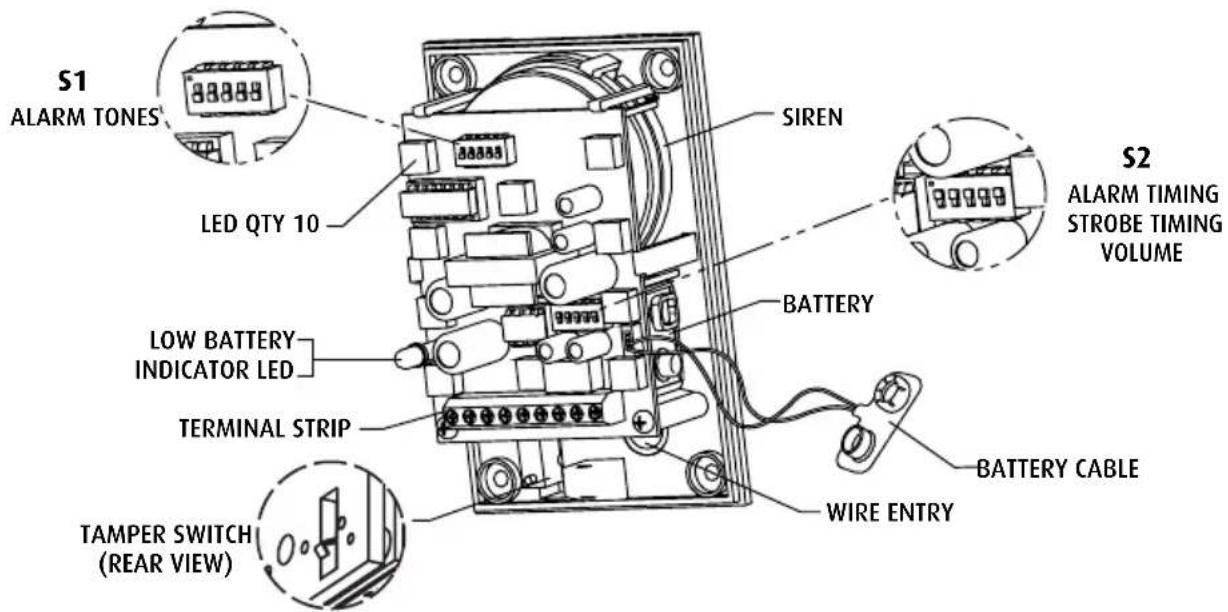
Step 2 - Alarm Tones - S1
| 1 2 3 4 5 | 1 2 3 4 5 |
| 1 0 0 0 0 0 BUZZ | 17 0 0 0 0 1 STANDARD ALARM |
| 2 1 0 0 0 0 SLOW ON/OFF | 18 1 0 0 0 1 #3 FAST |
| 3 0 1 0 0 0 SLOW SIREN | 19 0 1 0 0 1 #5 SLOW |
| 4 1 1 0 0 0 3 BEEP/PAUSE/REPEAT | 20 1 1 0 0 1 FAST BEEP |
| 5 0 0 1 0 0 UFO FAST | 21 0 0 1 0 1 SOUND A |
| 6 1 0 1 0 0 FAST SIREN | 22 1 0 1 0 1 SOUND B |
| 7 0 1 1 0 0 #5 FAST | 23 0 1 1 0 1 SOUND C |
| 8 1 1 1 0 0 #2 MEDIUM | 24 1 1 1 0 1 SOUND D |
| 9 0 0 0 1 0 #5 MEDIUM | 25 0 0 0 1 1 SOUND D LOUD |
| 10 1 0 0 1 0 SWOOP MEDIUM | 26 1 0 0 1 1 SOUND E |
| 11 0 1 0 1 0 #3 MEDIUM | 27 0 1 0 1 1 SOUND F |
| 12 1 1 0 1 0 BUZZ TONE | 28 1 1 0 1 1 SOUND G |
| 13 0 0 1 1 0 STEADY FAST | 29 0 0 1 1 1 SOUND H |
| 14 1 0 1 1 0 SWOOP SLOW | 30 1 0 1 1 1 #4 LOW |
| 15 0 1 1 1 0 CONTINUOUS | 31 0 1 1 1 1 SOUND K |
| 16 1 1 1 1 0 FAST REPEAT | 32 1 1 1 1 1 CONTINUOUS FAST |
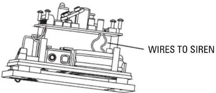
NOTE: Sound may be disabled by clipping wires to the siren. THIS WILL VOID ALL WARRANTIES. Remove two screws on circuit board; leave enough length of wire to possibly reattach in the future. Then insulate wires to prevent shorting to electronic components.
Step 3 - Alarm Timing and Volume - S2

bar_stacked
| Category | ALARM TIMING | STROBE TIMING | VOLUME | |---|---|---|---| | 1 ON | 1 | 2 | 3 | | 0 OFF | 0 | 1 | 1 || Alarm Timing | Siren 1 2 | Strobe 3 4 | Volume 5 | |||
| * | 15 seconds | 1 | 1 | 1 | 1 | |
| 30 seconds | 1 | 0 | 1 | 0 | ||
| 60 seconds | 0 | 1 | 0 | 1 | ||
| Continuous | 0 | 0 | 0 | 0 | ||
Step 4 - Terminal Strip Connections
"DC IN" are the only polarity sensitive terminals. When external power is used, battery will act as a backup. "Dry Contacts: NC, COM, NO" are used for remote alarm monitoring.
**Shipped with jumper wire 12-24 V installed. Remove to add key switch or other main power on/off switch.
If using power only to trigger alarm, add jumper to the alarm switch terminals. If not using key switch or other main power on/off, key switch must also have jumper.

Step 5 - Mounting Options
A) To STI Backbox SUB-71100A-W
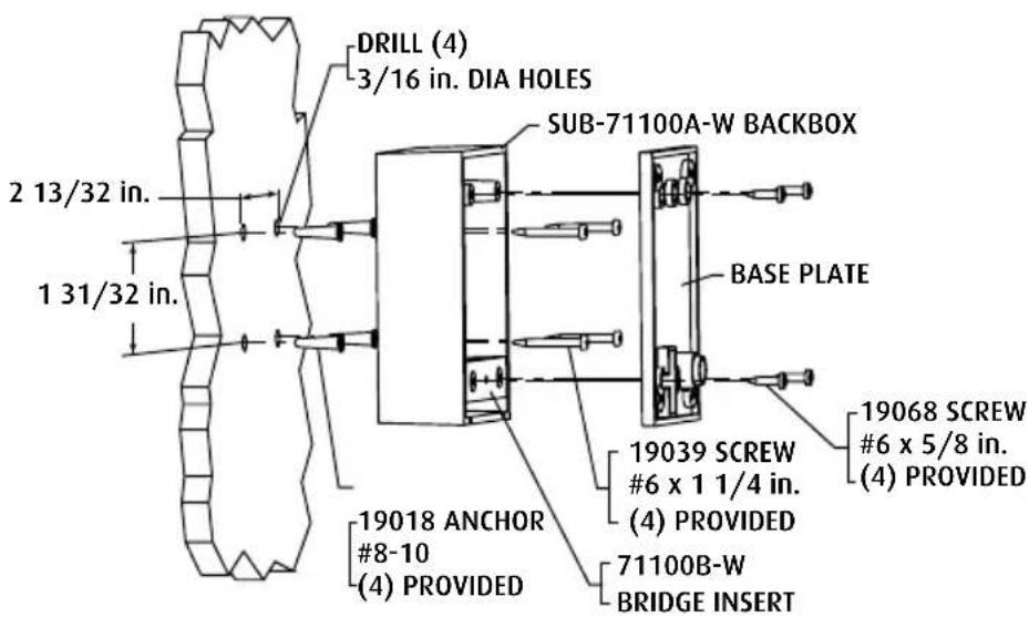
- Using 5/32 drill, drill through the (4) existing holes in back box (one in each corner).
- Place back box on wall and mark the mounting hole positions.
- If using #8-10 anchors, drill 3/16 dia. holes 1 in. deep into wall and press anchor into hole. If using #6 screws only, drill 3/32 dia. holes 1 ¼ in. deep.
- Mount back box to wall using #6 x 1 ¼ in. screws.
- Mount base plate as shown using (2) #6-32 x 1 in. screws.
Note: If not using STI back box, make sure surface will depress tamper switch.
B) To Key Mount Plate or into Wall without Electrical Box

C) To Single Gang Electrical Box
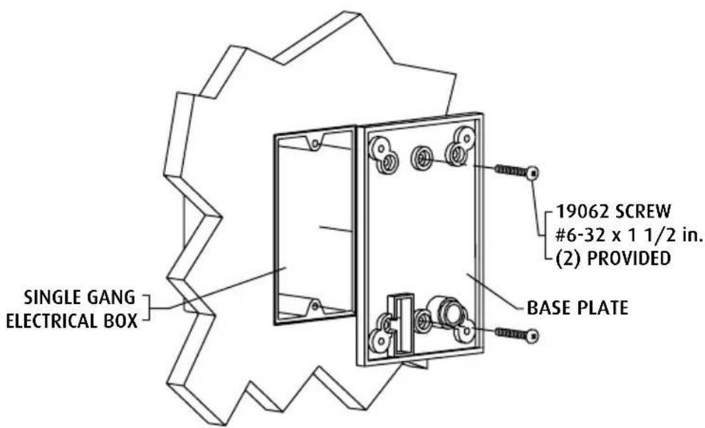
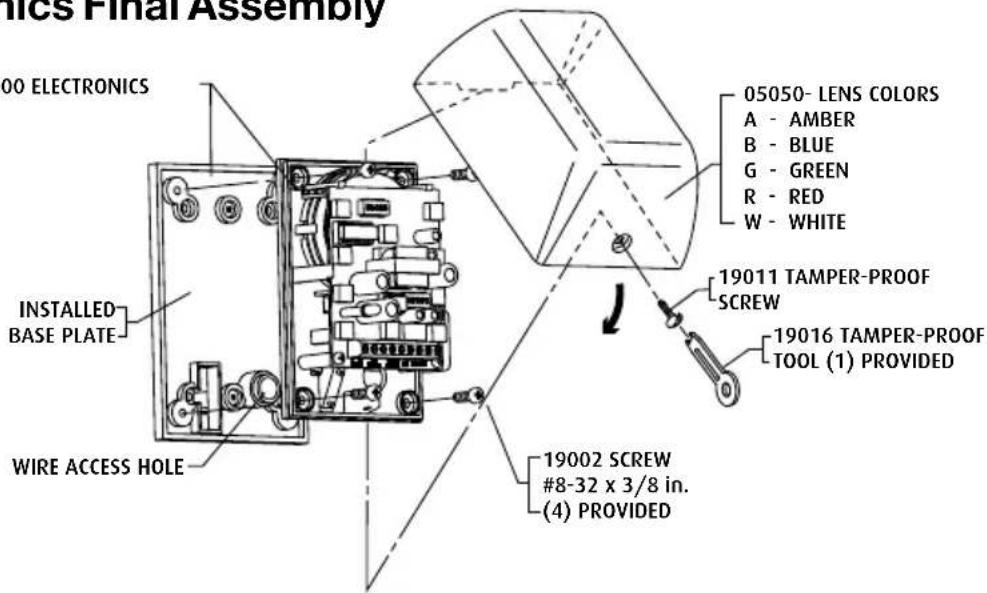
Step 6 - Electronics Final Assembly
Wiring: After mounting circuit board assembly, connect wires. Refer to terminal strip connections (step 4).
Lens installation: Slide lip of lens behind circuit board mounting plate. Rotate lens into position. Secure with tamperproof screw and special wrench.
Step 7 - Operation
• Turn key switch on to arm.
• Cycle key switch to reset alarm.
- Alarm will sound when cover is removed, unit is removed from the wall or cabinet is opened (alarm switch is electronically closed).
• To service, turn key switch off.

Safety Technology International, Inc.
2306 Airport Rd · Waterford, MI 48327, USA
Phone: 248-673-9898 • Fax: 248-673-1246
info@sti-usa.com • www.sti-usa.com
Safety Technology International (Europe) Ltd.
Unit 49G Pipers Road • Park Farm Industrial Estate
Redditch • Worcestershire • B98 0HU • England
Tel: 44 (0) 1527 520 999 • Fax: 44 (0) 1527 501 999
info@sti-europe.com • www.sti-europe.com

- Safety Technology International, Inc.
- Select-Alert Alarm Mini Controller
- Features
- CONTENTS
- SELECT-ALERT ASSEMBLY PARTS LIST
- ACCESSORIES
- WARNINGS
- WARRANTY INFORMATION
- DIMENSIONS
- INSTALLATION
- Step 1 - Electronic Setup
- Step 3 - Alarm Timing and Volume - S2
- Step 4 - Terminal Strip Connections
- Step 6 - Electronics Final Assembly
- Step 7 - Operation
- Safety Technology International (Europe) Ltd.
Brand : STI
Model : SA5000-B
Category : Alarm