
LA352 - Construction Equipment KUBOTA - Free user manual and instructions
Find the device manual for free LA352 KUBOTA in PDF.


User questions about LA352 KUBOTA
0 question about this device. Answer the ones you know or ask your own.
Ask a new question about this device
Download the instructions for your Construction Equipment in PDF format for free! Find your manual LA352 - KUBOTA and take your electronic device back in hand. On this page are published all the documents necessary for the use of your device. LA352 by KUBOTA.
USER MANUAL LA352 KUBOTA
natural_image
Line drawing of a tractor front loader with large tires and headrest (no text or symbols)


ABBREVIATION LIST
| Abbreviations | Definitions |
| 2WD | Two Wheel Drive |
| 4WD | Four Wheel Drive |
| API | American Petroleum Institute |
| ASAE | American Society of Agricultural Engineers, USA |
| ASTM | American Society for Testing and Materials, USA |
| DIN | Deutsches Institut für Normung, GERMANY |
| DT | Dual Traction [4WD] |
| fpm | Feet Per Minute |
| GST | Glide Shift Transmission |
| Hi-Lo | High Speed-Low Speed |
| HST | Hydrostatic Transmission |
| m/s | Meters Per Second |
| PTO | Power Take Off |
| RH/LH | Right-hand and left-hand sides are determined by facing in the direction of forward travel |
| ROPS | Roll-Over Protective Structure |
| min-1 (rpm) | Revolutions Per Minute |
| S-1 (r/s) | Revolutions Per Second |
| SAE | Society of Automotive Engineers, USA |
| SMV | Slow Moving Vehicle |
| UDT | KUBOTA UDT fluid (Transmission-hydraulic fluid) |


FOREWORD
You are now the proud owner of a KUBOTA Loader. This loader is a product of KUBOTA quality engineering and manufacturing. It is made of fine materials and under a rigid quality control system. It will give you long, satisfactory service. To obtain the best use of your loader, please read this manual carefully. It will help you become familiar with the operation of the loader and contains many helpful hints about loader maintenance. It is KUBOTA'S policy to utilize as quickly as possible every advance in our research. The immediate use of new techniques in the manufacture of products may cause some small parts of this manual to be outdated. KUBOTA distributors and dealers will have the most up-to date information. Please do not hesitate to consult with them.

SAFETY FIRST
This symbol, the industry's "Safety Alert Symbol", is used throughout this manual and on labels on the front loader itself to warn of the possibility of personal injury. Read these instructions carefully. It is essential that you read the instructions and safety regulations before you attempt to assemble or use this unit.

DANGER:
Indicates an imminently hazardous situation which, if not avoided, will result in death or serious injury.

WARNING :
Indicates a potentially hazardous situation which, if not avoided, could result in death or serious injury.

CAUTION:
Indicates a potentially hazardous situation which, if not avoided, may result in minor or moderate injury.
IMPORTANT :
Indicates that equipment or property damage could result if instructions are not followed.
NOTE :
Gives helpful information.
CONTENTS
▲SAFE OPERATION .... 1
SERVICING OF LOADER ....5
SPECIFICATIONS 6
SUITABLE TRACTOR....6
LOADER SPECIFICATIONS ...... 6
BUCKET SPECIFICATIONS......6
DIMENTIONAL SPECIFICATIONS......7
OPERATIONAL SPECIFICATIONS ..... 7
PERFORMANCE CHART......8
LOADER TERMINOLOGY 9
SETTING-UP INSTRUCTIONS .... 10
PRE-ASSEMBLY 10
TRACTOR PREPARATION .... 11
INSTALLATION INSTRUCTIONS......11
Operation Section
REMOVING AIR FROM HYDRAULIC SYSTEM....18
OPERATING THE LOADER....19
FILLING THE BUCKET 19
LIFTING THE LOAD....19
CARRYING THE LOAD....19
DUMPING THE BUCKET 20
LOWERING THE BUCKET 20
OPERATING WITH FLOAT CONTROL 20
LOADING FROM A BANK 21
PEELING AND SCRAPING....21
LOADING LOW TRUCKS OR SPREADERS FROM A PILE ....22
BACKFILLING 22
HANDLING LARGE HEAVY OBJECTS....23
Maintenance Section
MAINTENANCE 24
LUBRICATION 24
DAILY CHECKS 24
REMOVING THE LOADER....26
STORING THE LOADER 27
REINSTALLING THE LOADER ....28


SAFE OPERATION
Most loader equipment accidents can be avoided by following simple safety precautions. These safety precautions, if followed at all times, will help you operate your loader safely.
-
Read and understand both the tractor and the loader Operator's Manuals before using the loader. Lack of knowledge can lead to accidents.
-
For your safety, ROPS with a seat belt is strongly recommended by KUBOTA in almost all applications. If your tractor has a folding ROPS, fold it down only when absolutely necessary and fold it up and lock it again as soon as possible. Do not wear the seat belt when the folding ROPS is down or the fixed ROPS is removed. If you have any questions, consult your local KUBOTA Dealer. Always use seat belt when the tractor is equipped with a ROPS. Never use the seat belt when the tractor is not equipped with a ROPS.
-
Do not lift or carry anybody on the loader, bucket or attachment.
-
Never allow anyone to get under the loader bucket or reach through the boom when the bucket is raised.
-
Do not walk or work under a raised loader bucket or attachment unless it is securely blocked and held in position.
-
When operating on a slope, always operate up and down the slope, never across the slope.
-
Operate the loader from the tractor seat only.
-
For tractor stability and operator's safety, rear ballast must be added to the 3-point hitch and to the rear wheels.
-
To increase stability adjust the rear wheels to the widest setting that is suitable for your application.
-
Move and turn the tractor at low speeds.
-
Carry loader boom at a low position during transport. (You should be able to see over the bucket.)
-
Exercise extra caution when operating the loader with a raised bucket or attachment.
-
Avoid loose fill, rocks and holes. They can be dangerous for loader operation or movement.
-
Be extra careful when working on inclines.
-
Avoid overhead wires and obstacles when loader is raised. Contacting electric lines can cause electrocution.
-
Allow for the loader length when making turns.
-
Gradually stop the loader boom when lowering or lifting.
-
Use caution when handling loose or shiftable loads.
-
When loader work has been completed, lower loader boom to the ground, stop the engine, remove the key and lock the brakes before leaving the tractor seat.
-
Make sure the parked loader is on stands and on a hard, level surface.
-
Operate the loader controls only when properly seated at the controls.
-
Visually check for hydraulic leaks and broken, missing, or malfunctioning parts. Make necessary repairs before operation.
-
Escaping hydraulic oil under pressure can have sufficient force to penetrate the skin, causing serious personal injury. Do not use hands to search for suspected leaks. If injured by escaping fluid, obtain medical treatment at once.
-
Before disconnecting hydraulic lines, relieve all hydraulic pressure.
-
Do not tamper with the relief valve setting. The relief valve is pre-set at the factory. Changing the setting can cause overloading of the loader and tractor which may result in a serious personal injury.
-
Using loaders for handling large heavy objects, such as large round or rectangular bales, logs and oil drums is not recommended.
-
Handling large heavy objects can be extremely dangerous due to :
-
Danger of rolling the tractor over.
- Danger of upending the tractor.
-
Danger of the object rolling or sliding down the loader boom onto the operator.
-
If you must perform this sort of work (item 27), protect yourself by :
-
Never lifting the load higher than necessary to clear the ground.
- Adding rear ballast to the tractor to compensate for the load.
- Never lifting large object with equipment that may permit it to roll back onto the operator.
-
Moving slowly and carefully, avoiding rough terrain.
-
It is the loader owner's responsibility to be certain anyone operating the loader read this manual first to be aware of the safe way of operating the loader.
-
Always wear safety goggles when servicing or repairing the machine.
- When servicing or replacing pins in cylinder ends, bucket, etc., always use a brass drift and hammer. Failure to do so could result in injury from flying metal fragments.
- Replace damaged or illegible safety labels. See following page for required labels.
-
Do not modify, alter, or permit anyone else to modify or alter the loader, any of its components, or any loader function without first consulting a KUBOTA Dealer.
-
Assemble, remove and reinstall the loader only as directed in this manual. Failure to do this could result in serious personal injury or death.
- When operating another implement on a hillside, be sure to remove the loader to reduce the risk of roll over.
- Never lift or pull any load from any point of the loader with a chain, rope, or cable. Doing so could cause a roll over or serious damage to the loader.
- When a front loader is mounted on the tractor, enter and exit the operator's seat only from left side of the tractor.
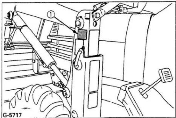
DANGER, WARNING AND CAUTION LABELS
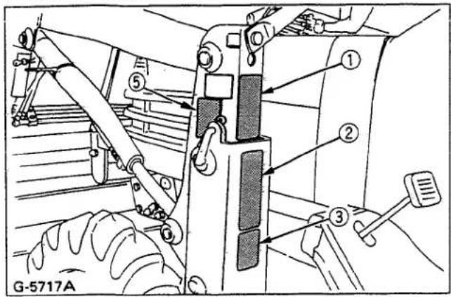

③ Part No. 75567-5642-2

①Part No. 75546-5643-1
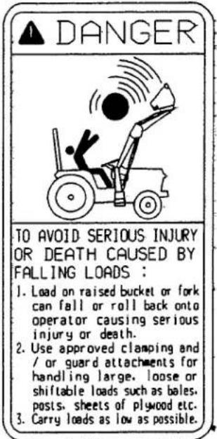
④Part No. 75546-5645-1

②Part No. 75546-5641-5

⑤ Part No. 75546-5644-1 (Both sides)

CARE OF DANGER, WARNING AND CAUTION LABELS
- Keep danger, warning and caution labels clean and free from obstructing material.
- Clean danger, warning and caution labels with soap and water, dry with a soft cloth.
- Replace damaged or missing danger, warning and caution labels with new labels from your local KUBOTA Dealer.
- If a component with danger, warning and caution label (s) affixed is replaced with new part, make sure new label (s) is (are) attached in the same location (s) as the replaced component.
- Mount new danger, warning and caution labels by applying on a clean dry surface and pressing any bubbles to outside edge.


SERVICING OF LOADER
This manual provides safety, set-up, operation, maintenance, removing, storing and reinstalling instructions for your new LA272, LA302, LA352 and LA402 loaders.
Your loader has been designed to give many years of satisfactory service. Successful operation and long life of the loader depends, of course, on proper operation and care. Please read this manual carefully and follow the instructions. Correct operation and maintenance will save much time and expense.
OBSERVE and FOLLOW all CAUTION instructions to help prevent personal injury and damage to the loader.
The reference to left hand and right hand used in this manual refers to the position when standing at the rear of the unit and facing forward.
If at any time, you have a service problem with your loader or need new parts, contact your local KUBOTA Dealer. Your dealer will need the loader model number and serial number to give you prompt, efficient service. The serial number is located on the outside of the side frame LH.
KUBOTA LOADER
Model LA402
Serial Number 14402
Date of Purchase 11/16/01
Name of Dealer Pauley Equipment
natural_image
Technical line drawing of a mechanical assembly with no visible text or symbols(1) Serial No.
SPECIFICATIONS
SUITABLE TRACTOR
B7400 model: LA272
B7500 model: LA272, LA302
B2410 model: LA352
B2710, B2910 HST models: LA402
LOADER SPECIFICATIONS
| Loader model | LA272 | LA302 | LA352 | LA402 | |
| Tractor model | B7400 | B7500 | B2410 | B2710, B2910 | |
| Wheel base (WB) mm(in.) | 1500 (59.1) | 1500 (59.1) | 1500 (59.1) | 1666 (65.6) | |
| Front tires | 6-12 | 6-12 | 7-12 | 7-12 | |
| Rear tires | 8.3-16 | 9.5-16 | 11.2-16 | 12.4-16 | |
| Boom cylinder | Bore mm(in.) | 38.1 (1-1/2) | 38.1 (1-1/2) | 44.5 (1-3/4) | 44.5 (1-3/4) |
| Stroke mm(in.) | 307 (12.1) | 307 (12.1) | 289 (11.4) | 435 (17.1) | |
| Bucket cylinder | Bore mm(in.) | 38.1 (1-1/2) | 38.1 (1-1/2) | 44.5 (1-3/4) | 44.5 (1-3/4) |
| Stroke mm(in.) | 330 (13.0) | 330 (13.0) | 330 (13.0) | 450 (17.7) | |
| Control Valve | 3 Position bucket control valve type | One Detent Float Position, Power Beyond Circuit | |||
| 4 Position bucket control valve type | One Detent Float Position, Two Stage Bucket Dump, Power Beyond Circuit | ||||
| Rated flow L/m(GPM) | 14.6 (3.9) | 16.6 (4.4) | 16.6 (4.4) | 24.4 (6.4) | |
| Maximum pressure kg/cm2(psi) | 141 (2000) | 155 (2200) | 141 (2000) | 141 (2000) | |
| Net weight (Approximate) kg(lbs.) | 208 (460) | 216 (475) | 226 (500) | 280 (617) | |
BUCKET SPECIFICATIONS
| Loader model | LA272, LA302 | LA352 | LA402 | LA402(Option) | |
| Model | Square 48 | Square 50 | Square 54 | Square 60 LM | |
| Width mm(in.) | 1220 (48.0) | 1270 (50.0) | 1370 (54.0) | 1525 (60.0) | |
| Depth (L) mm(in.) | 465 (18.4) | 495 (19.4) | 485 (19.1) | 525 (20.6) | |
| Height (M) mm(in.) | 480 (18.9) | 485 (19.1) | 525 (20.6) | 540 (21.2) | |
| Length (N) mm(in.) | 500 (19.6) | 525 (20.6) | 530 (20.8) | 570 (22.5) | |
| Capacity | Struck m^3 (cu.ft.) | 0.15 (5.2) | 0.16 (5.5) | 0.19 (6.7) | 0.23 (8.1) |
| Heaped m^3 (cu.ft.) | 0.17 (6.2) | 0.18 (6.5) | 0.23 (8.1) | 0.28 (9.9) | |
| Weight kg(lbs.) | 54 (120) | 62 (137) | 79 (175) | 82 (180) | |
DIMENSIONAL SPECIFICATIONS
| Loader model | LA272 | LA302 | LA352 | LA402 | ||
| (A) | Maximum lift height to pivot pin | mm(in.) | 1770 (69.7) | 1765 (69.5) | 1770 (69.7) | 2090 (82.3) |
| (B) | Maximum lift height under level bucket | mm(in.) | 1635 (64.4) | 1630 (64.2) | 1630 (64.2) | 1940 (76.4) |
| (C) | Clearance with bucket dumped | mm(in.) | 1310 (51.6) | 1320 (52.0) | 1310 (51.6) | 1665 (65.5) |
| (D) | Reach at maximum lift height | mm(in.) | 680 (26.8) | 645 (25.4) | 635 (25.0) | 660 (26.0) |
| (E) | Maximum dump angle | deg. | 45 | 45 | 45 | 40 |
| (F) | Reach with bucket on ground | mm(in.) | 1280 (50.4) | 1295 (51.0) | 1320 (52.0) | 1375 (54.1) |
| (G) | Bucket roll-back angle | deg. | 24 | 24 | 24 | 26 |
| (H) | Digging depth | mm(in.) | 80 (3.1) | 80 (3.1) | 80 (3.1) | 135 (5.3) |
| (J) | Overall height in carrying position | mm(in.) | 1150 (45.3) | 1160 (45.7) | 1160 (45.7) | 1195 (47.0) |
OPERATIONAL SPECIFICATIONS
| Loader model | LA272 | LA302 | LA352 | LA402 | ||
| Lift capacity to maximum height (Bucket bottom mid point) kg(lbs.) | 270 (595) | 300 (660) | 350 (770) | 400 (880) | ||
| (U) | Lift capacity to maximum height-at pivot pin kg(lbs.) | 310 (685) | 350 (770) | 420 (925) | 480 (1060) | |
| (V) | Lift capacity to maximum height kg(lbs.) | 225 (495) | 250 (550) | 305 (670) | 345 (760) | |
| (W) | Lift capacity to 1.5m (59in.) height-at pivot pin kg(lbs.) | 345 (760) | 390 (860) | 470 (1035) | 600 (1325) | |
| (X) | Lift capacity to 1.5m (59in.) height kg(lbs.) | 255 (560) | 290 (640) | 350 (770) | 455 (1005) | |
| (Y) | Breakout force-at pivot pin N(lbs.) | 6280 (1410) | 7010 (1575) | 8380 (1885) | 10250 (2305) | |
| (Z) | Breakout force N(lbs.) | 4460 (1005) | 4990 (1120) | 5940 (1335) | 7500 (1685) | |
| (VV) | Bucket rollback force at maximum height N(lbs.) | 5000 (1125) | 5540 (1245) | 8430 (1895) | 10450 (2350) | |
| (XX) | Bucket rollback force at 1.5m (59in.) lift height N(lbs.) | 5440 (1225) | 6030 (1355) | 9120 (2050) | 12540 (2820) | |
| (ZZ) | Bucket rollback force at ground line N(lbs.) | 4510 (1015) | 4950 (1115) | 7450 (1675) | 10540 (2370) | |
| Raising time sec. | 3.3 | 2.7 | 3.1 | 3.2 | ||
| Lowering time sec. | 2.5 | 2.2 | 2.5 | 2.4 | ||
| Bucket dumping time sec. | 1.9 | 1.6 | 1.9 | 1.9 | ||
| Bucket rollback time sec. | 2.2 | 1.8 | 2.5 | 2.4 | ||

PERFORMANCE CHART

LA272

line
| Lift Capacity (kg) | Height (mm) | | ------------------ | ----------- | | 0 | 1800 | | 500 | 600 | | 1000 | 200 |
LA302

line
| Lift Capacity (kg) | Height (mm) | | ------------------ | ----------- | | 0 | 1800 | | 500 | 800 | | 1000 | 400 | | 1500 | 0 |
LA352
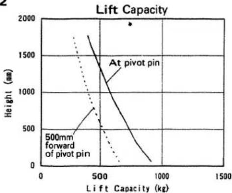
line
| Lift Capacity (kg) | Height (mm) - At pivot pin | Height (mm) - 500mm forward of pivot pin | | ------------------ | --------------------------- | ---------------------------------------- | | 0 | 1800 | 400 | | 500 | 1200 | 700 | | 1000 | 300 | 100 |
LA402
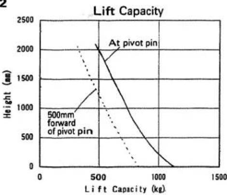
line
| Lift Capacity (kg) | Height (nm) | | ------------------ | ----------- | | 500 | 2000 | | 1000 | 0 |
line
| Rollback Force (KN) | Height (mm) | | ------------------- | ----------- | | 5 | 1700 |
line
| Rollback Force (KN) | Height (mm) | | ------------------- | ----------- | | 5 | 0 | | 6 | 200 | | 7 | 400 | | 8 | 600 | | 9 | 800 | | 10 | 1000 | | 11 | 1200 | | 12 | 1400 | | 13 | 1600 | | 14 | 1800 |
line
| Rollback Force (KN) | Height (mm) | | ------------------- | ----------- | | 7 | 0 | | 9 | 500 | | 10 | 1000 | | 11 | 1500 | | 12 | 1800 |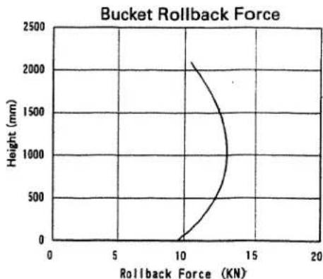
line
| Rollback Force (KN) | Height (mm) | | ------------------- | ----------- | | 10 | 0 | | 12 | 500 | | 14 | 1000 | | 16 | 1500 | | 18 | 2000 | | 20 | 2500 |LOADER TERMINOLOGY
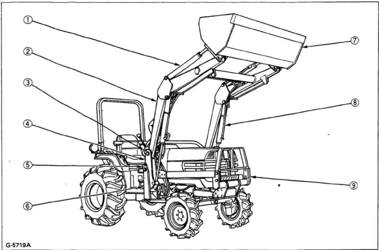
(1) Bucket cylinder
(7) Bucket
(2) Boom
(8) Boom cylinder
(3) Hydraulic control valve
(9) Brace
(4) Side frame
(5) Mounting pin
(6) Main frame
SETTING-UP INSTRUCTIONS
PRE-ASSEMBLY
Remove all loader components. Referring to the illustration, insure that all components have been included.

G-5720A
(1) Bucket (with 4 pins)
(2) Boom assembly
(3) Front guard (LA272 : option)
(4) Brace
(5) Side frame LH
(6) Side frame RH
(7) Main frame
(8) Side frame connector
(9) Hose 7, 1450 mm (57. 1 in.)
[LA272, LA302, LA352, without sleeve]
Hose 7, 1486 mm (58. 5 in.)
[LA402 with sleeve]
(10) Hose 5, 876 mm (34. 5 in.)
(11) Hose 6, 749 mm (29. 5 in.)
(12) Hydraulic block
(13) Control valve assembly
TRACTOR PREPARATION
- Remove the mid mount mower from the tractor if equipped.
- Locate the tractor on a firm level surface. Lower the implement to the ground, set the parking brake and stop the engine.
INSTALLATION INSTRUCTIONS
IMPORTANT:
- This loader has both standard and metric fasteners. Insure that the proper fasteners are placed in the correct locations. Metric fasteners that are marked 8.8 mount to the tractor. The bolts that go only in the loader are standard.
- Do not tighten any bolts firmly until most components are attached to the tractor.
- Before finally tightening all mounting hardware, start the engine and apply down pressure to the bucket until the loader raises the front wheels slightly, and make sure that the mounting pins can be rotated easily. Torque all bolts and nuts in this position.
- To avoid damage to hoses, adjust all connections to route hoses away from sharp edges.
Hydraulic Lines
- Remove the cover of the hydraulic block on the tractor.
- Install the loader hydraulic block to the tractor hydraulic block.
Tightening torque : 2.35 kgf-m (17 ft-lbs)
NOTE
- Reuse the bolts fastening the hydraulic block cover.

(1) Adapters
(A) Pump port
(2) Hydraulic block
(B) Power beyond port
- Remove the plug from the transmission case. Install the return fitting to the transmission case.
IMPORTANT
- Use teflon tape on the tapered thread of the return fitting.

natural_image
Technical line drawing of a vehicle engine bay with no visible text or symbols(1) Return fitting
- Connect Hose 7 to the return fitting as shown.

(1) Hose 7 (1450mm, 57.1in.)

(1) Hose 7 with sleeve (1486mm, 58.5in.)
Main Frame, Brace and Front Guard
- Remove the subframe brackets from the tractor. [LA402 only]

(1) Subframe bracket
- Turn the direction of the clamp for the drive shaft cover 90 degrees so that the clamp does not touch the loader main frame.

natural_image
Mechanical assembly diagram showing hoses and components (no text or symbols)(1) Clamp
- Attach the main frame to the tractor as shown.

(1) 4-M14 x 35 bolts
4-9/16 spring lock washers
(2) 6-M12 x 35 bolts (Pitch 1.75)
6-M12 spring lock washers

(1) 8-M14 x 35 bolts
8-9/16 spring lock washers
(2) 6-M12 x 35 bolts (Pitch 1.75)
6-M12 spring lock washers
6-1/2 hardened plain washers

(1) 4-M12 x 30 bolts (Pitch 1.25)
4-M12 spring lock washers
4-1/2 plain washers

(1) 4-M12 x 30 bolts (Pitch 1.25)
4-M12 spring lock washers
4-1/2 hardened plain washers
(2) 2-M14 x 35 bolts (Pitch 1.50)
2-9/16 spring lock washers
2-9/16 hardened plain washers
(3) Subframe
- Connect the main frame to the subframe on the tractor.【LA402 only】
NOTE
- Reuse the fasteners connecting the subframe brackets and the subframes.
-
Install all the flange bolts for the subframes from the inside.
-
Attach the brace to the tractor front frame as shown. (Do not tighten bolts firmly until all other related components have been installed.)

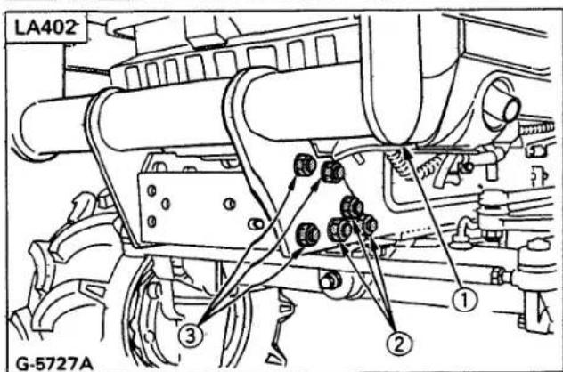
(1) Brace
(2) 6-9/16-18 UNF x 1 3/4 Bolts
6-9/16-18 UNF nuts
6-9/16 spring lock washers
(3) 6-9/16-18 UNF x 1 1/2 bolts
6-9/16-18 UNF nuts
6-9/16 spring lock washers
- Attach the rear ends of the brace to the main frame as shown.
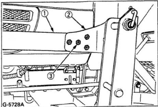
(1) Brace
(2) Main frame
(3) 8-9/16-18 UNF x 1 1/2 bolts
8-9/16-18 UNF nuts
8-9/16 spring lock washers
IMPORTANT
• Install all the bolts on each brace from the outside.
- Attach the front guard to the front loader brace.
NOTE
- The cushion on the front guard should be facing the tractor. [LA352, LA402]
• The front guard is an option for LA272.

(1) Front guard
(2) 4-1/2-20 UNF x 1 1/2 bolts
4-1/2-20 UNF nuts
4-1/2 spring lock washers
Hydraulic Valve and Hoses
- Connect Hose 5 (876 mm, 34.5 in.) to the power beyond port of the hydraulic block.
- Connect Hose 6 (749 mm, 29.5 in.) to the pump port of the hydraulic block.

(1) Hydraulic block
(A) Power beyond port
(2) Hose 5
(B) Pump port
(3) Hose 6
- Attach the valve assembly to the main frame as shown.

(1) Main frame
(2) Valve assembly
(3) 3-1/2-13 UNC x 1 1/4 bolts
3-1/2 - 13 UNC nuts
3-1/2 spring lock washers
- Connect Hose 5 (876 mm, 34.5 in.) to the power beyond port of the hydraulic control valve.
- Connect Hose 6 (749 mm, 29.5 in.) to the pump port of the hydraulic control valve.
- [LA272, LA302, LA352] Route Hose 7 (1450mm, 57.1in.) from the return fitting as shown and connect it to the tank port of the hydraulic control valve. Route Hose 7 above the mower linkage, and clear of all moving parts. Clamp Hose 7 with two plastic ties as shown.
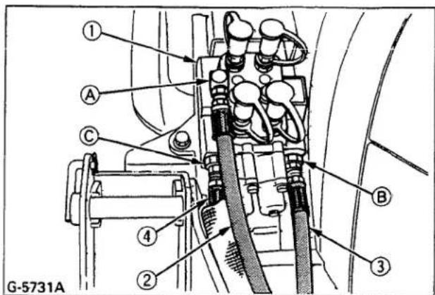
(1) Hydraulic control valve
(2) Hose 5
(3) Hose 6
(4) Hose 7
(A) Power beyond port
(B) Pump port
(C) Tank port

(1) Hose 7
(2) Plastic tie
(3) Mower linkage

(1) Hose 7
(2) Plastic tie
【LA402】
Route Hose 7 (1486 mm, 58.5 in.) with the nylon sleeve from the return fitting as shown and connect it to the tank port of the hydraulic control valve. Route Hose 7 on the hose support plate and clear of all moving parts as shown.

(1) Hose 7
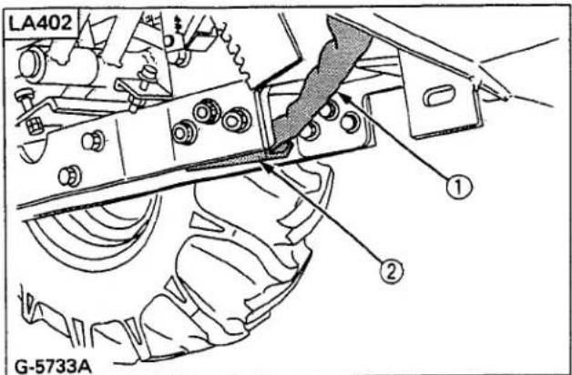
(1) Hose 7
(2) Hose support plate
- Clamp three hoses with plastic tie as shown.

(1) Plastic tie
Side Frames, Boom Assembly and Bucket
- Set the side frame LH and RH onto the main frame. Install the mounting pins and secure them with the spring pins.
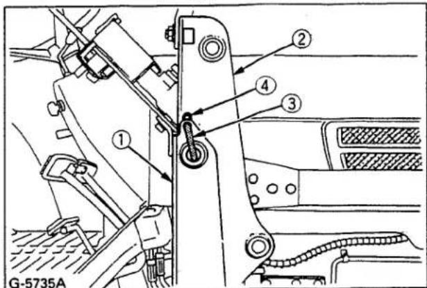
(1) Main frame
(3) Mounting pin
(2) Side frame
(4) Spring pin
- Attach the boom assembly to the side frames as shown.

(1)【LA272, LA302】
4 - Pin 4
4 - 3/16 x 1 3/4 cotter pins
【LA352, LA402】
4 - Pin 2
4-1/4-20 UNC x 2-1/4 bolts
4-1/4-20 UNC locking nuts
3. Attach the bucket to the boom.

natural_image
Technical line drawing of a mechanical assembly with labeled components (no readable text or symbols)(1) [LA272, LA302]
4 - Pin 4
4 - 3/16 x 1 3/4 cotter pins
(1) [LA352, LA402]
4 - Pin 3
4-1/4-20 UNC × 2-1/4 bolts
4-1/4-20 UNC locking nuts
Side Frame Connector
Attach the side frame connector to the top of the side frame as shown.

(1) Side frame connector
(2) 2-9/16-18 UNF×1 1/4 bolts
2-9/16-18 UNF nuts
2-9/16 spring lock washers
Hydraulic Hoses
Connect four hoses with quick couplers to the nipples on the control valve as indicated with color marks.

(1) Control valve
■ Tightening Bolts and Nuts
Tighten all bolts and nuts in the following order to the required torque.
NOTE:
- Before finally tightening all mounting hardware, start the engine and apply down pressure to the bucket until the loader raises the front wheels slightly, and make sure that the mounting pins can be rotated easily. Tighten all bolts and nuts in this position.
| Sequence | Location | Bolt / Nut | Required Torque kgf·m (ft·lbs) | ||
| LA272LA302LA352 | LA402 | LA272LA302LA352 | LA402 | ||
| 1 | Main frame(Clutch housing) | 6-M12 Bolts | 8.5 (61) | ||
| 2 | Main frame(Front axle frame) | 4-M14Bolts | 8-M14Bolts | 15.0 (108) | |
| 3 | Main frame(Center frame) | 4-M12 Bolts | 10.0 (72) | ||
| 4 | - | 2-M14Bolts | - | 17.0 (123) | |
| 5 | Main frame(Sub frame) | - | 6-M12Nuts | - | 8.5 (61) |
| 6 | Brace | 14-9/16Nuts | 20-9/16Nuts | 18.0 (130) | |
| 7 | Side frame connector | 2 - 9/16 Nuts | 15.0 (108) | ||
PRE-OPERATION CHECK
LUBRICATION
Lubricate all grease fittings with SAE multipurpose grease.
natural_image
Technical line drawing of a mechanical lifting device (no text or symbols)TRANSMISSION FLUID
Check tractor transmission fluid level. Add fluid if necessary. Refer to the tractor's Operator's Manual for instructions and proper fluid. Repeat this check after purging air from the system. At that time, it will be necessary to add transmission fluid.
REAR BALLAST

CAUTION
To avoid personal injury:
- For tractor stability and operator's safety, rear ballast should be added to the rear of the tractor in the form of 3-point counter weight and rear wheel ballast. The amount of rear ballast will depend on the application.
| Implement as Counter Weight | |
| 4' Land Scraper | Approx. 225 kg (495 lbs.) |
| Rear Blade | |
| Rotary Tiller | Approx. 200 kg (440 lbs.) |
| Backhoe | |
Liquid Ballast in Rear Tires
Water and calcium chloride solution provides a safe and economical ballast. Used properly, it will not damage tires, tubes or rims. The addition of calcium chloride is recommended to prevent the water from freezing. This method of weighting the wheels is fully approved by the tire manufacturers. See your tire dealer for this service.
Liquid weight per tire (75 Percent filled)
| Tire sizes | 8.3-16 | 9.5-16 | 11.2-16 | 12.4-16 |
| Slush free at -10°C (14°F) Solid at -30°C (-22°F) [Approx. 1 kg (2 lbs.) CaCl2 per 4 L (1 gal) of water] | 35 kg (77 lbs.) | 54 kg (119 lbs.) | 70 kg (155 lbs.) | 85 kg (187 lbs.) |
| Slush free at -24°C (-11°F) Solid at -47°C (-52°F) [Approx. 1.5 kg (3.5 lbs.) CaCl2 per 4 L (1 gal) of water] | 37 kg (82 lbs.) | 57 kg (126 lbs.) | 74 kg (163 lbs.) | 89 kg (196 lbs.) |
| Slush free at -47°C (-52°F) Solid at -52°C (-62°F) [Approx. 2.25 kg (5 lbs.) CaCl2 per 4 L (1 gal) of water] | 39 kg (86 lbs.) | 60 kg (132 lbs.) | 78 kg (172 lbs.) | 94 kg (207 lbs.) |
IMPORTANT:
- Do not fill tires with water or solution more than 75% of capacity (to the level of valve stem at 12 o'clock position).

(1) Air
(A) Correct: 75% Full
Air compresses like a cushion
(2) Water
(B) Incorrect: 100% Full
Water cannot be compressed
NOTE:
- When mounting a heavy rear implement, liquid in the tire may not be required.
IMPORTANT:
- Do not add liquid ballast or any other weights to the front tires.
TIRE INFLATION
Insure that the tractor tires are properly inflated.
Refer to the tractor's Operator's Manual for optional tires.
Inflation pressure
| Tire Sizes | Inflation Pressure | |
| Rear | 8.3-16, 4PR | 140kPa (1.4kgf/cm2, 20psi) |
| 9.5-16, 4PR | 140kPa (1.4kgf/cm2, 20psi) | |
| 11.2-16, 4PR | 130kPa (1.3kgf/cm2, 18psi) | |
| 12.4-16, 4PR | 120kPa (1.2kgf/cm2, 17psi) | |
| Front | 5.00-10, 4PR | 270kPa (2.8kgf/cm2, 40psi) |
| 6-12, 4PR | 200kPa (2.0kgf/cm2, 28psi) | |
| 6.50-10, 4PR | 200kPa (2.0kgf/cm2, 28psi) | |
| 7-12, 4PR | 170kPa (1.7kgf/cm2, 24psi) |
TEST OPERATION

CAUTION
To avoid personal injury:
- Keep engine speed at low idle during the test operation.
- Escaping hydraulic fluid under pressure can have sufficient force to penetrate skin, causing serious personal injury.
Before disconnecting lines, be sure to relieve all pressure.
Before applying pressure to system, be sure all connections are tight and that lines, tubes and hoses are not damaged. Fluid escaping from a very small hole can be almost invisible. Use a piece of cardboard or wood, rather than hands to search for suspected leaks.
If injured by escaping fluid, see a doctor at once. Serious infection or allergic reaction will develop if proper medical treatment is not administered immediately.

flowchart
graph TD
    A["FLOAT"] --> B["DOWN"]
    B --> C["N"]
    C --> D["UP"]
    C --> E["DUMP"]
    C --> F["DOWN & ROLL BACK"]
    C --> G["DOWN & DUMP"]
    C --> H["ROLL BACK"]
    C --> I["UP & DUMP"]
NOTE:
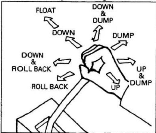
- When the lever is at each corner position marked by asterisk (*), boom and bucket cylinders work at the same time. However, the position marked by cross is not recommended for scooping because of insufficient lift force.
To begin test operation, slightly move the control lever from the "N" position. Slowly raise the loader boom just enough for the bucket to clear the ground when fully dumped. Slowly work through the dump and roll back cycles.
IMPORTANT:
- If the boom or bucket does not work in the directions indicated on the label, lower the bucket to the ground, stop the engine, and relieve all hydraulic pressure. Recheck and correct all hydraulic connections.
4 Position bucket control valve type
This control valve has a two-stage dump position. The first dump position (by moving the lever to the right) is the "Regular" dump position.
It has good power and control for precise dumping. This position should be used when operating another implement with the loader's control valve.
The second dump position (to further right) features greater speed for dumping. Theses two positions are separated by a "Feel" position for your convenience.
REMOVING AIR FROM HYDRAULIC SYSTEM
Repeat raising and lowering the boom and bucket operations until all the air is removed from the system and the system responds properly.
IMPORTANT:
- Do not move the control lever into float position when the bucket is off the ground.
The loader should be operated with the tractor engine speed depending on the application and the operator's level of experience. Excessive speeds are dangerous, and may cause bucket spillage and unnecessary strain on the tractor and loader.
When operating in temperatures below -1^(30^) , run the tractor engine below 1200min^-1(rpm) until the oil temperature exceeds -1^(30^) .
The following text and illustrations offer suggested loader and tractor operating techniques.
IMPORTANT:
- When operating the loader in rough terrain, remove the mower to avoid damage to the mower.
FILLING THE BUCKET
Approach and enter the pile with a level bucket.

natural_image
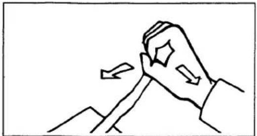
Simple line drawing of a ramp with a triangular load, no text or symbols presentEase control lever toward you and then back to rollback and lift the bucket.
natural_image
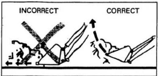
Line drawing of a hand gripping a piece of paper or paper, with arrows indicating movement (no text or symbols)The rollback and lifting of the bucket will increase efficiency because a level bucket throughout the lifting cycle resists bucket lift and increases breakaway effort.
NOTE:
- Do not be concerned if the bucket is not completely filled during each pass. Maximum productivity is determined by the amount of material loaded in a given period of time. Time is lost if two or more attempts are made to fill the bucket on each pass.
LIFTING THE LOAD
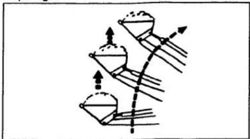
When lifting the load, keep the bucket positioned to avoid spillage.
natural_image
Diagram of a mechanical or architectural structure with three conical components and directional arrows (no text or labels)
WARNING
To avoid serious personal injury:
- Do not attempt to lift bucket loads in excess of the loader capacity.
- Before raising the bucket to full height, make sure the tractor is on level ground. If not, it may tip over, even if the tractor is not moving.
CARRYING THE LOAD
Position the bucket just below the level of the tractor hood for maximum stability and visibility, whether the bucket is loaded or empty.

natural_image
Simple line drawing of a tractor with a crew member, no text or symbols presentUse extreme care when operating the loader on a slope. Keep the bucket as low as possible. This keeps the bucket and tractor center of gravity low and will provide maximum tractor stability.

WARNING
To avoid serious personal injury:
- Be extra careful when working on inclines.
- When operating on a slope, always operate up and down the slope, never across the slope.

When transporting a load, keep the bucket as low as possible to avoid tipping, in case a wheel drops in a rut.
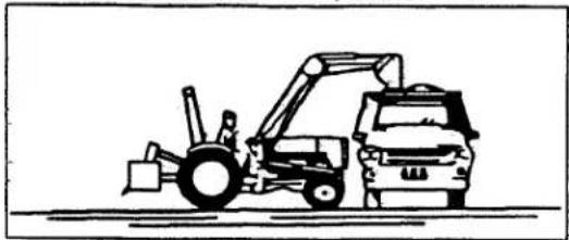
DUMPING THE BUCKET
Lift the bucket just high enough to clear the side of the vehicle. Move the tractor in as close to the side of the vehicle as possible, then dump the bucket.
natural_image
Line drawing of a construction vehicle with front loader and cab (no text or symbols)LOWERING THE BUCKET
After the bucket is dumped, back away from the vehicle while lowering and rolling back the bucket.
flowchart
graph TD
    A["FLOAT"] --> B["DOWN"]
    B --> C["DOWN & DUMP"]
    C --> D["DUMP"]
    D --> E["UP & DUMP"]
    E --> F["UP"]
    F --> G["ROLL BACK"]
    G --> H["ROLL BACK"]
    H --> I["DOWN & ROLL BACK"]
OPERATING WITH FLOAT CONTROL
During operation on hard surface, keep the bucket level and put the lift control in the float position to permit the bucket to float on the working surface.
If hydraulic down pressure is exerted on the bucket it will wear faster than normal.

The float position will also avoid mixing of surface material with stockpile material. The float position will reduce the chance of surface gouging while removing snow or other material, or when working with a blade.

LOADING FROM A BANK
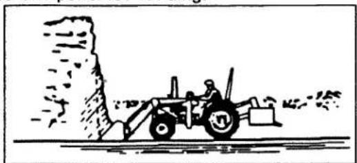
Choose a forward gear that provides a safe ground speed and power for loading.
natural_image
Illustration of a tractor with a bucket truck operating near a large pile of material (no text or symbols)
WARNING
To avoid the possibility of serious personal injury:
• Exercise caution when undercutting high banks.
- Dirt slides can be dangerous. Load from as low as possible for maximum efficiency.
NOTE:
- Loader lift and break-away capacity diminish as loading height is increased.

natural_image
Diagram showing mechanical components and a pile of material, no text or symbols presentSide cutting is a good technique for cutting down a big pile. Wheel width should not exceed the bucket width for this procedure.

natural_image
Simple line drawing of a bulldozer operating near a large pile of hay (no text or symbols)If the pile sides are too high and liable to cause cave-in, use the loader to break down the sides until a slot can be cut over the top.

natural_image
Simple line drawing of a tractor pulling a heavy truck through a mountainous terrain (no text or symbols)Another method for large dirt piles is to build a ramp to approach to the pile.

natural_image
Simple line drawing of a slope with a triangular support structure and a rocky outcrop (no text or symbols)It is important to keep the bucket level when approaching a bank or pile. This will help avoid gouging the work area.
PEELING AND SCRAPING
natural_image
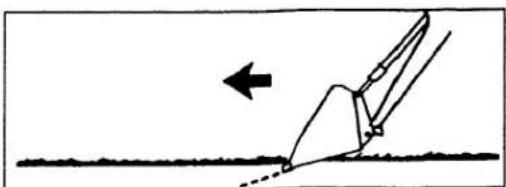
Simple line drawing of a mechanical component with an arrow indicating direction (no text or symbols)Use a slight bucket down angle, travel forward, and hold the lift control forward to start the cut. Make a short cut and break-out cleanly.
natural_image
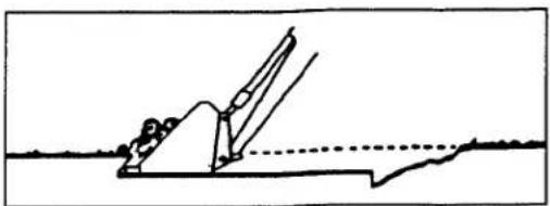
Simple line drawing of a person using a tool on a surface, with no text or symbols present.With the bucket level, start a cut at the notch approximately 2 in. deep. Hold the depth by feathering the bucket control to adjust the cutting edge up or down. When the front tires enter the notch, adjust the boom cylinder to maintain proper depth.

natural_image
Diagram of a curved channel with hatched fill and dashed line indicating a reference or boundary (no text or symbols)Make additional passes until the desired depth is reached. During each pass, use only the bucket control while at working depth. This will allow you to concentrate on controlling the bucket angle to maintain a precise cut.
LOADING LOW TRUCKS OR SPREADERS FROM A PILE

natural_image
Illustration of two tractors with a pile of dust above them (no text or symbols)For faster loading, minimize the angle of turn and length of run between pile and spreader.
natural_image
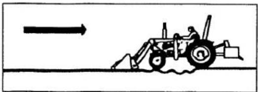
Simple line drawing of a tractor pulling a vehicle with an arrow indicating direction (no text or symbols)Backgrade occasionally with a loaded bucket to keep the work surface free of nuts and holes. Also, hold the lift control forward so the full weight of the bucket is scraping the ground. Use the heel of the bucket.
BACKFILLING

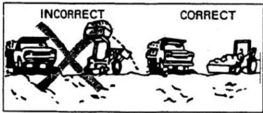
Approach the pile with the bucket flat.

Poor operating methods will move less dirt and make it more difficult to hold a level grade.
IMPORTANT:
- Do not use the bucket in the dumped position for bulldozing. As shown above, this method will impose severe shock loads on the dump-linkage, the bucket cylinders, and the tractor.
natural_image
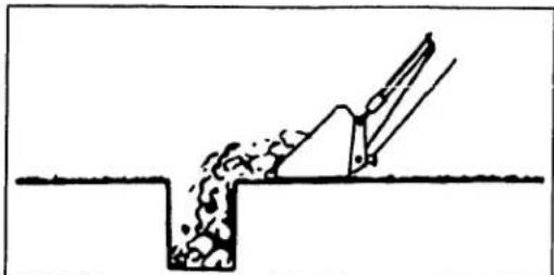
Simple line drawing of a mechanical device interacting with a granular material inside a V-shaped groove (no text or symbols)Leave dirt in the bucket because dumping on each pass wastes time.

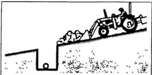
Operate at right angles to the ditch. Taking as big a bite as the tractor can handle.

Leave dirt which drifts over the side of the bucket for final cleanup.
natural_image
Illustration of a tractor pulling a slope with debris on the ground (no text or symbols)Pile dirt on the high side for easier backfilling on a slope.
HANDLING LARGE HEAVY OBJECTS

WARNING
To avoid serious personal injury:
● Handling large, heavy objects can be dangerous due to :
(A)Danger of rolling the tractor over.
(B) Danger of upending the tractor.
(C)Danger of the object rolling or sliding down the loader boom onto the operator.
- If you must perform the above work, protect yourself by:
(A) Not lifting the load higher than necessary to clear the ground when moving.
(B) Adding rear ballast to the tractor to compensate for the load.
(C) Not lifting large objects with equipment that does not have an anti-rollback device.
(D) Moving slowly and carefully.
(E) Avoiding rough terrain.
(F) Keeping transport distance as short as possible.
MAINTENANCE
LUBRICATION

CAUTION
To avoid personal injury:
- Be sure to check and service the tractor on a flat place with the bucket on the ground, engine shut off, the key removed and the parking brake on.
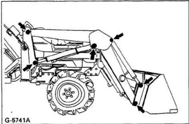
- Lubricate all 12 grease fittings every 10 hours of operation. Also, lubricate joints of control lever linkage every 10 hours. High quality grease designating "extreme pressure" and containing Molybdenum disulfide is recommended. This grease may specify "Moly EP" on its label.

natural_image
Technical line drawing of a mechanical trawhe with no visible text or symbols- Daily before operation, check the tractor hydraulic fluid level. If low, add as described in the tractor's Operator's Manual. Also change the filter element and the hydraulic fluid as recommended in the tractor's Operator's Manual.
DAILY CHECKS
-
Check all hardware daily before operation. Tighten hardware to torque values as specified in the "Installation Instructions" and "Tightening Torque Chart".
-
With the engine off and the bucket on the ground, inspect all hoses for cuts or wear. Check for signs of leaks and make sure all fittings are tight.

CAUTION
To avoid personal injury:
- Escaping hydraulic fluid under pressure can have sufficient force to penetrate skin, causing serious personal injury. Before disconnecting lines, be sure to relieve all pressure. Before applying pressure to system, be sure all connections are tight and that lines, tubes, and hoses are not damaged. Fluid escaping from a very small hole can be almost invisible. Use a piece of cardboard or wood, rather than hands, to search for suspected leaks.

(1) Hydraulic line
(2) Cardboard
(3) Magnifying glass
If injured by escaping fluid, see a doctor at once. Serious infection or allergic reaction will develop if proper medical treatment is not administered immediately.
- When removing the engine side covers, be careful not to touch hot loader cylinders.
Allow all surfaces to cool before performing maintenance.
General torque specification
| American standard cap screwswith UNC or UNF threads | Metric cap screws | |||
| SAE grade No. | GR 5 or GR 8 | property class | 8.8Approx. SAE GR 5 | |
| (N-m)(kgf-m)(ft-lbs) | 9.8 to 11.71.0 to 1.27.2 to 8.6 | (M6)(N-m)(kgf-m)(ft-lbs) | 9.8 to 11.21.0 to 1.17.2 to 8.3 | |
| (N-m)(kgf-m)(ft-lbs) | 19 to 23.11.9 to 2.414 to 17 | (M8)(N-m)(kgf-m)(ft-lbs) | 23.6 to 27.42.4 to 2.817.4 to 20.2 | |
| (N-m)(kgf-m)(ft-lbs) | 33.9 to 40.73.5 to 4.225 to 30 | (M10)(N-m)(kgf-m)(ft-lbs) | 48.1 to 55.84.9 to 5.735.5 to 41.2 | |
| (N-m)(kgf-m)(ft-lbs) | 88.1 to 105.89.0 to 10.865 to 78 | (M12)(N-m)(kgf-m)(ft-lbs) | 77.5 to 90.17.9 to 9.257.2 to 66.5 | |
| (N-m)(kgf-m)(ft-lbs) | 122 to 146.412.4 to 14.990 to 108 | (M14)(N-m)(kgf-m)(ft-lbs) | 124 to 14712.6 to 15.091.2 to 108 | |
| (N-m)(kgf-m)(ft-lbs) | 176.3 to 211.518.0 to 21.6130 to 156 | (M16)(N-m)(kgf-m)(ft-lbs) | 196 to 22520.0 to 23.0145 to 166 | |


REMOVING THE LOADER

CAUTION
To avoid personal injury:
- For removing the loader, choose flat and hard ground, preferably concrete. When starting the engine or using the hydraulic control valve, always sit in the operator's seat.
If the ground surface is soft, place suitable planks on the ground for the bucket and stands. Make sure bucket and stands are at ground level.
- Raise the boom until the stands can be rotated.
- Stop the engine.
- Remove the spring pins holding the stands to the boom.
- Slide the stands outward and rotate them until the hole in the stand and pin on the boom are aligned. Then slide the stands inward and insert the spring pin as shown.
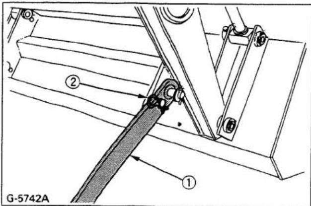
(1) Stand
(2) Spring pin
- Start the engine.
- Dump the bucket approximately 20 degrees.
- Lower the boom and raise the front wheels slightly.
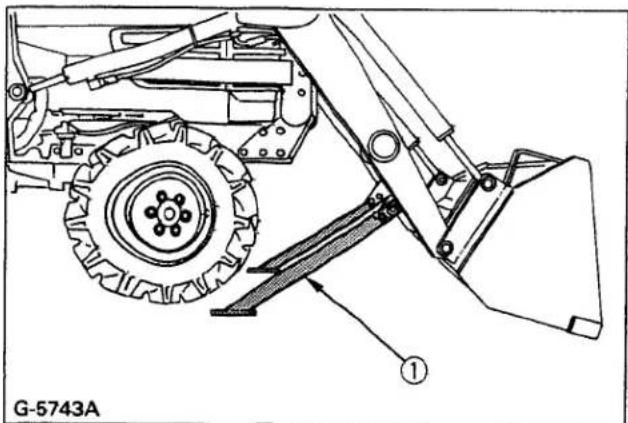
natural_image
Technical line drawing of a mechanical assembly with labeled parts (G-5743A), showing no readable text or symbols beyond the label.(1) Stand
IMPORTANT:
- Lift the front wheels with the bucket. Do not attempt to lift them with the stands.
- Stop the engine.
- Remove the mounting pins from the loader main frame and hold them on the side frames with spring pins.
- Start the engine and run at idle. Slowly move the hydraulic control lever to rollback position to raise the loader side frames up and out of the receivers of the main frames as shown.

(1) Hydraulic control lever
- Stop the engine.
- Slowly release all hydraulic pressure by moving the hydraulic control lever in all directions.
- Disconnect the four hoses with quick couplers at the control valve and place them on the right side of the boom.
- Place the protective caps and plugs on the quick coupler ends.
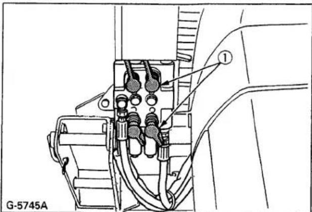
(1) Protective caps
- Start the engine and slowly back the tractor away from the loader.
STORING THE LOADER
- Store the loader in a clean dry place.
- Make sure the loader is properly supported.
- Attach the protective plugs and caps to the couplers to protect from dust.

natural_image
Technical line drawing of a mechanical lifting device (no text or symbols)- Check hydraulic hoses and connections. Repair or replace if necessary.
- Repair or replace any worn, damaged or missing parts.
- Lubricate loader as described "LUBRICATION" in Maintenance section.
- Apply a coat of grease to all exposed cylinder rods and mounting pins to prevent rust.
- Repaint worn or scratched parts.
REINSTALLING THE LOADER

CAUTION
To avoid personal injury:
- When starting the engine and operating the control valve, always sit in the operator's seat.
- Slowly drive the tractor between the loader side frames until the rear portion of the side frames touches the main frame.
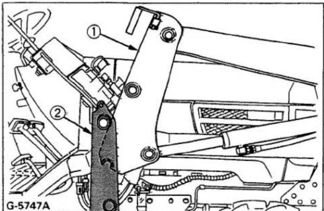
(1) Side frame
(2) Main frame
- Stop the engine.
- Connect four hoses with couplers to the nipples on the control valve as indicated with color marks. Then connect protective caps and plugs together.
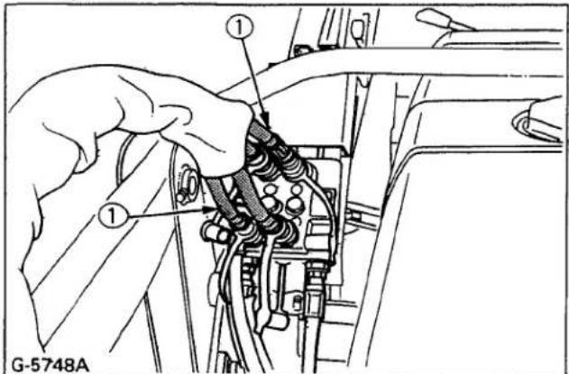
(1) Hose 1 and Hose 2
- Start the engine and run at idle.
- Slowly move the hydraulic control lever to dump position to lower the side frames into the main frame and engage the bosses of the side frames to the guide plates of the main frame. Then lift the front wheels slightly with the loader.

natural_image
Technical line drawing of a mechanical harvester (no text or symbols present)(1) Hydraulic control lever
IMPORTANT:
- Do not attempt to lift the front wheels with the stands.
- Stop the engine. Reinstall the mounting pins and secure them with the spring pins.
- Start the engine.
- Raise the boom until the stands can be rotated.
- Stop the engine.
- Store the stands to their original positions and secure them with the spring pins as shown.

(1) Stand
(2) Spring pin
- Start the engine.
- Lower the boom and level the bucket.
KUBOTA Corporation is···
Since its inception in 1890, KUBOTA Corporation has grown to rank as one of the major firms in Japan.
To achieve this status, the company has through the years diversified the range of its products and services to a remarkable extent. Nineteen plants and 16,000 employees produce over 1,000 different items, large and small.
All these products and all the services which accompany them, however, are unified by one central commitment.
KUBOTA makes products which, taken on a national scale, are basic necessities. Products which are indispensable. Products which are intended to help individuals and nations fulfill the potential inherent in their environment. KUBOTA is the Basic Necessities Giant.
This potential includes water supply, food from the soil and from the sea, industrial development, architecture and construction, and transportation.
Thousands of people depend on KUBOTA's know-how, technology, experience and customer service. You too can depend on KUBOTA.
Kubota
U.S.A. : KUBOTA TRACTOR CORPORATION
3401 Del Amo Blvd., Torrance, CA 90503, U.S.A. Telephone : (310)370-3370
Western Division : 6665 E. Hardaway Rd., Stockton, CA 95215
Telephone : (209)931-5051
Central Division : 14855 FAA Blvd., Fort Worth, TX 76155
Telephone : (817)571-0900
Northern Division : 2626 Port Road, Columbus, OH 43217
Telephone : (614)492-1100
Southeast Division : 1025 Northbrook Parkway, Suwanee, GA 30024 Telephone : (770)995-8855
Canada : KUBOTA CANADA LTD.
5900 14th Avenue, Markham, Ontario, L3S 4K4, Canada
Telephone : (905)294-7477
Delta Distribution Center : 7979 82nd St, Delta B.C. V4G 1L7
Telephone : (604)940-6061
Drummondville Distribution Center : 5705 Place Kubota, Drummondville, Québec, J2B 6R4
Telephone : (819)478-7151
France : KÜBOTA EUROPE S.A.
19-25, Rue Jules Vercruysse, Z.I. BP88, 95101 Argenteuil Cedex, France
Telephone : (33)1-3426-3434
Germany : KUBOTA (DEUTSCHLAND) GmbH
Senefelder Str. 3-5 63110 Rodgau /Nieder-Roden, Germany
Telephone : (49)6106-873-0
U.K. : KUBOTA (U.K.) LTD.
Dormer Road, Thame, Oxfordshire, OX9 3UN, U.K.
Telephone : (44)1844-214500
Australia : KUBOTA TRACTOR AUSTRALIA PTY LTD.
100 Keilor Park Drive, Tullamarine, Victoria 3043 Australia
155 Panay Avenue, South Triangle Homes, 1103 Quezon City, Philippines
Telephone : (63)2-9201071
Taiwan : SHIN TAIWAN AGRICULTURAL MACHINERY CO., LTD.
16, Fengping 2nd Rd, Taliao Shiang Kaohsiung 83107, Taiwan B.O.C.
Telephone : (886)7-702-2333
Brazil : KUBOTA BRASIL LTDA.
Rua Dona Maria Fidelis No.171, Diadema, São Paulo, Brazil
Telephone : (55)11-745-4744
Indonesia : P.T. KUBOTA INDONESIA
JALAN. Setyabudi 279, Semarang, Indonesia
Telephone : (62)-24-472849
Thailand : THE SIAM KUBOTA INDUSTRY CO., LTD.
01/19-24 Navanakorn, Tambol Klongneung, Amphur Klongluang, Rathumteni 18100, Thailand
Telephone : (66)2-529-0363
Egypt : KUBOTA Corporation CAIRO LIAISON OFFICE
2th Floor, Nile Tower Bldg.
1-23 Guiza Street, Guiza, Egypt
elephone : (20)2-5702390
Japan : KUBOTA Corporation
arm & Industrial Machinery International Operations Headquarters
-47, Shikitsuhigashi 1-chome, Naniwa-ku, Osaka, Japan 556-8601
KUBOTA MANUFACTURING OF AMERICA CORPORATION
2715 Ramsey Road, Gainesville, GA, 30501 U.S.A.
Telephone : (770)532-0038
英語(U.S.A)
Code No. 7J043-6911-2
- FOREWORD
- SAFETY FIRST
- DANGER:
- WARNING :
- CAUTION:
- IMPORTANT :
- NOTE :
- CONTENTS
- ▲SAFE OPERATION .... 1
- SERVICING OF LOADER ....5
- SPECIFICATIONS 6
- SETTING-UP INSTRUCTIONS .... 10
- Operation Section
- OPERATING THE LOADER....19
- Maintenance Section
- MAINTENANCE 24
- REMOVING THE LOADER....26
- STORING THE LOADER 27
- REINSTALLING THE LOADER ....28
- SAFE OPERATION
- CARE OF DANGER, WARNING AND CAUTION LABELS
- SERVICING OF LOADER
- KUBOTA LOADER
- SPECIFICATIONS
- SUITABLE TRACTOR
- PERFORMANCE CHART
- LOADER TERMINOLOGY
- SETTING-UP INSTRUCTIONS
- PRE-ASSEMBLY
- TRACTOR PREPARATION
- INSTALLATION INSTRUCTIONS
- IMPORTANT:
- Hydraulic Lines
- NOTE
- IMPORTANT
- Main Frame, Brace and Front Guard
- Hydraulic Valve and Hoses
- 【LA402】
- Side Frames, Boom Assembly and Bucket
- Attach the bucket to the boom.
- Side Frame Connector
- Hydraulic Hoses
- ■ Tightening Bolts and Nuts
- NOTE:
- PRE-OPERATION CHECK
- LUBRICATION
- TRANSMISSION FLUID
- REAR BALLAST
- CAUTION
- Liquid Ballast in Rear Tires
- TIRE INFLATION
- TEST OPERATION
- Position bucket control valve type
- REMOVING AIR FROM HYDRAULIC SYSTEM
- FILLING THE BUCKET
- LIFTING THE LOAD
- WARNING
- CARRYING THE LOAD
- DUMPING THE BUCKET
- LOWERING THE BUCKET
- OPERATING WITH FLOAT CONTROL
- LOADING FROM A BANK
- PEELING AND SCRAPING
- LOADING LOW TRUCKS OR SPREADERS FROM A PILE
- BACKFILLING
- HANDLING LARGE HEAVY OBJECTS
- MAINTENANCE
- DAILY CHECKS
- REMOVING THE LOADER
- To avoid personal injury:
- STORING THE LOADER
- REINSTALLING THE LOADER
- KUBOTA Corporation is···
- Kubota
Brand : KUBOTA
Model : LA352
Category : Construction Equipment