
USB Extender Plus R - Network switch Extron - Free user manual and instructions
Find the device manual for free USB Extender Plus R Extron in PDF.


| Product Type | USB Extender Receiver (Twisted Pair) |
| Model | USB Extender Plus R |
| Brand | Extron |
| Dimensions (Rack-mountable) | 1.0" H x 6.0" D x 4.4" W (quarter rack wide) |
| Weight (Rack-mountable) | Approx. 0.5 lb (0.23 kg) |
| Power Supply | External 12 VDC, 1 A max (included) |
| USB Standards Supported | USB 3.0, 2.0, 1.1, 1.0 |
| Data Transfer Rate | Up to 480 Mbps (high speed) |
| Transmission Distance (Point-to-Point) | Up to 330 ft (100 m) over CAT 5/5e/6/7 |
| Transmission Distance (Network) | Up to 1,980 ft (600 m) with up to 5 gigabit switches |
| Integrated Hub Ports | 4 USB Type A (USB 3.0, 5V 500 mA each) |
| Peripheral Emulation | HID keyboard/mouse emulation (enabled by default) |
| Front Panel LEDs | Power, Link, Host, Hub (4) |
| Configuration Port | 2.5 mm TRS (RS-232), SIS commands |
| Network Pairing | 1:N (one transmitter up to four receivers) via Ethernet |
| Mounting Options | Rack, furniture, under-desk (AAP and Decora models available) |
| Operating Temperature | +32 to +122 °F (0 to +50 °C) |
| Safety Compliance | FCC Class A, CE, UL listed |
| Warranty | 3 years (parts and labor) |
| Cleaning Instructions | Wipe with dry cloth; disconnect power before cleaning |
| Repairability | Return unit to Extron for service; no user-serviceable parts |
Frequently Asked Questions - USB Extender Plus R Extron
User questions about USB Extender Plus R Extron
0 question about this device. Answer the ones you know or ask your own.
Ask a new question about this device
Download the instructions for your Network switch in PDF format for free! Find your manual USB Extender Plus R - Extron and take your electronic device back in hand. On this page are published all the documents necessary for the use of your device. USB Extender Plus R by Extron.
USER MANUAL USB Extender Plus R Extron
USB Extender Plus Series
Twisted Pair Extenders for USB Peripherals
natural_image
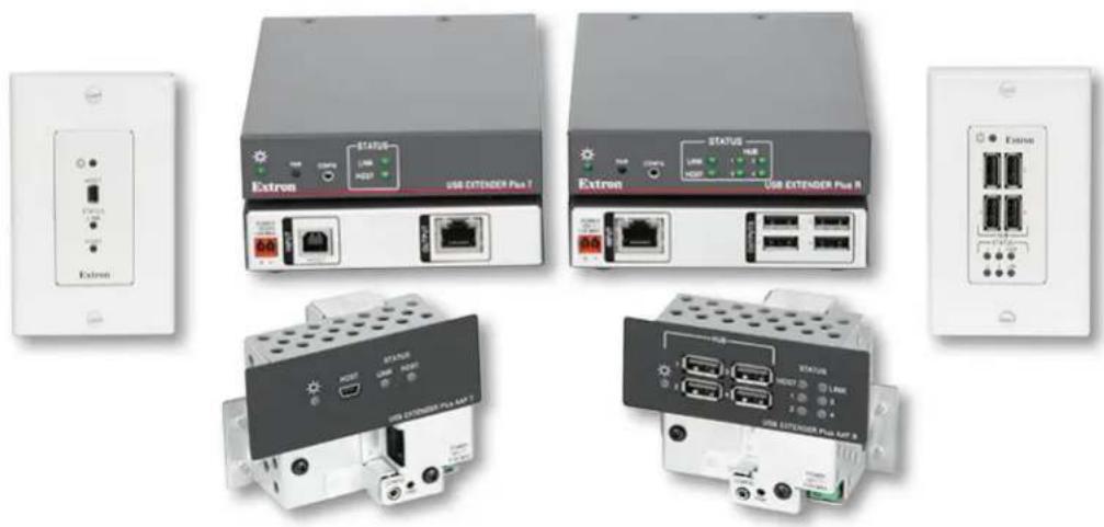
Exterior view of various network equipment units including Extran, USB EXTENDER Plus 1, and USB EXTENDER Plus 2 (no visible text or symbols on devices)Safety Instructions
Safety Instructions • English
WARNING: This symbol, , when used on the product, is intended to alert the user of the presence of uninsulated dangerous voltage within the product's enclosure that may present a risk of electric shock.
ATTENTION: This symbol, when used on the product, is intended to alert the user of important operating and maintenance (servicing) instructions in the literature provided with the equipment.
For information on safety guidelines, regulatory compliances, EMI/EMF compatibility, accessibility, and related topics, see the Extron Safety and Regulatory Compliance Guide, part number 68-290-01, on the Extron website, www.extron.com.
© 2016 Extron Electronics. All rights reserved.
Trademarks
All trademarks mentioned in this guide are the properties of their respective owners. The following registered trademarks(®), registered service marks(3M), and trademarks(1M) are the property of RGB Systems, Inc. or Extron Electronics (see the current list of trademarks on the Terms of Use page at www.extron.com):
| Registered Trademarks ^® |
| Extron, AVTrac, Cable Cubby, ControlScript, CrossPoint, DTP, eBUS, EDID Manager, EDID Minder, Flat Field, FlexOS, Global Configurator, Global Scripter, GlobalViewer, Hideaway, Inline, IP Intercom, IP Link, Key Minder, LinkLicense, LockIt, MediaLink, MediaPort, NetPA, PlenumVault, PoleVault, PowerCage, PURE3, Quantum, SoundField, SpeedMount, SpeedSwitch, System INTEGRATOR, TeamWork, TouchLink, V-Lock, VersaTools, VN-Matrix, VoiceLift, WallVault, WindoWall, XTP, and XTP Systems |
| Registered Service Mark ^(SM) : S3 Service Support Solutions |
| Trademarks ^(TM) |
| AAP, AFL (Accu-Rate Frame Lock), ADSP (Advanced Digital Sync Processing), Auto-Image, CableCover, CDRS (Class D Ripple Suppression), DDSP (Digital Display Sync Processing), DMI (Dynamic Motion Interpolation), Driver Configurator, DSP Configurator, DSVP (Digital Sync Validation Processing), eLink, Entwine, EQIP, FastBite, FOX, FOXBOX, IP Intercom HelpDesk, MAAP, MicroDigital, Opti-Torque, ProDSP, QS-FPC (QuickSwitch Front Panel Controller), Room Agent, Scope-Trigger, ShareLink, SIS, Simple Instruction Set, Skew-Free, SpeedNav, Triple-Action Switching, True4K, Vector ^TM 4K , WebShare, XTRA, ZipCaddy, and ZipClip |
FCC Class A Notice
This equipment has been tested and found to comply with the limits for a Class A digital device, pursuant to part 15 of the FCC rules. The Class A limits provide reasonable protection against harmful interference when the equipment is operated in a commercial environment. This equipment generates, uses, and can radiate radio frequency energy and, if not installed and used in accordance with the instruction manual, may cause harmful interference to radio communications. Operation of this equipment in a residential area is likely to cause interference. This interference must be corrected at the expense of the user.
ATTENTION: The Twisted Pair Extension technology works with unshielded twisted pair (UTP) or shielded twisted pair (STP) cables; but to ensure FCC Class A and CE compliance, STP cables and STP Connectors are required.
For more information on safety guidelines, regulatory compliances, EMI/EMF compatibility, accessibility, and related topics, see the “Extron Safety and Regulatory Compliance Guide” on the Extron website.
NOTES:
- (This 1st paragraph is for TP ONLY, delete for all others products) This unit was tested with shielded I/O cables on the peripheral devices. Shielded cables must be used to ensure compliance with FCC emissions limits.
- (if only this paragraph is used, reformat to single NOTE format.) For more information on safety guidelines, regulatory compliances, EMI/EMF compatibility, accessibility, and related topics, see the “Extron Safety and Regulatory Compliance Guide” on the Extron website.
Battery Notice
This product contains a battery. Do not open the unit to replace the battery. If the battery needs replacing, return the entire unit to Extron (for the correct address, see the Extron Warranty section on the last page of this guide).
CAUTION: Risk of explosion. Do not replace the battery with an incorrect type. Dispose of used batteries according to the instructions.
Conventions Used in this Guide
Notifications
The following notifications are used in this guide:
ATTENTION:
- Risk of property damage.
- Risque de dommages matériels.
NOTE: A note draws attention to important information.
Software Commands
Commands are written in the fonts shown here:
^AR Merge Scene, ,∅p1 scene 1,1 ^B 51 ^W^C.∅
[∅1] R∅∅∅4∅∅3∅∅∅∅4∅∅∅∅8∅∅∅6∅∅ [∅2] 35 [17] [∅3]
Esc X1 * X17 * X20 * X23 * X21 CE ←
NOTE: For commands and examples of computer or device responses used in this guide, the character "∅" is used for the number zero and "O" is the capital letter "O."
Computer responses and directory paths that do not have variables are written in the font shown here:
Reply from 208.132.180.48: bytes=32 times=2ms TTL=32 C:\Program Files\Extron
Variables are written in slanted form as shown here:
ping xxx.xxx.xxx.xxx -t SOH R Data STX Command ETB ETX
Selectable items, such as menu names, menu options, buttons, tabs, and field names are written in the font shown here:
From the File menu, select New. Click the OK button.
Specifications Availability
Product specifications are available on the Extron website, www.extron.com.
Extron Glossary of Terms
A glossary of terms is available at http://www.extron.com/technology/glossary.aspx.
Contents
Introduction ...... 1
About this Guide....1
About the USB Extender Plus Series .... 1
Features 2
Application Diagrams....3
Installation and Operation ....5
Connection Guidelines....5
Rear Panel Connections 5
Transmitter Rear Panels — USB Extender Plus T, Standard and HID-only....5
Receiver Rear Panels — USB Extender Plus R, Standard and HID-only 6
Transmitter and Receiver Rear Panels — USB Extender Plus AAP and Decora....7
Power Supply Attention Notices 9
Cabling and Setup....10
Installation Procedure 11
Pairing and Unpairing the Transmitter and Receiver (Point-to-Point Only)....12
Connecting for Serial Communication......13
Connecting over the Network 14
Pairing a Transmitter to Multiple Receivers .... 16
Enabling and Disabling Peripheral Emulation.....16
Front Panel Features....17
Transmitter Front Panels 17
Receiver Front Panels....19
System Operation....20
Troubleshooting....21
Remote Configuration and Control .....22
SIS Commands....22
Extender-initiated Message....22
Error Responses....23
Using the Command and Response Table......23
ASCII to Hexadecimal Conversion 23
Symbol Definitions 24
Command and Response Table for SIS Commands 25
Using the Configuration Software 27
Downloading the PCS Configuration Software from the Extron Website......27
Setting Up Network Operation....29
Starting the Configuration Program....30
Making Ties Using the Configuration Program 34
Reference Information ....37
Twisted Pair Cable Termination 37
Mounting the USB Extender Plus Series .... 38
Mounting USB Extender Plus Standard and HID Only....38
Mounting USB Extenders Plus AAP and D....39
Introduction
This section provides an overview of the USB Extender Plus Series User Guide and the following products:
• USB Extender Plus (rack-mountable)
• USB Extender Plus HID Only
- USB Extender Plus AAP
- USB Extender Plus D
The following topics are discussed:
- About this Guide
• About the USB Extender Plus Series - Features
About this Guide
This user guide contains information to install, configure, and operate the Extron USB Extender Plus Series transmitter and receiver pairs. Additional product information can be found on the Extron Electronics website at www.extron.com.
In this guide, the term "extender" refers to either the transmitter or the receiver. Where differences exist between the transmitter and receiver, they are noted. Unless otherwise specified, the product name "USB Extender Plus" refers to Extender Plus models.
About the USB Extender Plus Series
The USB Extender Plus extends signals over a single CATx twisted pair cable from USB peripheral devices that are located long distances from the host computer. It is compatible with USB 3.0, 2.0, 1.1, and 1.0 devices with a high speed data transfer rate of up to 480 Mbps.
The transmitter connects directly to a USB port on a PC or USB host and includes USB peripheral emulation to enable trouble-free booting of a host computer that is not connected to a keyboard or mouse. The receiver features a built-in active four-port hub that supplies power to multiple attached USB devices.
The transmitters and receivers are available in three form factors that can be mixed and matched:
- Rack mountable models — The USB Extender Plus models are 1 inch (2.5 cm) high, 6 inches (15 cm) deep, quarter rack wide and can be mounted to a rack or under furniture, or placed on a tabletop (see Mounting the USB Extender Plus Series on page 38).
The USB Extender Plus Human Interface Device (HID) models extend the usable distance of USB human interface peripheral devices, and card and CAC readers. HID peripherals include standard keyboards, mice, and hubs that do not require special USB device drivers. The standard and the HID-only rack-mountable transmitters have identical enclosures and connectors, as do the receivers. The only visible difference between these models is an "HID Only" label on the rear panels of the HID-only models.
- Architectural Adapter Plate (AAP) model — The USB Extender Plus AAP transmitter and receiver fit into a double-space AAP opening and is wall mountable. It can be mounted to a one-gang junction box if desired.
- Decora model — The USB Extender Plus D is a Decora ^ -style wall plate that fits into a one-gang junction box.
NOTE: The transmitter and receiver pair work with unshielded twisted pair (UTP) or shielded twisted pair (STP) cables. However, to ensure FCC Class A and CE compliance, STP cables are required.
Features
- Point-to-point long distance transmission — Extends USB peripherals up to 330 feet (100 meters) on one CAT 5/5e/6/7 cable for point-to-point applications.
- 1:N pairing over the network — One transmitter can be connected to up to four receivers.
- Extended transmission distance through network connection — Up to five gigabit network switches can be connected between the transmitter and receiver to increase the signal distance to up to 1980 feet (600 meters).
- Supports USB 3.0, 2.0, 1.1, and 1.0 devices — Supports bulk, control, interrupt, and isochronous transfers as defined by the USB specification.
- Provides data transfer rates up to 480 Mbps — Allows high speed transfer from thumb drives and other mass storage devices.
- Integrated four-port hub — The receiver has a four-port integrated USB hub, which provides 5 volts, 500 mA on each port. Allows simultaneous connection to multiple peripheral devices such as the Extron Annotator 300, mass storage devices, keyboards, mice, or other human interface devices (HID).
- Peripheral emulation — Offers increased system reliability by emulating a continuous connection between the host and an HID-compliant keyboard and mouse.
- Real-time status LED indicators for troubleshooting and monitoring — Front and rear panel LED indicators provide visual confirmation of port activity between an active host and each connected peripheral device.
- Rack and furniture mountable — Low-profile, 1-inch (2.5 cm) high, quarter rack wide metal enclosures enable the extenders to be installed discreetly, such as beneath a table or inside a lectern.
- Included power supplies — An energy-efficient, external, universal power supply, part number 70-775-01 (28-071-57LF), is provided with each unit. The power supply provides worldwide power compatibility with high demonstrated reliability and low power consumption.
- Remote configuration and control — The transmitter and receiver can be configured via Extron SIS (Simple Instruction Set) commands issued from the computer to the front panel 2.5 mm TRS Config port of the extenders.
- Choice of rack-mountable and architectural form factors — Available in a rack mountable metal enclosure, a dual AAP frame version, and a one-gang Decora-style wall plate for easy integration into a variety of environments.
- Extends human interface devices — The USB Extender Plus HID-only models extend the usable distance of smart card readers and USB human interface peripheral devices that do not require special USB device drivers, including a standard keyboard, mouse, hub, and other devices.
Application Diagrams
flowchart
graph TD
    A["Extron USB Extender Plus R\nTwisted Pair Receiver for USB Peripherals"] -->|USB| B["USB Touchscreen Display"]
    C["Extron USB Extender Plus T\nTwisted Pair Transmitter for USB Peripherals"] -->|USB| D["USB Touchscreen Display"]
    E["Extron Annotator 300\nHDCP-Compliant Annotation Processor with DTP Extension"] -->|HDMI| F["Projector/Display"]
    B -->|CAT 5/5e/6/7\nup to 330° (100m)| D
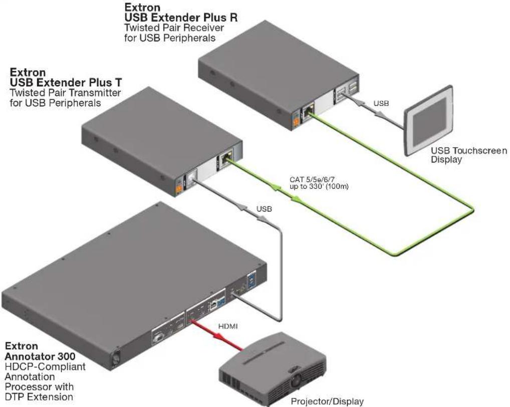
Figure 1. USB Extender Plus Application with the Annotator 300
flowchart
graph TD
    Tx["Tx"] -->|Gigabit Network Switch| Switch["Switch"]
    Switch --> Rx1["Rx 1"]
    Switch --> Rx2["Rx 2"]
    Switch --> Rx3["Rx 3"]
    Switch --> Rx4["Rx 4"]
    PC["PC (running PCS 3.3 or higher software)"] --> Switch
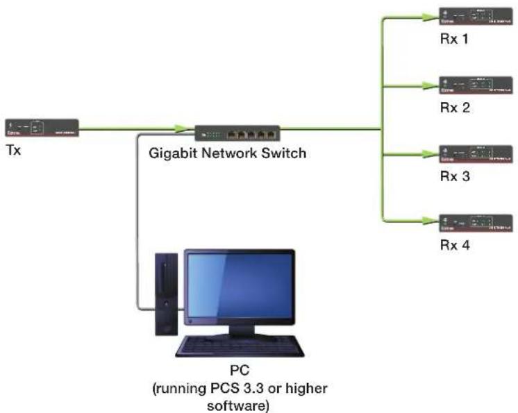
Figure 2. USB Extender Plus using a Network Connection with Multiple Receivers
flowchart
graph TD
    A["Extron USB Extender Plus D R\nTwisted Pair Extender for USB Peripherals"] -->|Up to 330 feet (100 meters)\non CAT 5/5e/6 or CAT 7 cable| B["Microcontroller with Mini B"]
    B --> C["USB Extender Plus AAP T\nTwisted Pair Extender for USB Peripherals"]
    C --> D["Laptop"]
    D --> E["Interactive Whiteboard"]
    E --> F["USB"]
    F --> G["Host"]
    F --> H["STATUS"]
    F --> I["LINK HOST"]
    F --> J["USB EXTENDER Plus AAP T"]
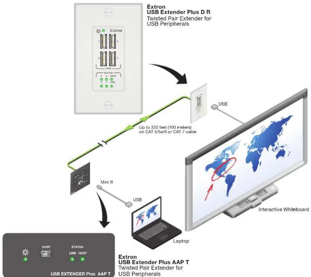
Figure 3. Application with Mixed USB Extenders Plus AAP and D Models
Installation and Operation
This section provides the following details:
- Connection Guidelines
- Rear Panel Connections
- Cabling and Setup
- Front Panel Features
- System Operation
- Troubleshooting
Connection Guidelines
The USB Extender Plus can be installed in existing and new systems within the following guidelines:
- The USB Extender Plus cannot be cascaded (you cannot sequentially connect a USB Extender Plus to another USB Extender Plus or to a FOX T/R USB Extender Plus).
- The extenders have three internal hubs, two of which can be disabled via SIS or the Product Configuration Software (PCS). The hubs that can be disabled are those for peripheral emulation and 1:N network pairing.
- The USB Extender Plus is able to support a maximum of 31 downstream USB devices (including hubs). For example, if two four-port USB hubs are connected to a receiver, that totals ten devices (two hub connections plus the eight hub ports).
- When extenders are configured for 1:N (multiple) network pairing, a transmitter can support only one high speed device at a time. For point-to-point pairing, the transmitter can support multiple high speed devices.
Rear Panel Connections
Transmitter Rear Panels — USB Extender Plus T, Standard and HID-only
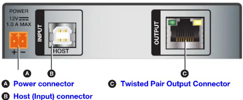
Figure 4. Transmitter Rear Panel Connectors (Rack Mountable Models)
Receiver Rear Panels — USB Extender Plus R, Standard and HID-only
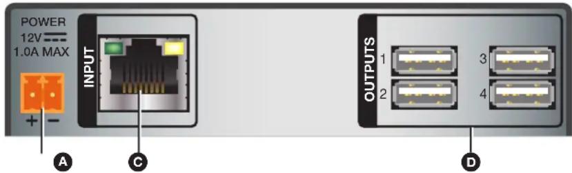
A Power connector
© Twisted Pair Input connector
USB hub connectors
Figure 5. Receiver Rear Panel Connectors (Rack Mountable Models)
Power connector — Connect a provided 12 VDC, 1 A max. external power supply to this 2-pole, 3.5 mm captive screw connector.
ATTENTION:
B Host (input) connector — Connect a USB type A to B cable between this USB type B port and the USB port of a host. The USB Extender Plus is USB 3.0 compliant and supports data transfers of 480 Mbps (high speed), 12 Mbps (full speed), and 1.5 Mbps (low speed).
© Twisted pair connector —
NOTES:
- On the transmitters, the RJ-45 connector is the output port.
-
On the receivers, the RJ-45 connector is the input port.
-
Transmitter — Connect a TP cable from the RJ-45 Input connector of the receiver (see figure 5, Ⓐ) to this female RJ-45 connector.
- Receiver — Connect a TP cable from the RJ-45 Output connector of the transmitter to this connector.
See Twisted Pair Cable Termination on page 37 to wire the RJ-45 connectors if necessary.
USB Hub connectors — The built-in four port hub has four female USB Type A connectors. The connections are USB 3.0 compatible, providing +5 VDC at up to 500 mA to connected USB peripherals requiring power.
Transmitter and Receiver Rear Panels — USB Extender Plus AAP and Decora
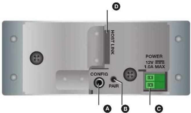
A Config port
© Power connector
B Pair button
D Twisted pair output connector
Figure 6. Rear Panel – USB Extender Plus AAP Transmitter and Receiver
ATTENTION:
NOTE: The rear panel of the USB Extender Plus AAP receiver is identical to that of the transmitter except for the function of the RJ-45 connector. On the transmitter, this connector is used for output, while on the receiver it is used for input.
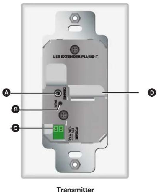
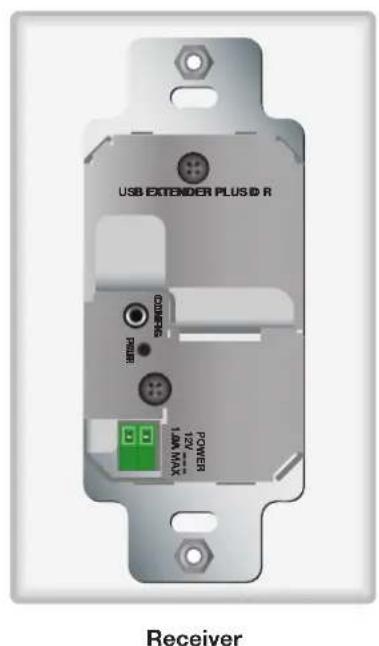
A Config port
Power connector
B Pair button
D Twisted pair output connector
Figure 7. Rear Panel – USB Extender Plus D Transmitter and Receiver
ATTENTION:
A Config port — Connect a 9-pin D-to-2.5 mm TRS cable from a computer to this 2.5 mm TRS jack for RS-232 communication (see Connecting for Serial Communication on page 13). The Config port enables serial communication with the computer for configuration and control of the transmitter via SIS commands (see Remote Configuration and Control, beginning on page 22).
NOTE: Because this connector is on the rear panel, you are not able to access it after the extender has been mounted. All communication via this port must be done before mounting.
B Pair button — This recessed button pairs the transmitter with the receiver. Use a small screwdriver or stylus to press this button (see Pairing and Unpairing the Transmitter and Receiver (Point-to-Point Only) on page 12).
NOTES:
- Pairing is required only for point to point non-network applications. For other types of applications, use PCS to set up the connection (see Using the Configuration Software, beginning on page 27, for more information).
- For point-to-point non-network applications, pairing must be done before operation the first time the transmitter and receiver are used together.
Power connector — Connect a provided 12 VDC, 1 A max. external power supply to this 2-pole, 3.5 mm captive screw connector.
ATTENTION:
Twisted pair connector — Connect a TP cable between this RJ-45 connector and that of the other unit.
- On the transmitters, the RJ-45 connector is the output port.
- On the receivers, the RJ-45 connector is the input port.
See Twisted Pair Cable Termination on page 37 to wire the RJ-45 connectors.
Power Supply Attention Notices
The following notices apply to all USB Extender Plus models:
ATTENTION:
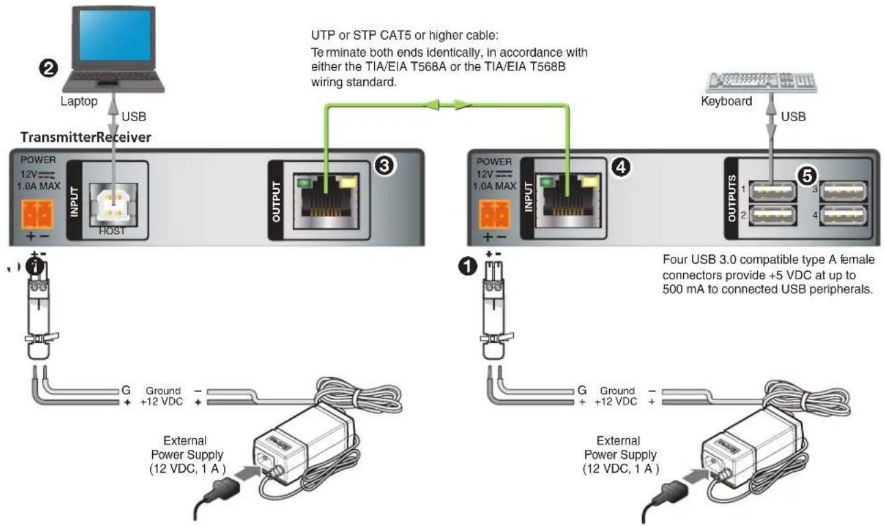
Figure 8 shows connections for the USB Extenders Plus, rack-mountable models. The connectors are the same for the AAP and Decora models except that the USB Hub connectors are on the receiver front panels and are accessible after wall mounting.
flowchart
graph TD
    A["Laptop"] -->|USB| B["TransmitterReceiver"]
    B --> C["OUTPUT"]
    C --> D["OUTPUT"]
    D --> E["OUTPUT"]
    E --> F["OUTPUT"]
    F --> G["OUTPUT"]
    G --> H["OUTPUT"]
    H --> I["OUTPUT"]
    I --> J["OUTPUT"]
    J --> K["OUTPUT"]
    K --> L["OUTPUT"]
    L --> M["OUTPUT"]
    M --> N["OUTPUT"]
    N --> O["OUTPUT"]
    O --> P["OUTPUT"]
    P --> Q["OUTPUT"]
    Q --> R["OUTPUT"]
    R --> S["OUTPUT"]
    S --> T["OUTPUT"]
    T --> U["OUTPUT"]
    U --> V["OUTPUT"]
    V --> W["OUTPUT"]
    W --> X["OUTPUT"]
    X --> Y["OUTPUT"]
    Y --> Z["OUTPUT"]
    Z --> AA["OUTPUT"]
    AA --> AB["OUTPUT"]
    AB --> AC["OUTPUT"]
    AC --> AD["OUTPUT"]
    AD --> AE["OUTPUT"]
    AE --> AF["OUTPUT"]
    AF --> AG["OUTPUT"]
    AG --> AH["OUTPUT"]
    AH --> AI["OUTPUT"]
    AI --> AJ["OUTPUT"]
    AJ --> AK["OUTPUT"]
    AK --> AL["OUTPUT"]
    AL --> AM["OUTPUT"]
    AM --> AN["OUTPUT"]
    AN --> AO["OUTPUT"]
    AO --> AP["OUTPUT"]
    AP --> AQ["OUTPUT"]
    AQ --> AR["OUTPUT"]
    AR --> AS["OUTPUT"]
    AS --> AT["OUTPUT"]
    AT --> AU["OUTPUT"]
    AU --> AV["OUTPUT"]
    AV --> AW["OUTPUT"]
    AW --> AX["OUTPUT"]
    AX --> AY["OUTPUT"]
    AY --> AZ["OUTPUT"]
    AZ --> BA["OUTPUT"]
    BA --> BB["OUTPUT"]
    BB --> BC["OUTPUT"]
    BC --> BD["OUTPUT"]
    BD --> BE["OUTPUT"]
    BE --> BF["OUTPUT"]
    BF --> BG["OUTPUT"]
    BG --> BH["OUTPUT"]
    BH --> BI["OUTPUT"]
    BI --> BJ["OUTPUT"]
    BJ --> BK["OUTPUT"]
    BK --> BL["OUTPUT"]
    BL --> BM["OUTPUT"]
    BM --> BN["OUTPUT"]
    BN --> BO["OUTPUT"]
    BO --> BP["OUTPUT"]
    BP --> BQ["OUTPUT"]
    BQ --> BR["OUTPUT"]
    BR --> BS["OUTPUT"]
    BS --> BT["OUTPUT"]
    BT --> BU["OUTPUT"]
    BU --> BV["OUTPUT"]
    BV --> BW["OUTPUT"]
    BW --> BX["OUTPUT"]
    BX --> BY["OUTPUT"]
    BY --> BZ["OUTPUT"]
    BZ --> CA["OUTPUT"]
    CA --> CB["OUTPUT"]
    CB --> CC["OUTPUT"]
    CC --> CD["OUTPUT"]
    CD --> CE["OUTPUT"]
    CE --> CF["OUTPUT"]
    CF --> CG["OUTPUT"]
    CG --> CH["OUTPUT"]
    CH --> CI["OUTPUT"]
    CI --> CJ["OUTPUT"]
    CJ --> CK["OUTPUT"]
Figure 8. USB Extender Plus T-R Connection with Two External Power Supplies
Installation Procedure
ATTENTION:
To ensure proper operation, the transmitter, receiver, USB host, and USB peripherals must be connected properly and in the sequence described here (see figure 8 on the previous page).
- Power off all devices that will be directly connected to the receiver.
- Wire the two provided power supplies to the 2-pole captive screw connectors (see figure 8, ①) on the rear panels of the transmitter and of the receiver.
- Rack mountable models — The USB Extender Plus standard and HID Only models are provided with power supplies to which 2-pole captive screw plugs are wired. Plug these connectors into the rear panel captive screw connectors of the transmitter and receiver. If it is necessary to wire a power supply to its connector, see figure 9.
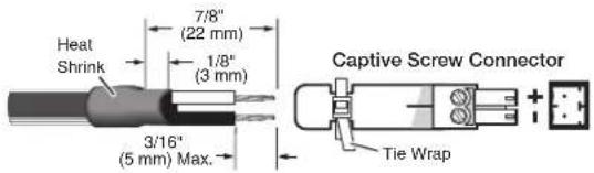
Figure 9. Wiring the Power Connector for the USB Extender Plus, Rack Mountable Models
- AAP and Decora models — These models have green insertion type 2-pole captive screw connectors on their rear panels. The power supply cables are terminated with bare wire. Insert the wires directly into the rear panel captive screw connector, as shown in figure 10.
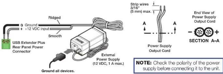
Figure 10. Wiring the Power Connectors for the AAP and Decora Models
The green power LED (shown at right) on the front panel of each extender lights.

- Connect a USB Type A-B cable from a USB port of the host computer to the transmitter Host port (2). Shortly after, the receiver Host LED (shown at right) starts blinking, indicating that communication between the USB and host has been established.

AAP and Decora Models

Rack-mountable Models
-
Connect a CATx twisted pair cable from the RJ-45 Output port of the transmitter (3) to the Input port of the receiver (4).
-
Pair the transmitter with the receiver (see Pairing and Unpairing the Transmitter and Receiver [Point-to-Point Only]). When the pairing process is complete, the Link LEDs on the front panels of the transmitter and receiver light (shown at right).
LINK

AAP and Decora Models

Rack-mountable Models
-
If appropriate, choose a location and mount the transmitter and receiver (see Mounting the USB Extender Plus Series on page 38).
-
For rack mounting, fasten the enclosure to the rack or rack shelf.
- For furniture mounting, attach units to the mounting brackets (not included), then fasten the brackets to the furniture.
- For table mounting, attached the provided four rubber feet to the bottom of the unit and place it where desired.
-
For wall mounting (AAP and Decora models only), install the junction boxes, mud rings, mounting frames, or AAP frames, following the instructions provided by the manufacturer. Attach the units to the frames.
-
Power on the host computer. On the transmitter, the Host LED on the front panel and the green Activity LED on the rear panel RJ-45 LAN connector light when the computer recognizes the transmitter. When the transmitter and receiver are paired with each other, the front panel Link LEDs light on both the transmitter and receiver.
- Connect up to four USB cables from peripheral devices (such as a keyboard, mouse, scanner, or printer) to the receiver Hub ports (see figure 8, 5, on page 10). When the first device is connected, the Host LED stops blinking and remains lit steadily.
As each peripheral device is connected, the LED for its hub port lights when the host PC detects the device.
- If desired, connect a 9-pin D-to-2.5 mm TRS cable between a computer and the front panel Config port on the transmitter, receiver, or both to configure the units via SIS commands (see Connecting for Serial Communication on page 13).
The system is now ready to operate.
Pairing and Unpairing the Transmitter and Receiver (Point-to-Point Only)
In order to function together, the transmitter and receiver must be paired the first time they are used together. Both units must be connected together through their RJ-45 connectors (the transmitter Output connector and the receiver Input connector) and powered on.
NOTES:
- Pairing and unpairing via the pair button is required only for point-to-point non-network applications.
- Before pairing a transmitter to a receiver, Extron recommends that you unpair and cycle power to each unit in order to clear any previous pairing or to resolve any pairing issues that might occur (see “Unpairing the transmitter and receiver”).
Unpairing the transmitter and receiver
To unpair a transmitter and receiver that have been paired together:
- Press and hold the Pair button on either the transmitter or receiver until the transmitter or receiver Link LED turns off (approximately 10 seconds) and the Link LED on the receiver begins to blink.
- Release the Pair button.
- Repeat steps 1 and 2 for each transmitter and receiver.
- Proceed with the pairing (see Pairing the transmitter and receiver on the next page).
Pairing the transmitter and receiver
You can initiate pairing from either the transmitter or the receiver (the procedure described below is for transmitter-to-receiver pairing). To pair the transmitter and receiver:
- Using a stylus or small screwdriver, press the recessed Pair button on the transmitter front panel and hold it for 1 second. The front panel Link LED on the transmitter begins blinking as pairing is initiated.
- Within 10 minutes of pressing the transmitter Pair button, press the receiver Pair button and hold it for 1 second. The receiver front panel Link LED begins to blink.
When the LEDs of both units have stopped blinking and remain lit steadily, the pairing is complete.
NOTES:
- After they have been paired, the transmitter and receiver can be powered down and disconnected from each other.
- A transmitter and receiver need to be paired only once (at startup). If the paired units are reconnected and powered on, they do not have to be paired again.
- For the AAP and Decora models, be sure to perform this procedure before mounting the units.
Canceling pairing
To stop the pairing process before it completes, do either of the following:
- Do not perform step 2 of the pairing process described above (that is, do not press the Pair button within 10 minutes).
- Press the transmitter Pair button and hold it for 1 second. The Link LED turns off.
Connecting for Serial Communication
The Config ports on both the transmitter and the receiver enable communication with a computer via an RS-232 connection.
NOTE: On the rack-mountable models (USB Extender Plus standard and HID-only), the Config port is on the front panel and easily accessible.
On the AAP and Decora models, the Config port is on the rear panel, so that it is not available after the unit is mounted. Any configuration via this port must be done before the product is mounted.
To enable serial communication, connect a 9-pin D-to-2.5 mm cable (not included) from the computer serial port to the Config port on the transmitter or receiver. You can enter SIS commands at the computer and issue them to the transmitter or receiver to control and configure the unit. The port protocol is 9600 baud, 8 data bits, 1 stop bit, and no parity.
An optional 9-pin D-to-2.5 mm TRS configuration cable is available from www.extron.com and can be used to connect your computer to this port. Figure 11 shows the configuration and pin assignments of this cable.
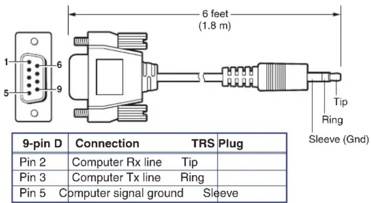
Figure 11. Optional 9-pin D to 2.5 mm TRS Cable for the Config Port
Connecting over the Network
For increased signal distance or to connect to a 1:N application, you can connect one to five gigabit network switches between the Ethernet ports of a transmitter and receiver.
- Extron recommends that gigabit network switches be used with the USB Extender Plus series in a network application. Although 10/100 network switches can be used, they allow only low and full speed USB devices such as mouse and keyboards to function correctly. No more than five network gigabit switches can be used between the transmitter and receiver.
- The USB Extender Plus series uses Layer-3 (TCP/IP) for pairing and Extron PCS, and Layer-2 (UDP, MAC address) for communication and USB data transfer. Because of this IGMP is not required or used.
- Each network switch that is added between the transmitter and receiver adds latency or degrades the signal, which may cause USB devices to function incorrectly. If a network switch being used features Quality of Service (QoS), it can reduce the effect of network congestion. However, it may not be effective in counteracting the latency that each network switch adds.
- The USB Extender Plus series is compatible with both managed and unmanaged network switchers.
- Multicast and Unicast do not apply to the USB Extender Plus series. This series features its own proprietary technology when the 1:N feature is enabled.
- Traffic and communication to one receiver is not broadcast by the transmitter to all receivers. Each packet from a transmitter is designated to a single receiver with specific MAC address.
- The USB Extender Plus series is compatible with both IPV4 and IPV6.
- USB Extender Plus models used in a network application and the PC running the PCS software must all be on the same subnet and network.
-
USB Extender Plus models that are used in a network application should be on their own independent network to keep latency low. If the latency gets too high then packets are lost or take too long and the USB protocol falls apart.
-
When using the USB Extender Plus series over-the-network or 1:N pairing, you can use only one high speed device at a time to one transmitter. High speed USB devices include webcams, audio devices, external hard drives, and so on.
- Each unit (transmitter or receiver) stores MAC addresses of every unit it pairs with (up to four for transmitters and one for receivers). You can have multiple transmitter and receivers connected to your system, and each transmitter be paired with up to four receivers. However, a receiver cannot be paired to more than on transmitter.
- The Extron PCS software is recommended for use during initial pairing and when configuring the IP address, subnet mask, and gateway address of each unit (transmitter or receiver) being used in a network application.
Network connection examples
Each unit can be connected and placed up to 330 feet (100 meters) from the switch for a total distance of 660 feet (200 meters), as shown in the example in figure 12.

flowchart
graph LR
    A["Extron"] -->|330' (100 m)| B["Gigabit Network Switch"]
    B -->|330' (100 m)| C["Rx"]
    D["Extron"] -->|Max Distance = 660' (200 m)| C
    style A fill:#f9f,stroke:#333
    style C fill:#bbf,stroke:#333
Figure 12. Network Connection with One Switch
Adding up to five network switches between the two units can increase the signal distance to up to 1980 feet (600 meters). See figure 13 for an example of a multiple switch configuration.

flowchart
graph LR
    Tx["Tx"] -->| (330') | Switch1["Switch #1"]
    Switch1 -->| (330') | Switch2["Switch #2"]
    Switch2 -->| (330') | Switch3["Switch #3"]
    Switch3 -->| (330') | Switch4["Switch #4"]
    Switch4 -->| (330') | Switch5["Switch #5"]
    Switch5 -->| (330') | Rx["Rx"]
    MaxDistance["Max Distance = 1,980'"] --> Switch4
Figure 13. Network Connection using Multiple Switches
Pairing a Transmitter to Multiple Receivers
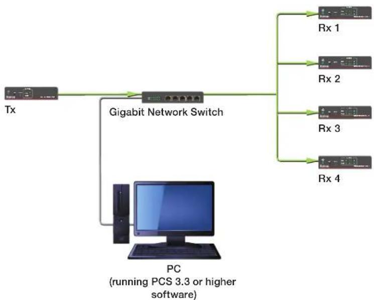
You can also connect a transmitter and up to four receivers to a network switch, then tie (pair) the transmitter to the connected receivers using the Extron PCS Control Program. The computer communicates with all connected USB Extenders via the network and makes ties through their hardware (MAC) addresses (see the example in figure 14).
flowchart
graph TD
    Tx["Tx"] -->|Gigabit Network Switch| Rx1["Rx 1"]
    Tx -->|Gigabit Network Switch| Rx2["Rx 2"]
    Tx -->|Gigabit Network Switch| Rx3["Rx 3"]
    Tx -->|Gigabit Network Switch| Rx4["Rx 4"]
    PC["PC (running PCS 3.3 or higher software)"] --> Rx1
    PC --> Rx2
    PC --> Rx3
    PC --> Rx4
Figure 14. Tying a Transmitter to Four Receivers using a Network Connection
See Using the Configuration Software on page 27 to download the program and use it to tie the transmitter to the receivers.
Enabling and Disabling Peripheral Emulation
The transmitter can be set up to emulate a mouse and keyboard to the host computer that is connected to the transmitter Host input port. This allows the computer to boot up in the event that it requires a USB keyboard or mouse to be present.
NOTE: A USB extender with peripheral emulation enabled has three hubs internally (two hubs with peripheral emulation disabled). Additional hubs may be on the host PC.
Using SIS commands, you can disable and enable peripheral emulation. By default, peripheral emulation is enabled. The following peripheral emulation commands can be issued to the transmitter only:
• To disable: Esc E ∅ USBC←
• To enable: Esc E 1 USBC←
See Remote Configuration and Control, beginning on page 22, for information on entering SIS commands.
Front Panel Features
Transmitter Front Panels
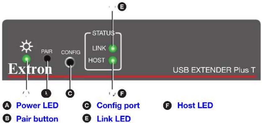
Figure 15. Transmitter Front Panel, Rack-mountable Models
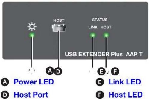
Figure 16. Transmitter Front Panel, AAP Model
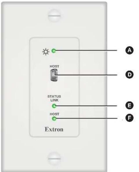
A Power LED
E Link LED
D Host port
F Host LED
Figure 17. Transmitter Front Panel, D Model
Power LED — This green LED lights to indicate that the unit is receiving power.
B Pair button — This recessed button pairs the transmitter with the receiver. Use a small screwdriver or stylus to press this button (see Pairing and Unpairing the Transmitter and Receiver (Point-to-Point Only) on page 12).
NOTES:
- Pairing is required only for point to point non-network applications. For other types of applications, use PCS to set up the connection (see Using the Configuration Software, beginning on page 27, for more information).
- For point-to-point non-network applications, pairing must be done before operation the first time the transmitter and receiver are used together.
C Config port — (Rack-mountable models only) Connect a 9-pin D-to-2.5 mm TRS cable from a computer to this 2.5 mm TRS jack for RS-232 communication (see Connecting for Serial Communication on page 13). The Config port enables serial communication with the computer for configuration and control of the transmitter via SIS commands (see Remote Configuration and Control, beginning on page 22).
Host (input) port — (AAP and D models only) Connect a USB type A to mini-B cable from a computer USB port to this USB mini-B connector. The USB Extender Plus is USB 3.0 compliant and supports data transfers of 480 Mbps (high speed), 12 Mbps (full speed), and 1.5 Mbps (low speed).
E Link LED — This green LED lights when the transmitter and receiver are successfully paired, connected together by the twisted pair cabling, and receiving power.
While the transmitter is being paired with the receiver, this LED blinks. When the pairing process is completed, the LED lights steadily.
Host LED — This green LED lights when the transmitter is powered and is communicating with the host PC.
Receiver Front Panels
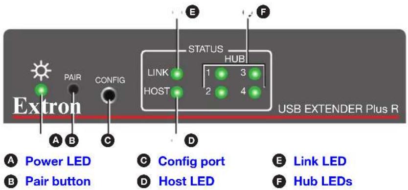
Figure 18. Receiver Front Panel, Rack-mountable Models
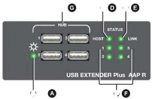
A Power LED
D Host LED
E Link LED
F Hub LEDs
G USB Hub connectors
Figure 19. Receiver Front Panel, AAP Models
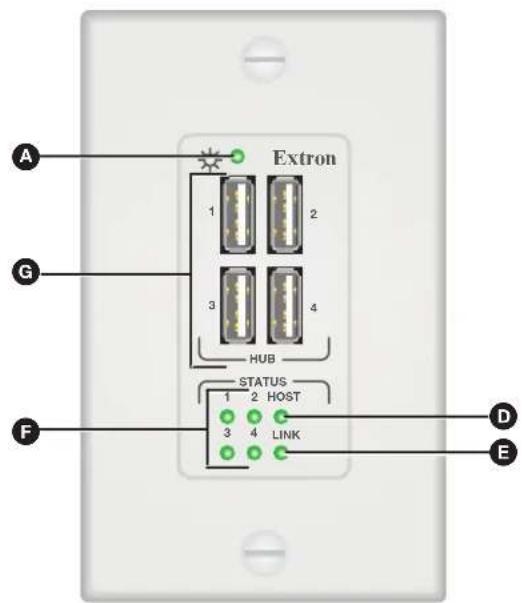
A Power LED
D Host LED
E Link LED
F Hub LEDs
G USB Hub connectors
Figure 20. Receiver Front Panel, Decora Models
Power LED — This green LED lights to indicate that the unit is receiving power.
B Pair button — This recessed button pairs the receiver with the transmitter, which must be done before operation the first time they are used together. Use a small screwdriver or stylus to press it (see Pairing and Unpairing the Transmitter and Receiver (Point-to-Point Only) on page 12).
Config port — (Rack-mountable models only) Connect a 9-pin D-to-2.5 mm TRS cable from a computer to this 2.5 mm TRS jack for RS-232 communication (see Connecting for Serial Communication on page 13). The Config port enables serial communication with the computer for configuration and control of the receiver via SIS commands (see Remote Configuration and Control, beginning on page 22).
Host LED — This green LED blinks when both the transmitter and receiver are powered, both are correctly connected by the twisted pair cable, and the receiver is communicating with the host PC.
Blinks when the transmitter and receiver are both powered and connected, but no USB devices are connected.
E Link LED — This green LED lights when the transmitter and receiver are successfully paired, connected together by the twisted pair cabling, and receiving power.
While the receiver is being paired with the transmitter, this LED blinks. When the pairing process is completed, the LED lights steadily.
F Hub LEDs — A single green LED for each port lights when the peripheral device connected to the associated USB port is recognized by the host PC.
USB Hub connectors — The built-in four port hub has four female USB Type A connectors. The connections are USB 3.0 compatible, providing +5 VDC at up to 500 mA to connected USB peripherals requiring power.
System Operation
No drivers are required for a host PC to function with the USB Extender Plus. The transmitter is detected by the operating system and appropriate USB drivers are loaded. Certain USB peripherals, such as gaming keyboards, USB interactive white boards, scanners, printers, and similar devices, require specific drivers installed on the PC. See the USB device installation instructions or the website of the peripheral device manufacturer to obtain drivers.
Once the transmitter, the receiver, the PC or USB host, and peripherals are connected, have appropriate drivers loaded, and are powered up, the system is fully operational. If problems are encountered, ensure all cables are routed and connected properly and the latest drivers for each peripheral are installed.
Troubleshooting
USB signals are generally reliable but are susceptible to bad connections or cables that are too long. The TP cable can have the same issues. To avoid the loss of data and communications, follow these guidelines:
- The USB cables that connect the transmitter to the host or the receiver hub ports to peripheral devices should not exceed 6 feet (1.8 meters).
- When connecting the host or peripherals, use only cables designed for USB signals.
- Avoid or limit the use of adapters.
- The USB Extender Plus works as described in point-to-point applications. Do not use additional adapters, patch panels, or couplers with the host USB cables, hub USB cables, or twisted pair cables. Additional links in the signal chain can result in the reduction of signal integrity and overall system performance.
When properly connected and operating, the transmitter and receiver Power LEDs, Link LEDs and Host LEDs are lit. The Hub LED for each connected peripheral recognized by the host PC is also lit.
Front panel LEDs are also useful for troubleshooting. The following table outlines operating details indicated by the LEDs:
| Transmitter Receiver | ||||
| LED Indicator | On Off On Off | |||
| Power | 12 VDC power supply is connected and operating properly. | 12 VDC power supply is not connected or is defective. | 12 VDC power supply is connected and operating properly. | 12 VDC power supply is not connected or defective. |
| Link | Both transmitter and receiver are paired, have power, and are connected properly by the TP cable. | If both Power LEDs are on, the TP cable is not connected or is improperly wired, or the units are not paired.If either Power LED is off, see the Power LED troubleshooting instructions, above. | Both transmitter and receiver are paired, have power, and are connected properly by the TP cable. | If both Power LEDs are on, the TP cable is not connected or is improperly wired, or the units are not paired.If either Power LED is off, see the Power LED troubleshooting instructions, above. |
| Host | When transmitter power LED is on, lights when communication with host PC is established. | If transmitter power LED is on, USB cable is not connected. | Lights when communication with host PC is established.Blinks if power and Link LEDs are on, but no USB devices are connected. | Host USB port is not connected or host is not communicating. |
| Hub | N/A N/A Lights when a connected | peripheral is recognized by the host PC. | A peripheral device connected to the USB port has not been recognized or is improperly connected. | |
Remote Configuration and Control
This section describes the connection through which the USB Extender Plus can be configured and controlled remotely via Simple Instruction Set (SIS) commands, and describes the commands that are available. Topics include:
- SIS Commands
• Using the Command and Response Table
• Command and Response Table for SIS Commands
SIS Commands
Using SIS commands, you can remotely set up and control the USB Extenders Plus via a host computer or other device (such as a control system) that is attached to the Config port or to the front panel Host port (AAP and Decora models only). If the computer, transmitter, and receiver are connected to a gigabit network switch for a network connection, SIS commands can be sent over Ethernet. You can issue SIS commands to the extender using a communication software program such as Extron DataViewer or HyperTerminal.
NOTE: The SIS command for resetting must be issued to both the transmitter and the receiver. Do not reset one unit without resetting the other.
SIS commands consist of one or more characters per field. No special characters are required to begin or end a command sequence. When the USB Extender Plus determines that a command that was entered is valid, it executes the command and sends a response to the host device.
Most responses from the USB Extender Plus to the host computer end with a carriage return and a line feed (CR/LF = ←), which signals the end of the response character string. A string is one or more characters.
Extender-initiated Message
When power is applied to the extender or after the unit has been reset via SIS, it sends the following copyright message:
(C) Copyright 20nn, Extron Electronics, USB Extender Plus Series, Vn.nn, 60-nnnn-nn
where Vn.nn is the firmware version number and 60-nnnn-nn is the unit part number.
NOTE: This message is displayed only when power is applied to the extender while it is connected to the computer via the Config port.
Error Responses
If the extender is unable to execute a command it receives because the command is invalid or contains invalid parameters, the USB Extender Plus returns an error response to the host. The error response codes for USB Extender Plus include:
E10 — Invalid command
E12 — Invalid port number
E13 — Invalid parameter
E14 — Not valid for this configuration
E22 — Busy
E24 — Privilege violation
E25 — Device not present
Using the Command and Response Table
The Command and Response Table on page 25 lists valid ASCII command codes, the responses of the extender to the host, and descriptions of the command functions or the results of executing the commands.
ASCII to Hexadecimal Conversion
The ASCII to Hex Conversion Table below is for use with the Command and Response Table.
| ASCII to HEX Conversion Table | Esc 1B | CR ∅D | LF ∅A | |||||||
| Space | 20 | ! | 21 | " | 22 | # | 23 | $ 24 | % 25 | & 26 |
| ( 28 ) | 29 | * | 2A | + | 2B | , 2C | - 2D | • 2E | / 2F | |
| ∅ | 30 | 1 | 31 | 2 | 32 | 3 | 33 | 4 34 | 5 35 | 6 36 |
| 8 | 38 | 9 | 39 | : | 3A | ; | 3B | < 3C | = 3D | > 3E |
| @ | 40 | A | 41 | B | 42 | C | 43 | D 44 | E 45 | F 46 |
| H | 48 | I | 49 | J | 4A | K | 4B | L 4C | M 4D | N 4E |
| P | 50 | Q | 51 | R | 52 | S | 53 | T 54 | U 55 | V 56 |
| X | 58 | Y | 59 | Z | 5A | [ | 5B \ 5C | ] 5D | ^ 5E | _ 5F |
| ` | 60 | a | 61 | b | 62 | c | 63 | d 64 | e 65 | f 66 |
| h | 68 | i | 69 | j | 6A | k | 6B | 6C | m 6D | n 6E | o 6F |
| p | 70 | q | 71 | r | 72 | s | 73 | t 74 | u 75 | v 76 |
| x | 78 | y | 79 | z | 7A | { | 7B | 7C} | 7D | ~ 7E | DEL 7F |
Symbol Definitions
← = CR/LF (carriage return and line feed) (hex ∅D ∅A)
← = Soft carriage return (no line feed)
- = Space
Esc = Escape key (hex 1B)
[X1] = On and off (enable and disable)
∅ = Off or disabled
1 = On or enabled
x2 = Extender unit part number:
Transmitter: 60-1471-12
Receiver: 60 - 1471 - 13
HID Only Transmitter: 60-1539-12
HID Only Receiver: 60-1539-13
AAP Transmitter, black: 60-1472-12
AAP Transmitter, white: 60-1472-13
AAP Receiver, black: 60-1472-22
AAP Receiver, white: 60-1472-23
Decora Transmitter: 60 - 1473 - 13
Decora Receiver: 60-1473-23
x3 = IP address (Default is 192.168.254.254.)
[X4] = Subnet mask (Default is 255.255.0.0.)
[X5] = Gateway IP address (Default is ∅.∅.∅.∅.)
X6 = Port number for Config port (Default is 6137.)
NOTE: Unless otherwise indicated, commands are not case-sensitive.
Command and Response Table for SIS Commands
| Command | ASCII Command (Host to Unit) | Response (Unit to Host) | Additional Description |
| Information Requests | |||
| Request part number | N | 2 | Show the extender part number 2 . For 2 :Transmitter: 60-1471-12Receiver: 60-1471-13HID Only Transmitter: 60-1539-12HID Only Receiver: 60-1539-13AAP Transmitter, black: 60-1472-12AAP Transmitter, white: 60-1472-13AAP Receiver, black: 60-1472-22AAP Receiver, white: 60-1472-23Decora Transmitter: 60-1473-13Decora Receiver: 60-1473-23 |
| Query firmware version | Q | n.nn | Show the firmware version, expressed to the second decimal place. |
| Example: | Q | 1.01 | The unit firmware version is 1.01. |
| Query firmware version and build | *Q | n.nn.nnnn | Show firmware version and build number. |
| Peripheral Emulation (Transmitters Only) | |||
| NOTE: These commands can be issued only to the transmitter. | |||
| Set peripheral emulation | Esc E X1 USBC | Usbc E X1 | Set peripheral emulation for the USB Extender Plus T to 1 . For 1 : = disabled1 = enabled (default) |
| View peripheral emulation | Esc E USBC | 1 | |
| Network Pairing | |||
| Enable 1:N network pairing | Esc N X1 USBC | Usbc N X1 | Enable or disable pairing of the transmitter with receivers via the network. For 1 : = pairing disabled1 = pairing enabled (default) |
| View 1:N network pairing | Esc N USBC | 1 | |
| Resetting | |||
| NOTE: This command must be issued to both the transmitter and the receiver. | |||
| Reset device settings to factory defaults | Esc ZXXX | Zpx | Reset the extender to factory default values while retaining pairing and IP settings. |
| Absolute system reset | Esc ZQQQ | Zpq | Reset all extender settings to factory defaults except firmware version. |
| Upload Firmware | |||
| Upload firmware | Esc UPLOAD | ...goUp1 | Up1 is displayed after the upload is complete. |
| Network Settings | |||
| Set DHCP mode | Esc X1 DH ← | Idh X1 ← | Enable or disable Dynamic Host Configuration Protocol (DHCP) automatic assignment of IP addresses. For X1:∅ = DHCP disabled (default)1 = DHCP enabled |
| Esc DH ← | X1 ← | Show current DHCP status X1. | |
| Set IP address | Esc X2 CI ← | Ipi • X2 ← | Set IP address X2 for the unit.Default: 192.168.254.254. |
| View IP address | Esc CI ← | X2 ← | Show the current unit IP address. |
| Set subnet mask | Esc X4 CS ← | Ips • X4 ← | Set subnet mask X4 for the unit.Default: 255.255.∅.∅. |
| View subnet mask | Esc CS ← | X4 ← | Show the current subnet mask for the unit. |
| Set gateway IP address | Esc X5 CG ← | Ipg • X5 ← | Set gateway address X5 for the unit.Default: ∅.∅.∅.∅ |
| View gateway address | Esc CG ← | X5 ← | Show current gateway address of the unit. |
| Set Config port map | Esc K X6 PMAP ← | Pmap K X6 ← | Set a port number X6 for the Config port.Default: ∅6137 |
| NOTES:Duplicate port number assignments are not permitted (for example, the Telnet and web port numbers cannot be the same). If this is attempted, an E13 error code is returned.Remapping of a port number (other than to reset it to the default ∅6137 or disable it by resetting it to ∅) must be to port numbers higher than 1024. | |||
| Reset Config port map | Esc K ∅6137 PMAP ← | Pmap K ∅6137 ← | Reset the Config port number to the factory default (∅6137). |
| Disable Config port | Esc K ∅ PMAP ← | Pmap K ∅0000 ← | Disable the Config port. |
| View Config port map | Esc K PMAP ← | X6 ← | View the current Config port number. |
Using the Configuration Software
The Extron Product Configuration Software (PCS) is a Windows-based program for the USB Extender Plus that enables you to tie (pair) the transmitter to multiple receivers (see Pairing a Transmitter to Multiple Receivers on page 16 to set up this configuration). This program is available on the Extron website.
Downloading the PCS Configuration Software from the Extron Website
To use the PCS program, download it from www.extron.com and install it on your PC as described in the following sections. You can also download updates to the PCS configuration software as they become available. To access the software:
- Open the Extron Web page and select the Download tab.
- On the Download Center screen, click the PCS link on the left sidebar menu (see figure 21, ①).
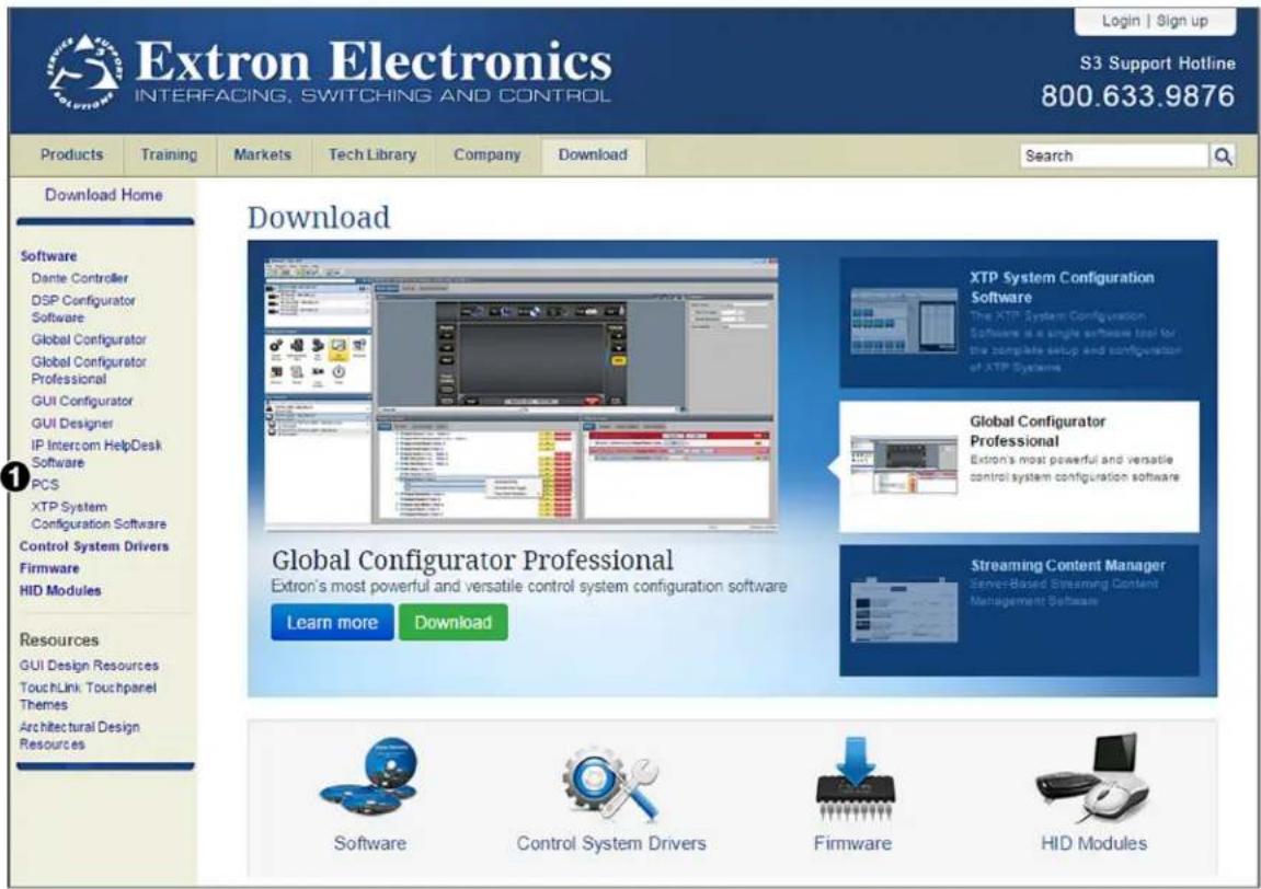
Figure 21. Software Links on the Download Page of the Extron Website
- On the PCS page, click the Download button in the table (see figure 22, 1).
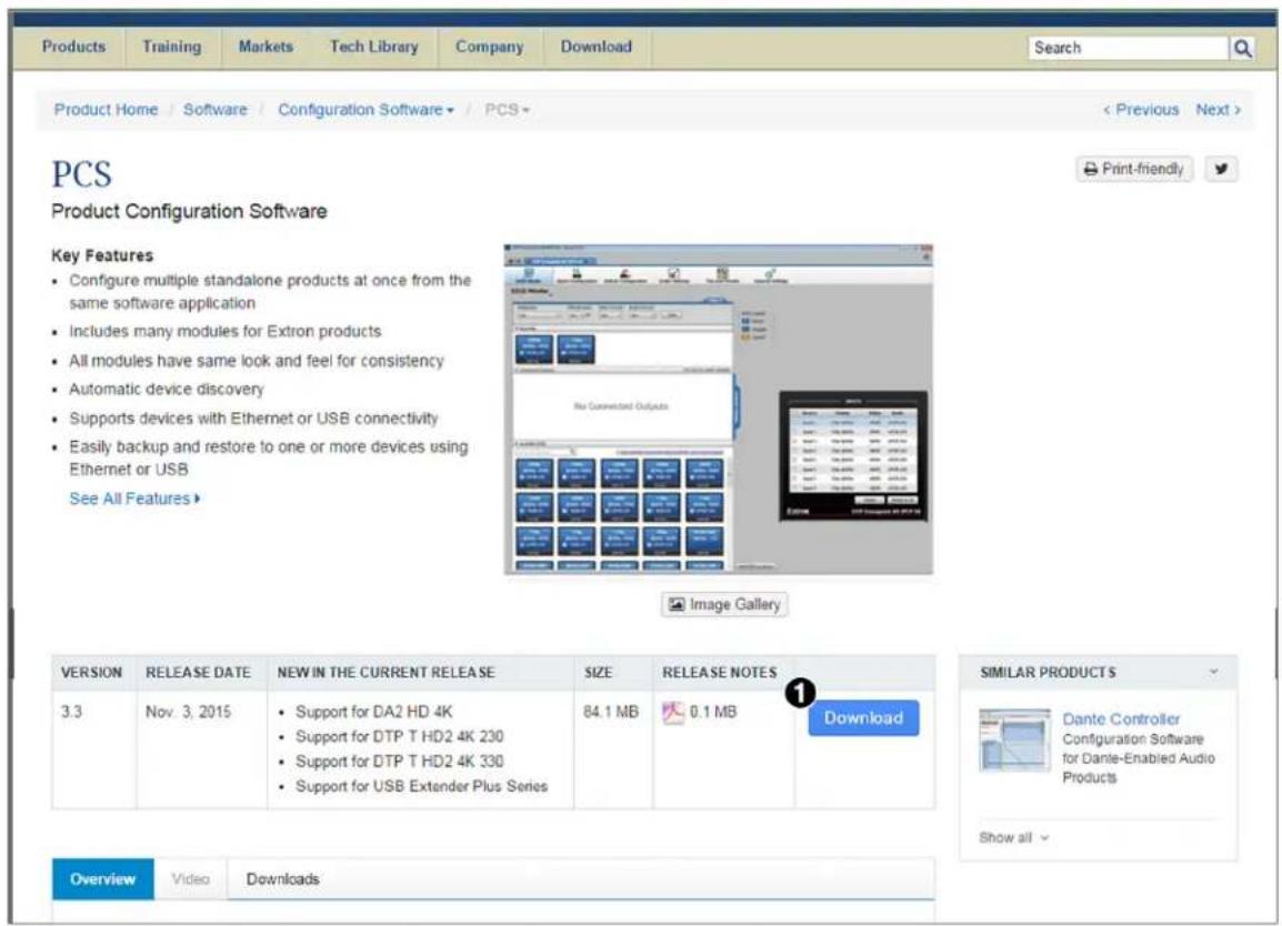
Figure 22. Download Button on the PCS Web Page
- On the Download Center screen that opens, fill in the required information, then click the Download pcss_vnxn.exe button.
- If the File Download - Security Warning window appears, click Run to begin downloading the installer file.
NOTE: If you want to save the installation file to your computer hard drive to run later, click Save. On the Save As window that opens, save the setup file to the desired location. When you are ready to install the software, double-click on the pcss_vnxnxn.exe icon, click Run on the download screen that opens, and restart this procedure at step 6.
If, instead, you see a Download icon at the bottom of the page, wait until the icon displays the name pcss_vnxnxn.exe, then click it.
- On the next prompt window that opens, click Run to start the installation process.
- Follow the instructions on the InstallShield Wizard screens to complete the software program installation. By default, the installation creates a folder called "Extron PCS" at:
c:\Program Files (x86)\Extron\Extron PCS or
c:\Program Files\Extron\Extron PCS
If there is not already an Extron folder in your Program Files folder, the installation program creates it as well.
Setting Up Network Operation
To set up the USB Extender Plus for use on the network, do the following:
- Connect the transmitter, receivers, and computer to a gigabit network switch (see figure 12 on page 15 for an example).
NOTE: The transmitter, receivers, and the PC running the PCS software must all be on the same subnet and network.
- By default, over-the-network pairing should be enabled. If it is not, enter the following SIS command to enable it:
Esc N 1 USBC ←
(See SIS Commands on page 22 for information on entering these commands.)
- Obtain the subnet mask and gateway IP address of your computer network. Either obtain this information from your system administrator, or via a Windows Command window as follows:
a. Open a Command window on your computer.
b. At the command prompt enter ipconfig. A screen similar to the example in figure 23 appears, displaying connection information for the computer.
NOTE: Before assigning network addresses, check with your system administrator to find out what IP addresses are available or appropriate for you to use.
- Record the Subnet Mask and Default Gateway addresses (see figure 23, 1).
![Microsoft Windows [Version 6.1.7601] Copyright (c) 2009 Microsoft Corporation. All rights reserved. C:\Users\Extron User>ipconfig Windows IP Configuration Ethernet adapter Bluetooth Network Connection: Media State . . . . . . . . . . . . : Media disconnected Connection-specific DNS Suffix . : Ethernet adapter Local Area Connection: Connection-specific DNS Suffix . : extron.com Link-local IPv6 Address . . . . . : fe80::2ccb:3574:137:b547%12 IPv4 Address. . . . . . . . . . . . : 192.168.254.254 Subnet Mask . . . . . . . . . . . : 255.255.240.0 Default Gateway . . . . . . . . . . : 10.113.64.100 Tunnel adapter isatap.<8F072EDC-F13D-4C03-8684-B589F683F2B5>: Media State . . . . . . . . . . . : Media disconnected Connection-specific DNS Suffix . Tunnel adapter isatap.extron.com: Media State . . . . . . . . . . . : Media disconnected Connection-specific DNS Suffix . : extron.com C:\Users\Extron User>](/content/2026/05/946324/images/3a66410fc3c62460853a805d704f19190b37fdee842dd87e9b3c5ad5ab7a00c4.jpg)
Figure 23. Command Prompt Window with IP Information
- Use the PCS configuration software or SIS commands to set the IP address, gateway address, and subnet mask as needed (see figure 27 on page 32).
Starting the Configuration Program
In order to use the PCS software, the transmitter, receivers, and computer running the PCS software must all be on the same network and must have the same subnet mask and gateway IP address (see Setting Up Network Operation on the previous page).
-
To start the PCS configuration program, do either of the following:
-
Double-click on the EAF.exe file, by default located on your computer at c:\Program Files [or Program Files(x86)]\Extron\Extron PCS.
-
Click Start > All Programs > Extron Electronics > Extron Product Configuration Software/Extron Product Configuration Software.
-
The first time you open the PCS software, a Tutorial screen appears. To close this screen, click I Get It. The Extron PCS window opens, displaying a list of all devices connected to the network.
-
Check the software version and ensure that it is 3.3 or higher. To view the software version:
a. Click the menu icon in the upper-right corner of the PCS screen and select About Extron PCS from the drop-down menu.
The following screen appears:
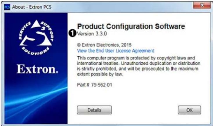
Figure 24. Software Version Number on the About PCS Screen
b. After ensuring that the software version is 3.3 or higher (see figure 24, 1), click OK to close the window.
- On the Extron PCS window, click the down arrow button in the upper-left corner (see figure 25, ①) to display the configuration drop-down menu. Select New Configuration File from this menu.
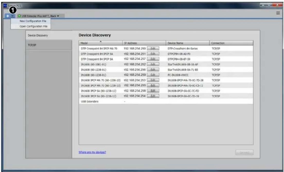
Figure 25. Selecting New Configuration File on the PCS Window
The New Configuration File dialog box opens, displaying a list of all USB Extender Plus devices on your network.
- On this list, click the name of the USB extender to be configured.
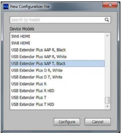
Figure 26. Selecting an Extender from the New Configuration File List
The dialog box closes and the Device Settings screen appears, with name of the selected device on a new tab at the top of the screen (see figure 27, 1).
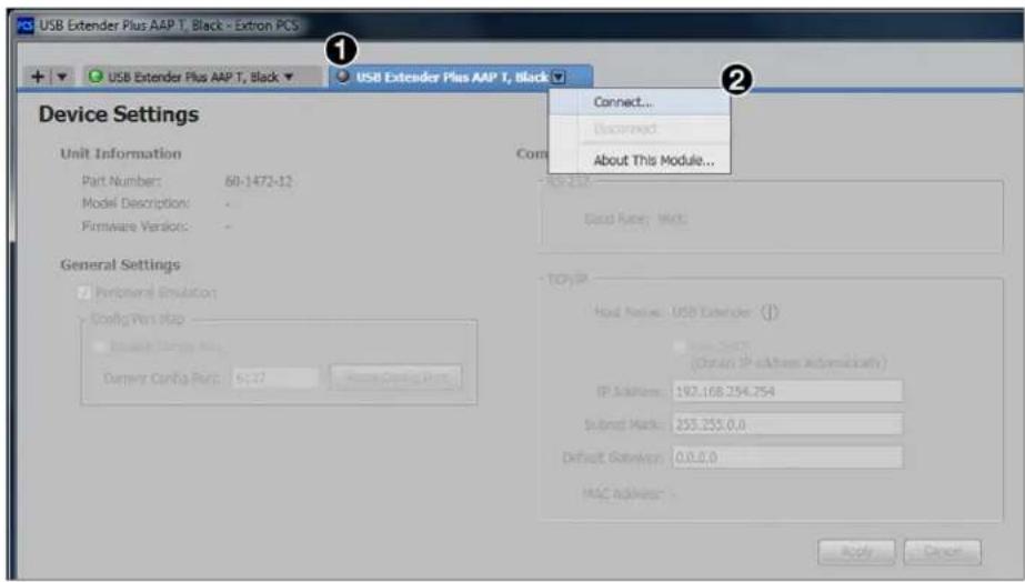
Figure 27. Selecting Connect from the Device Tab Menu
- Click the down arrow on the device tab and select Connect from the drop-down menu (2). The RS-232 Connect window opens.
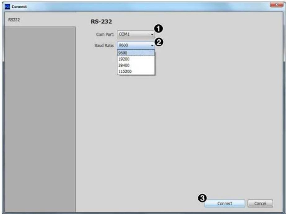
Figure 28. RS-232 Connection Window
- From the Com Port drop-down menu (see figure 28, ①), select the com port on your computer to which the USB Extender Plus is connected.
- From the Baud Rate menu (②), select the baud rate for your RS-232 connection (the default is 9600).
- Click the Connect button (③) at the bottom of the screen. The Device Settings screen for your USB Extender Plus opens, showing all the current extender settings.
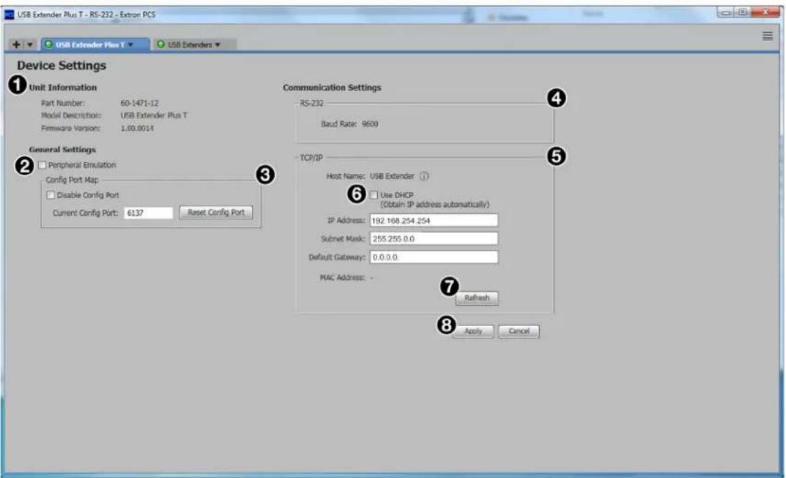
Figure 29. Device Settings Screen
Unit Information — Displays the unit part number, model name and color, and firmware build version.
② Peripheral Emulation checkbox — Select this checkbox to enable USB HID peripheral devices (keyboard or mouse) to always appear to the host computer.
③ Config Port Map panel — Contains a field in which you can change the number of the port through which the extender is connected to the network (the default port is 6137). The Reset Config Port button next to this field resets the network port number to the default.
4 RS-232 panel — Displays the connection speed (baud rate) for the front panel RS-232 Config port.
⑤ TCP/IP panel — Contains fields in which you can set the unit IP address, subnet mask, and gateway address.
⑥ Use DHCP checkbox — Select this checkbox to enable Dynamic Host Configuration Protocol (DHCP), if desired. When DHCP is enabled, the device ignores any entered IP addresses and obtains its IP address from a DHCP server. Selecting this checkbox disables all address fields in this panel.
⑦ Refresh button — Click this button to update the IP address, subnet mask, and gateway address with latest assigned addresses.
⑧ Apply button — Click this button to confirm your selections on the screen.
- Make any desired changes to the available settings and click Apply (8) when finished.
The PCS main window is displayed with the following items added:
- A new tab at the top of the screen, containing the model name of your new device
- A USB Extenders line in the Device Directory panel. (The individual USB Extender Plus devices are not listed separately.)
You can now proceed to pair the transmitter and receivers (see Making Ties Using the Configuration Program on the next page).
Making Ties Using the Configuration Program
On the USB Extenders Ties screen, you can pair (tie) each listed transmitter with one or more listed receivers. (You cannot, however, pair more than one transmitter with a receiver.)
Displaying the Ties screen
To display the Ties screen:
- If the PCS Device Discovery screen is not displayed, click the down arrow button (① in the illustration at right) in the upper-left corner of the screen to return to it.
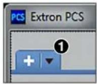
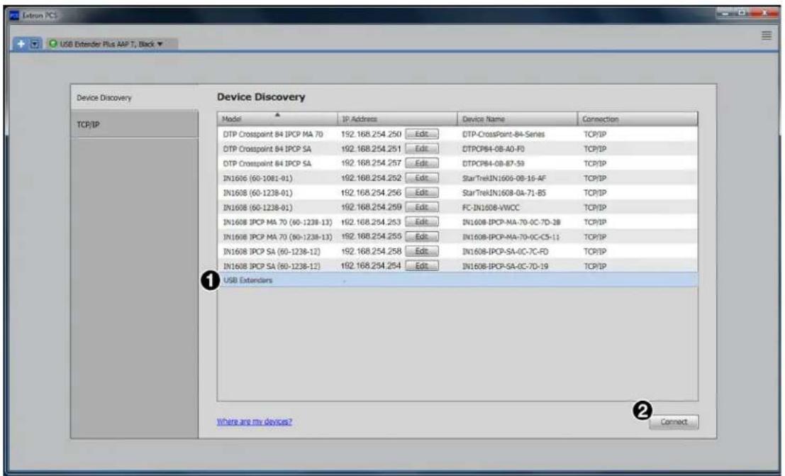
Figure 30. Selecting USB Extenders on the Device Discovery Panel
- Click USB Extenders in the Device Directory panel (see figure 30, ①).
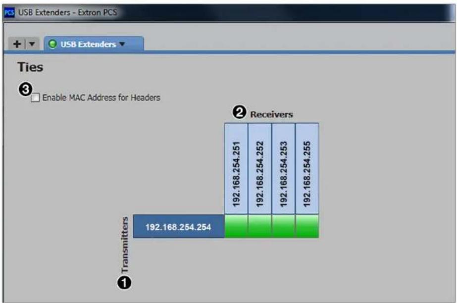
- Click Connect (②). The Ties screen appears (see figure 31 on the next page).
bar
| Component | Value | | :--- | :--- | | Transmitters | 192.168.254.254 | | Receivers | 192.168.254.251 | | Receivers | 192.168.254.252 | | Receivers | 192.168.254.253 | | Receivers | 192.168.254.255 |Figure 31. USB Extenders Ties Screen
In the table on the Ties screen, transmitters that are connected to the network are listed by their IP addresses in the rows (1). Receivers are listed in the columns (2). To list the devices by their MAC addresses instead of the IP addresses, select the Enable MAC for Headers checkbox (3).
Viewing MAC addresses on the Ties screen
If you want to view the MAC address of a transmitter or receiver without changing the entire display, hover the mouse pointer over the desired IP address to show the MAC address in a pop-up box (see figure 32, 1).
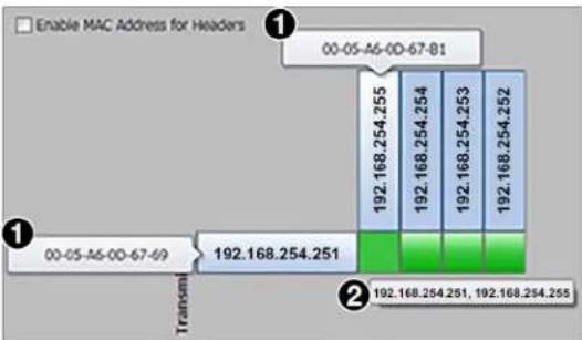
Figure 32. MAC Addresses in Pop-up Boxes
If the screen is set to display MAC addresses, you can view an individual IP address by positioning the pointer over the MAC address.
To display the addresses of tied products, hover the cursor over the green connection box in the matrix. The addresses of both tied products are displayed in a pop-up (2).
Pairing a transmitter with receivers (creating ties)
To tie a transmitter to receivers using the PCS software:
- In the matrix in the center of the screen, locate the connection box beside the desired transmitter address and below the desired receiver address.
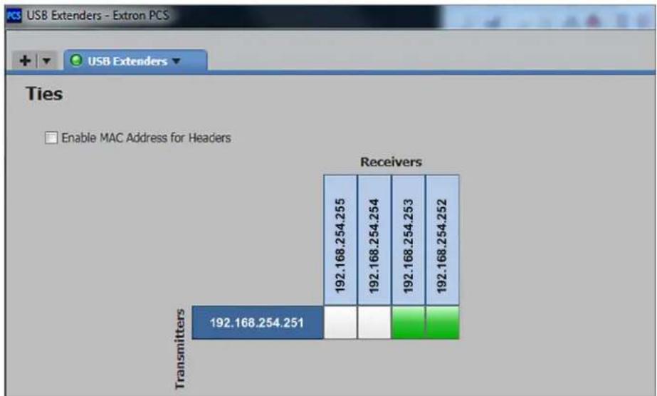
- If the box is white, click it. When the box becomes green, the transmitter and receiver are paired. Figure 33 shows a transmitter paired with two receivers.
bar_stacked
Ties Enable MAC Address for Headers | Transmitter | Receivers 192.168.254.255 | Receivers 192.168.254.254 | Receivers 192.168.254.253 | Receivers 192.168.254.252 | | :--- | :--- | :--- | :--- | :--- | | Transmitters | 192.168.254.251 | | | | | Receivers | 192.168.254.255 | 192.168.254.254 | 192.168.254.253 | 192.168.254.252 |Figure 33. Tying a Transmitter to Two Receivers
- Repeat step 2 for any additional receivers in the same row that you want to pair with the selected transmitter.
- Repeat steps 1 through 3 for any additional transmitters to which receivers will be paired.
Reference Information
This section provides information on the following subjects:
• Twisted Pair Cable Termination
- Mounting the USB Extender Plus Series
Twisted Pair Cable Termination
NOTES:
- RJ-45 termination with CAT 5, CAT 5e, CAT 6, CAT 6e, and CAT 7 cable must comply with the TIA/EIA T568A or TIA/EIA T568B wiring standard for all connections.
- The transmitter and receiver pair work with unshielded twisted pair (UTP) or shielded twisted pair (STP) cables; but to ensure FCC Class A and CE compliance, STP cables are required.
- Terminate both ends of the cable identically, in accordance with either the TIA/EIA T 568A or the TIA/EIA T 568B wiring standard.
Figure 34 shows the recommended termination of TP cables with RJ-45 connectors.
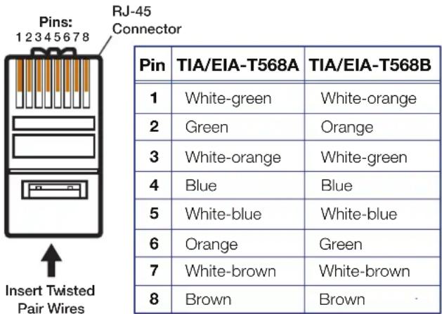
Figure 34. TP Cable Termination
NOTE: Do not use Extron UTP23SF-4 Enhanced Skew-Free AV UTP cable to link the transmitter and receiver. Skew-free AV cable is designed for Extron TP transmitter and receiver AV applications. The USB Extender Series does not work properly with this cable.
Mounting the USB Extender Plus Series
Mounting USB Extender Plus Standard and HID Only
The 6 inches (15 cm) deep, 1 inch (2.5 cm) high, quarter-rack wide USB Extender Plus transmitter and receiver can be placed on a tabletop, mounted on a rack shelf, or mounted under a desk or tabletop. See the installation instructions provided with the individual mounting kits.
Tabletop Placement
Affix the four included rubber feet to the bottom of the unit and place it in any convenient location.
Rack Mounting Safety Guidelines
The following Underwriters Laboratories (UL) guidelines pertain to the safe installation of these products in a rack:
- Elevated operating ambient temperature — If the unit is installed in a closed or multi-unit rack assembly, the operating ambient temperature of the rack environment may be greater than room ambient temperature. Therefore, install the equipment in an environment compatible with the maximum ambient temperature (Tma: +122 °F, +50 °C) specified by Extron.
- Reduced air flow — Install the equipment in the rack so that the equipment gets adequate air flow for safe operation.
- Mechanical loading — Mount the equipment in the rack so that uneven mechanical loading does not create a hazardous condition.
- Circuit overloading — Connect the equipment to the supply circuit and consider the effect that circuit overloading might have on overcurrent protection and supply wiring. Consider the equipment nameplate ratings when addressing this concern.
- Reliable earthing (grounding) — Maintain reliable grounding of rack-mounted equipment. Pay particular attention to supply connections other than direct connections to the branch circuit (such as the use of power strips).
To find an appropriate rack mounting kit for your installation, go to the product page at www.extron.com.
Furniture Mounting
The USB Extender Plus can be mounted to a desk, podium, or other furniture as follows:
- Under furniture — The unit can be mounted under a horizontal surface using an optional Under-Desk Mount Kit for eighth-rack and quarter-rack width products (see www.extron.com).
- Through furniture — The transmitter or receiver can be mounted through a desk or other furniture using an optional Extron Through-Desk Mounting Kit for quarter-rack or half-rack width products (see www.extron.com).
Mounting USB Extenders Plus AAP and D
You can install the USB Extender Plus AAP and Decora transmitter and receiver in an electrical junction box, attach them to AAP frames or mud rings, or both.
Wall mounting
Safety guidelines
The wall installation must conform to national and local electrical codes and to the wall plate size requirements. The following UL guidelines pertain to the installation of the wall mountable transmitters and receivers into a wall or furniture.
- Do not connect these units to a centralized DC power source or use beyond their rated voltage range.
• These units must be installed in UL Listed junction boxes.
• These units must be installed with conduit in accordance with National Electrical Code.
Preparing the site and installing the junction box
If installing the extender in a junction box:
- Choose a location that allows cable runs without interference.
- Allow enough depth for the wall box, the TP cable, and power supply wiring. The box should be at least 2.5 inches (6.4 cm) deep to accommodate the connectors and cables.
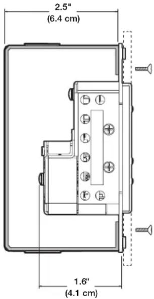
Figure 35. Wall Box Depth Profile — AAP and Decora
- Run the TP and power supply wires into the wall, furniture, or conduits before installing the wall plate.
- Follow the instructions provided with the junction box to install it.
NOTE: The Decora series mounts in a standard single-gang junction box.
Final installation
To complete the installation:
- Test the USB Extenders Plus for proper operation.
- At the power outlet (not the extender), unplug the power supply.
- Mount the transmitter or receiver into the wall box.
- At the power outlet, reconnect the power supply.
AAP mounting
The USB Extender Plus AAP transmitter and receiver can also be mounted to a two-space AAP frame, available at www.extron.com. Follow the instructions provided with the frame to attach the extenders to it.
Figure 36 shows an example of mounting both an AAP extender and a Decora extender to an AAP frame.
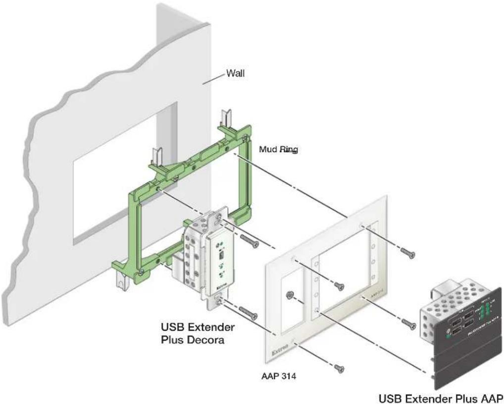
Figure 36. Mounting a USB Extender Plus AAP and Decora to an AAP Frame and a Mud Ring
Extron Warranty
Extron Electronics warrants this product against defects in materials and workmanship for a period of three years from the date of purchase. In the event of malfunction during the warranty period attributable directly to faulty workmanship and/or materials, Extron Electronics will, at its option, repair or replace said products or components, to whatever extent it shall deem necessary to restore said product to proper operating condition, provided that it is returned within the warranty period, with proof of purchase and description of malfunction to:
USA, Canada, South America, and Central America:
Extron Electronics
1230 South Lewis Street
Anaheim, CA 92805
U.S.A.
Japan:
Extron Electronics, Japan
Kyodo Building, 16 Ichibancho
Chiyoda-ku, Tokyo 102-0082
Japan
Europe and Africa:
Extron Europe
Hanzeboulevard 10
3825 PH Amersfoort
The Netherlands
China:
Extron China
686 Ronghua Road
Songjiang District
Shanghai 201611
China
Asia:
Extron Asia Pte Ltd
135 Joo Seng Road, #04-01
PM Industrial Bldg.
Singapore 368363
Singapore
Middle East:
Extron Middle East
Dubai Airport Free Zone
F13, PO Box 293666
United Arab Emirates, Dubai
This Limited Warranty does not apply if the fault has been caused by misuse, improper handling care, electrical or mechanical abuse, abnormal operating conditions, or if modifications were made to the product that were not authorized by Extron.
NOTE: If a product is defective, please call Extron and ask for an Application Engineer to receive an RA (Return Authorization) number. This will begin the repair process.
USA: 714.491.1500 or 800.633.9876
Europe: 31.33.453.4040
Asia: 65.6383.4400
Japan: 81.3.3511.7655
Units must be returned insured, with shipping charges prepaid. If not insured, you assume the risk of loss or damage during shipment. Returned units must include the serial number and a description of the problem, as well as the name of the person to contact in case there are any questions.
Extron Electronics makes no further warranties either expressed or implied with respect to the product and its quality, performance, merchantability, or fitness for any particular use. In no event will Extron Electronics be liable for direct, indirect, or consequential damages resulting from any defect in this product even if Extron Electronics has been advised of such damage.
Please note that laws vary from state to state and country to country, and that some provisions of this warranty may not apply to you.
| Extron Headquarters+1.800.633.9876 (Inside USA/Canada Only)Extron USA - West Extron USA - East+1.714.491.1500 +1.919.850.1000+1.714.491.1517 FAX +1.919.850.1001 FAX | Extron Europe+800.3987.6673(Inside Europe Only)+31.33.453.4040+31.33.453.4050 FAX | Extron Asia+65.6383.4400+65.6383.4864 FAX | Extron Japan+81.3.3511.7656+81.3.3511.7656 FAX | Extron China+86.21.3760.1568+86.21.3760.1566 FAX | Extron Middle East+971.4.299.1800+971.4.299.1880 FAX | Extron Australia+61.8.8351.2188+61.8.8351.2511 FAX | Extron India1800.3070.3777(Inside India Only)+91.80.3055.3777+91.80.3055.3737 FAX |
- USB Extender Plus Series
- Safety Instructions
- Safety Instructions • English
- Trademarks
- FCC Class A Notice
- NOTES:
- Battery Notice
- Conventions Used in this Guide
- Notifications
- ATTENTION:
- Software Commands
- Specifications Availability
- Extron Glossary of Terms
- Contents
- Introduction ...... 1
- Installation and Operation ....5
- Remote Configuration and Control .....22
- Reference Information ....37
- Introduction
- About this Guide
- About the USB Extender Plus Series
- Features
- Application Diagrams
- Installation and Operation
- Connection Guidelines
- Rear Panel Connections
- Receiver Rear Panels — USB Extender Plus R, Standard and HID-only
- Transmitter and Receiver Rear Panels — USB Extender Plus AAP and Decora
- Figure 6. Rear Panel – USB Extender Plus AAP Transmitter and Receiver
- Power Supply Attention Notices
- Installation Procedure
- Pairing and Unpairing the Transmitter and Receiver (Point-to-Point Only)
- Unpairing the transmitter and receiver
- Pairing the transmitter and receiver
- Canceling pairing
- Connecting for Serial Communication
- Connecting over the Network
- Network connection examples
- Pairing a Transmitter to Multiple Receivers
- Enabling and Disabling Peripheral Emulation
- Front Panel Features
- System Operation
- Troubleshooting
- Remote Configuration and Control
- SIS Commands
- Extender-initiated Message
- Error Responses
- Using the Command and Response Table
- ASCII to Hexadecimal Conversion
- Symbol Definitions
- Using the Configuration Software
- Downloading the PCS Configuration Software from the Extron Website
- Setting Up Network Operation
- Starting the Configuration Program
- Making Ties Using the Configuration Program
- Displaying the Ties screen
- Viewing MAC addresses on the Ties screen
- Pairing a transmitter with receivers (creating ties)
- Reference Information
- Twisted Pair Cable Termination
- Mounting the USB Extender Plus Series
- Mounting USB Extender Plus Standard and HID Only
- Tabletop Placement
- Rack Mounting Safety Guidelines
- Furniture Mounting
- Mounting USB Extenders Plus AAP and D
- Wall mounting
- Safety guidelines
- Preparing the site and installing the junction box
- Final installation
- AAP mounting
- Extron Warranty
- USA, Canada, South America, and Central America:
- Japan:
- Europe and Africa:
- China:
- Asia:
- Middle East:
Brand : Extron
Model : USB Extender Plus R
Category : Network switch