
FOX Matrix 7200 - Network switch Extron - Free user manual and instructions
Find the device manual for free FOX Matrix 7200 Extron in PDF.


| Product Type | Fiber Optic Matrix Switcher |
| Model | FOX Matrix 7200 |
| Brand | Extron |
| Maximum I/O Capacity | Up to 720 inputs and 720 outputs (modular) |
| Signal Types | Video (HDMI, DVI, RGB, component, composite), audio, and control signals over fiber |
| Fiber Connector Type | LC duplex (single-mode or multi-mode) |
| Chassis Form Factor | Modular rack-mount enclosure |
| Rack Units | 20U (typical for 720x720 configuration) |
| Dimensions (H x W x D) | 34.3 x 48.3 x 61.0 cm (13.5 x 19.0 x 24.0 in) |
| Weight (fully loaded) | Approximately 68 kg (150 lbs) |
| Power Supply | Redundant hot-swappable power supplies, 100-240 VAC, 50/60 Hz |
| Power Consumption | Depending on configuration, up to 1500 W |
| Cooling | Hot-swappable fan modules, front-to-back airflow |
| Control Interfaces | Ethernet, RS-232, USB, contact closure |
| Management Software | Extron Global Configurator, Pro Series Control Systems |
| Signal Routing Capability | Any input to any output, independent switching of video and audio |
| Video Resolution Support | Up to 4K @ 60 Hz (4:4:4), HDR |
| Audio Support | Embedded digital audio, analog audio de-embedding/embedding |
| Maintenance | Hot-swappable I/O boards, power supplies, and fans; firmware upgradeable via Ethernet |
| Safety Compliance | UL, CE, FCC Class A, RoHS |
| Cleaning | Use a dry cloth to clean the chassis; avoid liquid cleaners; keep fiber connectors dust-free |
| Spare Parts Availability | Replacement boards (I/O, power, fan) available from Extron or authorized dealers |
| Repairability | Modular design allows for field-replaceable units; refer to manual for detailed procedures |
| Warranty | Check Extron product warranty for terms, typically 3 years |
Frequently Asked Questions - FOX Matrix 7200 Extron
User questions about FOX Matrix 7200 Extron
0 question about this device. Answer the ones you know or ask your own.
Ask a new question about this device
Download the instructions for your Network switch in PDF format for free! Find your manual FOX Matrix 7200 - Extron and take your electronic device back in hand. On this page are published all the documents necessary for the use of your device. FOX Matrix 7200 by Extron.
USER MANUAL FOX Matrix 7200 Extron
Fiber Optic Matrix Switchers
FOX Matrix 3200,
FOX Matrix 7200
Configurable Fiber Optic Digital Matrix Switchers
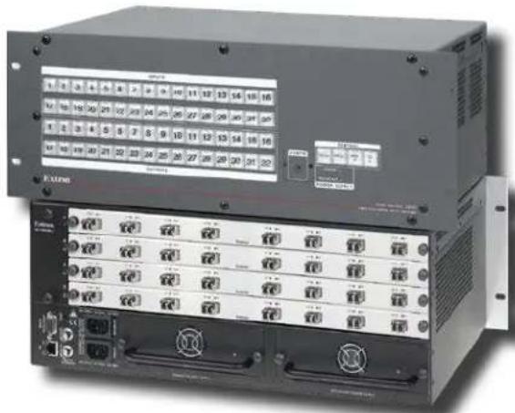
natural_image
Front view of a black industrial rack-mounted server unit with multiple ports and indicator lights (no visible text or labels)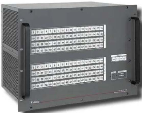
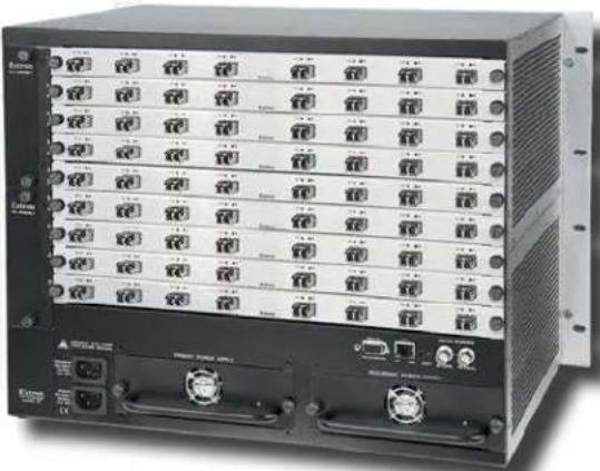
natural_image
Front view of a rack-mounted network equipment unit with multiple ports and connectors (no visible text or labels)Safety Instructions
Safety Instructions • English

WARNING: This symbol, ⚠️, when used on the product, is intended to alert the user of the presence of uninsulated dangerous voltage within the product's enclosure that may present a risk of electric shock.
ATTENTION: This symbol, , when used on the product, is intended to alert the user of important operating and maintenance (servicing) instructions in the literature provided with the equipment.
For information on safety guidelines, regulatory compliances, EMI/EMF compatibility, accessibility, and related topics, see the Extron Safety and Regulatory Compliance Guide, part number 68-290-01, on the Extron website, www.extron.com.
© 2014-2019 Extron Electronics. All rights reserved. www.extron.com
Trademarks
All trademarks mentioned in this guide are the properties of their respective owners. The following registered trademarks (®), registered service marks (SM), and trademarks (TM) are the property of RGB Systems, Inc. or Extron Electronics (see the current list of trademarks on the Terms of Use page at www.extron.com):
Registered Trademarks®)
| Extron, Cable Cubby, ControlScript, CrossPoint, DTP, eBUS, EDID Manager, EDID Minder, Flat Field, FlexOS, Glitch Free. Global Configurator, Global Scripter, GlobalViewer, Hideaway, HyperLane, IP Intercom, IP Link, Key Minder, LinkLicense, LockIt, MediaLink, MediaPort, NetPA, PlenumVault, PoleVault, PowerCage, PURE3, Quantum, Show Me, SoundField, SpeedMount, SpeedSwitch, StudioStation, System INTEGRATOR, TeamWork, TouchLink, V-Lock, VideoLounge, VN-Matrix, VoiceLift, WallVault, WindoWall, XTP, XTP Systems, and ZipClip |
Registered Service Mark ^(SM) : S3 Service Support Solutions
Trademarks ^TM
| AAP, AFL (Accu-Rate Frame Lock), ADSP (Advanced Digital Sync Processing), Auto-Image, AVEdge, CableCover, CDRS (Class D Ripple Suppression), Codec Connect, DDSP (Digital Display Sync Processing), DMI (Dynamic Motion Interpolation), Driver Configurator, DSP Configurator, DSVP (Digital Sync Validation Processing), eLink, EQIP, Everlast, FastBite, FOX, FOXBOX, IP Intercom HelpDesk, MAAP, MicroDigital, Opti-Torque, PendantConnect, ProDSP, QS-FPC (QuickSwitch Front Panel Controller), Room Agent, Scope-Trigger, ShareLink, SIS, Simple Instruction Set, Skew-Free, SpeedNav, Triple-Action Switching, True4K, VectorTM 4K , WebShare, XTRA, and ZipCaddy |
FCC Class A Notice
This equipment has been tested and found to comply with the limits for a Class A digital device, pursuant to part 15 of the FCC rules. The Class A limits provide reasonable protection against harmful interference when the equipment is operated in a commercial environment. This equipment generates, uses, and can radiate radio frequency energy and, if not installed and used in accordance with the instruction manual, may cause harmful interference to radio communications. Operation of this equipment in a residential area is likely to cause interference. This interference must be corrected at the expense of the user.
NOTE: For more information on safety guidelines, regulatory compliances, EMI/EMF compatibility, accessibility, and related topics, see the "Extron Safety and Regulatory Compliance Guide" on the Extron website.
Battery Notice
This product contains a battery. Do not open the unit to replace the battery. If the battery needs replacing, return the entire unit to Extron (for the correct address, see the Extron Warranty section on the last page of this guide).
CAUTION: Risk of explosion. Do not replace the battery with an incorrect type. Dispose of used batteries according to the instructions.
Class 1 Laser Product
Any service to this product must be carried out by Extron Electronics and its qualified service personnel.
CAUTION: Using controls, making adjustments, or performing procedures in a manner other than what is specified herein may result in hazardous radiation exposure.
NOTE: For more information on safety guidelines, regulatory compliances, EMI/EMF compatibility, accessibility, and related topics, see the “Extron Safety and Regulatory Compliance Guide” on the Extron website.
Conventions Used in this Guide
Notifications
The following notifications are used:

WARNING: Potential risk of severe injury or death.
CAUTION: Risk of minor personal injury.
NOTE: A note draws attention to important information.
TIP: A tip provides a suggestion to make working with the application easier.
Software Commands
Commands are written in the fonts shown here:
^AR Merge Scene,,Op1 scene 1,1 ^B51 ^W^C
[01] R000400300004000080000600 [02] 35 [17] [03]
Esc X13 *X18 *X26 *X29 *X27 CE
NOTE: For commands and examples of computer or device responses mentioned in this guide, the character “∅” is used for the number zero and “0” represents the capital letter “o.”
Computer responses and directory paths that do not have variables are written in the font shown here:
Reply from 208.132.180.48: bytes=32 times=2ms TTL=32
C:\Program Files\Extron
Variables are written in slanted form as shown here:
ping xxx.xxx.xxx.xxx-t
SOH R Data STX Command ETB ETX
Selectable items, such as menu names, menu options, buttons, tabs, and field names are written in the font shown here:
From the File menu, select New.
Click the OK button.
Specifications Availability
Product specification are available on the Extron website, www.extron.com.
Extron Glossary of Terms
A glossary of terms is available at http://www.extron.com/technology/glossary.aspx.
Contents
Introduction.... 1
About this Guide....1
About the FOX Matrix Switchers....1
Fiber Cable Transmission Modes 4
Features 4
Installation....7
Setup and Installation Checklist....7
Get Ready 7
Configure the Matrix Switcher....7
Perform Physical Installation 7
Ancillary Operations....7
Rear Panel Boards, Cabling, and Features......8
I/O Boards....10
Remote Port 13
Ethernet Connection....13
Reset Button and LED....14
Switch Reference Connections 15
Power Supply Modules and Indicator LEDs 16
Cooling Fan Assemblies.... 16
Front Panel Configuration Port......17
Operation....18
Front Panel Controls and Indicators....18
Input and Output Buttons 20
Control Buttons 22
Power Indicators....23
Button Icons....24
Rear Panel Power Indicators....24
Front Panel Operations....25
Definitions....25
Power....26
Creating a Configuration 26
Viewing the Configuration 31
I/O Grouping....33
Using Presets 37
Muting and Unmuting Outputs....39
Locking the Front Panel (Executive Mode)..... 41
Performing a System Reset from the Front Panel....41
Background Illumination.... 42
Selecting the Rear Panel Remote Port Protocol and Baud Rate 42
Reset Operations....43
Performing Soft System Resets (Resets 3, 4, and 5) .... 45
Performing a Hard Reset (Reset 1)....46
Troubleshooting....46
Configuration Worksheets.... 47
Worksheet Example 1: System equipment....47
Worksheet Example 2: Daily Configuration....48
Worksheet Example 3: Test configuration ..... 49
Programming Guide....52
Serial Ports....53
Ethernet (LAN) Port 54
Default IP addresses....54
Establishing a Connection.... 54
Connection Timeouts 55
Number of Connections....55
Using Verbose Mode 55
Host-to-Switcher Instructions 55
Switcher-initiated Messages 56
Switcher Error Responses 57
Using the Command and Response Tables ..... 57
Command and Response Table for SIS Commands 58
Command and Response Table for IP- and SNMP-Specific SIS Commands....67
Special Characters 70
Matrix Software....71
Matrix Switchers Control Program 71
Software Operation via Ethernet 71
Software Operation via a Serial Port....72
Installing the Software....72
Using the Matrix Switcher Control Software....75
Updating the Firmware 82
Uploading HTML Files....86
Windows Buttons, List Boxes, and Trash Can....87
Using Emulation Mode....91
Using the Help System 92
Button Label Generator Program....93
Installing the Button Label Generator Software....93
Using the Button Label Generator Software....94
HTML Operation 95
Opening the Embedded Web Pages......96
Status Tab 97
System Status Page 97
Input Link page....98
Configuration Tab 99
System Settings Page 99
Passwords Page.... 102
Email Settings Page....103
SNMP Settings Page 105
Firmware Upgrade Page 107
File Management Tab 108
File Management Page 108
Control Tab....109
Set and View Ties Page....109
Maintenance and Modifications .... 111
Mounting the Switcher....111
UL Guidelines 111
Mounting Instructions 112
Battery and Power Precautions 112
Removing and Installing an I/O Board or Blank Panel 112
Removing an I/O Board or Blank Panel......114
Installing an I/O board or blank panel......114
Removing and Installing a Power Supply Module....115
Removing the Power Supply Module ..... 115
Installing a Power Supply Module 115
Removing and Installing a Fan Module......116
Removing a Fan Module....116
Installing a Fan Module 116
Removing and Installing Button Labels ...... 117
Installing Labels in the Buttons....117
Ethernet Connection 119
Ethernet Link....119
Ethernet Connection....119
Default IP Address....119
Pinging to Determine the Extron IP Address....120
Pinging to Determine the Web IP Address....120
Configuring the Switcher for Network Use via the ARP Command.... 121
Connecting as a Telnet Client....122
Telnet Tips 122
Subnetting — A Primer....124
Gateways 124
Local and Remote Devices 124
IP Addresses and Octets 124
Subnet Masks and Octets 124
Determining Whether Devices Are on the Same Subnet....125
Introduction
WARNING: The FOX matrix switcher outputs continuous invisible light (Class 1 rated), which may be harmful to the eyes; use with caution.
- Do not look into the rear panel fiber optic cable connectors or into the fiber optic cables themselves.
- Plug the attached dust cap into the optical transceiver when the fiber optic cable is unplugged.
This guide contains installation, configuration, and operating information for the Extron FOX Matrix 3200 Switcher and FOX Matrix 7200 Switcher. These customizable matrix switchers support up to 32 (FOX Matrix 3200) or 72 (FOX Matrix 7200) inputs and outputs.
NOTE: In this guide, "FOX matrix switcher" and "switcher" refer to either switcher model unless otherwise specified.
About the FOX Matrix Switchers
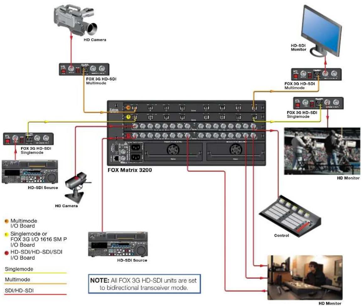
The FOX matrix switchers (see figure 1 on the next page) distribute optical and electronic input signals to one or more optical and electronic outputs. The matrix switchers can route multiple input/output configurations simultaneously. The switchers are configurable, assembled from individual input/output (I/O) boards, each of which supports 8 inputs by 8 outputs in a combination of the following types of board:
- Singlemode and multimode fiber optic I/O 88 reclocking boards — These boards route signals that are compatible with all Extron FOX 500, FOXBOX, FOX II, and PowerCage FOX fiber optic product lines. The boards are not pathologically-compliant.
FOX 3G I/O 88 SM P board — This pathologically-compliant fiber optic board passes digital signals in broadcasting applications, while addressing the compatibility issues of passing pathological signals generated from 3G-SDI, HD-SDI, and SDI signals over fiber optic systems, including those defined by RP 178 and RP 198. - BNC 3G/HD/SD-SDI 88 I/O board — This pathologically-compliant board supports and passes 3G-SDI, HD-SDI, and SD-SDI signals in their native (electronic) format.
flowchart
graph TD
    A["HD Camera"] --> B["FOX 3G HD-SDI Multimode"]
    C["HD-SDI Monitor"] --> D["FOX 3G HD-SDI Singlemode"]
    B --> E["FOX Matrix 3200"]
    D --> E
    E --> F["HD-SDI Source"]
    E --> G["HD-SDI Multi-mode"]
    H["Multimode I/O Board"] --> E
    I["Singlemode or FOX 3G I/O 1616 SM P I/O Board"] --> E
    J["HD-SDI/HD-SDI/SDI I/O Board"] --> E
    K["Singlemode"] --> E
    L["Multimode"] --> E
    M["SDI/HD-SDI"] --> E
    N["HD Monitor"] --> E
    O["Control"] --> E
    P["HD-SDI Source"] --> E
    Q["HD-SDI Multi-mode"] --> E
    R["FOX 3G HD-SDI Singlemode"] --> E
    S["FOX 3G HD-SDI Multimode"] --> E
    T["HD-SDI Monitor"] --> U["FOX 3G HD-SDI Singlemode"]
    V["HD-SDI Source"] --> W["FOX 3G HD-SDI Singlemode"]
    X["HD-SDI Multi-mode"] --> Y["FOX 3G HD-SDI Multimode"]
    Z["HD-SDI Monitor"] --> AA["FOX 3G HD-SDI Singlemode"]
    AB["HD-SDI Source"] --> AC["FOX 3G HD-SDI Multimode"]
    AD["HD-SDI Multi-mode"] --> AE["FOX 3G HD-SDI Multimode"]
    AF["HD-SDI Monitor"] --> AG["FOX 3G HD-SDI Singlemode"]
    AH["HD-SDI Source"] --> AI["FOX 3G HD-SDI Multimode"]
    AJ["HD-SDI Multi-mode"] --> AK["FOX 3G HD-SDI Multimode"]
    AL["HD-SDI Monitor"] --> AM["FOX 3G HD-SDI Singlemode"]
    AN["HD-SDI Source"] --> AO["FOX 3G HD-SDI Multimode"]
    AP["HD-SDI Multi-mode"] --> AQ["FOX 3G HD-SDI Multimode"]
    AR["HD-SDI Monitor"] --> AS["FOX 3G HD-SDI Singlemode"]
    AT["HD-SDI Source"] --> AU["FOX 3G HD-SDI Multimode"]
    AV["HD-SDI Multi-mode"] --> AW["FOX 3G HD-SDI Multimode"]
    AX["HD-SDI Monitor"] --> AY["FOX 3G HD-SDI Singlemode"]
    AZ["HD-SDI Source"] --> BA["FOX 3G HD-SDI Multimode"]
    BB["HD-SDI Multi-mode"] --> BC["FOX 3G HD-SDI Multimode"]
    BD["HD-SDI Monitor"] --> BE["FOX 3G HD-SDI Singlemode"]
    BF["HD-SDI Source"] --> BG["FOX 3G HD-SDI Multimode"]
    BH["HD-SDI Multi-mode"] --> BI["FOX 3G HD-SDI Multimode"]
    BJ["HD-SDI Monitor"] --> BK["FOX 3G HD-SDI Singlemode"]
    BL["HD-SDI Source"] --> BM["FOX 3G HD-SDI Multimode"]
    BN["HD-SDI Multi-mode"] --> BO["FOX 3G HD-SDI Multimode"]
    BP["HD-SDI Monitor"] --> BQ["FOX 3G HD-SDI Singlemode"]
    BR["HD-SDI Source"] --> BS["FOX 3G HD-SDI Multimode"]
    BT["HD-SDI Multi-mode"] --> BU["FOX 3G HD-SDI Multimode"]
    BV["HD-SDI Monitor"] --> BW["FOX 3G HD-SDI Singlemode"]
    BX["HD-SDI Source"] --> BY["FOX 3G HD-SDI Multimode"]
    BZ["HD-SDI Multi-mode"] --> CA["FOX 3G HD-SDI Multimode"]
    CB["HD-SDI Monitor"] --> CC["FOX 3G HD-SDI Singlemode"]
    CD["HD-SDI Source"] --> CE["FOX 3G HD-SDI Multimode"]
    CF["HD-SDI Multi-mode"] --> CG["FOX 3G HD-SDI Multimode"]
    CH["HD-SDI Monitor"] --> CI["FOX 3G HD-SDI Singlemode"]
    CJ["HD-SDI Source"] --> CK["FOX 3G HD-SDI Multimode"]
    CL["HD-SDI Multi-mode"] --> CM["FOX 3G HD-SDI Multimode"]
    CN["HD-SDI Monitor"] --> CO["FOX 3G HD-SDI Singlemode"]
Figure 1. Typical FOX Matrix 3200 Application
NOTE: The non-pathologically-compliant multimode and singlemode fiber optic I/O boards are physically and functionally identical, with the exception of the effective range of transmission. In this guide, any reference to fiber optic transmission applies to either transmission mode unless otherwise specified. The pathologically-compliant fiber optic I/O board is identified separately where appropriate.
By adding or removing I/O boards, the FOX matrix switcher is expandable and contractable within the following ranges:
- FOX Matrix 3200 — Includes up to four I/O boards. It is expandable from an 8-input by 8-output matrix to a 32-input by 32-output matrix.
- FOX Matrix 7200 — Includes up to nine I/O boards. It is expandable from an 8-input by 8-output matrix to a 72-input by 72-output matrix.
The Extron proprietary fiber optic signal, generated by FOX 500, FOXBOX, PowerCage FOX, and FOX II transmitters, can include video, stereo audio, and transmitter-to-receiver RS-232 serial communications. The video component of the signal can be of a variety of formats, depending on the transmitter and receiver:
RGB video
• 3G-SDI, HD-SDI, or SDI video
• Digital Visual Interface (DVI) video
• Low resolution (composite video or S-video)
NOTES:
- Compatible optical signals are digital signals from 270 Mbs through 4.25 Gbps, sent and received via fiber optic small form factor pluggable (SFP) modules. The FOX matrix switchers support all compatible optical signals, whether transmitted or received by an Extron FOX system component or not.
- The Extron FOX 500, FOXBOX, and PowerCage FOX transmitter-to-receiver communications, including the serial link, occupy one matrix switcher input and output. This matrix switcher also supports the Extron FOX return (receiver-to-transmitter) serial communications, but returning this signal stream to the transmitter uses a separate matrix switcher input and output.
The switchers input and output the optical signals that they route on fiber optic transceiver modules and the 3G-SDI, HD-SDI, and SDI video signals on BNC connectors.
The switcher has two 100 VAC to 240 VAC, 50-60 Hz, 175-watt power supplies that provide worldwide power compatibility and reliability.
The matrix switcher is a single box solution to complex fiber optic and broadcast signal routing applications. Each input and output is individually isolated and buffered. Any input can be switched to any one output or all outputs with virtually no crosstalk or signal noise between channels.
The matrix switcher can be remotely controlled using either the Extron Matrix Switchers Control Program or the Simple Instruction Set (SIS). Control is available via:
• A rear panel Remote RS-232/RS-422 port
• A rear panel LAN port
• A front panel RS-232 serial Config (configuration) port
The SIS is a set of basic ASCII code commands that provide simple control through a control system or PC without the need to enter long strings of code. SIS commands can be entered via any of the ports listed above.
The switcher can be operated remotely by any of the following connected to a serial port or LAN port:
- A control system
A PC computer
• An Extron MKP 2000 or remote control panel
• An Extron MKP 3000 remote control panel
- (RS-232 or RS-422 only) An Extron MCP 1000 remote control panel, an MKP 1000 remote keypad, or both
The matrix switcher is housed in a rack-mountable, metal enclosure with mounting flanges for standard 19-inch racks. The sizes are as follows:
• FOX Matrix 7200 — 8U high
• FOX Matrix 3200 — 4U high
Fiber Cable Transmission Modes
Two versions of non-pathologically-compliant FOX matrix switcher fiber optic I/O board are documented in this guide. They are categorized by the type of fiber optic cable, multimode or singlemode, which defines the effective range of transmission:
- Multimode — Long distance, up to 300 m (985 feet)
- Singlemode — Very long distance, up to 30 km (18.75 miles)
NOTES:
- All transceiver modules on a fiber optic I/O board, as delivered from Extron, are configured the same; either all multimode or all singlemode.
- You can mix multimode and singlemode fiber optic I/O boards in a FOX matrix switcher, but you must ensure that you connect the proper transmission mode fiber cables to the board.
Features
Fiber optic inputs and outputs — With fiber optic I/O boards, the switchers input and output fiber optic signals on SFP optical connectors. The fiber optic I/O boards support digital signals from 270 Mbs through 4.25 Gbps.
3G-SDI, HD-SDI, or SDI inputs and outputs — With 3G/HD/SD-SDI I/O boards, the switchers input and output SDI and HD-SDI signals on BNC connectors. The 3G/HD/SD-SDI I/O boards support multi-rate SDI at rates up to 2.97 Gbps, and comply with SMPTE 259M-C, 292M, 424M, and ITU digital video standards.
Cross-format compatibility —
- An input on an 3G/HD/SD-SDI I/O board can be tied to an output on a fiber optic I/O board or another 3G/HD/SD-SDI I/O board.
- An input on a fiber optic I/O board can be tied to an output on an 3G/HD/SD-SDI I/O board or another fiber optic I/O board.
Switching flexibility — The switcher provides individually buffered, independent matrix switched outputs.
- Tie any input to any or all outputs.
- Quick multiple tie — Multiple inputs can be switched to multiple outputs simultaneously. This allows all displays (outputs) to change from source to source at the same time.
Input link detection — In critical environments or unmanned, remote locations, it may be vital to know that sources are active and switching. The switcher confirms that input sources are active by detecting light. Link detection provides instantaneous feedback via the serial ports or LAN port of the switcher. The input information can be displayed on any control system or in a Windows®-based control program on a local-area network (LAN) or Internet (IP) connection.
Rooming — The switcher can be programmed to group multiple outputs to specific "rooms", allowing them to have their own presets.
Operational reliability — The FOX matrix switcher can support round-the-clock operation in mission-critical applications, using a combination of hot-swappable components and redundant power supplies.
- Field upgradable, hot-swappable modular design — You can repair, upgrade, reconfigure, or expand the matrix by simply installing a new I/O board or replacing a board of one type with one of another. Hot-swappable components let you replace any I/O board at any time without powering down the switcher.
- Power redundancy — The built-in redundancy ensures zero downtime and no loss of functionality through all but catastrophic power failure.
- Two AC power inputs — The switcher can remain powered through any power interruption short of a simultaneous loss of power on both power sources.
- Primary and redundant, hot-swappable power supplies — The hot-swappable, externally mounted redundant power supply is configured to automatically take over the load from the primary supply in the case of a failure.
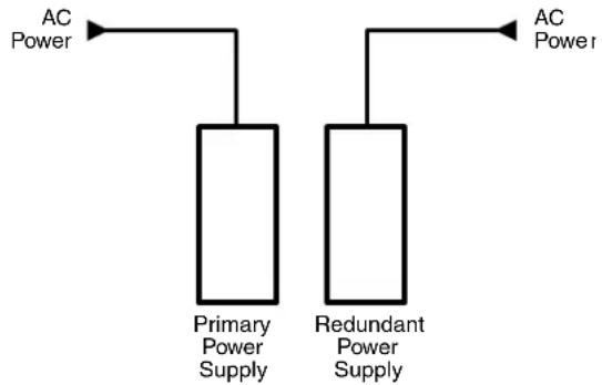
The complete power circuit, from the plug, through the power supply, to the insertion of the power onto the power distribution plane, is separate and redundant (see figure 2). If the installation includes uninterruptible or completely separate power sources, the switcher remains powered up through any power interruption except a simultaneous loss of power on both power sources.
flowchart
graph TD
    A["AC Power"] --> B["Primary Power Supply"]
    C["AC Power"] --> D["Redundant Power Supply"]
Figure 2. Redundant Power Supply Backs up Primary
The hot-swappable redundant power supply means no downtime for the switcher and no loss of functionality should one power supply fail. Should a primary power supply fail, the redundant power supply immediately assumes the load of the failed primary supply. A failed power supply is easily replaceable from the rear at any time without powering down the matrix and with no tools required.
- Ease of maintenance — A failed power supply can be easily replaceable from the rear at any time without powering down the matrix, and with no tools required.
- Power supply status LEDs — Front panel and rear panel LEDs indicate the status of the primary and redundant power supplies.
- Hot-swappable fans — The hot-swappable, externally mounted fans allow quick replacement to avert overheating in the case of a failure. Fans can be replaced without powering down the switcher.
- Operational flexibility — Operations such as input/output selection and setting of presets can be performed using a variety of local and remote control mechanisms:
- Front panel controller
• Windows-based Matrix Switchers Control Program
• Simple Instruction Set (SIS) - Remote control panels and keypads
SNMP support for remote monitoring — Supports the Simple Network Management Protocol (SNMP) internet-standard protocol, allowing IT personnel to manage devices on the IP network.
Laser controls — Non-pathologically-compliant fiber optic boards can be set, via SIS commands, to individually or globally disable the output laser drivers so that a driver does not output light. They can also be set, individually or globally, to automatic so that a driver turns on when a tie is made involving that driver or turns off when no tie is made.
Upgradeable firmware — The firmware that controls all switcher operation can be upgraded in the field via either serial port or the Ethernet port, without taking the switcher out of service. Firmware upgrades are available for download at www.extron.com, and can be installed using the Windows-based control program or the built-in HTML pages.
Labeling — The Button Label Generator software, available at www.extron.com, lets you create labels to place in the front panel I/O buttons, with names, alphanumeric characters, or color bitmaps for easy and intuitive input and output selection.
Global memory presets — 32 (FOX Matrix 3200) or 64 (FOX Matrix 7200) global memory presets are a time-saving feature that lets you set up and store input/output configurations in advance. You can then recall those configurations, when needed, with a few simple steps. The presets are available via front panel operation or serial port or Ethernet control.
Rack mounting — Rack mountable in any conventional 19-inch wide rack.
Front panel security lockout modes (Executive mode) — If a matrix switcher is installed in an open area, where operation by unauthorized personnel may be a problem, a security lockout mode can be implemented. When the front panel is locked, a special button combination or SIS command is required to unlock the front panel controller and make the front panel fully operational.
I/O grouping — Allows the matrix to be virtually divided into smaller subswitchers, making installation and control easier. I/O grouping limits the selection of inputs and outputs to members of the same group. I/O grouping allows specific outputs, such as those designated for a specific purpose, to be grouped together.
Video genlock (SDI / HD-SDI inputs only) — Allows for vertical interval switching and enables smooth, seamless transitions when switching between synchronous video sources. Separate bi-level (SDI) and tri-level (HD-SDI) references are provided on two separate BNC connectors.
Permanent, rechargeable battery — The matrix switcher has a rechargeable lithium battery to track time of day when power is disconnected.

WARNING: There is a danger of explosion if the battery is incorrectly replaced.
Replace it only with the same or equivalent type recommended by the manufacturer. Dispose of used batteries according to the instructions of the manufacturer.
This section details the installation and configuration of the FOX matrix switchers, including:
- Setup and Installation Checklist
- Rear Panel Boards, Cabling, and Features
- Front Panel Configuration Port
Setup and Installation Checklist
Get Ready
☐ Familiarize yourself with the FOX matrix switcher.
☐ Obtain IP setting information for the matrix switcher from the local network administrator. Read the Ethernet Connection section, beginning on page 119.
Configure the Matrix Switcher
☐ Install the desired I/O boards (page 112).
Perform Physical Installation
☐ If desired, install the switcher in a rack (see Mounting the Switcher on page 111).
☐ If desired, create (page 94) and replace (page 117) button labels.
☐ Cable input and output devices to the I/O bolar(page 11).
☐ If deair, connect computers or control systems to any of the remote control ports on the switcher (two serial ports [page 13 and page 17] and a LAN port [page 13]).
□ Connect power (page 16).
☐ Test the switcher by creating a tie (page 27).
Ancillary Operations
☐ Install the Matrix Switchers Control Program (page 72).
Rear Panel Boards, Cabling, and Features
NOTE: Figure 3 shows a FOX Matrix 3200. Figure 4, on the next page, shows a FOX Matrix 7200. The two models have similar features, but are in different-sized enclosures and the features are arranged differently. The FOX Matrix 7200 has two fan assemblies.
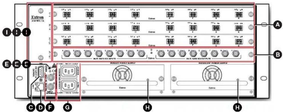
Figure 3. FOX Matrix 3200 Fiber Optic Matrix Switcher Rear Panel
ATTENTION:
A Fiber optic boards with connectors and LEDs (see page 11)
B 3G-SDI, HD-SDI, and SDI boards with connectors and LEDs (see page 12)
© Remote RS-232 / RS-422 port (see page 13)
D Ethernet connection (LAN connector) (see page 13)
E Reset button (see page 14)
F Switch Reference connectors (see page 15)
G Power connectors (see page 16)
H Power supply modules and indicator LEDs (see page 16)
Cooling fan assembly (see Removing and Installing a Fan Module on page 116)
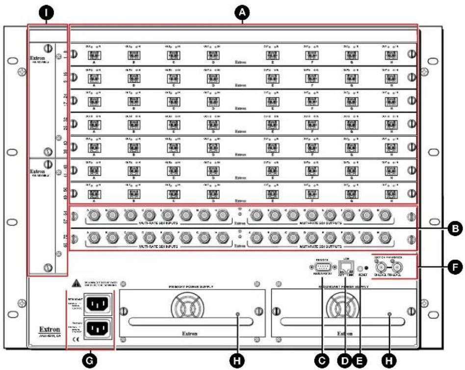
Figure 4. FOX Matrix 7200 Fiber Optic Matrix Switcher Rear Panel
A Fiber optic boards with connectors and LEDs (see page 11)
B 3G-SDI, HD-SDI, and SDI boards with connectors and LEDs (see page 12)
© Remote RS-232 / RS-422 port (see page 13)
D Ethernet connection (LAN connector) (see page 13)
E Reset button (see page 14)
F Switch Reference connectors (see page 15)
G Power connectors (see page 16)
H Power supply modules and indicator LEDs (see page 16)
Cooling fan assembly (see Removing and Installing a Fan Module on page 116)
I/O Boards
As shown in figure 5, each I/O board is identified by the input and output numbers supported by the board position, which are printed on the side of each fan module (1 - 8, 9 - 16, and so on). The transceiver modules on fiber optic I/O boards are identified as A through H.
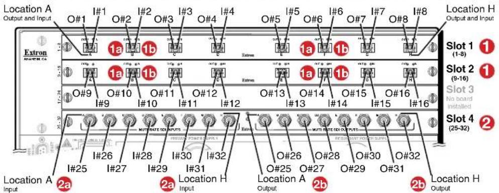
Figure 5. Arrangement of Inputs and Outputs on the I/O Boards
NOTE: On the fiber optic I/O boards, the output on the transceiver module is to the left of the input.
| Slot Inputs and Outputs Slot Inputs and Outputs | ||
| 1 1 through 8 5* 33 through 40 | ||
| 2 9 through 16 6* 41 through 48 | ||
| 3 17 through 24 7* 49 through 56 | ||
| 4 25 through 32 8* 57 through 64 | ||
| 9* 65 through 72 | ||
* FOX Matrix 7200 only
Locations A through H correspond to the input and output numbers identified by the board position numbers. For example, the input and output numbers supported by the I/O board in location 9 - 16 (slot 2) are as follows: A = 9, B = 10, C = 11, D = 12, E = 13, F = 14, G = 15, and H = 16.
On the fiber optic I/O boards (1), locations A through H correspond to the transceiver modules, each of which includes an input (1a) and an output (1b). Therefore, locations A through H are numbered from left to right.
On the 3G/SDI/HD-SDI I/O boards (2), inputs (2a) and outputs (2b) are grouped separately, with inputs A through H on the left and outputs A through H on the right.
Fiber optic boards

flowchart
graph LR
    A["Port A"] -->|2a| B["Port B"]
    B -->|2a| C["Port C"]
    C -->|2a| D["Port D"]
    D -->|2a| E["Port E"]
    E -->|2a| F["Port F"]
    F -->|2a| G["Port G"]
    G -->|2a| H["Port H"]
    style A fill:#f9f,stroke:#333
    style B fill:#f9f,stroke:#333
    style C fill:#f9f,stroke:#333
    style D fill:#f9f,stroke:#333
    style E fill:#f9f,stroke:#333
    style F fill:#f9f,stroke:#333
    style G fill:#f9f,stroke:#333
    style H fill:#f9f,stroke:#333
Figure 6. Fiber Optic Board
A Fiber optic board, connectors (see figure 3 on page 8 and figure 4 on page 9) —

WARNING: The FOX matrix switchers fiber optic I/O boards output continuous invisible light (Class 1 rated), which may be harmful to the eyes; use with caution. Plug the attached dust cap into the optical transceiver when the fiber optic cable is unplugged.
- Ensure that you use the proper fiber cable for your I/O board. Typically, singlemode fiber has a yellow jacket and multimode cable has an orange or aqua jacket.
- Unlike most Extron transmitters and receivers, which output an optical stream on one connector in a block and receive a return optical stream on the second connector in the same block, the FOX matrix switchers use one connector on the block as an input and the second connector on the same block as a separate output.
- All transceiver modules on a fiber optic I/O board, as delivered from Extron, are configured the same: either all multimode or all singlemode.
- You can mix multimode and singlemode fiber optic I/O boards in a FOX matrix switcher, but you must ensure that you connect the proper transmission mode fiber cables to the board.
1a Input connector and LED — For all one-way video, audio, and serial communications output by a transmitter, connect a fiber optic cable to the Input LC connector (see figure 7).
Connect the free end of this fiber optic cable to the Optical Tx LC connector on a FOXBOX Tx transmitter or to any other compatible fiber optic device.
NOTES:
- For a FOX 500 transmitter, connect this fiber optic cable to the Optical 1 LC connector.
• Alternatively, for the serial return (receiver-to-transmitter) function, connect the far end of the cable to the Optical 2 connector on a receiver.
Input LED — See Fiber optic I/O board LED indications on the next page.
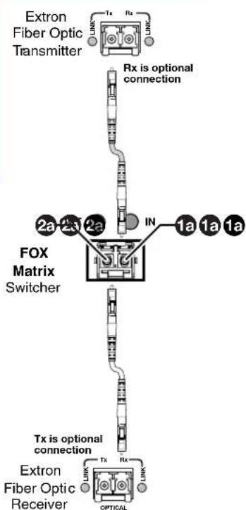
Figure 7. Optical Connections
2a Output connector — For all one-way video, audio, and serial communications output to a receiver, connect a fiber optic cable to the Output LC connector (see figure 7, on the previous page).
Connect the far end of this fiber optic cable to the Optical Rx connector on a FOXBOX Rx receiver or to any other compatible fiber optic device.
NOTES:
- For a FOX 500 receiver, connect this fiber optic cable to the Optical 1 LC connector.
- Alternatively, for the serial return (receiver-to-transmitter) function, connect the far end to the Optical RX or Optical 2 connector on a transmitter.
Output LED — See "Fiber optic I/O board LED indications" below.
Fiber optic I/O board LED indications
On the fiber optic I/O boards, the input and output LEDs on the transceivers provide useful indications of the status of the lasers and the reclocking function (see the table below).
| Definition | Output LED indication | Input LED indication Definition |
| Reclocked at 4.25 Gbps On | On Reclocked at | 4.25 Gbps |
| Not reclocked, laser off, or no signal | Off Off Not | reclocked or no signal |
| Non-4G signal present or not reclocked | Fast blink Fast | blink Non-4G signal present or not reclocked |
NOTE: If the reclocking feature is bypassed (see the Set output reclocker SIS command on page 60), the output LED is always on.
3G/HD/SD-SDI boards

Figure 8. 3G/HD/SD-SDI Board
B BNC board with connectors (see figure 3 on page 8 and figure 4 on page 9) —
15 Multi-rate SDI Input connectors — Connect 3G-SDI, HD-SDI, SDI or video inputs to these BNC connectors.
2b Multi-rate SDI Output connectors — Connect digital displays to these BNC connectors.
Remote Port
Remote RS-232/RS-422 connector (see figure 3 on page 8 and figure 4 on page 9) — Connect a host device, such as a computer or touchpanel control, to the switcher via this 9-pin D connector for serial RS-232 or RS-422 control (see figure 9).
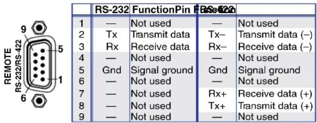
See Programming Guide on page 52 for definitions of the SIS commands (serial commands to control the switcher via this connector) and Matrix Software on page 71 for details on how to install and use the control software.
NOTE: The switcher can support either the RS-232 or the RS-422 serial communication protocol, and can operate at 9600, 19200, 38400, or 115200 baud rates.
See the Command and Response Table for IP- and SNMP-Specific SIS Commands on page 68 to configure this port under SIS control.
If desired, connect an MKP 2000 or MKP 3000 remote control panel to the Remote RS-232/RS-422 connector. See the MKP 2000 Remote Control Panel User Guide or the MKP 3000 User Guide for details.
Ethernet Connection
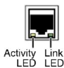
D LAN port (see figure 3 and figure 4) — For IP control of the system, connect the matrix switcher to a PC or to an Ethernet LAN via this RJ-45 connector. You can use a PC to control the networked switcher with SIS commands from anywhere in the world. You can also control the switcher from a PC that is running the Extron Matrix Switchers Control Program or has downloaded HTML pages from the switcher.
Link LED indicator — The green (link) LED indicates that the switcher is properly connected to an Ethernet LAN. This LED should light steadily.
Act LED indicator — The yellow (activity) LED indicates transmission of data packets on the RJ-45 connector. This LED should flicker as the switcher communicates.
Cabling
It is vital that your Ethernet cables be the correct cable type and that they be properly terminated with the correct pinout. Ethernet links use Category (CAT) 3, 5e, or CAT 6, unshielded twisted pair (UTP) or shielded twisted pair (STP) cables, terminated with RJ-45 connectors. Ethernet cables are limited to a length of 328 feet (100 meters).
NOTES:
- Do not use standard telephone cables. Telephone cables do not support Ethernet or Fast Ethernet.
- Do not stretch or bend cables. Transmission errors can occur.
The cable used depends on your network speed. The switcher supports both 10 Mbps (10Base-T — Ethernet) and 100 Mbps (100Base-T — Fast Ethernet), half-duplex and full-duplex Ethernet connections.
- 10Base-T Ethernet requires CAT 3 UTP or STP cable at minimum.
- 100Base-T Fast Ethernet requires CAT 5e UTP or STP cable at minimum.
RJ-45 connector wiring
The Ethernet cable can be terminated as a straight-through cable or a crossover cable and must be properly terminated for your application (see figure 10).
- Crossover cable — Direct connection between the computer and the FOX matrix switcher
- Patch (straight) cable — Connection of the FOX matrix switcher to an Ethernet LAN
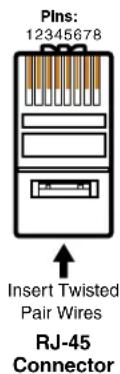
| Pin | End 1 End 2 Wire color | End 1 End 2 Wire color |
| 1 | White-green | White-orange |
| 2 | Green | Orange |
| 3 | White-orange | White-green |
| 4 | Blue | Blue |
| 5 | White-blue | White-blue |
| 6 | Orange | Green |
| 7 | White-brown | White-brown |
| 8 | Brown | Brown |
T568A T568B A cable that is wired as T568A at one end and T568B at the other (Tx and Rx pairs reversed) is a "crossover" cable.
| Pin | Wire color | Wire color |
| 1 | White-orange | White-orange |
| 2 | OrangeOrange | |
| 3 | White-green | White-green |
| 4 | Blue | Blue |
| 5 | White-blue | White-blue |
| 6 | GreenGreen | |
| 7 | White-brown | White-brown |
| 8 | Brown | Brown |
A cable that is wired the same at both ends is called a "straight-through" cable, because no pin/pair assignments are swapped.
Figure 10. RJ-45 Connector and Pinout Tables
Reset Button and LED
E Reset button (see figure 3 on page 8 and figure 4 on page 9) —

The recessed Reset button initiates four levels of matrix switcher reset. For four different reset levels, press and hold the button while the switcher is running or while you power up the switcher (see Reset Operations on page 43 for details).
- Hard (mode 1) reset — Restore the switcher to the default factory conditions and return the switcher to the default firmware that shipped with the unit.
- Events (mode 3) reset — Toggles events monitoring on and off.
• IP settings (mode 4) reset — Reset the IP functions of the switcher.
NOTE: The IP settings reset does not replace any user-installed firmware.
- Absolute (mode 5) reset — Restore the switcher to the default factory conditions.
NOTES:
• Factory loaded firmware is active until it is replaced or the power is cycled.
- Hard reset does not clear the current configuration.
Switch Reference Connections
F Switch Reference connectors for bi-level and tri-level sync (see figure 3 on page 8 and figure 4 on page 9) — (3G, HD-SDI, and SDI inputs and outputs only) Connect an external sync signal to this BNC connector to genlock the video signal in broadcast or other sync-critical applications.
The switcher makes ties to inputs on 3G/SDI/HD-SDI I/O boards during the vertical interval period of the tied video, resulting in glitch-free video switching when the input devices are also using the same sync timing. The FOX matrix switcher can use an external signal to synchronize switching during the vertical interval. Without this external sync locking feature, switching between inputs could result in brief video or picture rolling (sync loss) or a brief change in the picture size.
Figure 11 shows a basic external sync configuration. The Bi-level or Tri-level sync connector receives the timing signal. A tee connector attached to the cable allows the signal to be passed on to another video device, if required. Terminate the tee connector if desired.
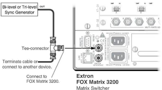
Figure 11. Simple FOX Matrix Switcher External Sync Connection Example
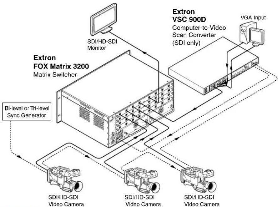
Figure 12 on the next page shows another configuration, in which the timing source passes through three video cameras and a video scan converter before connecting to the switcher. This type of video camera is capable of synchronizing with the external timing source for video editing applications.
NOTE: The Switch Reference connectors are tied into the I/O grouping feature of the switcher:
- Ties to any input in I/O group 1 use the tri-level sync reference.
- Ties to any output in I/O group 2 use the bi-level sync reference.
See I/O grouping on page 33 to assign sync-critical inputs and outputs to the appropriate I/O groups.
If no external sync timing source is connected to the switcher, switching occurs immediately.
flowchart
graph TD
    A["Extron FOX Matrix 3200 Matrix Switcher"] -->|Bi-level or Tri-level Sync Generator| B["SDI/HD-SDI Video Camera"]
    A -->|Bi-level or Tri-level Sync Generator| C["SDI/HD-SDI Video Camera"]
    A -->|Bi-level or Tri-level Sync Generator| D["SDI/HD-SDI Video Camera"]
    A -->|Bi-level or Tri-level Sync Generator| E["Extron VSC 900D Computer-to-Video Scan Converter (SDI only)"]
    A -->|Bi-level or Tri-level Sync Generator| F["VGA Input"]
    A -->|Bi-level or Tri-level Sync Generator| G["SDI/HD-SDI Monitor"]
    A -->|Bi-level or Tri-level Sync Generator| H["SDI/HD-SDI Monitor"]
Figure 12. Multiple Device Example of a FOX Matrix 3200 External Sync
Power Supply Modules and Indicator LEDs
G Primary and Redundant AC power connectors (see figure 3 on page 8 and figure 4 on page 9) — Plug standard IEC power cords into these connectors to connect the switcher to 100 VAC to 240 VAC, 50 or 60 Hz power sources.
NOTE: For the most reliable power, connect the power cord from the Redundant power connector to either an uninterruptible power source or to a power source that is completely independent from the primary power source.
Primary and Redundant power supply indicator LEDs (see figure 3 and figure 4) —
Green — Indicates that the associated power supply is operating within normal tolerances.
Red — Indicates that the associated power supply is operating outside the normal tolerances or has failed. See Removing and Installing a Power Supply Module on page 115 to replace the power supply.
Cooling Fan Assemblies
Primary and Redundant cooling fans (see figure 3 and figure 4) — Cool the equipment. If a fan has failed, replace it at your earliest opportunity. See Removing and Installing a Fan Module on page 116 to replace the fans.
Front Panel Configuration Port
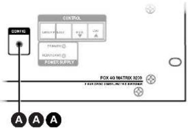
Figure 13. Front Panel Configuration (Config) Port
A Configuration port — This 2.5 mm mini stereo jack serves the same serial communications function as the rear panel Remote port, but it is easier to access than the rear port after the matrix switcher has been installed and cabled. The optional 9-pin D to 2.5 mm mini jack TRS RS-232 cable (see figure 14) can be used for this connection.
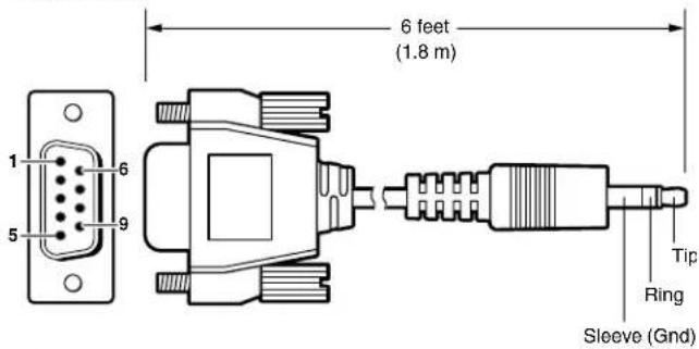
| 9-pin D | Connection | TRS Plug |
| Pin 2 | Rx line on the computer | Tip |
| Pin 3 | Tx line on the computer | Ring |
| Pin 5 | Signal ground on the computer | Sleeve |
Figure 14. Optional 9-pin TRS RS-232 Cable
NOTES:
- This port is independent of the rear panel Remote port and is not affected by changes to the protocol of the rear panel port. The protocol of the front panel port can be changed under SIS command control only. See the Command and Response table for IP- and SNMP-Specific SIS commands on page 68 to configure this port under SIS control.
- A front panel Configuration port connection and a rear panel Remote port connection can both be active at the same time.
- The maximum distance from the matrix switcher to the controlling device can be up to 200 feet (61 meters). Factors such as cable gauge, baud rates, environment, and output levels (from the switcher and the controlling device) all affect transmission distance. Distances of about 50 feet (15 meters) or less are typically not a problem. In some cases the matrix switcher may be capable of serial communications via RS-232 up to 250 feet (76 meters) away.
This port is RS-232 only, with its default protocols as follows:
9600 baud
- no parity
8 data bits
• 1 stop bit
- no flow control
Operation
This section describes the front panel operation of the FOX matrix switcher, including:
• Front Panel Controls and Indicators
- Rear Panel Power Indicators
- Front Panel Operations
- Reset Operations
- Troubleshooting
- Configuration Worksheets
Front Panel Controls and Indicators
The front panel controls (see figure 15, below, and figure 16 on the next page) are grouped into two sets. The input and output buttons are grouped on the left side of the control panel. The control buttons are grouped on the right side of the panel.
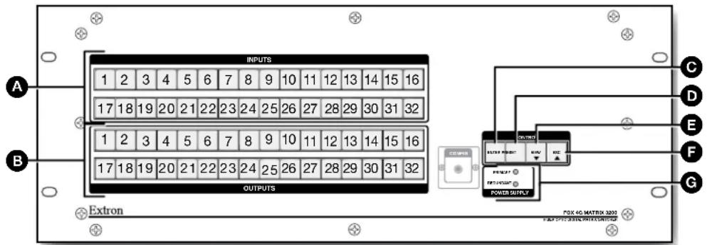
Figure 15. Front Panel, FOX Matrix 3200 Switcher
A Input buttons (see page 20).
B Output buttons (see page 21).
© Enter button (see page 22).
D Preset button (see page 22).
E View button (see page 23).
Esc button (see page 23).
G Primary and Redundant Power Supply LEDs (see page 23).

Figure 16. Front Panel, FOX Matrix 7200 Switcher
The illuminated pushbuttons on both switcher models can be labeled with either text or graphics. The buttons can be set to provide amber background illumination all the time or the background illumination can be turned off (see Background illumination, on page 42). The buttons blink or are lit at full intensity (depending on the operation) when selected.
A Input buttons (see page 20).
B Output buttons (see page 21).
© Enter button (see page 22).
D Preset button (see page 22).
E View button (see page 23).
Esc button (see page 23).
G Primary and Redundant Power Supply LEDs (see page 23).
Input and Output Buttons
NOTE: See Front Panel Operations on page 25 for detailed descriptions of the following operations.
| Primary functions | ||||
| Action Select | input or output for tie being created. | |||
| Indication Blank: potential tie or untie.Lit: current tie | ||||
| FOX Matrix 3200 | 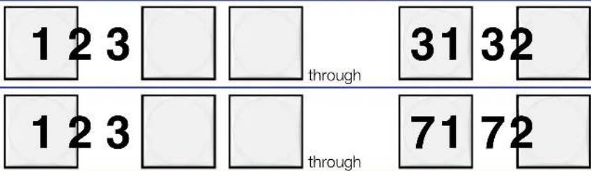 | |||
| FOX Matrix 7200 | ||||
| Secondary functions | ||||
| I/O grouping Action 1 Input 1 | and Output 1:Select I/O Group mode. | |||
| Presets Action | Select a preset in Preset mode. | |||
| Output mutes Action | Output buttons:Press and hold to mute or unmute the output. | |||
| Port configuration Action | Output31 or 71:Select RS-232. | |||
| Blink: selected | ||||
| Background illumination Action | Input 1 and Input 2:Toggle between backgroundillumination or buttons unlit. | |||
A Input buttons — The input buttons have one primary function (☐) and four secondary functions (●):
☐ Select and identify an input.
- (Input 1 only) With the Output 1 button, select I/O Group mode.
- Assign an input to the selected group in I/O Group mode and indicate its assignment.
- Select a preset.
- (Input 1 and Input 2 only) Toggle background illumination of the buttons on and off.
B Output buttons — The output buttons have one primary function (☐) and seven secondary functions (●):
☐ Select and identify an output.
• (Output 1 only) With the Input 1 button, select I/O Group mode.
- Assign an output to the selected group in I/O Group mode and indicate its assignment.
- Select a preset.
- Mute the output.
- Output 31 (FOX Matrix 3200) or Output 71 (FOX Matrix 7200) — Select the RS-232 protocol for the RS-232/RS-422 port in Serial Port Selection and Configuration mode and indicate its selection.
- Output 32 (FOX Matrix 3200) or Output 72 (FOX Matrix 7200) — Select the RS-422 protocol for the RS-232/RS-422 port in Serial Port Selection and Configuration mode and indicate its selection.
Control Buttons
NOTE: See Front Panel Operations on page 25 for detailed descriptions of the following operations.
| Primary functions | |||||
| Action | Save changes | Select Preset mode | Select View mode | Cancel or Escape | |
| Indication | Blink: Save needed | Blink: Save presetLit: Recall preset | View mode selected | flashes once | |
 |  |  |  | ||
| Secondary functions | |||||
| I/O grouping Action/indication | Select and indicate group 1 | Select and indicate group 2 | Select and indicate group 3 | Select and indicate group 4 | |
| Port configuration | Action 1 Select Configuration mode. | ||||
| Action 2 Select 9600 baud Select 19200 baud Select 38400 baud Select 115200 baud | |||||
| Indication | Blink: 9600 baud | Blink: 19200 baud | Blink: 38400 baud | Blink: 115200 baud | |
| Front panel lock | Action With Esc, toggle front panel lock on and off. | With Enter, toggle front panel lock on and off. | |||
| Action | Flash twice to indicated the front panel has been locked or unlocked. | ||||
Enter button — The Enter button has two primary functions (☐) and three secondary functions (●):
☐ Saves configuration or preset changes that you make on the front panel. To create a simple configuration:
- Press the desired input button (item A on page 20).
- Press the desired output button or buttons (item B on page 21).
- Press the Enter button.
☐ Indicates that a potential tie has been created but not saved.
• In the I/O Group mode, selects group 1 and indicates the selection.
- With the Preset, View, and Esc buttons, selects Serial Port Selection and Configuration mode.
- With the Esc button, toggles the front panel lock on and off.
D Preset button — The Preset button has two primary functions (☐) and three secondary functions (●):
☐ Activates Save Preset mode to save a configuration as a preset and Recall Preset mode to activate a previously-defined preset.
☐ Blinks when Save Preset mode is active and lights steadily when Recall Preset mode is active.
• In the I/O Group mode, selects group 2 and indicates the selection.
- With the Enter, View, and Esc buttons, selects Serial Port Selection and Configuration mode.
- Selects 19200 baud for the rear panel Remote port in Serial Port Selection and Configuration mode and indicates the selection.
E View (▼) button — The View (▼) button has one primary function (☐) and three secondary functions (●):
☐ Select and indicate View-only mode, which displays the current configuration.
NOTE: View-only mode also provides a way to mute and unmute the outputs.
• In the I/O Group mode, selects group 3 and indicates the selection.
- With the Enter, Preset, and Esc buttons, selects Serial Port Selection and Configuration mode.
- Selects 38400 baud for the rear panel Remote port in Serial Port Selection and Configuration mode, and indicates the selection.
F Esc (▲) button — The Esc (▲) button has two primary functions (☐) and four secondary functions (●):
☐ Cancels operations or selections in progress and resets the front panel button indicators.
NOTE: The Esc button does not reset the current configuration or any presets.
☐ Flashes once to indicate that the escape function has been activated.
• In the I/O Group mode, selects group 4 and indicates the selection.
- With the Enter, Preset, and View buttons, selects Serial Port Selection and Configuration mode.
- Selects 115200 baud for the rear panel Remote port in Serial Port Selection and Configuration mode and indicates the selection.
- With the Enter button, toggles the front panel lock on or off.
Power Indicators
G Primary and Redundant Power Supply LEDs —
Green — Indicates that the associated power supply is operating within normal tolerances.
Red — Indicates that the associated power supply is operating outside the normal tolerances or has failed. See Removing and Installing a Power Supply Module on page 115 to replace the power supply.
Button Icons
The numbered translucent covers on the input and output buttons can be removed and replaced to insert labels behind the covers.
Input and output labels can be created easily with the Extron Button Label Generator software, which is available on the Extron website (www.extron.com). Each input and output can be labeled with names, alphanumeric characters, or color bitmaps for easy and intuitive input and output selection (see figure 17). See the Button Label Generator Program on page 93 for details on using the labeling software and the Removing and Installing Button Labels on page 117 for blank labels and a procedure for removing and replacing the translucent covers.
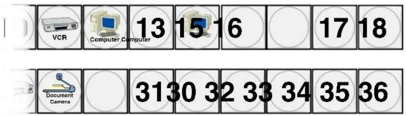
Figure 17. Sample Button Labels and Icons
Rear Panel Power Indicators
The two, primary and redundant, power supply modules (see figure 18) each have a 2-color LED.
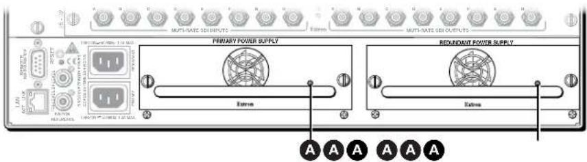
Figure 18. Rear Panel Power Supply Indicators
A Primary and Redundant Power Supply LEDs —
Green — Indicates that the associated power supply is operating within normal tolerances.
Red — Indicates that the associated power supply is operating outside the normal tolerances or has failed. See Removing and Installing a Power Supply Module on page 115 to replace the power supply.
Front Panel Operations
The following sections detail the power-up process and then provide sample procedures for the following actions:
- Creating ties, sets of ties, and configurations
- Changing a configuration
- Viewing ties, sets of ties, and configurations
- Creating I/O groups
- Saving a preset
- Recalling a preset
- Muting and unmuting outputs
- Locking and unlocking the front panel
• Performing front panel resets - Toggling background illumination on and off
- Reading and setting the Remote RS-232/RS-422 port settings
Definitions
The following terms apply to Extron matrix switchers, and are used throughout this guide:
Tie — An input-to-output connection.
Set of ties — An input tied to two or more outputs. (An output can never be tied to more than one input.)
Configuration — May consist of one tie or one or more sets of ties.
Current configuration — The configuration that is currently being used (also called configuration 0).
Global memory preset — A configuration that has been stored. The FOX Matrix 3200 can store up to 32 global memory presets in memory and the FOX Matrix 7200 can store up to 64 presets. When a global preset is retrieved from memory, it becomes the current configuration.
Room — A Room consists of a smaller subset of virtual outputs that are logically related to each other, as determined by the operator. The switchers support up to 32 rooms, each of which consists of 1 to 16 virtual outputs.
Room memory preset — A configuration consisting of virtual outputs in a single room that has been stored. When a room preset is retrieved from memory, it becomes the current configuration. The switchers support up to 10 room presets per room. Selecting a room preset only changes the ties to outputs that are assigned to that room. All other ties outside the room are not affected.
Power
Apply power by connecting one or both power cords between the Primary and Redundant AC power connectors and the AC sources. The switcher performs a self-test that flashes the front panel button indicators various colors and then turns them either off or to background illumination. An error-free power-up self-test sequence leaves all input, output, and control buttons either unlit or showing background illumination.
The current configuration and all presets are saved in non-volatile memory. When power is applied, the most recent configuration is retrieved. The previous presets remain intact.
If an error occurs during the self-test, the switcher locks up and fails to respond to commands or button pushes. If your switcher locks up on power-up, call the Extron S3 Sales and Technical Support Hotline (see the contact numbers listed on the Extron webpage for the office nearest you).
Creating a Configuration
The current configuration can be changed using the front panel buttons. Change the current configuration as follows:
- Press the Esc button to clear any front panel button indications that may be lit.
-
Select the desired input and output(s) by pressing the input and output buttons.
-
To indicate potential ties, output buttons blink when an input is selected.
- To indicate current ties, output buttons light steadily when an input is selected.
-
To clear unwanted outputs, press and release the associated lit output buttons. To indicate potential unties, output buttons blink when an output is deselected but not untied from the input.
-
Press and release the Enter button to accept the tie or to break an existing tie.
-
Repeat steps 1 through 3 to create or clear additional ties until the desired configuration is complete.
NOTES:
- Only one input can be tied to an output.
- If a tie is made between an input and an output, and the selected output was previously tied to another input, the older tie is broken in favor of the newer tie.
- If an input with no tie is selected, only the button for the selected input lights.
- As each input and output is selected, the associated output button blinks to indicate a tentative tie. Buttons for outputs that were already tied to the input light steadily. Outputs that are already tied can be left on, along with new blinking selections, or toggled off by pressing the associated output button.
- If you press the input button for an input that is I/O grouped (see I/O grouping on page 33) and then try to select an output in a different group, you cannot select the associated output button. The associated input button remains lit.
- An optical input can be tied to one or more of both the optical and SDI/HD-SDI outputs, and an SDI/HD-SDI input can be tied to one or more of both the SDI/HD-SDI and optical outputs.
Example 1: Create a set of ties
In the following example, input 5 is tied to outputs 3, 4, and 8. The steps show the front panel indications that result from your actions.
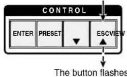
- Clear all selections: Press and release the Esc button.
Press the Esc button to clear all selections.
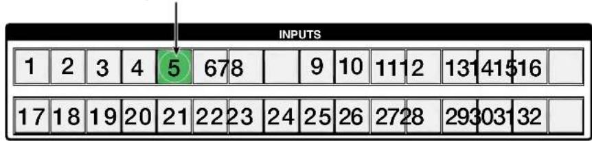
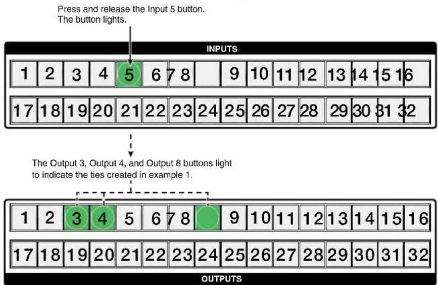
- Select an input: Press and release the Input 5 button.
Press and release the Input 5 button.
The button lights.
- Select the outputs: Press and release the output 3, output 4, and output 8 buttons.
Press and release the Output 3, Output 4, and Output 8 buttons.
The buttons blink to indicate that the selected input will be tied
to these outputs.
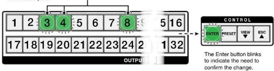
NOTE: You can cancel the entire set of ties at this point by pressing and releasing the Esc button. The Esc button flashes once.
- Confirm the change: Press and release the Enter button.
Press the Enter button to
confirm the configuration
change.

flowchart
graph TD
    A["ENTER"] --> B["All input buttons and output buttons return to unlit or background illumination"]
The Enter button returns to
unlit or background
The current configuration (see figure 19) is now input 5 tied to output 3, output 4, and output 8.
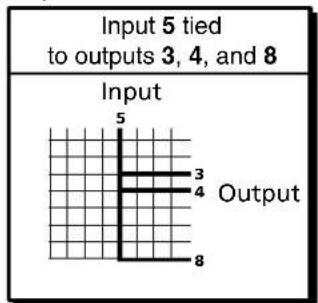
Figure 19. Final Configuration, Example 1
Example 2: Add a tie to a set of ties
In the following example, a new tie is added to the current configuration. The example shows the front panel indications that result from your actions.
NOTE: This example assumes that you have performed example 1 on the previous page.
- Clear all selections: Press and release the Esc button.
- Select an input: Press and release the Input 5 button.
flowchart
graph TD
    A["Press and release the Input 5 button.<br>The button lights."] --> B["INPUTS"]
    B --> C["1 2 3 4 5 6 7 8 9 10 11 12 13 14 15 16"]
    B --> D["17 18 19 20 21 22 23 24 25 26 27 28 29 30 31 32"]
    E["The Output 3, Output 4, and Output 8 buttons light to indicate the ties created in example 1."] --> F["OUTPUTS"]
    F --> G["1 2 3 4 5 6 7 8 9 10 11 12 13 14 15 16"]
    F --> H["17 18 19 20 21 22 23 24 25 26 27 28 29 30 31 32"]
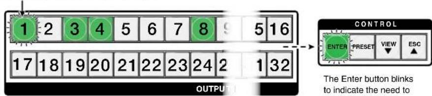
- Select the output: Press and release the Output 1 button.
Press and release the Output 1 button. The button blinks to indicate that the selected input will be tied to this output.
4. Confirm the change: Press and release the Enter button.
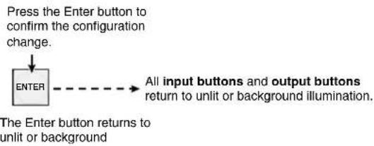
flowchart
graph TD
    A["Press the Enter button to confirm the configuration change."] --> B["ENTER"]
    B --> C["All input buttons and output buttons return to unlit or background illumination."]
The current configuration (see figure 20) is now input 5 tied to output 1, output 3, output 4, and output 8.
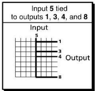
Figure 20. Final Configuration, Example 2
Example 3: Remove a tie from a set of ties
In the following example, an existing tie is removed from the current configuration. The example shows the front panel indications that result from your actions.
NOTE: This example assumes that you have performed example 1 on page 27 and example 2 on the previous page.
- Clear all selections: Press and release the Esc button.
- Select an input: Press and release the input 5 button.
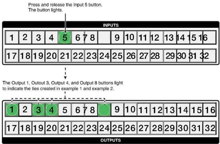
flowchart
graph TD
    A["Press and release the Input 5 button.<br>The button lights."] --> B["INPUTS"]
    B --> C["1 2 3 4 5 6 7 8 9 10 11 12 13 14 15 16"]
    B --> D["17 18 19 20 21 22 23 24 25 26 27 28 29 30 31 32"]
    E["The Output 1, Output 3, Output 4, and Output 8 buttons light to indicate the ties created in example 1 and example 2."] --> F["OUTPUTS"]
    F --> G["1 2 3 4 5 6 7 8 9 10 11 12 13 14 15 16"]
    F --> H["17 18 19 20 21 22 23 24 25 26 27 28 29 30 31 32"]
3. Select the output: Press and release the Output 4 button.
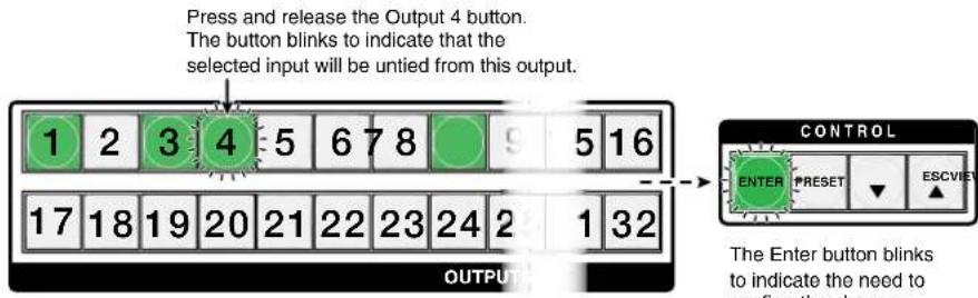
4. Confirm the change: Press and release the Enter button.
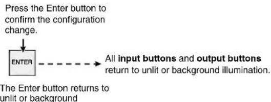
flowchart
graph TD
    A["Press the Enter button to confirm the configuration change."] --> B["ENTER"]
    B --> C["All input buttons and output buttons return to unlit or background illumination."]
The current configuration (see figure 21) is now input 5 video is tied to output 1, output 3, and output 8.
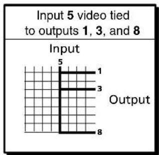
Figure 21. Final Configuration, Example 3
Viewing the Configuration
The current configuration can be viewed using the front panel buttons. The View-only mode prevents inadvertent changes to the current configuration. View-only mode also provides a way to mute outputs (see Muting and Unmuting Outputs on page 39).
View the current configuration as follows:
- Press the Esc button to clear any front panel button indications that may be lit.
- Press and release the View button. All of the buttons light for outputs that are not tied.
- Select the desired input or output whose ties you wish to view by pressing the input or output buttons.
NOTES:
- When you enter View-only mode, the output buttons light for all outputs without ties. Likewise, when you press an output button for which there are no ties, the output buttons light for all outputs without ties.
- To see all ties of the current configuration, press and release each input and output button, one at a time.
- After 30 seconds of front panel inactivity, View-only mode automatically deselects.
Example 4: Viewing ties
In the following example, we view the ties in the current configuration. The steps show the front panel indications that result from your actions.
NOTE: This example assumes that you have performed example 1 on page 27, example 2 on page 28, and example 3 on page 29.
- Clear all selections: Press and release the Esc button.
- Select View-only mode: Press and release the View button. The View button lights.
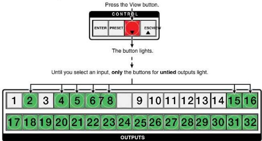
flowchart
graph TD
    A["Press the View button."] --> B["CONTROL"]
    B --> C["ENTER"]
    B --> D["PRESET"]
    B --> E["ESCVIEW"]
    C --> F["The button lights."]
    D --> F
    E --> F
    F --> G["Until you select an input, only the buttons for untied outputs light."]
    G --> H["OUTPUTS"]
    H --> I["1 2 3 4 5 6 7 8 9 10 11 12 13 14 15 16"]
    I --> J["17 18 19 20 21 22 23 24 25 26 27 28 29 30 31 32"]
3. Select an input: Press and release the Input 5 button.
Press and release the Input 5 button. The button lights.
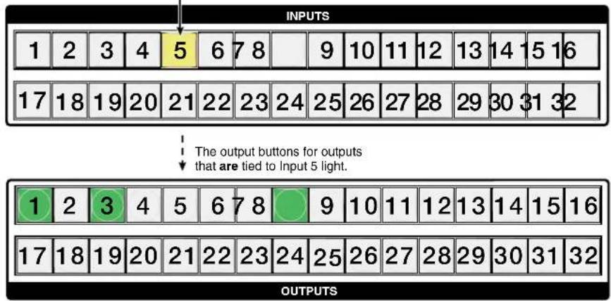
The output buttons for outputs that are not tied to Input 5 are either unlit or background illuminated.
NOTE: You can also view a set of ties by selecting a tied output. Demonstrate this as follows:
• Note the number of a lit output button.
- Then press and release the output button for an untied (unlit or background illumination) output.
- Observe that all of the untied outputs light.
- Then press the output button that you noted previously.
- Observe that the selected output button, the tied input button (input 5), and the output buttons light for all of the outputs that are tied to the input.
4. Exit View-only mode: Press and release the View button
Press the View button to exit View-Only mode.

The View button returns to unlit or background illumination.
I/O Grouping
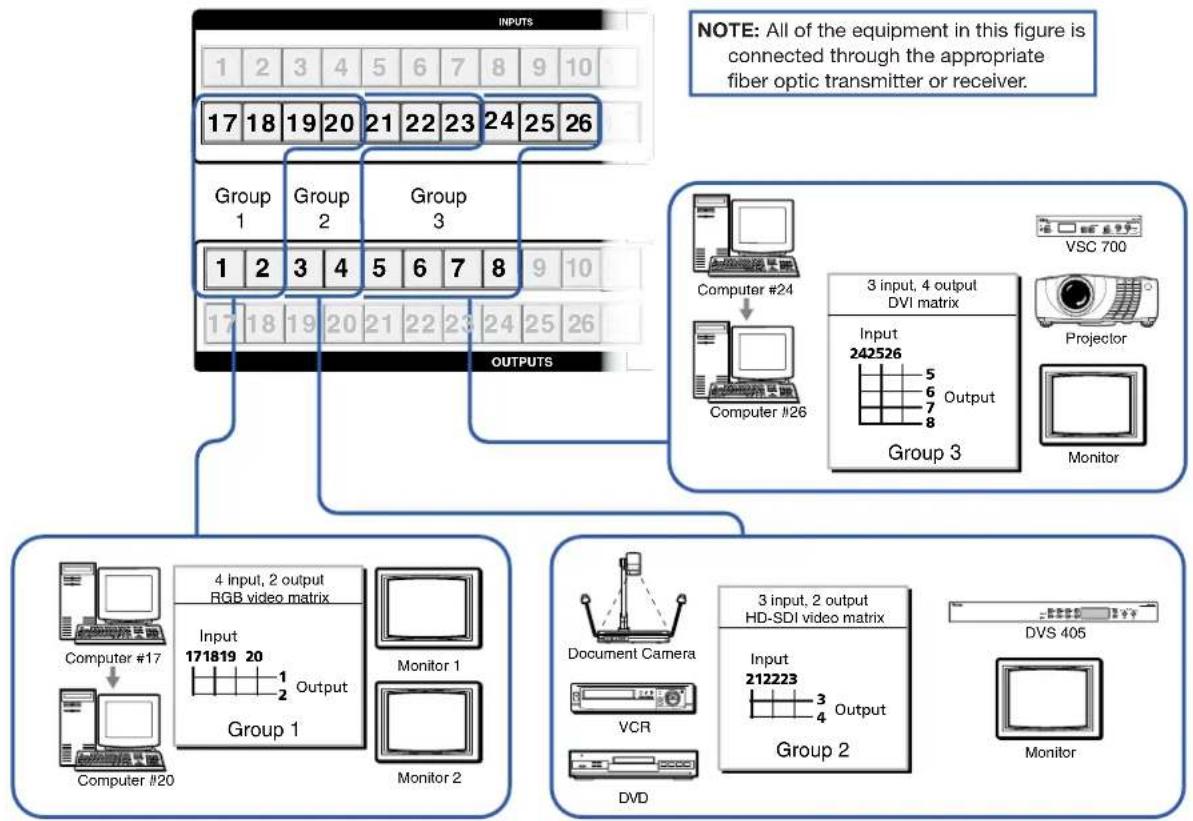
I/O grouping (see figure 22) is a matrix switcher feature that allows you to subdivide the front panel controls of the matrix into four smaller functional sub-switchers and limit tie creation using the front panel only. Inputs and outputs can be assigned to one of four groups or not assigned to any group.
flowchart
graph TD
    A["INPUTS"] --> B["Group 1"]
    A --> C["Group 2"]
    A --> D["Group 3"]
    A --> E["OUTPUTS"]
    B --> F["4 Input, 2 output RGB video matrix"]
    C --> G["171819 20 Output"]
    D --> H["5 6 7 8"]
    E --> I["17 18 19 20 21 22 23 24 25 26"]
    F --> J["Computer #17"]
    G --> K["Monitor 1"]
    H --> L["Monitor 2"]
    I --> M["Document Camera"]
    I --> N["VCR"]
    I --> O["DVD"]
    J --> P["3 input, 2 output HD-SDI video matrix"]
    K --> Q["3 input, 2 output HD-SDI video matrix"]
    L --> R["3 input, 2 output HD-SDI video matrix"]
    M --> S["Output Matrix"]
    N --> T["Output Matrix"]
    O --> U["Output Matrix"]
    P --> V["3 input, 4 output DVI matrix"]
    Q --> W["3 input, 4 output DVI matrix"]
    R --> X["Output Matrix"]
    S --> Y["Output Matrix"]
    T --> Z["VSC 700"]
    U --> AA["Projection"]
    V --> AB["Monitor"]
Figure 22. I/O Grouping of Incompatible Video Formats
NOTE: The I/O grouping feature is tied into the Switch Reference connectors on the switcher. Ties to any input in I/O group 1 use the tri-level sync reference. Ties to any output in I/O group 2 use the bi-level sync reference. Assign sync-critical inputs and outputs to the appropriate I/O groups.
When you are creating ties on the front panel, inputs and outputs that are assigned to a group can be tied only to other outputs and inputs within the same group. For example, a front panel operator cannot tie an input that is assigned to group 1 to an output that is assigned to group 2. Ungrouped inputs and outputs can be switched to outputs and inputs in any group. Ties between groups (an input in group 1 tied to an output in group 2) can be created under serial port or Ethernet control.
Suggested applications for the I/O grouping feature include:
- Segregating sync-critical inputs and outputs
- Segregating specific video formats to prevent an input in one video format from being inadvertently applied to an output device that supports another video format
- Segregating input and output devices that are in separate rooms
- Segregating incompatible fiber signals, such as those from a FOX 500 system and those from a FOX HD-SDI system
- Isolating video from being displayed on specific output devices for operational security reasons
The I/O groups can be set up on the front panel or by using the Remote port, Configuration port, or LAN ports and either the SIS (see the Programming Guide section, beginning on page 52) or the Matrix Switchers Control Program (see the Matrix Software section, beginning on page 71).
Create I/O groups on the front panel as follows:
NOTE: I/O groups are protected when front panel Lock mode 2 is selected. You can view the groups in Lock mode 2, but you cannot change them from the front panel (see Locking the Front Panel (Executive Mode) on page 41).
- Press the Esc button to clear any front panel button indications that may be lit.
- To enter I/O Group mode, press and hold the Input 1 and Output 1 buttons until the input and output buttons light to display the ungrouped inputs and outputs.
-
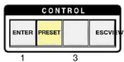
Press and release one of the Control buttons to select a group:
-
Press the Enter button to select group 1.
- Press the Preset button to select group 2.
- Press the View button to select group 3.
- Press the Esc button to select group 4.
- Select the one or more inputs and one or more outputs to assign to the group by pressing the input and output buttons.
- Allow the I/O Group mode to time out after approximately 30 seconds.
NOTES:
- Ties between groups (an input in group 1 tied to an output in group 2) can be created under serial port or Ethernet control.
- Ties that were created before I/O groups were created remain valid, even if they include inputs and outputs in different groups.
- Presets can be created under serial port or Ethernet control that tie inputs and outputs across group boundaries. These presets are selectable from the front panel.
- An input or output can be assigned to only one group. If you assign an input or output to a group and that input or output is already assigned to a different group, the older grouping is disboarded in favor of the new grouping.
- For I/O groups to have any function, at least two groups must be created.
Example 5: Grouping inputs and outputs
In the following example, several switcher inputs and outputs are assigned to groups. The steps show the front panel indications that result from your actions.
-
Clear all selections: Press and release the Esc button.
-
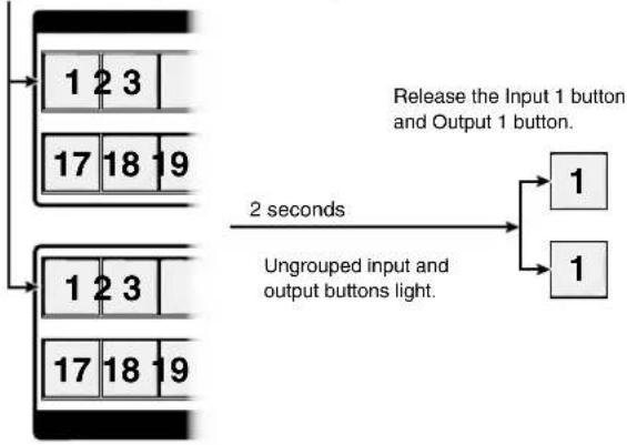
Enter I/O Group mode: Simultaneously press and hold the Input 1 and Output 1 buttons for approximately 2 seconds and then release the buttons.
Press and hold the Input 1 button and Output 1 button.
flowchart
graph TD
    A["Input 1 Button"] --> B["2 Second"]
    C["Input 2 Button"] --> D["2 Second"]
    E["Input 3 Button"] --> F["2 Second"]
    G["Output 1 Button"] --> H["2 Second"]
    I["Output 2 Button"] --> J["2 Second"]
    K["Output 3 Button"] --> L["2 Second"]
    M["Output 4 Button"] --> N["2 Second"]
    O["Output 5 Button"] --> P["2 Second"]
    Q["Output 6 Button"] --> R["2 Second"]
    S["Output 7 Button"] --> T["2 Second"]
    U["Output 8 Button"] --> V["2 Second"]
    W["Output 9 Button"] --> X["2 Second"]
    Y["Output 10 Button"] --> Z["2 Second"]
    AA["Output 11 Button"] --> AB["2 Second"]
    AC["Output 12 Button"] --> AD["2 Second"]
    AE["Output 13 Button"] --> AF["2 Second"]
    AG["Output 14 Button"] --> AH["2 Second"]
    AI["Output 15 Button"] --> AJ["2 Second"]
    AK["Output 16 Button"] --> AL["2 Second"]
    AM["Output 17 Button"] --> AN["2 Second"]
    AO["Output 18 Button"] --> AP["2 Second"]
    AQ["Output 19 Button"] --> AR["2 Second"]
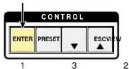
- Select group 1: Press and release the Enter button.
Press and release the Enter button to select group 1. The button lights to indicate the selection.
- Assign inputs and outputs to group 1:
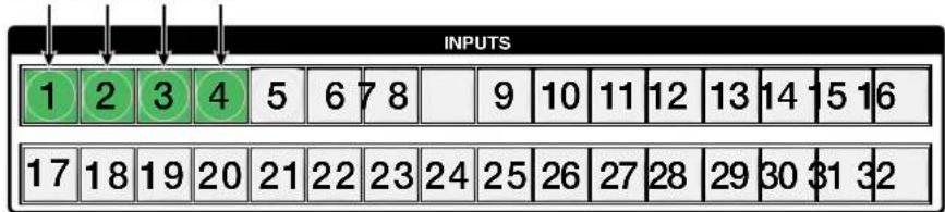
a. Press and release the Input 1 through Input 4 buttons.
One at a time, press and release the Input 1 through Input 4 buttons. The selected buttons light.
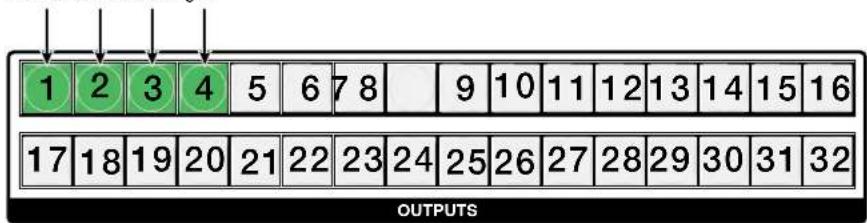
b. Press and release the Output 1 through Output 4 buttons.
One at a time, press and release the Output 1 through Output 4 buttons. The selected buttons light.
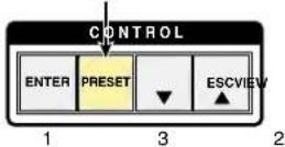
- Select group 2: Press and release the Preset button.
Press and release the Preset button to select group 2. The button lights to indicate the selection.
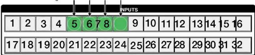
- Assign inputs and outputs to group 2:
a. Press and release the Input 5 through Input 8 buttons.
One at a time, press and release the Input 5 through Input 8 buttons. The selected buttons light.
b. Press and release the Output 5 through Output 8 buttons.
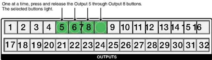
- Do nothing for approximately 30 seconds. The switcher exits I/O Group mode.
In this example:
- Group 1 consists of inputs 1 through 4 and outputs 1 through 4.
• Group 2 consists of inputs 5 through 8 and outputs 5 through 8.
Using Presets
The current configuration (configuration 0) can be saved as a preset in any one of 32 (FOX Matrix 3200) or 64 (FOX Matrix 7200) preset memory addresses. Presets can be saved and recalled from the front panel. The preset locations are assigned to input buttons 1 through 32 (64). When a preset is retrieved from memory, it becomes the current configuration.
NOTES:
- Presets cannot be viewed from the front panel unless they are recalled as the current configuration. Presets can be viewed using the Extron matrix switchers Control Program (see the Presets menu description in the "Matrix Software" section on page 87).
- The current configuration and all presets are stored in non-volatile memory. When power is removed and restored, the current configuration is still active and all presets are retained.
- When a preset is recalled, it replaces the current configuration, which is lost unless it is also stored as a preset. The recalled preset overwrites all of the current configuration ties in favor of the preset configuration ties.
Example 6: Saving a preset
In the following an example, the current configuration is saved as a preset. The example shows the front panel indications that result from your actions.
- Clear all selections: Press and release the Esc button.
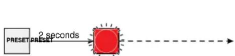
- Select Save Preset mode: Press and hold the Preset button for approximately 2 seconds until it blinks.
flowchart
graph LR
    A["PRESET"] --> B["2 seconds"]
    B --> C["Target"]
Press and hold the Preset button until it blinks.
All input buttons with assigned presets light.
If you then save the configuration to a lit preset number,
the configuration data at that preset location will be overwritten.
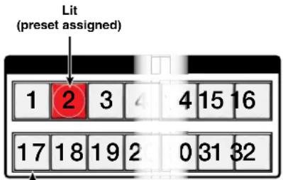
Unlit (no preset assigned)
- Select the preset: Press and release the input button or output button for the desired preset.
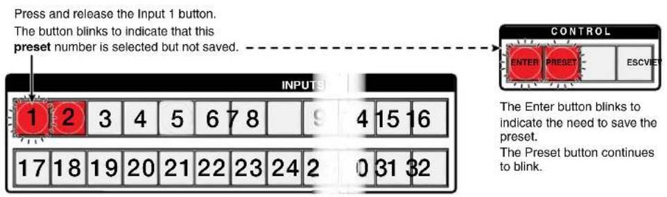
- Save the Preset: Press and release the Enter button to save the preset. The current configuration is now stored in the selected memory location.
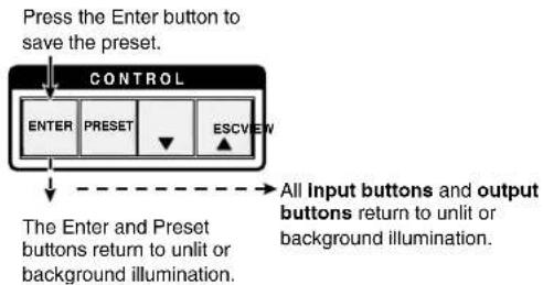
flowchart
graph TD
    A["Press the Enter button to save the preset."] --> B["CONTROL"]
    B --> C["ENTER"]
    B --> D["PRESET"]
    B --> E["ESCVIEW"]
    C --> F["The Enter and Preset buttons return to unlit or background illumination."]
    D --> F
    E --> F
    F --> G["All input buttons and output buttons return to unlit or background illumination."]
Example 7: Recalling a preset
In the following example, a preset is recalled to become the current configuration. The steps show the front panel indications that result from your actions.
- Clear all selections: Press and release the Esc button.
- Select Recall Preset mode: Press and release the Preset button.
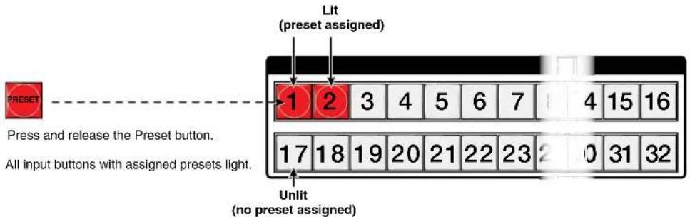
- Select the preset: Press and release the input button or output button for the desired preset.
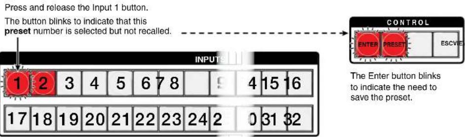
- Recall the preset: Press and release the Enter button. The configuration stored in the selected memory location is now the current configuration and can be viewed in the View-only mode (see example 4 on page 31).
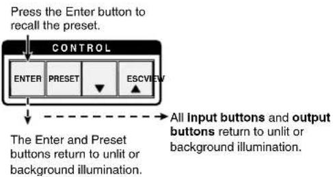
flowchart
graph TD
    A["Press the Enter button to recall the preset."] --> B["CONTROL"]
    B --> C["ENTER"]
    B --> D["PRESET"]
    B --> E["ESCVIEW"]
    C --> F["The Enter and Preset buttons return to unlit or background illumination."]
    D --> F
    E --> F
    F --> G["All input buttons and output buttons return to unlit or background illumination."]
Muting and Unmuting Outputs
Individual outputs can be muted or unmuted as follows:
NOTE: Output mutes are protected when front panel Lock mode 2 is selected. You can view the status of the output (muted or unmuted) in Lock mode 2 but you cannot change it from the front panel (see Locking the Front Panel (Executive Mode) on page 41).
- Press the Esc button to clear any front panel button indications that may be lit.
- Press and release the View button.
- One at a time, press and hold the button for the desired output for approximately 2 seconds. The output button for the selected output blink to indicate the mute or return to their previous state to indicate the unmute.
- Press and release the View button to return to normal switcher operation.
NOTES:
- When you enter View-only mode, the output LEDs turn on for all outputs without ties.
- Mutes are saved to non-volatile memory. When power is removed and restored, the mute settings are retained.
Example 8: Muting and unmuting an output
In the following example, a switcher output is muted and unmuted. The steps show the front panel indications that result from your actions.
NOTE: This example assumes that you have performed example 1 on page 27, example 2 on page 28, and example 3 on page 29.
- Clear all selections: Press and release the Esc button.
- Select View-only mode: Press and release the View button. The View button lights.
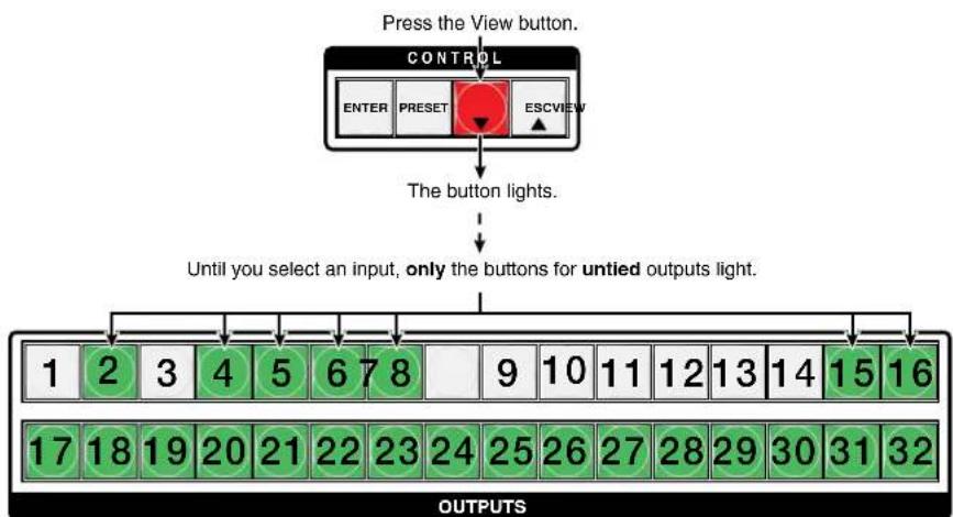
flowchart
graph TD
    A["Press the View button. CONTROL"] --> B["ENTER"]
    A --> C["PRESET"]
    A --> D["ESCVIEW"]
    B --> E["The button lights."]
    C --> E
    D --> E
    E --> F["Until you select an input, only the buttons for untied outputs light."]
    F --> G["OUTPUTS 1 2 3 4 5 6 7 8 9 10 11 12 13 14 15 16"]
    G --> H["OUTPUTS 17 18 19 20 21 22 23 24 25 26 27 28 29 30 31 32"]
- Mute the outputs: One at a time, press and hold the Output 3 button and then the Output 4 button for approximately 2 seconds until each button begins to blink. The output 3 and output 4 signals are muted.
Mute outputs one at a time.
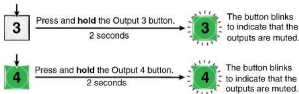
flowchart
graph TD
    A["3"] -->|Press and hold the Output 3 button.
2 seconds| B["3"]
    C["4"] -->|Press and hold the Output 4 button.
2 seconds| D["4"]
    B --> E["The button blinks to indicate that the outputs are muted."]
    D --> F["The button blinks to indicate that the outputs are muted."]
NOTE: When you push Input 3, it lights and Input 4 returns to unlit because of ties made in example 1 on page 27, example 2 on page 28, and example 3 on page 29.
- Unmute the outputs: One at a time, press and hold the Output 3 button and then the Output 4 buttons for approximately 2 seconds until each button lights steadily. The output 3 and output 4 signals are unmuted.
Unmute outputs one at a time.
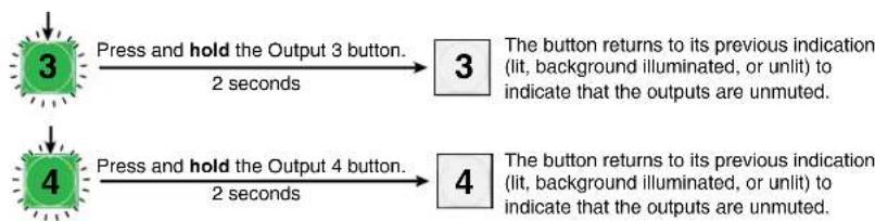
flowchart
graph TD
    A["3"] -->|Press and hold the Output 3 button.
2 seconds| B["3"]
    C["4"] -->|Press and hold the Output 4 button.
2 seconds| D["4"]
    B --> E["The button returns to its previous indication<br>(lit, background illuminated, or unlit) to indicate that the outputs are unmuted."]
    D --> F["The button returns to its previous indication<br>(lit, background illuminated, or unlit) to indicate that the outputs are unmuted."]
- Exit View-only mode: Press and release the View button.
Press the View button to exit View-Only mode.

The View button returns to unlit or background illumination.
Locking the Front Panel (Executive Mode)
The front panel security lockout limits the operation of the switcher from the front panel. When the switcher is locked, all of the front panel functions are disabled except for the View-Only mode functions and deselecting the front panel Lock mode (see Viewing the Configuration on page 31). Other than in View-Only mode, if the user pushes a front panel button when the switcher is locked, the View and Preset buttons flash twice and return to their previous state.
To toggle the lock on and off, press and hold the Enter button and the Esc button for approximately two seconds (see figure 23).
Press and hold the Enter and Esc buttons simultaneously to toggle Executive mode on or off.

flowchart
graph LR
    A["CONTROL"] --> B["ENTER"]
    A --> C["PRESSET"]
    A --> D["ESCVIEW"]
    D --> E["2 seconds"]
    E --> F["CONTROL"]
    F --> G["ENTER"]
    F --> H["PRESSET"]
    F --> I["ESCVIEW"]
    I --> J["2 seconds"]
    J --> K["The Preset and View buttons blink twice to indicate the mode change. Release the buttons."]
Figure 23. Toggling Front Panel Lock On and Off
Performing a System Reset from the Front Panel
The front panel reset is identical to issuing the Esc/XXX← SIS command (see page 64). A system reset clears all ties and presets and resets all I/O grouping.
NOTES:
- You must apply power from an unpowered state. Applying the redundant power with primary power already applied does not reset the switcher.
- System reset does not reset the Internet protocol (IP) settings or replace user-installed firmware.
Reset the switcher to the factory default settings by pressing and holding the View button and Esc button simultaneously while you apply AC power to the switcher (see figure 24).
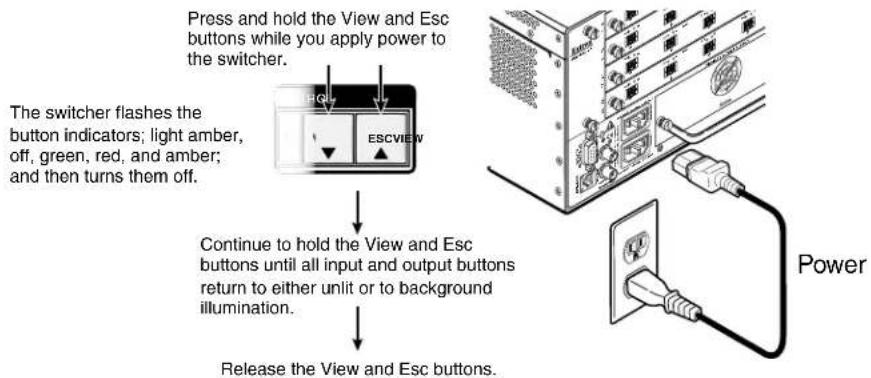
flowchart
graph TD
    A["Press and hold the View and Esc buttons while you apply power to the switcher."] --> B["The switcher flashes the button indicators; light amber, off, green, red, and amber; and then turns them off."]
    B --> C["Continue to hold the View and Esc buttons until all input and output buttons return to either unlit or to background illumination."]
    C --> D["Release the View and Esc buttons."]
Figure 24. System Reset
NOTE: If background illumination was turned on before the reset, the I/O and control buttons are unlit after the reset. But, when you cycle power, background illumination returns to as selected.
Background Illumination
The buttons on the front panel can be set to provide amber background illumination at all times or the background illumination can be turned off. To toggle the background illumination on or off, press and hold the Input 1 and Input 2 buttons simultaneously for approximately 2 seconds (see figure 25).
Press and hold the Input 1 and Input 2
buttons simultaneously to toggle
background illumination mode on or off.
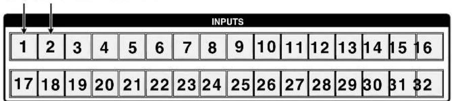
After approximately 2 seconds, release
the Input 1 and Input 2 buttons.
Figure 25. Toggle Background Illumination On or Off
Selecting the Rear Panel Remote Port Protocol and Baud Rate
All switchers can support either RS-232 or RS-422 serial communication protocol and can operate at the 9600, 19200, 38400, and 115200 baud rate. The settings of these variables can be viewed and changed from the front panel.
View and configure the serial communications settings as follows:
- Select Serial Port Selection and Configuration mode: Simultaneously press and hold all Control buttons (Enter, Preset, View, and Esc).
Press and hold the Enter, Preset,
View, and Esc buttons.
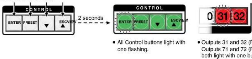
flowchart
graph LR
    A["CONTROL"] --> B["ENTER"]
    A --> C["PRESSET"]
    A --> D["ESCVIEW"]
    D --> E["2 seconds"]
    E --> F["CONTROL"]
    F --> G["ENTER"]
    F --> H["PRESSET"]
    F --> I["ESCVIEW"]
    I --> J["0:31 32"]
    style F fill:#ffcccc,stroke:#333
    note right of F All Control buttons light with one flashing.
    note right of G Outputs 31 and 32 (F) Outputs 71 and 72 (F) both light with one bu
The flashing Control button indicates the baud rate as follows:
Enter — 9600 Preset — 19200
View — 38400 Esc — 115200
The flashing output button indicates the protocol as follows:
Output 31 (71) — RS-232 Output 32 (72) — RS-422
In this example, the port is set to RS-232 at 9600 baud.
-
Release the Control buttons.
-
Change a value: Press and release the button that relates to the desired value.
Press and release the button(s) to configure the port as follows:
Baud rate:
Enter — 9600 Preset — 19200
View — 38400 Esc — 115200
Serial protocol:
Output 31 (71) — RS-232 Output 32 (72) — RS-422
The selected buttons blink and the others remain lit.
In this example, the port is set to RS-422 at 38400 baud.
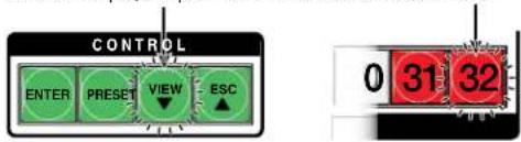
- Exit the Serial Port Selection and Configuration mode: Press and release an output button.
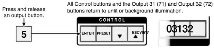
flowchart
graph TD
    A["Press and release an output button."] --> B["5"]
    B --> C["CONTROL"]
    C --> D["ENTER"]
    C --> E["PRESET"]
    C --> F["ESCVIEW"]
    D --> G["03132"]
    E --> G
    F --> G
    style A fill:#f9f,stroke:#333
    style B fill:#ccf,stroke:#333
    style C fill:#cfc,stroke:#333
    style D fill:#fcc,stroke:#333
    style E fill:#cff,stroke:#333
    style F fill:#ffc,stroke:#333
Reset Operations
The rear panel has a Reset button that initiates four levels of resets (numbered 1, 3, 4, and 5 for the sake of comparison with an Extron IPL product). The Reset button is recessed, so use a small screwdriver, a pointed stylus, or a ballpoint pen.
For different reset levels, press and hold the button while the switcher is running or press and hold the button while you apply power to the switcher.
See the table on the next page for a summary of the modes.
ATTENTION:
NOTE: The reset modes listed on the next page close all open IP and Telnet connections and close all sockets. Also, the following modes are separate functions, not a continuation from Mode 1 to Mode 5.
| Mode | Activation Result Purpose and Notes | ||
| 1 | Hold down the recessedResetbutton while applying power to the switcher.NOTE: After a mode 1 reset is performed, update the switcher firmware to the latest version. Do not operate the switcher firmware version that results from the mode 1 reset. If you want to use the factory default firmware, you must upload that version again (see theMatrix Softwaresection on page 82 for details on uploading firmware). | The switcher reverts to the factory default firmware. Event scripting will not start if the switcher is powered on in this mode. All user files and settings (such as drivers, adjustments, and IP settings) are maintained.NOTE: If you do not want to update firmware, or you performed a mode 1 reset by mistake, cycle power to the switcher to return to the firmware version that was running before the mode 1 reset. Use the0Q SIS command (see page 65) to confirm that the factory default firmware is no longer running (look for the asterisk [*] following the version number. | Use mode 1 to revert to the factory default firmware version if incompatibility issues arise with user-loaded firmware. |
| 3 | Hold down theResetbutton for about 3 seconds, until the Reset LED blinks once, then press and releaseResetwithin 1 second. | Mode 3 turns events on or off. During resetting, the Reset LED flashes 2 times if events are starting, 3 times if events are stopping. | Mode 3 is useful for troubleshooting. |
| 4 | Hold down theResetbutton for about 6 seconds, until the Reset LED blinks twice (once at 3 seconds and again at 6 seconds). Then press and releaseResetwithin 1 second. | Mode 4:Enables ARP capability.Sets the IP address to the factory default.Sets the subnet address to the factory default.Sets the gateway address to the factory default.Sets port mapping to the factory default.Turns DHCP off.Turn events off.The Reset LED flashes four times in quick succession during the reset. | Mode 4 enables you to set IP address information using ARP and the MAC address. |
| 5 | Hold down theResetbutton for about 9 seconds, until the Reset LED blinks three times (once at 3 seconds, again at 6 seconds, and then again at 9 seconds). Then press and releaseResetwithin 1 second.NOTES:Mode 5 reset clears most adjustments. To save these settings, use the Windows-based Matrix Switchers Control Program and theFile >Save MATRIX settings as... selection before you perform this reset (see theMatrix Softwaresection on page 87).The factory configured passwords for all accounts on this device have been set to the device serial number. In the event of a complete system reset, the password reverts to the default, which is no password (seeSet Password SIS commandson page 68 to change the password). | Mode 5 performs a complete reset to factory defaults (with the exception of the firmware):Does everything mode 4 does.Resets most all real time adjustments, including: clears all ties and presets clears all mutes clears all I/O grouping Resets all IP options.Removes and clears all files for the switcher. The reset LED flashes four times in quick succession during the reset. | Mode 5 is useful if you want to start over with configuration and uploading or to replace events.Same asEscZQQQSIS command (see page 64). |
Performing Soft System Resets (Resets 3, 4, and 5)
Perform a soft reset of the switcher as follows:
- Use an Extron Tweeker or other small screwdriver to press and hold the rear panel Reset button until the front panel View and Esc buttons blink the number of times for the desired reset: once (events reset), twice (system reset), or three times (absolute reset) (see figure 26).
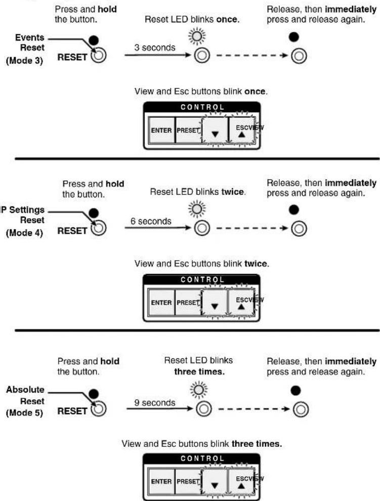
flowchart
graph TD
    A["Events Reset (Mode 3)"] --> B["RESET"]
    B --> C["Press and hold the button."]
    C --> D["Reset LED blinks once."]
    D --> E["3 seconds"]
    E --> F["Release, then immediately press and release again."]
    F --> G["View and Esc buttons blink once."]
    G --> H["CONTROL"]
    H --> I["ENTER PRESET ESCVIEW"]
    J["P Settings Reset (Mode 4)"] --> K["RESET"]
    K --> L["Press and hold the button."]
    L --> M["Reset LED blinks twice."]
    M --> N["6 seconds"]
    N --> O["Release, then immediately press and release again."]
    O --> P["View and Esc buttons blink twice."]
    P --> Q["CONTROL"]
    Q --> R["ENTER PRESET ESCVIEW"]
    S["Absolute Reset (Mode 5)"] --> T["RESET"]
    T --> U["Press and hold the button."]
    U --> V["Reset LED blinks three times."]
    V --> W["9 seconds"]
    W --> X["Release, then immediately press and release again."]
    X --> Y["View and Esc buttons blink three times."]
    Y --> Z["CONTROL"]
    Z --> AA["ENTER PRESET ESCVIEW"]
Figure 26. Soft System Resets
- Release the Reset button and then immediately press and release the Reset button again. Nothing happens if the second momentary press does not occur within 1 second.
Performing a Hard Reset (Reset 1)
The hard reset function restores the switcher to the base firmware that it was shipped with. After a hard reset, events do not automatically start, but user settings and files are restored. Perform a hard reset as follows:
NOTE: The hard reset restores the factory-installed firmware. The switcher reverts to that factory firmware the next time power is cycled off and on unless a firmware update is performed before the power cycle.
- If necessary, turn off power to the switcher.
- Press and hold the Reset button on the rear panel while you apply AC power either switcher power connector (see figure 27).
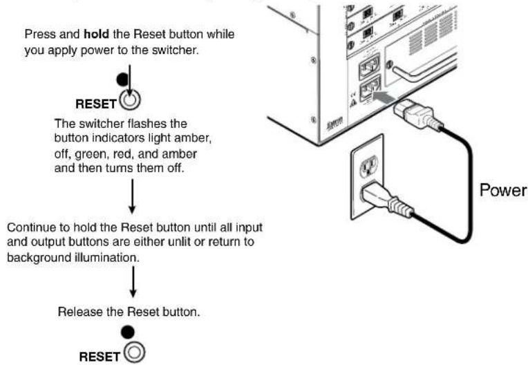
flowchart
graph TD
    A["Press and hold the Reset button while you apply power to the switcher."] --> B["RESET"]
    B --> C["The switcher flashes the button indicators light amber, off, green, red, and amber and then turns them off."]
    C --> D["Continue to hold the Reset button until all input and output buttons are either unlit or return to background illumination."]
    D --> E["Release the Reset button."]
    E --> F["RESET"]
Figure 27. Hard Reset
Troubleshooting
This section recommends what to do if you have problems operating the switcher.
- Ensure that all devices are plugged in and powered on.
- Check to see if one or more outputs are muted.
- Ensure an active input is selected for output on the switcher.
- Ensure that the proper signal format is supplied.
- Check the cabling and make corrections as necessary.
- Call the Extron S3 Sales and Technical Support Hotline if necessary (see the contact numbers on the last page of this guide for the Extron office nearest you).
Configuration Worksheets
Rather than trying to remember the configuration for each preset, use worksheets to record this information. Make copies of the blank worksheet on page 50 or page 51 and use one for each preset configuration. Cross out all unused or inactive inputs and outputs.
NOTE: All of the equipment in the following examples is connected through the appropriate fiber optic transmitter or receiver.
Worksheet Example 1: System equipment
Figure 28 shows a worksheet for a switcher configured as a 24-input by 24-output matrix in a fictional organization with the system hardware annotated. Inputs 10 and 11 have no connections in this organization, so they have been crossed out on the worksheet. Inputs 25 through 32 do not exist on this model, so they are crossed out. Similarly, outputs 7, 14, 15, 16, and 25 through 32 are crossed out on the worksheet.
Extron

flowchart
graph LR
    A["CONFIG"] --> B["4.5 PIP"]
    B --> C["AUTO"]
    C --> D["SWAP"]
    D --> E["Output"]
Figure 28. Worksheet Example 1: System Equipment
Inputs include PCs, an audio CD player, cameras, and a signal generator. Output devices include monitors, front and rear projectors, a stereo, and a VCR for recording presentations.
The signal generator connected to input 12 enables a video test pattern to be sent to one, several, or all output devices for problem isolation or adjustment purposes. An audio test tape or CD could be used in a similar manner to check the audio components.
Worksheet Example 2: Daily Configuration
Figure 29 continues from worksheet example 1 by showing the ties that make up the configuration of preset 1. Black lines show one configuration, green lines a second configuration, and red lines a third configuration.
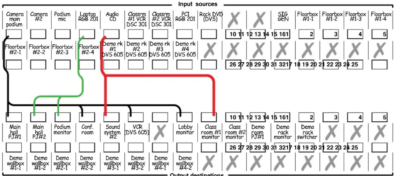
flowchart
graph TD
    A["Input sources"] --> B["Camera main podium"]
    A --> C["Floorbox #2-1"]
    A --> D["Main hall PJ#1"]
    A --> E["Demo wallbox #1-1"]

    B --> F["Camera #2"]
    B --> G["Floorbox #2-2"]
    B --> H["Main hall PJ#2"]

    C --> I["Camera #2"]
    C --> J["Floorbox #2-3"]
    C --> K["Demo wallbox #2-4"]

    D --> L["Main hall PJ#2"]
    D --> M["Demo wallbox #1-2"]

    E --> N["Camera #2"]
    E --> O["Floorbox #2-3"]
    E --> P["Demo wallbox #2-4"]

    F --> Q["Laptop RGB 201"]
    G --> R["Laptop RGB 201"]
    H --> S["Laptop RGB 201"]

    I --> T["Audio CD"]
    J --> U["Demo rk #1 DVS 605"]
    K --> V["Demo rk #2 DVS 605"]
    L --> W["Demo rk #3 DVS 605"]

    M --> X["Demo wallbox #3-1"]
    N --> Y["Demo wallbox #3-2"]
    O --> Z["Demo wallbox #3-3"]

    P --> AA["Demo wallbox #4-1"]
    Q --> AB["Demo wallbox #4-2"]

    R --> AC["Demo wallbox #4-2"]

    S --> AD["Lobby monitor"]
    T --> AE["Lobby monitor"]

    U --> AF["Lobby monitor"]

    V --> AG["Lobby monitor"]

    W --> AH["Lobby monitor"]

    X --> AI["Lobby monitor"]

    Y --> AJ["Lobby monitor"]

    Z --> AK["Lobby monitor"]

    AA --> AL["Lobby monitor"]

    AB --> AM["Lobby monitor"]

    AC --> AN["Lobby monitor"]

    AD --> AO["Lobby monitor"]

    AE --> AP["Lobby monitor"]

    AF --> AQ["Lobby monitor"]

    AG --> AR["Lobby monitor"]

    AH --> AS["Lobby monitor"]

    AI --> AT["Lobby monitor"]

    AJ --> AU["Lobby monitor"]

    AK --> AV["Lobby monitor"]

    AL --> AW["Lobby monitor"]

    AM --> AX["Lobby monitor"]

    AN --> AY["Lobby monitor"]

    AO --> AZ["Lobby monitor"]

    AP --> BA["Lobby monitor"]

    AQ --> BB["Lobby monitor"]

    AR --> BC["Lobby monitor"]

    AS --> BD["Lobby monitor"]

    AT --> BE["Lobby monitor"]

    AU --> BF["Lobby monitor"]

    AV --> BG["Lobby monitor"]

    AW --> BH["Lobby monitor"]

    AX --> BI["Lobby monitor"]

    AY --> BJ["Lobby monitor"]

    ASX --> BK["Lobby monitor"]

    ATX --> BL["Lobby monitor"]

    AUXTL --> BM["Lobby monitor"]

    AVXTL --> BN["Lobby monitor"]

    AXXTL --> BO["Lobby monitor"]

    AYXTL --> BP["Lobby monitor"]

    ATXTL --> BXYL
Preset # ____ Title: ____
Fill in the preset number and use colors, or dashes, etc. to make connecting lines.
Figure 29. Worksheet Example 2: Daily Configuration
In this example:
- The image of the presenter, from the main podium camera (input 1), is:
• Displayed in the main hall (output 1)
- Displayed in the conference room (output 4) to the overflow crowd
• Displayed in the lobby (output 8)
• Tied to the VCR (output 6)
- The presenter has a presentation on her laptop computer (input 4) that is:
• Displayed in the main hall (output 2)
• Displayed locally on the podium (output 3)
• Music from the CD player (input 5) is:
- Played in the background in the main hall on sound system #2 (output 5)
- Played in Classroom 1 (output 9)
Worksheet Example 3: Test configuration
The AV system in our fictional organization needs to be fine tuned on a regular basis.
Figure 30 shows a typical test configuration, with a signal generator (input 12) generating a test pattern to all monitors (outputs 1, 2, 3, 4, 8, 9, 10, 11, and 12) and to the various wall boxes.
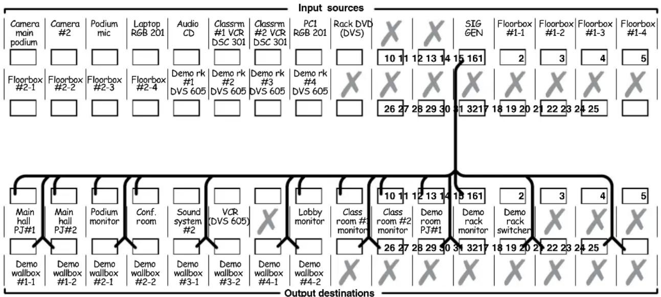
flowchart
graph TD
    A["Input sources"] --> B["Camera main podium"]
    A --> C["Floorbox #2-1"]
    A --> D["Floorbox #2-2"]
    A --> E["Demo rk #1 DVS 605"]
    A --> F["Laptop RGB 201"]
    A --> G["Classrm #1 VCR DSC 301"]
    A --> H["Classrm #2 VCR DSC 301"]
    A --> I["PCI RGB 201"]
    A --> J["Rack DVD (DVS)"]
    K["Output destinations"] --> L["Main hall PJ#1"]
    K --> M["Main hall PJ#2"]
    K --> N["Podium monitor"]
    K --> O["Conf. room"]
    K --> P["Sound system #2"]
    K --> Q["VCR (DVS 605)"]
    K --> R["Lobby monitor"]
    K --> S["Class room #2 monitor"]
    K --> T["Class room #2 monitor"]
    K --> U["Demo room PJ#1"]
    K --> V["Demo rack monitor"]
    K --> W["Demo rack switcher"]
    K --> X["Demo wallbox #1-2"]
    K --> Y["Demo wallbox #2-1"]
    K --> Z["Demo wallbox #2-2"]
    K --> AA["Demo wallbox #3-1"]
    K --> AB["Demo wallbox #3-2"]
    K --> AC["Demo wallbox #4-1"]
    K --> AD["Demo wallbox #4-2"]
    K --> AE["Demo wallbox #4-2"]

    B --> AF["Output destinations"]
    C --> AG["Output destinations"]
    D --> AH["Output destinations"]
    E --> AI["Output destinations"]
    F --> AJ["Output destinations"]
    G --> AK["Output destinations"]
    H --> AL["Output destinations"]
    I --> AM["Output destinations"]
    J --> AN["Output destinations"]
    K --> AO["Output destinations"]
Preset # ____ Title:
Fill in the preset number and use colors, or dashes, etc. to make connecting lines.
Figure 30. Worksheet Example 3: Test Configuration
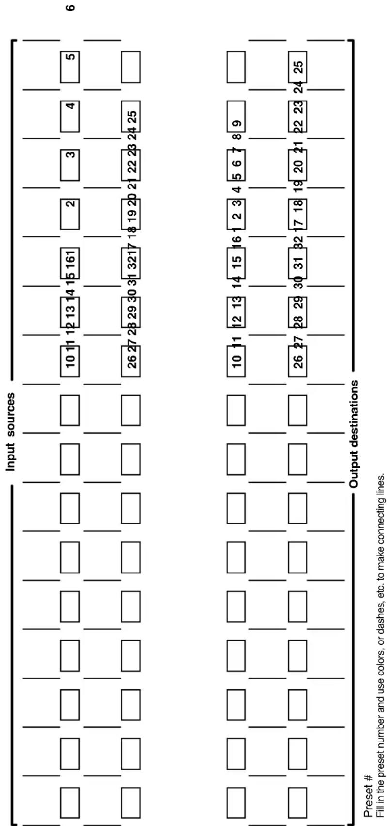
Preset #
Fill in the preset number and use colors, or dashes, etc. to make connecting lines.
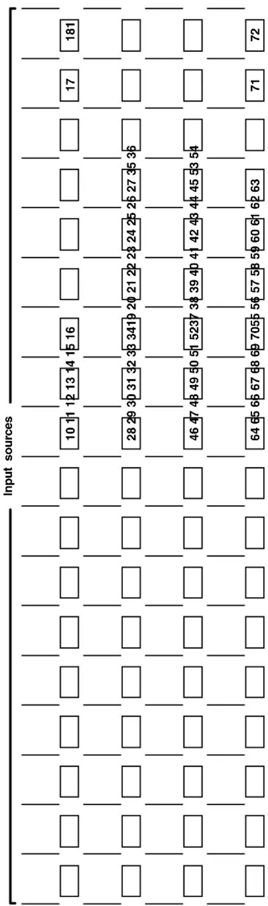
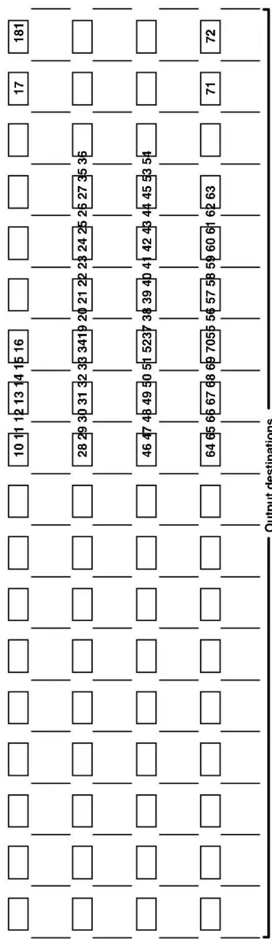
other
| Row | Column | Value | |---|---|---| | 1 | 1 | 10 11 12 13 14 15 16 | | 2 | 1 | 28 29 30 31 32 33 34 19 20 21 22 23 24 25 26 27 35 36 | | 3 | 1 | 46 47 48 49 50 51 52 37 38 39 40 41 42 43 44 45 53 54 | | 4 | 1 | 64 65 66 67 68 69 70 55 56 57 58 59 60 61 62 63 | | 5 | 1 | 71 | | 6 | 1 | 17 | | 7 | 1 | 181 | Output destinationsPreset #
Fill in the preset number and use colors, or dashes, etc. to make connecting lines.
Blank Configuration Worksheet, FOX Matrix 7200
Programming Guide
This section describes the operation of the FOX matrix switchers via SIS commands, including:
- Serial Ports
- Ethernet (LAN) Port
• Host-to-Switcher Instructions - Switcher-Initiated Messages
- Switcher Error Responses
• Using the Command and Response Tables
• Command and Response Table for SIS Commands
• Command Response Table for IP- and SNMP-Specific SIS Commands
• Special Characters
Serial Ports
The FOX matrix switcher has two serial ports that can be connected to a host device such as a computer running the HyperTerminal or DataViewer utility, or a control system. These ports make serial control of the switcher possible. The serial ports are:
- Rear panel Remote port — A 9-pin D connector for serial RS-232 or RS-422 control (see Remote port on page 13).
- Front panel Configuration port — A 2.5 mm mini stereo jack for serial RS-232 control (see Front Panel Configuration Port on page 17).
NOTES:
- The serial ports, the Remote port and the Configuration port, are independent of one another. A front panel Configuration port connection and a rear panel Remote port connection can be active at the same time. Commands are processed in the order received.
- The default serial port protocol of both ports is as follows:
9600 baud
No parity
8-bit
- No flow control
- 1 stop bit
- The rear panel Remote port can be configured from the front panel (see Selecting the Rear Panel Remote Port Protocol and Baud Rate, on page 42).
- The front panel Configuration port protocol can be changed via an SIS command only. See the Set serial port parameters SIS Command, on page 69, to configure both ports using an SIS command.
- The serial ports can be configured to operate at the 9600, 19200, 38400, or 115200 baud rate, but Extron recommends leaving these ports at 9600 baud only
Ethernet (LAN) Port
The rear panel Ethernet connector on the switcher can be connected to an Ethernet LAN or WAN. Communications between the switcher and the controlling device is via Telnet (a TCP socket using port 23). The SIS commands and the actions of the switcher are identical to the commands and actions the switcher has when communicating with it via RS-232.
The Ethernet cable can be terminated as a straight-through cable or a crossover cable and must be properly terminated for your application (see Ethernet Connection on page 13).
Default IP addresses
To access the FOX matrix switcher via the LAN port, you need the IP address for the unit, and may need the subnet mask and the gateway address. If the IP address has been changed to an address comprised of words and characters, you can determine the actual numeric IP address using the ping (ICMP) utility (see Ethernet Link on page 119 for more details). If the addresses have not been changed, the factory-specified defaults are:
• IP address 192.168.254.254
• Gateway address 0.0.0.0
- Subnet mask 255.255.0.0
Establishing a Connection
Establish a network connection to a FOX matrix switcher as follows:
- Open a TCP socket to port 23 using the IP address of the switcher.
NOTE: If the local system administrators have not changed the value, the factory-specified default, 192.168.254.254, is the value for this field.
The switcher responds with a copyright message including the copyright year, the name of the product, firmware version, part number, and the current date and time.
NOTES:
- The switcher is shipped password-protected. The factory configured passwords for all accounts on this device have been set to the device serial number.
- In the event of a complete system reset, the password converts to the default, which is no password. New passwords must be configured to secure the device.
- On password-protected connections, there are two levels of protection: administrator and user. Administrators have full access to all switching capabilities and editing functions. Users can create ties, create and recall presets, set mutes, and view all settings with the exception of passwords.
- If the switcher is not password-protected, the device is ready to accept SIS commands immediately after it sends the copyright message.
-
If the switcher is password-protected, a password prompt appears below the copyright message.
-
If the switcher is password protected, enter the appropriate administrator or user password.
If the password is accepted, the switcher responds with Login User or Login Administrator.
If the password is not accepted, the Password prompt reappears.
Connection Timeouts
The Ethernet link times out after a designated period of time of no communications. By default, this timeout value is set to five minutes but the value can be changed (see the Configure port timeout SIS commands on page 69).
NOTE: Extron recommends leaving the default timeout at 5 minutes and periodically issuing the SIS Q command (see Query firmware version SIS command on page 65) to keep the connection active. If there are long idle periods, Extron recommends disconnecting the socket and reopening the connection when another command must be sent.
Number of Connections
A FOX matrix switcher can have up to 200 simultaneous TCP connections, including all http sockets and telnet connections. When the connection limit is reached, the switcher accepts no new connections until some have been closed. No error message or indication is given that the connection limit has been reached. To maximize performance of an IP Link device, keep the number of connections low and close unnecessary open sockets.
Using Verbose Mode
Telnet connections to a FOX matrix switcher can be used to monitor for changes that occur on the switcher, such as front panel operations and SIS commands from other telnet sockets or a serial port. For a telnet session to receive change notices from the switcher, the telnet session must be in verbose mode 1 or 3 (see the Verbose Mode SIS command on page 69). In verbose mode 3, the telnet socket reports changes in messages that resemble SIS command responses.
Host-to-Switcher Instructions
The switcher accepts SIS commands through either serial port and the LAN port. SIS commands consist of one or more characters per command field. They do not require any special characters to begin or end the command character sequence. When a command is valid, the unit executes it and sends a response to the host device. Each switcher response to an SIS command ends with a carriage return and a line feed (CR/LF = ←), which signals the end of the response character string. A string is one or more characters.
Switcher-initiated Messages
When a local event such as a front panel operation or an IR 501 command string occurs, the switcher responds by sending a message to the host. The switcher-initiated messages are listed below (underlined).
The switcher does not expect a response from the host, but, for example, the host program might request a new status.
(C) COPYRIGHT 20yy, Extron Electronics, FOX Matrix 3200, Vx.xx, 60-nnnn-01← {day, date, time}
- or -
(C) COPYRIGHT 20yy, Extron Electronics, FOX Matrix 7200, Vx.xx, 60-nnnn-01← {day, date, time}
The switcher initiates the copyright message when it is first powered on or when a connection via Internet protocol (IP) is established. Vx.xx is the firmware version number and 60-nnnn-01 is the switcher part number.
NOTE: {Day, date, time} are only reported if the connection is via the LAN port.
Password:
The switcher initiates the password message immediately after the copyright message when the controlling system is connected using TCP/IP or Telnet and the switcher is password protected. This message means that the switcher requires an administrator or user level password before it will perform the commands entered via this link. The switcher repeats the password message response for every entry other than a valid password until a valid password is entered.
NOTE: The factory configured passwords for all accounts on this device have been set to the device serial number. Passwords are case sensitive.
←Login Administrator←
Login User
The switcher initiates the login message when a correct administrator or user password has been entered. If the user and administrator passwords are the same, the switcher defaults to administrator privileges.
Qik←
The switcher initiates the Qik message when a front panel tie operation has occurred.
Sprnn←
The switcher initiates the Spr message when a memory preset has been saved from the front panel. "nn" is the preset number.
Rprnn←
The switcher initiates the Rpr message when a memory preset has been recalled from the front panel. "nn" is the preset number.
Vmtnn*x←
The switcher initiates the Vmt message when a channel output mute is toggled on or off from the front panel. nn is the output number and x is the mute status: 1 = on, = off .
Exen
The switcher initiates the Exe message when the front panel security lockout (executive mode) is toggled on or off from the front panel. "n" is the lock mode: = unlocked , 1 = locked.
Switcher Error Responses
When the switcher receives an SIS command and determines that it is valid, it performs the command and sends a response to the host device. If the switcher is unable to perform the command because the command is invalid or contains invalid parameters, the switcher returns an error response to the host. The error response codes are:
E01 — Invalid input channel number (out of range)
E10 — Invalid command
E11 — Invalid preset number (out of range)
E12 — Invalid output number (out of range)
E13 — Invalid value (out of range)
E14 — Invalid command for this configuration
E17 — Timeout (caused only by direct write of global presets)
E21 — Invalid room number
E24 — Privileges violation (Ethernet only. Personnel logged in as users attempting operations requiring administrator privileges. Users have access to all view and read commands [other than the administrator password], and can create ties and presets, and mute and unmute the output.)
Using the Command and Response Tables
The command and response table begins on page 59. Symbols, defined on the next page and used throughout the table, represent variables in the command and response fields. Command and response examples are shown throughout the table. The SIS commands are not case sensitive unless specifically noted. The ASCII to Hex conversion table below is for use with the command and response table.
| ASCII to | Hex | Conversion Table | Esc | 1B | CR | ∅D | LF | ∅A | |||||||
| Space → | 20 | ! | 21 | " | 22 | # | 23 | $ 24 | % | 25 | & | 26 | ' | 27 | |
| ( | 28 | ) | 29 | * | 2A | + | 2B | , 2C | - | 2D | . | 2E | / | 2F | |
| ∅ | 30 | 1 | 31 | 2 | 32 | 3 | 33 | 4 34 | 5 | 35 | 6 | 36 | 7 | 37 | |
| 8 | 38 | 9 | 39 | : | 3A | ; | 3B | < 3C | = | 3D | > | 3E | ? | 3F | |
| @ | 40 | A | 41 | B | 42 | C | 43 | D 44 | E | 45 | F | 46 | G | 47 | |
| H | 48 | | | 49 | J | 4A | K | 4B | L 4C | M | 4D | N | 4E | O | 4F | |
| P | 50 | Q | 51 | R | 52 | S | 53 | T 54 | U | 55 | V | 56 | W | 57 | |
| X | 58 | Y | 59 | Z | 5A | [ | 5B | \ 5C] | 5D | ^ | 5E | - | 5F | ||
| ` | 60 | a | 61 | b | 62 | c | 63 | d 64 | e | 65 | f | 66 | g | 67 | |
| h | 68 | i | 69 | j | 6A | k | 6B | l 6C | m | 6D | n | 6E | o | 6F | |
| p | 70 | q | 71 | r | 72 | s | 73 | t 74 | u | 75 | v | 76 | w | 77 | |
| x | 78 | y | 79 | z | 7A | { | 7B | l 7C} | 7D | ~ | 7E | DEL | 7F | ||
Command and Response Table for SIS Commands
Symbol Definitions
← = CR/LF (carriage return with line feed) (hex ∅D ∅A)
← = Carriage return (no line feed, hex ∅D)
(| [Pipe] can be used interchangeably with the ← character)
Esc = Escape key (hex 1B)
• = Space character
(W can be used interchangeably with the Esc character)
[X1] = Input number (for tie)
∅∅ - 32 (FOX Matrix 3200) or 72 (FOX Matrix 7200) (∅∅ = untied)
X2 = Output number
∅∅ - 32 (FOX Matrix 3200) or 72 (FOX Matrix 7200) (∅∅ = untied)
X3 = Mute
= not muted 1 = muted
X4 = SFP or reclockable output number
∅∅ - 32 or 72 (∅∅ = global [SFP only])
X5 = Output reclocking rate 00 = Bypass mode
1^*=Auto(HDSDI boards)or N/A(laser boards)
03 = 2.125 Gbps (laser boards only)
∅2 = 1.250 Gbps (laser boards only)
04* = 4.250 Gbps (laser boards only)
X6 = Laser control
∅ = disable
1 = enable (default)
2 = automatic
X7 = Global preset #
- 32 (3200) or 72 (7200) ( = current configuration for view only)
[X8] = Room number (for room presets)
01 - 10 maximum (each can have up to 10 presets [X10] assigned)
NOTE: A Room is a subset of operator-selected outputs that relate to each other. The FOX matrix switcher supports up to 10 rooms, each of which can consist of 1 to 16 outputs.
X9 = Name
Up to 12 characters for input and output names and global and room preset names Upper- and lower-case alphanumeric characters and _ / and spaces are valid.
NOTE: The following characters are invalid or not recommended in the name: \~, @ = ' [ ] { } < > ' "; : | \ and ?.
X10 = Room preset number
∅1 - 1∅ maximum
NOTE: A Room preset is a stored configuration with all outputs in a single room. A retrieved room preset becomes the current configuration.
X11 = Connection status
∅ = no input connected
1 = input connected
X12 = Group number (for I/O grouping)
1 (group 1) through 4 (group 4) (or = no group)
X13 = Input number (for other than tie)
01 - 32 (FOX Matrix 3200) or 72 (FOX Matrix 7200)
X14 = Lock mode status
∅ = unlocked
1 = locked
X15 = Number (quantity) of inputs
8, 16, 24, 32, 40, 48, 56, 64, or 72
X16 = Number (quantity) of outputs
8, 16, 24, 32, 40, 48, 56, 64, or 72
X17 = Board installed
∅ = No board installed
4 = Non-pathological multimode board
X18 = I/O board slot number
1 = Non-reclocking multimode board ^t
5 = Non-pathological singlemode board
X19 = Transceiver module installed
2 = Non-reclocking singlemode board ^†
6 = Pathological singlemode board
3 = 3G, SDI, HD-SDI board
x = Unknown board or mix of transceivers
1 - 9 (FOX Matrix 7200) or 1 - 4 (FOX Matrix 3200)
X20 = Transceiver module number
∅ = No module installed
X21 = Vendor or manufacturer name
1 = Non-pathological multimode module
3 = 3G-SDI, HD-SDI, SD-SDI module
2 = Non-pathological singlemode module
4 = Pathological singlemode module
X22 = Transmit output power in milliwatts
X23 = Receive optical power in milliwatts
X24 = SFP temperature
Degrees Celsius
X25 = Firmware version number to second decimal place (x.xx)
X26 = Verbose firmware version-description-upload date and time. See the Query controller firmware version (verbose) command on page 65.
X27 = Voltage
Positive or negative voltage and magnitude
X28 = Switcher temperature
Degrees Fahrenheit
X29 = Fan speed
In revolutions per minute (RPM)
* 01 is default for HDSDI boards, 04 is default for laser boards.
^† Legacy board, no longer manufactured, identified for completeness only.
Command and Response Table for SIS Commands
| Command Function SIS Command (Host to Unit) | Response (Unit to Host) | Additional description | |
| NOTES:The matrix switchers support 1- and 2-digit numeric entries (1*1 or 02*02).Commands can be entered back-to-back in a string, with no spaces. For example: 1*1!02*02&03*03%4*8!. | |||
| Create ties | |||
| NOTES:The quick multiple tie and tie input to all output commands activate all I/O switches simultaneously.The !tie command, &tie command, and %tie command can be used interchangeably.The !tie all command, &tie all command, and %tie all command can be used interchangeably.When you create a tie whereX1=00, you tie no input to the specified output(X2)(untieX2).When you create a tie whereX2=00, you untie all outputs from inputX1. | |||
| Tie inputX1to outputX2,Example: | X1*X2! Out | X2•InX1•All← | Tie inputX1to outputX2. |
| 1*3! | Out03•In01•All← | Tie input 1 to output 3. | |
| Tie inputX1to outputX2,Example (see 2nd Note bullet, above): | X1*X2& Out | X2•InX1•RGB← | Tie inputX1to outputX2. |
| 10*4& | Out04•In10•RGB← | Tie input 10 RGB to output 4. | |
| Tie inputX1to outputX2X1Example (see 2nd Note bullet, above): | *X2% Out | X2•InX1•Vid← | Tie inputX1to outputX2. |
| 7*5% | Out05•In07•Vid← | Tie input 7 video to output 5. | |
| Quick multiple tieExample: | Esc+Q[X1*X2!...X1*X2&← | Qik← | |
| Esc+Q3*4!3*5%3*6&← | Qik← | Tie input 3 to output 4, tie input 3 to output 5, and tie input 3 to output 6. | |
| Tie input to all outputsExample (see last Note bullet, above): | X1*! In | X1•All← | |
| 5*! | In05•All← | Tie input 5 to all outputs. | |
| TIP: 0*! clears all ties. | |||
| Tie input to all outputsExample (see last Note bullet, above): | X1*& In | X1•RGB← | |
| 8*& | In08•RGB← | Tie input 8 to all outputs. | |
| Tie input to all outputsExample (see last Note bullet, above): | X1*% In | X1•Vid← | |
| 10*% | In10•Vid← | Tie input 10 to all outputs. | |
| Read ties | |||
| NOTES:The !read tie command, &read tie command, and %read tie command can be used interchangeably.When the switcher is in verbose mode, the response is Out X2•InX1•(All)(RGB) or (Vid)←. | |||
| Read tied input | X2! | X1← | InputX1is tied to outputX2. |
| Read tied input, RGB output | X2& | X1← | InputX1is tied to outputX2. |
| Read tied input, Vid output | X2% | X1← | InputX1is tied to outputX2. |
| Channel mute commands | |||
| Channel mute | X2*1B Vmt | X2*1← | Mute outputX2channel (no signal is output, but the light output remains active). |
| Channel unmute | X2*0B Vmt | X2*0← | Unmute outputX2channel (signal is output). |
| Read channel mute | X2B | X3← | 1 = mute on, 0 = mute off. |
| Global channel mute | 1*B | Vmt1← | Mute all output channels. |
| Global channel unmute | 0*B | Vmt0← | Unmute all output channels. |
| KEY:X1= Input number (for tie)00-(maximum number of inputs for your configuration) (00= untied)X2= Output number00-(maximum number of outputs for your configuration) (00= untied)X3= Mute 0= not muted, 1=mutedReclocking | |||
| NOTES:• Laser board reclockers are set on a per SFP basis. If an SFP is reclocked, the corresponding input and output reclockers reclock at the same rate.• HD-SDI reclockers are set on a per output basis only.• If the connected input or output device is a FOX USB Extender unit, ensure that the reclockers are set to bypass mode. | |||
| Set output reclocker | X4*X5= Rte | X4*X5← | Set the rate for reclocker X4 to X5. |
| Example: | 8*00= | Rte08*00← | Set the rate for reclocker 8 to bypass. |
| Read reclocker status | X4= | X5← | Show current rate status for reclocker X4. |
| Laser controls | |||
| Enable individual laser driver | EscX2*1FIBR← | FibrX2*1← | Enable the laser for output X2. The laser lights so long as power is applied. |
| Disable individual laser driver | EscX2*0FIBR← | FibrX2*0← | Disable the laser for output X2. The laser is off. |
| Set individual output laser driver to automatic | EscX2*2FIBR← | FibrX2*2← | Set the laser driver for output X2 to automatic. The laser lights when a tie is made to output X2, but is off when no tie is made to output X2 or the output is muted. |
| Read status of all laser drivers | EscFIBR← | X6 X6 X6 X6 ... X6← | List the laser driver status of all installed outputs.n is the highest numbered output for your switcher. |
| Global laser enable | Esc1*FIBR← | Fibr1← | Enable all output laser drivers. |
| NOTE: If your switcher has any BNC 3G/HD/SD-SDI boards installed, the global commands are not available. The switcher returns E14. | |||
| Global laser disable | Esc∅*FIBR← | Fibr∅← | Disable all output laser drivers. |
| Global laser automatic | Esc2*FIBR← | Fibr2← | Set all output laser drivers to automatic. |
| Save, recall, and directly write global presets | |||
| NOTES:• If you try to recall a preset that is not saved, the matrix switcher responds with the error code E11.• The following characters are invalid or not recommended in preset names: + - , ` @ = [ ] { } ‘ “ ; : | \ and ?. | |||
| Save current configuration as a global preset | X7, Spr | X7← | Command character is a comma. |
| Example: | 8, | Spr∅8← | Save current ties as preset 8. |
| Recall a global preset | X7. Rpr | X7← | Command character is a period. |
| Example: | 5. | Rpr∅5← | Recall preset 5 (becomes the current configuration). |
| KEY: X1 = Input number (for tie) ∅0 - (maximum number of inputs for your configuration) (∅0 = untied)X2 = Output number ∅1 - (maximum number of outputs for your configuration)X4 = SFP or reclockable output ∅0 - 32 or 72 (∅0 = global [SFP only])X5 = Output reclocking rate ∅0 = Bypass mode∅1 = Automatic mode (HDSDI [default] only) or N/A (laser) ∅3 = 2.125 Gbps (laser only)∅2 = 1.250 Gbps (laser boards only) ∅4 = 4.250 Gbps (laser only [default])X6 = Laser control ∅ = disable 1 = enable (default) 2 = automaticX7 = Global preset number ∅0 - 32 (FOX Matrix 3200) or 64 (FOX Matrix 7200) (∅0 = current configuration) | |||
| Save, recall, and directly write global presets (continued) | |||
| Direct write process — | |||
| NOTE: The direct write of a global preset should always be preceded by a clear global preset ties command of that same preset number. In a directly-written preset, the tied input of each output position (or no tied input) remains unchanged unless overwritten or cleared. If you do not clear the ties in a global preset number before you directly write a global preset to that number, ties that are part of the previous version of the specified preset with the same number can unexpectedly become part of the newly-created preset. | |||
| Clear global preset ties | Esc+X7P0*!← | SprX7← | Clear all ties in preset X7. |
| Directly write a global preset | Esc+X7P1*X2!X1*X2%X1*X2! | ...X1*X2&← | Enter as many ties as are valid for this configuration. The ! tie, & tie, and % tie commands are all valid. |
| SprX7← | |||
| Example: | Esc+27P0*!← | Spr27← | Clear all ties in preset 27. |
| Esc+27P12*5↓10*09%3*2!3*8&← | Spr27← | Brackets are shown to separate ties for clarity only. Create global preset 27, which ties input 12 to output 5, input 10 to output 9, input 3 to output 2, and input 3 to output 8. | |
| NOTES:If a room is not defined (does not exist in the switcher), the matrix switcher responds with the error code E11.A room can contain a maximum of 16 outputs (X2s).An output can belong to only one room.The maximum number of rooms (X8s) is 10.The default name (X9) is the room number with four trailing spaces: “Room•#X8•••” | |||
| Write room outputs | EscX8,X2,X2',...X2*MR← | MprX8,X2,X2',...X2'← | See the notes above. |
| Example: | Esc8,3,04,5,6MR← | Mpr8,03,04,05,06← | Outputs 3, 4, 5, and 6 are assigned to room 8. |
| Read room outputs | EscX8MR← | X9,X2,X2',...X2'← | |
| Example: | Esc3MR← | Class1,01,02,08,09← | Outputs 1, 2, 8, and 9 are assigned to room 3, which is named “Class1”. |
| Save current ties as a room preset | X8'X10, | RmmX8•SprX10← | Command character is a comma. |
| Example: | 3*9, | Rmm03•Spr09← | Save current ties as preset 9 for room 3. |
| Recall room preset | X8*X10, Rmm | X8•RprX10← | Command character is a period. |
| Clear room preset ties | Esc+X8*X10P0*!← | RmmX8•SprX10← | Clear all ties in room X8preset X10. |
| Directly write a room preset | Esc+X8*X10P1*X2!X1*X2%X1*X2! ... X1*X2K← | RmmX8•SprX10← | Enter as many ties as are valid for this configuration. The ! tie command, & tie, and % tie commands are all valid and equivalent. |
| Example: | Esc+7*3P12*7&11*5!4*5%6*6← | Rmm07•Spr03← | Brackets are shown to separate ties for clarity only. Create preset 3 for room 7, which ties input 12 to output 7, input 11 to output 5, input 4 to output 5, and input 6 to output 6. |
| View ties, mutes, and presets | |||
| NOTE: The & read tie command and % read tie command can be used interchangeably. | |||
| View output tie | X2! | X1← | Input X1 is tied to output X2. |
| Example: | 1! | 05← | Input 5 is tied to output 1. |
| View output tie | X2& | X1← | |
| Example: | 15& | 27← | Input 27 is tied to output 15. |
| View output tie | X2% | X1← | |
| Example: | 7% | 02← | Input 2 is tied to output 7. |
| KEY: X1 = Input number (for tie) 00 - (maximum number of inputs for your configuration) (00 = untied)X2 = Output number 01 - (maximum number of outputs for your configuration)X7 = Global preset number 00 - 32 (FOX Matrix 3200) or 64 (FOX Matrix 7200) (00 = current configuration)X8 = Room number (for room presets) 01 - 10 maximum (each can have up to 10 presets (X10) assigned)X9 = Room name 12 characters maximumX10 = Room preset number 01 - 10 maximum | |||
| View ties, mutes, and presets (continued) | |||
| View all output mute status EscVM← | X31X32X33... X3?← | Each X3 response is the mute status of an output, starting from output 1. n is the highest-numbered output. | |
| NOTES:The switcher reports the mute status for all outputs, up to the highest numbered output on the highest numbered slot with an I/O board installed. The switcher does not recognize gaps in the board installation. For example, if boards are installed in only slots 1 and 3, leaving slot 2 empty, the switcher returns mute status for 24 sequential outputs. The mute status for the outputs in slot 2, inputs 9 through 16, can be ones or zeroes (the switcher allows you to mute an output that is not installed, so long as it is numbered lower than the highest numbered output installed).When the switcher is in Verbose mode 1 or 3 (see the Set verbose mode SIS command on page 69), the response includes “Mut” before the X3s. | |||
| View global preset configuration EscX7*X2*1VC← | X11-X1+1•...X1-15•Vid← | Show the configuration of preset X7. Show the input tied to 16 sequential outputs, starting from output X2. | |
| Command description: preset # (X7)*starting output # (X2)*1VC← | |||
| Response description: input # (X1) tied to X2•X1 tied to X2+1•X1 tied to X2+2• ... •X1 tied to X2+15•Vid← | |||
| Example (8 x 8 matrix): Esc23*1*1VC← | |||
| Input 8 tied to output 4 | |||
| input 2 tied to output 3 | |||
| Response = tied input:08•08•02•08•08•01•00•00•00•00•00•00•00•00•00•00•00•00•00•00•00•00•00•00•00•00•00•00•00•00•00•00•00•00•00•00•00•00•00•00 | no tied input outputs do not exist | ||
| 1Output: 3 4 5 6 7 8 13 14 15 1609 10 11 12 | |||
| Each position shown in the response is an output: left = starting output number (1 in this example), right = starting output number + 15 (16 in this example). (Outputs 9 through 16 are not present on this matrix switcher.) The number in each position is the input tied to that output. | |||
| In this example, for preset 23, video input 8 is tied to outputs 1, 2, 4, and 5; input 2 is tied to output 3; and input 1 is tied to output 6. No inputs are tied to outputs 7 and 8. | |||
| NOTE: EscX7*1*X2VC← where X7 = 0 returns 16 ties in the current video configuration of the switcher, starting from output X2 | |||
| View room preset EscX8*X10*X2*1VC← | X11-X1+1•...X1-15•Vid← | Show configuration of room X8, preset X10. Show the input tied to up to 16 outputs assigned to room X8. | |
| Configuration | |||
| Command description: room # (X8)*room preset # (X10)*starting output # (X2*1VC | |||
| Response description: input # (X1) tied to X2•X1 tied to X2-1•X1 tied to X2-2• ... •X1 tied to X2-15•Vid← | |||
| List input link detection | |||
| NOTE: The switcher reports the link status for all outputs, up to the highest numbered output on the highest numbered slot with an I/O board installed. The switcher does not recognize gaps in the board installation. For example, if only two boards are installed, in slots 1 and 3, leaving slot 2 empty, the switcher returns link status for 24 sequential inputs. The input link response for the inputs supported by the board in slot 2, inputs 9 through 16, are all zeroes. | |||
| View all input connections 0LS | X11 X11 X11 X11 ... X11← | Each X11 response is the connection status of an input, starting from input 1.n is the highest-numbered input. | |
| Example (32 x 32 matrix): 0LS | no input detected input detected | ||
| Response Status: 0001110..0← | |||
| Input: 1234567 3 : | |||
| KEY: X1 = Input number (for tie) 00 - (maximum number of inputs for your configuration) (00 = untied)X2 = Output number 01 - (maximum number of outputs for your configuration)X3 = Mute 0 = not muted, 1 = mutedX7 = Global preset number 00 - 32 (FOX Matrix 3200) or 64 (FOX Matrix 7200) (00 = current configuration for view only)X8 = Room number (for room presets) 01 - 10 maximum (each can have up to 10 presets X10) assigned)X10 = Room preset number 01 - 10 maximumX11 = Connection status 0 = no input connected 1 = input connected | |||
| I/O grouping | |||
| NOTE: The group that is assigned in each of the following I/O grouping commands (X12 must be 1, 2, 3, 4, or ∅ (not grouped). | |||
| Write input grouping | EscX12 X122...X127I← | GriX12 X123...X127← | Each X12 entry is the group number assigned to an input, starting from input 1.n is the highest-numbered input. |
| Example (16 x 16 matrix): | Esc40133000044...4I← | See below. Input 1 is in Group 4,Input 1 in group 4. Input 2 not grouped Input 16 in group 4 | Input 2 is in Group 0 (not grouped), ... |
| Response #s = group: Gri 40133000044...4I← | 40133000044...4I← | Input 16 is in Group 4. | |
| Write output grouping | EscX12 X122...X127O← | GroX12 X123...X127← | Each X12 entry is the group number assigned to an output, starting from output 1.n is the highest-numbered output. |
| Read input grouping | EscI←X12 | X12 X123...X127← | Each X12 entry is the group number assigned to an input, starting from input 1.n is the highest-numbered input. |
| Example (8 x 8 matrix): | EscI← | Input 1 in group 1. Input 8 not groupedResponse = group: 111330000000000000000000000000000000000000000000000000000000000000000000000000000000000000000000000000000 | n is the highest-numbered output. |
| Read output grouping | EscO←X12 | X12 X123...X127← | Each X12 entry is the group number assigned to an output, starting from output 1.n is the highest-numbered output. |
| Names | |||
| NOTES:The HTML language reserves certain characters for specific functions (see Special Characters on page 70).Do not use leading spaces in preset names.If a preset is unassigned, the name X9 displays [unassigned].If a global preset is saved, but not yet named, the default name is Preset X7If a room preset is saved, but not yet named, the default name is Rm X8 Prst X10. | |||
| Write global preset name | EscX7,X9NG← | NmgX7,X9← | |
| Example: | Esc1,Security 1NG← | Nmg∅1,Security 1← | Name global preset 1 “Security 1”. |
| Read global preset name | EscX7NG←X9← | ||
| Example: | Esc2NG← | Security 2← | Global preset 2 is named “Security 2”. |
| Write room preset name | EscX8*X10,X9NP← | NmpX8*X10,X9← | |
| Example: | Esc1*3,Podium_DVDNP← | Nmp∅1*3,Podium_DVD← | Name room 1, preset 3 “Podium_DVD”. |
| Read room preset name | EscX8*X10NP←X9← | ||
| Write input name | EscX13,X9NI← | NmiX13,X9← | |
| Example: | Esc1,Podium camNI← | Nmi∅1,Podium cam← | Name input 1 “Podium cam”. |
| Read input name | EscX13NI←X9← | ||
| Write output name | EscX2,X9NO← | NmoX2,X9← | |
| Example: | Esc1,Main PJ1NO← | Nmo∅1,Main PJ1← | Name output 1 “Main PJ1”. |
| Read output name | EscX2NO←X9← | ||
| KEY:X2= Output number∅1-(maximum number of outputs for your configuration)X7= Global preset number∅0-32 (FOX Matrix 3200) or 64 (FOX Matrix 7200) (∅∅= current configuration)X8= Room # (for room presets)∅1-10 (each can have up to 10 presets (X9s) assigned)X9= Room name12 characters maximumX10= Room preset number∅0-10 maximum (0 = current configuration for room)X12= Group number (for I/O grouping)1 (group 1) through 4 (group 4) (or ∅ = no group)X13= Input number (for other than tie)∅1-(maximum number of inputs for your configuration)Front panel lockout (Executive mode) | |||
| Lock front panel | 1X | Exe1← | Enable executive mode. |
| Unlock front panel | 0X | Exe0← | Disable executive mode. |
| View lock status | X | X14← | |
| Resets | |||
| Reset global presets and names | EscZG← | Zpg← | Clear all global presets and their names. |
| Reset one global preset | EscX7ZG← | ZpgX7← | Clear global preset X7 |
| Reset all mutes | EscZZ← | Zpz← | Unmute all outputs. |
| Reset room map | EscZR← | Zpr← | Clear all room definitions. |
| Reset individual room | EscX8ZR← | ZprX8← | Delete room X8 |
| Reset all room presets | EscZP← | Zpp← | Clear all room presets and names. |
| Reset individual room preset | EscX8*X10ZP← | ZppX8*X10← | Clear an individual room preset and name. |
| Reset whole switcher | EscZXXX← | Zpx← | Clear all ties and presets, rooms, and I/O names. |
| Absolute reset | EscZQQQ← | Zpq← | Similar to Reset whole switcher, above, plus clear the IP address to 192.168.254.254 and subnet mask to 255.255.000.000. |
| NOTE: The factory configured passwords for all accounts on this device have been set to the device serial number. In the event of a complete system reset, the passwords convert to the default, which is no password (see the Set administrator password SIS command on page 68 to change the password). | |||
| Reset all device settings | EscZY← | Zpy← | Similar to absolute reset, above, but excludes the following IP settings: IP address, subnet mask, gateway address, unit name, DHCP setting, and port mapping (telnet, web, and direct address). |
| File management | |||
| NOTE: The response to the View File Directory command differs, depending on whether the command is sent via an RS-232/RS-422 or Telnet connection or sent via a web browser connection. | |||
| View file directoryRS-232/RS-422 port and Telnet | EscDF← | filename1, date and time, length←filename2, date and time, length←filename3, date and time, length←······...filenamen, date and time, length←# of Bytes•Left←List user-supplied files. | |
| View file directoryWeb browser | EscDF← | Var file = new array ();File [1] = 'filename1, date1, filesize1';File [2] = 'filename2, date2, filesize2';File [3] = 'filename3, date3, filesize3';······...File [n] = 'filenamen, daten, filesizen';File [n+1] = # of Bytes•LeftList user-supplied files. | |
| Erase user-supplied web pages or files | EscEF← | Del← | |
| KEY: X7 = Global preset number ∅1 - 32 (FOX Matrix 3200) or 64 (FOX Matrix 7200)X8 = Room # (for room presets) ∅1 - 10 (each can have up to 10 presets (X9s) assigned)X10 = Room preset number ∅1 - 10 maximumX14 = Lock mode status ∅ = unlocked 1 = lockedInformation requests | |||
| Information request | I | V X15 X16 • A X15 X16 • S X17 X17 | X17 |
| V X15 X16 shows the number of available inputs and outputs for this configuration. A X15 X16 has no meaning for this product. S X17 X17 ... X17 shows the board type installed in each slot. n is either 4 or 9, depending on the model. | |||
| Slot, plane, and LC information | 0 * X18 I | X19 X19 X19 X19 X19 X19 X19 X19 | X19 |
| Request part number | N | 60 -nnnn -nn | See www.extron.com, for part numbers. |
| Request part number and board configuration | *N | 60 -nnnn -nn, X17 X17 X17 | X17 |
| Part number (see below) plus I/O boards installed. n is either 4 or 9, depending on the model. | |||
| Read reclocker status | X4= | X5 | Show current rate status for reclocker X4. |
| NOTE: The switcher automatically detects and reclocks the signal if the rate is 4.25 Gbps only. Other rates are ignored. | |||
| View SFP module status | 40 * X20 S | X21 • X22 • X23 • X24 | |
| NOTE: There are up to three separate sets of Extron firmware on which the switcher can report: the controller firmware, which is the overall control firmware; the Ethernet protocol firmware, which handles the Ethernet interface; and the latest optional Extron firmware update, which is available at www.extron.com. | |||
| Query firmware version | Q | X25 | |
| Example: | Q | 1.23 | The factory-installed controller firmware version is 1.23 (sample value only). |
| Query controller firmware version (verbose) | ∅Q | X25 -X26 - X26 | Provide a detailed status of the Ethernet protocol firmware, the controller firmware, and any firmware upgrade. The firmware that is running is marked by an asterisk (*). A caret (^) indicates that the firmware has a bad checksum or an invalid load. ???? indicates that firmware is not loaded. |
| Response description: | Ethernet protocol firmware version-controller firmware version-updated firmware version | ||
| Example: | ∅q | ||
| Description | * indicates the version running Upload date and time | ||
| 1.23-1.00(1.68-FOMX Series -Wed, 20 Feb 2008 00:00:00 GMT),1.00* (1.06-FOMX Series -Mon, 17 Mar 2007 16:39:21 GMT) | |||
| Ethernet protocol firmware | Fiber Matrix firmware version Updated firmware version | ||
| KEY: | X4 = SFP or reclockable output number | 1 - 32 or 72 | |
| X5 = Output reclocking rate = Bypass mode | |||
| 1 = Automatic mode (HDSDI boards only) | 3 = 2.125 Gbps (laser boards only) | ||
| 2 = 1.250 Gbps (laser boards only) | 4 = 4.250 Gbps (laser boards only) | ||
| X15 = Number (quantity) of inputs | 8, 16, 24, 32, 40, 48, 56, 64, or 72 | ||
| X16 = Number (quantity) of outputs | 8, 16, 24, 32, 40, 48, 56, 64, or 72 | ||
| X17 = Board installed | = No board installed | 4 = Non-pathological multimode board | |
| 1 | = Non-reclocking multimode board | 5 = Non-pathological singlemode board | |
| 2 = Non-reclocking singlemode board | 6 = Pathological singlemode board | ||
| 3 | = 3G, SDI, HD-SDI board | X = Unknown board or mix of transceivers | |
| X18 = I/O board slot number | 1 – 9 (FOX Matrix 7200) or 1 – 4 ( FOX Matrix 3200) | ||
| X19 = Transceiver module installed | = No module installed | ||
| 1 | = Non-pathological multimode module | 3 = 3G-SDI, HD-SDI, SD-SDI module | |
| 2 | = Non-pathological singlemode module | 4 = Pathological singlemode module | |
| X20 = Transceiver module number | 1 - 72 (or maximum number of transceiver modules for your configuration) | ||
| X21 = Vendor or manufacturer name | |||
| X22 = Transmit output power in milliwatts | |||
| X23 = Receive optical power in milliwatts | |||
| X24 = SFP temperature | Degrees Celsius | ||
| X25 = Firmware version number to second decimal place (x.xx) | |||
| X26 = Verbose firmware version-description-upload date and time (see above. | |||
| Command Function SIS Command (Host to Unit) | Response (Unit to Host) | Additional description | |
| Information requests (continued) | |||
| Request system status | S | ||
| FOX Matrix 3200 Response: | X27•X27•X27•X27•X27•X27•X28•X29•X29← | ||
| FOX Matrix 7200 Response: | X27•X27•X27•X27•X27•X27•X28•X29•X29•X29← | ||
| Response description (FOX Matrix 3200): | |||
| +3.3V•+5V•+1.3V•+1.2V•+12V (fan volts)•+12V (redundant PS)•+12V (primary PS)•Temp•Fan 1 RPM•Fan 2 RPM← | |||
| Response description (FOX Matrix 7200): | |||
| +3.3V•+5V•+1.3V•+1.2V•+12V (fan volts)•+12V (redundant PS)•+12V (primary PS)•Temp•Fan 1 RPM•Fan 2 RPM•Fan 3 RPM•Fan 4 RPM← | |||
| Backplane receiving 12.00 V | Internal temperature 80.6" F | ||
| Example (Matrix 3200): | S | 3.27•4.95•1.28•1.22•12.00•12.06•12.12•+080.60•03013•02860← | |
| 3.3 V power system at 3.27 V | Fan 1 rotating at 3,013 RPM | ||
KEY: X27 = Voltage Positive or negative voltage and magnitude X28 = Switcher temperature Degrees Fahrenheit X29 = Fan speed In revolutions per minute (RPM)
Command and Response Table for IP- and SNMP-Specific SIS Commands
Symbol definitions
X40 = Matrix name (Up to 24 alphanumeric characters)
NOTE: The HTML language reserves certain characters for specific functions (see Special Characters on page 70).
X41 = Default name Matrix 3200 - FOX-Matrix-3200 - + last 3 pairs of MAC address Matrix 7200 - FOX-Matrix-7200 - + last 3 pairs of MAC address
X42 = Time and date (for set) In the format: MM/DD/YY•HH:MM:SS where: MM = month: 01 (January) through 12 (December) DD = day: 01 through 31 YY = year: 00 through 99 HH = hour: 00 through 23 MM = minutes: 00 through 59 SS = seconds: 00 through 59
X43 = Time and date (for read) In the format: Day, •DD•Mmm•YYYY•HH:MM:SS where: Day = weekday: Mon through Sun DD = date: 01 through 31 Mmm = month: Jan through Dec YYYY = year: 2000 through 2099 HH = hour: 00 through 24 MM = minutes: 00 through 59 SS = seconds: 00 through 59
[X44] = GMT offset -12.0 through +14.0. Hours and minutes removed from GMT
45 = Daylight Saving Time = Daylight Saving Time off or ignore 2 = Daylight Saving Time on (Europe) 1 = Daylight Saving Time on (North America) 3 = Daylight Saving Time on (Brazil)
46 = IP address ####.###.###.### 47 = Hardware (MAC) address ##-##-##-##-##-## 48 = Number of open connections - 255 49 = Password 12 alphanumeric
NOTES:
- The factory configured passwords for all accounts on this device have been set to the device serial number. In the event of a complete system reset, the passwords convert to the default, which is no password.
• The HTML language reserves certain characters for specific functions (see Special Characters on page 70).
[X50] = Domain name Standard domain name rules apply (for example: xxx.com)
NOTE: The HTML language reserves certain characters for specific functions (see Special Characters on page 70). The @character is acceptable only as the lead-in to the domain name (such as @extron.com).
X51 = Email account 1 through 5 65 - 69. 65 = email recipient 1, 66 = 2, 67 = 3, ... 69 = recipient 5
X52 = Email address Typical email address format (for example: nnnn@xxx.com)
X53 = Notification selections, part 1 I = inputs F = fans P = power supply
54 = Notification selections, part 2 If 53 = I, then 54 = 00 (all inputs), or 01 through 32 (72) (input 1 through 32 [72])
If 53 = F , then 54 = (all fans)
If 53 = P , then 54 = (both power supplies).
55 = Notify when? = no response 1 = fail or missing 2 = fixed or restored 3 = both 1 & 2 4 = suspend
X56 = DHCP and SNMP ∅ = off or disable 1 = on or enable
[X57] = Port # ∅∅ (all ports), ∅1 (rear panel), ∅2 (front panel), ∅3 - 99
X58 = Baud rate 9600, 19200, 38400, 115200
[X59] = Parity odd, even, none, mark, space (Only the first letter required.)
60 = Data bits 7,8 61 = Stop bits 1,2 62 = Port type = RS-232 1 = RS-422
X63 = Verbose mode
∅ = clear or none (default for Telnet connection)
2 = tagged responses for queries
1 = verbose mode (default for RS-232/RS-422)
3 = verbose mode and tagged for queries
NOTE: If tagged responses are enabled, all read commands return the constant string and the value as the set command does (for example, the read matrix name command, EscCN← returns Ipn•x40←).
X64 = Port timeout (10-sec. increments) 1 (= 10 seconds) - 65000 (default is 30 = 300 seconds = 5 minutes)
X65 = SMNP port number 00000 (= disable) - nnnnn. Default = 00161. Leading zeroes are not necessary for entry.
X66 = SNMP contact name and location Up to 64 alphanumeric characters. Default = Not•Specified.
X67 = SNMP community name Up to 64 alphanumeric characters.
Default = public (for read community) or private (for read-write community).
X68 = Trap target 1 - 3
X69 = SNMP trap version 2 or 3, or 0 = empty (default) if no target set
X70 = SNMP target 1 through 3 70 - 72. 70 = SNMP target 1, ... 72 = target 3
Command and Response Table for IP- and SNMP-Specific SIS Commands
| Command Function | SIS Command (Host to Unit) | Response (Unit to Host) | Additional description |
| IP setup commands | |||
| Set matrix name | EscX40CN← | Ipn•X40← | |
| Read matrix name (location) | EscCN←X40← | ||
| Reset matrix name to factory default | Esc•CN← | Ipn•X40← | "FOX-Matrix-3 (7)-" plus the last 3 pairs of the MAC address. |
| Set time and date | EscX42CT← | IptX42← | |
| Read time and date | EscCT←X43← | ||
| Set GMT offset | EscX44CZ← | IpzX44← | In the command, the divider between hours and minutes can be either a colon or a period. In the response, the divider is a colon. |
| Example: | Esc8.3CZ← | Ipz+08:30← | 8.3 = 8:30 |
| Read GMT offset | EscCZ←X44← | ||
| Set Daylight Saving Time | EscX45CX←X45← | ||
| Read Daylight Savings Time | EscCX←X45← | ||
| Set IP address | EscX46CI← | IpiX46← | |
| Read IP address | EscCI←X46← | ||
| Read hardware address | EscCH←X47← | Reads MAC address. | |
| Read # of open connections | EscCC←X48← | ||
| Set subnet mask | EscX46CS← | IpsX46← | |
| Read subnet mask | EscCS←X46← | ||
| Set gateway IP address | EscX46CG← | IpgX46← | |
| Read gateway IP address | EscCG←X46← | ||
| Set administrator password | EscX49CA← | Ipa•X49← | |
| NOTES:The factory configured passwords for all accounts on this device have been set to the device serial number.In the event of a complete system reset, the password reverts to the default, which is no password. | |||
| Read administrator password | EscCA←X49← | ||
| Reset (clear) administrator password | Esc•CA← | Ipa•← | |
| Set user password | EscX49CU← | Ipu•X49← | |
| Read user password | EscCU←X49← | ||
| Reset (clear) user password | Esc•CU← | Ipu•← | |
| Set mail server, domainname | EscX46,X50,X49CM← | IpmX46,X50,X49← | |
| Read mail server, domainname | EscCM←X46 | ,X50,X49← | |
| IP setup commands (continued) | |||
| Set email recipient | EscX51,X52CR← | IprX51,X52,← | This command sets the email recipient. To receive email notifications, you must then set the events that the switcher reports, using one or more separate Set email (EM) SIS commands below). |
| Example: | Esc69,Jsmith@folklore.netCR← | Ipr69,Jsmith@folklore.net,← | |
| Read email recipient | EscX51CR←X52 | ,← | |
| Set email events for recipient | EscX53X51,X54,X55,0EM← | IpeX53X51*X54*X55*0← | You must first have set an email recipient for the X51 variable, using the separate Set email recipient (CR) command above. |
| Example: | EscI69,63,3,0EM← | IpeI69*63*3*0← | Email account #69 (recipient #5, JSmith), will receive fail or missing and fixed or restored messages for input 63. |
| Read email notifications for one account (recipient) | EscX53X51,X54,0EM←X55X55X55 | ...X55← | |
| Set DHCP on or off | EscX56DH← | IdhX56←X56 | :0 = off, 1 = on |
| Read DHCP on or off status | EscDH←X56← | ||
| Set serial port parameters | EscX57*X58,X59,X60,X61CP← | CprX57•CcpX58,X59,X60,X61← | |
| Read serial port parameters | EscX57CP←X58 | ,X59,X60,X61← | |
| Set serial port mode | EscX57*X62CY← | CprX57•CtyX62←X62 | :0 = RS-232, 1 = RS-422 |
| Read serial port mode | EscX57CY←X62← | ||
| Set verbose mode | EscX63CV← | VrbX63← | |
| Read verbose mode | EscCV←X63← | ||
| Configure current port timeout | Esc0*X64TC← | Pti0*X64← | |
| Read current port timeout | Esc0TC←X68← | ||
| Configure global IP port timeout | Esc1*X64TC← | Pti1*X64← | |
| Read global IP port timeout | Esc1TC←X68← | ||
SNMP setup commands
NOTE: See SNMP Settings Page, on page 105. This HTML page provides introductory information about Simple Network Management Protocol (SNMP) and is the preferred method for performing the functions listed below.
Port mapping
| Map SNMP port | EscA × 65PMAP← | PmapA × 65← | Assign a specific port. Default:161. |
| Reset SNMP port to default | EscA161PMAP← | PmapA00161← | |
| Disable SNMP port | EscA0PMAP← | PmapA00000← | Assign no port for SNMP.Assign a valid port to enable. |
| View current SNMP port | EscAPMAP←X65← |
Unit contact name and location
NOTE: No contact or location (as opposed to Not•Specified, the default value) is not a valid entry.
| Set unit contact info | EscC X66 SNMP← | SnmpC* X66← | Set contact info to X66 |
| Reset unit contact info to default | EscC•SNMP← | SnmpC*Not•Specified← | |
| View unit contact info | EscCSNMP ← X66← | ||
| Set unit location info | EscL X66 SNMP← | SnmpL* X66← | Set location info to X66 |
| Reset unit location info to default | EscL•SNMP← | SnmpL*Not•Specified← | |
| View unit location info | EscLSNMP ← X66← |
Community names
| Set unit read-only community name | EscP X67 SNMP← | SnmpP* X67← | Set read-only (public) name to X67. |
| Reset read-only community name to default | EscP•SNMP← | SnmpP*public← | |
| View unit read-only name | EscPSNMP← X67← | ||
| Command Function | SIS Command (Host to Unit) | Response (Unit to Host) | Additional description |
| Set unit read-write community name | EscX X67 SNMP← | SnmpX* X67 ← | Set read-write (private) name to X67 . |
| Reset read-write community name to default | EscX*SNMP← | SnmpX*private← | |
| View unit read-write name | EscXSNMP← X67 ← | ||
| SNMP setup commands (continued) | |||
| Access enable | |||
| Enable SNMP access and traps | EscE1SNMP← | SnmpE*1← | |
| Disable SNMP access and traps | EscE∅SNMP← | SnmpE*∅← | Default is disabled. |
| View SNMP access setting | EscESNMP← X56 ← | ||
| Trap targets | |||
| Set trap target | EscT X67 , X68 * X46 * X69 SNMP← | SnmpT* X67 , X68 * X46 * X69 ← | |
| Clear trap target | EscT X68 ,∅SNMP← | SnmpT*, X68 *∅.∅.∅.∅*∅← | |
| View trap target | EscT X68 SNMP← X67 | , X68 * X46 * X69 ← | |
| Trap target notifications | |||
| Set SNMP events for target | EscX53 X70 , X54 , X55 , 1EM← | IpeX53 X70 * X54 * X55 *1← | Notify target X70 of events defined by X53 , X54 , and X55 . |
| Example: | EscF72,∅,1,1EM← IpeF72*∅*1*1 | ← | Notify account #72 (SNMP target #3) upon any fan failure. |
| Read SNMP events for target | EscX53 X70 , X54 EM← X55 X55 X55 | ... X55 *1← | |
Special Characters
The HTML language reserves certain characters for specific functions. The switcher does not accept these characters as part of preset names, name of the switcher, passwords, or locally created file names.
The following characters are not valid or not recommended:
{space (spaces are ok for names)} + \~ , @ = ' [ ] { } < > ' " semicolon (;)
colon(:) | \ and ?.
Matrix Software
This section introduces the following software programs, which are available on the Extron website:
• Matrix Switchers Control Program
- Button Label Generator Program
Matrix Switchers Control Program
The Extron Matrix Switchers Control Program provides an easy way to set up ties and sets of ties. The program is compatible with Windows 2000, Windows XP, and later. Updates to this program can be downloaded from the Extron website.
The program communicates with the switcher via the following ports:
- Rear panel LAN port — A password-protected RJ-45 connection (see Ethernet Connection on page 13 and "Software Operation via Ethernet," below).
- Rear panel Remote RS-232/RS-422 port — A 9-pin D connector for serial RS-232 or RS-422 control (see Remote port on page 13 and Software Operation via a Serial Port, on the next page).
- Front Panel Configuration port — A 2.5 mm mini stereo jack for serial RS-232 control only (see Front Panel Configuration Port on page 17 and Software Operation via a Serial Port, on the next page).
Software Operation via Ethernet
When a matrix switcher is connected to an Ethernet WAN or LAN, up to 200 users can be connected to operate it, locally or remotely, using the Matrix Switchers Control Program (see Ethernet Connection on page 13 for installation details).
Connection to the switcher via the Ethernet is password protected. There are two levels of password protection:
- Administrators have full access to all FOX matrix switching capabilities and editing functions.
- Users can select inputs and outputs, set and recall presets, and view all settings with the exception of passwords.
If the same password or no password is required for logging on, all personnel log on with administrator privileges. Fields and functions that exceed user privileges are not available in the Matrix Switchers Control Program when the operator is logged on as a user.
NOTE: The factory configured passwords for all accounts on this device have been set to the device serial number. Passwords are case sensitive.
Ethernet protocol settings
The IP Settings / Options window (see figure 39 on page 78) provides a location for viewing and, if connected via a serial port or if logged on via the LAN port as an administrator, editing settings unique to the Ethernet interface.
Software Operation via a Serial Port
The serial ports are independent of one another. A front panel Configuration port connection and a rear panel Remote RS-232/RS-422 port connection can be active at the same time.
The default serial port protocol of both ports is as follows:
9600 baud
No parity
8 data bits
• 1 stop bit • No flow control
The serial ports can be configured to operate at the 9600, 19200, 38400, or 115200 baud rate but Extron recommends leaving these ports at 9600 baud only.
See the Serial port parameters SIS commands on page 69 to configure either port using an SIS command.
Installing the Software
The Matrix Switchers Control Program and Firmware Loader are available on the Extron website. Download and install both programs as follows:
NOTES:
- This procedural description is illustrated as using Internet Explorer. Depending on the browser you use, some steps or indications may be different.
-
Steps 1 through 7, below, are also used to download firmware update packages.
-
Go to www.extron.com and momentarily rest the cursor over the Download tab (see figure 31, ①). The Find Software & Downloads links appear (②).
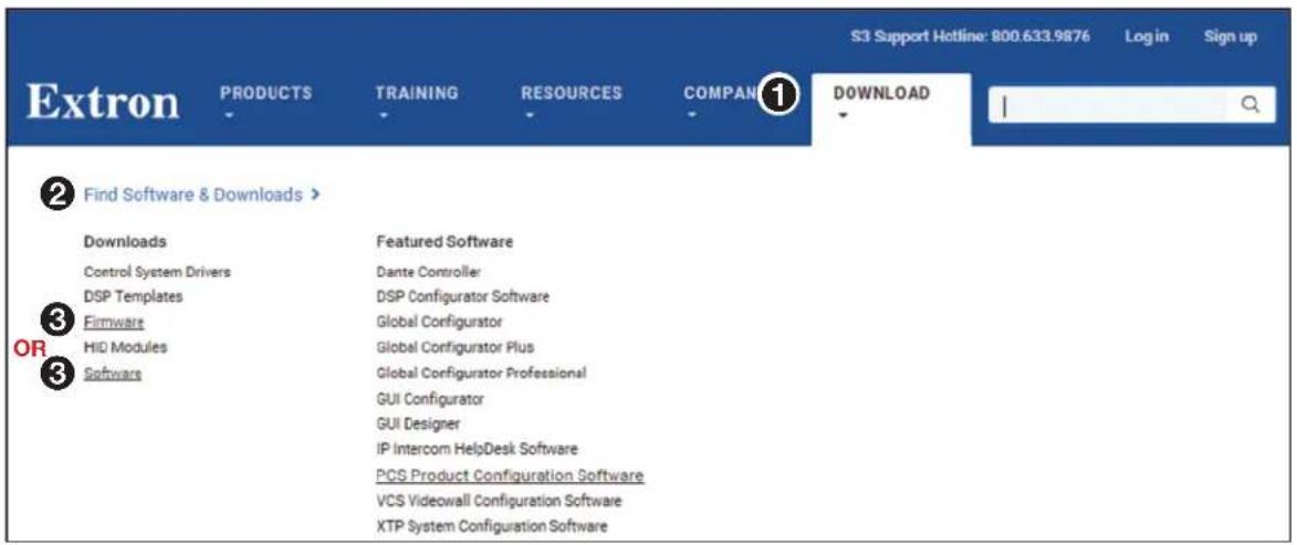
Figure 31. Selecting the Download Tab
- Click the Software or Firmware link, as appropriate to the operation you are performing (③). The main download page opens (see figure 32 on the next page).
Figure 32. Downloading from the Main Download Page
- Click the desired filtering letter (see figure 32, ①) to jump to the nearest page of downloads.
- Click Download for the desired software or firmware package to download (see figure 32, ②). The Log in dialog box appears (see figure 33).
Figure 33. Log in Dialog Box
- Enter the E-Mail address and Password associated with your Extron insider account (see figure 33, ① on the previous page).
TIPS:
- Click Sign up (②) to obtain website credentials.
- Click Keep me logged in (3) to eliminate steps 4 and 5 in future downloads.
-
Enter your registered email address and click Retrieve Password (4) if you have forgotten your credentials.
-
Click Log in to copy the software to the computer (5).
-
If your browser asks you to confirm that you want to continue, click Run or make a similar confirmation that you want to run the installation (see figure 34, ①).
Do you want to run or save MATRIX_SW_v8x3.exe (14.9 MB) from media.extron.com?
This type of file could harm your computer.

Run
Save

Cancel
Figure 34. Download Warning and Confirmation
NOTE: Figure 34 may appear different or may not appear at all, depending on your Web browser choice and its security settings.
- For a firmware download, exit this procedure and return to Updating the Firmware on page 82 or Firmware Upgrade Page on page 107.
- Follow the on-screen instructions. The installation creates a C:\Program Files\Extron\Matrix_Switchers directory, and it places the following four icons into a group folder named "Extron Electronics\Matrix Switchers":
NOTE: The folder is C:\Program Files(x86)\ ... for Windows 7 or Windows 8.
• MATRIX Switcher + Control Program
- Check for Matrix Updates
• MATRIX Switcher + Help
• Uninstall MATRIX Switcher
Using the Matrix Switcher Control Software
Many items found in the Matrix Switchers Control Program are also accessible via front panel controls (see Front Panel Operations on page 25) and under SIS control (see the Programming Guide section, beginning on page 52).
- To run the Matrix Switchers Control Program, click
Start > Programs > Extron Electronics > Matrix Switchers > MATRIX Switcher + Control Pgm.
The Comm Port Selection window (see figure 35) appears.
MTRX

MATRIX Switcher+
Control Pgm
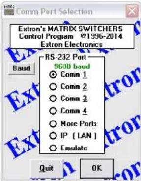
Figure 35. Comm Port Selection Window
- Choose either the Comm port that is connected to the rear panel Remote port or front panel Config (RS-232) port, IP [LAN], or Emulate.
- If you selected a comm port, check the baud rate displayed in the comm port selection dialog box.
NOTE: To change the baud rate, click the Baud button and double-click the desired baud rate. The default is 9600.
| 9600 baud |
| 19200 baud |
| 38400 baud |
| 115200 baud |
Click OK. The Extron Matrix Switchers Control Program window appears, displaying the current configuration of the attached matrix (see figure 37 and figure 38 on page 77). Proceed to step 4.
If you selected IP [LAN], click OK and proceed to step 3.
- If you selected Emulate, click OK and see Using Emulation Mode on page 91.
- If you selected IP [LAN] in step 2, the IP Connection dialog box appears (see figure 36).
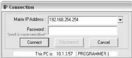
Figure 36. IP Connection Dialog Box
a. Examine the Matrix IP Address field in the IP Connection window. The field displays the last IP address entered.
If the IP address is correct: Proceed to step 3b.
If the address is not correct: Either click in the Matrix IP Address field and enter the IP address or click on the scroll down button (✗) and select from among the recently used addresses. Proceed to step 3b.
NOTE: If the local system administrators have not changed the value, the factory-specified default, 192.168.254.254, is the value for this field.
b. If the switcher is password protected, click in the Password field and enter the appropriate administrator or user password.
NOTE: The factory configured passwords for all accounts on this device have been set to the device serial number. Passwords are case sensitive.
c. Click Connect. The Extron Matrix Switchers Control Program window appears, displaying the current configuration of the attached matrix (see figure 37 and figure 38 on the next page). Proceed to step 4.
- If you logged on using the administrator password or if no password was required, the program connects you to the matrix switcher with all of the administrator rights and privileges. Administrators have full access to all switching capabilities and editing functions.
- If you logged on using the user password, the program connects you to the matrix switcher with only user capabilities.
-
If an incorrect password was entered, the program beeps and returns to the password entry display. Users can create ties, create and recall presets, set mutes, and view all settings with the exception of passwords.
-
Operate the switcher as desired.
-
To create a tie, drag an input box to one or more output boxes. To remove a tie, drag the output box to its tied input box or to the trash can.
- To make the control program easier to use, assign a device icon to each input and output. Click on a box that represents an input or output, and drag the desired icon onto the box from the icon palette that appears.
- For quick display of information on a specific input or output device, position the cursor over that device in the control program window. The program opens a window that details the connection to that device (see the inset box in figure 38).
TIP: Print a map of the current configuration by clicking File > Print Tie Map.
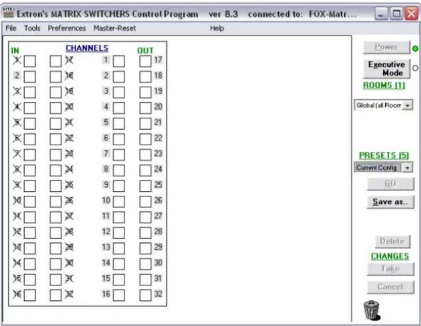
Figure 37. Extron Matrix Switchers Control Program Window (no Icons or Ties)
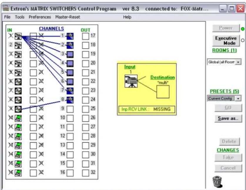
Figure 38. Sample Program Window (Icons Assigned and Ties Created)
IP Settings / Options window
The IP Settings / Options window (click Tools > IP options, see figure 39) provides a location for viewing and, if connected via the either serial port or if you are logged on via the LAN port as an administrator, editing settings unique to the Ethernet interface. See the Ethernet Link section, beginning on page 119 for basic information about IP addresses. None of the fields on this screen can be edited while you are logged on as a user.
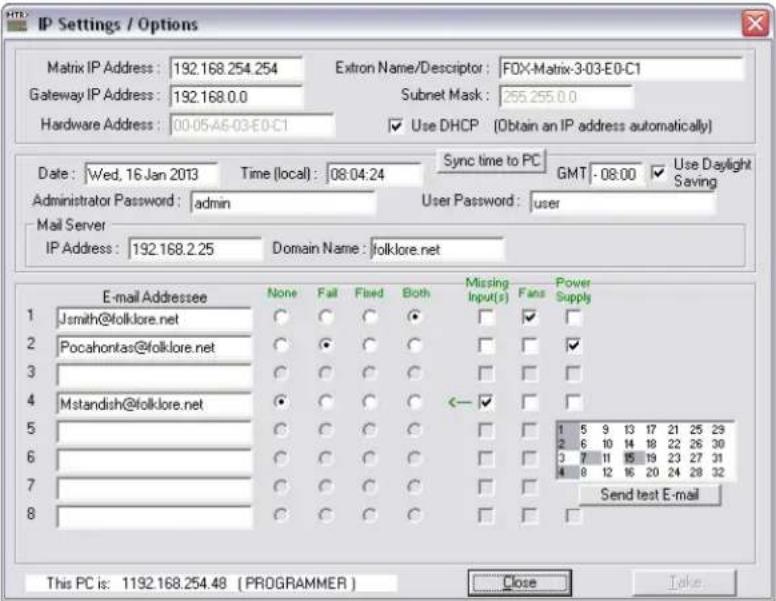
Figure 39. Control Program IP Setting/Options Window
NOTES:
- Editing variables in the IP Settings / Options window while connected via the Ethernet port can immediately disconnect the user from the switcher. Extron recommends editing the settings on this screen using a serial port and protecting the Ethernet access to this screen by assigning an administrator password to qualified and knowledgeable personnel only.
- When the control program is connected to the switcher via the RS-232 link, the Administrator Password and User Password fields are not masked. If a password has been inadvertently changed to an unknown value, you can look up and change a password in this window without knowing the current password.
Address and Name fields
- The Matrix IP Address field contains the IP address of the connected matrix switcher. This value is encoded in the flash memory in the switcher.
- The Gateway IP Address field identifies the address of the gateway to the controlling PC to be used if the matrix switcher and the mail server are not on the same subnet.
- The Subnet Mask field is used to determine whether the matrix switcher is on the same subnet as the controlling PC when you are subnetting. For more information, see the Subnetting — A Primer section on page 124.
- The Mail Server IP Address field displays the IP address of the mail server that handles the email for the facility in which the FOX matrix switcher is installed.
Valid addresses consist of four 1-, 2-, or 3-digit numeric subfields, properly called octets, separated by dots (periods). Each octet can be numbered from 000 through 255. Leading zeroes, up to 3 digits total per field, are optional. Values of 256 and above are invalid.
The default addresses are as follows, but if these conflict with other equipment at your installation, you can change the addresses to any valid value:
• IP address 192.168.254.254
- Subnet mask 255.255.0.0
• Gateway address 0.0.0.0
NOTES:
- The address fields are unavailable when the Use DHCP check box is selected.
- Editing the addresses while connected via the Ethernet port can immediately disconnect the user from the switcher. Extron recommends editing this field using one of the serial ports and protecting the Ethernet access by assigning an administrator password to qualified and knowledgeable personnel only.
The Extron Name/Descriptor field contains the name of the matrix switcher. This descriptor can be changed to any valid name, up to 12 alphanumeric characters.
The Mail Server Domain Name field displays the domain name that the FOX matrix switcher uses to log on to the email server. Standard domain conventions (such as xxx.com) apply.
NOTE: The HTML language reserves certain characters for specific functions (see Special Characters on page 70). In the Mail Server Domain Name field, the @ character is acceptable only as the lead-in to the domain name (such as @folklore.net).
Edit any of these fields as follows:
- Click in the desired field. The graphic cursor becomes a text cursor.
- Edit the address or name as desired.
- Press the
key on the keyboard or click in another field to exit the field. - Click the Take button to make the address change take affect.
Hardware Address field
The hardware address is hardcoded in the FOX matrix switcher and cannot be changed.
Use DHCP check box
The Use DHCP check box directs the FOX matrix switcher to ignore any entered IP addresses and to obtain its IP address from a Dynamic Host Configuration Protocol (DHCP) server (if the network is DHCP capable). Contact the local system administrator to determine whether to use DHCP.
Date, Time (local), and GMT (offset) fields
The Date field displays the current date in the Greenwich Mean Time zone.
The Time (local) field displays the current time in the local time zone.
The GMT field displays the amount of time, in hours and minutes, that the local time varies from the GMT international time reference.
NOTE: Rather than the following procedure, you can click the Sync Time to PC button to set the switcher to the internal time of your computer.
If desired, adjust any of these values as follows:
- Click in the desired field. The field changes to an editable field appropriate to the value being changed and the graphic cursor becomes a text cursor.
- The Date field becomes a set date field, with the date in the format (M)M/(D)D/YYYY. Leading zeroes are not shown.
Date : 1/14/2013
- The Time (local) field becomes a set time field, with the time in the format HH:MM:SS (00:00:00 to 23:59:59).
Time (local): 03:57:00
- The GMT field becomes a set offset field, with the offset in the format ± HH:MM (-12:00 to +14:00).
GMT - 8:00
- Edit the field as desired to set the proper value. For time, remember to use 24-hour time. Leading zeroes are optional.
- Press the
key on the keyboard or click in another field to exit the set date field. - Click the Take button to make the date change take affect.
Sync Time to PC button
Clicking the Sync Time to PC button causes the computer you are operating to send its internal time to the switcher in a set time command.
Use Daylight Saving check box
To turn Daylight Saving Time on and off for North America, select the Use Daylight Saving check box. When Daylight Saving Time is turned on, the switcher automatically updates its internal clock between Standard Time and Daylight Saving Time in the spring and fall on the date that the time change occurs in North America. When Daylight Saving Time is turned off, the switcher does not adjust its time reference.
NOTE: For Daylight Saving Time in Europe and Brazil, see the Set Daylight Saving Time SIS command on page 68.
Administrator Password and User Password fields
The Administrator Password field displays the password required to log on to the matrix switcher via the Ethernet port with all of the rights and privileges of the administrator. The User Password field displays the password required to log on to the matrix switcher via the Ethernet port as a user, without all of the rights and privileges of the administrator. Passwords are case sensitive and are limited to 12 upper-case and lower-case alphanumeric characters.
Both password fields are masked with asterisks (***** ) as a security measure.
NOTES:
- The factory configured passwords for all accounts on this device have been set to the device serial number. Passwords are case sensitive.
- If the device is reset, the password reverts to the original password condition (no password).
- On password-protected connections, there are two levels of protection: administrator and user. Administrators have full access to all switching capabilities and editing functions. Users can create ties, create and recall presets, set mutes, and view all settings with the exception of passwords.
- Editing the Administrator Password field while connected via the Ethernet port can immediately disconnect the user from the switcher. Extron recommends editing this field using either serial port and protecting the Ethernet access to this screen by assigning an administrator password to qualified and knowledgeable personnel only
NOTES:
- An administrator password must exit before a user password can be created.
- The HTML language reserves certain characters for specific functions (see Special Characters on page 70).
Edit either password field as follows:
- Click in the desired Password field. The pointer tool becomes a text cursor.
- Edit the case-sensitive password as desired.
- Press the keyboard
key or click in another field to exit the Password field. - Click the Take button to make the password change take effect.
Mail Server IP Address field
The Mail Server IP Address field displays the IP address of the mail server that handles the email for the facility in which the matrix switcher is installed. Standard IP protocol rules apply to the mail server IP address.
Edit this field as follows:
- Click in the Mail Server IP Address field. The pointer tool becomes a text cursor.
- Edit the IP address as desired.
- Press the keyboard
key or click in another field to exit the Mail Server IP Address field. - Click the Take button to make the address change take effect.
Mail Server Domain Name field
The Mail Server Domain Name field displays the domain name that the matrix switcher uses to log on to the email server. Standard domain conventions (such as xxx.com) apply.
NOTE: The HTML language reserves certain characters for specific functions (see Special Characters). In the Mail Server Domain Name field, the @ character is only acceptable as the lead-in to the domain name (such as @folklore.net).
Edit this field as follows:
- Click in the Mail Server Domain Name field. The pointer becomes a text cursor.
- Edit the name as desired.
- Press the keyboard
key or click in another field to exit the Mail Server Domain Name field. - Click the Take button to make the name change take effect.
E-mail Addressee fields
The five E-mail Addressee fields permit the administrator to identify the email addresses of the personnel to whom the FOX matrix switcher emails notification of its failure and repair status. Figure 40 shows a typical email from the switcher.
Miles Standish
From: FOX-Matrix-3-03-E0-C1@folklore.net
Sent: Wednesday, January 16, 2013 11:22 AM
To: Miles Standish
Subject: FOX-Matrix-3-03-E0-C1 - Fans restored.
Wed, 16 Jan 2013 11:22:48
Unit Name = FOX-Matrix-3-03-E0-C1
Unit IP Address = 192-168-254-254
Figure 40. Typical FOX Matrix Switcher Email
The radio buttons and check boxes associated with each address field permit the administrator to specify specific email requirements for each recipient.
Edit these fields and controls as follows:
- Click in the desired E-mail Addressee field. The graphic cursor becomes a text cursor.
- Edit the email address as desired. Standard email address conventions (for example: nnnnn@xxx.com) apply.
- Press the
key on the keyboard or click in another field to exit the E-mail Addressee field. - In the square check boxes associated with each addressee, select one or more options about which the addressee is to be emailed: Missing Input(s), Fans, and Power Supply. In the floating box that contains the input numbers, select the inputs to be monitored.
- In the round radio buttons associated with each addressee, select whether the addressee is to be emailed of failures, fixes, both, or not to be notified. The None radio button is useful for temporarily removing personnel from the email list when they are unavailable, such as when travelling or on vacation.
- If desired, click the Send test E-mail button to test the email function.
- Click the Take button to make the email address changes take affect.
Updating the Firmware
The firmware upgrade utility provides a way to replace the firmware that is coded on the control board of the switcher without taking the switcher out of service.
NOTE: Upgrading the firmware does not overwrite the current configuration or presets.
Update the switcher firmware as follows:
- Perform steps 1 through 7 of Installing the Software, beginning on page 72, to download the firmware upgrade from the Extron website.
- Click Run in the File Download and Security Warning dialog boxes (see figure 41 on the next page, ①). The PC extracts the firmware update received from the Extron website and starts the Extron Installation Program to extract the firmware file.
- Click Next in the Firmware Upgrade window (2). The program extracts the firmware files and places them in a folder identified in the InstallShield Wizard window.
ATTENTION:
- Note the folder to which the firmware file is saved. When downloaded from the Extron website, the firmware is placed in a subfolder of:
- Windows 7 or Windows 8: C:\Program Files (x86)\Extron\Firmware
- Older versions: C:\Program Files\Extron\Firmware
-
The original factory-installed firmware is permanently available on the matrix switcher. If the attempted firmware upload fails, the switcher reverts to the factory-installed firmware.
-
Click Finish to exit the program (see figure 41, ③).
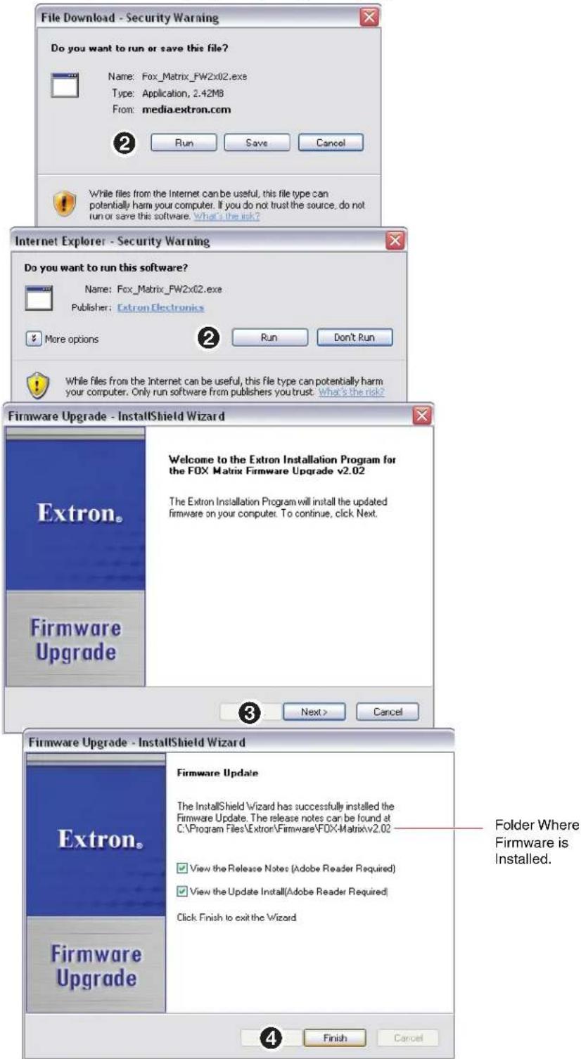
Figure 41. Downloading Firmware Upgrade Files
-
Connect the computer to either serial port (see page 13 and page 17) or the LAN port (see page 13) of the switcher.
-
Start the Matrix Switchers Control Program and connect to the matrix switcher (see Using the Matrix Switcher Control Software in this chapter, steps 1 through 3, starting on page 75).
-
Click Tools > Update firmware...
- If the switcher is connected via the LAN port, the Select Files window appears (see figure 42). Perform "Ethernet-connected firmware upload," below.
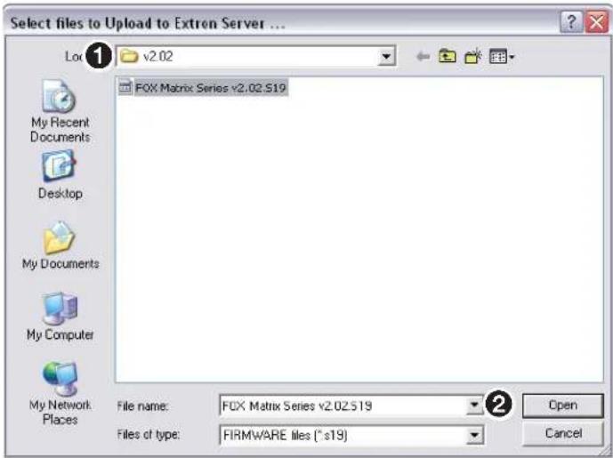
Figure 42. Select File Window
- If the switcher is connected via either serial port, the Extron Firmware Loader window opens (see figure 43 and "Serial-port-connected firmware upload" below).
Ethernet-connected firmware upload
-
Navigate to the folder where you saved the firmware upgrade file (see figure 42, ①). Select the file.
-
Click the Open button (2). The software advises you that you are about to reprogram the switcher firmware. Click OK to continue.
A status window, which shows the progress of the upload, appears. The firmware upload to the FOX matrix switcher may take a few minutes.
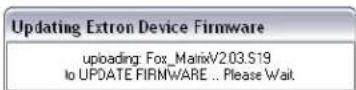
Serial-port-connected firmware upload
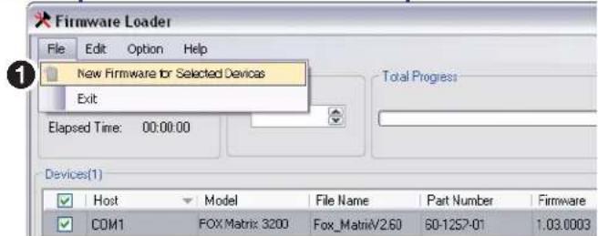
Figure 43. Extron Firmware Loader Window
- Select the switcher and click File > New Firmware for Selected Devices (see figure 43, ①). The Choose Firmware File dialog box appears (see figure 44 on the next page).
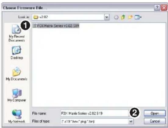
Figure 44. Choose Firmware File Window
- Navigate to and select the new firmware file (see figure 44, ①).
- Click Open (2). The Choose Firmware File window closes.
- In the Firmware Loader window, click Begin (see figure 45, ①).
The Total Progress and Progress status bars show the upload progress. The firmware upload may take several minutes. Once the status bars have progressed from 0% to 100%, and Status is listed as Complete, the firmware loader utility resets the switcher.
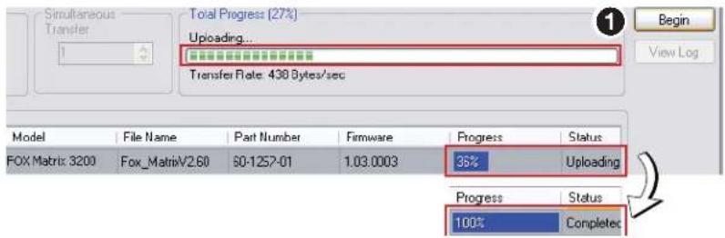
Figure 45. Firmware Loader Screen
- Click Exit to close the Firmware Loader.
NOTE: The firmware loader increases the baud rate to 115,200. The firmware loader may not return the serial port to its earlier baud rate, making communications with the switcher impossible. If you cannot communicate with the switcher after a firmware upload, change the baud rate on your computer and, if necessary, see Selecting the Rear Panel Remote Port Protocol and Baud Rate on page 42.
Uploading HTML Files
You can create customized HTML pages for the switcher to display. The HTML Files List window (see figure 46) provides a way to view the contents of the file system of the switcher and to upload custom HTML pages to the switcher.
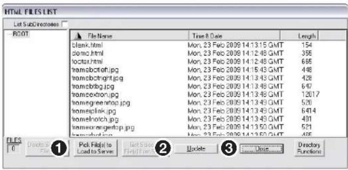
Figure 46. HTML Files List Window
NOTES:
- The files listed in figure 46 are shown for example only and may not be present on your switcher.
- The HTML Files List window is for inserting your custom HTML pages. This is not the window to replace the firmware that controls all switcher operation. See Updating the Firmware on page 82 to replace the firmware.
- The HTML language reserves certain characters for specific functions (see Special Characters on page 70).
Upload HTML pages as follows:
- Connect the PC to the FOX matrix switcher via a serial port or the LAN port.
- Start the Matrix Switchers Control Program and connect to the FOX matrix switcher (see Using the Matrix Switcher Control Software, steps 1 through 3, starting on page 75).
- Click Tools > HTML File Manager.
- Click the Pick File(s) to Load to Server button (see figure 46, ①). An open file window appears.
- Navigate to the folder where you saved the HTML file or files. Select the file or files.
NOTES:
- To select multiple files, hold the
key while you select the desired files. -
If you want one of the custom HTML files that you created to be the default start-up page, name the file "index.html." The FOX matrix switcher looks for that file name when you first connect to it using an Internet browser.
-
Click the Open button. The upload of the file or files to the FOX matrix switcher may take a few minutes.
- Click the Update button to confirm the upload (2).
- Click the Close button to exit the HTML Files List window (③).
Windows Buttons, List Boxes, and Trash Can
The buttons, list boxes, and trash can on the right side of the program window perform the following functions:
• Power — Unavailable for FOX matrix switchers.
- Executive Mode — Allows you to lock out front panel operations, except for the view-only mode functions. Click the button to cycle between locked (the indicator displays red) and unlocked (the indicator is white).
- Rooms — Displays a list of up to 10 rooms. You can select a room from the list to display it in the window.
NOTE: A room is a subset of outputs that the operator logically relate to each other. The FOX matrix switcher supports up to 10 rooms, each of which can consist of 1 to 16 outputs.
- Presets — Displays a list of up to 32 (FOX Matrix 3200) or 64 (FOX Matrix 7200) global presets and up to 100 room presets. You can select a preset from the list to display it in the window and either activate it (Go) or delete it (Delete).
- Go — Activates the selected preset as the current configuration.
- Save as .. — Allows the current set of ties to be saved as a preset. Enter the preset number when prompted to do so.
- Delete — Allows the current preset to be deleted.
- Changes – Take — Saves any changes made to the displayed configuration.
- Changes – Cancel — Abandons any changes made to the displayed configuration.
- Trash can — Drag and drop from an input or output button to the trash can to unmake all ties associated with that input or output.
Windows menus
File menu
- Save MATRIX settings as ... — Saves a complete set of up to 32 (FOX Matrix 3200) or 64 (FOX Matrix 7200) global presets, rooms, room presets, and preset names plus the last active setting (preset 0), to a file. Saved settings include assigned icons and icon captions.
- Restore MATRIX settings from ... — Loads and activates a previously saved setting file.
- Save This-Session's settings — Saves the current assigned icons and icon captions.
- Restore Last-Session's settings — Loads the icons and icon captions that were saved during the last session. If you saved the changes from the previous session to disk the last time you exited the program, the ties from that session are also loaded.
- Select Printer ... — Selects the target printer.
• Print Tie Map — Prints the tie set that is displayed on the screen. - Exit — Closes the Matrix Switchers Control Program.
| File | Tools | Preferences | Master-Reset |
| Save MATRIX settings as... | |||
| Restore MATRIX settings from ... | |||
| Save This-Session's settings | |||
| Restore Last-Session's settings | |||
| Select Printer ... | ▶ | ||
| Print Tie Map | |||
| Exit | |||
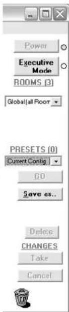
Tools menu
- Assign Device Icons — Displays the complete set of input and output device icons. You can drag any of these icons to the input and output boxes.
- Edit Device Palette — Allows you to add your own device icon graphics.
- Mute-Output settings — Displays the Mute Adjust window, from which you can mute each output.
- FOX Re-clocker settings — Displays the FOX Reclocking Rate Settings window, from which you can select the reclocking rate for one or all outputs and mute and unmute the output.
• View Input Frequencies — Displays the Input Detection window, which shows the data rates for SDI and HD-SDI inputs only. This selection is not available if no BNC 3G/HD/SD-SDI boards are installed. - Update Firmware ... — Allows you to replace the firmware that is coded on the control board of the switcher without taking the switcher out of service (see Updating the firmware on page 82).
- IP Options — Allows you to set IP options (see IP Settings / Options window on page 78).
- HTML File Manager — Displays a list of HTML files installed on the switcher and allows you to upload custom files from a PC connected to the switcher (see Uploading HTML files on page 86).
- Hardware Status — Provides an overall view of the status of the matrix switcher, including the power supply voltages, the temperature status, the Remote RS-232/RS-422 port configuration, and the installed and updated firmware status (see figure 47).
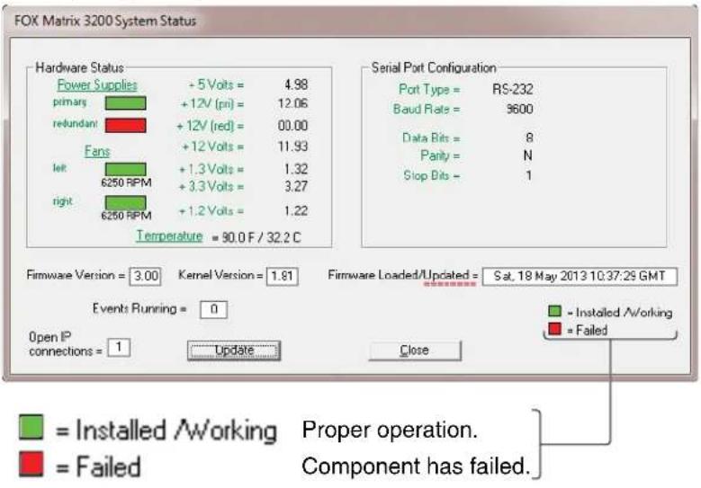
Figure 47. Status Window
| Tools | Preferences | Master-Reset |
| Assign Device IconsEdit Device Palette | ||
| RGB Delay settingsAudio-Input Gain settingsAudio-Output Volume settingsMute-Output settingsFOX Re-clocker settingsView Input Frequencies | ||
| Update Firmware ... | ||
| IP OptionsHTML File ManagerHardware StatusPhysical Switcher Layout | ||
| Name PresetsShow RS-232 StringsI/O Group settingsRoom configurationInitialize ... | ||
• Physical Switcher Layout — Calls the FOX Matrix Physical
Configuration window (see figure 48), which displays the I/O board type installed in each slot. The Channels panel can be helpful in identifying a specific input or output. In figure 48, for example, input 29 is identified as slot 4, input transceiver E (4o05).
![The FOX 4G Matrix 3200 Physical Configuration Slot 1 Multi-Mode A B C D E F G H xmt rcv xmt rcv xmt rcv xmt rcv xmt rcv xmt rcv xmt rcv xmt rcv xmt rcv xmt rcv xmt rcv xmt rcv xmt rcv xmt rcv xmt rcv xmt rcv xmt rcv xmt rcv xmt rcv xmt rcv xmt rcw xmt rcw xmt rcw xmt rcw xmt rcw xmt rcw xmt rcw xmt rcw xmt rcw xmt rcw xmt rcw xmt rcw xmt rcw xmt rcw xmt rcw xmt rcw xmt rcw xmt rcw xmt rcw xmt rcw xmt rcr xmt rcr xmt rcr xmt rcr xmt rcr xmt rcr xmt rcr xmt rcr xmt rcr xmt rcr xmt rcr xmt rcr xmt rcr xmt rcr xmt rcr xmt rcr xmt rcr xmt rcr xmt rcr xmt rcr xmt rcc xmt rcc xmt rcc xmt rcc xmt rcc xmt rcc xmt rcc xmt rcc xmt rcc xmt rcc xmt rcc xmt rcc xmt rcc xmt rcc xmt rcc xmt rcc xmt rcc xmt rcc xmt rcc xmt rcc xmt rccc xmt rccc xmt rccc xmt rccc xmt rccc xmt rccc xmt rccc xmt rccc xmt rccc xmt rccc xmt rccc xmt rccc xmt rccc xmt rccc xmt rccc xmt rccc xmt rccc xmt rccc xmt rccc xmt rccc xmt rcccc xmt rccc xmt rccc xmt rccc xmt rccc xmt rccc xmt rccc xmt rccc xmt rccc xmt rccc xmt rccc xmt rccc xmt rccc xmt rccc xmt rccc xmt rccc xmt rccc xmt rccc xmt rccc xmt rccc xmt rcacc xmt rccc xmt rccc xmt rccc xmt rccc xmt rccc xmt rccc xmt rccc xmt rccc xmt rccc xmt rccc xmt rccc xmt rccc xmt rccc xmt rccc xmt rccc xmt rccc xmt rccc xmt rccc xmt rctg160000000000000000000000000000000000000000000000000000000000000000000000000000000000000000000000000000- List-view Inputs Outputs Names OUTPUT 29 Name: Name: SDI/HD-SDI Slot 2 in1 in2 in3 in4 in5 in6 in7 in8 out1 out2 out3 out4 out5 out6 out7 out8 Slot 3 Single-Mode (missing some) Slot 3 x mxt rctg16000000000000000000000000000000000000000000000000000000- Slot 4 x mxt rctg16016161616161616161616161616161616161616161616161616161616161616161616161616161616161616161616161616161- Unknown Type x mxt rctg16161616161616161616161616161616161616161616161616161616161616161- Unknown Type x mxt rctg16222222222222222222222222222222222222222222222222222222222222- Unknown Type x mxt rctg1633333333333333333333333333333333333333333333333333333333333333333333333333333333333333333333333333334444444444444444444444444444444444444444444444444444444444444444444444444444444444444444444444444445- - - - - - - - - - - - - - - - - - - - - - - - - - - - - - - - - - - - - - - - - - - - - - - - - - - - - - - - - - - - - - - - - - - - - - - - - - - - - - - - - - - - - - - - - - - - - 8 = --- 1.5e-5 9 = --- 2.5e-5 1.5 = --- 2.5e-5 9 = --- 2.5e-5 9 = --- 2.5e-5 9 = --- 2.5e-5 9 = --- 2.5e-5 9 = --- 2.5e-5 9 = --- 2.5e-5 9 = --- 2.5e-5 9 = — — — — — — — — — — — — — — — — — — — — — — — — — — — — — — — — — — — — — — — — — — — — — — — — — — — — — — — — — — — — — — — — — — — — — — — — — — — — — — — — — — — — — — — — — — — — — — — — — — — — | XMT RCW x mxt rctg16222222222222222222222222222222222222222222222222222222222222< img src="box">> Legend: Input Output< img src="box"> [box] Input Output< img src="box"> [box] Output< img src="box"> [box] Output< img src="box"> [box] Output< img src="box"> [box] Output< img src="box"> [box] Output< img src="box"> [box] Output< img src="box"> [box] Output< img src="box"> [box] Output< img src="box"> [box] Output< img src="box"> [box] Input: Output: Output: Output: Output: Output: Output: Output: Output: Output: Output: Output: Output: Output: Output: Output: Output: Output: Output: Output: Output: Output: Output: Output: Output: Output: Output: Output: Output: Output: Output: Output: Output: Output: Output: Output: Output: Output: Output: Output: Output: Output: Output: Output: Output: Output: Output: Output: Output: Output: Output: Out](/content/2026/05/942439/images/9df38223ab3716d86cd87f20fc1929182cd793c5744c78cc556c0358f210d9d2.jpg)
Figure 48. Physical Configuration Window
- Name Presets — Allows you to name each of the 32 (FOX Matrix 3200) or 64 (FOX Matrix 7200) memory presets.
NOTE: Preset names are limited to 12 upper- and lower-case alphanumeric characters, space, and the _ and / characters. The HTML language reserves certain characters for specific functions (see Special Characters on page 70).
- Show RS-232 Strings — Displays the ASCII commands that are used by the current configuration. You can refer to these for SIS programming.
- I/O Group settings — Displays the inputs/outputs groups window, which allows you to assign inputs and outputs to any one of four groups (or no group).
- Room configuration — Allows you to assign outputs to rooms or delete outputs from rooms.
NOTE: A room is a subset of outputs that are logically related to each other, as determined by the operator. The FOX matrix switcher supports up to 10 rooms, each of which can consist of 1 to 16 outputs.
- Initialize ... — Initializes and clears any or all of the following: ties, presets, preset names, icon names, and icons.
Preferences menu
- Immediate Changes — Causes changes to take effect immediately.
- Hold/Verify Changes — Delays implementation of changes until the Changes – Take button is clicked.
• Ties as Lines — Displays ties as lines (see figure 49).
Figure 49. Ties Shown as Lines
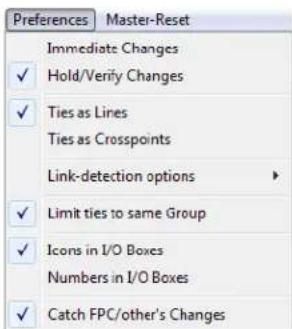
- Ties as Crosspoints — Displays ties as a matrix of inputs and outputs (see figure 50). Ties that have been made are indicated as amber boxes. Ties that will take effect when you click the Take button are indicated by +. Ties that will be broken when you click the Take button are indicated by−.
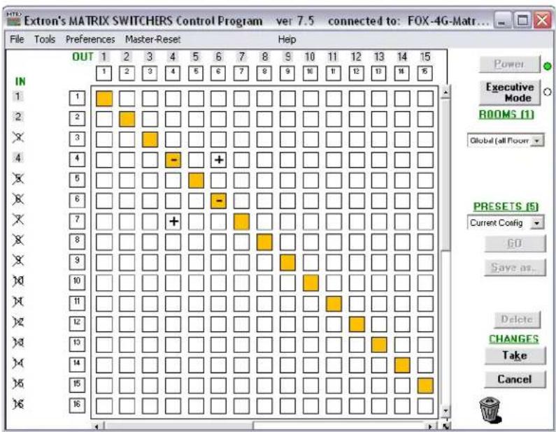
Figure 50. Ties Shown as Crosspoints
- Link-detection options — Allows you to set the link detection feature as follows:
• To automatically refresh the display every 10 seconds.
• To update the display whenever you refresh the screen.
• To never sample and display the link status
NOTE: For the FOX Matrix 7200, this menu selection displays as Freq/Link-detection options.
- Limit ties to same Group — Allows you to limit tie creation using the program to inputs and outputs that are in the same group (similar to front panel operation).
- Icons in I/O Boxes — Erases any numbers in the I/O boxes in either the ties-as-lines window display (see figure 38 on page 77) or the ties-as-crosspoints display (see figure 50, above). You can place icons in the boxes.
- Numbers in I/O Boxes — Erases any icons in the I/O boxes in either the ties-as-lines window or the ties-as-crosspoints display, and fills each box with the associated input or output number.
1
1 1
- Catch FPC/other's Changes — When checked, sets the switcher to report all configuration and setting changes to the serial port or Ethernet connection that turned this selection on. These reports allow the Matrix Switchers Control Program to track the changes that occur in the configuration and settings of the switcher, whether commanded via the front panel, a serial port, or the Ethernet port.
Master-Reset selection
Master-Reset
Master reset performs all of the following functions:
- Clears all ties
- Clears all presets
- Clears all rooms
- Clears all output mutes
- Resets all I/O grouping
NOTE: Master reset does not reset the Internet protocol (IP) settings.
Using Emulation Mode
Emulation mode allows you to set up the software without connecting the switcher. Use emulation mode as follows:
- To run the Matrix Switchers Control Program, click
Start > Programs > Extron Electronics > Matrix Switchers > MATRIX Switcher + Control Pgm.
The Comm Port Selection window (see figure 51) appears.

MATRIX Switcher+
Control Pgm
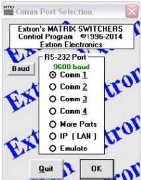
Figure 51. Comm Port Selection Window
- Choose Emulate, and click OK.
- Choose an emulation file to open, and click OK. The file DEMO.MTX provides a sample of a completed matrix setup. Selecting the file NEW.INI or clicking Cancel provides a blank setup window to get you started.
-
Enter the file name under which you want to save any changes to the file, and click OK.
-
Select Fiber Matrix as the Matrix Model, 3200 or 7200 as the Default Size, and either singlemode or multimode for each board installed (see figure 52). Click OK.
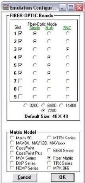
Figure 52. Emulate Mode Configuration
- Continue using the program as described in the Using the Matrix Switcher Control Software, steps 1 through 3, starting on page 75).
Using the Help System
For information about program features, you can access the help program in any of the following ways:
- From the Extron Electronics program folder or group, double-click the MTRX.HLP icon (shown at right).

- From within the Matrix Switcher Control Program, click Help > Contents on the menu bar.
- From within the Matrix Switcher Control Program, press the
Button Label Generator Program
The Button Label Generator software creates labels that you can place in the translucent covers of the input and output selection buttons. You can create labels with names, alphanumeric characters, or even color bitmaps for easy and intuitive input and output selection (see the Removing and Installing Button Labels on page 117 for the procedure for removing and replacing the translucent covers).
Installing the Button Label Generator Software
The Extron Button Label Generator is available on the Extron website. Install it as follows:
- Go to www.extron.com and click the Download tab (see figure 54, ①).
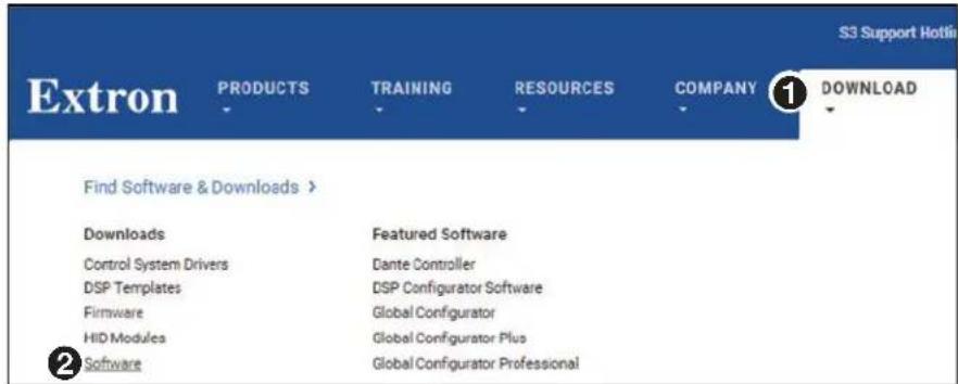
Figure 53. Location of Software on the Website
- Click the Software link on the main download page (②).
- Download and install Button Label Generator on your PC.
By default, the Windows installation creates a C:\Program Files\Extron\ButtonLabelGenerator directory and places the Button Label Generator icon into a group or folder named "Extron Electronics."
NOTE: C:\Program Files(x86)\ ... for Windows 7 or Windows 8.
Using the Button Label Generator Software
- To run the Button Label Generator program, click Start > Programs > Extron Electronics > Button Label Generator > Button Label Generator. The Button Label Generator window appears (see figure 54).
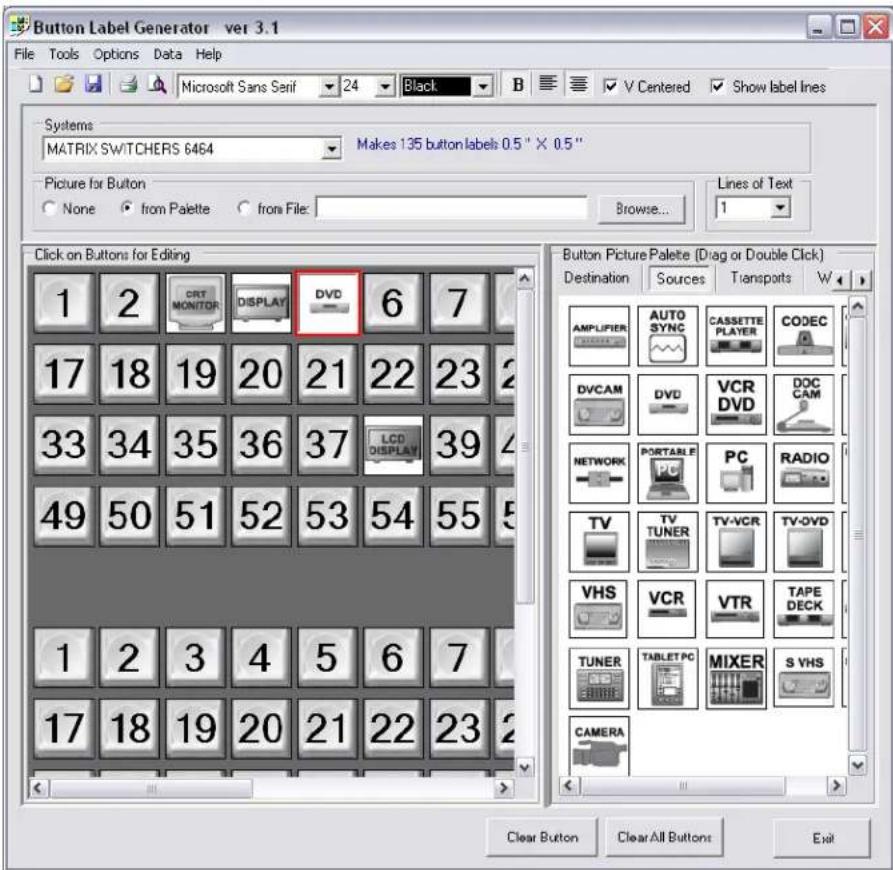
Figure 54. Extron Button Label Generator Window
- In the Systems list, choose the Matrix Switchers 6464 option to match, as closely as possible, the button label size and quantities for your FOX matrix switcher (but without buttons for 65 through 72).
- Using normal Windows controls, you can create and print labels that can be placed in the label windows on the front panel of the switcher.
NOTE: For best results, print on transparent or translucent material.
- Click the Clear All Buttons button and create new labels as many times as necessary to make all of the button labels that you need.
To access the help program, click the Help menu.
HTML Operation
This section introduces using the built-in HTML pages to operate the FOX matrix switchers, including:
- Opening the Embedded Web Pages
- Status Tab
- Configuration Tab
- File Management Tab
- Control Tab
The switcher can be controlled and operated through its LAN port, connected via a LAN or WAN, using a web browser such as the Microsoft Internet Explorer. The display in the browser of the status or operation of the switcher has the appearance of web pages. This chapter describes the factory-installed HTML pages, which are always available and cannot be erased or overwritten.
NOTE: If your Ethernet connection to the matrix switcher is unstable, try turning off the proxy server in your web browser. In Microsoft Internet Explorer, clickTools > Internet Options > Connections > LAN Settings, uncheck the Use a proxy server... box, and then click OK.
Opening the Embedded Web Pages
Access the switcher using HTML pages as follows:
- Start the web browser.
- Click in the Address field of the browser.
- Enter the IP address in the Address field of the browser.
NOTE: If the local system administrators have not changed the value, the factory-specified default, 192.168.254.254, is the value for this field.
- If you want the browser to display a page other than the default page (such as a custom page that you have uploaded), enter a slash (/) and the file name to open after the IP address.
NOTES:
- The Address field of the browser should display the address in the following format:
/ -
The HTML language reserves certain characters for specific functions (see Special Characters on page 70).
-
Press the keyboard
key. The switcher checks to see if it is password protected.
If the switcher is not password protected, it checks and downloads the HTML pages (proceed to step 7).
If the switcher is password protected, the switcher downloads the Windows Security dialog box (see figure 55).
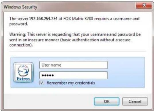
Figure 55. Windows Security Dialog Box
NOTE: A User name entry is not required.
- Click in the Password field and type in the appropriate administrator or user password. Click the OK button.
NOTE: The factory configured passwords for all accounts on this device have been set to the device serial number. Passwords are case sensitive
- The switcher checks several possibilities, in the following order, and then responds accordingly:
- Does the address include a specific file name, such as 192.168.254.254/
- Is there a file in the switcher memory that is named "index.html"? If so, the switcher downloads "index.html" as the default startup page.
- If neither of the above conditions is true, the switcher downloads the factory-installed default startup page, "nortxe_index.html" (see figure 56, below), also known as the System Status page.
Status Tab
System Status Page
The System Status page (see figure 56) provides an overall view of the status of the matrix switcher, including power supply status, individual voltages, and fan status. The System Status page is the default page that the switcher downloads when you connect to the switcher. Access the System Status page from other pages by clicking the Status tab.
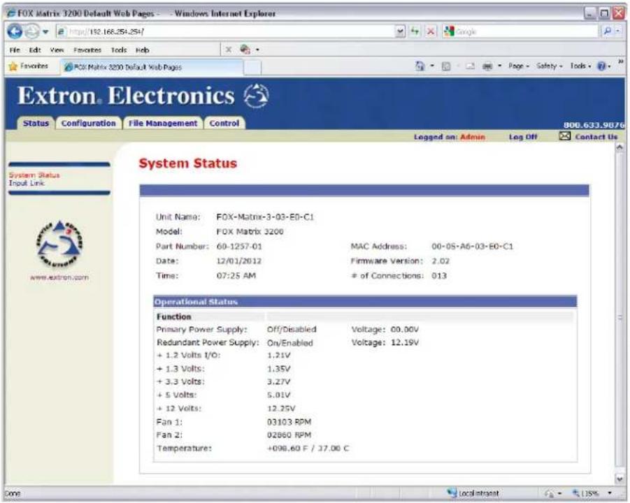
Figure 56. System Status Page
The status web page periodically refreshes to reflect the latest status of the switcher components.
Input Link page
You can view the status of each I/O board slot on the Input Link page (see figure 57). Click the Input Link link to the left of the Status page to download the Input Link page. The Input Link page updates itself every 30 seconds to show the latest status of installed boards, LC (fiber optic) connector installation, and input signal presence.
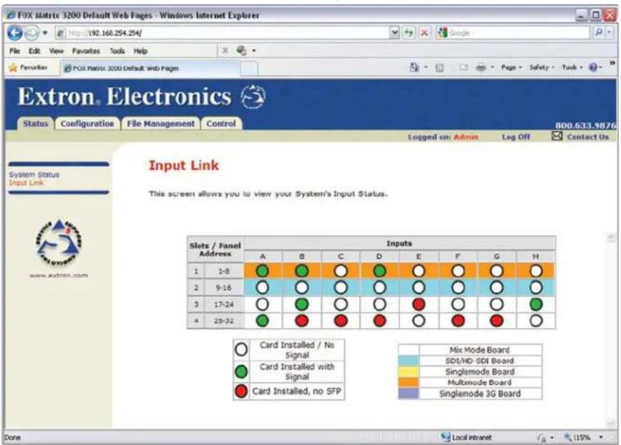
Figure 57. Input Link Page
Configuration Tab
System Settings Page
The FOX matrix switcher downloads the System Settings page (see figure 58) when you click the Configuration tab. The screen consists of fields in which you can view and edit IP administration and system settings. You can access the Passwords, Email Settings, SNMP Settings, and Firmware Upgrade pages by clicking the appropriate link. See Ethernet Link on page 119 for basic information about IP addresses and subnetting.
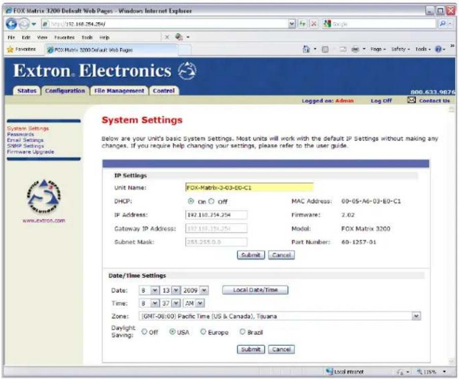
Figure 58. System Settings Page
On password-protected connections, there are two levels of protection: administrator and user. Administrators have full access to all switching capabilities and editing functions. Users can create ties, create and recall presets, set mutes, and view all settings with the exception of passwords.
IP Settings fields
The IP Settings fields provide a location for viewing and editing settings unique to the Ethernet interface. After editing any of the settings on this page, click the Submit button at the bottom of the page.
Unit Name field
The Unit Name field contains the name used as the "from" information when the switcher emails notification of its failed or repaired status. This name field can be changed to any valid name, up to 24 alphanumeric characters.
NOTE: The HTML language reserves certain characters for specific functions (see Special Characters on page 70).
DHCP radio buttons
The DHCP On radio button directs the switcher to ignore any entered IP addresses and to obtain its IP address from a Dynamic Host Configuration Protocol (DHCP) server (if the network is DHCP capable). The DHCP Off radio button turns DHCP off. Contact the local system administrator to determine if DHCP is appropriate.
IP Address field
The IP Address field contains the IP address of the connected switcher. This value is encoded in the flash memory of the switcher.
Valid IP addresses consist of four 1-, 2-, or 3-digit numeric octets separated by dots (periods). Each field can be numbered from 000 through 255. Leading zeroes, up to 3 digits total per field, are optional. Values of 256 and above are invalid.
The factory-installed default address is 192.168.254.254, but if this conflicts with other equipment at your installation, you should ask your network administrator for a new, valid address.
NOTE: IP address changes can cause conflicts with other equipment. Only local system administrators should change IP addresses.
Gateway IP Address field
The Gateway IP Address field identifies the address of the gateway to the mail server to be used if the switcher and the mail server are not on the same subnet.
The gateway IP address has the same validity rules as the system IP address.
Subnet Mask field
The Subnet Mask field is used to determine whether the switcher is on the same subnet as the mail server when you are subnetting. For more information, see Subnetting — A Primer on page 124.
MAC Address field
The Media Access Control (MAC) address is hardcoded in the switcher and cannot be changed.
Firmware field
The Firmware field identifies the installed firmware version. This field is hardcoded in the switcher and cannot be changed.
Model field
The Model field identifies the number of inputs and outputs. This field is hardcoded in the switcher and cannot be changed.
Part Number field
The Part Number field identifies the part number of your switcher. This field is hardcoded in the switcher and cannot be changed.
Date/Time Settings panel
The Date/Time Settings (see figure 59) provides a location for viewing and setting the time functions.
Date/Time Settings
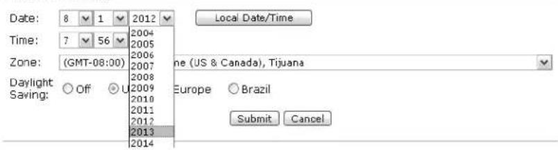
Figure 59. Date/Time Settings Panel
To sync the switcher clock to the connected PC, click the Local Date/Time button and then click the Submit button.
NOTE: Using the Local Date/Time button has no effect on the Zone and Daylight Savings functions.
For more complete control of the date and time settings, change the settings as follows:
-
Click the list for the variable to be changed. The adjustable variables are month, day, year, hours, minutes, AM/PM, and (time) zone. A drop-down scroll box appears (the year list is selected in figure 59).
-
Click and drag the slider or click the scroll up ▶ button or the scroll down ▼ button until the desired value is visible.
-
Click the desired value.
NOTES
- If setting the time, set the local time. The Zone variable allows you to then enter the offset from Greenwich Mean Time (GMT).
-
The Zone field identifies the standard time zone selected and displays the amount of time, in hours and minutes, that the local time varies from the GMT international time reference.
-
Repeat steps 1 through 3 for other variables that need to be changed.
-
If appropriate, select the appropriate Daylight Saving radio button to turn on the daylight savings time feature for your region or nation.
NOTE: When Daylight Saving Time is turned on, the switcher automatically updates its internal clock between Standard Time and Daylight Saving Time in the spring and fall on the date that the time change occurs in the country or region selected. When Daylight Saving Time is turned off, the switcher does not adjust its time reference.
- Click the Submit button.
Passwords Page
Access the Passwords page (see figure 60) by clicking the Passwords link on the System Settings page.
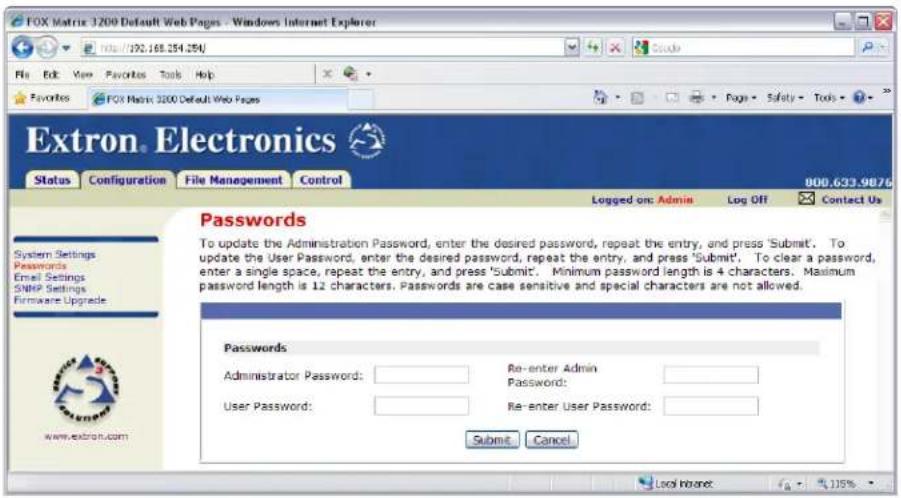
Figure 60. Passwords Page
NOTES:
- The factory configured passwords for all accounts on this device have been set to the device serial number. Passwords are case sensitive.
- If the device is reset, the password reverts to the original password configuration (no password).
- On password-protected connections, there are two levels of protection: administrator and user. Administrators have full access to all switching capabilities and editing functions. Users can create ties, create and recall presets, set mutes, and view all settings with the exception of passwords.
- If the switcher is password protected, fields on this page can be edited only by personnel logged in as administrators.
- An administrator password must exist before a user password can be created.
- The HTML language reserves certain characters for specific functions (see Special Characters on page 70).
The fields on the Passwords page are for entering and verifying administrator and user passwords. Passwords are case sensitive and are limited to as many as 12 upper-case and lower-case alphanumeric characters. Each password must be entered twice; once in the Password field and then again in the Re-enter Password field. Characters in these fields are masked by asterisks (*****). If you do not want to password protect an access level, leave the Password field and the Re-Enter Password field blank. After entering the password in both fields, click the Submit button.
Resetting a password
Reset an existing password so that no password is required as follows:
- Clear any existing password in both the Password and Re-enter Password fields.
- Tap the
bar once to enter a single ASCII space character in both the Password and Re-enter Password fields. - Click the Submit button.
Email Settings Page
Reach the Email Settings page (see figure 61) by clicking the Email Settings link on the System Settings page. The Email Settings page has fields for setting up the email notification capabilities of the switcher. For the email settings and for each row of the email notification settings, click the Edit button to make the fields available for editing. The button changes to Save. After editing the settings associated with the Edit/Save button, click the Save button.
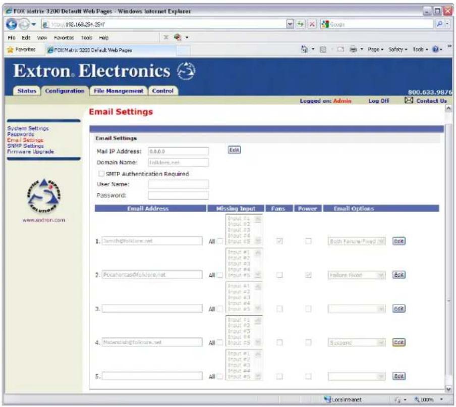
Figure 61. Email Settings Page
Mail IP Address field
The Mail IP Address field displays the IP address and the domain name of the mail server that handles the email for the facility in which the switcher is installed. Standard IP protocol rules apply.
Domain Name field
The Domain Name field displays the domain name that the FOX matrix switcher uses to log on to the email server. Standard domain name conventions (for example: xxx.com) apply.
NOTE: The HTML language reserves certain characters for specific functions (see Special Characters on page 70). The @ character is acceptable only as the lead-in to the domain name (such as @folklore.net).
Setting up SMTP authorization
If desired, set the FOX matrix switcher to require SMTP authorization before accepting any email as follows:
-
Click Edit. The button changes to Save.
-
Check the SMTP Authorization Required check box, located below the Domain Name field. This enables the User Name and Password fields below the check box.
-
Enter a user name and a password in the User Name and Password fields. For the FOX matrix switcher to accept their email messages, senders must enter the user name and password.
NOTES:
- The factory configured passwords for all accounts on this device have been set to the device serial number. Passwords are case sensitive.
- If the device is reset, the password reverts to the original password configuration (no password).
- For the user name, any combination of letters, numerals, spaces, and symbols except the comma (,) and the single and double quotation marks (' and ") are valid. For the password, all characters except the comma are valid. The user name and password can each be from 1 to 30 characters.
-
Both a user name and a password must be specified.
-
Click Save to save the user name and password.
Deselecting SMTP authorization
Remove SMTP authorization as follows:
- Click Edit. The button changes to Save.
- Click (deselect) the SMTP Authorization Required check box.
- Click Save.
Email Address fields
The five Email Address fields identify the email addresses of the personnel to whom the FOX matrix switcher emails notification of its failure and repair status. Standard email address conventions (nnnnn@xxx.com) apply.
The check boxes and list boxes associated with each address field permit you to specify specific criteria under which the switcher will email recipients.
- In the associated Missing Input list boxes, select the inputs to monitor for presence or absence of a signal.
- Check the Fans and Power boxes to monitor the cooling and power supplies.
- In the associated Email Options list, select whether the recipient is to be emailed of failures, fixes, both, not notified, or to be removed from the email list. The Suspend option is useful for temporarily removing personnel from the email list when they are unavailable, such as when travelling or on vacation.
- Deleting an email addressee and clicking the Submit button removes the recipient from email notification completely.
SNMP Settings Page
NOTES:
- Simple Network Management Protocol (SNMP) is an internet-standard protocol for IT personnel to manage devices on an IP network. It is not the intent of this guide to define SNMP further than this and this section is intended for users who are familiar with SNMP protocol.
- The matrix switcher can report alarm events via an SNMP trap, providing simple integration with network management systems (NMS).
- When communicating using SNMP and generating SNMP traps (alarms and notifications), the matrix switcher complies with the requirements of SNMP v2c.
- IT personnel — Contact the S3 Sales & Technical Support Hotline to obtain all Extron-specific Management Information Base (MIBs). See the contact numbers listed on the Extron webpage for the office nearest you.
Reach the SNMP Settings page (see figure 62) by clicking the SNMP Settings link on the System Settings page. The SNMP Settings page has fields for establishing the general SNMP settings and fields to establish SNMP monitoring and optional traps.
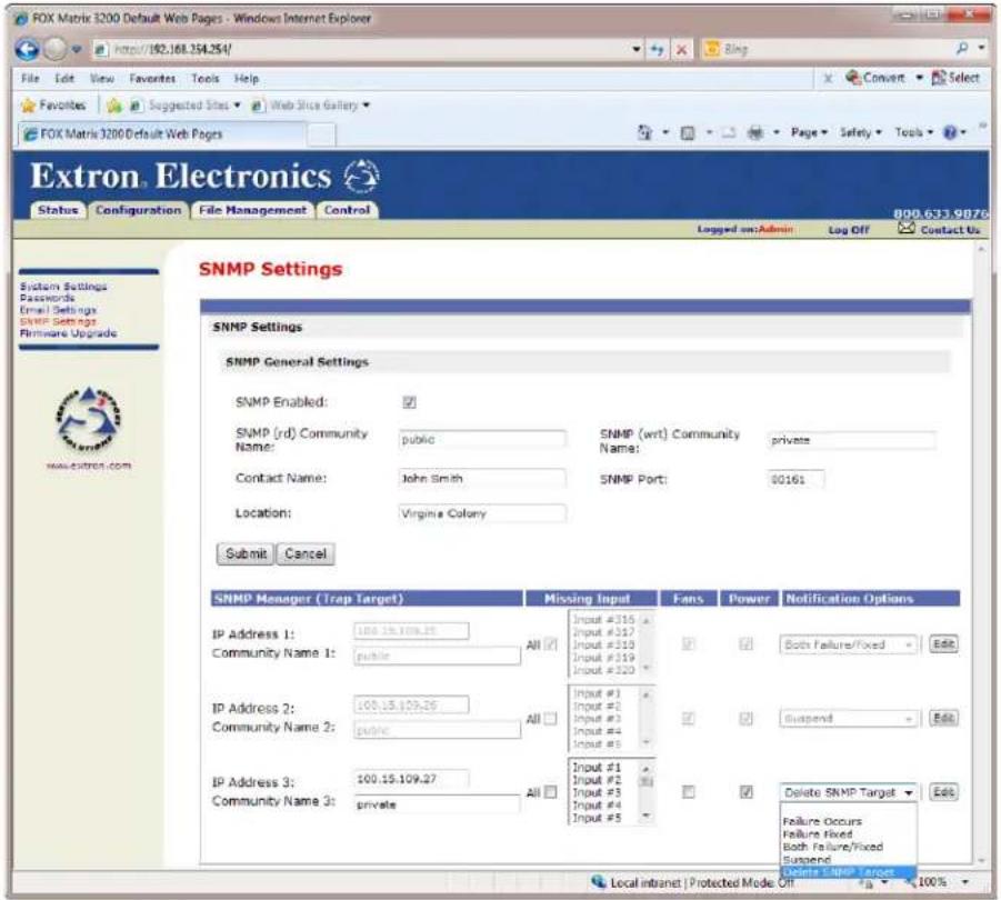
Figure 62. SNMP Settings Page
SNMP General Settings fields
To edit the SNMP General Settings fields, ensure that the SNMP Enabled check box is selected (SNMP is disabled by default). Click the Submit button to save all changes or the Cancel button to abandon changes.
SNMP Community Name fields — The two names are similar to passwords, granting public, read-only [SNMP (rd)] and private, read-write access [SNMP (wrt)] to the NMS. The default names are public and private.
Contact Name and Location fields — The two fields add optional information as to the location of the NMS. By default, Not Specified is assigned to the Name and Location fields.
SNMP Port field — This field identifies the port that the NMS uses to communicate with the switcher and should only be changed by IT personnel. The default port is 161.
SNMP Manager (Trap Target) fields
To edit each row of the SNMP Manager (Trap Target) settings, click the Edit button to make the fields available for editing. The button changes to Save. After editing the associated settings, click the Save button.
The three IP Address fields identify up to three NMS targets to receive trap notifications of the switcher failure and repair status or a mix of trap types to the same target.
The check boxes and list boxes associated with each IP address field permit the operator to specify specific criteria under which the switcher sends trap notifications.
- In the associated Missing Input list boxes, select the inputs to trap the presence or absence of a signal.
- Check the Fans and Power boxes to trap the fans and power supplies.
- In the associated Notification Options list, select whether to notify the target of failures, fixes, both, not notified, or to remove the target from trap list (select Delete SNMP Target). The Suspend option is useful for temporarily removing NMS stations from the notification list when they are unavailable.
Firmware Upgrade Page
The Firmware Upgrade (see figure 63) page provides another way to replace the firmware that is coded on the control board of the switcher without taking the switcher out of service. Access the page by clicking the Firmware Upgrade link on the System Settings page.
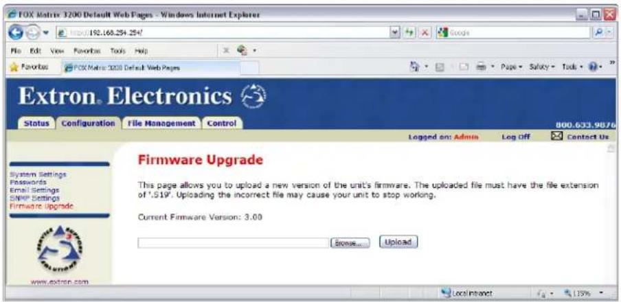
Figure 63. Firmware Upgrade Page
Update the switcher firmware as follows:
NOTE: The Firmware Upgrade page is only for replacing the firmware that controls all switcher operation. To insert your own custom HTML pages, see File Management Page, on the next page.
- Perform steps 1 through 5 of Installing the Software, on page 72, to download the firmware upgrade from the Extron website.
- Connect the PC to the FOX matrix switcher via the LAN port of the switcher.
- Access the FOX matrix switcher using HTML pages.
- Click the Configuration tab (see figure 64, ①).
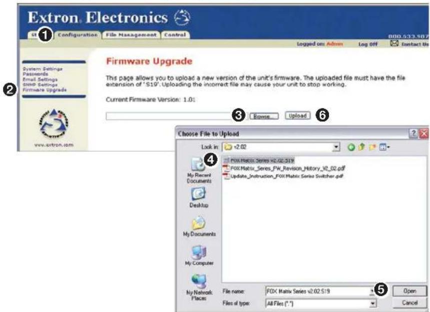
Figure 64. Firmware Upgrade
- Click the Firmware Upgrade link (see figure 64 on the previous page, ②).
- Click the Browse button (③). A Choose File to Upload dialog box appears.
- Navigate to the folder where you saved the firmware upgrade file and select it (④).
ATTENTION:
- When downloaded from the Extron website, the firmware is placed in a subfolder of:
- Windows 7 or later: C:\Program Files (x86)\Extron\Firmware
- Older versions: C:\Program Files\Extron\Firmware
-
The original firmware is permanently available on the switcher. If the attempted firmware upload fails, the switcher reverts to the factory-installed firmware.
-
Click the Open button (5).
- Click the Upload button (6). The firmware upload may take a few minutes.
File Management Tab
File Management Page
To delete files such as user-supplied HTML pages from the switcher or to upload your own files to the switcher, click the File Management tab. The switcher downloads the File Management HTML page (see figure 65).
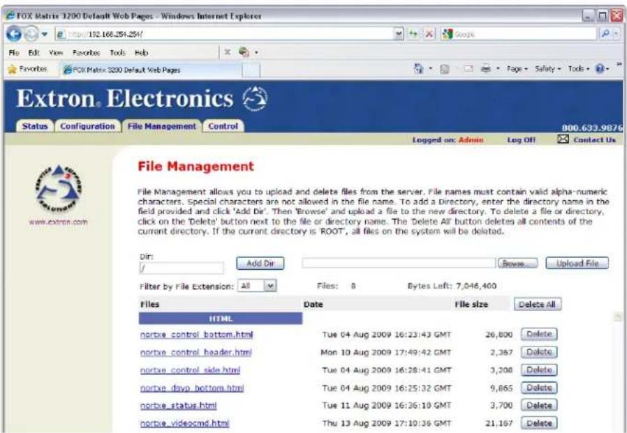
Figure 65. File Management Page
NOTE: Figure 65 is an example only. Files shown may not be present on your switcher.
To delete a file, click the Delete button associated with that file.
Upload your own files as follows:
NOTE: The HTML language reserves certain characters for specific functions (see Special Characters on page 70).
- Click the Browse button.
- Browse through your system and select the desired file or files.
NOTE: If you want one of the pages that you create and upload to be the default startup page, name that file "index.html".
- Click the Upload File button. The file or files that you selected appear in the list.
Control Tab
Set and View Ties Page
You can create ties on the Set and View Ties page (see figure 66). Access the Set and View Ties page by clicking the Control tab.
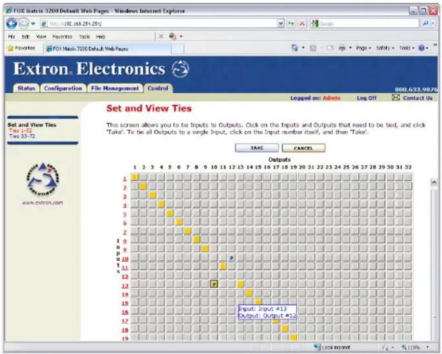
Figure 66. User Control Ties Page
The page consists of a matrix of input (rows) and output (columns) buttons of two colors:
• The amber buttons indicate ties.
• The gray buttons indicate no ties.
TIP: If you lose track of the input and output associated with a specific button, hover the mouse over the button for a moment. As shown on figure 66, a field pops up that identifies the input and output numbers for that button.
Creating or deleting a tie
Make or break a tie as follows:
-
Move the mouse over the matrix of input and output selection buttons. Click a button to:
-
Create a pending tie of the input and output associated with that button
- Create a pending untie of the input and output associated with that button
A "P" (for pending) appears in the button.
NOTES:
-
You can make up to of 30 connections with a single Take command (step 2).
• To tie an input to all outputs, click the input number for that input. -
Click the Take button to make the configuration changes or the Cancel button to abandon the configuration changes.
Maintenance and Modifications
This section provides procedures for maintaining and modifying the FOX matrix switchers, including:
- Mounting the Switcher
• Battery and Power Precautions - Removing and Installing an I/O Board or Blank Panel
- Removing and Installing a Power Supply Module
- Removing and Installing a Fan Module
- Removing and Installing Button Labels
ATTENTION:
Mounting the Switcher
The FOX Matrix 3200 is housed in a rack-mountable, 4U high metal enclosure with mounting flanges for standard 19-inch wide racks. The FOX Matrix 7200 is in an 8U high enclosure.
UL Guidelines
The following Underwriters Laboratories (UL) guidelines pertain to the installation of the matrix switcher into a rack.
- Elevated operating ambient temperature — If the equipment is installed in a closed or multi-unit rack assembly, the operating ambient temperature of the rack environment may be greater than room ambient. Therefore, consider installing the equipment in an environment compatible with the maximum ambient temperature specified by Extron (Tma = +32 to +122 °F [0 to +50 °C]).
- Reduced air flow — Installation of the equipment in a rack should be such that the amount of air flow required for safe operation of the equipment is not compromised.
- Mechanical loading — Mount the equipment in the rack so that uneven mechanical loading does not create a hazardous condition.
- Circuit overloading — Consider the connection of the equipment to the supply circuit and the effect that overloading of the circuits might have on overcurrent protection and supply wiring. Use appropriate consideration of equipment nameplate ratings when addressing this concern.
- Reliable earthing (grounding) — Reliable earthing of rack-mounted equipment should be maintained. Particular attention should be given to supply connections other than direct connections to the branch circuit (such as the use of power strips).
FOX Matrix 3200 and 7200 Switchers • Maintenance and Modifications 111
Mounting Instructions
If desired, rack mount the switcher as follows:
- Insert the unit into the rack, aligning the mounting bracket holes with those in the rack.
- Secure the switcher to the rack using the supplied bolts.
Battery and Power Precautions
The matrix switcher is provided with a permanently installed (factory-soldered in place) lithium battery. The battery maintains the real time clock in the event of power failure or extended storage periods and does not affect the normal operation of the switcher. If the battery becomes ineffective, return the switcher to Extron for repair.

WARNING: There is a danger of explosion if the battery is incorrectly replaced. Do not attempt to remove or replace the internal battery.
Removing and Installing an I/O Board or Blank Panel

WARNING: The FOX matrix switchers fiber optic I/O boards output continuous invisible light (Class 1 rated), which may be harmful to the eyes; use with caution.
- Do not look into the fiber optic cable connectors or into the fiber optic cables themselves.
- Plug the attached dust cap into the optical transceiver when the fiber optic cable is unplugged.
- As factory configured, the fiber optic I/O boards are either 100 percent singlemode or 100 percent multimode, but you can remove a fiber optic transceiver module (one input and one output) of one transmission mode and replace it with a block of the other transmission mode.
You can mix transmission mode transceiver modules on a fiber optic I/O board, provided that you ensure that each fiber cable and connected devices are the appropriate transmission mode for the transceiver module. Typically, singlemode fiber has a yellow jacket and multimode cable has an orange or aqua jacket.
- For proper cooling and air flow, boards or blank panels should be installed in all locations during normal switcher operations.
See figure 67. The transceiver modules on fiber optic I/O boards and the BNC connectors on SDI/HD-SDI boards are identified as A through H. Each I/O board is identified by the input and output numbers supported by the board position (1 - 8, 9 - 16, and so on).
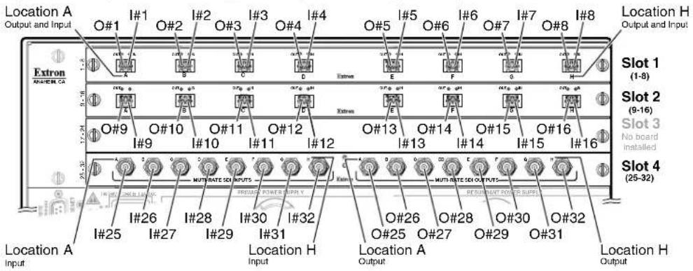
Figure 67. Arrangement of Inputs and Outputs on the I/O Boards
| Slot Inputs and Outputs Slot Inputs and Outputs | ||
| 1 1 through 8 5* 33 through 40 | ||
| 2 9 through 16 6* 41 through 48 | ||
| 3 17 through 24 7* 49 through 56 | ||
| 4 25 through 32 8* 57 through 64 | ||
| 9* 65 through 72 | ||
* FOX Matrix 7200 only
Locations A through H correspond to the input and output numbers identified by the board position numbers. (For example, the input and output numbers supported by the I/O board in location 9 - 16 (slot 2) are as follows: A = 9, B = 10, C = 11, D = 12, E = 13, F = 14, G = 15, and H = 16.)
On the fiber optic I/O boards, locations A through H correspond to the transceiver modules, each of which includes an input and an output. Therefore, locations A through H are numbered from left to right.
On the 3G/SDI/HD-SDI I/O boards, inputs and outputs are grouped separately, with inputs A through H on the left and outputs A through H on the right.
ATTENTION:
NOTE: The I/O boards are hot-swappable. You do not need to power down the switcher to remove or install an I/O board.
Removing an I/O Board or Blank Panel
Remove an I/O board or blank panel as follows:
- For an I/O board, disconnect any connected cables.
- Rotate the left and right knurled knobs to completely loosen the captive screws (see figure 68).
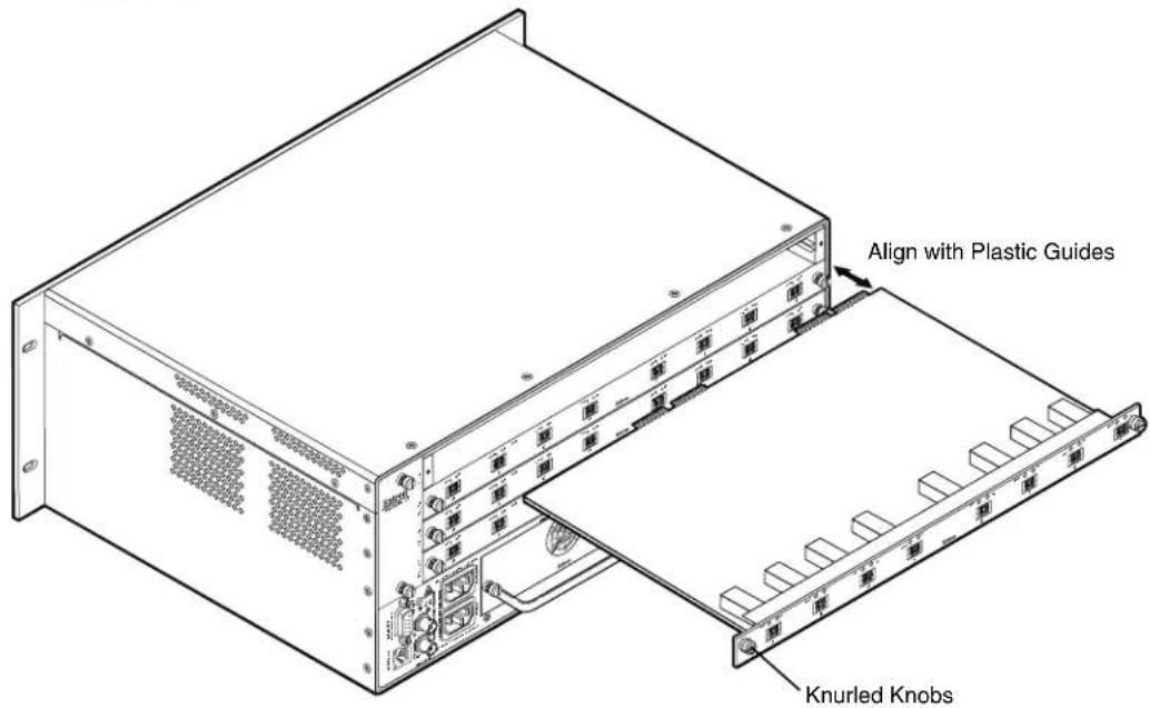
Figure 68. I/O Board Replacement
- Gently pull on the screws to loosen the board or panel from the backplane.
- Slide the board or panel out of the chassis.
- Place the removed board on an antistatic surface or in an antistatic container.
Installing an I/O board or blank panel
Install an I/O board or blank panel as follows:
- For an I/O board, orient the board to be installed so that transceiver module A (fiber board) or input BNC A (SDI/HD-SDI board) is on the left and transceiver module or output BNC H is on the right as you face the rear of the switcher.
- For an I/O board, align the board with the left and right chassis guides (see figure 68).
- Gently slide the board or blank panel into the enclosure. For an I/O board, slide the board toward the front panel until it meets resistance.
- Gently seat the board or panel in the backplane.
- Use a screwdriver to tighten the left and right captive screws to secure the board or panel in place.
Removing and Installing a Power Supply Module
The two (primary and redundant) power supply modules are identical. Each power supply module has a 2-color status LED, visible on the rear panel, that indicates the status of the power supply outputs. If the LED is lit green, the power supply is operating normally. If the LED is lit red, the supply has failed and should be replaced at the earliest opportunity.
NOTE: The power supply modules are hot-swappable. Either power supply can be removed of installed without powering down the switcher.
Removing the Power Supply Module
Remove a power supply module as follows:
- Rotate the left and right knurled knobs to completely loosen the captive screws.
- Gently pull on the handle to loosen the power supply from the backplane (see figure 69).
- Slide the power supply out of the chassis.
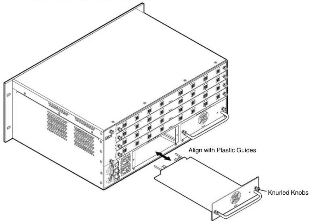
Figure 69. Power Supply Replacement
Installing a Power Supply Module
Install a power supply module as follows:
- Orient the power supply module to be installed with the LED to the right.
- Align the flanges on the power supply module with the left and right power supply guides (see figure 69).
- Gently slide the power supply into the enclosure until the module meets resistance.
- Gently seat the power supply in the backplane.
- Use a screwdriver to tighten the left and right knurled knobs/captive screws to secure the power supply in place.
FOX Matrix 3200 and 7200 Switchers • Maintenance and Modifications 115
Removing and Installing a Fan Module
The FOX Matrix 3200 has one replaceable fan module; the FOX Matrix 7200 has two identical fan modules. If a fan fails, it should be replaced at the earliest opportunity.
NOTE The fan modules are hot-swappable; they can be removed or installed without powering down the switcher.
Removing a Fan Module
- Rotate the top and bottom knurled knobs to completely loosen the captive screws (see figure 70).
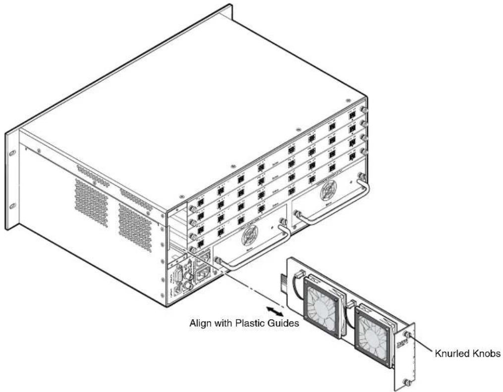
Figure 70. Fan Replacement
- Gently pull on the screws to loosen the fan from the backplane.
- Slide the fan out of the chassis.
Installing a Fan Module
- Orient the fan to be installed so that the printing on the back of the panel is right-side up.
- Align the flanges on the fan with the top and bottom fan guides (see figure 70).
- Gently slide the fan into the enclosure until the fan meets resistance.
- Gently seat the fan in the backplane.
- Use a screwdriver to tighten the top and bottom captive screws to secure the fan in place.
Removing and Installing Button Labels
Figure 72 on the next page provides strips of blank button labels. If desired, copy them or cut them out, write button information in each button area as desired, and put them in the windows of the input or output buttons. You can also create labels using the Button Label Generator software (see Button Label Generator Program on page 93).
Installing Labels in the Buttons
Install new labels in the front panel buttons as follows:
- Remove the button from the matrix switcher; use a small, flat bladed screwdriver such as an Extron Tweeker to gently pry a button out from the front panel (see figure 71).
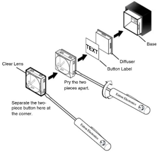
flowchart
graph TD
    A["Clear Lens"] --> B["Pry the two pieces apart."]
    B --> C["Text"]
    C --> D["Base"]
    C --> E["Diffuser Button Label"]
    E --> F["Exter Electronics"]
    B --> G["Separate the two-piece button here at the corner."]
Figure 71. Illuminated Button Label Replacement
- Locate the notch in the corner of one side of the clear button cap lens.
- Separate the white backing (diffuser) from the clear button cap (lens); insert the blade of the small screwdriver into the corner notch and gently twist the blade.
- Save the translucent, white diffuser, but remove the text label insert from the transparent button cap lens.
- Insert the replacement button label into the button cap. Check for correct label orientation.
- Align the white diffuser plate with the cap (lens). The bumps on the diffuser plate should be aligned (top and bottom) with the notches on the clear button cap. Firmly snap it into place.
- Align the tabs on the base of the matrix switcher with the notches on the diffuser plate. Gently, but firmly, press the reassembled button into place on the front panel of the switcher.
- Repeat steps 1 to 7 as needed to relabel other buttons.

natural_image
Grid of empty rectangular boxes arranged in 4x4 pattern (no text or symbols)Figure 72. Button Label Blanks
Ethernet Connection
This section provides a high level discussion of the Ethernet connection to the switcher and a primer on the subject of subnetting. Topics that are covered, include:
- Ethernet Link
- Subnetting — A Primer
Ethernet Link
The rear panel Ethernet connector on the FOX matrix switcher can be connected to an Ethernet LAN or WAN. This connection makes SIS control of the switcher possible using a computer connected to the same LAN.
Ethernet Connection
The Ethernet cable can be terminated as a straight-through cable or a crossover cable and must be properly terminated for your application (see figure 10 on page 14).
- Crossover cable — Direct connection between the computer and the FOX matrix switcher
- Patch (straight-through) cable — Connection of the FOX matrix switcher to an Ethernet LAN
Default IP Address
To access the FOX matrix switcher via the LAN port, you need the IP address of the switcher. If the address has been changed to an address comprised of words and characters, you can determine the actual numeric IP address using the ping utility. If the address has not been changed, the factory-specified default is 192.168.254.254.
Ping can also be used to test the Ethernet link to the FOX matrix switcher.
Pinging to Determine the Extron IP Address
The ping utility is available at the Command prompt. Ping tests the Ethernet interface between the computer and the FOX matrix switcher. Ping can also be used to determine the actual numeric IP address from an alias and to determine the web address.
Ping the switcher as follows:
- On the Windows task bar, click on Start > Run.
- At the Open prompt, type command.
- Click the OK button.
- At the Command prompt, type ping {IP address} and then press
. The computer returns a display similar to the one shown in figure 73.
C:\>ping 192.168.254.254
Pinging 192.168.254.254 with 32 bytes of data:
Reply from 192.168.254.254: bytes=32 time<10ms TTL=128
Reply from 192.168.254.254: bytes=32 time<10ms TTL=128
Reply from 192.168.254.254: bytes=32 time<10ms TTL=128
Reply from 192.168.254.254: bytes=32 time<10ms TTL=118
Ping statistics for 192.168.254.254:
    Packets: Sent = 4, Received = 4, Lost = 0 (0% loss),
Approximate round trip times in milli-seconds:
    Minimum = 0ms, Maximum = 0ms, Average = 0ms
Figure 73. Typical Ping Response
The line Pinging ... reports the actual numeric IP address, regardless of whether you entered the actual numeric IP address or an alias name.
Pinging to Determine the Web IP Address
The ping utility has a modifier, -a, that directs the command to return the web address rather than the numeric IP address.
At the Command prompt, type ping -a {IP address} and then press
Configuring the Switcher for Network Use via the ARP Command
The ARP (address resolution protocol) command tells your computer to associate the MAC (media access control) address of the FOX matrix switcher with the assigned IP address. You must then use the ping utility to access the controller, at which point the IP address of the controller is reconfigured.
Use ARP to configure the IP address as follows:
- Obtain a valid IP address for the FOX matrix switcher from your network administrator.
- Obtain the MAC address (UID #) of the FOX matrix switcher from the label on its rear panel. The MAC address should have this format: 00-05-A6-xx-xx-xx.
- If the FOX matrix switcher has never been configured and is still set for factory defaults, proceed to step 4. If not, perform a mode 4 system reset and then proceed to step 4. For detailed information on reset modes, see Performing Soft System Resets (Resets 3, 4, and 5) on page 45.
NOTE: The FOX matrix switcher must be configured with the factory default IP address (192.168.254.254) before the ARP command is executed, as described below.
- At the PC, access the Command prompt (see Pinging to Determine the Extron IP Address on the preceding page, steps 1 through 3), then enter the arp -s command. Type in the desired new IP address for the unit (obtained in step 1) and the MAC address of the unit (from the rear panel of the unit), for example, arp -s 192.168.254.254 00-05-A6-03-69-B0 and then press
.
The computer returns the command prompt (C:).
After you issue the arp -s command, the controller changes to the new address and starts responding to the ping requests to the new address, as described in the next step.
NOTE: You must ping the FOX matrix switcher for the IP address change to take place. The response should show the new IP address, as shown in figure 74.
- Execute a ping command by entering ping followed by a space and the new IP address at the command prompt. For example:
ping 192.168.254.254
C:\>ping 192.168.254.254
Pinging 192.168.254.254 with 32 bytes of data:
Reply from 192.168.254.254: bytes=32 time<10ms TTL=128
Reply from 192.168.254.254: bytes=32 time<10ms TTL=128
Reply from 192.168.254.254: bytes=32 time<10ms TTL=128
Reply from 192.168.254.254: bytes=32 time<10ms TTL=118
Ping statistics for 192.168.254.254:
    Packets: Sent = 4, Received = 4, Lost = 0 (0% loss),
Approximate round trip times in milli-seconds:
    Minimum = 0ms, Maximum = 0ms, Average = 0ms
Figure 74. Ping with New Address
NOTE: You can reconnect using either Telnet or a web browser to verify that the update was successful.
- After verifying that the IP address change was successful, enter and issue the arp -d command at the Command prompt. For example:
arp -d 192.168.254.254 removes 192.168.254.254 from the ARP table or
arp -d* removes all static IP addresses from the ARP table.
Connecting as a Telnet Client
The Microsoft Telnet utility is available from the Command prompt. Telnet allows you to input SIS commands to the FOX matrix switcher from the PC via the Ethernet link and the LAN.
Access the Command prompt and start Telnet as follows:
- On the Windows task bar, click Start > Run.
- At the Open prompt, type command.
- Click the OK button.
- At the Command prompt, type Telnet and then press
. The computer returns a display similar to the one shown in figure 75.
Microsoft (R) windows 2000 (TM) Version 5.0 (Build 2195)
Welcome to Microsoft Telnet Client
Telnet Client Build 5.00.99203.1

Escape Character is 'CTRL+']

Microsoft Telnet>
Figure 75. Telnet Window
Telnet Tips
It is not the intention of this guide to detail all of the operations and functionality of Telnet; however, some basic level of understanding is necessary for operating the FOX matrix switcher via Telnet.
Open
Connect to the FOX matrix switcher using the Open command. Once you are connected to the switcher, you can enter the SIS commands the same as you would if you were using the RS-232 or RS-422 link.
Connect to the FOX matrix switcher as follows:
- At the Telnet prompt, type open {IP address} and then press
.
If the switcher is password protected, Telnet displays the password prompt.
NOTE: The factory configured passwords for all accounts on this device have been set to the device serial number. Passwords are case sensitive.
If the switcher is not password protected, no further prompts are displayed until you break or disconnect the connection to the matrix switcher.
- If necessary, at the password prompt, type the appropriate password and then press
.
Connection to the switcher via the Ethernet can be password protected. There are two levels of password protection: administrator and user. A person logged on as an administrator has full access to all matrix switcher switching capabilities and editing functions. Users can create ties, set mutes, and view all settings with the exception of passwords. By default, the FOX matrix switcher is shipped with both passwords set to {carriage return}.
Once you are logged in, the switcher returns either Login Administrator or Login User. No further prompts are displayed until you break or disconnect the connection to the FOX matrix switcher.
Escape character and Esc key
When Telnet is first started, the utility advises that the Escape character is 'Ctrl+'. Many SIS commands include the keyboard
The Telnet Escape character is a key combination, the
The Escape key is the
Local echo
Once connected to the FOX matrix switcher, by default, Telnet does not display your keystrokes on the screen. SIS commands are typed in blindly and only the SIS responses are displayed on the screen. To command Telnet to show keystrokes, at the Telnet prompt, type set local_echo and then press
With local echo turned on, keystrokes and the responses of the switcher are displayed on the same line. For example: 1*1! In1 Out1 All, where 1*1! is the SIS command and In1 Out1 All is the response.
With local echo turned on, all keystrokes are displayed, even those that should be masked, such as the password entry. For example, when entering a password with local echo turned on, you see a display such as a*d*m*i*n*, where admin is the keyed in password and ***** is the masked response.
You can turn off local echo by typing unset local_echo and then pressing
Set carriage return-line feed
Unless commanded otherwise, Telnet transmits a line feed character only (no carriage return) to the connected switcher when you press the
Close
To close the link to the switcher, access the Telnet prompt by typing the Escape character (
Help
For Telnet command definitions, at the Telnet prompt, type ? and then press
Quit
Exit the Telnet utility by typing quit and then pressing
Subnetting — A Primer
It is not the purpose of this guide to describe TCP/IP protocol in detail. However, some understanding of TCP/IP subnetting (a subnet is a subset of a network — a set of IP devices that have portions of their IP addresses in common) is necessary in order to understand the interaction of the FOX matrix switcher and the mail server gateway. To understand subnetting at the level required to install and operate the FOX matrix switcher, you must understand the concepts of a gateway, local and remote devices, IP addresses and octets, and subnet masks and octets.
Gateways
The FOX matrix switcher can communicate with the email server that the switcher uses for email notification directly (if they are on the same subnet) or the communication can be routed via a gateway (a computer that provides a link between different subnets).
Local and Remote Devices
The local and remote devices are defined from the point of view of the function being described. In this guide, subnetting is an issue when you are using the controlling PC to set TCP/IP and email values in the matrix switcher (see IP Settings / Options Window on page 78 and Email Settings Page on page 104). When you are setting up the variables for email notification, which may include subnetting, the matrix switcher is the local device and the email server is the remote device.
IP Addresses and Octets
Valid IP addresses consist of four 1-, 2-, or 3-digit numeric subfields, properly called "octets," separated by dots (periods) (see figure 76). Each octet can be numbered from 000 through 255. Leading zeroes, up to three digits total per octet, are optional. Values of 256 and above are invalid.
$$ \underbrace {1 9 2 . 1 6 8 . 2 5 4 . 2 5 4} _ {\text { Octets }} $$
Figure 76. Typical IP Address
Subnet Masks and Octets
The subnet mask (see figure 77) is used to determine whether the local and remote devices are on the same subnet or different subnets. The subnet mask consists of four numeric octets separated by dots. Each octet can be numbered from 000 through 255. Leading zeroes, up to three digits total per octet, are optional. Each octet typically contains either 255 or 0. The octets determine whether or not the same octets of two IP addresses will be compared when determining if two devices are on the same subnet.
255 indicates that this octet will be compared between two IP addresses.
0 indicates that this octet will not be compared between two IP addresses.
255.255.0.0 Typical Subnet Mask: Octets
Figure 77. Typical Subnet Mask
Determining Whether Devices Are on the Same Subnet
To determine the subnet, the IP address of the local device is compared to the IP address of the remote device (see figure 78). The octets of each address are compared or not compared, depending on the value in the related subnet mask octet.
- If a subnet mask octet contains the value 255, the related octets of the IP addresses of the local device and the remote device are unmasked.
Unmasked octets are compared (indicated by ? in figure 78).
- If the subnet mask octet contains the value 0, the related octets of the IP addresses of the local device and remote device are masked.
Masked octets are not compared (indicated by X in figure 78).
If the unmasked octets of the two IP addresses match (indicated by = in figure 78, example 1), the two addresses are on the same subnet.
If the two unmasked fields do not match (indicated by in figure 78, example 2 and example 3), the addresses are not on the same subnet.
| Example 1 Example 2 | Example 3 | ||
| Local IP Address: | 192.168.254.254 | 192.168.254.254 | 192.168.254.254 |
| Subnet Mask: | 255.255.0.0 (?.?.X.X) | 255.255.0.0 (?.?.X.X) | 255.255.0.0 (?.?.X.X) |
| Remote IP Address: | 192.168.2.25 | 190.190.2.25 | 192.190.2.25 |
| Match?: | =.=.X.X — Match(Same subnet) | ≠.≠.X.X — No match(Different subnet) | =.=.X.X — No match(Different subnet) |
Figure 78. Comparing the IP Addresses of the Local and Remote Devices
Extron Warranty
Extron Electronics warrants this product against defects in materials and workmanship for a period of three years from the date of purchase. In the event of malfunction during the warranty period attributable directly to faulty workmanship and/or materials, Extron Electronics will, at its option, repair or replace said products or components, to whatever extent it shall deem necessary to restore said product to proper operating condition, provided that it is returned within the warranty period, with proof of purchase and description of malfunction to:
USA, Canada, South America, and Central America:
Extron Electronics
1230 South Lewis Street
Anaheim, CA 92805
U.S.A.
Asia:
Extron Asia Pte Ltd
135 Joo Seng Road, #04-01
PM Industrial Bldg.
Singapore 368363
Singapore
Japan:
Extron Electronics, Japan
Kyodo Building, 16 Ichibancho
Chiyoda-ku, Tokyo 102-0082
Japan
Europe:
Extron Europe
Hanzeboulevard 10
3825 PH Amersfoort
The Netherlands
China:
Extron China
686 Ronghua Road
Songjiang District
Shanghai 201611
China
Middle East:
Extron Middle East
Dubai Airport Free Zone
F13, PO Box 293666
United Arab Emirates, Dubai
Africa:
Extron South Africa
South Tower
160 Jan Smuts Avenue
Rosebank 2196, South Africa
This Limited Warranty does not apply if the fault has been caused by misuse, improper handling care, electrical or mechanical abuse, abnormal operating conditions, or if modifications were made to the product that were not authorized by Extron.
NOTE: If a product is defective, please call Extron and ask for an Application Engineer to receive an RA (Return Authorization) number. This will begin the repair process.
USA: 714.491.1500 or 800.633.9876 Asia:
65.6383.4400
Europe: 31.33.453.4040 or 800.3987.6673
Japan: 81.3.3511.7655
Africa: 27.11.447.6162
Middle East: 971.4.299.1800
Units must be returned insured, with shipping charges prepaid. If not insured, you assume the risk of loss or damage during shipment. Returned units must include the serial number and a description of the problem, as well as the name of the person to contact in case there are any questions.
Extron Electronics makes no further warranties either expressed or implied with respect to the product and its quality, performance, merchantability, or fitness for any particular use. In no event will Extron Electronics be liable for direct, indirect, or consequential damages resulting from any defect in this product even if Extron Electronics has been advised of such damage.
Please note that laws vary from state to state and country to country, and that some provisions of this warranty may not apply to you.
- Fiber Optic Matrix Switchers
- FOX Matrix 3200,
- FOX Matrix 7200
- Safety Instructions
- Safety Instructions • English
- Trademarks
- FCC Class A Notice
- Battery Notice
- Class 1 Laser Product
- Conventions Used in this Guide
- Notifications
- Software Commands
- Specifications Availability
- Extron Glossary of Terms
- Contents
- Introduction.... 1
- Installation....7
- Operation....18
- Programming Guide....52
- Matrix Software....71
- HTML Operation 95
- Maintenance and Modifications .... 111
- Ethernet Connection 119
- Introduction
- About the FOX Matrix Switchers
- NOTES:
- Fiber Cable Transmission Modes
- Features
- Cross-format compatibility —
- Setup and Installation Checklist
- Get Ready
- Configure the Matrix Switcher
- Perform Physical Installation
- Ancillary Operations
- Rear Panel Boards, Cabling, and Features
- ATTENTION:
- I/O Boards
- Fiber optic I/O board LED indications
- 3G/HD/SD-SDI boards
- Remote Port
- Ethernet Connection
- Cabling
- RJ-45 connector wiring
- Reset Button and LED
- Switch Reference Connections
- Power Supply Modules and Indicator LEDs
- Cooling Fan Assemblies
- Front Panel Configuration Port
- Operation
- Front Panel Controls and Indicators
- Input and Output Buttons
- Control Buttons
- Power Indicators
- Button Icons
- Rear Panel Power Indicators
- A Primary and Redundant Power Supply LEDs —
- Front Panel Operations
- Definitions
- Power
- Creating a Configuration
- Example 1: Create a set of ties
- Example 2: Add a tie to a set of ties
- Confirm the change: Press and release the Enter button.
- Example 3: Remove a tie from a set of ties
- Select the output: Press and release the Output 4 button.
- Viewing the Configuration
- Example 4: Viewing ties
- Select an input: Press and release the Input 5 button.
- Exit View-only mode: Press and release the View button
- I/O Grouping
- Example 5: Grouping inputs and outputs
- Using Presets
- Example 6: Saving a preset
- Example 7: Recalling a preset
- Muting and Unmuting Outputs
- Example 8: Muting and unmuting an output
- Locking the Front Panel (Executive Mode)
- Performing a System Reset from the Front Panel
- Background Illumination
- Selecting the Rear Panel Remote Port Protocol and Baud Rate
- Reset Operations
- Performing Soft System Resets (Resets 3, 4, and 5)
- Performing a Hard Reset (Reset 1)
- Troubleshooting
- Configuration Worksheets
- Worksheet Example 1: System equipment
- Figure 28. Worksheet Example 1: System Equipment
- Worksheet Example 2: Daily Configuration
- Figure 29. Worksheet Example 2: Daily Configuration
- Worksheet Example 3: Test configuration
- Programming Guide
- Serial Ports
- Ethernet (LAN) Port
- Default IP addresses
- Establishing a Connection
- Connection Timeouts
- Number of Connections
- Using Verbose Mode
- Host-to-Switcher Instructions
- Switcher-initiated Messages
- Password:
- Switcher Error Responses
- Using the Command and Response Tables
- Command and Response Table for SIS Commands
- Symbol Definitions
- Command and Response Table for IP- and SNMP-Specific SIS Commands
- SNMP setup commands
- Unit contact name and location
- Special Characters
- Matrix Software
- Matrix Switchers Control Program
- Software Operation via Ethernet
- Ethernet protocol settings
- Software Operation via a Serial Port
- Installing the Software
- TIPS:
- Using the Matrix Switcher Control Software
- IP Settings / Options window
- Address and Name fields
- Hardware Address field
- Use DHCP check box
- Date, Time (local), and GMT (offset) fields
- Sync Time to PC button
- Use Daylight Saving check box
- Administrator Password and User Password fields
- Mail Server IP Address field
- Mail Server Domain Name field
- E-mail Addressee fields
- Miles Standish
- Figure 40. Typical FOX Matrix Switcher Email
- Updating the Firmware
- Ethernet-connected firmware upload
- Serial-port-connected firmware upload
- Uploading HTML Files
- Windows Buttons, List Boxes, and Trash Can
- Windows menus
- File menu
- Tools menu
- Preferences menu
- Master-Reset selection
- Using Emulation Mode
- Using the Help System
- Button Label Generator Program
- Installing the Button Label Generator Software
- Using the Button Label Generator Software
- HTML Operation
- Opening the Embedded Web Pages
- Status Tab
- System Status Page
- Input Link page
- Configuration Tab
- System Settings Page
- IP Settings fields
- Unit Name field
- DHCP radio buttons
- IP Address field
- Gateway IP Address field
- Subnet Mask field
- MAC Address field
- Firmware field
- Model field
- Part Number field
- Date/Time Settings panel
- NOTES
- Passwords Page
- Resetting a password
- Email Settings Page
- Mail IP Address field
- Domain Name field
- Setting up SMTP authorization
- Deselecting SMTP authorization
- Email Address fields
- SNMP Settings Page
- SNMP General Settings fields
- SNMP Manager (Trap Target) fields
- Firmware Upgrade Page
- File Management Tab
- File Management Page
- Control Tab
- Set and View Ties Page
- Creating or deleting a tie
- Maintenance and Modifications
- Mounting the Switcher
- UL Guidelines
- Mounting Instructions
- Battery and Power Precautions
- Removing and Installing an I/O Board or Blank Panel
- Removing an I/O Board or Blank Panel
- Installing an I/O board or blank panel
- Removing and Installing a Power Supply Module
- Removing the Power Supply Module
- Installing a Power Supply Module
- Removing and Installing a Fan Module
- Removing a Fan Module
- Installing a Fan Module
- Removing and Installing Button Labels
- Installing Labels in the Buttons
- Ethernet Link
- Default IP Address
- Pinging to Determine the Extron IP Address
- Pinging to Determine the Web IP Address
- Configuring the Switcher for Network Use via the ARP Command
- Connecting as a Telnet Client
- Telnet Tips
- Open
- Escape character and Esc key
- Local echo
- Set carriage return-line feed
- Close
- Help
- Quit
- Subnetting — A Primer
- Gateways
- Local and Remote Devices
- IP Addresses and Octets
- Subnet Masks and Octets
- Determining Whether Devices Are on the Same Subnet
- Extron Warranty
- USA, Canada, South America, and Central America:
- Asia:
- Japan:
- Europe:
- China:
- Middle East:
- Africa:
Brand : Extron
Model : FOX Matrix 7200
Category : Network switch