
PSW710S - Wall mount Pyle - Free user manual and instructions
Find the device manual for free PSW710S Pyle in PDF.


User questions about PSW710S Pyle
0 question about this device. Answer the ones you know or ask your own.
Ask a new question about this device
Download the instructions for your Wall mount in PDF format for free! Find your manual PSW710S - Pyle and take your electronic device back in hand. On this page are published all the documents necessary for the use of your device. PSW710S by Pyle.
USER MANUAL PSW710S Pyle
Thank you for choosing our product

Warning
This product contains small items that could be a choking hazard if swallowed. Keep these items away from young children!
I. Make sure these instructions are read and completely understood before attempting installation. If you are unsure of any part of this installation, contact a professional installer for assistance.
2. The wall or mounting surface must be capable of supporting the combined weight of the mount and the display; otherwise the structure must be reinforced
3. Safety gear and proper tools must be used. A minimum of two people are required for this installation. Failure to use safety gear can result in property damage, serious injury or death.

LCD WALL MOUNT
Installation Instructions
Item No.:PSW710S

natural_image
Technical line drawing of a mechanical assembly with two views (top and side), no text or symbols present.• TV Size Range: 14"3-7"
• Maximum Weight Capacity: 25kg/55lbs
- Adjustable angle: 515°
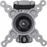
- Mounting Pattern: VESA 75, VESA 100, VESA 200x100
or VESA200X200
www pyleaudio com.
MADE IN CHINA

CAUTION
This product was designed to be installed on wood stud walls and solid concrete walls. Before installing make sure the supporting surface will support the combined load of the equipment and hardware. Never exceed the Maximum Load Capacity. This product is intended for indoor use only. Use of this product outdoors could lead to product failure or personal injury.
Hardware Kit:

Plastic Cover

| ID Description | ||
| A1 | 4 | M × m m B 4 |
| A2 | 4 | M5× mm B25 olt |
| A3 | 4 | M6× mm B25 olt |
| A4 | 4 | M8× mm B16 olt |
| B1 | 4 | Drywall bolt |
| B2 | 4 | Concrete Anchor |
| B3 | 4 | Washer |
| C1 | 2 | Fastener |
| C2 | 2 | Spacer |
2 5 o l t
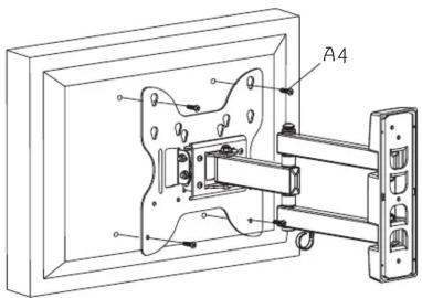
If your TV's mounting holes can't match bolt (A1, A1, A3), you can use bolt (A4)
Attaching TV plate To Screen
Attach TV paden using four screws(A4). Tighten bolts firmly. Do not overtighten.
Lift the screen and hook spacers(C1) on to the wall plate. Fasten the bottom of the screen to wall plate using two selected bolts(A1,A2,A3) and two spacers(C2). Tighten bolts firmly. Do not overtighten.

Part Ia-Wood Stud Mounting
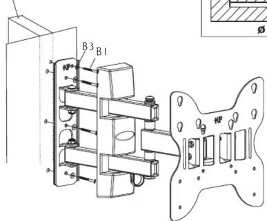
Use wall plate as a template, make sure it is level, and mark four mounting holes along the center line of the wood studs. Drill four 3/16(4.5mm) dia- holes 60mm deep. Level wall plate and attach to wall with four long bolts(B1) and four washers(B3). Tighten bolts firmly. Do not overtighten.
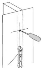
Stud finder

natural_image
Technical line drawing of a mechanical assembly with a tool inserted into a bracket (no text or symbols)
Wood stud
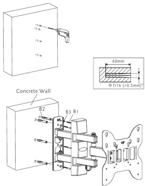
Part Ib-Concrete Wall Mounting
Level wall plate and use wall as a template to mark four holes. Drill four 7/16" (10.5mm) dia. holes 60mm deep. Insert four anchors(B2) into holes and secure wall plate with four long bolts(B1) and four washers(B3). Tighten bolts firmly. Do not overtighten .
Part 2-Attaching Screen to TV plate
Select the small(A1), medium(A2) or large(A3) bolts. Attach two spacers (C1) to the top two mounting holes on the back of the screen using two of the selected bolts. Tighten bolts firmly. Do not overtighten.
A: VESA 75 (75mm x 75mm)
B: VESA 100 (100mm x 100mm)
C: VESA 200 (100mm x 200mm)
D: VESA 200 (200mm x 200mm)

flowchart
graph TD
    A["Component 1"] --> B["Switch"]
    C["Component 2"] --> B
    B --> D["Output"]
    E["Component 3"] --> F["Switch"]
    G["Component 4"] --> F
    F --> H["Output"]
    I["Component 5"] --> J["Switch"]
    K["Component 6"] --> J
    J --> L["Output"]

Brand : Pyle
Model : PSW710S
Category : Wall mount