
Multisensor trio - Door/window sensor Zipato - Free user manual and instructions
Find the device manual for free Multisensor trio Zipato in PDF.


| Product Type | Door/Window Sensor with additional sensors |
| Brand | Zipato |
| Model | Multisensor trio |
| Wireless Protocol | Z-Wave |
| Dimensions (Sensor) | Approx. 70 x 30 x 20 mm |
| Weight (Sensor) | Approx. 30 g (including battery) |
| Power Supply | 1 x CR123A 3V battery |
| Battery Life | Up to 2 years under normal use |
| Communication Range | Up to 30 meters indoors (may vary) |
| Operating Temperature | 0°C to 40°C |
| Operating Humidity | 5% to 85% non-condensing |
| Main Functions | Open/close detection, temperature measurement, light sensor |
| Installation | Adhesive tape or screws (included) |
| Maintenance | Clean with a dry cloth; replace battery when low |
| Safety | Designed for indoor use only; keep away from water and extreme heat |
| Spare Parts / Repairability | Battery replaceable; sensor unit not user-serviceable |
| Certifications | CE, FCC |
| Compatibility | Zipato Z-Wave hub or any Z-Wave certified controller |
Frequently Asked Questions - Multisensor trio Zipato
User questions about Multisensor trio Zipato
0 question about this device. Answer the ones you know or ask your own.
Ask a new question about this device
Download the instructions for your Door/window sensor in PDF format for free! Find your manual Multisensor trio - Zipato and take your electronic device back in hand. On this page are published all the documents necessary for the use of your device. Multisensor trio by Zipato.
USER MANUAL Multisensor trio Zipato
Zipato and the Zipato logo are registered Trademarks. All other product names mentioned herein may be trademarks or registered trademarks of their respective companies.
NOTICE
Although Zipato has attempted to ensure the accuracy of the content of this manual, it is possible that this document may contain technical inaccuracies, typographical, or other errors. Zipato assumes no liability for any error in this publication, and for damages, whether direct, indirect, incidental, and consequential or otherwise, that may result from such error, including, but not limited to loss of data or profits.
Zipato provides this publication "as is" without warranty of any kind, either express or implied, including, but not limited to implied warranties of merchantability or fitness for a particular purpose. The published information in the manual is subject to change without notice.Zipato reserves the right to make changes in the product design, layout, and driver revisions without notification to its users. This version of the Installation guide supersedes all previous versions.
ELECTROMAGNETIC COMPATIBILITY
In proper state and when operated properly, the product complies with all the requirements in respect of interference radiation according to EN 301 489-17, EN 301 489-1 and EN 300 328. The connections conducting HF signals must neither be manipulated nor damaged.
→ TAKE CARE OF YOUR SAFETY
Display extreme caution when using ladders or steps, please follow manufacturer's instructions. Be careful when using hand and power tools and follow the manufacturer's guidelines when using them. Take care that the correct tools are used. Wear goggles or protective clothing where required.
INTRODUCTION
The Door/Window 3 in 1 sensor provide:
(1) Door/window,
(2) temperature,
(3) illumination 3 in 1 sensor
The sensor consists of two parts; a Detector and a Magnet.
They are designed to be fitted to doors or windows with the Magnet mounted on the opening part and the Detector mounted on the fixed frame. Opening the protected door/window will remove the magnetic field, trigger the detector and generate an alarm condition, (if the system is armed). The sensor can also applied to automatic light control, one scenario is to get the illumination lux level from built in illumination sensors and send a signal to Z-wave switch to turn the light on once we open the door when the room is dark.
Every time when Door/Window trig, the sensor will also send temperature and illumination value as well. Also the temperature will send out the value when temperature changes.
FIGURE 1
Dimensions (unit: mm)
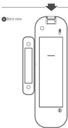
1 Profile view


FEATURES
- [1]Door/window, [2]temperature, [3]illumination 3 in 1 sensor - Adopt newest Z-wave 400series chip, support multichannel operation and higher data rate [9.6/40/100kbps]
☑ Higher output power (+2.5dBm output power as compared to -2.5dBm 300 series Z-wave module) to enhance the communication range
■ 1500mA CR123A Lithium battery to guarantee 3.5 year battery life ■ Built in illumination sensor while applied to light control
- Adopt Z-Wave protocol to secure the success of wireless two way communication
■ With Tamper proof protection
Easy install
■ Low battery indication
Z-Wave V6.02
Z-Wave Certificated No. ZC08-13050003
■ Auto report the open/close status and battery status
LVD: EN60950-1:2006+A11:2009
■ FCC part15.249 / EN300 220-1/ certification
NCC

3 Front view

TECHNICAL SUPPORT
Having trouble installing your new product?
Zipato's website contains the latest user documentation and
software updates for Zipato products and services.
www.zipato.com
CONTACT SUPPORT
WEIGHT DIMENSION (W x H x D)
52 g
Detector 28 x 96 x 23mm
Magnet 10 x 50 x 12 mm
BATTERY
CR123A BATTERY LIFE
1500mA
3.5 years @condition 1
2.5 years @condition 2
ENVIRONMENT
At normal connect situation and trigger 14 times per day [every trigger means close to open or open to close]
一
CONDITION 2. At normal connect situation and trigger 260 times per day (every trigger means close to open or open to close)

zipato
everything under control
MULTISENSOR TRIO
QUICK INSTALLATION GUIDE v1.3
POWER UP PROCEDURE
BATTERY POWER CHECK
When the power up, the device will detect the power level of the battery immediately. If the power level is too low, the LED will continue flash about 5 seconds. Please change another new battery.
NWI
When the power on, the device will check is it already adding to the network? If doesn't, it will auto start the NWI mode. The LED will flash in every second and continue 30 seconds. Until timeout or the device successful to inclusion by controller. You can press the tamper key 3 times to abort the NWI mode.
WAKE
When the power on, the device will wake about 20 seconds. In this duration, the controller can communicate with the device. Normally the device is always sleeping to save the battery energy.
| M1 M2 Description | |
| ON ON Test Mode. | |
| ON OFF Security Mode. | |
| OFF ON Home Automation Mode | |
| OFF OFF | Program Mode. According to the configuration setting NO.5 to set the operation mode. |
OPERATION MODE
There are two operation mode, "Test Mode" and "Normal Mode", the "Test Mode" is for the user test the sensor function when installation.
When the event triggered, normally the LED won't indicated, unless the battery is in the low level, the LED will flash once. And in the "Test Mode" the LED also will light ON one second.
When the event triggered, the device will report the messages to the nodes in the group 1. The messages also include the temperature and the illumination level. The user can switch the report by configuration setting NO. 5. When the event triggered, if the environment luminance is less than the setting of the configuration setting NO. 4, the device will emit the signal to turn ON the lighting equipment, those nodes in the group 2. If the event is door/window close, it will delay about 5 seconds and emit the signal to turn OFF the lighting equipment.
Notice: When the tamper key of the back side is in the released state, the device always in the "Test Mode".
BATTERY INSTALLATION
When the device report the low battery message. The user should replace the battery to new one.
The way to open the front cover please follow below steps.
■ Using a tool like (1) to press 1-1 till hear a click sound
- Hold the front cover and pull back - Hold the front cover and pull up

Replace the new battery and install the cover back.
- Put the front cover bottom to 1-1, and press down.
- Push the front cover top to 2-1.

© CHOOSING A SUITABLE LOCATION
- Don't let the device face the window or the sunlight.
INSTALLATION
In the first time, add the device into the Z-Wave network. First, make sure the primary controller is in the inclusion mode. And then power on the device, just take out the insulation Mylar in the back side of the device. The device will auto start the NWI (Network Wide Inclusion) mode. And it should be included in 5 seconds. You will see the LED light ON one second.
- Let Controller associate with Group 1 of the device, any light switch that intend to be turned on when the device trig please associate to Group 2 of the device.
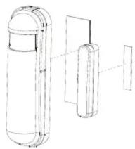
In the accessory pack. There are two types of double coated tape, one is thicker (hereinafter referred to as A tape) and another is thinner (hereinafter referred to as B tape), you can use A tape for the test at the beginning. The right way for A tape installation is stick it to the position below tamper key. The thicker tape won't let the tamper key close, so the sensor will enter the test mode, You may test if installed position is good or not by this way.

After finish the test and decide to fix, then you can remove tape A, and mounting the sensor by using tape B. This will close the tamper key and let the sensor enter normal mode.
ADDING TO Z-WAVE NETWORK
There are two tamper keys in the device, one is in the back side, another is in the front side. They have the same function. Both of them can inclusion, exclusion, reset or association from Z-Wave network.
In the first time, add the device into the Z-Wave network. First, make sure the primary controller is in the inclusion mode. And then power on the device, just take out the insulation Mylar in the back side of the device. The device will auto start the NWI (Network Wide Inclusion) mode. And it should be included in 5 seconds. You will see the LED light ON one second.
INCLUSION:
- Put the Z-Wave Controller in inclusion mode.
- Pressing tamper key three times within 1.5 seconds will enter inclusion mode
■ After inclusion successful, the device will wake to receive the setting command from Z-Wave Controller in about 20 seconds.
EXCLUSION:
Put the Z-Wave Controller in exclusion mode.
- Pressing tamper key three times within 1.5 seconds will enter exclusion mode. Node ID has been excluded.
RESET:
- Pressing tamper key four times within 1.5 seconds and do not release the tamper key when you press it the 4th time, and the LED will turn ON.
After 3 seconds the LED will turn OFF, after that within 2 seconds, release the tamper key. If successful, the LED will light ON one second. Otherwise, the LED will flash once.
■ 3. IDs are excluded and all settings will reset to factory default.
ASSOCIATION:
■ Have Z-Wave Controller entered association mode.
- Pressing tamper key three times within 1.5 seconds will enter
association mode.
Note: The device support 2 groups. The group 1 is for receiving the report message, like triggered event, temperature,
illumination etc. The group 2 is for light control, the device will send the "Basic Set" command to this group.
Including a node ID allocated by Z-Wave Controller means inclusion. Excluding a node ID allocated by Z-Wave Controller means exclusion.
Failed or success in including/excluding the node ID can be viewed from Z-Wave Controller.
Notice: Always Reset a Z-Wave device before trying to add it to a Z-Wave network.
Notice: When the device into NWI mode, the sensor functionality will useless. The NWI mode will timeout after 30 seconds. You can press the tamper key 3 times to abort the NWI mode.
Z-WAVE NOTIFICATION
After the device adding to the network, it will wake-up once per day in default. When it wake-up it will broadcast the "Wake Up Notification" message to the network, and wake-up 10 seconds for receive the setting commands.
The wake-up interval minimum setting is 30 minutes, and maximum setting is 120 hours. And the interval step is 30 minutes. If the user want to wake-up the device immediately, please remove the front cover, and press the tamper key once. The device will wake-up 10 seconds.
Z-WAVE MESSAGE REPORT
DOOR/WINDOW REPORT
When the Door/Window state changed, the device will unsolicited to send the "Sensor Binary Report" to the nodes in the group 1. Sensor Type: Door/Window (0x0A)
Sensor Value: 0x00 is closed, 0xFF is opened.
TAMPER REPORT
When the 2 tamper keys in the device are pressed over 5 seconds. The device will into the alarm state. In that state, if any one of the tamper keys be released, the device will unsolicited to send the "Sensor Binary Report" to the nodes in the group 1.
Sensor Type: Tamper (0x08)
Sensor Value: 0xFF
TEMPERATURE REPORT
When the door/window state changed, the device will unsolicited to send the "Sensor Multilevel Report" to the nodes in the group 1. Sensor Type: Temperature (0x01)
Note: To disable this functionality by setting the configuration setting N0.5, the bit5 of the value to 1.
■ Temperature differential report
This function default is disabled, to enable by setting the configuration setting NO.6 bit6 to 1.
When the temperature plus or minus three degree Fahrenheit (1.67 degree Celsius), the device will report temperature information to the nodes in the group 1. The device will measure the temperature in every 64 seconds. And if the temperature is over 140 degree Fahrenheit (60 degree Celsius), the device also report in each measurement.
ILLUMINATION REPORT
When the door/window state changed, the device will unsolicited to send the "Sensor Multilevel Report" to the nodes in the group 1. Sensor Type: Luminance [0x03]
Note: To disable this functionality by setting the configuration setting N0.5, the bit4 of the value to 1.
MULTISENSOR TRIO
QUICK INSTALLATION GUIDE v1.3
TIMING REPORT
When the power up, the device will detect the power level of the battery immediately. If the power level is too low, the LED will continue flash about 5 seconds. Please change another new battery.
Battery level report: Every 6 hours report once in default. It could be changed by configuration setting NO. 10.
Low battery report: When the battery level is too low, every 30 minutes will report once.
■ Door/window state report: Every 6 hours report once in default. It could be changed by configuration setting NO. 11.
■ Illumination level report: Every 6 hours report once in default. It could be changed by configuration setting NO. 12.
■ Temperature report: Every 6 hours report once in default. It could be changed by configuration setting NO. 13.
Z-WAVE CONFIGURATION SETTINGS
NOTICE: THE DATA SIZE OF THE CONFIGURATION SETTINGS IS 1
| NO. | Name Default | Valid Values | Description | |
| 2 | Basic Set Level | 0xFF | 1~100, 0xFF | Setting the BASIC command value to turn on the light. The 0xFFI-1) means turn on the light. For dimmer equipment 1 to 100 means the light strength. |
| 4 | Light Threshold | 99 0~100 | Setting the illumination threshold to turn on the light. When the event triggered and the environment illumination lower then the threshold, the device will turn on the light. 0 means turn off illumination detected function. And never turn on the light. 1 means darkest. 99 means brightest. 100 means turn off illumination detected function. And always turn on the light. | |
| Notice: In none test mode, only the value in 1 to 99 will enable the illumination detected function and update the illumination value. |
| 5 | Operation Mode | 0 0~127 | Bit0: Reversed.Bit1: Reversed.Bit2: Disable the door/ window function.Bit3: Setting the temperature scale.0: Fahrenheit,1:CelsiusBit4: Disable illumination report after event triggered.Bit5: Disable temperature report after event triggered. | |
| 6 | Multi-Sensor Function Switch | 4 0~127 | Multi-Sensor function switch. Using bit to control.Bit0: Disable magnetic integrate illumination.Bit1: Reserved,always 1.Bit2: Reserved,always 1.Bit3: Reserved.Bit4: Disable delay 5 seconds to turn off the light, when door/ window closed.Bit5: Disable auto turn off the light, after door/window opened to turn on the light.Bit6: Enable temperature monitoring.When this bit enable, the temperature changed 3 degree Fahrenheit, it will report.And also the temperature over 140 degree Fahrenheit, it will report every 64 seconds. | |
| 9 | Turn Off Light Time | 4 4~127 | After turn on the light, setting the delay time to turn off the light. 8 seconds per tick, and minimum time is 32 seconds, default tick is 4 (32 seconds). | |
| 10 | Auto Report Battery Time | 12 1~127 | The interval time for auto report the battery level. 30 minutes per tick and minimum time is 30 minutes, default tick is 12 (6 hours). | |
| 11 | Auto Report Door/ Window State Time | 12 1~127 | The interval time for auto report the door/window state. 30 minutes per tick and minimum time is 30 minutes, default tick is 12 (6 hours). | |
| 12 | Auto Report Illumination Time | 12 1~127 | The interval time for auto report the illumination. 30 minutes per tick and minimum time is 30 minutes, default tick is 12 (6 hours). | |
| 13 | Auto Report Temperature Time | 12 1~127 | The interval time for auto report the temperature. 30 minutes per tick and minimum time is 30 minutes, default tick is 12 (6 hours). |
Z-WAVE CONFIGURATION SETTINGS
Z-WAVE SUPPORTED COMMAND CLASS
COMMAND_CLASS_CONFIGURATION
COMMAND_CLASS_VERSION
COMMAND_CLASS_SENSOR_BINARY_V2
COMMAND_CLASS_ASSOCIATION_V2
COMMAND_CLASS_MANUFACTURER_SPECIFIC_V2
COMMAND_CLASS_WAKE_UP_V2
COMMAND CLASS SENSOR MULTILEVEL V5
COMMAND_CLASS_BATTERY
COMMAND CLASS BASIC
MODELS AND FREQUENCIES
MODELS
EUROPEAN UNION - EU version ph-psm01.eu
| UNITED STATES - US version ph-psm01.us | |
| RUSSIA - RU version ph-psm01.ru | |
| ISRAEL - IS version ph-psm01.is | |
| AUSTRALIA - AU version ph-psm01.au | |
| INDIA - IN version | ph-psm01.in |
The Ground Truth image displays a single, solid horizontal line. According to Rule 2 (UNDERSCORE & LINE RULES), if the GT contains lines used for stylistic emphasis or as background (like ruled paper), the OCR result must ignore them. The line in the GT is clearly a stylistic or background line, not a placeholder for text. Therefore, the OCR should not have output any underscores. Outputting `____` constitutes an error under Rule 2, as it hallucinates placeholder symbols where none are semantically intended. Hence, the OCR result is inconsistent with the Ground Truth.
FREQUENCIES
| EUROPEAN UNION - EU | 868.42 MHz |
| UNITED STATES - US 908.42MHz | |
| RUSSIA - RU | 869.02MHz |
| ISRAEL - IS | 916.02MHz |
| AUSTRALIA - AU | 921.42MHz |
| INDIA - IN | 865.20MHz |
LIMITED PRODUCT WARRANTY
GENERAL TERMS
Nothing in this Limited Product Warranty affects your statutory rights as a consumer.
The Limited Product Warranty set forth below is given by Tri plus grupa d.o.o. (Europe) [herein referred to as "ZIPATO"). This Limited Product Warranty is only effective upon presentation of the proof of purchase. Upon further request by ZIPATO, this warranty card has to be presented, too.
EXCEPT AS EXPRESSLY SET FORTH IN THIS LIMITED WARRANTY, ZIPATO MAKES NO OTHER WARRANTIES, EXPRESS OR IMPLIED, INCLUDING ANY IMPLIED WARRANTIES OF MERCHANTABILITY AND FITNESS FOR A PARTICULAR PURPOSE. ZIPATO EXPRESSLY DISCLAIMS ALL WARRANTIES NOT STATED IN THIS LIMITED WARRANTY. ANY IMPLIED WARRANTIES THAT MAY BE IMPOSED BY LAW ARE LIMITED IN DURATION TO THE LIMITED WARRANTY PERIOD TO THE EXTENT ALLOWED BY LOCAL LAW, THE REMEDIES IN THIS WARRANTY STATEMENT ARE CUSTOMER'S SOLE AND EXCLUSIVE REMEDIES AGAINST ZIPATO. THEY DO NOT, HOWEVER, AFFECT OR RESTRICT THE RIGHTS YOU HAVE AGAINST THE BUSINESS YOU BOUGHT A ZIPATO PRODUCT FROM. IN NO EVENT WILL ZIPATO BE LIABLE FOR LOSS OF DATA OR FOR INDIRECT, SPECIAL, INCIDENTAL, CONSEQUENTIAL (INCLUDING LOST PROFIT OR DATA), OR OTHER DAMAGE, WHETHER BASED IN CONTRACT, TORT, OR OTHERWISE, HOWEVER, NOTHING IN THIS AGREEMENT LIMITS ZIPATO'S LIABILITY TO YOU (I) IN THE EVENT OF DEATH OR PERSONAL INJURY TO THE EXTENT RESULTING FROM ZIPATO'S NEGLIGENCE, OR (II) TO THE EXTENT RESULTING FROM ANY FRAUDULENT MISREPRESENTATION ON THE PART OF ZIPATO, OR (III) TO THE EXTENT ARISING UNDER PART 1 OF THE CONSUMER PROTECTION ACT 1987 OF THE UNITED KINGDOM. SOME STATES OR COUNTRIES DO NOT ALLOW: (1) A DISCLAIMER OF IMPLIED WARRANTIES; (2) A LIMITATION ON HOW LONG AN IMPLIED WARRANTY LASTS
OR THE EXCLUSION; OR (3) LIMITATION OF INCIDENTAL OR CONSEQUENTIAL DAMAGES FOR CONSUMER PRODUCTS. IN SUCH STATES OR COUNTRIES, SOME EXCLUSIONS OR LIMITATIONS OF THIS LIMITED WARRANTY MAY NOT APPLY TO YOU. THIS LIMITED WARRANTY GIVES YOU SPECIFIC LEGAL RIGHTS. YOU MAY ALSO HAVE OTHER RIGHTS THAT MAY VARY FROM STATE TO STATE OR FROM COUNTRY TO COUNTRY. YOU ARE ADVISED TO CONSULT APPLICABLE STATE OR COUNTRY LAWS FOR A FULL DETERMINATION OF YOUR RIGHTS.
This Limited Product Warranty applies to ZIPATO branded hardware products (collectively referred to as "ZIPATO Hardware Products") sold by ZIPATO (Europe), its European subsidiaries, affiliates, authorized resellers, or country distributors (collectively referred to as "ZIPATO Resellers") with this Limited Product Warranty.
The term "ZIPATO Hardware Product" is limited to the hardware components and all its internal components including firmware. The term "ZIPATO Hardware Product" DOES NOT include any software applications or programs.
GEOGRAPHICAL SCOPE OF THE LIMITED
PRODUCT WARRANTY
This Limited Product Warranty is applicable to Hardware Products sold by Zipato Resellers in all countries listed at the beginning of this document under the heading "Countries in which this ZIPATO Limited Product Warranty applies". The Limited Product Warranty will be honored in any country where ZIPATO or its authorized service providers offer warranty service subject to the terms and conditions set forth in this Limited Product Warranty. However, warranty service availability and response times may vary from country to country and may also be subject to registration requirements.
LIMITATION OF PRODUCT WARRANTY
ZIPATO warrants that the products described below under normal use are free from material defects in materials and workmanship during the Limited Product Warranty Period set forth below ("Limited Product Warranty Period"), if the product is used and serviced in accordance with the user manual and other documentation provided to the purchaser at the time of purchase (or as amended from time to time).
ZIPATO does not warrant that the products will operate uninterrupted or error-free or that all deficiencies, errors, defects or non-conformities will be corrected.
This warranty shall not apply to problems resulting from: (a) unauthorized alterations or attachments; (b) negligence, abuse or misuse, including failure to operate the product in accordance with specifications or interface requirements; (c) improper handling; (d) failure of goods or services not obtained from ZIPATO or not subject to a then-effective ZIPATO warranty or maintenance agreement; (e) improper use or storage; or (f) fire, water, acts of God or other catastrophic events. This warranty shall also not apply to any particular product if any ZIPATO serial number has been removed or defaced in any way.
ZIPATO IS NOT RESPONSIBLE FOR DAMAGE THAT OCCURS AS A RESULT OF YOUR FAILURE TO FOLLOW THE INSTRUCTIONS FOR THE ZIPATO HARDWARE PRODUCT.
LIMITED PRODUCT WARRANTY PERIOD
The Limited Product Warranty Period starts on the date of purchase from ZIPATO. Your dated sales or delivery receipt, showing the date of purchase of the product, is your proof of the purchase date. You may be required to provide proof of purchase as a condition of receiving warranty service. You are entitled to warranty service according to the terms and conditions of this document if a repair to your ZIPATO branded hardware is required within the Limited Product Warranty Period. (Other than in respect of products for domestic use (in particular those listed in the first and last boxes in the table below), this Limited Product Warranty extends only to the original end user purchaser of this ZIPATO Hardware Product and is not transferable to anyone who obtains ownership of the ZIPATO Hardware Product from the original end-user purchaser.

zipato
everything under control
MULTISENSOR TRIO
QUICK INSTALLATION GUIDE v1.3
PRODUCT WARRANTY PERIOD TABLE
PRODUCT TYPE Multisensor Trio
PRODUCT WARRANTY PERIOD
One (1) year
IMPORTANT
The content of "Product Type" listed above is subject to change; please refer to the www.zipato.com for latest update.
PERFORMANCE OF THE LIMITED PRODUCT WARRANTY
If a product defect occurs, ZIPATO's sole obligation shall be to repair or replace any defective Zipato Hardware Product free of charge provided it is returned to an Authorized ZIPATO Service Centre during the Limited Warranty Period. Such repair or replacement will be rendered by ZIPATO at an Authorized ZIPATO Service Centre. All component parts or hardware products that are replaced under this Limited Product Warranty become the property of ZIPATO. The replacement part or product takes on the remaining Limited Warranty Period of the replaced part or product. The replacement product need not be new or of an identical make, model or part; ZIPATO may in its discretion replace the defective product (or any part thereof) with any reconditioned equivalent (or superior) product in all material respects to the defective product.
WARRANTOR
Tri plus grupa d.o.o.
Banjavciceva 11
10 000 Zagreb
CRUATIA
TEL +385 (0)1 4004 404
FAX +385 (0)1 4004 405
DECLARATION OF CONFORMITY
The Manufacturer Tri plus grupa d.o.o. hereby declares that the product:
Zipabox Smart home controller 1
CE
In accordance with the following Directive(s): 2006/95/EC The Low Voltage Directive, 89/336/EEC The Electromagnetic Compatibility Directive and 1999/5/EC R&TT EC Directive is in conformity with the applicable requirements of the following documents:
EN 61326 EN 61000-3-3 EN 61000-4-4 EN 61000-4-11
IEC/EN 55011 EN 61000-6-2 EN 61000-4-5 EN 301 489-1-3
EN 300 220-2 EN 61000-4-2 EN 61000-4-6 AS/NZS/IEC 60335-2-97 EN 61000-3-2 EN 61000-4-3 EN 61000-4-8 EN 60335-1
I hereby declare that the equipment named above has been designed to comply with the relevant sections of the above
referenced specifications. The unit complies with all applicable Essential Requirements of the Directives.
Person responsible for this declaration:
Dean Janacek, Certification Manager
01.09.2012
Changes or modifications not expressly approved Tri plus grupa d.o.o. for compliance could void the user's authority to operate the equipment.
FC
THIS DEVICE COMPLIES WITH PART 15 OF THE FCC RULES.
Operation is subject to the following two conditions
1 | this device may not cause harmful interference, and
2 | this device must accept any interference received, including interference that may cause undesired operation.
NOTE: Changes or modifications not expressly approved by Zipato for compliance could void the user's authority to operate the equipment. This equipment has been tested and found to comply with the limits for a Class B digital device, pursuant to Part 15 of the FCC Rules. These limits are designed to provide reasonable protection against harmful interference in a residential installation. This equipment generates, uses and can radiate radio frequency energy and, if not installed and used in accordance with the instructions, may cause harmful interference to radio communications.
However, there is no guarantee that interference will not occur in a particular installation. If this equipment does cause harmful interference to radio or television reception, which can be determined by turning the equipment off and on, the user is encouraged to try to correct the interference by one or more of the following measures:
■ Reorient or relocate the receiving antenna.
■ Increase the separation between the equipment and receiver.
■ Connect the equipment into an outlet on a circuit different from that to which the receiver is connected.
Consult the dealer or an experienced radio/TV technician for help.
DISPOSING AND RECYCLING YOUR PRODUCT

This symbol on the product or packaging means that according to local laws and regulations needs to be disposed of separately from household waste and sent to recycling because it contains electronic components. Once this product has reached the end of its life, please take it to a collection point (recycle facilities) designated by your local authorities, some will accept your product for free or simply drop it off at your Zipato re-seller store. By recycling the product and its packaging in this manner you help to conserve the environment and protect human health. At Zipato, we understand and are committed to reducing any impact our operations and products may have on the environment. To minimize this impact Zipato designs and builds its products to be as environmentally friendly as possible, by using recyclable, low toxic materials in both products and packaging.
COPYRIGHT
© 2014 Tri plus grupa d.o.o. All Rights Reserved.
No part of this manual may be reproduced or transmitted in any form without the expressed, written permission of Tri plus grupa d.o.o.


- NOTICE
- ELECTROMAGNETIC COMPATIBILITY
- → TAKE CARE OF YOUR SAFETY
- INTRODUCTION
- FEATURES
- TECHNICAL SUPPORT
- CONTACT SUPPORT
- BATTERY
- ENVIRONMENT
- MULTISENSOR TRIO
- POWER UP PROCEDURE
- BATTERY POWER CHECK
- NWI
- WAKE
- OPERATION MODE
- BATTERY INSTALLATION
- © CHOOSING A SUITABLE LOCATION
- INSTALLATION
- ADDING TO Z-WAVE NETWORK
- INCLUSION
- EXCLUSION
- RESET
- ASSOCIATION
- Z-WAVE NOTIFICATION
- Z-WAVE MESSAGE REPORT
- DOOR/WINDOW REPORT
- TAMPER REPORT
- TEMPERATURE REPORT
- ILLUMINATION REPORT
- TIMING REPORT
- Z-WAVE CONFIGURATION SETTINGS
- Z-WAVE SUPPORTED COMMAND CLASS
- MODELS AND FREQUENCIES
- MODELS
- LIMITED PRODUCT WARRANTY
- GENERAL TERMS
- GEOGRAPHICAL SCOPE OF THE LIMITED
- PRODUCT WARRANTY
- LIMITATION OF PRODUCT WARRANTY
- LIMITED PRODUCT WARRANTY PERIOD
- PRODUCT WARRANTY PERIOD TABLE
- IMPORTANT
- PERFORMANCE OF THE LIMITED PRODUCT WARRANTY
- WARRANTOR
- DECLARATION OF CONFORMITY
- CE
- FC
- THIS DEVICE COMPLIES WITH PART 15 OF THE FCC RULES
- DISPOSING AND RECYCLING YOUR PRODUCT
- COPYRIGHT
Brand : Zipato
Model : Multisensor trio
Category : Door/window sensor