
SWV - Subwoofer KLIPSCH - Free user manual and instructions
Find the device manual for free SWV KLIPSCH in PDF.

User questions about SWV KLIPSCH
0 question about this device. Answer the ones you know or ask your own.
Ask a new question about this device
Download the instructions for your Subwoofer in PDF format for free! Find your manual SWV - KLIPSCH and take your electronic device back in hand. On this page are published all the documents necessary for the use of your device. SWV by KLIPSCH.
USER MANUAL SWV KLIPSCH
AUDIO AND HOME THEATER PRODUCTS
Series II POWERED SUBWOOFERS
natural_image
Abstract grayscale image showing a circular gradient with concentric rings and a central triangular symbol (no text or symbols present)OWNER'S MANUAL & WARRANTY
Congratulations on your purchase of a Klipsch powered subwoofer! Our powered subwoofer will add an exciting new dimension to your home entertainment system, bringing you state-of-the-art bass reproduction for audio or home theater use. For more information on building your system using other quality Klipsch loudspeakers, please contact your authorized Klipsch dealer.
Jed S. Kipsch
Fred S. Klipsch Chairman & CEO
Planning Your Klipsch Home Entertainment System
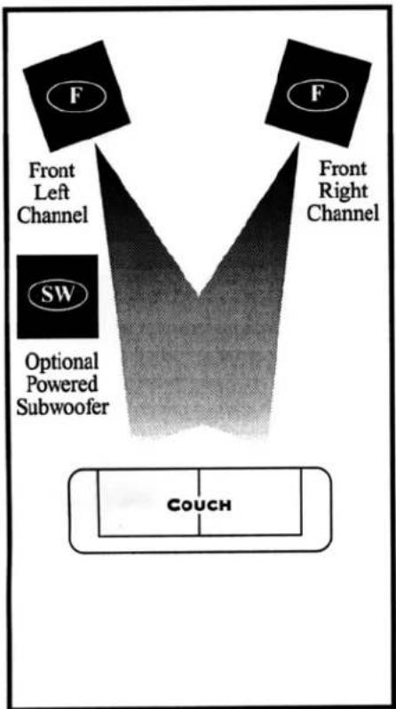
Your new Klipsch Powered Subwoofer has been designed specifically to enhance the performance of your Home Entertainment System, whether you are adding a subwoofer to an audio system or to a home theater system. For optimum performance, use Klipsch full range speaker systems as your
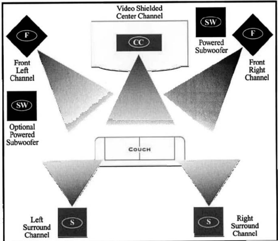
left and right front channels, and rear surround channels. Klipsch also engineers video shielded loudspeakers for use as center channels. The suggested placements below will help you plan your own Klipsch Home Theater System, or visit your authorized Klipsch dealer for more information.
Audio

Front Left and Right Channels

Left and Right Surround Channels

Center Channel

Powered Subwoofer
flowchart
graph TD
    A["Front Left Channel"] --> C["Couch"]
    B["Front Right Channel"] --> C["Couch"]
    D["SW"] --> E["Optional Powered Subwoofer"]
    F["F"] --> C["Couch"]
flowchart
graph TD
    A["Video Shielded Center Channel"] --> B["CC"]
    C["SW"] --> D["Powered Subwoofer"]
    E["F"] --> F["Front Left Channel"]
    E --> G["Optional Powered Subwoofer"]
    H["F"] --> I["Front Right Channel"]
    J["Couch"] --> K["Left Surround Channel"]
    J --> L["Right Surround Channel"]
Safety Warnings
DO NOT make connections (other than the power cord of the powered subwoofer) directly to any AC electrical wall outlet. Connection should be made only to an audio amplifier or equivalent component and only as described in the section entitled "Subwoofer Installation."
DO NOT operate the subwoofer under extremely humid or adverse temperature conditions.
Regardless of your amplifier's rated capacity, DO NOT operate the speakers at the full output (highest volume) position of the amplifier. Amplifiers can create extremely high levels of distortion when operated at full output and such distortion levels can cause damage to your loudspeakers.
Position speaker connection wires so that they do not create a hazard.
Subwoofer Placement
Your Klipsch subwoofer is designed to operate at frequencies below 120 Hz. As frequencies below 100 Hz are essentially non-directional, there may be several options for subwoofer placement. The positioning of your subwoofer will affect low frequency response, and moving the subwoofer slightly can make audible differences in performance. For maximum output, Klipsch & Associates recommends that the subwoofer be placed in or near a corner. Corner placement improves the loading of the subwoofer, increasing its efficiency. Increased efficiency also increases the maximum output of the entire system, improving the dynamic capability of the subwoofer. Variations in room acoustics may dictate placing the subwoofer in a location other than a corner, which may provide smoother low frequency response. Assymmetrical placement of two powered subwoofers in a home theater installation will improve low frequency reproduction by providing a smoother and more consistent response pattern. See diagram on page 1.
Some precautions should be observed when positioning the subwoofer:
- Provide at least a 4" clearance from any wall to allow proper ventilation for the subwoofer's power amplifier and clearance for the passive radiator located on the rear of the subwoofer.
- When recessing the subwoofer into a cabinet or wall, provide at least 4" of clearance around the perimeter of the subwoofer.
- Do not operate the subwoofer near a source of extreme heat.
- Do not operate the subwoofer outdoors or in humid environments.
- Because the standard subwoofer is not magnetically shielded, leave at least 12" of clearance around any television set.
Subwoofer Installation
Your subwoofer may be installed using either high level (speaker level) or line level inputs. The choice of input connection depends on the equipment you own.
High level (speaker level) inputs are the best choice when connecting the subwoofer to a receiver or INTEGRATED AMPLIFIER that lacks a subwoofer or PRE AMP output jack. See figure #1,2,5,6.
Line level inputs are the best choice when connecting the subwoofer to a separate PRE-AMP and power amp or any integrated amp or receiver equipment that has a PRE-AMP output. (Line level outputs include: a pre-amplifier out, subwoofer out or variable line out.) If only 1 pair of PRE-AMP outputs exist, a "Y" adapter may be used to split this output to your amplifier and subwoofer. If you are connecting your sub to a mono subwoofer output, best results are obtained if this jack does not have a low pass filter.
Either the L or R input on the subwoofer combines the left and right channel, resulting in a monaural signal which is passed on to the subwoofer. However there is a 6db increase in level if a y adapter is added to a mono line level input cable. This will connect the signal into both left and right inputs on the subwoofer. Best results are obtained if this jack does not have a low pass filter.
NOTE: Do not use both the low level and high level inputs simultaneously.
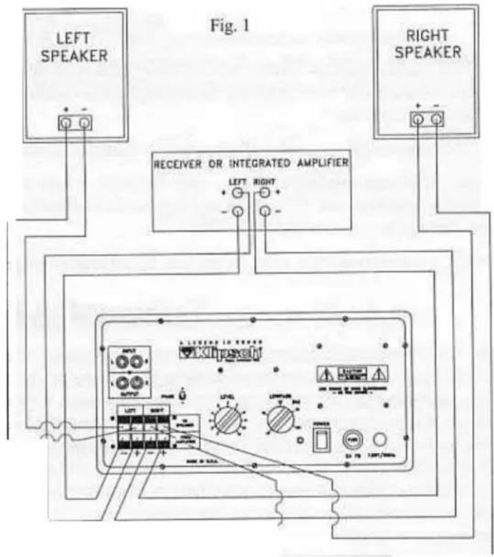
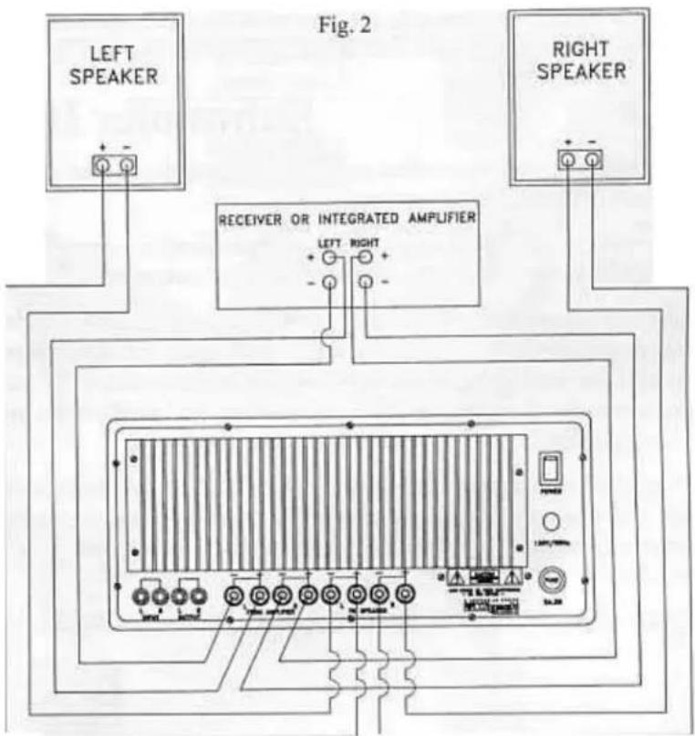
SWV, SW•8 and SW•10
connections for RECEIVER or INTEGRATED AMPLIFIER using high level (speaker level) inputs.
Use the following diagrams 1 & 2 to provide a limited range signal to the main speakers.
A 6db per octave high pass filter at 120 Hz will remove deep bass frequencies from your main speakers. This is the preferred method when using smaller bookshelf loud speakers that are more easily stressed by loud low frequencies. Set the low pass control at or slightly below 120 Hz as an initial setting (except SW V).
Important! Refer to line 5 under trouble shooting on pg 9.
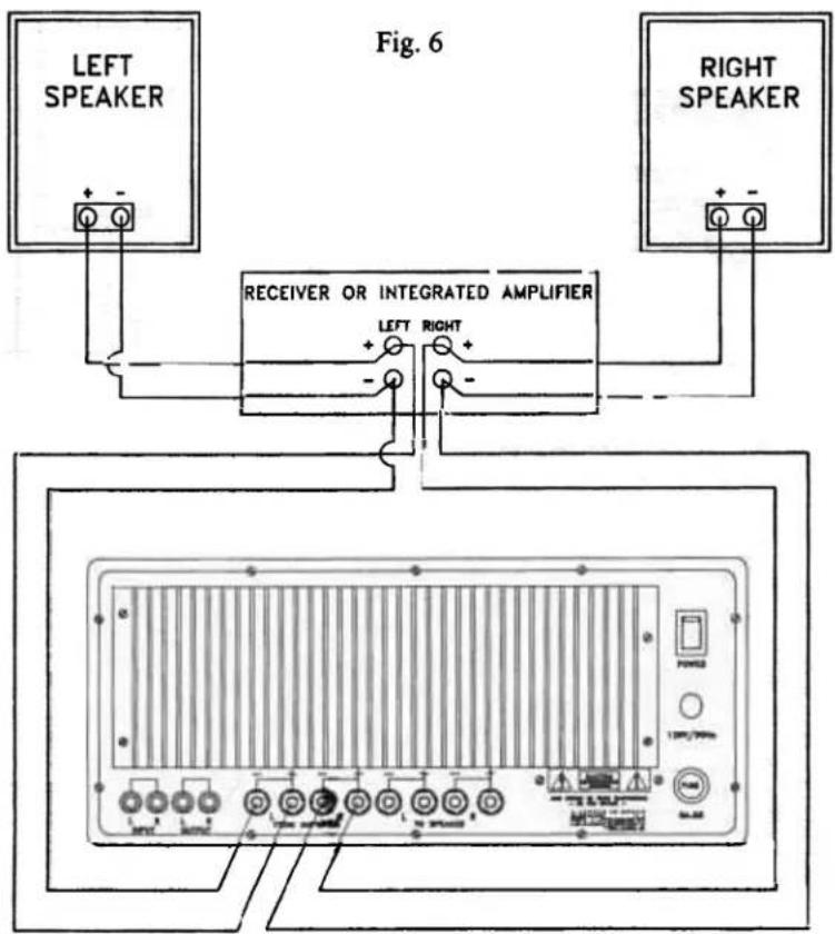
SW•12 and SW•15
connections for RECEIVER or INTEGRATED AMPLIFIER using high level (speaker level) inputs
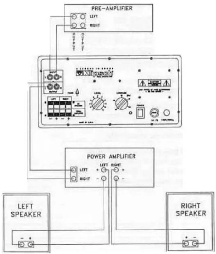
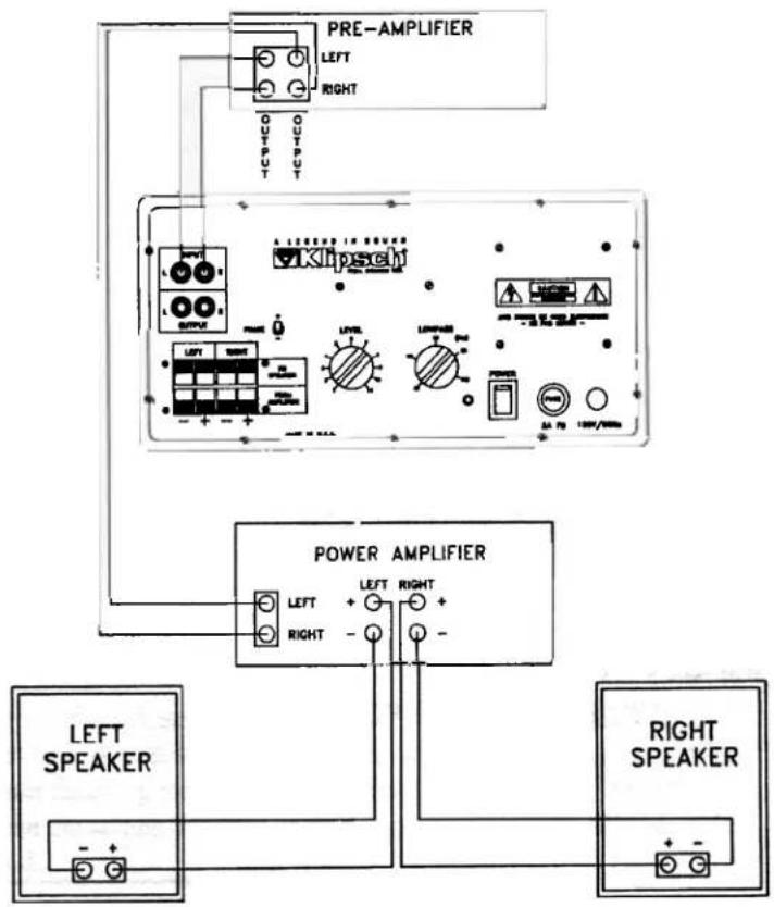
SW•8 and SW•10
connections for separate PRE-AMPLIFIER and POWER AMP using line level inputs
Use the following diagrams 3&4 to provide a limited range signal to the main speakers using line level connections. A 6DB per octave at 80 Hz will remove deep bass frequencies from your main speakers. This is the preferred method of connection when using smaller bookshelf loud speakers that are more easily stressed by loud low frequencies. These diagrams also apply to integrated amplifiers and receivers that are equipped with pre amp output and power amp input jacks. Set the low pass control at or below 80Hz as an initial setting. Use only shielded cable to connect all RCA plugs.
flowchart
graph TD
    A["PRE-AMPLIFIER"] --> B["POWER AMPLIFIER"]
    B --> C["LEFT SPEAKER"]
    B --> D["RIGHT SPEAKER"]
    style A fill:#f9f,stroke:#333
    style B fill:#ccf,stroke:#333
    style C fill:#cfc,stroke:#333
    style D fill:#fcc,stroke:#333
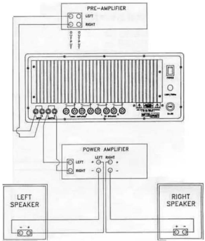
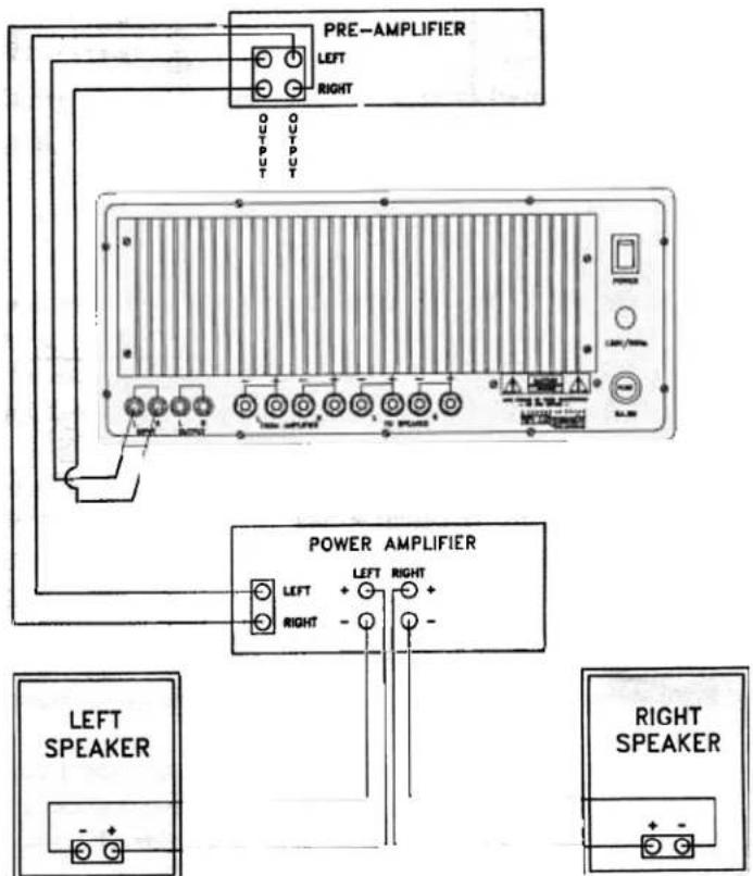
SW•12 and SW•15
connections for PRE-AMPLIFIER using line level inputs
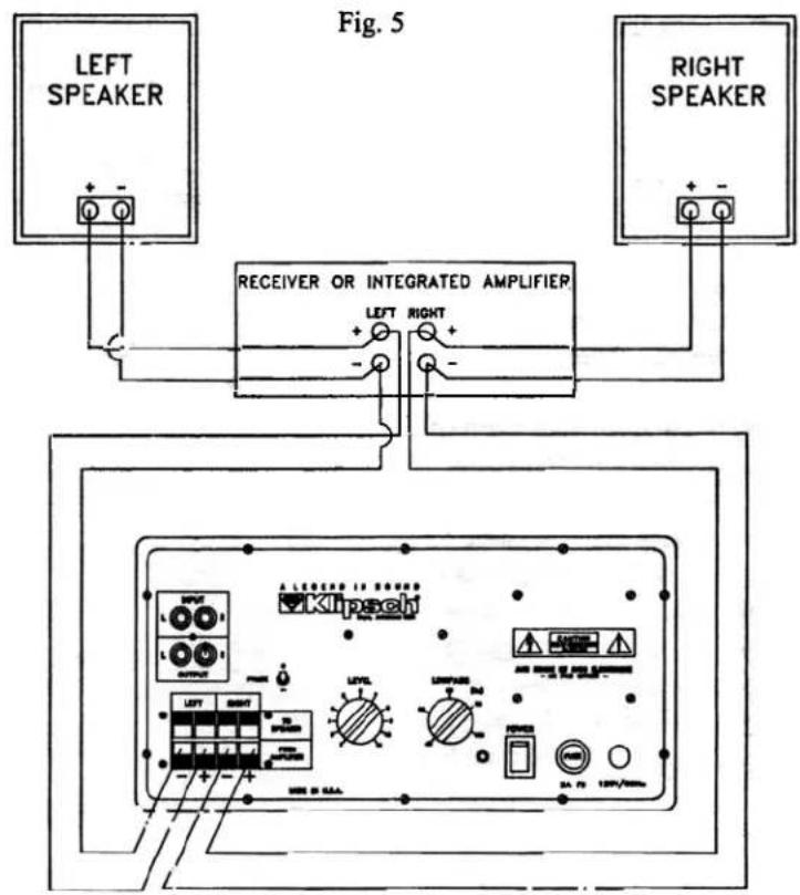
connections for RECEIVER or INTEGRATED AMPLIFIER using high level (speaker level) inputs.
Use the following diagrams to provide a full range signal to the main speakers.
If your receiver has a second set of speaker terminals (speaker B) the subwoofer can be hooked to these and your front panel speaker switches set accordingly.
Set the low pass control at or below the low frequency limit of your main speakers as an initial setting. Refer to their specification sheet for guidance.
SW•12 and SW•15
connections for RECEIVER or INTEGRATED AMPLIFIER using high level (speaker level) inputs
SW•8 and SW•10
connections for PRE-AMPLIFIER using line level inputs
Use the following diagrams to provide a full range signal to the main speakers.
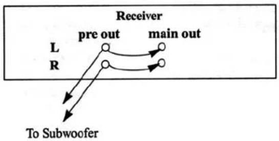
When using a separate pre amp and power amp, or receiver with pre amp output jacks. If you are using a receiver that has pre amp outputs connected to power amp inputs with external jumpers, a pair of "Y" adapters to split the pre amp input will be needed. See figure #8 Set the low pass control at or below the low frequency limit of your main speakers as an initial setting. Refer to their specifications for guidance.
Use only shielded cable to connect all RCA phone plugs.
connections for PRE-AMPLIFIER using line level inputs
Fig. 8
flowchart
graph TD
    A["Receiver"] --> B["pre out"]
    A --> C["main out"]
    D["L"] --> E["To Subwoofer"]
    F["R"] --> E
    E --> G["Output"]
    style A fill:#f9f,stroke:#333
    style D fill:#ccf,stroke:#333
    style F fill:#ccf,stroke:#333
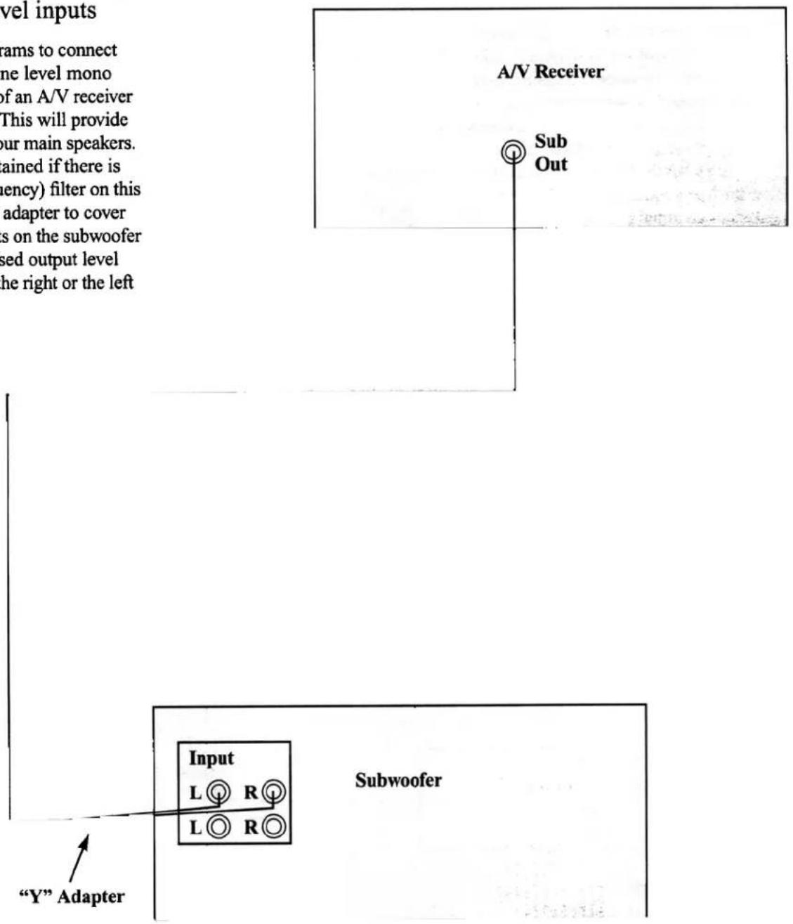
SWV, SW•8, SW•10, SW•12 and SW•15
Fig. 10
connections for A/V RECEIVER or SURROUND PROCESSOR using line level inputs
Use the following diagrams to connect your subwoofer to a line level mono subwoofer output jack of an A/V receiver or surround processor. This will provide a full range signal to your main speakers. Best results will be obtained if there is no low pass (high frequency) filter on this jack. The use of a "Y" adapter to cover both left and right inputs on the subwoofer will result in an increased output level relative to using either the right or the left input alone.
Operating Controls
Power Switch
Located on the rear of the subwoofer, the Power Switch turns the subwoofer "on" and "off".
The subwoofer should be unplugged and in the "off" position during the installation procedure.
Level Control
Located on the rear panel of the SW V, SW• 8 and the SW•10, and on the front panel (under the grill) of the SW•12 and SW•15, the Level Control adjusts the volume of the subwoofer relative to your other speakers.
Low Pass Control
Located on the rear panel of the SW•8 and SW•10 and on the front panel of the SW•12 and SW•15, the variable low pass filter controls the upper frequency limit of the subwoofer. The filter is continuously variable from 40 to 120 Hz, and is used to obtain a proper match between the subwoofer and the main speakers.
It should generally be set at or near the high pass frequency being used with your left and right speakers. If this is being provided by your Klipsch subwoofer, it will be 120 Hz (speaker level) or 80 Hz (line level). If you are providing your own high pass by way of an electronic crossover, match that frequency. In some cases, you may elect to utilize no high pass to the left and right. In these situations the low pass control should be set at or slightly below (if possible) the low frequency limit of your main speakers. In all cases, experimentation is recommended due to variability in placement, room acoustics and associated equipment.
Phase Switch (SW•8 and SW•10 only)
Located on the rear panel, the Phase Switch is used to switch the polarity (phase) of the subwoofer relative to your main speakers to obtain maximum output of your total system. The Phase Switch should be set to the “positive” setting to begin the set-up procedure. Listen to a recording with a prominent bass line in your listening chair. Then set the switch to the opposite setting and again audition the same recording, in your listening chair. Use the setting that gives you the greatest quantity of bass. If the subwoofer is repositioned, this procedure may have to be repeated.
Phase Control (SW•12 and SW•15 only)
Located on the front panel, the Phase Control is continuously variable between 0 and 180 degrees. It is used to maximize the output of your total system and provide a better resolution than a simple 0 or 180 degree switch. It should be set to the "0" setting to begin the set-up procedure as described above. After set-up, experiment with the setting to obtain best performance.
Troubleshooting
Little or no output from the subwoofer will result if the polarity of the speaker level connections between your amplifier and the subwoofer are not proper. See figures 5 & 6.
If your subwoofer has no output:
- Double check your power and system connections.
- Make sure the level control is turned up.
- Check the green LED located on the back panel of the SW•8 and the SW•10, or the front (under the grill) of the SW•12 and SW•15. If the LED is not lit, unplug the subwoofer and change the AC fuse.
- The SW • 8 and SW •10 are protected by a poly switch. If run for extended periods beyond their designed power rating, the poly switch will engage and shut down the system. If this occurs, turn off the Power Switch, reduce the volume and wait five minutes before re-starting the system.
- If you experience a noticeable hum when the sub is connected to your system try installing a 3 to 2 AC prong adapter on the subwoofer's power cord. If the hum persists and your audio system is connected to your video equipment which is in turn connected to a cable television line, disconnect the cable line from video equipment. If the hum disappears, consult your dealer for a ground isolator for your cable line. Hooking up your subwoofer with the speaker level inputs may reduce hum also.
- If your Klipsch subwoofer is connected to your system via the line level inputs and you experience interference from a nearby radio station, switch to the high level inputs on your subwoofer. The high level inputs utilize a differential style input circuit which will reduce or eliminate this interference.
- If you connect the subwoofer to a second set of speaker terminals (ie. Speaker B) as described on page 6, and there is a drastic loss of volume from your main speakers, this means that the two sets of speaker terminals on your receiver are wired in series. Another type of hookup should be attempted, such as hooking the subwoofer to the same terminals as your main speakers (Fig.'s 5 & 6) or connecting as per Fig.'s 1 & 2.
Specifications
SWV
Type: 8" Bass-Reflex Enclosure
Amplifier: 50 Watts continuous into 8 ohms
Dynamic Headroom: 2 dB (80 Watts into 8 ohms)
Frequency Response: 32 - 85 Hz ± 3 dB
Low Pass Crossover:
Fixed at 85 Hz,
24 dB/Octave slope above 120 Hz.
High Pass Crossover (main speakers):
Speaker level outputs with fixed
High Pass at 120 Hz, 6 dB/Octave slope.
Phase: Fixed
Inputs/Outputs: High level speaker terminals only.
Drive Component: K - 1012 - K 8" (20.3 cm) driver
Dimensions: 18.75" H x 13.25" W x 13.5" D (with feet and grill)
47.7 cm H x 33.7 cm W x 34.3 cm D
Weight: 32 lbs. - 14.5kg
Cabinet: Fiber board construction.
Finishes: Ebony vinyl finish only.
Voltage: 110/120 VAC/60 Hz
SW•8 Subwoofer
Type: 8" Bass-Reflex Enclosure with 10" Passive Radiator
Amplifier: 65 Watts continuous into 8 ohms
Dynamic Headroom: 2 dB (100 Watts into 8 ohms)
Frequency Response: 32 - 120 Hz ± 3 dB
Low Pass Crossover:
Continuously variable from 40 - 120 Hz, 24 dB/Octave slope above 120 Hz
High Pass Crossover (main speakers):
Line level outputs with fixed High Pass at 80 Hz, 6 dB/Octave slope. Speaker level outputs with
fixed High Pass at 120 Hz, 6 dB/Octave slope.
Phase: Switchable 0 - 180 degrees
Inputs/Outputs: Line Level RCA phono jacks. High level speaker terminals.
Drive Component:
K - 1012 - K 8" (20.3 cm) driver
KD - 103 - K 10" (25.4 cm) passive radiator.
Dimensions: 18.79" H x 13.25" W x 14.02" D (with feet and grill)
47.7 cm H x 33.7 cm W x 35.6 cm D
Weight: 36 lbs. - 16.3 kg
Cabinet: Fiber board construction available in oak, or walnut veneer.
Finishes: Whitewash, Light Oak, Medium Oak, Walnut, Black Satin, Unfinished
Voltage: 110/120 VAC/60 Hz
SW·10 Subwoofer
Type: 10" Bass-Reflex Enclosure with
12" Passive Radiator
Amplifier: 100 Watts continuous into 8 ohms
Dynamic Headroom: 2 dB (150 Watts into 8 ohms)
Frequency Response: 30 - 120 Hz ± 3 dB
Low Pass Crossover:
Continuously variable from 40 -120 Hz, 24 dB/Octave slope above 120 Hz
High Pass Crossover (main speakers):
Line level outputs with fixed High Pass at 80 Hz, 6 dB/Octave slope. Speaker level outputs with
fixed High Pass at 120 Hz, 6 dB/Octave slope.
Phase: Switchable 0 - 180 degrees
Inputs/Outputs: Line Level RCA phono jacks. High level speaker terminals.
Drive Component:
K - 1013 - K 10" (25.4 cm) driver
KD - 122 - K 12" (30.5 cm) passive radiator.
Dimensions: 21.25" H x 14" W x 15.09" D
(with feet and grill)
54 cm H x 35.6 cm W x 38.3 cm D
Weight: 43 lbs. - 19.5 kg
Cabinet: Fiber board construction available in oak, or walnut veneer.
Finishes: Whitewash, Light Oak, Medium Oak, Walnut, Black Satin, Unfinished
Voltage: 110/120 VAC/60 Hz
SW•12 Subwoofer
ype: 12" Bass-Reflex Enclosure with 12" Passive Radiator
Amplifier: 150 Watts continuous into 8 ohms
Dynamic Headroom: 1 dB (189 Watts into 8 ohms)
Frequency Response: 28 - 120 Hz ± 3 dB
Low Pass Crossover:
Continuously variable from 40 - 120 Hz, 24 dB/Octave slope above 120 Hz
High Pass Crossover (main speakers):
Line level outputs with fixed High Pass at 80 Hz, 6 dB/Octave slope. Speaker level outputs with fixed High Pass at 120 Hz, 6 dB/Octave slope.
Phase: Continuously variable 0 - 180 degrees
Inputs/Outputs: Line Level RCA phono jacks.
High level speaker terminals.
Drive Component: K - 26 - K 12" (30.5 cm) driver.
KD - 122 - K 12" (30.5 cm) passive radiator
Dimensions: 23.5" H x 15.625" W x 16.49" D
(with feet and grill)
59.7 cm H x 39.7 cm W x 41.9 cm D
Weight: 60 lbs.-27.2 kg
Cabinet: Fiber board construction available in oak, cherry or walnut veneer.
Finishes: Whitewash, Light Oak, Medium Oak, Walnut, Black Satin, Cherry, Unfinished
Voltage: 110/120 VAC/60 Hz
Subwoofer SW·15
Type: 15 Bass-Reflex Enclosure with 15" Passive Radiator.
Amplifier: 200 Watts RMS into 8 ohms.
Dynamic Headroom: 1dB (252 Watts into 8 ohms).
Frequency Response: 27 - 120 Hz ± 3 dB.
Low Pass Crossover:
Continuously variable from 40 - 120 Hz, 24 dB/Octave slope above 120 Hz.
High Pass Crossover (main speakers):
Line level outputs with fixed High Pass at 80 Hz, 6 dB/Octave slope. Speaker level outputs with fixed High Pass at 120 Hz, 6 dB/Octave slope.
Phase: Continuously variable 0 - 180 degrees.
Inputs/Outputs: Line Level RCA phono jacks.
High level speaker terminals.
Drive Components: K - 35 - K 15" (38.1 cm) driver.
KD - 18 - K 15" (38.1 cm) passive radiator.
Dimensions: 26" H x 18.5" W x 19.56" D
(w/o feet)
66 cm H x 47 cm W x 49.7 cm D
Weight: 82 lbs. 37.1 kg
Cabinet: Fiberboard construction available in oak, cherry or walnut veneer.
Finishes: Whitewash, Light Oak, Medium Oak, Walnut, Black Satin, Unfinished
Voltage: 110/120 VAC/60 Hz
ATTENTION
It is normal to experience some port turbulence (a noise that resembles wind traveling in and out of the speaker) in the Klipsch SWV powered subwoofer when it is played at high volume levels
If you detect a noticeable hum in the SW8, SW10, SW12 or SW15 model, please refer to the “Troubleshooting” section of your owners manual.
- Series II POWERED SUBWOOFERS
- Planning Your Klipsch Home Entertainment System
- Audio
- Safety Warnings
- Subwoofer Placement
- Some precautions should be observed when positioning the subwoofer:
- Subwoofer Installation
- SWV, SW•8 and SW•10
- SW•12 and SW•15
- SW•8 and SW•10
- SWV, SW•8, SW•10, SW•12 and SW•15
- connections for A/V RECEIVER or SURROUND PROCESSOR using line level inputs
- Operating Controls
- Power Switch
- Level Control
- Low Pass Control
- Phase Switch (SW•8 and SW•10 only)
- Phase Control (SW•12 and SW•15 only)
- Troubleshooting
- Specifications
- SWV
- SW•8 Subwoofer
- SW·10 Subwoofer
- SW•12 Subwoofer
- Subwoofer SW·15
- ATTENTION
Brand : KLIPSCH
Model : SWV
Category : Subwoofer