HG50NE478SF - Television SAMSUNG - Free user manual and instructions
Find the device manual for free HG50NE478SF SAMSUNG in PDF.

User questions about HG50NE478SF SAMSUNG
0 question about this device. Answer the ones you know or ask your own.
Ask a new question about this device
Download the instructions for your Television in PDF format for free! Find your manual HG50NE478SF - SAMSUNG and take your electronic device back in hand. On this page are published all the documents necessary for the use of your device. HG50NE478SF by SAMSUNG.
USER MANUAL HG50NE478SF SAMSUNG
Thank you for purchasing this Samsung
product. To receive more complete service, please register your product at
www.samsung.com/register
Model
Serial No.
Figures and illustrations in this User Manual are provided for reference only and may differ from actual product appearance. Product design and specifications may be changed without notice.
Introduction
This TV B2B (Business to Business) model is designed for hotels or the other hospitality businesses, supports a variety of special functions, and lets you limit some user (guest) controls.
Operational Modes
This TV has two modes: Interactive and Stand-alone mode.
- Interactive mode: In this mode, the TV communicates with and is fully or partially controlled by a connected Set Back Box (SBB) or Set Top Box (STB) provided by a hospitality SI (System Integration) vendor. When the TV is initially plugged in, it sends a command that attempts to identify the SSB or STB connected to it. If the TV identifies the SBB or STB and the SBB or STB identifies the TV, the TV gives full control to the SBB or STB.
- Stand-alone mode: In this mode, this TV works alone without an external SBB or the STB.
The TV has a Hotel (Hospitality) Menu that lets you easily set its various hospitality functions. Please see pages 27 to 32.
The Menu also lets you activate or de-activate some TV and hospitality functions so you can create your optimal hospitality configuration.
Still image warning
Avoid displaying still images (such as jpeg picture files) or still image elements (such as TV channel logos, panorama or 4:3 format images, stock or news bars etc) on the screen. Displaying still pictures continually can cause uneven screen wear, which will affect image quality. To reduce the chance that this effect will occur, please follow the recommendations below:
- Avoid displaying the same TV channel for long periods.
• Always try to display a full screen image. - Reduce brightness and contrast to help prevent the occurrence of after-images.
- Frequently use all TV features designed to reduce image retention and screen burn-in. Refer to the proper user manual section for details.
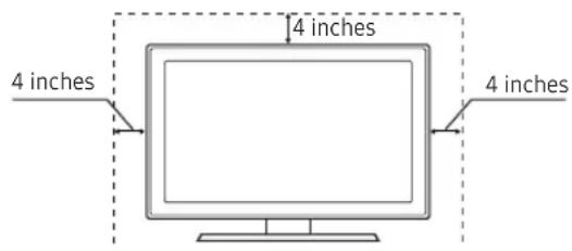
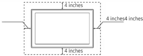
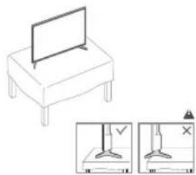
Ensuring Proper Ventilation
When you install the TV, maintain a distances of at least 4 inches between the TV and other object (walls, cabinet sides, etc.) to ensure proper ventilation.
Failing to maintain proper ventilation may result in a fire or problems with the product caused by an increase in its internal temperature.
When using a stand or wall-mount, use parts provided by Samsung Electronics only.
Using parts provided by another manufacturer may cause difficulties with the product or result in injury caused by the product falling.
Installation with a stand. Installation with a wall-mount.
Additional Information
The appearance of the TV and its accessories may differ from the illustrations in this manual, depending on the TV.
Be careful when you touch the TV. Some parts can be hot.
Contents
- Accessories......4
• Installing the LED TV Stand 5 - Assembling the swivel stand (Depending on models) 10
• Using the TV's Controller.... 12 - The Connection Panel.... 13
• Using the TV's remote Controller.... 19 - Connecting the TV to the Lodgenet game controller or a STB of a SI vendor.... 21
- Connecting the Audio Output to an Audio Amplifier 23
- Connecting the MediaHub HD 24
- Connecting the RJP (Remote Jack Pack) 25
- Setting the Hotel Option Data.... 27
- Installing the Wall Mount.... 50
• Securing the TV to the Wall 51 - Anti-theft Kensington Lock.... 52
- Specifications.... 53
- Dimensions....58
Accessories
Please make sure the following items are included with your LED TV. If any items are missing, contact your dealer.
The items' color and shape may vary, depending on the model.
The parts for the stand are listed under Stand Components on the following page.
List of Parts
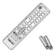

Remote Control & Batteries (AAA x 2) Power Cord
Safety Guide / Quick Setup Guide (Not available in all locations)

Data Cable (depending on the model) (BN39-00865B, BN39-01011E)
Hotel Mount Kit (depending on the model)

Holder-Wire stand (1EA) (depending on the model)
Assembling the Holder Wire Stand

Ferrite Core (depending on the model)
Wall Mount Adapter (Depending on the model)
Installing the LED TV Stand
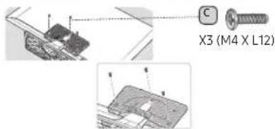
Components
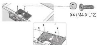
When installing the stand, use the provided components and parts.
HG32NE460S
A
B
C
X 8 (M4 X L12)
Stand Guide Stand Screws
1
3
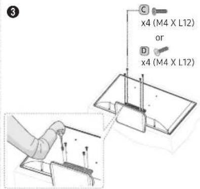
Tight the bottom of the screw first, and stow the upper side of screw last.
Progress the assembly of screw in the manual's order.
2
natural_image
Isometric illustration of a table with a tray and a small object, no text or symbols present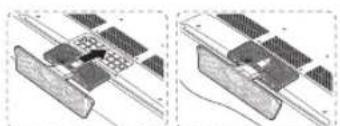
natural_image
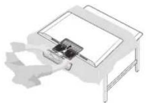
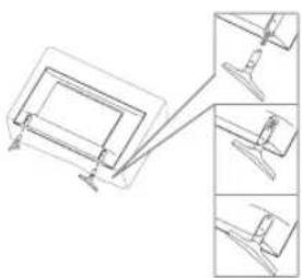
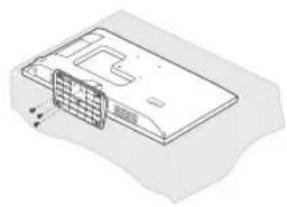
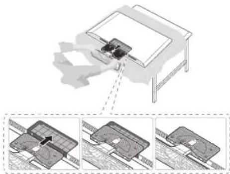
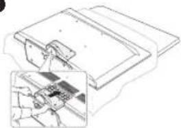
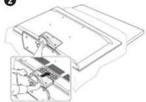
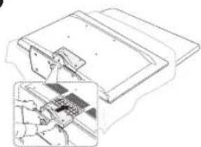
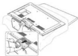
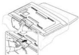
Two technical diagrams showing a mechanical assembly with no visible text, numbers, or symbols.Place a soft cloth over the table to protect the TV, and then place the TV on the cloth screen-side down.
Insert the Stand Guide into the slot on the bottom of the TV.
Slide and assemble it to the end line in the direction of arrow.
◆ HG40NE460S/HG43NE460S/HG50NE460S
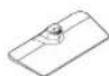
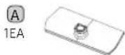
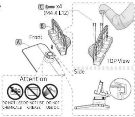
A
1EA
(1L,1R)


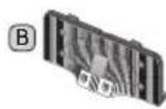
B
2EA


C

x4(M4 X L12)
Stand Guide Stand Screws
1
natural_image
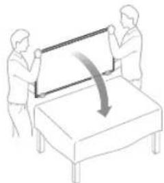
Illustration of two people installing or adjusting a large panel on a bed, with a curved arrow indicating rotation (no text or symbols)2
natural_image
Technical line drawing of a mechanical clamp or bracket assembly (no text or symbols)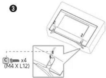
4
natural_image
Technical line drawing of a mechanical assembly with two views (top and side), no text or symbols present.5
natural_image
Line drawing of two people handling a large screen on a table (no text or symbols)6
natural_image
Line drawing of a flat-screen TV on a table with two side-view diagrams showing different viewing angles (no text or symbols)HG24NE470A

1 EA


x3 (M4 x L12, for 24" models)
Stand Screws
1
2
natural_image
Diagram showing two electronic components with an arrow indicating transformation (no text or symbols present)3
natural_image
Isometric line drawing of a computer monitor case with a grid and ventilation slots (no text or symbols)Place a soft cloth over the table to protect the TV, and then place the TV on the cloth screen-side down.
Insert the Stand Guide into the slot on the bottom of the TV.
HG28NE470
A


X7(M4XL12)
Stand Guide Stand Screws
3
Tight the bottom of the screw first, and stow the upper side of screw last.
Progress the assembly of screw in the manual's order.
2
natural_image
Diagram showing a mechanical assembly with three views of a table and a close-up of internal components (no text or symbols)Place a soft cloth over the table to protect the TV, and then place the TV on the cloth screen-side down.
Insert the Stand Guide into the slot on the bottom of the TV.
Slide and assemble it to the end line in the direction of arrow.
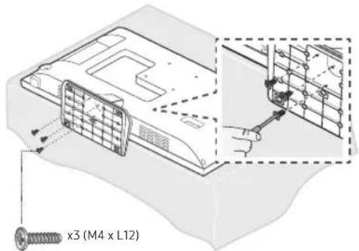
HG32NE470S/HG40NE470S/HG43NE470S/HG50NE470S/HG55NE470/HG32NE477S/HG40NE477S/HG43NE477S/HG50NE477S/HG55NE477
B 1FA


x8(M4 X L12)


x4(M4 X L12)
Stand Guide Stand Screws Security Screws
1
2
natural_image
Technical line drawing of a mechanical assembly with an inset close-up showing internal components (no text or symbols)Place a soft cloth over the table to protect the TV, and then place the TV on the cloth screen-side down.
Insert the Stand Guide into the slot on the bottom of the TV.
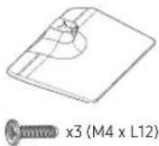
HG22NE478

1 EA


(M4 x L12)
Stand Screws
1
natural_image
Technical line drawing of a mechanical component with internal parts and a zoomed-in detail view (no text or symbols)2
HG32NE478B
B 1 EA


x7 (M4 X L12)


× 3 (M4 X L12)
Stand Guide Stand Screws Security Screws
1
2
natural_image
Technical line drawing of a mechanical assembly with an inset showing a close-up view of internal components (no text or symbols)Place a soft cloth over the table to protect the TV, and then place the TV on the cloth screen-side down.
Insert the Stand Guide into the slot on the bottom of the TV.
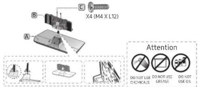
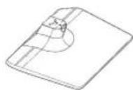
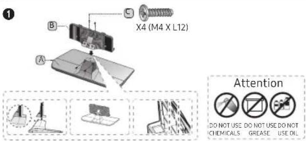
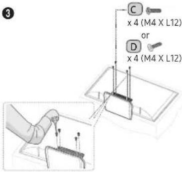
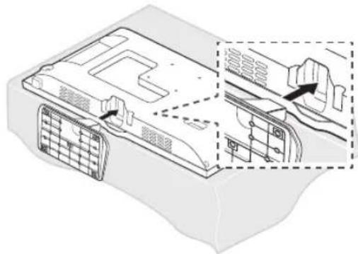
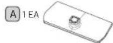
◆ HG40NE478S/HG43NE478S/HG50NE478S/HG55NE478S
A 1 EA
B 1EA


x8 (M4 X L12)


x4 (M4 X L12)
Stand Guide Stand Screws Security Screws
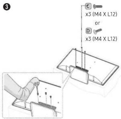
1
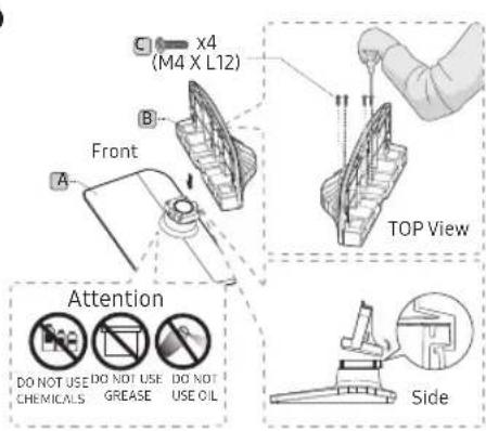
2
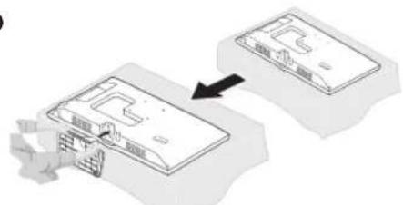
natural_image
Technical line drawing of a mechanical assembly with an inset showing a close-up of a component detail (no text or symbols)Place a soft cloth over the table to protect the TV, and then place the TV on the cloth screen-side down.
Insert the Stand Guide into the slot on the bottom of the TV.
◆ HG60NE470/HG60NE477
A
B
1 EA

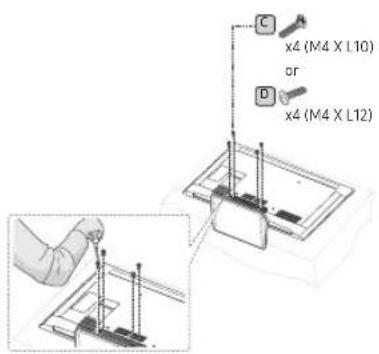
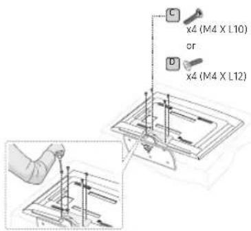
C

x4 (M4 X L10)
x4 (M4 X L12)
D

x4 (M4 X L12)
Stand Guide Stand Screws Security Screws
1
natural_image
Technical line drawing of a mechanical assembly with an inset showing internal components (no text or symbols)Place a soft cloth over the table to protect the TV, and then place the TV on the cloth screen-side down. Insert the Stand Guide into the slot on the bottom of the TV.
HG65NE478
A
B
1 EA

C

x4 (M4 X L10)
x4 (M4 X L12)
D

x4 (M4 X L12)
Stand (differs, depending on the model)
Guide Stand Screws Security Screws
1
2
natural_image
Technical line drawing of a mechanical assembly with internal components and a close-up inset (no text or symbols)Place a soft cloth over the table to protect the TV, and then place the TV on the cloth screen-side down. Insert the Stand Guide into the slot on the bottom of the TV.

NOTE
- Make sure to distinguish between the front and back of the Stand and Stand Guide when connecting them.
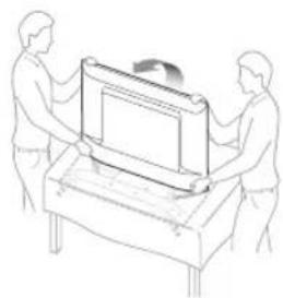
- Make sure that at least two persons lift and move the TV.
- The number of screws may differ depending on the model.
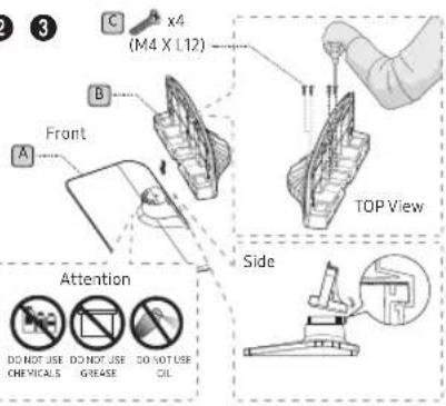
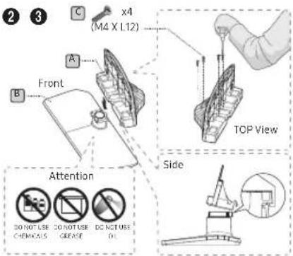
Assembling the swivel stand (Depending on models)
You can configure these stands so that the TVs swivel 20 degrees left and right, 60 degrees left and right, or 90 degrees left and right using the BRACKET HOLDER SWIVEL.
20° swivel
To configure the TV so that it swivels 20° left and right, insert the prong on the bottom of the stand through the curved hole in the Bracket Holder Swivel marked 20°. Then, fix the Bracket Holder Swivel to the stand using the three supplied screws as shown below.
natural_image
Technical diagram showing mechanical components with mounting holes and a close-up view of the assembly (no text or symbols present)60^ swivel
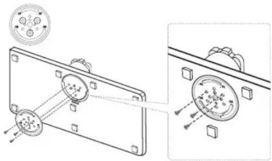
To configure the TV so that it swivels 60° left and right, insert the prong on the bottom of the stand through the curved hole in the Bracket Holder Swivel marked 60°. Then, fix the Bracket Holder Swivel to the stand using the three supplied screws as shown below.
natural_image
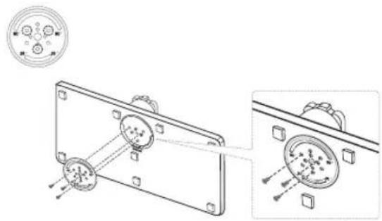
Technical line drawing of a mechanical component with mounting holes and internal circular features (no text or symbols)90° swivel
To configure the TV so that it swivels 90° left and right, remove the Bracket Holder Swivel, and then screw the three supplied screws into the stand as shown below.
natural_image
Technical line drawing showing two views of a mechanical component with mounting holes and a circular feature, no text or symbols present.
natural_image
Two technical illustrations of a mechanical component with hinged ends, shown in two different orientations (no text or symbols)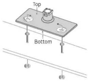
Affix the stand to a flat surface such as a dresser top, desk top, or entertainment center as shown.

WARNING: To prevent injury, you must attach this TV securely to the floor, a table, a dresser top, etc. with the Hotel Mount Kit as described in these instructions.
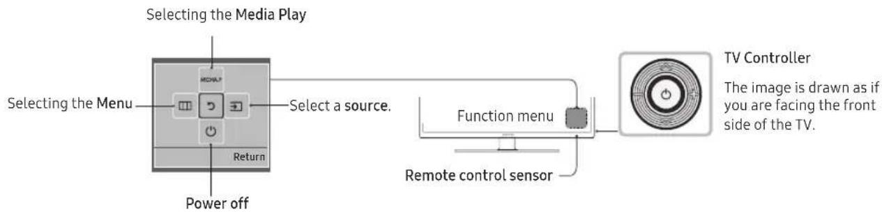
Using the TV's Controller
22/32/24/28/55/60/65NE47\*
The TV's Controller, a small joy stick like button on the rear right side of the TV, lets you control the TV without the remote control.
The product color and shape may vary depending on the model.
To exit the menu, press the Controller for more than 1 second.
When selecting a function by moving the controller up/down/left/right, be sure not to press up on the controller. If you press up first, it will not operate correctly.
32/40/43/50NE47\*
The TV's Controller on the bottom right side of the TV, lets you control the TV without the remote control.
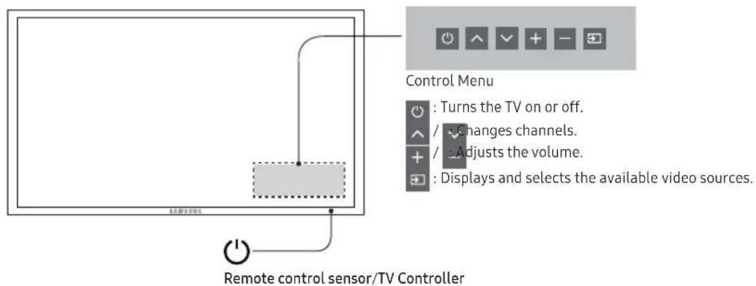
If you press it first, the control menu appears. You can select the function by pressing and holding the TV's controller.
The product color and shape may vary depending on the model.
With the TV's Controller, you cannot perform other operations except for turning the TV on or off, changing the channel, adjusting the volume, and switching the input source.
Standby mode
Your TV enters Standby mode when you turn it off, and continues to consume a small amount of electric power. To be safe and to decrease power consumption, do not leave your TV in standby mode for long periods of time (when you are away on vacation, for example). It is best to unplug the power cord.
The Connection Panel
HG32NE460S
HG40NE460S/HG43NE460S/HG50NE460S
HG32NE473
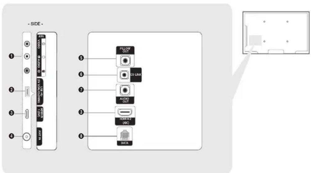
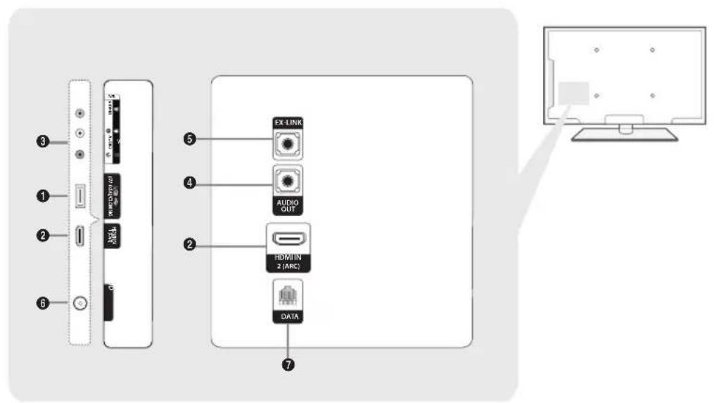
HG24NE470/HG28NE470/HG40NE470S/HG43NE470S/HG50NE470S/HG55NE470/HG60NE470S/HG40NE477S/HG43NE477S/HG50NE477S/HG55NE477/HG60NE477S
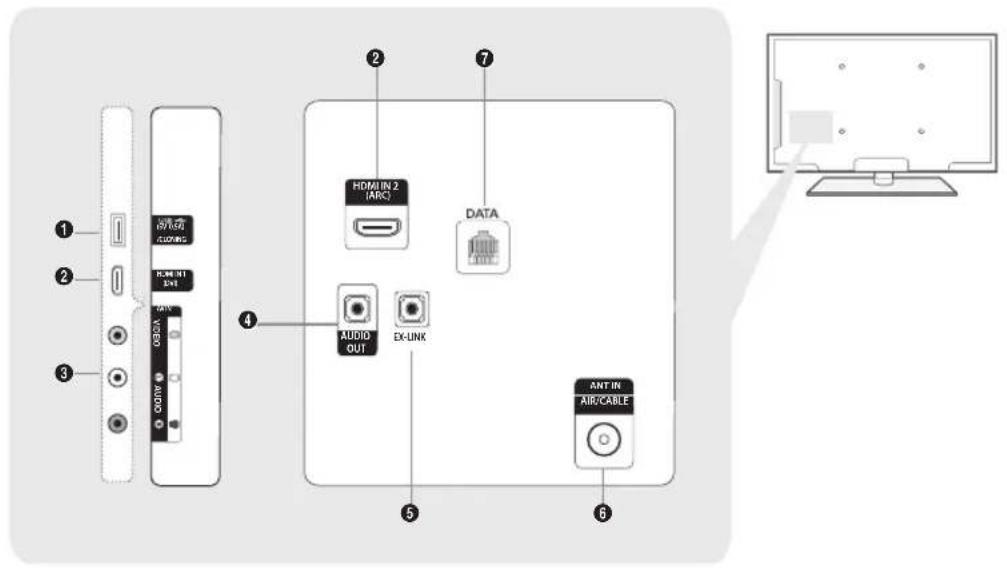
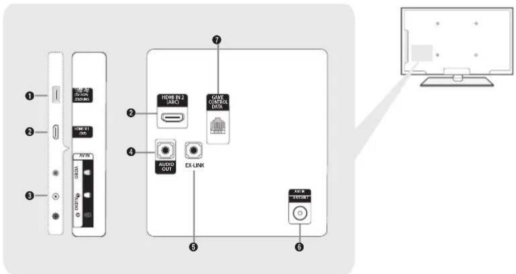
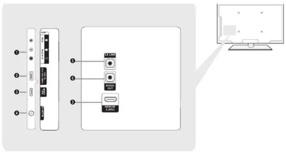
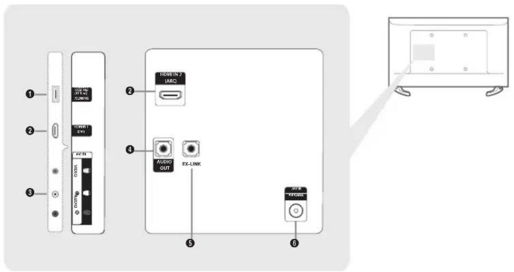
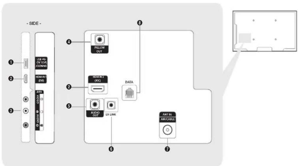
Connect an external device to your TV, make sure that the TV and the device are turned off.
When connecting an external device, match the color of the connection terminal to the cable.
① HDMI IN
-Connects to the HDMI jack of a device with an HDMI output.
No separate sound connection is needed for an HDMI to HDMI connection. HDMI connections carry both audio and video.
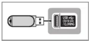
② USB / CLONING
- Connector for software upgrades and Media Play, etc.
-Service connection.
③ VIDEO / L-AUDIO-R
- Connect a VIDEO cable to an appropriate external A/V device such a VCR, DVD, or Camcorder.
- Connect audio cables to "L-AUDIO-R" on your TV and the other ends to corresponding audio out jacks on the A/V device.
4 EX-LINK
- Connect this jack to the jack on the optional RJP (Remote Jack Pack). The RJP allows you to connect external devices (Camcoders, PCs, DVD players, etc) easily.
5 AUDIO OUT
-Connects to the audio input jacks on an Amplifier/Home Theater.
6 ANT IN or AIR/CABLE
- To view television channels correctly, the TV must receive a signal from one of the following sources:
- An outdoor antenna / A cable television system / A satellite receiver
⑦ DATA
– Used to support data communication between the TV and the external SBB or STB.
-Connects using RJ-12 TV type plugs.
8 GAME CONTROL DATA
- Used to connect the Lodgenet game controller in the Lodgenet system or support data communication between the TV and the external SBB or STB.
-Connects using an RJ-12 type of plug.
Display Modes
You can also select one of the standard resolutions listed in the Resolution column. The TV will automatically adjust to the resolution you choose.
After connecting a computer to the TV, set the screen resolution for the TV on the computer. The optimal resolution is 1920 x 1080 @ 60 Hz. If it is set to any other than in the table below, the TV may display nothing. Set the resolution properly, referring to the user guide of the computer or its graphic card.
The resolutions in the table are recommended.
Optimal resolution is 1366 X 768 @ 60 Hz.
| Display Mode Display Format | Horizontal Frequency (kHz) | Vertical Frequency (Hz) | Pixel Clock (MHz) | Sync Polarity (H / V) | ||
| IBM | 720 x 400 | 70Hz | 31.469 | 70.087 | 28.322 | -/+ |
| MAC | 640 x 480 | 67Hz | 35.000 | 66.667 | 30.240 | -/- |
| 832 x 624 | 75Hz | 49.726 | 74.551 | 57.284 | -/- | |
| VESA DMT | 640 x 480 | 60Hz | 31.469 | 59.940 | 25.175 | -/- |
| 640 x 480 | 72Hz | 37.861 | 72.809 | 31.500 | -/- | |
| 640 x 480 75Hz | 37.500 | 75.000 31.500 -/- | ||||
| 800 x 600 | 60Hz | 37.879 | 60.317 | 40.000 | +/+ | |
| 800 x 600 | 72Hz | 48.077 | 72.188 | 50.000 | +/+ | |
| 800 x 600 | 75Hz | 46.875 | 75.000 | 49.500 | +/+ | |
| 1024 x 768 | 60Hz | 48.363 | 60.004 | 65.000 | -/- | |
| 1024 x 768 | 70Hz | 56.476 | 70.069 | 75.000 | -/- | |
| 1024 x 768 | 75Hz | 60.023 | 75.029 | 78.750 | +/+ | |
| 1280 x 720 | 60Hz | 45.000 | 60.000 | 74.250 | +/+ | |
| 1366 x 768 | 60Hz | 47.712 | 59.790 | 85.500 | +/+ | |
Optimal resolution is 1920 X 1080 @ 60 Hz.
| Display Mode Display Format | Horizontal Frequency (kHz) | Vertical Frequency (Hz) | Pixel Clock (MHz) | Sync Polarity (H / V) | ||
| IBM | 720 x 400 | 70Hz | 31.469 | 70.087 | 28.322 | -/+ |
| MAC | 640 x 480 | 67Hz | 35.000 | 66.667 | 30.240 | -/- |
| 832 x 624 | 75Hz | 49.726 | 74.551 | 57.284 | -/- | |
| VESA DMT | 1152 x 870 | 75Hz | 68.681 | 75.062 | 100.000 | -/- |
| 640 x 480 | 60Hz | 31.469 | 59.940 | 25.175 | -/- | |
| 640 x 480 | 72Hz | 37.861 | 72.809 | 31.500 | -/- | |
| 640 x 480 | 75Hz | 37.500 | 75.000 | 31.500 | -/- | |
| 800 x 600 | 60Hz | 37.879 | 60.317 | 40.000 | +/+ | |
| 800 x 600 | 72Hz | 48.077 | 72.188 | 50.000 | +/+ | |
| 800 x 600 | 75Hz | 46.875 | 75.000 | 49.500 | +/+ | |
| 1024 x 768 | 60Hz | 48.363 | 60.004 | 65.000 | -/- | |
| 1024 x 768 | 70Hz | 56.476 | 70.069 | 75.000 | -/- | |
| 1024 x 768 | 75Hz | 60.023 | 75.029 | 78.750 | +/+ | |
| 1152 x 864 | 75Hz | 67.500 | 75.000 | 108.000 | +/+ | |
| 1280 x 720 | 60Hz | 45.000 | 60.000 | 74.250 | +/+ | |
| 1280 x 800 | 60Hz | 49.702 | 59.810 | 83.500 | -/+ | |
| 1280 x 1024 | 60Hz | 63.981 | 60.020 | 108.000 | +/+ | |
| 1280 x 1024 | 75Hz | 79.976 | 75.025 | 135.000 | +/+ | |
| 1366 x 768 | 60Hz | 47.712 | 59.790 | 85.500 | +/+ | |
| 1440 x 900 | 60Hz 55.935 | 59.887 | 106.500 -/+ | |||
| 1600 x 900RB | 60Hz | 60.000 | 60.000 | 108.000 | +/+ | |
| 1680 x 1050 | 60Hz | 65.290 | 59.954 | 146.250 | -/+ | |
| 1920 x 1080 | 60Hz | 67.500 | 60.000 | 148.500 | +/+ | |
When using an HDMI/DVI cable connection, you must use the HDMI IN (DVI) jack.
The interlace mode is not supported.
The set might operate abnormally if a non-standard video format is selected.
Separate and Composite modes are supported. SOG is not supported.
Using the TV's remote Controller
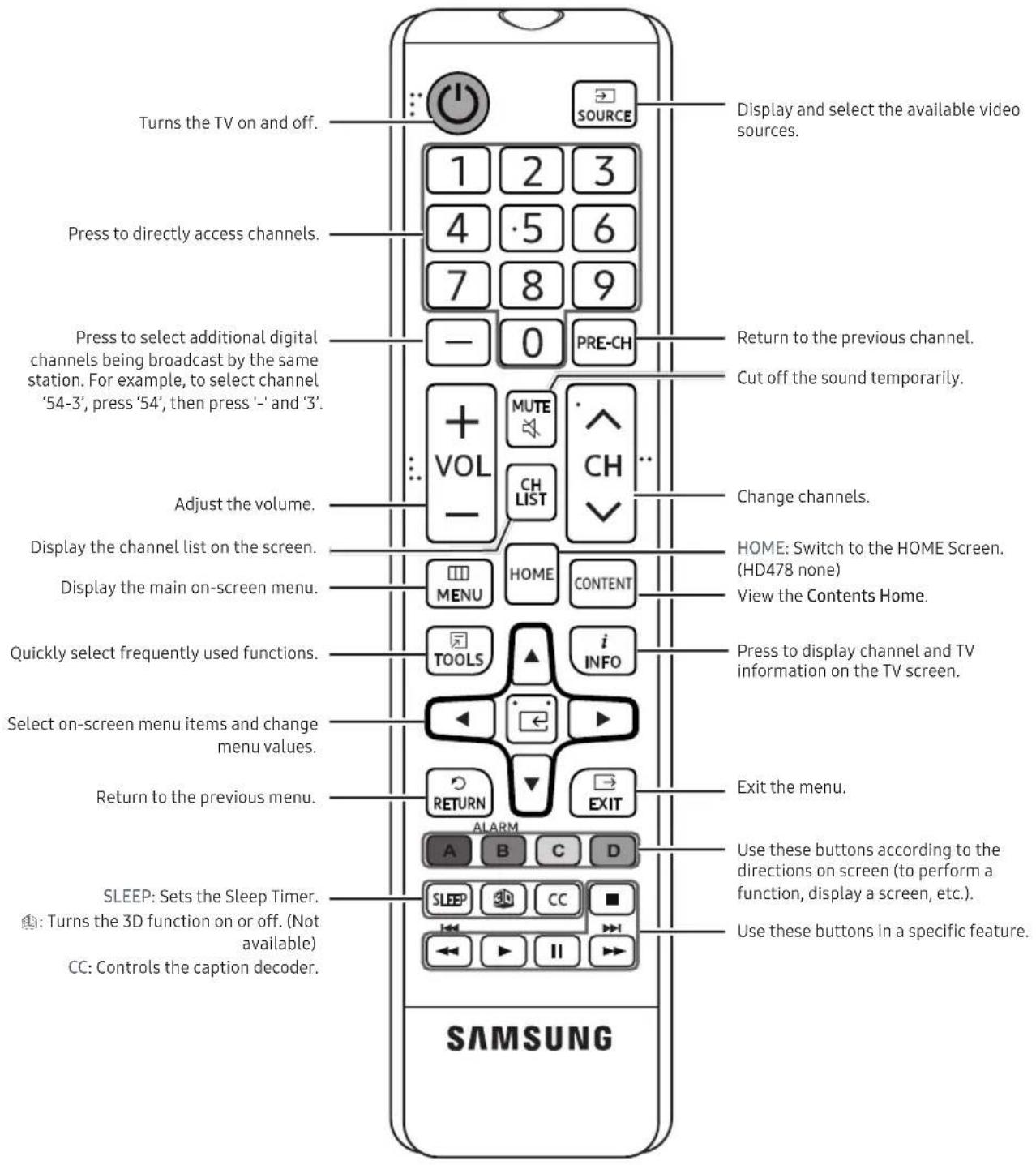
Installing batteries (Battery size: AAA)
Rear of the Remote
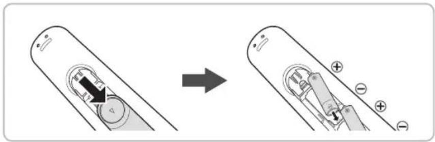
After you have installed the batteries, use a screwdriver to screw in the screw that holds the battery cover closed.
Installing Batteries into the Remote (battery size: AAA)
Match the polarity of the batteries to the symbol in the batter compartment.
NOTE
• Use the remote control within 23\~33 feet of the TV.
- Bright light may affect the performance of the remote control. Avoid using near fluorescent lights or neon signs.
• The color and shape of the remote may vary depending on the model.
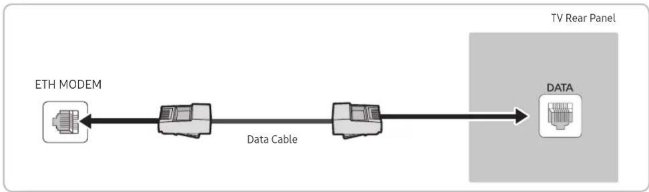
Connecting the TV to the Lodgenet game controller or a STB of a SI vendor
HE470/HE477
flowchart
graph LR
    A["ETH MODEM"] -->|Data Cable| B["TV Rear Panel"]
    B --> C["DATA"]
- Connect the DATA jack of the TV to the ETH MODEM jack of the STB (SBB) with the Data cable.
The "ETH MODEM" jack name that you connect the Data Cable to may differ depending on the SBB or STB type.
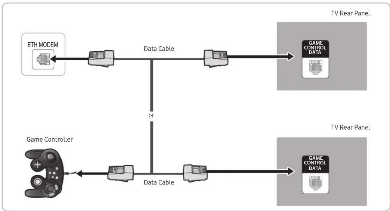
HE478
flowchart
graph LR
    A["ETH MODEM"] --> B["Data Cable"]
    B --> C["Game CONTROL DATA"]
    D["Game Controller"] --> E["Data Cable"]
    E --> F["Game CONTROL DATA"]
    style A fill:#f9f,stroke:#333
    style D fill:#f9f,stroke:#333
    style B fill:#ccf,stroke:#333
    style C fill:#cfc,stroke:#333
    style F fill:#fcc,stroke:#333
- Connect the LodgeNet game controller to the TV's GAME CONTROLLER DATA jack of the TV.
- Connect the GAME CONTROL DATA jack of the TV to the ETH MODEM jack of the STB (SBB) with the data cable.
The "ETH MODEM" jack name that you connect the Data Cable to may differ depending on the SBB or STB type.
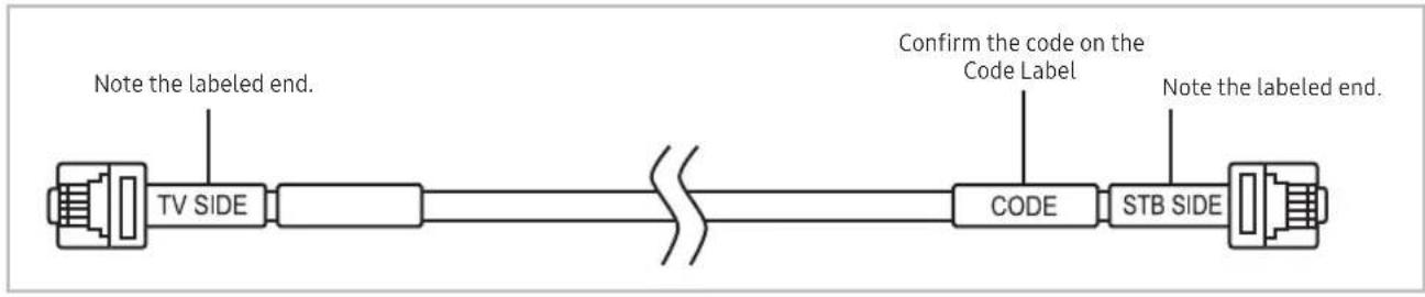
List of SI Vendors and Compatible Data Cables Supplied with the TV (some cable sold separately)
- Confirm you are using the correct data cable for your SI vendor. Refer to the code label on the data cables.
- Contact your nearest dealer or your SI Vendor to buy the data cable not included in the TV.
| SI Vendor Cable code Pin assign Remark | |||
| SamsungOCCEnseoGuest-Tek | BN39-00865B | 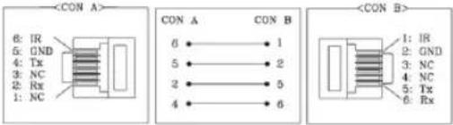 | |
| NXTV BN39-01011B | 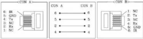 | ||
| nStreams BN39-01110A | 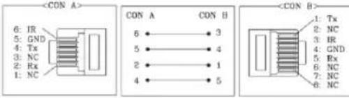 | ||
| MTI BN39-01011C | 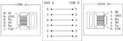 | ||
Operation Specification of Data Cable(RJ12) : TTL
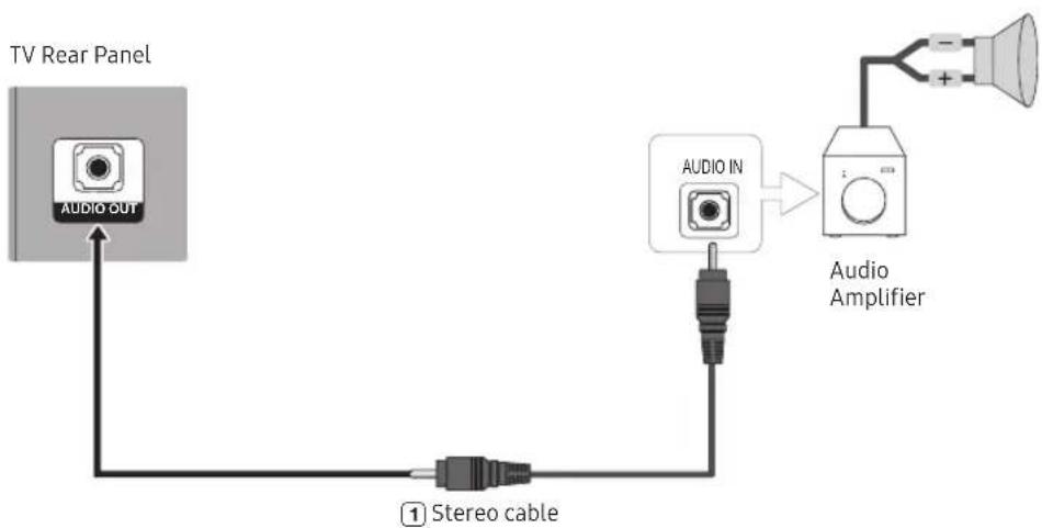
Connecting the Audio Output to an Audio Amplifier
flowchart
graph TD
    A["TV Rear Panel"] --> B["AUDIO OUT"]
    B --> C["1 Stereo cable"]
    C --> D["AUDIO IN"]
    D --> E["Audio Amplifier"]
    E --> F["+"]
    E --> G["-"]
- Connect the AUDIO OUT port of the TV to the Audio In port of an audio amplifier with a stereo cable. (Stereo cable not provide)
Connecting the MediaHub HD
Output to any external source connected to MediaHub HD on the hotel desk.
(Inlay sample may vary depending on the model.)
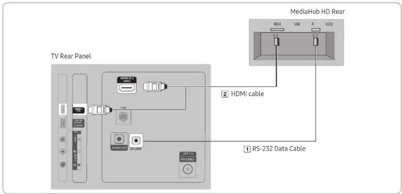
- Connect the RJP port of the TV and the RS/232 port of the MediaHub HD.
- Connect the 1 or 2(DVI) or 2(ARC) port of the TV and the HDMI port of the MediaHub HD.
- MediaHub HD
- The MediaHub HD is a hardware module that has different Audio Video inputs (A/V, Audio, PC, HDMI and USB) and corresponding outputs. The corresponding output sources connect from MediaHub to the TV. MediaHub communicates with the TV via RS232. Hot Plug & Play is a function that allows hotel guests to connect an external source to the MediaHub. MediaHub communicates with the TV by sending messages regarding Active/Inactive sources. The TV switches to the Active external source.
- You have to connect the HDMI of the MediaHub to the HDMI IN(set in hotel option-Remote Jack Pack-HDMI option) port of the TV.
-When the TV is on, connect the TV and the RJP within 10 seconds.
- Special features
-Plug & Play
-Auto Detection
Connecting the RJP (Remote Jack Pack)
Connect the input jacks on the TV to the RJP. The RJP lets guests connect audio and video sources to the TV. (Inlay sample may vary depending on the model.)
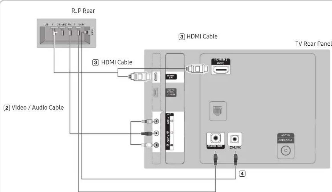
① PC Audio cable
- Connect the AUDIO OUT port of the TV to the PC/AUDIO port of the RJP.
- Connect the AVIN VIDEO/L-AUDIO-R port of the TV to the RCA port of the RJP.
- Connect the HDMI IN port of the TV to the HDMI port of the RJP.
- Connect the EX-LINK port of the TV to the RS/232 port of the RJP.
This Samsung TV is compatible with the TeleAdapt TA-7610 RJP only.
- RJP (Remote Jack Pack): The RJP is a hardware module that has different Audio Video inputs (A/V, Audio, PC and HDMI) and corresponding outputs. The corresponding outputs are connected from the RJP to the TV. The RJP communicates with the TV via RS232. The RJP communicates with the TV by sending messages regarding Active/Inactive sources.
- A group of hotel menu items let you assign numbered priorities to the jacks of the RJP. (See page 25). 1 is the highest priority and 3 is the lowest. When a guest connects external sources to the RJP jacks, the TV will automatically switch between sources based on the priority you have assigned them in the Menu. For example, lets say AV is set to 1 and HDMI to 2. If a guest has attached a device to the HDMI jack, and then plugs a device into the AV jack, the TV automatically switches to the device plugged into the AV jack (the jack with the higher priority). Note that a guest can also switch between devices manually by pushing a button on the RJP.
When you set up the RJP, connect the RJP to HDMI 1, 2, or 3 or AV.
- To reset the RJP to its factory default state, press the AV and HDMI buttons simultaneously for 10 seconds. When all button LEDs blink 5 times, the RJP reset is complete.
- The RJP will automatically turn off any LEDs after 5 minutes to avoid unnecessary light pollution in the hotel room. The LEDs that were turned off will turn on again if the guest touches any of the buttons and the 5 minute timer will restart. If the guest then touches another source button, the TV will change to the selected source and the corresponding LED will be lit.
- After an RJP Reset or a TV Power OFF/ON, it takes approximately 10 seconds to establish communications between the TV and the RJP.
- The following table shows the approximate time in seconds it takes to switch from the TV to an input source, based on assigned or default priorities.
Scenario 1: When no inputs are connected.
| Source To Connect | |
| AV 2 Sec | |
| PC 0.7 Sec | |
| HDMI 3.9 Sec | |
Scenario 2: When two or more inputs are connected to the RJP and one of the input sources is disconnected and then reconnected.
| Source Disconnect To Connect | Total | ||
| AV | 4.5 Sec | 2 Sec | 6.5 Sec |
| PC | 0.7 Sec | 0.7 Sec | 1.4 Sec |
| HDMI 3.9 Sec | 3.9 Sec | 7.8 Sec | |
An example: If the RJP has all its live sources (AV, PC, and HDMI) connected, AV has been assigned the highest priority, the RJP is in HDMI mode, and a guest removes and reconnects the AV source, the minimum time required to switch to the AV source is 6.5 seconds.
- To play audio devices (Ipods, MP3 devices, etc.) through the RJP, you must turn Music Mode AV in the menu on. (See page 30)
- Music mode in the TA-7610 RJP is supported by the AV jack only. HDMI Music mode is available for the Guestlink RJP only.
Setting the Hotel Option Data
To let you control how the TV functions when in Hotel mode, the TV has two Hotel mode menus, the Stand-alone mode menu and the Interactive mode menu. The menu items that differ between the menus are listed below.
Menu items in the Stand-alone mode only:
-SI Vendor : OFF / Smoovie / SSCP
-REACH Server and its submenus.
Menu items in the Interactive mode only:
–SI Vendor: Samsung and other vendors.
All other items appear in both menus.
To access the menus, press MUTE → 1 → 1 → 9 → ENTER on your Samsung remote.
After a menu appears, follow these general directions to navigate and change values:
- Use the Up and Down arrow buttons on the Samsung remote to move from menu item to menu item.
- Press the ENTER← or Left or Right arrow buttons to select a menu item. The screen displays that menu item only.
- Press the Left or Right arrow button to change a value. The Right arrow button increases numerical values. The Left arrow button decreases numerical values.
- When the screen is displaying one menu item, you can press the Up or Down arrow button to display the next or previous menu item.
- Press the RETURN or MENU button to exit the current menu item and go to a higher menu level or the Main menu.
- To exit a Hotel mode menu, turn off the TV, and then turn it on again. Any changes you made are saved except changes to SI Vendor. For changes to SI Vendor, you must turn the TV off, wait until the Standby light glows steadily, then unplug the TV, wait for the Standby light to go off, and then plug the TV in again.
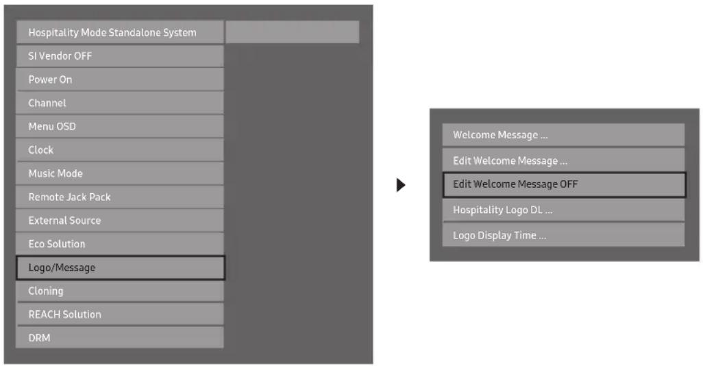
| Hospitality Mode Standalone System | |
| SI Vendor OFF | |
| Power On | |
| Channel | |
| Menu OSD | |
| Clock | |
| Music Mode | |
| Remote Jack Pack | |
| External Source | |
| Eco Solution | |
| Logo/Message | |
| Cloning | |
| REACH Solution | |
| Security Mode | |
| DRM |
To change menus, follow these steps:
- Highlight the Hospitality Mode menu item in the top left corner of the menu.
- Press the left or right arrow button on the Samsung remote. Only the Hospitality Mode menu item is displayed.
- Press the left or right arrow button to change the Hospitality Mode item from Standalone to Interactive or from Interactive to Standalone.
- Press the Return or Menu button on the remote. The entire menu re-appears with your selection displayed in the Hospitality Mode field.
After you have set the values in one TV, you can clone those values to multiple TVs. See USB Cloning on page 35.
Menu Items (some options may be different depending on model, please refer to the set)
To Enter this menu: Press the MUTE → 1 → 1 → 9 → ENTER← buttons in order.
To exit from this menu: Power Off (or Power Off and unplug if you have changed SI Vendor), and then turn on again. Any changes you made are saved.
| Menu Item | initial Value Description | ||
| Hospitality Mode | Hospitality Mode | Standalone (Interactive for 478 models) | Select Hospitality mode.Interactive mode: TV works with an SI STB or SBB.Standalone mode : TV works alone, without an SI STB or SBB. |
| SI Vendor SI | Vendor | OFF (Samsung for 478 models) | Interactive mode: Samsung / OCC / MTI / Nstreams / Enseo / Cardinal / Guestek / SeaChange / MDC / InnvueStandalone mode: OFF / Smoovie / SSCP |
| Power On | Power On Channel Num | Last Saved | Set the default values that will be applied when the TV is turned.User Defined: Lets you set Power On Channel and Channel Type manually. See Power On Channel and Channel Type below.Last Saved: If you select this item, when the TV is turned on, it displays the channel it was displaying when it was turned off. |
| Power On Channel Num | ... When | the TV is turned on, it switches automatically to this channel. | |
| Power On Channel Type | ... | Select channel band: AIR (analog air band), DTV (digital air band), CATV (analog cable band), CDTV (digital cable band). | |
| Power On Volume | Last Saved | User Defined: Lets you set the Power On Volume manually. See Power On Volume below.Last Saved: When the TV is turned on, it returns to the volume that had been set when the power had been turned off. | |
| Power On Volume Num | ... The TV | turns on with this Volume Level in Stand Alone Hospitality mode. | |
| Min Volume 0 | The minimum Vol | Volume Level the user can set in Stand Alone Hospitality mode. | |
| Max Volume 100 | The maximum | Volume Level the user in Stand Alone Hospitality mode. | |
| Power On Source | TV | Select the input source the TV displays when turns on. | |
| Power On Optioninitial Value Description | Last Option | Determines the TV's state when power returns after a power failure or after you have unplugged the TV and then plugged it in again.Last Option: Returns to its last Power state. If it was in Stand-by, it returns to Standby. If it was on, it turns on.Power ON: When the power returns, the TV turns on.Standby: When the power returns, the TV enters the Standby mode. | |
| Menu Item | |||
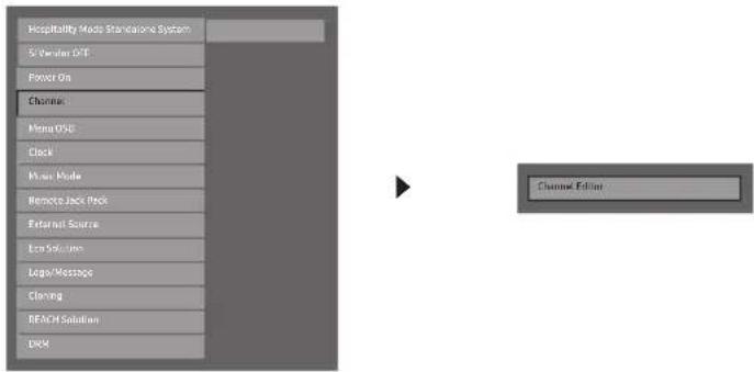
| Channel | Channel Setup | Gives you direct, immediate access to some of the Channel menu functions on the user Channel menu such as Auto Program, Antenna selection, etc. | |
| Channel Editor | The Channel Editor lets you edit the channels stored in the TV's memory. Using Channel Editor you can:Change the channel numbers and names, and sort the channels in your desired channel number order.Apply the video mute to channels you select. The video mute blanks out the video from a channel and outputs only the sound while displaying a speaker icon on the screen. The Channel Editor also lets you view information about each channel easily, without your having to display each channel directly. | ||
| Channel Bank Editor | The Channel Bank Editor in conjunction with the SMOOVIE remote lets you control the channels guests have access to the channels a guest can access depend on the Bank Card installed in their SMOOVIE remote. | ||
| Mixed Channel Map OFF | ON: Display the cable program channels with air program channels on the channel list at the same time.OFF: Display the cable program channels or air program channels on the channel list one time. (can't display them both at the same time) | ||
| Dynamic SI OFF | ON: Check the DTV Program channel number. (If Dynamic SI is On, it is not available to edit DTV channels in Channel Editor.)OFF: Do not check the DTV Program channel number. (If Dynamic SI is Off, it is available to edit DTV channels in Channel Editor, but additional DTV channel program number update is not supported.) | ||
| Menu OSD | Picture Menu Lock OFF Enable or disable the Picture Menu. | ||
| Menu Display ON | ON: The Main Menu is displayed.OFF: The Main Menu is not displayed. | ||
| Tools Display OFF | ON: The Tools quick acess is displayed.OFF: The Tools quick acess is not displayed. | ||
| Channel Menu Display | OFF | OFF: The auto program is not displayed.ON: The auto program is displayed. | |
| Panel Button Lock Unlock | Turning the front panel (local key) operations on/off.Unlock: Unlocks all panel keys.Lock: Locks all panel keys.OnlyPower: Locks all panel keys except the Power panel key.Menu/Source: Locks the Menu and Source panel keys. | ||
| Home Menu Display ON | OFF: The Home Menu is not displayed.ON: The Home Menu is displayed. (HD478 model not have) | ||
| Home Menu Editor Home Menu is displayed. (HD478 model not have) | |||
| Home Menu Auto Start | ON | ON: The Home Menu is Auto Start.OFF: The Home Menu is not Auto Start. (HD478 model not have) | |
| Clock | Clock Type | OFF | OFF: Close SW Clock.SW Clock: Open SW Clock. |
| Local Time | Manual | Select the way to update the clock dataUse clock data from a DTV channel to set the clock automatically or set the clock manually when the TV is in stand-alone mode. | |
| Timer Type | Wake Up | WakeUp: you can set a specific time for the TV to turn on automatically.OnOff: Have you TV turn itself on/off automatically at a specified time. you can set three Times the most at the same time. | |
| Time Channel Type | ... | Use clock data from which DTV channel to set the clock. | |
| Time Channel Num | ... | DTV channel Number. | |
| Music Mode | Music Mode AV OFF | Allows music output from an mp3/audio player connected to an AV Input Source on the TV. When on, you can hear sound from the player through the TV whether there is a video signal or not. Also mutes the video so the TV does not display a picture when a guest is playing music. The TV's backlight, however, remains on. | |
| Music Mode Backlight | OFF | When set to Off, the TV's backlight is turned off entirely when a guest uses the Music mode. To save energy, set to Off. | |
| Remote Jack Pack | Priority AV 1 | If the jack priority is set, the corresponding source is automatically set when a jack is inserted according to the jack priority. (only for TA-7610 RJP device) | |
| Priority HDMI 2 | If the jack priority is set, the corresponding source is automatically set when a jack is inserted according to the jack priority. (only for TA-7610 RJP device) | ||
| AV Option | AV | Select RJP AV Source (Source selection depends on Model). (only for TA-7610 RJP device) | |
| HDMI Option | HDMI 1 | Select which HDMI source of the TV is connected to the RJP jack. (HDMI1/HDMI2/HDMI3) | |
| HDMI Music Mode OFF | Allows music output from an mp3/audio player connected to an HDMI Input Source. When on, you can hear sound from the player through an HDMI input of the RJP whether there is a video signal or not. (This option is only compatible with the Guest link RJP.) | ||
| External Source | USB Pop-up Screen Default | When USB is connected to the TV :Default: a popup window appears.Automatic: Opens the USB contents menu automatically.Disable: Neither the popup window nor the menu appears. | |
| External Source Banner | ON | If set to On, the TV displays the External Source Banner (information) when you change the TV source to another external input, press the Info key, or turn the TV on.ON: The External Source information is displayed on the TV screen.OFF: The External Source information is not displayed on the TV screen. | |
| Auto Source | OFF | ON: When an external input source is connected to the TV, the TV identifies the input source, and then automatically switches to that input source.OFF: Auto Source function is Off. | |
| Anynet+ Return Source | Power On Src | Select the return TV source after stopping an Anynet+(HDMI-CEC) connection. (This fuction is especially useful for the Guestlink RJP.) | |
| Eco Solution | Energy Saving | Off | Adjusts the brightness of the TV to reduce power consumption.OFF: Turns off the energy saving function.Low: Sets the TV to low energy saving mode.Medium: Sets the TV to medium energy saving mode.High: Sets the TV to high energy saving mode. |
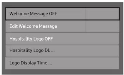
| Logo/Message | Welcome Message | OFF | Displays a the Welcome Message for 5 seconds when the TV turns On. |
| Edit Welcome Message | Edits the Welcome Message. | ||
| Hospitality Logo | OFF | Turns the Hospitality logo feature On or Off, If On, when the TV is turned on, the Logo is displayed, before the signal from the initial source, for the amount of time set in "Logo Display Time". | |
| Hospitality Logo DL | ... | Downloads the Hospitality logo.Hospitality logo file requirements:BMP or AVI files only.Max file size: BMP - 960 X 540. AVI - 30MB.The file can only be named samsung.bmp or samsung.avi. | |
| Logo Display Time ... | Hospitality Logo Display Time (3/5/7 seconds). | ||
| Menu Item initial Value Description | |||
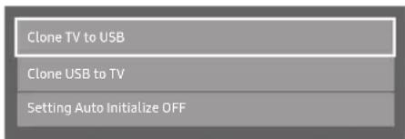
| Cloning | Clone TV to USB Clone the current TV options to a USB memory device. | ||
| Clone USB to TV Clone the saved TV options on a USB memory device to the TV. | |||
| Setting Auto Initialize | OFF | If you set Setting Auto Initialize to On, and the TV's power is turned off and on, the guest side menu items are restored to their cloned values. See page 39. | |
| REACH Solution | REACH 3.0 OFF | OFF: Close REACH 3.0.ON: Open REACH 3.0. | |
| REACH Channel ... | 87 : Assign a DTV channel number to carry the update REACH data. This channel number must be the same as the number set on the Reach server. | ||
| Group ID ... | All : Select the group ID of the REACH server. (Refer to the REACH server manual for more details) | ||
| IPG Room Type ... | You can receive up to 3 EPG information headed to the Americas according to Room Type from SI, and it displays the appropriate channel list and EPG information according to the value set on TV. For IPG Room Type, there are Default / Public / Roomtype 3 within the hotel Factory Install menu, and its default value is Default. | ||
| Ticker OFF | ON: The TICKER content is displayed.OFF: The TICKER content is not displayed. | ||
| REACH Update Time ... | Lets you set when data such as updated SW, cloning files, and S-LYNC REACH contents is downloaded from the REACH server to the TV :1hour : Every hour2hour : Every 2 hours12:00 am : every 12:00 a.m.2:00 am : every 2:00 a.m.12:00 pm : every 12:00 p.m.2:00 pm : every 2:00 p.m. | ||
| REACH Update Immediate | ... | ON : Whenever the TV enters standby mode (the power cord is plugged in and the power is off), the REACH data is updated on the TV.OFF : The REACH data is only updated on the TV at the REACH server update time. | |
| Room Number ... Setting Room Number. | |||
| REACH Server Version | 0000 0000 : Displays the current REACH data version. | ||
| Security | Password Input | Input Password 00000000. | |
| Password Setting | ... Set new Password. | ||
| Password Reset ... Reset Password to 00000000. | |||
| Security Mode | ... Security Mode ON or OFF. | ||
| USB | ... USB Disable or Enable. | ||
| HDMI | ... HDMI Disable or Enable. | ||
| DRM | DRM Mode | OFF477 / 478:pro:idiom | Configures CAS support.OFF: Turns off CAS support.LYNK DRM : Select to turn on S-LYNK DRM CAS support only.Pro:idiom : Select to turn on Pro:Idim CAS support only. (only for 477/478 and above models)LYNK DRM,PI : Select to have the TV support S-LYNK DRM CAS and Pro:Idiom CAS. (only for 477/478 and above models) |
| PI AES Data | 0x0000 | Displays the current state of Pro:idiom AES. (only for 477/478 and above models) | |
| PI AES Log OFF | PI AES Log consists of Pro:idiom AES diagnostic register, here after referred as AESD, values. These register log will help us diagnose PI key loss issue in the field and provide solution for it. (only for 477/478 and above models) | ||
| View PI AES Log ... | Displays Pro:idiom AES Log OSD (only for 477/478 and above models) | ||
| Menu Item | initial Value Description | ||
| System | Self Diagnosis for TV | Lets you check the state of the TV picture and sound.Picture Test: Use to check for picture problems. If the problem appears in the test picture, select YES, and then follow the directions on the screen.Sound Test: Use to check for sound problems. If the problem occurs during the test, select YES, and then follow the directions on the screen. | |
| Self Diagnosis for HTV | Lets you check the state of Pro:Idiom and its communication with the SI STB or SBB. If you have any problems with the Pro:idiom encryption channel or the communications with the SI STB or SBB, use this diagnosis function. If Pro:Idiom DTV Channel Key Loss appears to have failed and the Pro:Idim encryption channel has failed to play content, first check the broadcasting systems related to Pro:Idiom encryption. If your broadcasting system does not have a problem, contact Samsung Service. If STB SI Vendor Setting appears to have failed and communication with the SI STB or SBB has failed, first check your SI STB or SBB. If your SI STB or SBB does not have a problem, contact to Samsung Service. | ||
| SW Update Lets | you upgrade the TV SW with a USB memory stick. See Page 42. | ||
| Service Pattern OFF | Lets you check the state of the TV picture by displaying picture test patterns. Press the Menu button to turn off the test patterns and exit. | ||
| ATV Cable AGC Gain | Default | Lets you control the AGC gain of the analog cable channels. Don't change the default value unless problems occur. | |
| DTV OpenCable AGC Gain | Default | Lets you control the AGC gain of the digital cable channels. Don't change the default value unless problems occur. | |
| Sound Bar Out OFF | ON: TV speaker sound will be mute. Sound will come out through HDMI. You must connect the Sound Bar to hear the sound.OFF: Sound will come out through TV speakers normally. | ||
| Contact Samsung Samsung Contact information | |||
| Standby LED ON | ON: The LED light in fuction will be in red light.OFF: The LED light in fuction will be light off. | ||
| TV Reset Returns all settings on the TV to their factory defaults. | |||
REACH (Remote Enhanced Active Control for Hospitality) is a professional, interactive remote controller that lets you deliver TV firmware updates, cloning data, channel mapping changes, S-LYNK REACH contents, and TICKER contents through RF DTV to several hundred hospitality TVs simultaneously. The REACH functions are available only in stand-alone mode. The REACH Server is sold separately. Refer to the REACH server manual enclosed with the REACH server product for more operating information.
Security Mode highlight after input password.
Security Mode off, HDMI/USB/TTX function response will back to enable status.
Security Mode On, HMDI/USB/TTX function response will according which setting value.
When change setting value of Mix Channel Map and Dynamic SI, Must do power off/on, then can go to channel Editor confirm channel status.
Sports(or Soccer) Mode TOOLS
MENU → Applications → Sports(or Soccer) Mode → ENTER
This mode provides optimized condition for watching sports games.
- A (Zoom): Pause playback and divide the picture into 9 parts. Select a part to zoom it in. Press this button again to resume.
If you turn the TV off while watching Sports(or Soccer) Mode, the Sports(or Soccer) Mode will be disable.
Welcome Message
The Welcome Message feature displays a custom message on the TV every time it is turned on.
–Welcome message settings are in the Hotel Option Menu.
- Set Welcome Message to ON to display the message when the TV is powered on.
- You can make the Welcome Message up to 25 characters long and edit it in the Hotel Service menu.
–Welcome Message supports the following characters:
Capital Letters from A to Z.
- You can edit the Welcome Message by using the remote's navigation, color, and Enter buttons in the "Edit Welcome Message" OSD (See the illustration below.)
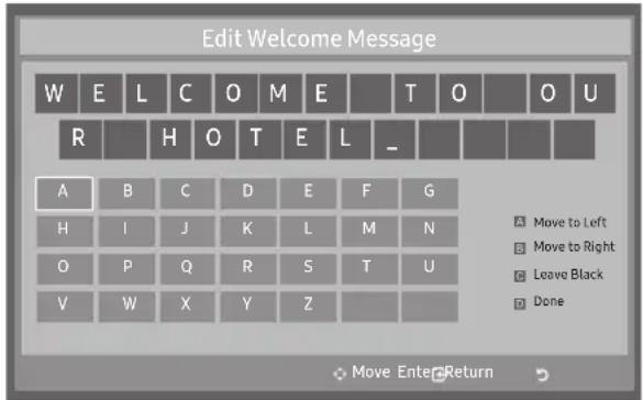
Below are the general directions for navigating and changing letters on the Edit Welcome Message screen:
- Press the A button on the remote to move to the left in the message.
- Press the B button to move to the right.
- After you have selected a position in the message, use the arrow buttons on your remote to select a letter in the alphabet below the message.
- Press Enter to place a letter into the position you selected.
- Press the C button to erase a letter in a position or enter a blank.
- Press Return or the D button to exit.
Hotel Logo
The Hospitality Logo function displays the Hotel's picture image when the TV is powered on.
–Hospitality Logo settings are the Hotel mode menus.
- The Logo Download and Logo Display Menu items are enabled when you turn the Hospitality Logo option on.
- If there is a logo image stored in memory and the Hospitality Logo option is on, the Hospitality logo is displayed when the TV is turned on.
- The Hospitality logo is not displayed when the Hospitality found Logo option is off, even if the logo image has been loaded into the TV.
- Hospitality Logo
- This option lets you choose whether the Hospitality Logo image is displayed or not.
-Initial value is OFF.
-Can be set to OFF or ON.
- When set to ON, the Logo Download and Logo Time Display menu items become accessible.
- Hospitality Logo DL
- This option lets you download the logo image to the TV's memory from a USB device.
—A wait message appears while the image is being copied to the TV. - A "completed" message appears when the copy operation finishes successfully.
- The word "failed" appears if the copy operation was unsuccessful.
- No USB appears if no USB device is connected.
- No File appears if there is no file to copy on the USB device or the file is in the wrong format (must be a BMP or AVI file). If No File appears and there is a logo file on the USB device, check the file format.
- Logo File Format
–The TV supports only BMP and AVI format.
–The file name must be samsung.bmp or samsung.avi.
–The maximum resolution of the BMP format is 960 x 540.
–The maximum file size for AVI format is 30MB.
—The TV does not change the size or scale of the image.
Video Codec: H.264 /MPEG-4 /MPEG2
Bit Rate: below 10 Mbps
Frame Rate: 24\~30
Resolution: 640*480 | 1920*1080
—The TV does not change the size or scale of the image.
The USB Cloning function lets you download user-configured settings (Picture, Sound, Input, Channel, Setup, and Hotel Setup) from one TV to a USB device, and then upload these settings from the USB device to other TV sets. This lets you create a standard file of settings and distribute that standard file to all the TVs in your facility.
- Cloning from TV to USB: Copies stored menu settings from a TV to a USB device.
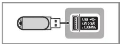
- Insert a USB drive into the USB port on the rear or side of the TV.
- Enter the hotel option menu by pressing buttons in order. MUTE → 1 → 1 → 9 → ENTER
- Press the ▲ or ▼ button to select Clone TV to USB, and press the ENTER← button.
- When the message Clone TV to USB is displayed. Press the ENTER button.
- The TV displays one of the following messages:
• In Progress: Copying data to USB.
• Completed: Copy was successful.
• Failed: Copy was not successful.
• No USB: USB is not connected.
The clone folder will be labeled T-NT16LAKUCB.
The cloned values include the values on the Guest side menu (brightness, picture size, contrast, etc.) and the Hotel side menu.
- Cloning from USB to TV : Copies menu settings in a USB device to a TV.
Shortcut: Turn the TV off, insert the USB device, turn the TV on, and then press the ENTER button for 5 seconds.
To clone data to the TV using the Hotel menu, follow these steps:
- Turn the TV off.
- Insert the USB drive into the USB port on the rear or side of the TV.
- Turn the TV on.
- Enter the Interactive menu by pressing these buttons in order. MUTE → 1 → 1 → 9 → ENTER
- Press the ▲ or ▼ button to select "Clone USB to TV", and then press the ENTER← button.
- The message Clone USB to TV is displayed. Press the ENTER button.
- The TV displays one of the following messages:
• In Progress: Copying data to TV.
• Completed: Copy was successful.
• Failed: Copy was not successful.
• No USB: USB is not connected
- No File: There is no file to copy on the USB device. If you get a No File message, check the folder on your USB device. The folder name should be T-NT16LAKUCB.
Tables that list the settings that are cloned in the Interactive and Standalone Hotel Menus begin on the next page.

Settings Cloned in the Hotel Menu
| Menu Item Cloning Support | |
| Hospitality Mode Yes | |
| SI Vendor Yes | |
| Power On Channel Yes | |
| Power On Channel Num Yes | |
| Power On Channel Type Yes | |
| Power On Volume Yes | |
| Power On Volume Num Yes | |
| Min Volume Yes | |
| Max Volume Yes | |
| Power On Source Yes | |
| Power On Option Yes | |
| Channel Setup No | |
| Channel Editor No | |
| Mixed Channel Map | No |
| Dynamic SI | No |
| Picture Menu Lock | Yes |
| Menu Display | Yes |
| Tools Display | Yes |
| Channel Menu Display | Yes |
| Panel Button Lock | Yes |
| Home Menu Display | Yes |
| Home Menu Editor | Yes |
| Home Menu Auto Start | Yes |
| Clock Type | Yes |
| Local Time | Yes |
| Timer Type | Yes |
| Time Channel Type | Yes |
| Time Channel Num | Yes |
| Music Mode AV | Yes |
| Music Mode Backlight | Yes |
| Priority AV | Yes |
| Priority HDMI | Yes |
| AV Option | Yes |
| HDMI Option | Yes |
| HDMI Music Mode Yes | |
| USB Pop-up Screen | Yes |
| External Source Banner Yes | |
| Auto source | Yes |
| Anynet+Return Source | Yes |
| Energy saving | Yes |
| Welcome Message Yes | |
| Edit Welcome Message Yes | |
| Hospitality Logo No | |
| Hospitality Logo DL Yes | |
| Logo Display Time Yes | |
| Clone TV to USB Yes | |
| Clone USB to TV Yes | |
| Setting Auto Initialize Yes | |
| REACH 3.0 Yes | |
| REACH Channel Yes | |
| Group ID No | |
| IPG Room Type No | |
| Ticker Yes | |
| REACH Update Time Yes | |
| REACH Update Immediate | Yes |
| Room Number | Yes |
| REACH Server Version | Yes |
| Password Input | Yes |
| Password Setting | No |
| Password Reset Yes | |
| Security Mode | Yes |
| USB | Yes |
| HDMI | Yes |
| DRM Mode No | |
| PI AES Data | No |
| PI AES Log | Yes |
| View PI AES Log | No |
| Self Diagnosis for TV No | |
| Self Diagnosis for HTV No | |
| SW Update No | |
| Service Pattern | Yes |
| ATV Cable AGC Gain | Yes |
| DTV Open Cable AGC Gain | Yes |
| Sound Bar Out | Yes |
| Contact Samsung | No |
| Standby LED | Yes |
| TV reset | No |
Multi Code Remocon
A Multi Code Remocon is a special remote which is designed to control multiple TVs.
This function is useful where there is more than one TV in a location.
You can control up to 10 TVs with a different ID code of each remote with no conflicts between the TVs. ID numbers are displayed on each TV's OSD.
The Initial ID code for each TV is "0".
- You can set and reset the ID code in Analog TV mode or PC mode. (Not available in DTV mode.)
- You can set the ID code to any digit from 0 to 9.
-To set a TV's ID code, follow these steps:
- Aim the remote at the TV, and then press the MUTE button and the RETURN button simultaneously for more than 7 seconds. When you stop pressing the buttons, the TV displays the current ID in the middle of the screen and the words, "Remote control code is set to x. If you want to change the Remote control code, enter the digit you want to change."
- Press the number on the remote you want to assign to the TV. The TV displays the following words: "Remote control code is changed to x."
The TV will display the OSD until you press the EXIT button.
See the example below.

Remote control code is set to 0. If you want to change Remote control code, enter the digit you want to change.
Example: After you see the message above, if you press 1, the TV and Remote will be set to ID code 1. The TV then displays the following message: "Remote control code is changed to 1"
The TV can then only be controlled by a remote which has the same ID code (1).
- To reset the ID code, press the MUTE button and the EXIT button simultaneously for more than 7 seconds. When you stop pressing the buttons, the ID codes of the TV and Remote are reset to "0". "Remote control code is set to 0." appears on the TV.
Setting Auto Initialize
When you clone settings from one TV to another, you clone both the guest side menu and hotel side menu settings: Picture, Sound, Input, Channel, Setup, and Hotel Setup. This lets you set nearly all of the menu values on your hospitality TVs to the same, standard settings. If you allow guests access to the guest side menus, for example the Picture menu, they can change the settings in those menus so they are no longer standard. If you set the Setting Auto Initialize function to on the TV automatically restores (initializes) any guest-side menu values to the cloned, standard values when the TV is turned off and then turned on again. Note that Setting Auto Initialize works on cloned guest side menu values only. Settings which have not been cloned are ignored.
The table below lists the settings that are restored to their cloned values when you set the Setting Auto Initialize function to On.
| Menu Menu | Item Menu Menu Item | ||
| Picture Menu | Picture Mode | Sound Menu | Sound Mode |
| Backlight Sound Effect | |||
| Contrast DTS TruSurround | |||
| Brightness DTS TruDialog | |||
| Sharpness Equalizer | |||
| Color Speaker Settings | |||
| Tint (G/R) Speaker Select | |||
| Picture Size Auto Volume | |||
| Picture Size TV Installation Type | |||
| Position Reset Sound | |||
| PIP | System Menu | Menu Language | |
| Advanced Settings Time | |||
| Dynamic Contrast Clock | |||
| Black Tone | Sleep Timer | ||
| Flesh Tone | Wake-up Timer | ||
| RGB Only Mode | Eco Solution | ||
| Color Space | Energy Saving | ||
| White Balance | Eco Sensor (only for 40" and above models) | ||
| Gamma | No Signal Power Off | ||
| Motion Lighting | Auto Power Off | ||
| Picture Option | Auto Protection Time | ||
| Color Tone Change PIN | |||
| Digital Clean View | General | ||
| MPEG Noise Filter | Game Mode | ||
| HDMI Black Level | Boot Logo | ||
| Film Mode | Anynet+ (HDMI-CEC) | ||
| Picture Off Anynet+ (HDMI-CEC) | |||
| Reset Picture | Auto Turn Off | ||
| DivX® Video On Demand |
Hotel Plug & Play
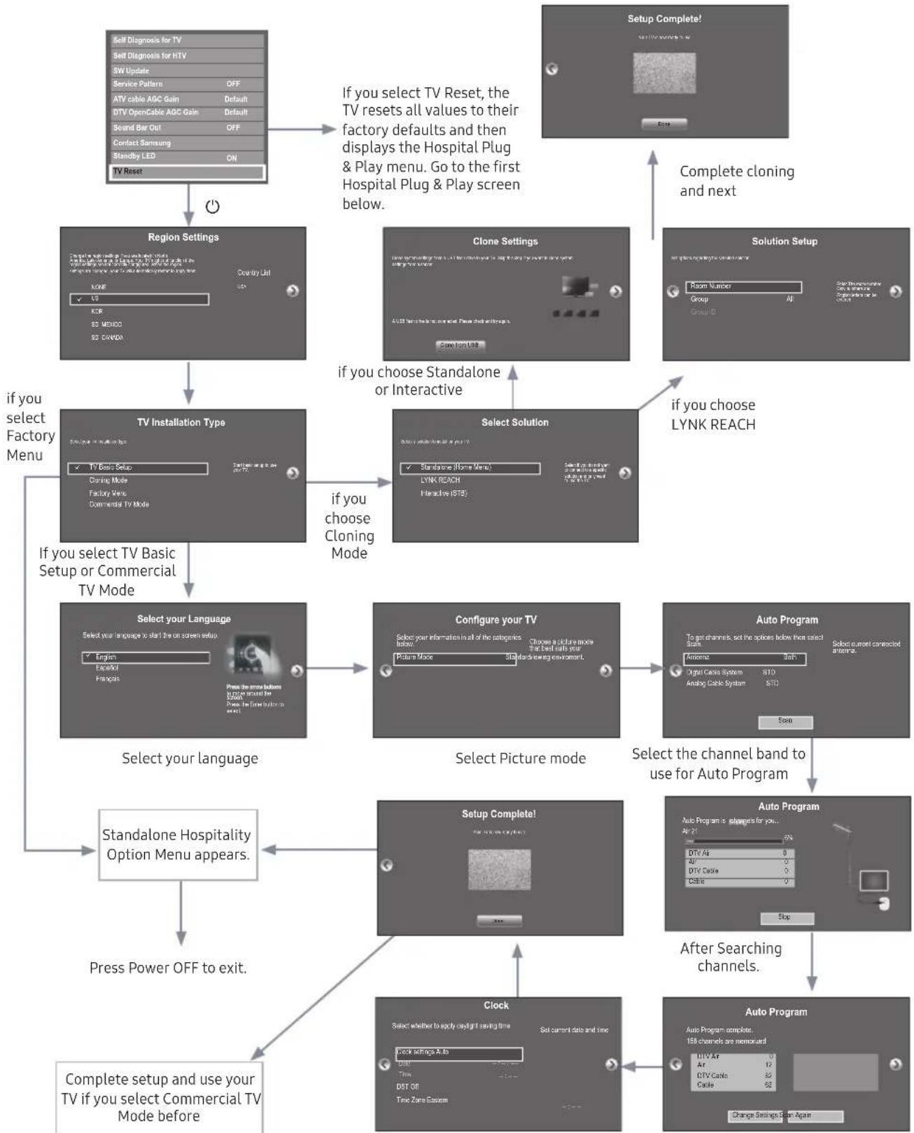
The Hotel Plug & Play function, which automatically performs the Hotel mode selection, Country Setup, Clock Setup, and Picture Mode Setup, runs once, when power is first turned ON. Setup also runs automatically after you have executed a Service Reset.
flowchart
TV setup and configuration flowchart for a hospital plug, covering factory settings, solution selection, channel selection, and auto program setup.Select Clock Mode, DST, and your Time Zone
◆ Region Settings
-Initially highlighted: US
you can select the region you want and next
TV Basic Setup
-Initially highlighted: TV Basic Setup
Start basic setup to use you TV
-If you select the Cloning Mode
Clone system settings from a USB flash drive or erver to your TV.
Make sure that a USB flash drive is connected before you attempt to clone system settings from it.
-If you select Factory Menu
End setup and go directly to the factory you should power off and on to start the TV
-If you select commercial TV Mode
Start basic setup to use your TV in a commercial business
◆ Select Menu Language OSD
- If you select Standalone setup from the "Select Hospital TV Mode" OSD, the "Select Menu Language" OSD appears.
-Initially highlighted: English
- Display time: OSD time out and operation are the same as Samsung's consumer TV models.
-If you press the Enter key, the "Picture Mode" OSD appears.
◆ Configure your TV OSD
-Initially highlighted: Standard.
- The TV displays the Picture Mode OSD where you can choose Dynamic or Standard Picture mode.
◆ Auto Program OSD
- If you press the Enter key, the TV automatically searches for channels.
- After the automatically searches for channels complete, press the next button to continue.
◆ Set Clock Mode, DST(Daylight saving time), and TimeZone OSD
- Initially highlighted: Clock Mode : Auto, DST : Off, TimeZone : Eastern
- If the TV will be tuned to digital broadcast channels, and these channels transmit date and time information, set the Clock Mode to Auto. The TV will set the date and time automatically.
- If the TV will not be tuned to digital broadcast channels, set the Clock Mode to Manual, and then set the date and time on the TV manually.
- Set DST On or Off to apply or not apply daylight saving time to the TV.
-Select your time zone on the map appears.
Samsung may offer upgrades to the TV's SW in the future. Please contact the Samsung Hospitality Hot line at the last page to receive information about downloading upgrades and using a USB drive to update the SW by connecting the USB drive containing the upgrade to the USB port located on the TV.
When the software is upgraded, video and audio settings you have made will return to their default (factory) settings. We recommend you clone the hotel settings so that you can easily reset them after the upgrade.
To upgrade the TV's software, follow these steps:
- Insert a USB drive containing the SW upgrade into the USB port on the side of the TV.
- Press the MENU button to display the menu.
Press the ▲ or ▼ button to select Support, and then press the ENTER button.
- Press the ▲ or ▼ button to select SW Upgrade, and then press the ENTER← button.
The message "Scanning for USB. This may take more than 1min." is displayed.
- The message "Upgrade version XXXX to version XXXX? The system will be reset after upgrade." is displayed. Press the ◀ or ▶ to select OK, and then press the ENTER button.
Please be careful to not disconnect the power or remove the USB drive while upgrades are being applied. The TV will turn off and turn on automatically after completing the SW upgrade. Please check the SW version after the upgrades are complete.
Sound Bar
• Samsung Sound-Bars and Hospitality TVs in 2016
- Samsung Sound-Bars and hospitality TVs support the ARC feature in HDMI 1.4. If you connect a compatible Samsung Sound-Bar to a compatible Samsung hospitality TV using a single HDMI cable, guests can listen to the TV's sound through the Sound-Bar.
- The item of Sound bar Out in Hospitality Option Menu makes you control to where the TV sound is outputted when the TV is turned on.
- If Sound bar Out is On, the TV sound is automatically outputted in the Sound Bar device only whenever TV is turned on.
- If Sound bar Out is Off, the TV sound is automatically outputted in the TV speaker only whenever TV is turned on.
-Models supporting the ARC function are listed below:
• Sound-Bars: HW-E350/E450/E550
HW-F350/F355/FM35/F450/FM45/FM45C/F550/F551/FM55/FM55C/F750/F751
- Setting the Sound-Bars to Hotel Mode
- Set the following Hotel menu options:
-Hotel option > External Device > Sound Bar Out = On.
-Hotel option > Power On > Power On Volume = User Defined.
- Hotel option > Power On > Power On Volume Num > Set greater than 0.
-Hotel option > Power On > Max Volume > Set greater than 0.
- Connect an HDMI cable from the HDMI OUT jack on the back of the Sound-Bar to the HDMI3 port (supporting ARC) on the hospitality TV.
- After the Sound-Bar is connected to the hospitality TV, when the TV turns on, the Sound-Bar automatically detects the TV, and then automatically switches to Hotel Mode.
Sound Bar Hotel mode functional characteristics:
• Power On/Off is synchronized with the TV
• HDMI_CEC defaults set to On
• Functions through the "HDMI OUT" port only
- Disables the "Input mode" key on the VFD to prevent unexpected audio-source changes.
- Acquires adjustable Power On and Max Volume settings from the TV's Hotel option menu. The Sound-Bar's Power On Volume and Max Volume values, however, are 12 of the Power On Volume and Max Volume settings in the TV's Hotel option menu. Example: If the TV's Power On Volume=20 and Max Volume=90, then the Sound Bar's Power On Volume=10 and Max Volume=45.
Channel Bank Editor (Smoovie TV Only)
The Channel Bank Editor in conjunction with the SMOOVIE remote lets you control the channels guests have access to. The Channel Bank Editor provides three Banks of channels and lets you select which channels will be available from each bank. SMOOVIE remotes have instalable Bank Cards which correspond to the channel banks in the Channel Bank Editor. The remotes only allow access to channels in the channel bank that correspond to the installed card. Consequently, the channels a guest can access depend on the Bank Card installed in their SMOOVIE remote.
Setting the Channel Bank Editor under Stand-alone Mode
- Press MUTE + 1 + 1 + 9 + ENTER on the remote to enter the Hotel Standalone menu.
- Go to SI vendor, and then select: "Smoovie"
- Find the new menu option, "Channel".
- Enter the "Channel Bank Editor".
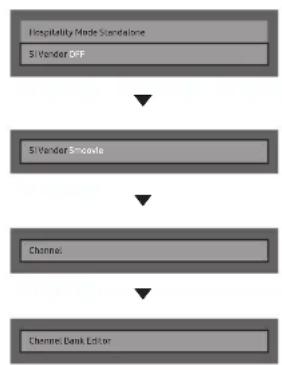
flowchart
graph TD
    A[" Hospitality Mode Standalone\n5-Wonder OFF "] --> B[" 5-Wonder Smoothie "]
    B --> C[" Channel "]
    C --> D[" Channel, Bank Editor "]
- Edit the Channel Bank. An example is below.
a. Bank1 (Free channel): Select the channels that will be accessible when a remote doesn't have a card.
b. Bank2 (Family Card - Green): Select the channels that will be accessible when a remote has a GREEN CARD.
c. Bank3 (Adult Card - Red): Select the channels that will be accessible when a remote has a RED CARD.
Information About SMOOVIE Remote Controls
| Registered | Bank1 (0) | Bank2 (0) | Bank3 (0) | |
| 3 | — (Air) | |||
| 4 | — (Air) | |||
| 6 | — (Air) | |||
| 9-1 | — (Air) | |||
| 11 | — (Air) | |||
| 13 | — (Air) | |||
| 14 | — (Air) | |||
| 15 | — (Air) | |||
| 28 | — (Air) | |||
| 63-1 | SY5000 | |||
- If you select SMOOVIE as the SI vendor, you should also use SMOOVIE remotes in your facility.
• Guests with remotes that do not have a card can only view channels from Bank 1.
• Guests using the Numeric keys on the remote to change channels can only view channels from Bank1.
• Guests with remotes that have Green or Red cards must use the channel up/down keys to change channels.
• Guests can only see channels from the Bank1 channel list In the Channel Guide or the Channel List.
Smoovie Set Up Sequence
| Step | Smoovie TV Setup (Air/ Cable) | |
| Only Air or Cable used Only Air or Cable used | ||
| If the TV starts with Hotel Plug&Play If Hotel Plug&Play already done | ||
| 1 | Do a complete P&P (including Air or Cable auto tune) | Enter the Hotel menu |
| 2 After P&P, the TV displays the Hotel menu | Select the channel type- ATV or ADTV for Air- CATV or CDTV for cable | |
| 3 | Select the channel type- ATV or ADTV for Air- CATV or CDTV for cable | Select Smoovie TV in the Hotel menu |
| 4 Select Smoovie TV in the Hotel menu Select Channel Setup | ||
| 5 | Select Channel Setup(Can be skipped) | Select "Air" or "Cable" to auto tune |
| 6 | Select "Air" or "Cable" to auto tune. (Can be skipped,) | Set up channels in the CH Bank Editor |
| 7 Set up channels in the CH Bank Editor After power off & on, guests can use the TV | ||
| 8 After power off & on, guests can use the TV | ||
| 9 | ||
| 10 | ||
Channel Editor
The Channel Editor lets you edit the channels stored in the TV's memory. Using Channel Editor you can:
- Change the channel numbers and names, and sort the channels in your desired channel number order.
- Apply the video mute to channels you select. The video mute blanks out the video from a channel and outputs only the sound while displaying a speaker icon on the screen.
The Channel Editor also lets you view information about each channel easily, without your having to display each channel directly.
General Steps for Using the Channel Editor in Stand-alone Mode
| Step Broad Outline | |
| 1 Run 'Channel' in the Hotel Option Menu. | |
| 2 Enter 'Channel Editor' in the Hotel Option Menu. | |
| 3 On a piece of paper, compile a list of channels you want to have, arranged in the order you want. | |
| 4 | Rearrange channels and edit channel names with the TOOLS Button based on the list you compiled. |
| 5 | Press the EXIT or RETURN Button to exit. |
The picture below shows a sample Channel Editor screen.
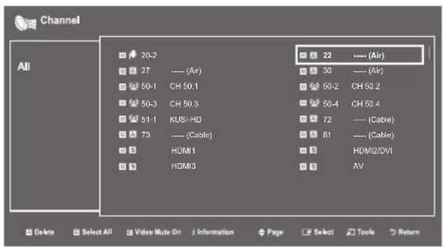
• A Indicates an analog channel.
• Channels without an A are digital channels.
If Dynamic SI in the Hospitality Option Menu is On, Channel Editor will display no digital channels. You must set Dynamic SI to Off before you can edit digital channels in Channel Editor.
- The guide at the bottom of the Channel Editor menu displays the remote buttons you need to press to apply Channel Editor functions.
① Using the remote's up or down arrow key, highlight the channel that you want to edit.
- To edit more than one channel, move the highlight to a channel, and then press the ENTER key. A check will appear in the check box next to the channel. Repeat for each channel you want to edit.
② To delete the channel or channels you selected from the channel list, press the red button on the remote.
- To delete two or more channels simultaneously, select multiple channels in Step 1, and then press the red button on the remote.
If you want to delete the scrambled channels, you should run the process below Hotel option > Channel > Channel Setup > Channel Settings > Clear Scrambled Channel.
③ Press the green button on the remote to select all channels.
4 To apply the video mute, press the yellow button on the remote.
- To apply the video mute to two or more channels simultaneously, select multiple channels in Step 1, and then press the yellow button on the remote.
5 To view information about a channel, press the INFO button on the remote.
6 Press the TOOLS button on the remote to rename a channel or change the channel number.
Channel Editor Functions and Remote Button
A Red (Delete): Deletes a channel from the channel list.
B Green (Select All): Selects all channels at once.
C Yellow (Video Mute On/Off): You can set the Video Mute On/Off.
(Page): Moves to next or previous page.
i (Information): Display details of the selected channel.
(Tools): Displays the option menu.
(D) (Return): Returns to the previous step or exits.
When you press the TOOLS button, the following menu is available.
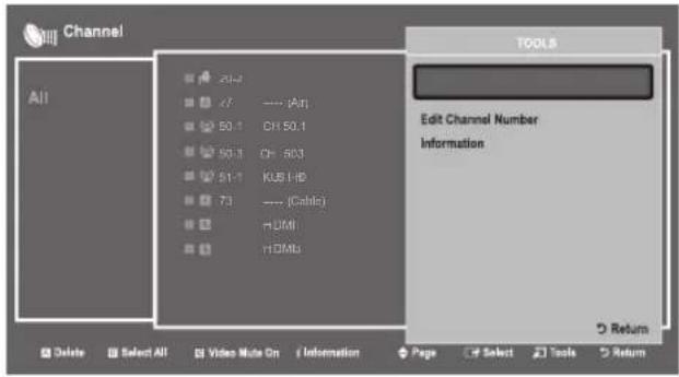
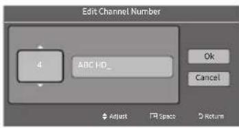
- Edit Channel Number
Use Edit Channel Number to change the channel number of a channel you select.
To change a channel number, follow these steps:
- Select a channel on the Channel Edit screen.
- Press the TOOLS button on your remote.
- Select Edit Channel Number in the Tools menu.
- Use the up or down arrow keys to change the channel number.
- Select OK when done, and then press the ENTER← button.
When you change the channel number, the channel information is not updated automatically.
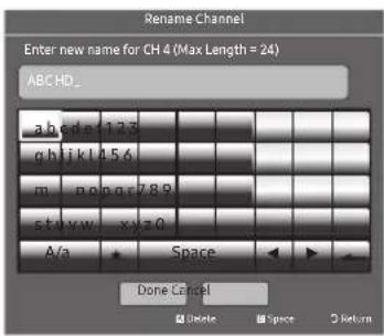
- Rename Channel
Use Rename Channel to change the name of a channel you select.
To change the name of a channel, follow these steps:
- Select a channel on the Channel Edit screen.
- Press the TOOLS button on your remote.
- Select Rename Channel in the Tools menu.
- Use the on-screen keyboard that appears to enter the new name for the channel. Use the arrow buttons on your remote to select a letter or number, and then press Enter. Repeat for each letter or number you want to select.
- When finished, select Done on the bottom of the screen, and then press the ENTER button.
- Information
Use Information to view information about a channel you select.
To view information about a channel, follow these steps:
- Select a channel on the Channel Edit screen.
- Press the TOOLS button on your remote.
- Select Information in the Tools menu.
- Select OK, and then press the ENTER button to close the Information screen.

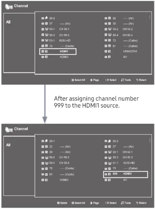
The external sources of this TV are displayed in the last page of the Channel Editor menu as shown in the example below. In the example, there are four external sources connected to the TV, HDMI1, HDMI2(DVI), HDMI3 and AV.
- You can assign a new analog channel to an external source by selecting the source on the last page, pressing the TOOLS button, selecting Edit Channel Number, and then using the up or down arrow button on the remote to select the channel number of the analog channel.
- If you tune to a channel after assigning the channel to an external source, you can enter the external source without opening the TV source menu.
flowchart
graph TD
    A["Channel"] --> B["All"]
    B --> C["20-2"]
    B --> D["27"]
    B --> E["50-1"]
    B --> F["50-3"]
    B --> G["51-1"]
    B --> H["73"]
    C --> I["(Air)"]
    D --> J["(Air)"]
    E --> K["(Air)"]
    F --> L["(Air)"]
    G --> M["(Air)"]
    H --> N["(Cable)"]
    I --> O["22"]
    I --> P["30"]
    I --> Q["60-2"]
    I --> R["50-4"]
    I --> S["72"]
    I --> T["(Cable)"]
    I --> U["81"]
    I --> V["HDMI2/DVI"]
    I --> W["AV"]
    X["After assigning channel number 999 to the HDMI1 source."] --> Y["Channel"]
    Y --> Z["20-1"]
    Y --> AA["22"]
    Y --> AB["30"]
    Y --> AC["50-2"]
    Y --> AD["50-4"]
    Y --> AE["72"]
    Y --> AF["81"]
    Y --> AG["(Cable)"]
    Y --> AH["HDMI3"]
    Z --> AI["(Air)"]
    AA --> AJ["(Air)"]
    AB --> AK["(Air)"]
    AC --> AL["(Air)"]
    AD --> AM["(Air)"]
    AE --> AN["(Air)"]
    AF --> AO["(Air)"]
    AG --> AP["(Cable)"]
    AH --> AQ["HDMI1"]
    AI --> AR["(Air)"]
    AJ --> AS["(Air)"]
    AK --> AT["(Air)"]
    AL --> AU["(Air)"]
    AM --> AV["(Air)"]
    AN --> AW["(Air)"]
    AO --> AX["(Air)"]
    AP --> AY["(Air)"]
    AQ --> AZ["(Air)"]
    AR --> BA["(Air)"]
Installing the Wall Mount

Wall or Ceiling Mounting
If you mount this product on a wall, it should be mounted only as recommended by the manufacturer. Unless it is correctly mounted, the product may slide or fall, causing serious injury to a child or adult, and serious damage to the product.
Preparing before installing Wall-Mount
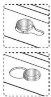
To install a wall-mount from another manufacturer, use the Holder-Ring.
The product shape may differ depending on the model.
Before installing any other wall mounting kit, assemble the wall mount adapter provided separately with the TV.
Installing the Wall Mount Kit
The wall mount kit (sold separately) lets you mount the TV on the wall. For detailed information about installing the wall mount, see the instructions provided with the wall mount. Contact a technician for assistance when installing the wall mount bracket. Samsung Electronics is not responsible for any damage to the product or injury to yourself or others if you elect to install the wall mount on your own.
To order the wall mount, contact Samsung Customer Care at 1-800-SAMSUNG (1-800-726-7864).
natural_image
Technical diagram of a mechanical assembly with labeled components and an inset view (no text or symbols present)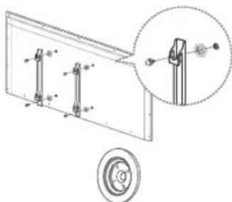
natural_image
Technical diagram of a mechanical assembly with mounting brackets and a close-up inset showing a pin alignment (no text or symbols)Wall mount Adapter (Depending on the Model)
Wall Mount Kit Specifications (VESA)
The wall mount kit is not supplied, but sold separately.
Install your wall mount on a solid wall perpendicular to the floor. When attaching to building materials other than plaster board, please contact your nearest dealer. If you install the wall mount on a ceiling or slanted wall, TV may fall and cause severe personal injury.
NOTE
- Standard dimensions for wall mount kits are shown in the table below.
- Samsung wall mount kits contain a detailed installation manual. All parts necessary for assembly are provided.
- Do not use screws that do not comply with the VESA standard screw specifications.
- Do not use screws that are longer than the standard dimension or do not comply with the VESA standard screw specifications. Screws that are too long may cause damage to the inside of the TV set.
- For wall mounts that do not comply with the VESA standard screw specifications, the length of the screws may differ depending on the wall mount specifications.
- Do not fasten the screws too firmly. This may damage the product or cause the product to fall, leading to personal injury. Samsung is not liable for these kinds of accidents.
- Samsung is not liable for product damage or personal injury when a non-VESA or non-specified wall mount is used or the consumer fails to follow the product installation instructions.
- Do not mount the TV at more than a 15 degree tilt.
• Always have two people mount the TV onto a wall.
| Product Family | TV size in inches | VESA screw hole specs (A * B) in millimeters | Standard Screw (Length* Pitch in mm) | Quantity |
| LED-TV | 22-24 75 x 75 | M4 | 4 | |
| 28 100 x 100 | ||||
| 32-50 200 x 200 | M8 | |||
| 55-65 400 x 400 | ||||

Do not install your Wall Mount Kit while your TV is turned on. It may result in personal injury due to electric shock.
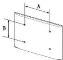
Securing the TV to the Wall

Caution
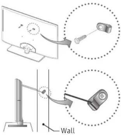
Pulling, pushing, or climbing onto the TV may cause the TV to fall. In particular, ensure that your children do not hang over or destabilize the TV; doing so may cause the TV to tip over, resulting in serious injuries or death. Follow all safety precautions provided on the included Safety Flyer. For added stability, install the anti-fall device for safety purposes, as follows.
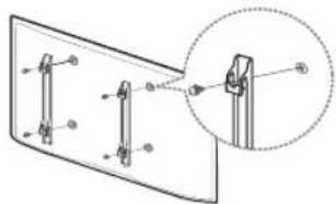
To Avoid the TV from Falling
- Put the screws into the clamps and firmly fasten them onto the wall. Confirm that the screws have been firmly installed onto the wall.
You may need additional material such as an anchor depending on the type of wall.
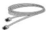
Since the necessary clamps, screws, and string are not supplied, please purchase these additionally.
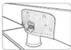
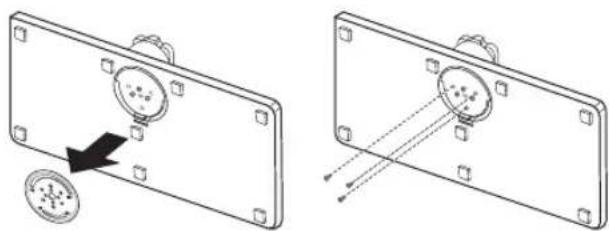
- Remove the screws from the back center of the TV, put the screws into the clamps, and then fasten the screws onto the TV again.
Screws may not be supplied with the product. In this case, please purchase the screws.
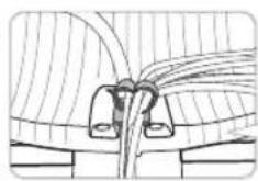
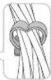
- Connect the clamps fixed onto the TV and the clamps fixed onto the wall with a strong string and then tie the string tightly.
NOTE
• Install the TV near to the wall so that it does not fall backwards.
- It is safe to connect the string so that the clamps fixed on the wall are equal to or lower than the clamps fixed on the TV.
- Untie the string before moving the TV.
- Verify all connections are properly secured. Periodically check connections for any sign of fatigue for failure. If you have any doubt about the security of your connections, contact a professional installer.
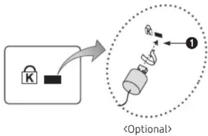
Anti-theft Kensington Lock
The Kensington Lock is a device you can use to physically fix a TV to a location when you use it in a public place. The appearance and locking method may differ from the illustration at right, depending on the manufacturer. Refer to the manual provided with the Kensington Lock for additional information on proper use.
The Kensington Lock is not supplied by Samsung.
Please find the "☑" icon on the rear of the TV. A Kensington slot is beside the "☑" icon.
flowchart
graph TD
    A["Lock"] --> B["Switch"]
    B --> C["Optional Step"]
    C --> D["Step 1"]
    D --> E["Feedback Loop"]
    E --> F["Step 2"]
To lock the product, follow these steps:
- Wrap the Kensington lock cable around a large, stationary object such as desk or chair.
- Slide the end of the cable with the lock attached through the looped end of the Kensington lock cable.
-
Insert the locking device into the Kensington slot on the product ①.
-
Lock the lock.
These are general instructions. For exact instructions, see the User manual supplied with the locking device.
The locking device has to be purchased separately.
The location of the Kensington slot may be different depending on the TV model.
Specifications
| Environmental ConsiderationsOperating TemperatureOperating HumidityStorage TemperatureStorage Humidity | 50°F to 104°F (10°C to 40°C)10% to 80%, non-condensing-4°F to 113°F (-20°C to 45°C)5% to 95%, non-condensing | |
| Model Name | HG32NE460S HG40NE460S | |
| Display Resolution | 1366 x 768 1920 x 1080 | |
| Screen Size(Diagonal) | 32" Class(31.5" measured diagonally) | 40" Class(39.5" measured diagonally) |
| Sound (Output) | 5W x 2 10W x 2 | |
| Dimensions (W x D x H)BodyWith stand | 745.4 x 69.0 x 442.2 mm745.4 x 163.4 x 484.2 mm | 922.7 x 72.0 x 530.7 mm922.7 x 170.3 x 555.1 mm |
| WeightWithout StandWith Stand | 4.0 kg4.4 kg | 6.7 kg6.9 kg |
| Model Name | HG43NE460S HG50NE460S | |
| Display Resolution | 1920 x 1080 | |
| Screen Size(Diagonal) | 43" Class(42.5" measured diagonally) | 50" Class(49.5" measured diagonally) |
| Sound (Output) | 10W x 2 | |
| Dimensions (W x D x H)BodyWith stand | 985.5 x 72.2 x 575.3 mm985.5 x 170.3 x 597.1 mm | 1140.8 x 72.9 x 662.3 mm1140.8 x 187.6 x 684.2 mm |
| WeightWithout StandWith Stand | 77 kg7.9 kg | 10.4 kg10.7 kg |
| Model Name | HG24NE470A HG43NE470S/HG43NE477S | |
| Display Resolution | 1366 x 768 1920 x 1080 | |
| Screen Size(Diagonal) | 24" Class(23.6" measured diagonally) | 43" Class(42.5" measured diagonally) |
| Sound (Output) | 5W x 2 10W x 2 | |
| Dimensions (W x D x H)BodyWith stand | 561.8 x 65.2 x 349.1 mm561.8 x 163.8 x 384.2 mm | 985.5 x 72.2 x 575.3 mm985.5 x 226.5 x 624.2 mm |
| WeightWithout StandWith Stand | 3.9 kg4.1 kg | 77 kg10.7 kg |
| Stand Swivel (Left / Right) | -20° / 60° / 90° | |
| Model Name | HG50NE470S/HG50NE477S HG55NE470B/HG55NE477B | |
| Display Resolution | 1920 x 1080 1920 x 1080 | |
| Screen Size(Diagonal) | 50" Class(49.5" measured diagonally) | 55" Class(54.6" measured diagonally) |
| Sound (Output) | 10W x 2 10W x 2 | |
| Dimensions (W x D x H)BodyWith stand | 1140.8 x 72.9 x 662.3 mm1140.8 x 226.5 x 713.9 mm | 1231.6 x 68.6 x 708.6 mm1231.6 x 226.4 x 763.5 mm |
| WeightWithout StandWith Stand | 10.4 kg13.3 kg | 13.6 kg16.5 kg |
| Stand Swivel (Left / Right) | 20° / 60° / 90° | |
| Model Name | HG60NE470E/HG60NE477E HG28NE470 | |
| Display Resolution | 1920 x 1080 1366 x 768 | |
| Screen Size (Diagonal) | 60" Class(60.0" measured diagonally) | 28" Class(27.5" measured diagonally) |
| Sound (Output) | 10W x 2 5W x 2 | |
| Dimensions (W x D x H) | ||
| Body | 1365.0 x 64.4 x 786.4 mm | 643.4 x 62.9 x 396.5 mm |
| With stand | 1365.0 x 355.1 x 859.3 mm | 643.4 x 163.4 x 435.0 mm |
| Weight | ||
| Without Stand | 21.1 kg | 3.8 kg |
| With Stand | 26.1 kg | 4.2 kg |
| Stand Swivel (Left / Right) | 20° / 60° / 90° | - |
| Model Name | HG32NE470S/HG32NE477S HG40NE470S/HG40NE477S | |
| Display Resolution | 1366 x 768 1920 x 1080 | |
| Screen Size (Diagonal) | 32" Class(31.5" measured diagonally) | 40" Class(39.5" measured diagonally) |
| Sound (Output) | 5W x 2 10W x 2 | |
| Dimensions (W x D x H) | ||
| Body | 745.4 x 69.0 x 442.2 mm | 922.7 x 72.0 x 530.7 mm |
| With stand | 745.4 x 192.6 x 484.7 mm | 922.7 x 226.5 x 582.3 mm |
| Weight | ||
| Without Stand | 4.0 kg | 6.8 kg |
| With Stand | 5.6 kg | 9.7 kg |
| Stand Swivel (Left / Right) | 20° / 60° / 90° | |
| Model Name | HG28NE473 HG32NE473 | |
| Display Resolution | 1366 x 768 1366 x 768 | |
| Screen Size (Diagonal) | 28" Class(27.5" measured diagonally) | 32" Class(31.5" measured diagonally) |
| Sound (Output) | 5W x 2 5W x 2 | |
| Dimensions (W x D x H) | ||
| Body 643.4 x 62.9 x 396.5 mm 745.4 x 69.0 x 442.2 mm | ||
| Weight | 3.8 kg 4.1 kg | |
| Model Name | HG22NE478 HG32NE478B | |
| Display Resolution | 1920 x 1080 | |
| Screen Size (Diagonal) | 22" Class(21.5" measured diagonally) | 32" Class(31.5" measured diagonally) |
| Sound (Output) | 3W x 2 10W x 2 | |
| Dimensions (W x D x H) | ||
| Body | 506.9 x 317.1 x 46.8 mm | 721.4 x 66.8 x 424.8 mm |
| With stand | 506.9 x 355.2 x 151.8 mm | 721.4 x 192.6 x 466.3 mm |
| Weight | ||
| Without Stand | 3.1 kg | 4.8 kg |
| With Stand | 3.3 kg | 6.4 kg |
| Stand Swivel (Left / Right) | 20° / 60° / 90° | |
| Model Name | HG40NE478S HG43NE478S | |
| Display Resolution | 1920 x 1080 | |
| Screen Size (Diagonal) | 40" Class(39.5" measured diagonally) | 43" Class(42.5" measured diagonally) |
| Sound (Output) | 10W x 2 | |
| Dimensions (W x D x H) | ||
| Body | 922.7 x 72.0 x 530.7 mm | 985.5 x 72.2 x 575.3 mm |
| With stand | 922.7 x 226.5 x 582.3 mm | 985.5 x 226.5 x 624.2 mm |
| Weight | ||
| Without Stand | 6.8 kg | 7.7 kg |
| With Stand | 9.7 kg | 10.7 kg |
| Stand Swivel (Left / Right) | 20° / 60° / 90° | |
| Model Name | HG50NE478S HG55NE478B | |
| Display Resolution | 1920 x 1080 | |
| Screen Size (Diagonal) | 50" Class(49.5" measured diagonally) | 55" Class(54.6" measured diagonally) |
| Sound (Output) | 10W x 2 | |
| Dimensions (W x D x H) | ||
| Body | 1140.8 x 72.9 x 662.3 mm | 1231.6 x 68.6 x 708.6 mm |
| With stand | 1140.8 x 226.5 x 713.9 mm | 1231.6 x 226.4 x 763.5 mm |
| Weight | ||
| Without Stand | 10.4 kg | 13.60 kg |
| With Stand | 13.3 kg | 16.50 kg |
| Stand Swivel (Left / Right) | 20° / 60° / 90° | |
| Model Name | HG65NE478E | |
| Display Resolution | 1920 x 1080 | |
| Screen Size (Diagonal) | 65" Class(64.5" measured diagonally) | |
| Sound (Output) | 10W x 2 | |
| Dimensions (W x D x H) | ||
| Body | 1454.5 x 70.9 x 835.4 mm | |
| With stand | 1454.5 x 355.1 x 909.7 mm | |
| Weight | ||
| Without Stand | 25.9 kg | |
| With Stand | 30.9 kg | |
| Stand Swivel (Left / Right) | 20° / 60° / 90° | |
Design and specifications are subject to change without prior notice.
This device is a Class B digital apparatus.
| File Extention Container Video | Codec Resolution Frame rate(fps) Bit rate(Mbps) Audio Codec | |||||
| *.avi / *.mkv*.asf / *.wmv*.mp4 / *.3gp*.vro / *.mpg*.mpeg / *.ts*.tp / *.trp*.mov / *.flv*.vob / *.svi*.divx | AVIMKVASFMP43GPVROVOBPSTS | DivX 3.11/4.x/5.x/6.x | 1920 x 1080 | 6~30 | 30 | Dolby Digital LPCMADPCM(IMA, MS)AACHE-AACWMDolby Digital PlusMPEG (MP3)DTS (Core)G.711(A-Law, μ-Law) |
| MPEG4 SP/ASP | ||||||
| H.264 BP/MP/HP | ||||||
| Motion JPEG 640 x 480 8 | ||||||
| Window Media Video v9 | 1920 x 1080 30 | |||||
| MPEG2 | ||||||
| MPEG1 | ||||||
Other Restrictions
• Video content will not play, or not play correctly, if there is an error in the content or the container.
- Sound or video may not work if the contents have a standard bit rate/frame rate above the compatible Frame/sec listed in the table.
- If the Index Table is in error, the Seek (Jump) function is not supported.
- Some USB/digital camera devices may not be compatible with the player.
- The menu can be displayed late if the video is over 10Mbps(bit rate).
| Video decoder | Audio decoder |
| Supports up to H.264, Level 4.1 (FMO/ASO/RS are not supported.)frame rate :Below 1280 x 720: 60 frame maxAbove 1280 x 720: 30 frame maxVC1 AP L4 is not supported.GMC is not supported. | WMA 10 Pro supports up to 5.1 channel and M2 profile.WMA lossless audio is not supported.Vorbis supports up to 2ch.Dolby Digital Plus supports up to 5.1 channel. |
Supported Subtitle Formats
- External
| Name File extension | |
| MPEG-4 timed text .ttxt | |
| SAMI .smi | |
| SubRip .srt | |
| SubViewer .sub | |
| Micro DVD .sub or .txt | |
| SubStation Alpha .ssa | |
| Advanced SubStation Alpha .ass | |
| Powerdivx .psb |
Supported Photo Formats
| File Extension Type | Resolution | |
| *.jpg | JPEG 15360 X | 8640 |
| *.jpeg | ||
| *.bmp BMP | 4096 X 4096 | |
| *.mpo | MPO | 15360 X 8640 |
- Internal
| Name | Container | Format |
| Xsub | AVI | Picture Format |
| SubStation Alpha | MKV | Text Format |
| Advanced SubStation Alpha | MKV | Text Format |
| SubRip | MKV | Text Format |
| MPEG-4 timed text | MP4 | Text Format |
Supported Music Formats
| File Extension | Type | Codec | Remark |
| *.mp3 | MPEG | MPEG1 Audio Layer 3 | |
| *.m4a *.mpa *.aac | MPEG4 | AAC | |
| *.flac | FLAC | FLAC | Can support up to 2channel |
| *.ogg | OGG | Vorbis | Can support up to 2channel |
| *.wma | WMA | WMA | WMA 10 Pro supports up to 5.1 channel and M2 profile. (WMA lossless audio is not supported.) |
| *.wav | wav | wav | |
| *.mid *.midi | midi | midi | Can not support seeking |
Dimensions
Front view / Side view
HG32NE460
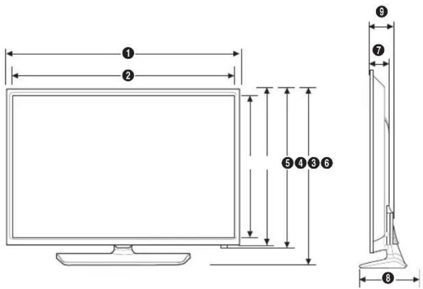
(Unit: mm)
| 1 2 | 3 4 5 6 | 7 8 9 | ||||||
| 745.4 | 699.7 | 394.3 | 433.9 | 442.2 | 484.2 | 57.9 | 163.4 | 69.0 |
HG40NE460/HG43NE460/HG50NE460
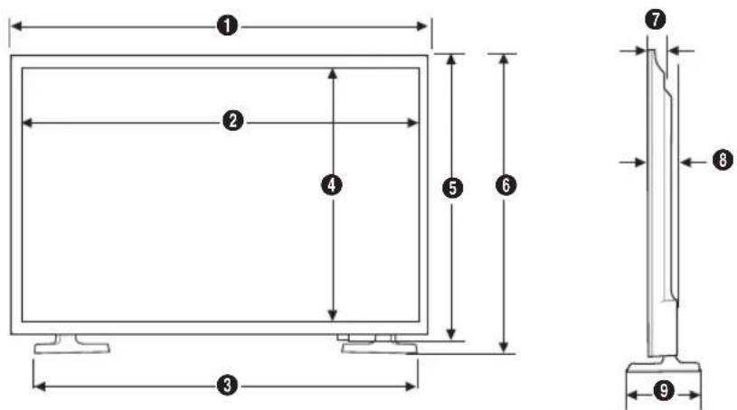
(Unit: mm)
| 1 2 | 3 4 5 | 6 7 8 9 | |||||||
| HG40NE460 | 922.7 | 880.1 | 802.2 | 487.4 | 530.7 | 555.1 | 40.5 | 72.0 | 170.3 |
| HG43NE460 | 985.5 | 942.9 | 872.3 | 531.3 | 575.3 | 597.1 | 40.5 | 72.9 | 170.3 |
| HG50NE460 | 1140.8 | 1097.8 | 1012.5 | 618.4 | 662.3 | 684.2 | 41.6 | 72.9 | 187.6 |
HG28NE473
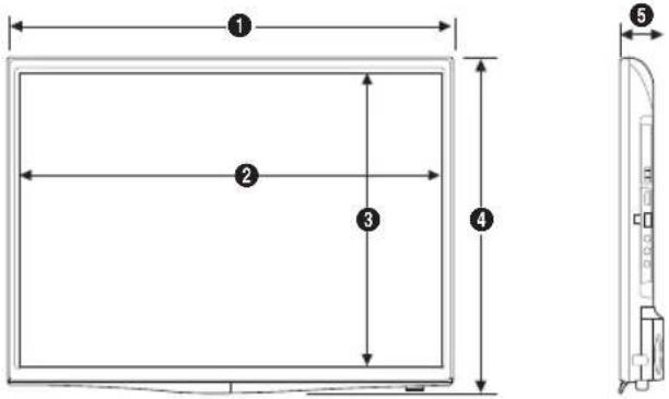
(Unit: mm)
| 1 2 3 4 5 | ||||
| 643.4 | 609.5 | 347.0 | 396.5 | 62.9 |
HG32NE473
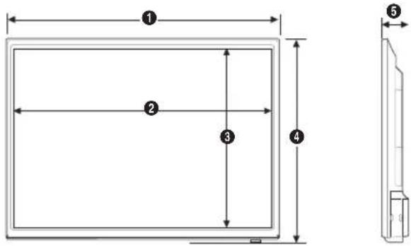
(Unit: mm)
| 1 2 3 4 5 | ||||
| 745.4 | 699.7 | 394.3 | 442.2 | 69.0 |
HG24NE470A
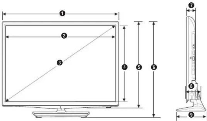
(Unit: mm)
| 1 2 3 4 5 6 | 7 8 9 | |||||||
| 561.8 | 523.3 | 600.0 | 295.2 | 349.1 | 384.2 | 47.9 | 65.2 | 163.8 |
HG28NE470
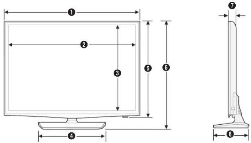
(Unit: mm)
| 1 2 3 4 5 6 7 8 | |||||||
| 643.4 | 609.5 | 347.0 | 311.4 | 396.5 | 435.0 | 62.9 | 163.4 |
HG32NE470S/HG32NE477S/HG40NE470S/HG40NE477S/HG40NE478S/HG43NE470S/HG43NE477S/HG43NE478S/HG50NE470S/HG50NE477S/HG50NE478S
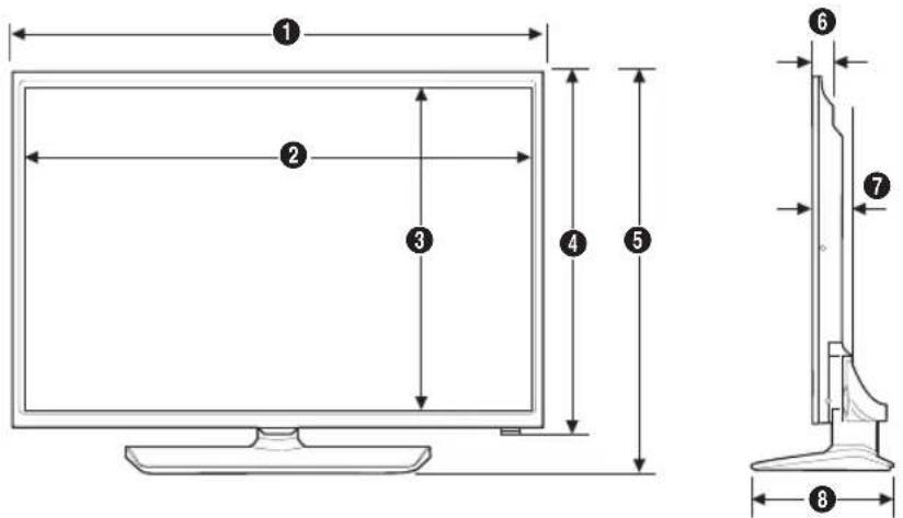
(Unit: mm)
| 1 2 3 4 5 6 7 8 | ||||||||
| HG32NE470SHG32NE477S | 745.4 | 699.7 | 394.3 | 442.2 | 484.7 | 57.9 | 69.0 | 192.6 |
| HG40NE470SHG40NE477SHG40NE478S | 922.7 | 880.1 | 487.4 | 530.7 | 582.3 | 40.5 | 72.0 | 226.5 |
| HG43NE470SHG43NE477SHG43NE478S | 985.5 | 942.9 | 531.3 | 575.3 | 624.2 | 40.5 | 72.2 | 226.5 |
| HG50NE470SHG50NE477SHG50NE478S | 1140.8 | 1097.8 | 618.4 | 662.3 | 713.9 | 41.6 | 72.9 | 226.5 |
HG55NE470/HG55NE477/HG55NE478
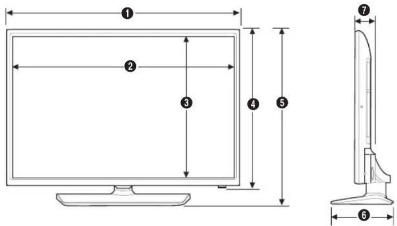
(Unit: mm)
| 1 2 3 | 4 5 6 7 | |||||
| 1231.6 1211.6 | 682.3 708.6 763 | 5 226.4 | 68.6 |
HG22NE478
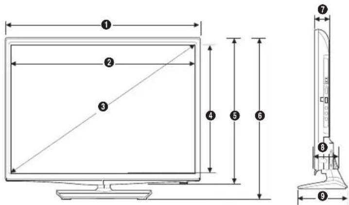
(Unit: mm)
| 1 2 | 3 4 5 6 | 7 8 9 | ||||||
| 506.9 | 477.5 | 547.2 | 269.0 | 317.1 | 355.2 | 46.8 | 66.2 | 151.8 |
HG32NE478B
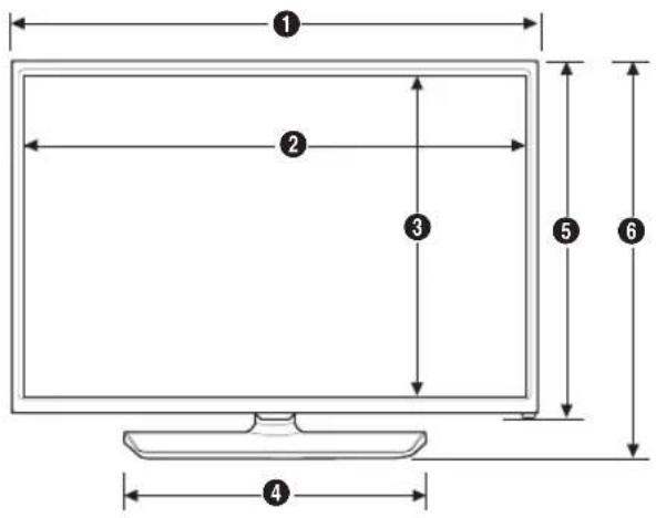
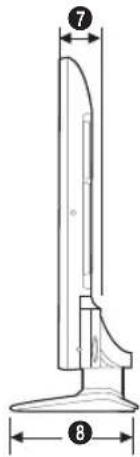
(Unit: mm)
| 1 2 3 4 5 6 7 8 | |||||||
| 721.4 | 700.4 | 394.4 | 451.3 | 424.8 | 466.3 | 66.8 | 192.6 |
HG60NE470/HG60NE477
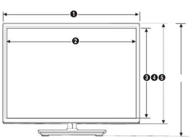
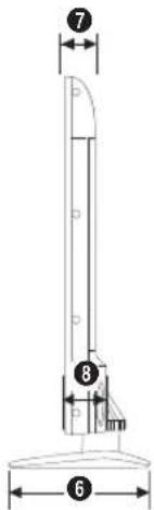
(Unit: mm)
| 1 2 3 4 5 6 7 8 | |||||||
| 1365.0 | 1331.0 | 749.6 | 786.4 | 859.3 | 355.1 | 51.6 | 64.4 |
HG65NE478
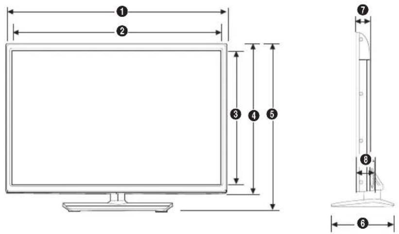
(Unit: mm)
| 1 2 3 4 5 6 7 8 | |||||||
| 1454.5 | 1430.5 | 805.5 | 835.4 | 909.7 | 355.1 | 56.2 | 70.9 |
Rear view
HG22NE478
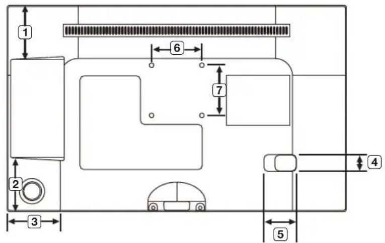
(Unit: mm)
| 1 2 3 | 4 5 6 7 | |||||
| 81.2 81.5 80.0 26.0 50.0 75.0 75.0 | ||||||
HG24NE470
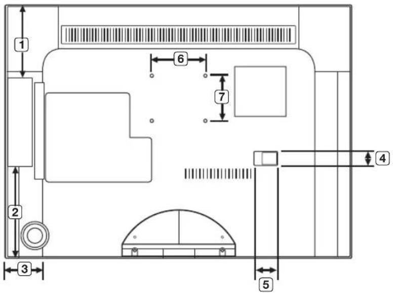
(Unit: mm)
| 1 2 3 | 4 5 6 7 | |||||
| 94.8 | 96.2 | 81.7 | 22.8 | 30.8 | 75.0 | 75.0 |
HG28NE470/HG28NE473
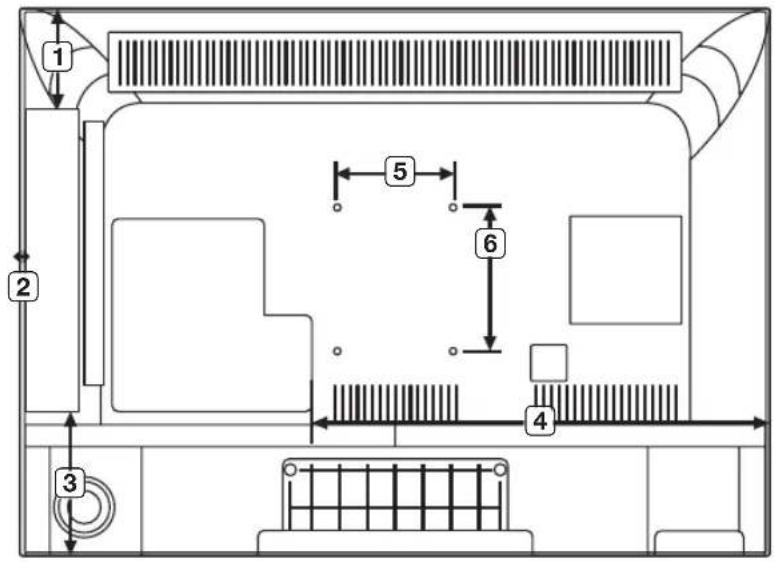
(Unit: mm)
| 1 2 3 | 4 5 6 | |||||
| HG28NE470HG28NE473 | 69.5 5.1 100. | 0 390.8 100.0 100.0 |
HG32NE478
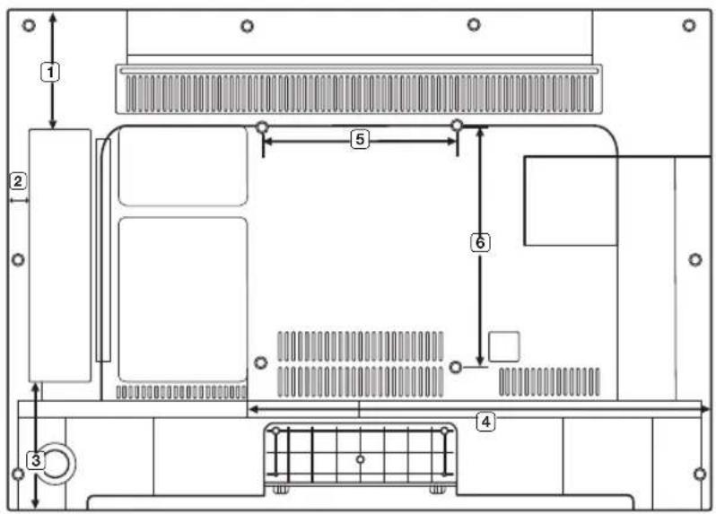
(Unit: mm)
| 1 2 3 | 4 5 6 | ||||
| 98.5 20.8 10 | 9.8 474.7 200.0 200.0 |
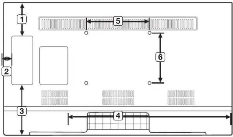
(Unit: mm)
| 1 2 3 | 4 5 6 | |||||
| HG55NE470HG55NE477HG55NE478 | 225.6 | 91.9 | 234.5 | 109.5 | 400.0 | 400.0 |
HG40/43/50NE4xS
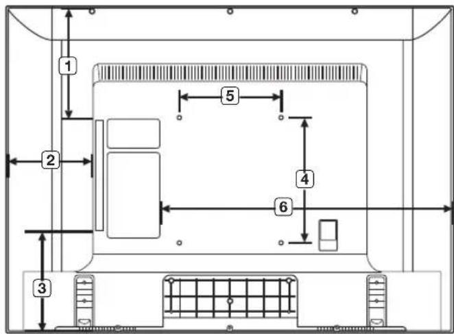
(unit: mm)
| 1 2 3 | 4 5 6 | |||||
| HG40NE460SHG40NE470SHG40NE477SHG40NE478S | 144.6 151 | 3 187.8 200.0 200.0 623.5 | ||||
| HG43NE460SHG43NE470SHG43NE477SHG43NE478S | 182.7 151.6 | 195.4 200.0 200.0 661.0 | ||||
| HG50NE460SHG50NE470SHG50NE477SHG50NE478S | 294.5 | 224.2 | 169.7 | 200.0 | 200.0 | 759.1 |
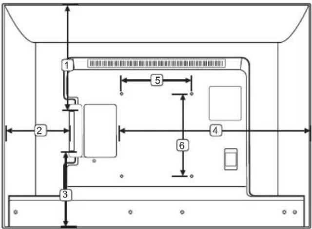
(unit: mm)
| 1 2 3 | 4 5 6 | |||||
| HG32NE460SHG32NE470SHG32NE477S | 144.6 | 133.3 | 163.0 | 459.5 | 200.0 | 200.0 |
HG60NE470/HG60NE477
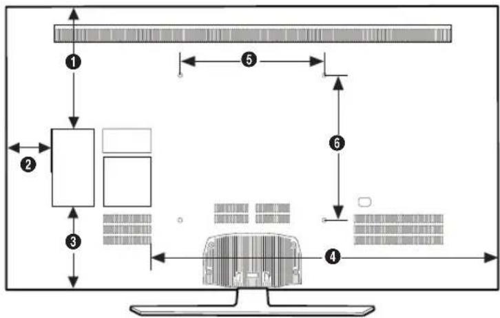
flowchart
graph TD
    A["1"] --> B["2"]
    B --> C["3"]
    C --> D["4"]
    D --> E["5"]
    E --> F["6"]
    F --> G["7"]
    G --> H["8"]
(Unit: mm)
| 1 2 3 | 4 5 6 | ||||
| 339.6 | 125.9 | 231.4 | 964.1 | 400.0 | 400.0 |
HG65NE478
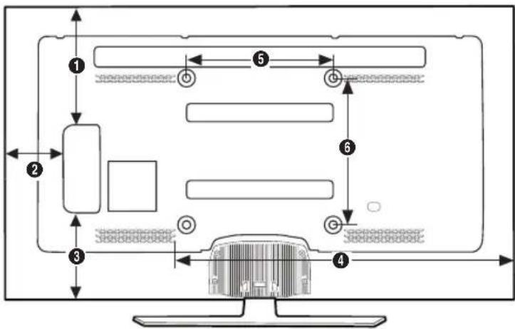
flowchart
graph TD
    A["1"] --> B["2"]
    B --> C["3"]
    C --> D["4"]
    D --> E["5"]
    E --> F["6"]
    F --> G["7"]
    G --> H["8"]
    H --> I["9"]
    I --> J["10"]
    style A fill:#f9f,stroke:#333
    style B fill:#ccf,stroke:#333
    style C fill:#cfc,stroke:#333
    style D fill:#fcc,stroke:#333
    style E fill:#ffc,stroke:#333
    style F fill:#cfc,stroke:#333
    style G fill:#fcc,stroke:#333
    style H fill:#cfc,stroke:#333
    style I fill:#fcc,stroke:#333
(Unit: mm)
| 1 2 3 | 4 5 6 | ||||
| 369.1 | 191.0 | 223.5 | 957.0 | 400.0 | 400.0 |
Stand base view
HG24NE470/HG22NE478
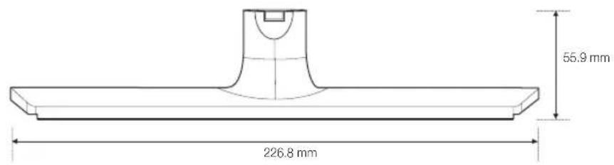
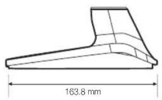
HG28NE470/HG32NE460
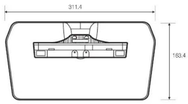

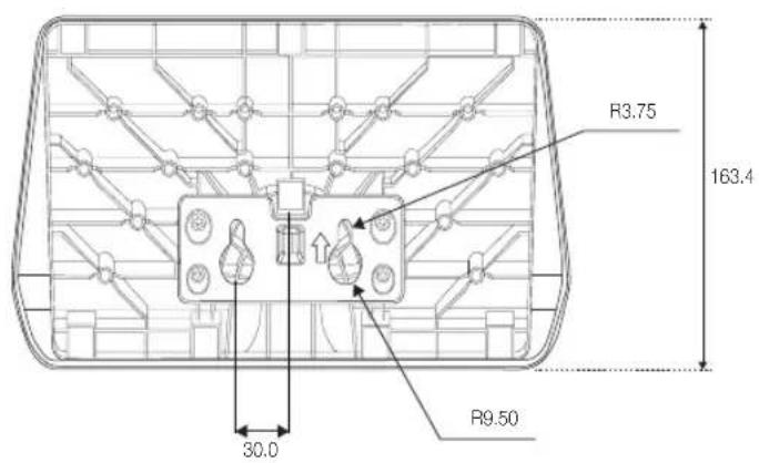
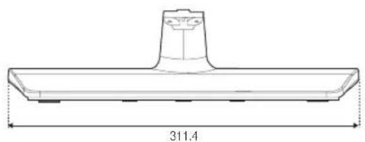
HG40NE460S/HG43NE460S
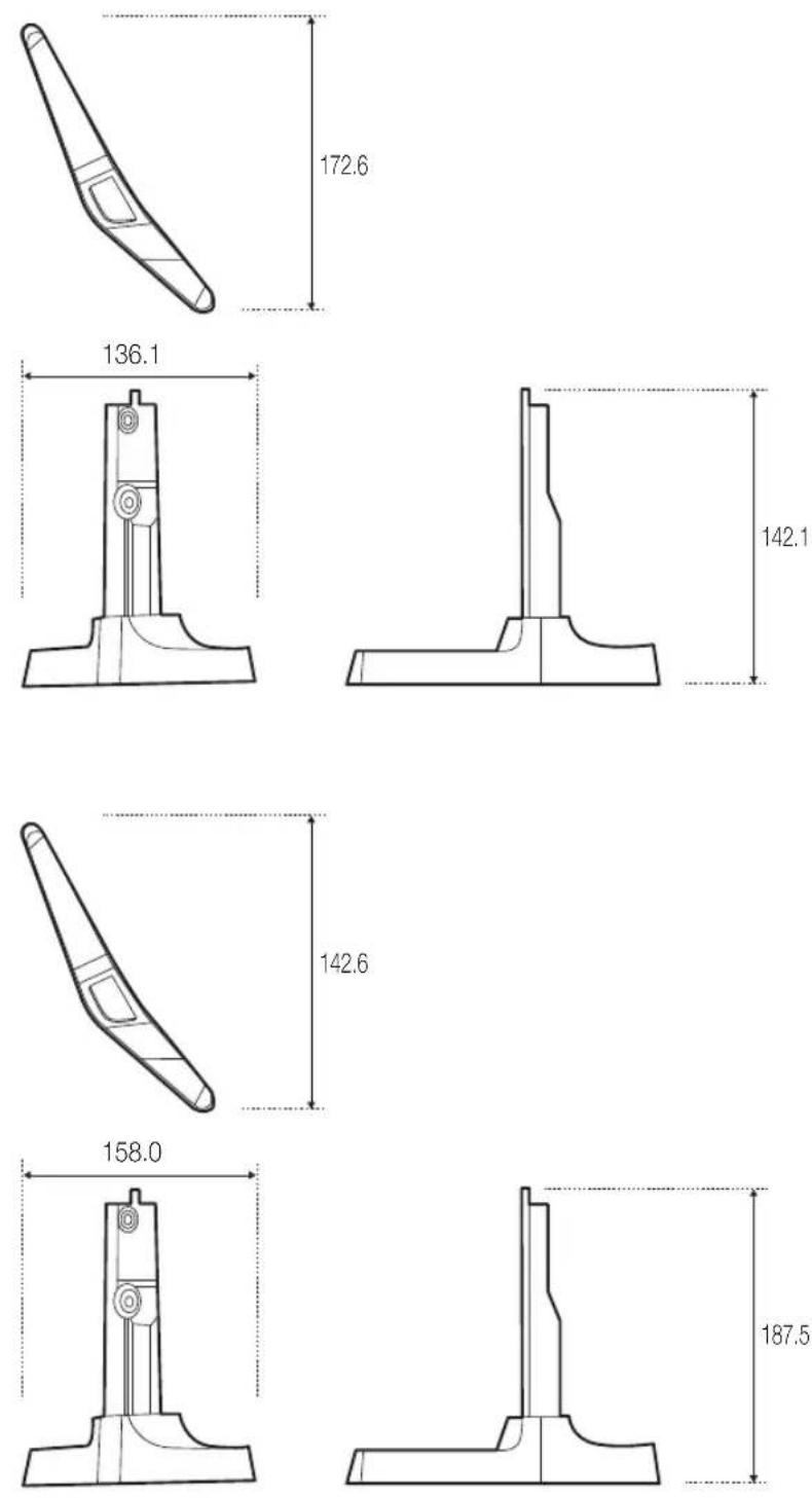
HG50NE460S
HG32NE470/HG32NE477/HG32NE478
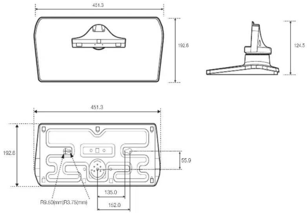
HG40NE470/HG40NE477/HG40NE478/HG43NE470/HG43NE477/HG43NE478/HG50NE470/HG50NE477/HG50NE478/HG55NE470/HG55NE477/HG55NE478
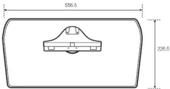
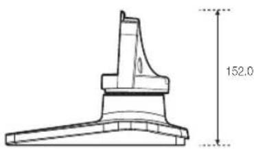
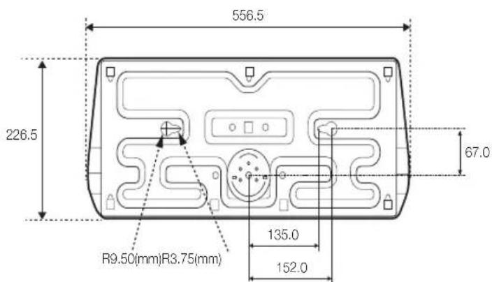
HG60NE470/HG60NE477/HG65NE478
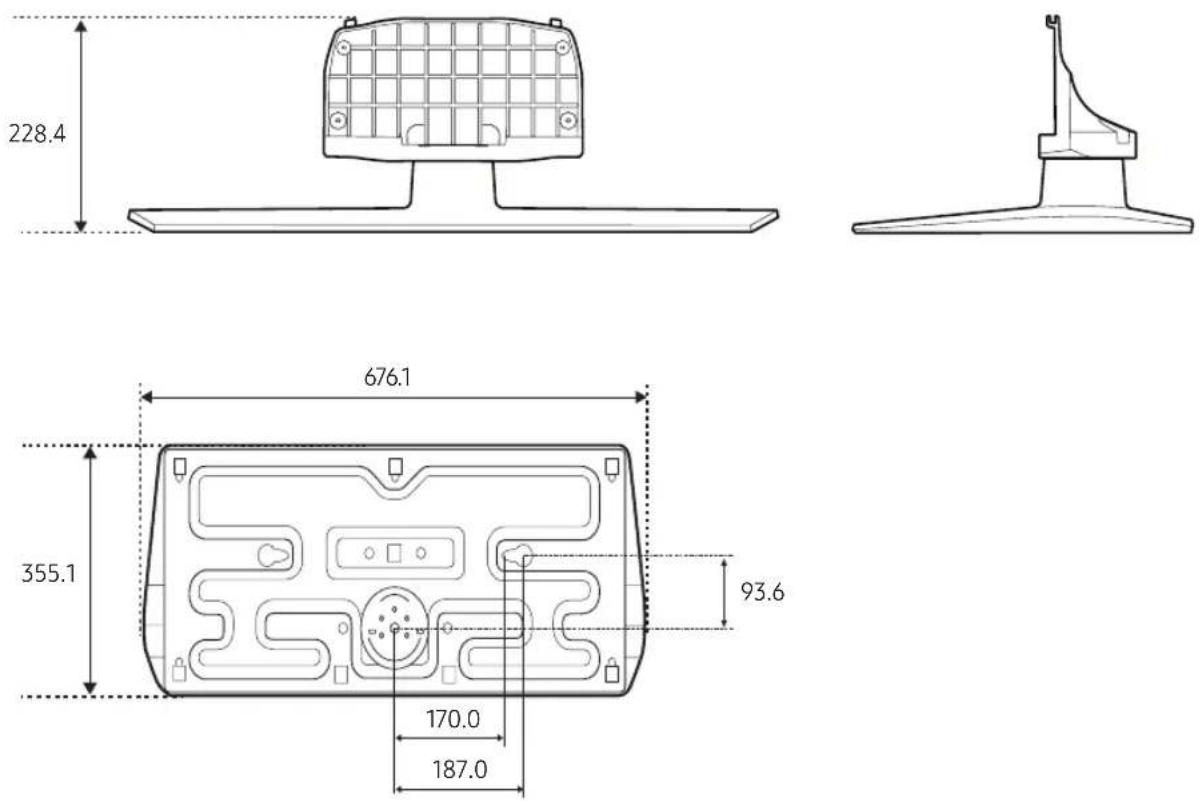
NOTE: All drawings are not necessarily to scale. Some dimensions are subject to change without prior notice. Refer to the dimensions prior to performing installation of your TV. Not responsible for typographical or printed errors.
© 2016 Samsung Electronics America, Inc
| Correct Disposal of This Product (Waste Electrical & Electronic Equipment)(Applicable in the European Union and other European countries with separate collection systems)This marking on the product, accessories or literature indicates that the product and its electronic accessories (e.g. charger, headset, USB cable) should not be disposed of with other household waste at the end of their working life. To prevent possible harm to the environment or human health from uncontrolled waste disposal, please separate these items from other types of waste and recycle them responsibly to promote the sustainable reuse of material resources. Household users should contact either the retailer where they purchased this product, or their local government office, for details of where and how they can take these items for environmentally safe recycling. Business users should contact their supplier and check the terms and conditions of the purchase contract. This product and its electronic accessories should not be mixed with other commercial wastes for disposal. | |
| Correct disposal of batteries in this product(Applicable in the European Union and other European countries with separate battery return systems.)This marking on the battery, manual or packaging indicates that the batteries in this product should not be disposed of with other household waste at the end of their working life. Where marked, the chemical symbols Hg, Cd or Pb indicate that the battery contains mercury, cadmium or lead above the reference levels in EC Directive 2006/66. If batteries are not properly disposed of, these substances can cause harm to human health or the environment. To protect natural resources and to promote material reuse, please separate batteries from other types of waste and recycle them through your local, free battery return system. |
Important Warranty Information Regarding Television Format Viewing
See the warranty card for more information on warranty terms.
Wide screen format LED Displays (with aspect ratios of 16:9, the ratio of the screen width to height) are primarily designed to view wide screen format full-motion video. The images displayed on them should primarily be in the wide screen 16:9 ratio format, or expanded to fill the screen if your model offers this feature and the images are constantly moving. Displaying stationary graphics and images on screen, such as the dark sidebars on nonexpanded standard format television video and programming, should be limited to no more than 5% of the total television viewing per week.
Additionally, viewing other stationary images and text such as stock market reports, video game displays, station logos, web sites or computer graphics and patterns, should be limited as described above for all televisions. Displaying stationary images that exceed the above guidelines can cause uneven aging of LED Displays that leave subtle, but permanent burned-in ghost images in the LED picture. To avoid this, vary the programming and images, and primarily display full screen moving images, not stationary patterns or dark bars. On LED models that offer picture sizing features, use these controls to view different formats as a full screen picture.
Be careful in the selection and duration of television formats used for viewing. Uneven LED aging as a result of format selection and use, as well as burned-in images, are not covered by your Samsung limited warranty.
• SAMSUNG ELECTRONICS NORTH AMERICAN LIMITED WARRANTY STATEMENT
Subject to the requirements, conditions, exclusions and limitations of the original Limited Warranty supplied with Samsung Electronics (SAMSUNG) products, and the requirements, conditions, exclusions and limitations contained herein, SAMSUNG will additionally provide Warranty Repair Service in the United States on SAMSUNG products purchased in Canada, and in Canada on SAMSUNG products purchased in the United States, for the warranty period originally specified, and to the Original Purchaser only.
The above described warranty repairs must be performed by a SAMSUNG Authorized Service Center. Along with this Statement, the Original Limited Warranty Statement and a dated Bill of Sale as Proof of Purchase must be presented to the Service Center.
Transportation to and from the Service Center is the responsibility of the purchaser. Conditions covered are limited only to manufacturing defects in material or workmanship, and only those encountered in normal use of the product.
Excluded, but not limited to, are any originally specified provisions for, in-home or on-site services, minimum or maximum repair times, exchanges or replacements, accessories, options, upgrades, or consumables.
For the location of a SAMSUNG Authorized Service Center, please call toll-free:
-In the United States: 1-866-894-0524
-In Canada: 1-800-213-8513
Disconnecting Device Instructions
Worded: "To disconnect the apparatus from the mains, the plug must be pulled out from the mains socket, therefore the mains plug shall be readily operable" or equivalent.
Outdoor Use Marking - UL
Worded: "WARNING - To Prevent damage which may result in fire or electric shock hazard, do not expose this appliance to rain or moisture" or equivalent.
Wet Location Marking - c-UL
Worded: "Apparatus shall not be exposed to dripping or splashing" and "Do not place a vessel containing water on this apparatus as this can result in a risk of fire or electric shock" or equivalent.
SAMSUNG
Contact SAMSUNG WORLD WIDE
If you have any questions or comments relating to Samsung products, please contact the SAMSUNG customer care center.
| Country Customer Care Center Web Site | |
| CANADA 1-800-SAMSUNG (726-7864) www.samsung.com/us/support | |
| MEXICO 1-800-SAMSUNG (726-7864) www.samsung.com/us/support | |
| U.S.A 1-866-894-0524 www.samsung.com/us/support |