
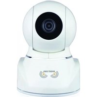
B-F900-81-8 - Security Camera Night Owl - Free user manual and instructions
Find the device manual for free B-F900-81-8 Night Owl in PDF.


| Product Type | Surveillance Security Camera |
| Brand | Night Owl |
| Model | B-F900-81-8 |
| Video Resolution | 1080p Full HD |
| Night Vision | Up to 100 ft (30m) infrared |
| Field of View | 90° wide angle |
| Connectivity | Wired (BNC) or wireless (Wi-Fi capable) |
| Power Supply | DC 12V / 1A (adapter included) |
| Dimensions (L x W x H) | 2.5 x 2.5 x 5.5 inches (approx.) |
| Weight | 0.7 lbs (320g) with bracket |
| Weatherproof Rating | IP66 (outdoor use) |
| Mounting Type | Wall or ceiling bracket included |
| Motion Detection | Yes, with push alerts |
| Audio | Built-in microphone (one-way audio) |
| Remote Viewing | Via Night Owl app (iOS/Android) |
| Storage | Compatible with Night Owl DVR/NVR (sold separately) |
| Maintenance | Clean lens with soft dry cloth; avoid moisture |
| Safety Certification | FCC, CE, RoHS compliant |
| Spare Parts & Repairability | Contact Night Owl support for replacement parts |
| Warranty | 1-year limited warranty |
Frequently Asked Questions - B-F900-81-8 Night Owl
User questions about B-F900-81-8 Night Owl
0 question about this device. Answer the ones you know or ask your own.
Ask a new question about this device
Download the instructions for your Security Camera in PDF format for free! Find your manual B-F900-81-8 - Night Owl and take your electronic device back in hand. On this page are published all the documents necessary for the use of your device. B-F900-81-8 by Night Owl.
USER MANUAL B-F900-81-8 Night Owl
Thank you for choosing Night Owl Security Products!
All of our products are backed by a conditional warranty which covers all hardware for 1 year from the date of purchase. Make the most of your warranty by completing the registration form online. In addition to warranty and technical support benefits, you will have access to our multitude of free instructional How-To-Videos. You can also view our instructional videos by clicking the "How to Videos" tabs within your product's page on our website.

Register at www.NightOwlSP.com!
Please see the warranty section of this manual for exclusions and additional details. Not all features and capabilities are shared across all models so you may see features which are not applicable. In addition you may see screen images that do not exactly match those on your display. This manual was accurate at the time it was completed. Due to our ongoing effort to constantly improve our products, functions may have been added or changed.
Scan or click the QR codes below to access our instructional videos that can assist you in configuring your Night Owl Security system.
DVR CONNECTIVITY

http://nightowlsp.com/dvr-qsg http://nightowlsp.com/startup-wizard-qsg
STARTUP WIZARD

MOBILE APP
SETUP

http://nightowlsp.com/mobile-app-qsg
TABLE
OF CONTENTS
Table of Contents
CHAPTER 1: FCC WARNINGS....7
CHAPTER 2: SAFETY INSTRUCTIONS....9
CHAPTER 3: SPECIFICATIONS....11
3.1 System Requirements 12
3.2 Package Contents 12
3.2.1 DVR Diagram 12
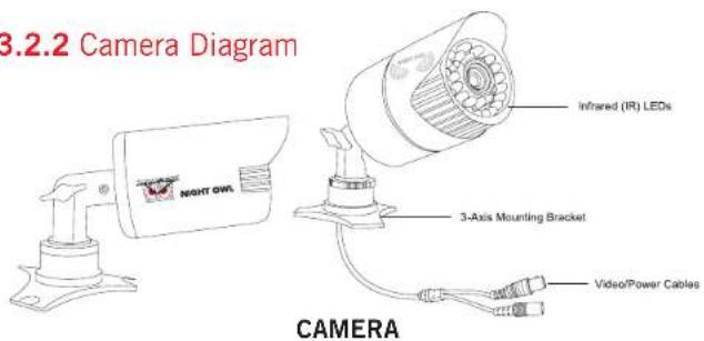
3.2.2 Camera Diagram 14
3.2.3 Mouse and Remote Diagrams....15
CHAPTER 4: CAMERA INSTALLATION....17
4.1 Video/Audio 18
4.2 Power 19
4.3 Mounting the Cameras 20
CHAPTER 5: DVR INSTALLATION....23
5.1 Connecting to a TV 24
5.2 Power....25
CHAPTER 6: GETTING STARTED ..... 27
6.1 Startup Wizard 28
6.2 Night Owl HD Mobile App 29
6.3 Displays and Icons 29
6.3.1 Login Screen 29
6.3.2 Live View (All Channels)....30
6.3.3 Live View (Single Channel).... 31
6.3.4 Menu Screen 32
CHAPTER 7: MENUS AND SETTINGS....33
7.1 General Menu 35
7.1.1 Display....35
a. Output 35
b. Privacy Zone....36
7.1.2 Network 37
a. Main 37
b. Substream 38
c. Email 38
d. Email Schedule.... 39
e. DDNS....39
7.1.3 Alarm....40
a. Motion 40
7.2 Cameras Menu 41
7.2.1 Settings 41
7.3 Record Menu (Playback) 42
7.3.1 General (Playback) 42
7.3.2 Events (Playback & Backup Files)....43
7.3.3 Settings (Record) 44
a. Basic 44
b. Record Schedule....44
c. Mainstream....45
7.4 Device Menu.... 46
7.4.1 HDD 46
7.4.2 PTZ 46
7.5 System Menu 47
7.5.1 General 47
a. Settings 48
b. DST 48
c. NTP 48
7.5.2 Users....49
7.5.3 Info 50
7.5.4 Log 51
7.6 Advanced Menu 52
7.6.1 Maintain 52
7.6.2 Events 53
7.6.3 Auto Upgrade 54
CHAPTER 8: REMOTE ACCESS....55
8.1 System Requirements 56
8.2 Setup....56
8.3 Network Configuration 57
8.3.1 Working System....57
8.3.2 Operating System 59
8.3.3 Port Forwarding....61
8.3.4 DDNS Registration 63
8.3.5 Adding the DDNS to Your DVR 64
CHAPTER 9: GLOSSARY 65
CHAPTER 10: WARRANTY 67
CHAPTER 11: TROUBLESHOOTING ....71
CHAPTER 12: CUSTOMER SUPPORT ....75
CHAPTER 13: USER INFORMATION ....77

SUPPORT
VIDEOS
For your reference, we have created an instructional video that explains the menu structure and functionality of your Night Owl recorder in detail. Click on the icon at any time to view Night Owl's instructional videos at www.youtube.com/user/NightOwlISP

ADVANCED
Night Owl's DVRs are manufactured for quality and ease of use. As such, our DVRs contain menus designed for advanced user's that should not be adjusted without having enhanced knowledge regarding the menu. In most cases the default settings allow for optimal functionality. The menus that should maintain the default settings are indicated with this icon.
CHAPTER 1
FCC WARNINGS

SUPPORT VIDEOS
Chapter 1: FCC Warnings
FCC
This equipment has been tested and found to comply with limits for Class B digital devices pursuant to Part 15 of Federal Communication Commission (FCC) rules.
These limits are designed to provide reasonable protection against frequency interference in residential installation. This equipment generates, uses, and can radiate radio frequency energy, and if not installed or used accordance with the instructions, may cause harmful interference to radio communication. However, there is no guarantee that interference will not occur in television reception, which can be determined by turning the equipment off and on. The user is encouraged to try and correct the interference by one or more of the following measures:
- Reorient or relocate the receiving antenna.
- Increase the separation between the equipment and the receiver.
- Connect the equipment into an outlet on a circuit different from that to which the receiver is connected.

CAUTION
The Federal Communications Commission warns the user that changes or modifications to the unit not expressly approved by the part responsible for compliance could void the user's authority to operate the equipment.
CHAPTER 2
SAFETY
INSTRUCTIONS

SUPPORT VIDEOS
Chapter 2: Safety Instructions
Use the provided power adapter.
Do not use this product with a power source that applies more than the specified voltage.
Never insert metal into the DVR case or its openings. Inserting metal into the DVR case may cause electric shock.
Do not operate in wet or dusty areas.
Avoid placing the DVR in areas such as a damp basement or dusty attic.
Do not expose the DVR to rain or use near water. If the DVR accidentally gets wet, unplug it and contact technical support immediately.
Keep product surfaces clean and dry. To clean the outside case of the DVR, use a lightly dampened cloth. Do not use cleaning solutions or solvents.
Do not install near any heat sources. Do not install the DVR near any heat sources such as stoves, heat registers radiators, or electronics (including amplifiers) that produce heat.
Unplug the DVR when moving it.
Make sure that the DVR is unplugged before you move it. When moving this device, be sure to handle it with care.
Make sure there is good air circulation around the DVR.
This DVR uses an internal hard drive, which generates heat during operation for video storage. Do not block vents on the DVR, as these vents reduce the generated heat while the system is running. Place this product in well-ventilated area.
Do not attempt to remove the top
cover. If you observe any abnormal operation, unplug the DVR immediately and contact technical support. Do not attempt to open the DVR to diagnose the cause of the problem.
Handle the DVR carefully.
If you drop the DVR on any hard surface, it may damage the device. If the DVR doesn't work properly due to physical damage, contact an authorized dealer for repair.
It is recommended to use your DVR with an uninterruptable power supply (UPS). Connecting your DVR and cameras to a UPS allows continuous operation even during power outages. The run-time duration will depend on the rating of the UPS used.

You may be subjected to severe electrical shock if you remove the cover of the DVR.
CHAPTER 3
SPECIFICATIONS

SUPPORT VIDEOS
Chapter 3: Specifications
3.1 System Requirements
Please be sure that your PC/MAC complies with the following specifications:
• PC Operating System: Windows Vista; Windows XP; Windows 7; Windows 8
• PC Browser: IE 8 or above; Google Chrome
• MAC Operating System: MAC OS X 10.7 and above
• MAC Browser: Safari 5.1 and above
Please be sure that your mobile device complies with the following specifications:
- Android: 3.0 and above
- iOS: 5.1 and above
3.2 Package Contents
- 1 x DVR
- Indoor/Outdoor Cameras*
- Bundles of Camera Cable*
- Mounting Hardware and Screws*
- HDMI Cable
- 1 x RJ-45 Cable (Ethernet)
- 1 x USB Mouse
• 1 x Remote Control (Includes Batteries)
- 1 x Software CD
• 1 x Quick Setup Guide
• 1 x Camera Power Adapter*
• 1 x DC 12V/2A DVR Power Adapter
- Camera Power Splitters*
• 3 x Night Owl Security Stickers

* Cameras, additional cables, power adapters and splitters only included in certain security kits. Check the product packaging for detailed kit contents.
3.2.1 DVR Diagrams

FRONT VIEW

REAR VIEW
Images used are for reference only. Your product may slightly vary.
- Audio Inputs – audio inputs allow for the connection of audio enabled cameras by connecting the white RCA plug to one of the audio inputs. After making the audio input connection, be sure to enable the audio function in the DVR's menu interface.
- Audio Output – audio output allows for the connection of an amplified speaker.
- Video Inputs – video inputs allow for the connection BNC cameras.
- HDMI Output - HDMI output allows for the video connection. If the TV / Monitor has an HDMI input, connect the HDMI cable from the HDMI output port on the DVR to the HDMI input port on your TV / Monitor.
-
VGA Output – VGA output allows for the video connection. If the TV / Monitor has a VGA input, connect the VGA cable from the VGA output port on the DVR to the VGA input port on your TV / Monitor.
-
RJ-45 (Ethernet) Port – RJ-45 port will be used to connect the DVR to your router/modem via the included Ethernet cable. Keep in mind, you can quickly network your DVR to begin viewing your cameras remotely right from your mobile device by completing the DVR's Startup Wizard once you have connected the DVR to your router and powered on the DVR.
- USB Ports – USB ports allow for the connections of a USB mouse and / or a USB flash drive. You will connect the included USB mouse to assist you in navigating the DVRs menu interface. You will connect a USB flash drive to download video files from the DVR and save them to your USB flash drive.
- Alarm/RS-485 (PTZ) Port – Alarm/RS-485 port allows for PTZ camera connection and integration with your monitored security company. Your security company must configure the DVR, not Night Owl. (Alarm block on 16CH DVRs only)
- Power Input - power input to connect the included 12V DC power supply.
- Video Output – Allows you to connect the DVR to your TV / Monitor if your TV / Monitor does not have a VGA or HDMI input.
- IR-EXT- allows you to connect an IR extender which extends the IR signal around corners, behind entertainment centers, or any situation where the line-of-sight between your DVR and your remote control isn't possible. To use it, connect the IR Extender to the IR-EXT input on the back of the DVR. Put the other end of the IR Extender somewhere that allows a direct line of sight between it and the remote.
- On/Off- allows you to turn your DVR On or Off.
Images used are for reference only. Your product may slightly vary.
NOTE: Connect all cameras locally before final placement to ensure that all components function properly.
3.2.3 Mouse and Remote Diagram
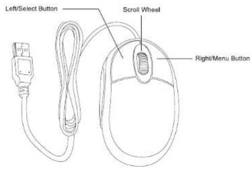
MOUSE
Live Viewing:
Double-click the left button on any camera view in split-screen mode to bring it to full screen display.
Double-click again to return to split-screen mode.
Right-click to show the control bar at the bottom of the screen.
Right-clicking again will hide the control bar.
In Setup:
Left-click to make a selection.
Right-click to cancel setup or return to previous screen.
To Enter Values:
Move the cursor to a blank field and click the mouse. A virtual keyboard will appear which supports numbers, letters and symbols. The Shift function will access symbols in addition to upper case letters.

REMOTE
CHAPTER 4
CAMERA
INSTALLATION

SUPPORT VIDEOS
Chapter 4: Camera Installation
4.1 Video/Audio
NOTE: Connect all cameras locally before final placement to ensure that all components function properly.
- Locate an included 60 foot camera cable.
- Connect a camera to one end of the cable by matching the BNC connectors (yellow) and DC power connectors (red).
- Audio enabled cameras will have an additional (white) RCA connection which will transmit the audio signal and will connect to the audio in port on the back of your DVR.

- Plug BNC connectors on the other end of the cable into a Video Input port on the back panel of the DVR.
- Repeat for each camera, noting the channel number each camera is plugged into.
4.2 Power
- Locate an included power splitter.
- Connect the power splitter to the remaining DC power connectors (red) of the cables.
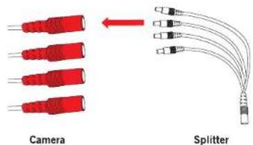
- Plug the power splitter into the labeled camera power supply, then plug the camera power supply into an available wall outlet or UPS. Keep in mind, Night Owl always recommends utilizing a surge protector to minimize the risk of damage caused to your DVR in the event of a power surge.


* Cameras, additional cables, power adapters and splitters only included in certain security kits. Check the product packaging for detailed kit contents.
Make sure all cameras are working prior to mounting by connecting them as described in the section above. Once all cameras are confirmed to be fully operational, you can run the cables and mount the cameras at their final locations.
4.3 Mounting the Cameras
Camera distance from viewing/recording device.
The further the camera is from the I or monitor, the higher the chances of signal degradation. The camera's power supply should be located as near to the camera as possible when the distance exceeds 200' as the power level will drop over extended distances resulting in vide
Connect all cameras locally before final placement to ensure that all components function properly.
Do not place near high voltage wires or other sources of electrical interference.
Electrical interference will degrade the quality of the signal.
Place camera out of reach to avoid vandalism.
Avoid direct exposure to weather. Do not place the camera where rain or snow will hit the lens directly nor should the camera be placed so that the sun or bright light shines directly into the lens. Your camera is weatherproof, but it will not work when submerged in water. Ensure that all power and video connections are not directly exposed to water and are protected from the elements.
Mounting surface. The mounting surface must hold at least four times the camera's total weight.
- Locate a camera and choose a location where you would like to mount the camera.
- Indicate screw positions by marking three holes on the surface where you plan to mount the camera, using the holes in the camera base as a guide.

- Using a drill bit slightly smaller than the included screw anchors, drill into the mounting surface using the guide marks you placed in the previous step.
- Insert the screw anchors.
- Line up the camera base holes with the screw anchors. Holding the base in place, insert screws and tighten until secure.

- Once the base is screwed in place, make sure that the camera is securely mounted by placing gentle pressure on the mount.
- Adjust the camera housing to point in the direction of the area you would like to monitor.

Don't feel like installing the system yourself? Let InstallerNet™ do the work for you! Contact us at 1-800-806-5513 or visit us at www.NightOwlSP.com.
CHAPTER 5
DVR INSTALLATION

SUPPORT VIDEOS
Chapter 5: DVR Installation
5.1 Connecting to a TV (via HDMI)
- Locate the included HDMI cable.

- Plug one end of the cable into the HDMI port on the back of the DVR.

- Connect the other end of the cable to an available HDMI input on your TV or monitor.

- Select the appropriate video input channel on your TV or monitor to view the DVR.

If your TV does not have an HDMI port, you will need to purchase a VGA or a BNC-to-RCA video cable.
For a VGA connection, attach one end of the VGA cable to the DVR VGA port and the other end to your TV VGA port.
For a BNC-to-RCA connection, attach the yellow RCA video connector of the cable to a yellow Video Input port on your TV. The opposite BNC video connector on the cable should then connect to the Video Out (V-OUT) port on the back of the DVR.
5.2 Power
- Locate the labeled DVR power adapter; the camera power adapter and DVR power adapter should never be interchanged.
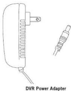
- Plug the included power adapter cable into the back of the DVR.

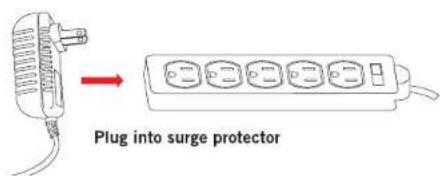
- Plug the other end of the power adapter cable into an available wall outlet. If you are using an uninterruptable power supply (UPS), plug the adapter cable into one of its output sockets. Keep in mind, Night Owl always recommends utilizing a surge protector to minimize the risk of damage caused to your DVR in the event of a power surge.

Night Owl's BB-86AH is our revolutionary battery backup designed for security DVR's. We recommend all customers to utilize the battery backup with your DVR. http://nightowlsp.com/bb-86ah.html
CHAPTER 6 GETTING STARTED

Chapter 6: Getting Started

6.1 Startup Wizard
When your DVR is powered on it will display the Night Owl logo while initializing. Scan or click the QR code to view our Startup Wizard video which shows the quick and easy steps in detail.

After initialization, you will be prompted to use the Startup Wizard. Follow the on-screen instructions to:
- Create a system user name and password.
- Connect your DVR to a router that is hard wired. Wireless router will not work.
- Follow the Startup Wizard instructions to add your DVR to your mobile device.


You can toggle the Startup Wizard from appearing at each power cycle by checking off the tick box at the welcome screen.

6.2 Night Owl HD Mobile App
The Night Owl HD mobile app lets you access your DVR remotely with live viewing from your tablet or smartphone. Download our
free Night Owl HD application from the iTunes App or Google Play store! Scan or click the QR code to view our Night Owl HD video which shows how to add and configure your smart device for remote viewing.

Once you have downloaded Night Owl HD and connected your DVR to your router, you can network your DVR by scanning the QR code which is located on the top of the DVR.
6.3 Displays and Icons
The following sections will describe the 3 main screens you will access for login, playback, recording, and configuration.
6.3.1 Login Screen

Any time you want to configure or adjust your system settings you will be required to log in by entering your username and password. It's important you save your login info or you won't be able to access your DVR. Be sure to store your user name and password in a safe location. You will need this information to access the main menu.
Device ID: the value in the field should match the value in the parentheses on the right. These numbers verify which device you are currently viewing.
User: enter the User name you created in the Startup Wizard or User Menu.
Password: enter the Password you created in the Startup Wizard or User Menu. If the password is incorrect you will be prompted to try again. Keep in mind the password is case sensitive and must be 8 characters long.
6.3.2 Live View (All Channels)
Live View is the default screen you will see when viewing all channels on your DVR. Right-click anywhere on-screen to bring up the icon menu to change viewing options or access the main menu. Rearrange the channel order by left clicking and dragging individual channels to other locations in the on-screen layout.

- Date and Time: current date and time of the system.
- Channel Name and Number: channel name and number.
- Menu: access the main menu to configure or adjust settings. Be sure to store your user name and password in a safe location. You will need this information to access the main menu.
- Lock Screen: manually locks or unlocks screen. Once the screen is locked, you will need to enter your username and password to gain access.
- Quad View: 4 channel viewing layout.
-
9-Channel View: 9 channel viewing layout.
-
Recording: indicates when a camera is currently recording.
- Multi-view: various layout options for viewing multiple channels at once.
- Auto Sequence: start/stop the slideshow sequence of each channel.
- Volume: mute or adjust the system volume.
- PTZ: open up the Pan, Tilt, Zoom (PTZ) menu. This function will only work when a PTZ camera is connected to your DVR.
- Cruise: starts/stops the cruise function of your PTZ camera.
- Picture-in-Picture 1: view channel 1 with an inset window showing another channel.
- Playback: access the recording/playback menu and functions.
6.3.3 Live View (Single Channel)
When in Live View, select a single channel to bring up additional controls and playback options. By double-clicking on the channel you can also view that channel in full screen mode.

- Record: click to begin live recording of the selected channel.
- Instant Playback: replay video footage stored on the HDD.
- Zoom: click and drag an area to zoom in and enhance. Right-click to return to the normal view.
- Color Setting: adjust the channel hue, contrast, brightness, and saturation.
6.3.4 Menu Screen
Access the main menu by right-clicking anywhere while in Live View and then selecting the menu icon.

At the menus you will be able to access settings and parameters for all aspects of your DVR system.
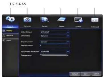
- General Menu: configure display, network, and alarm settings.
- Cameras Menu: access channel display and color settings.
- Record Menu: setup or modify general recording, triggered events, and recording settings.
- Device Menu: monitor available HDD space and access PTZ settings.
- System Menu: access general settings such as timestamp displays, user access, system info, and access logs.
- Advanced Menu: view and change maintenance settings, upgrades, and HDD alerts.
CHAPTER 7
MENUS
AND SETTINGS

SUPPORT VIDEOS
Chapter 7: Menus and Settings
Some menu screens will allow you to copy similar settings to multiple channels. Choose the channel you would like to copy information from in the first dropdown box (Copy), then select the channel you would like to copy the information to from the second dropdown box (To). Click Copy when the proper channels have been chosen.


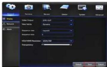
Be sure to Save all changes you make in the menus. If you do not save the changes, they will not be applied. You can also select the Default button to restore default settings for those parameters.

7.1 General Menu
The general menu will allow you to access display, network, and alarm settings for your DVR system.
ADVANCED
7.1.1 Display
a. Output: adjust the display resolution on your TV or monitor.
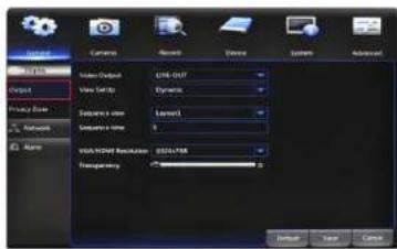
Video Output: defaulted to LIVE-OUT.
View Setup: choose between Dynamic and Static options.
The Dynamic option will allow you to adjust the number of visible channels in Live View. DVR is defaulted to Dynamic.
The Static option will lock the View Mode to Single, Quad, or Nine channel display.
Sequence View: set the channel order when viewing in sequential mode.
Sequence Time: adjust the duration each channel is displayed during a sequential view. You can select between 1 and 300 seconds per channel. To begin the auto sequence feature, click on the Auto Sequence icon which is located on the quick access bar.
VGA/HDMI Resolution: optimize the display resolution to best fit your TV/monitor. By default, the optimal resolution option will be selected automatically by the DVR.
Transparency: modify the menu transparency when displayed on screen.
b. Privacy Zone: create or modify up to 4 privacy zones per channel. These zones will not be visible to the cameras in Live View or during any recording.

Channel: choose which channel to apply a privacy zone to.
Privacy Zone: Enable or Disable privacy zones on the selected channel.
Area Setup: select the number of masks you would like to create or modify.
Mask Area: a single Live View of the selected channel will be displayed with the number of Areas selected in the previous line. Select, drag, and resize each area by left clicking the mouse to mask areas on camera that you do not want visible while recording or monitoring. Once the area(s) are selected, right-click to return to the menu.


7.1.2 Network
a. Main: find network values and optimize connectivity based on ADVANCED your Internet connection. In most cases the values should populate automatically once your DVR is connected to the Internet. The values in this section should only be adjusted if you are an advanced user and have extensive experience in device networking.
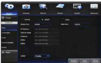
PPPOE: for broadband dial-up network users only. You will need to contact your ISP to retrieve the User Name and Password needed to complete this type of connection.
DHCP: the most common network connection type. These values will be gathered automatically from your ISP when connected.
Static: modify these values if you are using a static IP address. Information can be obtained from your router and ISP.
Media Port: allows access to your DVR from a mobile device. The default value of 9000 should generally be used for most cases.
Web Port: allows access to your DVR with your computer through your LAN or the Internet. In most cases the default value of 2049 or 2051 will provide the most optimal connectivity.
IP Address: network address of the connected DVR.
Subnet Mask: the range of IP addresses that can be found in the network. This should always be set to the default address 255.255.255.000.
Gateway: the connection between two networks. This should always be the IP address of the connected router.
DNS1: primary Domain Name System server address.
DNS2: secondary Domain Name System server address.
UPNP: Enable or Disable Universal Plug and Play abilities depending on your network device capabilities.
b. Substream: configure or optimize the video quality of your Live View.

Video: Enable or Disable video for the selected channel. If you select Disable, No video will be displayed from this channel during Live View.
FPS: increase or decrease the frames per second of the streaming video depending on your connection speed. A higher FPS will result in more data transfer but smoother video. A lower FPS will eliminate most lag but at the expense of video quality.
Bitrate: adjust the amount of data transferred while streaming. The default setting is sufficient for most networks.
Audio: click the tick box to record sound if your camera is audio enabled. Not all cameras are audio enabled; audio enabled cameras will have a white RCA connector to transmit the audio signal.
c. Email: Enable or Disable email alerts based on your alarm settings.
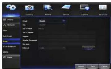
SSL: Enable or Disable to send encrypted email alerts.
SMTP Port: the access point for your email determined by your email service provider.
SMTP Server: this is the mail server address of your email provider. This information is determined by your email provider.
Sender: the email address that will send email alerts.
Sender Password: the password for the email address provided in Sender.
Receiver: the email address that will receive the email alerts.
Interval: set the duration between sending emails for multiple alerts.
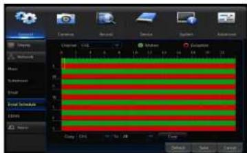
d. Email Schedule: choose when alert emails can be sent. Select Motion or Exception above the calendar and click the corresponding green or red boxes; you can highlight multiple boxes by left clicking and dragging. Highlighted boxes represent days and times in which emails will be sent. Motion refers to alerts sent when cameras are triggered by motion and Exception refers to events such as video loss or memory conflicts.
e. DDNS: Enable or Disable DDNS service to view your DVR from a computer.

Server: set to the NIGHTOWL server when using the Night Owl free domain name server.
Domain: set to the domain name you created when registering your DDNS.
User: the UserID created during the DDNS registration process.
Password: the password created during the DDNS registration process.
7.1.3 Alarm
a. Motion: configure the motion alarm settings for your DVR system.

Channel: select the channel to configure motion alarm settings.
Enable: activate motion alarms.
Sensitivity: adjust the level of motion detection. A lower setting will require more movement in the camera range to begin recording.
Buzzer: toggle between ON and OFF to enable an audible alert from the DVR.
Post Recording: set the amount of time to record after the motion is detected. You can select between 30 and 300 seconds.
Area: clicking Setup will allow you to configure areas which will and will not detect motion. Red boxes denote areas that will detect motion and uncolored boxes show areas that will not. When finished, right click to go back to menu.
Show Message: check the tick box to enable the display of a red "M" on-screen while in Live View mode. "M" means motion is occurring.
Send Email: check the tick box to send an email alert when motion is detected. See section 7.1.2. for email setup and configuration.
Full Screen: when this tick box is checked, the selected channel will go to full screen when motion is detected.
Record Channel: this option gives you the ability to start recording on the channels you select/highlight as soon as motion has been detected on the Channel selected above within the Channel field.
7.2 Cameras Menu
Adjust or modify individual camera settings connected to your DVR.

7.2.1 Settings
Channel: select the channel you want to configure a camera for.
Channel Name: create a name for the selected channel; this name will be displayed on-screen during live view and playback.
Position: change the position of Channel Name while viewing in Live View. For example U-L = Upper-Left; D-L = Down Left; U-R = Upper Right; D-R = Down Right
Color: click Setup to access a sub-menu to adjust the colors of the selected channel. In this sub-menu you can adjust the Hue, Brightness, Contrast, and Saturation of the image.
Covert: Enable or Disable the display of this channel. Enabling the Covert mode will not affect the channel's recording functions; only block the channel while viewing in live view mode.
Record Time: Enable or Disable the recording time display on-screen during playback mode.
Show Time: Enable or Disable the on-screen timestamp during live view mode.
7.3 Record Menu
From this menu you can enable recording, set video settings, and adjust streaming options.
7.3.1 General (Playback)
Search and playback all recorded video from this menu. Choose your desired date and times from the options below, then click Play to view recorded video. Right-click to exit back to the menu screen.

Channel: select the channel you would like to playback footage from. Type: search All, Normal or Motion video to playback.
Playback Channel: choose the desired channel to view footage from. Start Time: set the initial time parameter for your video search. End Time: set the end time parameter for your video search.

- Calendar: indicate the date to playback video.
- Channel Selection: choose the channels to display on-screen.
- Full Screen: hides the Calendar and Channel Selection panels.
-
Rewind: rewinds the recorded video.
-
Slow Forward: forwards the video at a slower speed.
- Play: plays video starting at the indicator on the timeline.
- Pause: pause the recorded video.
- Stop: stop the recorded video.
- Fast Forward: fast forward frame-by-frame of the recorded event.
- Zoom: click the icon and select the area on-screen to zoom in.
- Clip/Save: click once to set the start point of the video you would like to save. Press the icon again to select the end point of the video you would like
to save then choose whether you would like to save as an H.264 or AVI format. - Volume Scale: adjust the volume of the video in the selected channel(s).
- Start Time: indicates the beginning of the timeline on the selected Calendar date.
- End Time: indicates the end of the timeline.
- Timeline Length (24h, 2h, 1h, 30m): select the duration of the on-screen display of the timeline.
- Exit: double right click the mouse or click on the X to exit the playback screen.
7.3.2 Events (Playback & Backup Files)
Search for video from triggered events and quickly backup the video files for future reference. You can select either All, Normal or Motion.
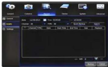
Date: select the date to search for event footage.
Time: choose a start and end time that the event happened.
Channel: pick the channel(s) with the desired video.
Type: select from All, Normal, or Motion video.
Search: once the parameters are set, click this button to retrieve video from the specified time period. You can choose to save the video file as an AVI or H.264 format.
Quick Backup: check the tick boxes to the left of the found video clip(s) and click this button to save that video to a USB Flash Drive. You can also Playback by right clicking on the icon located in the playback section.
7.3.3 Settings (Recordings)
View or modify general recording settings for your DVR system.

a. Basic: turn channel recording capabilities on or off.
Channel: select the channel you would like to configure.
Record: Enable or Disable recording capabilities for this channel.
Pre-Record: Enable or Disable pre-recording for this channel. Pre-recording is the amount of video captured prior to an alarm being triggered.

NOTE: By default, the DVR is configured to begin recording when motion is detected.
b. Record Schedule: set parameters for recording situations. For example, from this menu you can configure your camera on channel one to record from 1pm-9pm (Scheduled) and the remaining cameras to begin recording only when motion is detected (Motion).
Channel: select the channel to configure the recording schedule.
Normal Record: select this option to set the schedule for continuous recording. Once selected, highlight the boxes corresponding to the day and times that the channel should be recording. Click and drag to highlight multiple boxes green.
Motion Record: select this option to set the schedule for motion-activated recording. Once selected, highlight the boxes corresponding to the day and times that the DVR should record when motion is detected. By default, motion recording is always on.

c. Mainstream: configure or adjust the video settings to best optimize for your connection.
Resolution: choose between WD1 (960 x 576), WHD1 (960 x 288), or WCIF (480 x 240) resolutions based on your TV or monitor capabilities.
FPS: increase or decrease the frames per second of the streaming video depending on your connection speed. A higher FPS will result in more data transfer but smoother video. A lower FPS will eliminate most lag but at the expense of video quality.
Bitrate: adjust the amount of data transferred while streaming. The default setting is sufficient for most networks.
Audio: click the tick box to record sound if your camera is audio enabled. Audio enabled cameras are only included in certain kit models. Audio enabled cameras will have a white RCA plug to transmit the audio signal.
7.4 Device Menu
7.4.1 HDD
Check available memory on your DVR HDD and set recording parameters to optimize storage.

Select: if multiple drives are installed, choose the HDD you would like to customize.
Overwrite: by default, the Auto setting will overwrite the earliest footage once the HDD is full. Choose one of the other options to overwrite footage at the end of the desired time duration, starting with the earliest data. Off will record until the HDD has reached capacity.
Format HDD: click this button to format the selected drive. Keep in mind, formatting the HDD will erase all video files from the HDD.
7.4.2 PTZ
Configure settings on your DVR to control a PTZ-enabled camera.

Channel: choose the channel with a PTZ-enabled camera. Not all cameras are PTZ enabled.
Protocol: select Pelco-D or Pelco-P depending on the camera protocol. Both the DVR and camera should be set to the same setting.
Baudrate: indicate the frequency of communication to the PTZ camera. We recommend leaving the default setting which is 9600.
DataBit: select the amount of data to send during each transmission. 8 bits is standard for all modern data transmissions.
StopBit: select the amount of extra data to send each time a direction is sent to the camera. The stopbit serves as a buffer between commands and should be 1 (by default) when utilizing Night Owl's AHD PTZ camera.
Parity: detects corrupt commands sent to and from the PTZ camera. This should generally be left Disabled.
Cruise: Enable or Disable the PTZ cruise function, which allows the camera to automatically scan the area periodically with no manual input.
Address: enter an ID number for the PTZ camera, greater than 0. If using multiple PTZ cameras, ID numbers cannot be the same.
7.5 System Menu
7.5.1 General
Set or adjust basic DVR settings such as the time, date, and language.
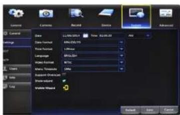
a. Settings: basic system configuration.
Date: manually set the date by left clicking on the calendar icon
Time: manually set the time by left clicking inside the time field.
Date Format: choose the display format for the date. You can select Month/Day/Year, Year/Month/Day or Day/Month/Year.
Time Format: select between a 12Hour or 24Hour display.
Language: pick between ENGLISH or SPANISH language preferences.
Video Format: NTSC or PAL formats are available to choose from. NTSC is the standard for video in North America.
Menu Timeouts: select the duration of time for an inactive menu to be displayed on-screen.
Support Overscan: when this option is enabled the DVR will automatically resize the viewing window to fit the aspect ratio of the connected monitor.
Show Wizard: check the tick box to display the Startup Wizard each time the DVR is powered on.
Mobile Wizard: click the mobile icon to launch mobile application setup portion of the Startup Wizard.
b. DST: configure Daylight Savings Time settings.
DST: Enable or Disable the Daylight Savings Time feature.
Time Offset: choose the amount of time (1Hour or 2Hours) to offset if DST is enabled.
Daylight Saving Time: indicate whether you would like this feature to be applied the week of or an exact date.
Start Time: select the date and time to apply the DST offset.
End Time: select the date and time to remove the DST offset.
c. NTP: sync your DVR to the Network Time Protocol standard time and date.
NTP: Enable or Disable the NTP sync feature.
Server Address: choose the NTP server in which to sync the date and time with.
Time Zone: indicate your current or desired time zone.
Update Now: after selecting the above options, click this button to apply the settings.
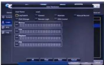
7.5.2 Users
Create and modify user's permissions.

Edit: select an existing user from the list to change the User Name, Enable or Disable password access, or create a new Password.

Permission: select a new user profile (e.g. user1) and press the Permission button to select which menus, settings, and playback/recording functions are available to that specific user and on which channels. All will give that user basic admin settings.
7.5.3 Info
View your DVR system's information and specifications at a glance. This menu will provide crucial device and network information to allow manual reconfiguration of your mobile application if needed. Keep in mind you can also scan the QR code on this screen using your Night Owl HD mobile application to quickly reconfigure your mobile device via our Owl Scan feature.

Device ID: create a unique device ID number if you are using multiple DVRs.
Device Name: create a unique device name for easy reference.
Device Type: product's model number.
Hardware Version: your current hardware version.
Software Version: your current software version.
IE Client Version: the current IE client version.
IP Address: the current DVR network address.
MAC Address: the DVR media access control address on the network.
HDD Capacity: the max capacity of installed hard drives.
Video Format: your current video recording format.
Media Port: By default should be left at 9000
Web Port: By default should be left at 2049 or 2051
P2P: The ID of your Peer to Peer (P2P) connection.
7.5.4 Log
Search for logs of all events and notifications on the DVR to playback or backup files.

Log Type: select the type of event log that you would like to Search for. Each choice corresponds to an action or event that was triggered and noted within the system. For example, System logs are recorded when the DVR time is synced with NTP (if enabled) or if the system is turned on or off.
Start Time: choose the initial date of your log search period.
End Time: choose the end date of your log search period.

Backup: in order to save a log, a USB flash drive must be inserted into one of the available USB ports on the back of the DVR. Select the log or logs you would like to save; you will then be prompted to specify which drive to save to.
7.6 Advanced Menu
Configure additional settings related to maintenance, hard drive space, and upgrades.
7.6.1 Maintain
Adjust settings related to default user access and reboot schedules.
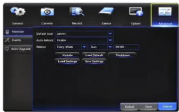
Default User: choose a user to default at the login screen at startup.
Auto Reboot: Enable or Disable a scheduled reboot.
Reboot: set the frequency of reboots if this feature is enabled.
Update: if any of the above settings were changed, click this button to save the new parameters.
Load Default: revert back to the standard reboot schedule.
Save Settings: save reboot settings to a USB flash drive.
Load Settings: load previously saved settings from a USB flash drive.
Shutdown: reboot the DVR.
7.6.2 Events
Configure notification settings for other triggered events not related to motion detection such as disk error, disk full or and/or video loss.

Event Type: choose the type of event you would like to create a notification for. Disk Full means you will receive a notification if the HDD is full. Disk Error refers to the status of the HDD and will notify you if it crashes or has become corrupt. Video Loss is the absence of video due to power loss disconnection.
Enable: turn notifications on or off for the selected Event Type.
Show Message: enable an icon to be displayed in Live View when the selected Event Type is triggered.
Send Email: send an email notification when this Event Type is detected.
Buzzer: turn an audible buzzer on for a duration of time to alert you when this Event Type happens. Choose OFF to disable this feature. You can select in between 10 and 60 seconds.
7.6.3 Auto Upgrade
Control settings for auto upgrades of the DVR software.

Auto Upgrade: Enable or Disable the auto upgrade feature. Firmware updates will be detected automatically when this feature is enabled. The default selection for the auto upgrade feature is enable.
Check For Updates: check this tick box to periodically check for updated software versions.
Detect: click this button to query your DVR and notify you if you are current or need to be updated.
Upgrade: if an upgrade is detected, click this button to download and install the new version.

CHAPTER 8
REMOTE ACCESS

SUPPORT VIDEOS
Chapter 8: Remote Access
This chapter will show you how to connect your DVR to the Internet. You will learn how to properly connect your DVR to your router/modem and setup port, Internet, and mobile configurations along DDNS registration.
8.1 System Requirements
You will need to have the following in order to be able to successfully connect the DVR to the Internet.
• High-speed Internet connection
- Router or modem with two open Ethernet ports
- Computer with Internet Explorer 7, 8, 9, or 10 and Windows® XP, Windows® Vista, Windows® 7, and Windows® 8 operating systems
- 2x Ethernet cables (1x included with the system; see image below)
8.2 Setup
Learn how to connect the DVR to your router/modem.

Ethernet

DVR

Router (Not Included)
NOTE: Do not connect the DVR to a wireless router.
8.3 Network Configuration
8.3.1 Windows® Operating Systems
Make sure that the DVR is properly connected to the router/modem and that you have a computer that works with Windows and connected to the same router.
Follow these steps to determine the basic information about your network:
- Press the Windows and R key at the same time on your computer's keyboard to bring up the Run window. Type "cmd" and press the Enter key.
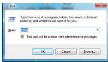
- In the command prompt window, type "ipconfig" and press Enter. Find the section named "Ethernet adapter Ethernet" or "Wireless LAN adapter Wi-Fi" and locate the "IPv4 Address" and write this address down e.g. 192.168.1.123.

-
Change the last three digits of the address to 150 and write this address down as well e.g. 192.168.1.150. This will become the IP address of your DVR at a later time.
-
Find "Default Gateway" in the same section and write this number down as well e.g. 192.168.1.1. You will need to enter this in the DVR network settings.
For the following steps, use the information that you just wrote down. To access the network settings on your DVR, go to the General Menu, then to Network > Main and choose the Static option.

- Manually enter the IP address into the IP Address field; this is the number that ends with 150. You may have to add placeholder zeros for any sections that do not contain three digits e.g. 192.168.1.150 -192.168.001.150.

- Confirm that the Subnet Mask is set to 255.255.255.000.

- Enter the "Default Gateway" number from the prior section into the Gateway field. Again you will need to add placeholder zeros in any sections that do not contain three digits e.g. 192.168.1.1 -192.168.001.001.

- DNS1 and DNS2 fields are auto-populated in most cases, if they are not they need to be set as follows: DNS1: [Gateway] DNS2: 8.8.8.8.
- Click the Save button to apply all changes.
- Reboot or power cycle the DVR.
NOTE: Write these addresses down in the User Information section at the end of the manual for future reference.
8.3.2 Mac® Operating Systems
Make sure that the DVR is properly connected to the router/modem.
Follow these steps to determine basic information about your network:
- Select the Airport icon on your computer screen and choose the "Open Network Preferences" option.
- Choose Ethernet and select the Advanced button in the lower right corner.
- Select the TCP/IP tab at the top to display your computer's network information.
- Write down the "IPv4 address."
- Change the last three digits of the address to 150 and write this address down as well e.g. 192.168.1.150. This will become the IP address of your DVR at a later time.
- Make note of the IP address listed for router. You will need to enter this into the DVR network settings.
For the following steps, use the information that you just wrote down. To access the network settings on your DVR, go to the General Menu, then to Network > Main and choose the Static option.
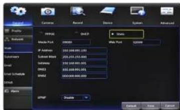
- Manually enter the IP address into the IP Address field; this is the number that ends with 150. You may have to add placeholder zeros for any sections that do not contain three digits e.g. 192.168.1.150 - 192.168.001.150.

- Confirm that the Subnet Mask is set to 255.255.255.000.
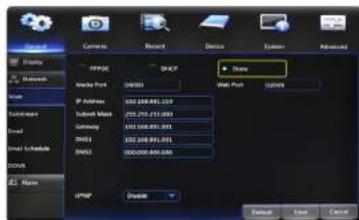
- Enter the "Default Gateway" number from the prior section into the Gateway field. Again you will need to add placeholder zeros in any sections that do not contain three digits e.g. 192.168.1.1 -192.168.001.001.

- DNS1 and DNS2 fields are auto-populated in most cases, if they are not they need to be set as follows: DNS1: [Gateway] DNS2: 8.8.8.8.
- Click the Save button to apply all changes.
- Reboot or power cycle the DVR.
NOTE: Write these addresses down in the User Information section at the end of the manual for future reference.
8.3.3 Port Configuration
After you have configured the network settings, you will need to forward the necessary ports to be able to view the DVR over the Internet.
Refer to your router's documentation to see how port forwarding works for your device. This process may be referred to as "Port Forwarding," "Port Mapping," or "Virtual Server."
Below are some general considerations to keep in mind to make sure that the appropriate ports are forwarded:
- Go to http://whatismylp.com. Your public IP address will appear at the top of the page; write this number down.
- Open the Internet Explorer browser and type in your IP address in the URL bar.
- Log in to your router using your user name and password. If you do not know your router's user name and password you will need to contact your ISP or the router manual/support to retrieve that information.
-
Once logged in to your router, go to the settings related to port forwarding.
-
You will need to enter a new port forwarding entry for each port that your DVR uses: Media Port (9000), Web Port (2049 or 2051). Repeat the steps below for each entry.
- When entering the port numbers and IP address into your router's port forwarding section, you will need to remove any leading zeros e.g. 09000 → 9000, 192.168.000.150 -192.168.0.150, etc.
- Additionally most router menus will ask you to enter the following information in order to forward a port; the language and naming on your particular router may be different than the below but the same principles will apply:
• Application Name: create a unique name for your DVR system.
- Public Port: select the port to forward: Media Port (9000), Web Port (2049 or 2051), or Server Port (2050).
- Private Port: set to the same number you entered for the Public Port.
- Port Type/Protocol: if your router has an option for both, use TCP and UDP. If your router allows either TCP or UDP port types, use TCP.
- Host IP Address: set to your DVR IP address ending in 150 that you wrote down earlier.
Once you have forwarded the necessary ports on your router, you should check to make sure they have been correctly forwarded.
- Go to http://www.yougetsignal.com/tools/open-ports/.
- Type in port 9000 and select the Check button to see if the port is open or closed.
- Type in port 2049 or 2051 and select the Check button to see if the port is open or closed.
- All ports should be open. If any ports test as closed, that port is not forwarded correctly.
NOTE: Write you external address in the User Information section at the end of the manual.
8.3.4 DDNS Registration
This option allows you to set up a free website address that will point back to the DVR, regardless of whether or not the IP address changes. If you do not have a static IP address, you should use this option.
Follow the steps below to register a free domain name/DDNS.
- Go to http://www.nightowldvr.com.
- Select the Registration button located at the top left corner of the page.

- Complete the New User Registration form. Write down the UserID and Password information.
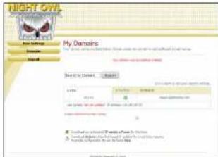
- Create a domain name.
- If the domain name that you have chosen is available, you will see a window that tells you that your domain was successfully created. If the domain name is taken, try again until you find an available name.
NOTE: Write the registered domain name down in the User Information section at the end of the manual.
8.3.5 Adding the DDNS to Your DVR
After you have registered for a free domain name you will need to add that domain to your DVR.
To do so you will need to access the DDNS settings. Go to the General menu and then to the Network settings and the DDNS section.

- Set the DDNS field to Enable.
- Verify that the Server field is still set to NIGHTOWL.
- In the Domain field, input the domain name that was created during the DDNS registration.
- Input the UserID and Password you created at registration into the User and Password fields respectively.
- Click Save to apply the changes.
CHAPTER 9 GLOSSARY

SUPPORT VIDEOS
Chapter 9: Glossary
DDNS: Dynamic Domain Naming System. Method for automatically updating hostnames, address, or other information like a URL on a given name server.
DHCP: Dynamic Host Configuration Protocol. A network protocol that allows a server to automatically assign a device and IP address.
FPS: Frames Per Second.
ISP: Internet Service Provider. An organization that provides services for accessing or using the Internet.
IP: Internet Protocol. Protocol for standard communications across the Internet.
PPPOE: Point-to-Point Protocol Over Ethernet. Specifications needed to connect multiple addresses on a local network to a remote site.
SSL: Secure Sockets Layer. Provides a secure connection between web browsers and websites.
SMTP: Simple Mail Transfer Protocol. Standards used for email transmission.
UPS: Uninterrupted Power Supply. Device used to keep the DVR and cameras powered when the main power supply is lost or disconnected.
CHAPTER 10 WARRANTY
Chapter 10: Warranty
NIGHT OWL, LLC ('Night Owl') provides the following warranty to the original retail purchaser only (the "Purchaser") with respect to this product (the "Product"):
For a period of one (1) year after the date of sale, the Product shall be free from manufacturing defects in material and workmanship. In the event that the Product is defective, the Purchaser must return the Product at Purchaser's cost (no CODs) to the address below, with the original proof of purchase receipt. In its sole discretion, Night Owl will either repair or replace the Product at no additional cost to the Purchaser. Any replacement Product (or parts) will be covered by the same warranty as the original Product through the expiration date of the original warranty period.
Exclusions
This warranty does not apply to the following parts or upon the following events:
- Bulbs, LEDs and batteries;
- The Product was not used or installed in the manner described in the installation instructions;
- Negligent use of the Product, or misuse or abuse of the Product;
- Electrical short circuits or power surges;
- Use of replacement parts not supplied by Night Owl;
- Product is either tampered with, modified, or repaired by another service provider;
- Product has not been maintained in accordance;
- Accident, fire, flood or other acts of God;
- Failure to use Night Owl approved accessories;
- Defects or damages arising by use of the Produce in other than normal conditions (including normal atmospheric, moisture and humidity conditions).
Except as otherwise prohibited by law, this warranty is in lieu of other warranties, express or implied, and Night Owl neither assumes no authorizes any person to assume for it any other obligation or liability in connection with the sale or service of the Product.
In no event shall Night Owl be liable for any special or consequential damages arising from the use of the Product or arising from the malfunctioning or non-functioning of the Product, or for any delay in the performance of this warranty due to any cause beyond its control. This warranty shall not apply to installation or the removal and reinstallation of products after repair.
Night Owl does not make any claims or warranties of any kind whatsoever regarding the Product's potential, ability or effectiveness to prevent, minimize, or in any way affect personal or property damage or injury. Night Owl is not responsible for any personal damage, loss or theft related to the Product or to its use for any harm, whether physical or mental related thereto. Any and all claims or statements, whether written or verbal, by salespeople, retailers, dealers or distributors to the contrary are not authorized by Night Owl, and do not affect this provision of this warranty.
Returns Under this Warranty
In order to obtain service, please make sure that you have registered your product on-line no later than thirty (30) days after purchase at www.NightOwlSP.com in the warranty registration section or in any other manner described in the instructions.
Disclaimer
Certain uses, publication and/or distribution of video/audio recordings from security cameras and/or audio devices are prohibited or restricted by federal, state and local laws. When enabling and/or using audio recording features with your hidden security camera, be sure to comply with the laws in your country, state and locality.
Mac and Mac OS X are registered trademarks of Apple Inc. Windows, Windows XP, Windows Vista, Windows 7 and Windows 8 are registered trademarks of Microsoft Corporation in the United States and/or other countries.
CHAPTER 11
TROUBLESHOOTING

SUPPORT VIDEOS
Chapter 11: Troubleshooting
If a problem occurs, you may be able to easily correct it yourself. The following table describes some common issues and their most likely solutions. Please refer to the table before calling technical support.
| Error Possible Causes Solutions | ||
| System is not receiving power, or is not powering up. | Cable from power adapter is loose or is unplugged. | 1. Confirm that all cables are connected correctly.2. Confirm that the power adapter is securely connected to the back of the unit. |
| Cables are connected, but system is not receiving sufficient power. | 1. Confirm that the system is powered ON (LED indicators on the front should be ON).2. If the unit is connected through a power bar or surge protector, try bypassing the bar and connecting the power directly to the wall outlet.3. Confirm that there is power at the outlet.4. Connecting the power cable to another outlet.5. Test the outlet with another plugged device (such as a phone charger). | |
| Remote control is not detected by the system. | Battery in the remote control is drained. | Install two fresh AAA alkaline batteries in the remote control. |
| There are no batteries in the remote control. | ||
| Hard drive is not detected by the system. | Hard drive cables are loose or not properly connected. | Remove the cover and check that the hard drive cables are firmly connected. |
| There is no hard drive in the system. | Open the cover and install a 3.5" SATA hard drive. | |
| Hard drive is full (0%) and the unit is no longer recording. | Overwrite is not enabled. | Go to the Device Menu > HDD and ensure that Overwrite is set to Auto. |
| Mouse not detected by system. | Mouse cable is not firmly connected to the system. | Firmly connect the mouse cable to the USB Mouse port on the front panel. |
| Mouse is not connected to the system. | ||
| System needs to be reset. | Power off the system (disconnect power cable). Firmly connect a USB mouse to the USB Mouse port on the front panel of the system. Reconnect the power cable to the DC 19V port on the real panel. | |
| Error Possible Causes Solutions | ||
| There is no picture on selected channels/camera picture is not being displayed. | Camera cables are loose of have become disconnected. | 1. Check the camera video cable and connections.2. Disconnect and reconnect the cable at the system and at the camera.3. Try moving the camera to another channel or use another cable. |
| The image on the DVR appears, but does not have sound. | Audio cables are loose or have been disconnected. | Check the AUDIO connection to the DVR. |
| Audio channels are disable. | Left click in Live View to bring up the Volume control and ensure that the channel(s) are not low or muted. | |
| Volume on external speakers (not included) is low or off. | Increase volume on external speakers (not included). | |
| A “whirring” noise is coming from the system. | Fan is active. | The noise means the exhaust fan is working normal. |
| The system beeps at startup. The beep at startup is normal. | ||
| The system beeps during motion detection. | Motion detection is enabled, but the alarm buzzer is activated. | Go to the General Menu > Alarm, select the channel and turn Buzzer to OFF. |
| I am not receiving email notifications. | Email notification is disabled. | See section 7.1.2. for details on email configuration. |
| Default setting is disabled, but you have not entered your own SMTP information. | ||
CHAPTER 12
CUSTOMER SUPPORT

SUPPORT VIDEOS
Chapter 12: Customer Support
Before you return to the store, we might be able to save you a trip:
ONLINE
- www.NightOwlSP.com
• 24/7 Product Support - How-To Videos
- Manuals
- Firmware Updates, etc.
• Technical Support: support@NightOwlSP.com
• Sales Support: sales@NightOwlSP.com
PHONE (English & Spanish)
- Technical Support: register at www.NightOwlSP.com to receive technical phone support.
• Sales Support: 1.561.265.5272
• Professional Installation: 1.800.806.5513
CHAPTER 13
USER INFORMATION

SUPPORT VIDEOS
Chapter 13: User Information
Be sure to write down all the important information below and place it in a secure location.
General DVR Information
Admin Password: ____
User Password: ____
Mac Address: ____
Serial Number: ____
Internet Login Information
Internal IP Address: ____
Public IP Address: ____
DDNS Name: ____
DDNS UserID: ____
DDNS Password: ____
Media Port: ____
Web Port: ____
NIGHT OWL


- THANK YOU FOR CHOOSING NIGHT OWL SECURITY PRODUCTS
- REGISTER AT WWW.NIGHTOWLSP.COM
- SCAN OR CLICK THE QR CODES BELOW TO ACCESS OUR INSTRUCTIONAL VIDEOS THAT CAN ASSIST YOU IN CONFIGURING YOUR NIGHT OWL SECURITY SYSTEM
- TABLE
- OF CONTENTS
- TABLE OF CONTENTS
- CHAPTER 8: REMOTE ACCESS....55
- CHAPTER 9: GLOSSARY 65
- CHAPTER 10: WARRANTY 67
- CHAPTER 11: TROUBLESHOOTING ....71
- CHAPTER 12: CUSTOMER SUPPORT ....75
- CHAPTER 13: USER INFORMATION ....77
- CHAPTER 1
- FCC WARNINGS
- CHAPTER 1: FCC WARNINGS
- FCC
- CAUTION
- CHAPTER 2
- SAFETY
- INSTRUCTIONS
- CHAPTER 2: SAFETY INSTRUCTIONS
- CHAPTER 3
- SPECIFICATIONS
- CHAPTER 3: SPECIFICATIONS
- 3.1 SYSTEM REQUIREMENTS
- 3.2 PACKAGE CONTENTS
- 3.2.1 DVR DIAGRAMS
- REAR VIEW
- 3.2.3 MOUSE AND REMOTE DIAGRAM
- LIVE VIEWING
- IN SETUP
- TO ENTER VALUES
- CHAPTER 4
- CAMERA
- INSTALLATION
- CHAPTER 4: CAMERA INSTALLATION
- 4.1 VIDEO/AUDIO
- 4.2 POWER
- 4.3 MOUNTING THE CAMERAS
- CAMERA DISTANCE FROM VIEWING/RECORDING DEVICE
- DO NOT PLACE NEAR HIGH VOLTAGE WIRES OR OTHER SOURCES OF ELECTRICAL INTERFERENCE
- PLACE CAMERA OUT OF REACH TO AVOID VANDALISM
- CHAPTER 5
- DVR INSTALLATION
- CHAPTER 5: DVR INSTALLATION
- 5.1 CONNECTING TO A TV (VIA HDMI)
- 5.2 POWER
- CHAPTER 6 GETTING STARTED
- CHAPTER 6: GETTING STARTED
- 6.1 STARTUP WIZARD
- 6.2 NIGHT OWL HD MOBILE APP
- 6.3 DISPLAYS AND ICONS
- 6.3.1 LOGIN SCREEN
- 6.3.2 LIVE VIEW (ALL CHANNELS)
- 6.3.3 LIVE VIEW (SINGLE CHANNEL)
- 6.3.4 MENU SCREEN
- CHAPTER 7
- MENUS
- AND SETTINGS
- CHAPTER 7: MENUS AND SETTINGS
- 7.1 GENERAL MENU
- 7.1.1 DISPLAY
- 7.1.2 NETWORK
- 7.1.3 ALARM
- 7.2 CAMERAS MENU
- 7.2.1 SETTINGS
- 7.3 RECORD MENU
- 7.3.1 GENERAL (PLAYBACK)
- 7.3.2 EVENTS (PLAYBACK & BACKUP FILES)
- 7.3.3 SETTINGS (RECORDINGS)
- 7.4 DEVICE MENU
- 7.4.1 HDD
- 7.4.2 PTZ
- 7.5 SYSTEM MENU
- 7.5.1 GENERAL
- 7.5.2 USERS
- 7.5.3 INFO
- 7.5.4 LOG
- 7.6 ADVANCED MENU
- 7.6.1 MAINTAIN
- 7.6.2 EVENTS
- 7.6.3 AUTO UPGRADE
- CHAPTER 8
- REMOTE ACCESS
- CHAPTER 8: REMOTE ACCESS
- 8.1 SYSTEM REQUIREMENTS
- 8.2 SETUP
- 8.3 NETWORK CONFIGURATION
- 8.3.1 WINDOWS® OPERATING SYSTEMS
- 8.3.2 MAC® OPERATING SYSTEMS
- 8.3.3 PORT CONFIGURATION
- 8.3.4 DDNS REGISTRATION
- 8.3.5 ADDING THE DDNS TO YOUR DVR
- CHAPTER 9 GLOSSARY
- CHAPTER 9: GLOSSARY
- CHAPTER 10 WARRANTY
- CHAPTER 10: WARRANTY
- EXCLUSIONS
- RETURNS UNDER THIS WARRANTY
- DISCLAIMER
- CHAPTER 11
- TROUBLESHOOTING
- CHAPTER 11: TROUBLESHOOTING
- CHAPTER 12
- CUSTOMER SUPPORT
- CHAPTER 12: CUSTOMER SUPPORT
- ONLINE
- PHONE (ENGLISH & SPANISH)
- CHAPTER 13
- USER INFORMATION
- CHAPTER 13: USER INFORMATION
- GENERAL DVR INFORMATION
- INTERNET LOGIN INFORMATION
Brand : Night Owl
Model : B-F900-81-8
Category : Security Camera