
NR8301 - Voice recorder Vivotek - Free user manual and instructions
Find the device manual for free NR8301 Vivotek in PDF.


| Product Type | 8-Channel Network Video Recorder (NVR) |
| Model | NR8301 |
| Brand | Vivotek |
| Dimensions | 446.4 mm (W) x 330.2 mm (D) x 43.6 mm (H) |
| Weight | 4.7 kg |
| Power Supply | 100-240V AC, 2A, 50-60Hz; 802.3af PoE compliant |
| Power Consumption | Max 0.96 W (without PoE cameras); Max 120 W (with 8 PoE cameras) |
| Video Compression | H.264, MJPEG, MPEG-4 |
| Audio Compression | AAC, G.AMR, G.711 |
| Recording Throughput | Total 50 Mbps; 8 x 30 fps @ 1280x800 |
| Hard Disk Support | 2 x 3.5" SATA I/II HDD, up to 4TB total (RAID 0/1) |
| Network Interfaces | 1 x Gigabit RJ45 (WAN); 8 x 10/100 RJ45 (LAN) with PoE |
| Other Connectors | USB socket, Terminal block (4 DI, 1 DO, 1 power output) |
| Operating Temperature | 0°C to 50°C (32°F to 122°F) |
| Humidity | 20% to 80% RH |
| Certifications | CE, FCC, VCCI, C-Tick, CB |
| Main Features | 8-CH H.264 recording, RAID 0/1, PoE, auto camera detection, PTZ control, event triggers, email/FTP notifications |
| Maintenance | Reboot, factory reset, firmware upgrade via web interface; HDD formatting in Storage menu |
| Security | Multi-level user access (admin/operator/viewer), IP address filtering, password protection |
| Spare Parts / Repairability | Lockable, removable HDD trays; eSATA (NR8201) not on NR8301; USB backup; standard SATA HDDs |
| Warranty | 24 months |
Frequently Asked Questions - NR8301 Vivotek
User questions about NR8301 Vivotek
0 question about this device. Answer the ones you know or ask your own.
Ask a new question about this device
Download the instructions for your Voice recorder in PDF format for free! Find your manual NR8301 - Vivotek and take your electronic device back in hand. On this page are published all the documents necessary for the use of your device. NR8301 by Vivotek.
USER MANUAL NR8301 Vivotek
H.264 • Compatible with VAST CMS • Lockable HDD & Rack Mount Design
Network
Video Recorder
natural_image
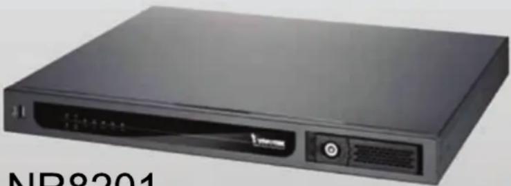
Black electronic device labeled 'NR8201' with ports and indicator lights (no readable text beyond label)NR8201
4-CH Viewing & Recording
External eSATA Interface
natural_image
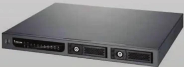
Front view of a black server rack with two ports and indicator lights (no visible text or labels)NR8301
8-CH Viewing & Recording
RAID0 & 1 Scalable Storage
Rev. 1.4.1
Table of Contents
Overview....3
Read before use....3
Package contents....3
Revision History ....3
Physical description....4
Installation 8
Hard Disk installation....8
Network deployment....9
Home Page....20
Configuration 22
Device 22
Network 27
LAN 28
Access list 30
DDNS 31
Security 33
Schedule 35
Recording Policy 37
Trigger 40
Layout......43
System 44
Maintenance....47
Storage....48
Backup 49
System log....50
Joystick....51
Monitor....52
User Interface of Monitor Page 52
Functions of Monitor Page 54
History 57
User Interface of History Page 57
Functions of History Page 58
Appendix....63
Technical Specifications 63
URL Commands for the Network Camera....64
Overview
VIVOTEK's NR8201/8301 network video recorder offers an elegant recording solution for VIVOTEK network cameras and performs real-time monitoring and recording simultaneously. It supports up to 4-CH (NR8201) and 8-CH (NR8301) H.264, MJPEG, and MPEG-4 video and provides multiple recording modes including alarm recording, scheduled recording, manual recording and continuous recording. The installation is very simple as the camera is able to be inserted automatically when it's plugged in. It also offers a user-friendly interface for the user to configure the network settings and the camera control. Moreover, the 802.3af compliant PoE (Power-over-Ethernet) is able to reduce the complex of the installation, making NR8201/8301 the cost-effective recording systems.
The user can utilize the NR8201/8301 to record high-definition mega-pixel videos on removable hard disk(s) with large capacity and a USB interface for data backup. The NR8201 also supports an external hard disk from the eSATA interface, and the NR8301 supports RAID 0 and 1 storage solution. The built-in gateway separates the network camera connection and the data network connection for the prevention of network congestion. Functional four digital inputs and one digital output interfaces is capable of integrating with the security sensors and alarms. The NR8201/8301 are comprehensive network video recorders featuring with multiple functions to provide the best quality and highest performance in network video recording.
Read before use
The use of surveillance devices may be prohibited by law in your country. It is the user's responsibility to ensure that the operation of such devices is legal before installing this unit for its intended use.
It is important to first verify that all contents received are complete according to the Package contents listed below. Take notice of the warnings in Quick Installation Guide before the Network Video Recorder is installed; then carefully read and follow the instructions in the Installation chapter to avoid damages due to faulty assembly and installation. This also ensures the product is used properly as intended.
The Network Video Recorder is a network device and its use should be straightforward for those who have basic network knowledge. It is designed for various applications including audio/video recording, general security/surveillance, etc. The Configuration chapter suggests ways to best utilize the Network Video Recorder and ensure proper operations.
Package contents
■ NR8201/8301
■ Rack mount kit
■ Power cord
■ Software CD
■ Warranty card
■ Quick installation guide
Revision History
■ Rev. 1.4: Added notifications forbidding the connections from PoE ports to non-PoE devices.
■ Rev. 1.4.1: * Corrected and added supported and unsupported connection diagrams to page 11 and page 28. Revised network configuration details for LAN and WAN ports.
* Corrected the use of reset and power buttons for restoring defaults.
Physical description
Front panel
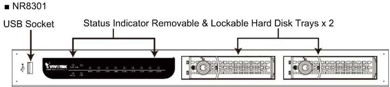
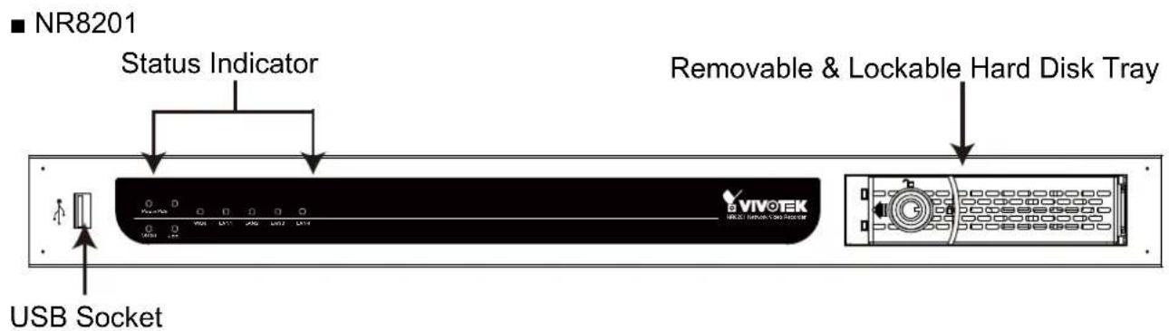
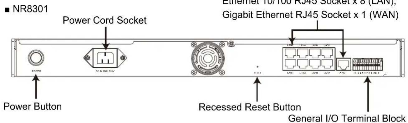
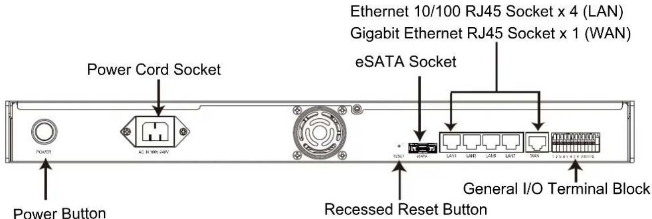
Connectors
■ NR8201
General I/O Terminal Block
This Network Camera provides a general I/O terminal block which is used to connect external input / output devices. The pin definitions are described below.
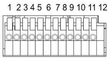
1: Power
2: Relay output COM
3: Relay output N.O.
4: Digital Input 1
5: Digital Input 1 Ground
6: Digital Input 2
7: Digital Input 2 Ground
8: Digital Input 3
9: Digital Input 3 Ground
10: Digital Input 4
11: Digital Input 4 Ground
12: Ground
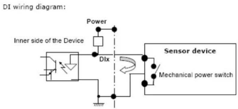
DI/DO Diagram
Refer to the following illustration for connection method.
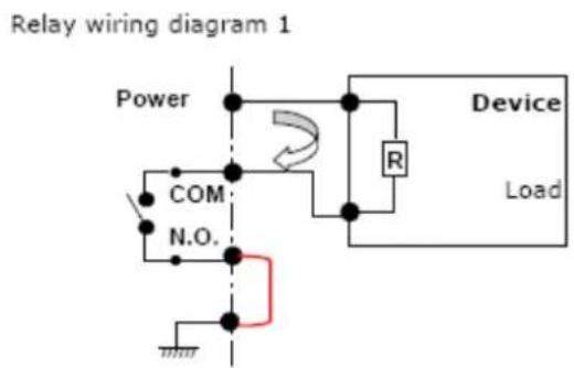
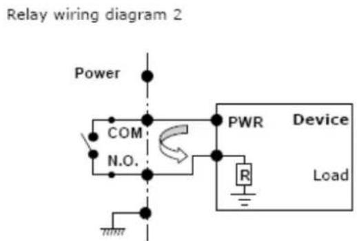
Status LED
The LED indicates the status of the Network Video Recorder.
| LED Status | Indication | |
| Power | On | Power on |
| Off Power off | ||
| POE | On | Power on |
| Off Power off | ||
| Status | Off System not ready | |
| Green System ready | ||
| Blink Green During system boot up and maintenance | ||
| Orange System failure | ||
| Blink Orange System warning | ||
| Hard disk Off No HDD attached | ||
| Green HDD normal (for 8301, either of the disks) | ||
| Blink Green Hard disk is recording or initializing (for 8301, either of the disks) | ||
| Blink Orange HDD warning (for 8301, either of the disks) | ||
| WAN On With connection on | ||
| Off No connection | ||
| Blink WAN port activated | ||
| LAN (1-8) | On With connection | |
| Off No connection | ||
| Blink LAN port activated (1-8) | ||
Hardware System Requirement
Computer:
■ Microsoft Windows XP Professional SP2 or above
■ Internet Explorer 6.0 or later
Hard disk:
■NR8201: Support 1 x 3.5" SATA I/II HDD, up to 2TB (Supports external eSATA interface)
■NR8301: Support 2 x 3.5" SATA I/II HDD, up to 4TB (Supports RAID0 and RAID1)
Hardware Reset
There is an indented reset button on the back panel of the Network Video Recorder. It is used to reboot the Network Video Recorder or restore the Network Video Recorder to factory default. Sometimes rebooting the Network Video Recorder could set it back to normal state. If the problems still remain after rebooted, restore the Network Video Recorder to factory default and install again.
Reboot: Press and release the indented reset button. All status LED will extinguish and then power on again. Wait for the Status LED to blink and then become steady green in normal state. It takes about 30 seconds to complete the procedure.
Restore:
- Use a straightened paper clip to press and hold down the reset button.
- Press the power button for 3 seconds and let go both buttons. Do not press the buttons too long or the system will power down.
The status LED will flash yellow during the reboot process. Wait for the Status LED to blink and then become steady green in normal state. Note that all settings will be restored to factory default. It takes about 50 seconds to complete the procedure. The LAN LEDs will also flash to indicate the system is accessing network cameras.
■ NR8301

Steady green in normal state
NR8201

Steady green in normal state
Installation
Hard Disk installation
Before using the Network Video Recorder, please prepare SATA hard disk(s) for recording video.
- Make sure the power is disconnected.
- Secure the supplied rack mount ears if you want to install into a rack cabinet.
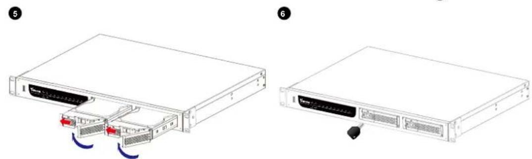
- Open the drive tray bezel as shown below and remove the drive tray.
- Install hard disks to the disk trays by securing it with the supplied four screws.
- Open the bezel of the drive tray as shown below and insert your hard disk(s) into the disk bays.
- Use the supplied bezel key to lock the drive trays in place to prevent unauthorized access.
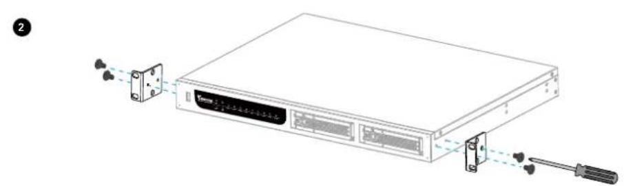
natural_image
Diagram of a server rack with two connectors and a screwdriver inserted, showing no text or symbols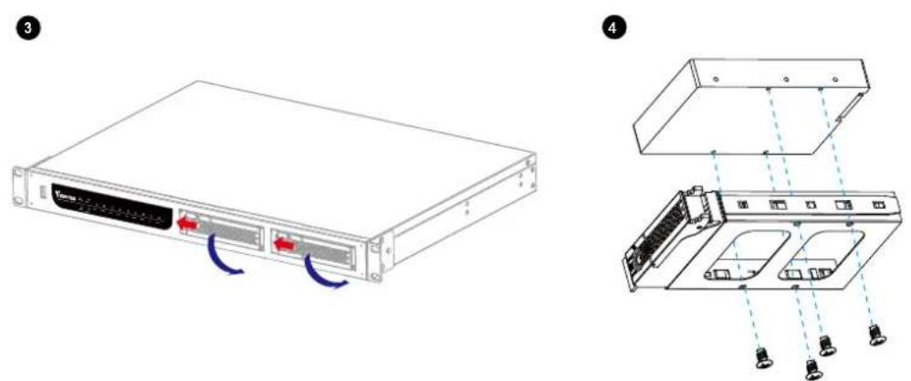
natural_image
Two views of a server rack unit showing internal components and cable connections (no text or symbols)NOTE
▶ Please remember to format the hard disks before starting recording. Please refer to Storage on page 48.
Network deployment
Device Connection
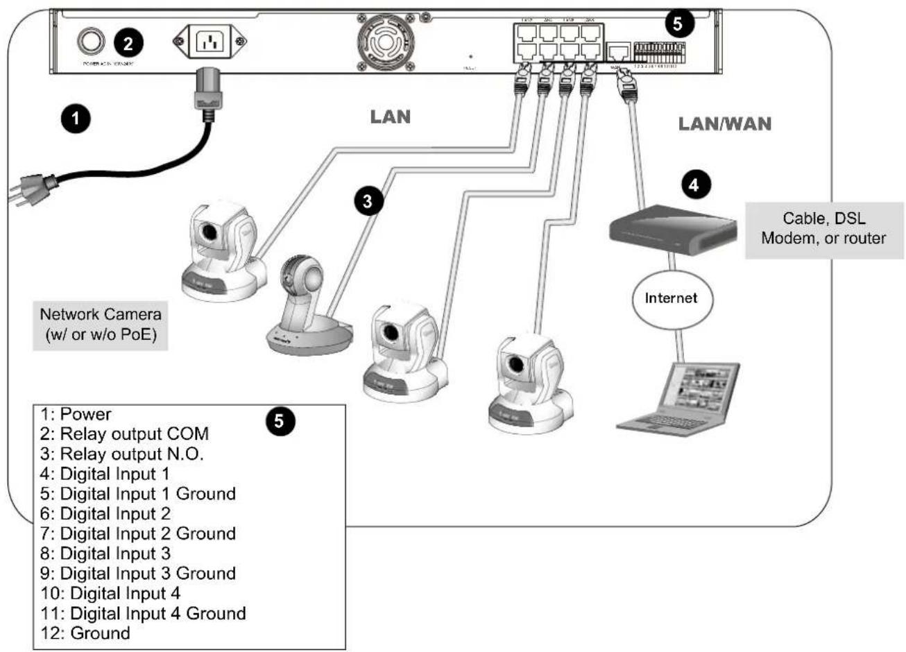
- Connect the supplied power cable from the NR8201/8301 to a power outlet.
- Press the power button to power up.
- Connect network cameras to NR8201/8301 LAN ports.
Because NR8201/8301 supports PoE, if the Network Camera is PoE-compliant (802.3af), an Ethernet cable transmits both power and data.
- 4-1. If your local network does not have a DHCP server, you may temporarily connect a PC to an NVR's LAN port for initial setup. The NVR comes with a default IP, 192.168.100.1. You may access the NVR server using this IP, and then manually assign an IP to the NVR WAN port.
4-2. If your local network has a DHCP server, connect the WAN port to your local network, and use the IW2 utility to find the NVR server IP. You may then access the NVR server by entering the discovered IP in the address field of a web browser.
- If you have external devices such as sensors and alarms, make connections from general I/O terminal block.
Install the IW2 Utility
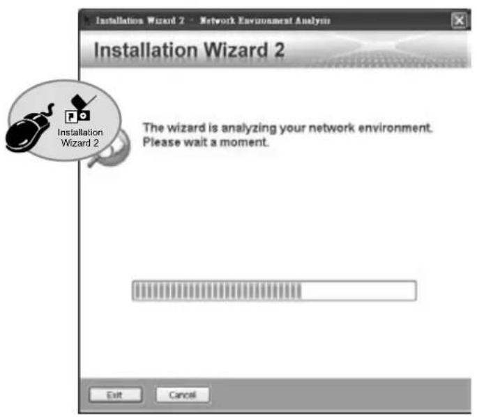
If your network environment is DHCP, you can use VIVOTEK Installation Wizard 2 (IW2) to discover the IP address for the WAN port.
(1) Install "Installation Wizard 2" from the Software Utility directory on the software CD.
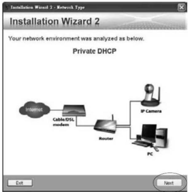
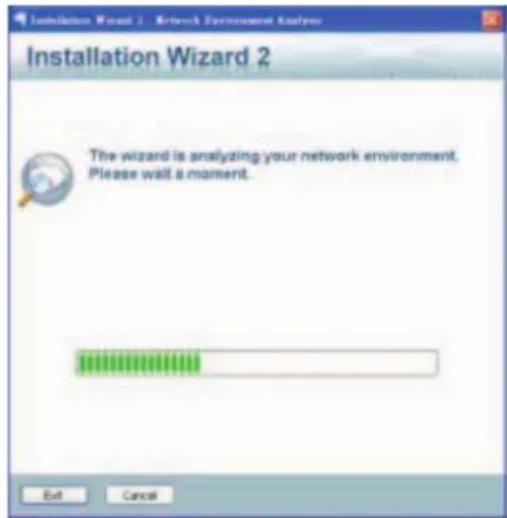
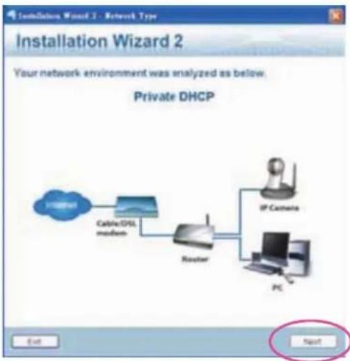
(2) The program will conduct an analysis of your network environment. After your network is analyzed, please click on the "Next" button to continue the program.
(3). The program will search for VIVOTEK network devices on the same LAN.
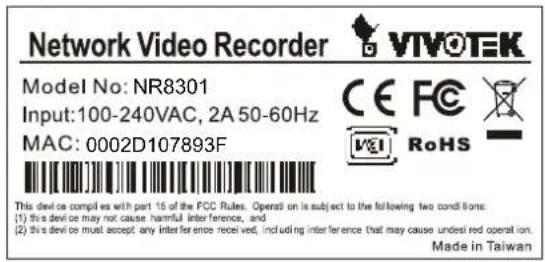
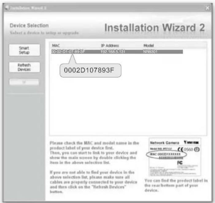
(4). After a brief search, the main install window will prompt. Double-click on the listed NVR and check if its MAC address matches that printed on the product label. A web browser console will be established.
flowchart
graph LR
    A["Internet"] --> B["Cable/DSL modem"]
    B --> C["Router"]
    C --> D["IP Camera"]
    C --> E["PC"]
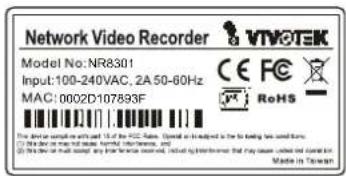
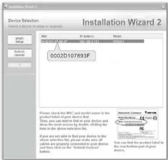
Supported & Unsupported Connections
- You can connect a management PC to the NVR's WAN port for management and monitoring. All cameras should be connected to the 10/100BaseT "LAN" ports which reside on a different subnet from the WAN port.
IMPORTANT!
Please configure the IP addresses for the "LAN" and "WAN" ports into different class C subnets, e.g., 192.168.100.xxx for LAN and 192.168.4.104 for WAN. Make sure they are not configured into the same subnet.
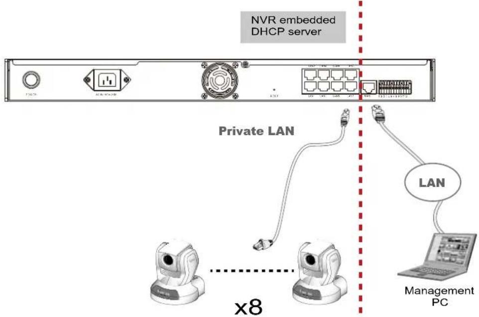
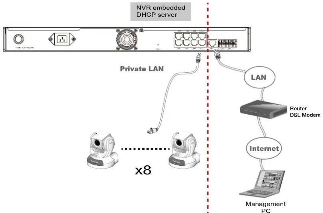
- A remote PC can access the NVR via an Internet connection to the NVR's WAN port. All cameras should be connected to the 10/100BaseT "LAN" ports.
flowchart
graph TD
    A["NVR embedded DHCP server"] --> B["Private LAN"]
    B --> C["LAN"]
    C --> D["Router DSL Modem"]
    D --> E["Internet"]
    E --> F["Management PC"]
    style A fill:#f9f,stroke:#333
    style B fill:#ccf,stroke:#333
    style C fill:#cfc,stroke:#333
    style D fill:#fcc,stroke:#333
    style E fill:#cff,stroke:#333
    style F fill:#ffc,stroke:#333
- If you use a "LAN" port to connect a management PC and that PC resides on a DHCP-enabled subnet, configuration conflicts will occur. Therefore, the "LAN" ports should always be used to connect PoE or non-PoE network cameras. The NVR will detect whether a camera is PoE-compliant and will not supply power to a non-PoE camera.
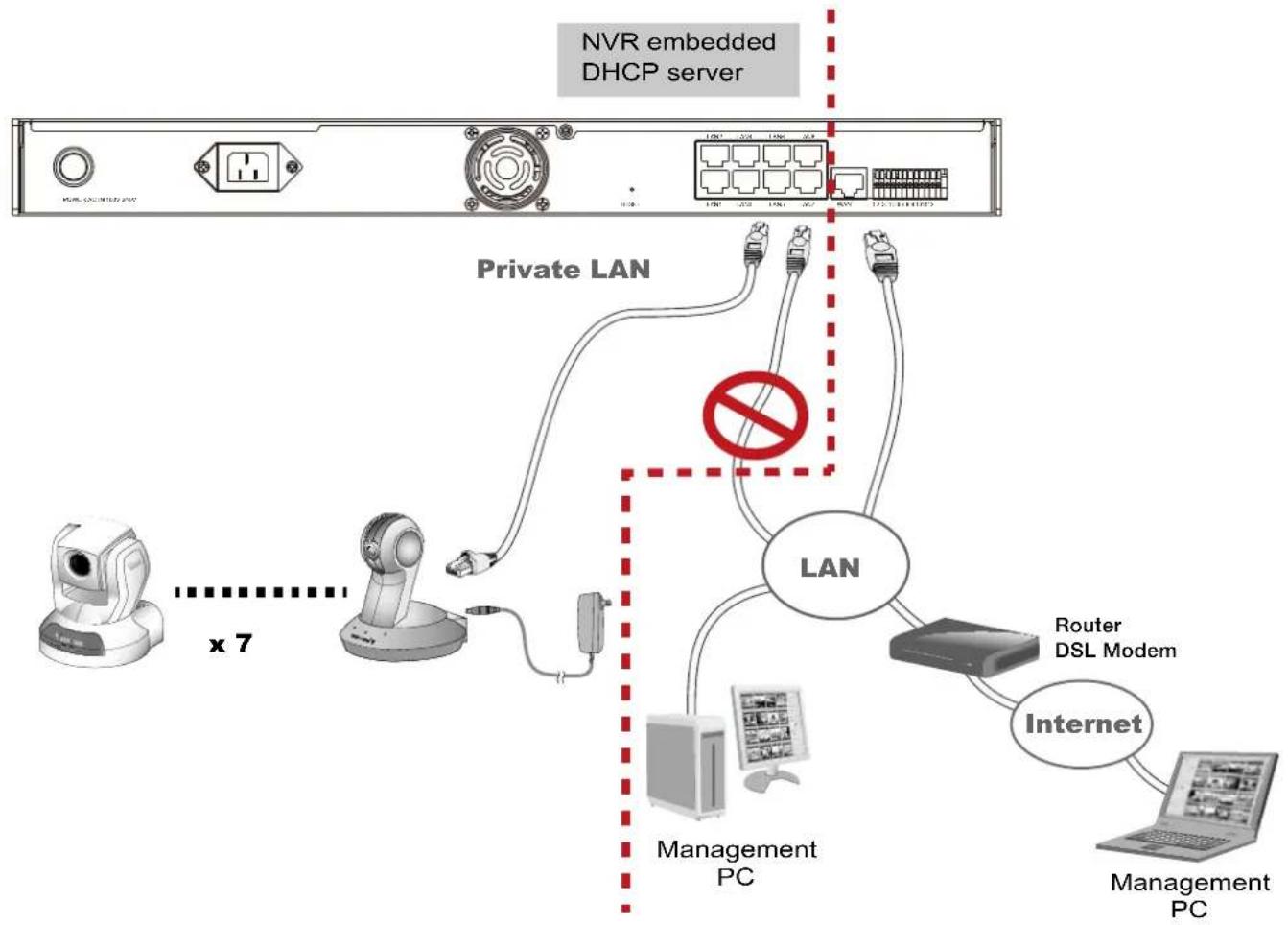
flowchart
graph TD
    A["NVR embedded DHCP server"] --> B["Private LAN"]
    B --> C["LAN"]
    C --> D["Router DSL Modem"]
    C --> E["Internet"]
    C --> F["Management PC"]
    C --> G["Management PC"]
    B --> H["x 7"]
    style B stroke:#ff0000,stroke-width:2px
    style C stroke:#000,stroke-width:2px
    style D stroke:#000,stroke-width:2px
    style E stroke:#000,stroke-width:2px
    style F stroke:#000,stroke-width:2px
    style G stroke:#000,stroke-width:2px
Getting Started
Please follow the steps below to link your computer to NR8201/8301 for the first time:
- Connect your computer to NR8201/8301 (LAN port) using an Ethernet cable.
- Setup your computer in DHCP mode.
a. Click Start > My Network Places > View network connections.
b. Right-click on Local Area Connection, and then click Properties.
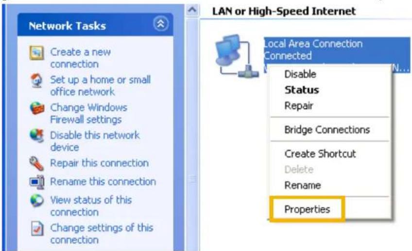
c. Select Internet Protocol (TCP/IP), and then click Properties.
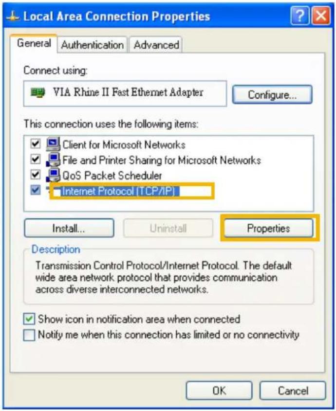
d. Select "Obtain an IP address automatically" and "Obtain DNS server address automatically" as below. Then click OK to enable your settings.
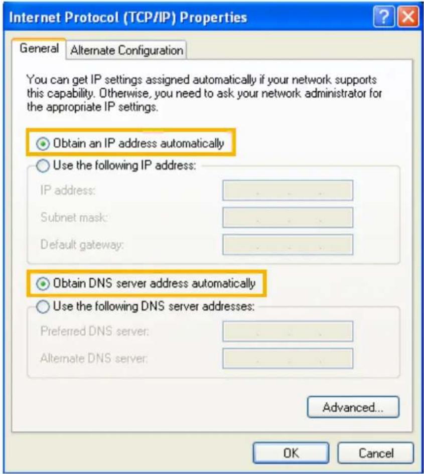
- Then NR8201/8301 will serve as a router and automatically assign an IP address to your computer.
Set up NR8201/8301 in LAN
To setup NR8201/8301 for the first time if your local network does not have a DHCP server, please connect to one of the NVR's LAN ports (to utilize NVR's onboard DHCP server). Set up your computer's network setting in DHCP mode (see page 13), and then directly enter the default IP for NR8201/8301 (http://192.168.100.1) in the address field of an IE browser. A web console with the NVR will be displayed and you can proceed with detailed configuration.
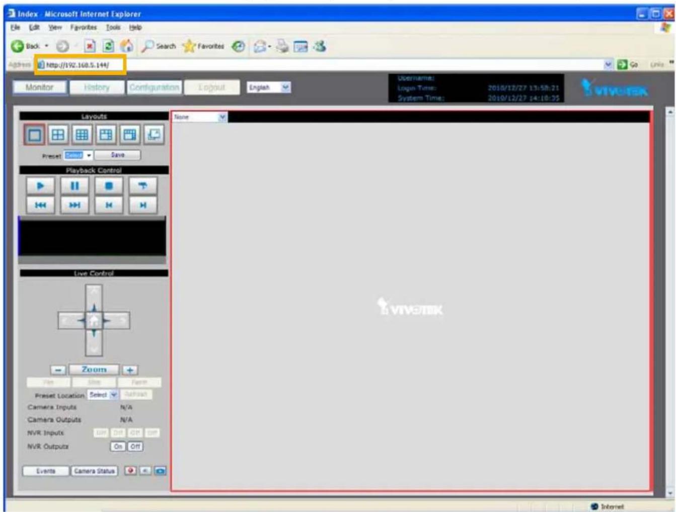
LAN Settings Configuration
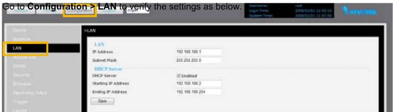
Network Settings Configuration
If you want to access the Network Video Recorder over the Internet, please go to Configuration > Network to assign a WAN IP address (public IP) for NR8201/8301. There are three ways to get an IP address: Private DHCP (Dynamic IP), Static IP address, and PPPoE (DSL).
Internet connection with private DHCP (dynamic IP)
Choose this connection type to automatically obtain a dynamic IP address assigned by a DHCP server. Please follow the steps below to verify the settings:
- Go to Configuration > Network. The Network page provides configurations for the WAN port. Click Get IP address automatically.
- Click Save to enable the settings.
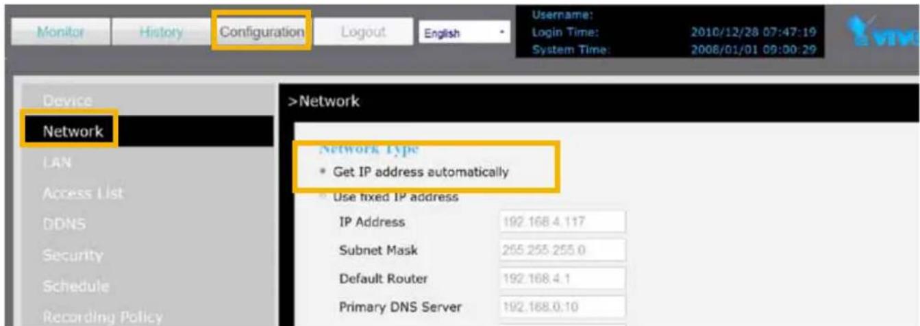
- If your computer is in the same domain with the WAN IP address, then you can use VIVOTEK Installation Wizard 2 (IW2) to search for the Network Video Recorder easily. Please follow the steps below to run IW2:
a. Install the IW2 under the Software Utility directory from the software CD. Double-click the IW2 shortcut on your desktop to launch the program.
b. The program will conduct analysis on your network environment. After your network environment is analyzed, please click Next to continue the program.
flowchart
graph LR
    A["Internet"] --> B["Cable/RTL medium"]
    B --> C["Router"]
    C --> D["IP Camera"]
    C --> E["PC"]
    F["Next"] --> G["End"]
c. The program will start searching for all VIVOTEK devices in the same LAN.
d. After searching, the main installer window will pop up. Click on the MAC and model name which match the product label to connect to the Network Video Recorder.
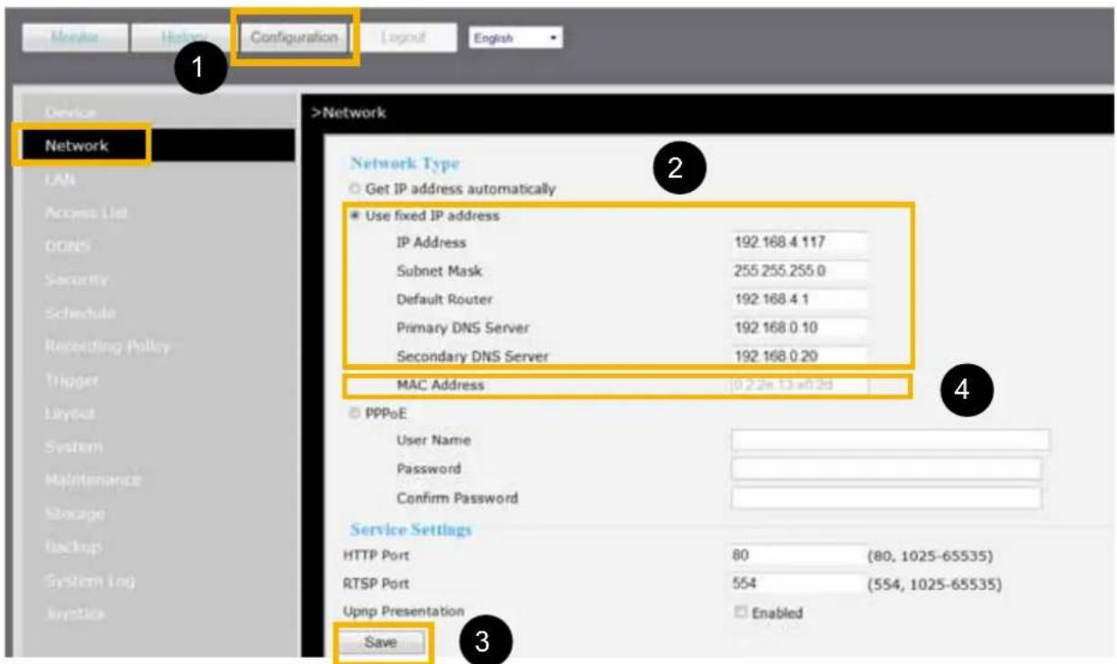
Internet connection with static IP
Choose this connection type if you want to use a static IP for the Network Video Recorder. Please follow the steps below to change the settings:
- Go to Configuration > Network. Click Use fixed IP address.
- Enter the static IP, Subnet Mask, Default Router, Primary DNS Server, and Secondary DNS Server provided by your ISP.
- Click Save to enable the settings.
- The MAC address will be shown when selecting fixed IP address.
Internet connection via PPPoE (Point-to-Point over Ethernet)
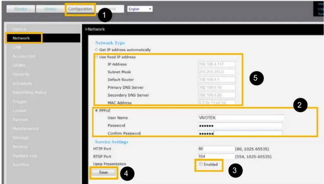
Choose this connection type if you wish to connect to the Internet via a DSL Line. Please follow the steps below to setup:
- Go to Configuration > Network. Click PPPoE.
- Enter the User Name and Password provided by your ISP.
- Enable the Upnp protocol by selecting the Upnp presentation if you require to apply it.
- Click Save to enable the settings.
- The IP Address, Subnet Mask, Default Router, Primary DNS Server, MAC address will automatically show up in the above blanks.
NOTE
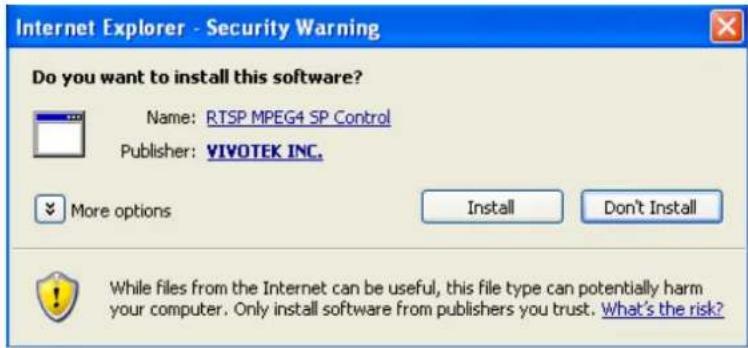
▶ When attempting link to NR8201/8301 for the first time with the web browser, a message will pop up to remind you of installing required plug-in or software first.
If you receive a message saying that your Internet Explorer® security settings prohibit installing Active X® components, please enable your Active X® Controls for your browser. 1. Click Tools > Internet Options > Security > Custom level... on the tool bar of the Internet browser.
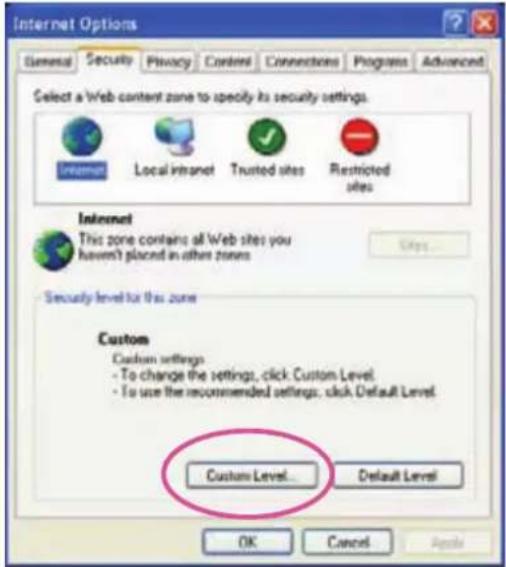
- Look for Download signed ActiveX® controls; select Enable or Prompt. Click OK.
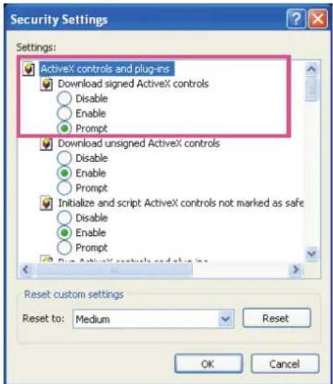
- Refresh your web browser, and then install the Active X ^ . Follow the instructions to finish installation.
Home Page
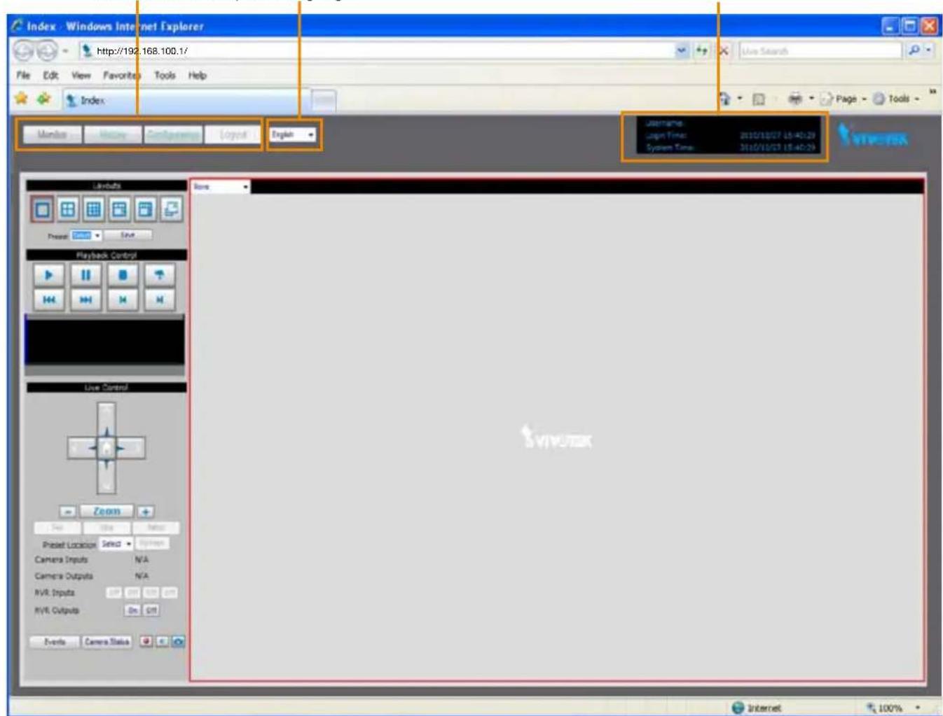
Following is the user interface of the home page. It is composed of the following sections.
Main menu Status panelLanguage
Main menu
There are four buttons for you to click to open the page:
Monitor: Click this button to open the monitoring page. This page is for you to see the live video or playback the recorded data.
History: Click this button to open the History page. This page is for you to search and playback recorded data in a specific range of time.
Configuration: Click this button to open the Configuration page. This page is for you to configure the settings of the network video recorder. It is suggesting to apply a password for the Network Video Recorder, so that only the authorized user can configure the settings. Please refer to page 22 for detailed information.
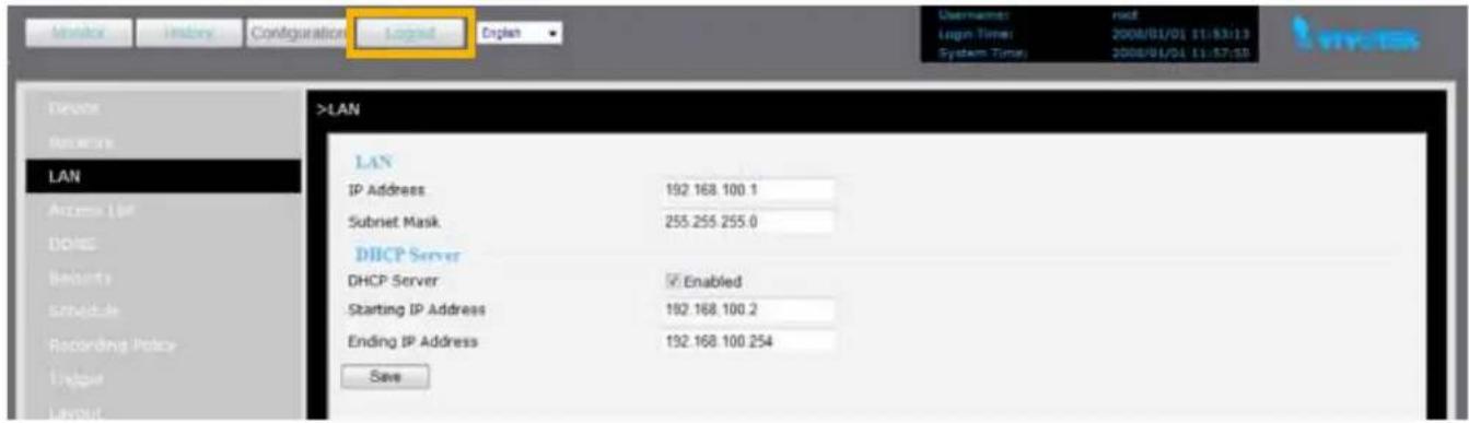
Logout: Click this button to logout the home page. This button will be enabled if you set up a root password in the Security page. Please refer to page 33 for detailed information.
Language
Click the drop-down list to choose a language for the user interface. Language options are available in: English, 繁體中文,簡体中文,日本語,ançais, Español, Deutsch, Português, Italiano.
Status panel
Username:
Login Time: 2010/12/28 07:47:19
System Time: 2010/12/28 07:48:14
User Name (default: root)
Login Time (yyyy-mm-dd hh:mm:ss)
Current Time (yyyy-mm-dd hh:mm:ss)
NOTE
The Username will be blank if you have not setup a password in the Security page. Please refer to page 33 for detailed information.
Depending on user's privilege of the user account, the access to the configuration page may be restricted. For more information about user's privilege, please refer to Manage Privilege on page 34.
Configuration
This page contains several sub-pages: "Device", "Network", "LAN", "Access list", "DDNS", "Security", "Schedule", "Recording Policy", "Trigger", "Layout", "System", "Maintenance", "Storage", "Backup", "System Log", and "Joystick". Each sub-page in the left menu will be explained in the following sections.
Device
This page allows user to add a new device or modify an inserted device. NR8201 supports simultaneous 4-CH video recording, and 8-CH video recording using NR8301.
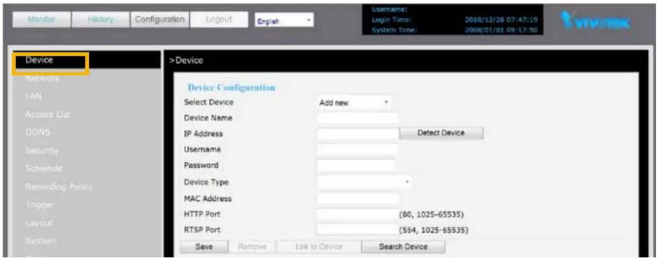
The following is the support list of NR8201 and NR8301. If the camera you wish to add is not on the list, you may choose “unknown” from the list, or you may download the newest firmware updated with the new models.
| 8000 series 7000 series 6000 series | ||
| IP8161 IP7135 / 7137 IP6112/ 22 | ||
| IP8330 IP7130/ 31/ 32/ 33/ 34/ 38/ 39 IP6117/ 27 | ||
| IP8332 IP7142 PZ6112/ 22 | ||
| IP8151/51P IP7151/ 52/ 53/ 54 PZ6114/ 24 | ||
| IP8162/62P | IP7160/ 61 | FD6111V/ 21V |
| FD8133 | IP7251/ 7330/ 7361 FD6112V/ 22V | |
| FD8134 | IZ7151 | SD6112V/ 22V |
| FD8161 | PT7135/ 37 | |
| FD8361 | PZ7151/ 52 | |
| SD81x1 | PZ7111/ 21/ 12/ 31/ 32 | |
| FD7131/ 32/ 41 | ||
| SD7151/ 73x3 | ||
| VS7100 | ||
Auto search by device installer or manually install in LAN
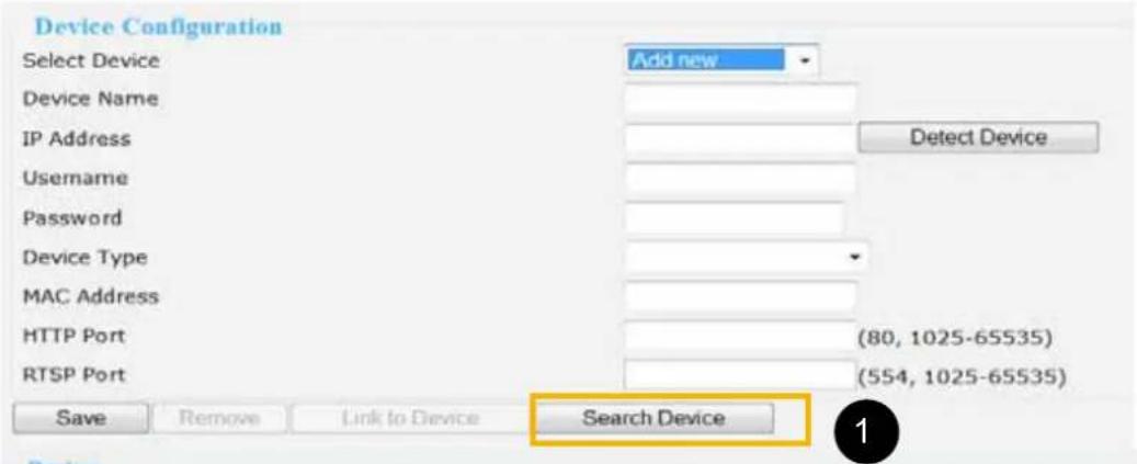
If your devices are linked to the LAN port of the Network Video Recorder, you can follow the steps below to add a new device:
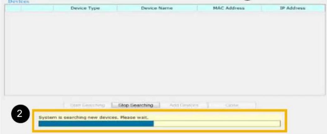
- Click Search Device. The searching results will be displayed in the following column. You can click Stop Searching if the linked devices are all displayed on the list.
- You may wait for a moment while the system is searching for the new devices.
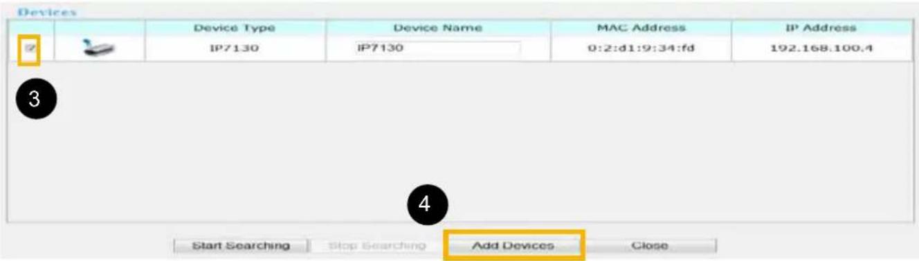
- Select a device to be inserted. Modify the Device Name if necessary.
- Click Add Devices to enable the settings.
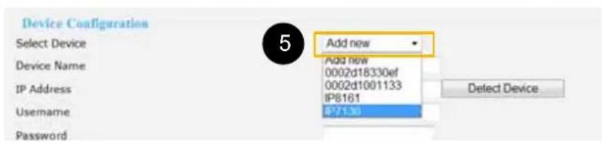
- Select Add new on the drop-down list, and click on the device which you would like to change the network settings.
- Enter the Username/Password if the device needs to do authentication. The Username/Password must be consistent to the camera's web server. Then, click on Save.
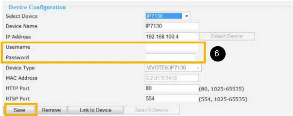
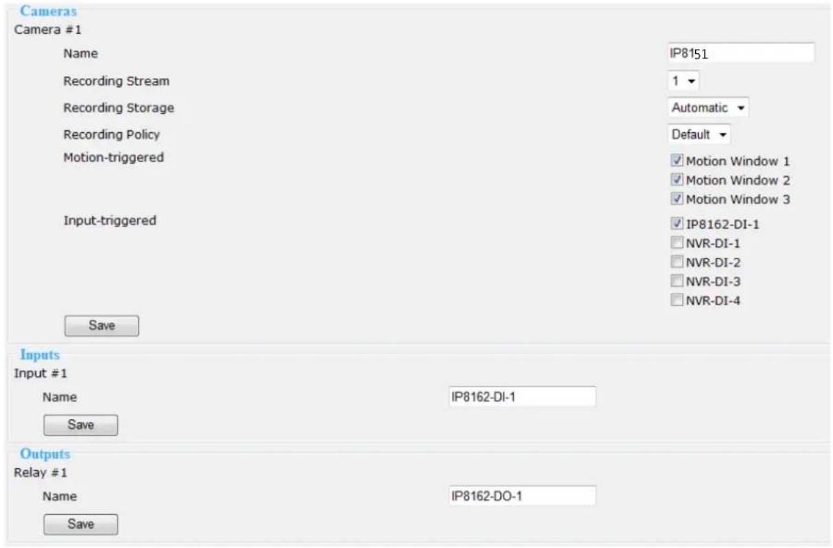
This section allows you to change the settings for the new device (camera).
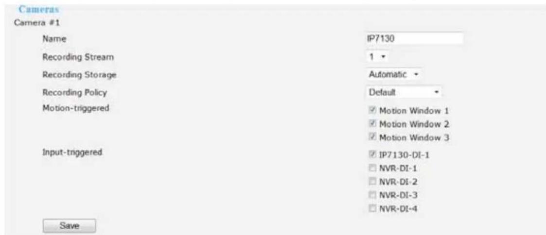
Name: Enter the Device Name.
Recording Stream: You may choose the stream for recording.
Recording Storage: You may select the storage for recording.
Recording Policy: Choose the recording policy. To know more details, please refer to page 37.
Motion-triggered: Choose the Motion Window. Noted that you need to set up motion windows on the configuration page of the camera first.
Input-triggered: Choose the digital input trigger source, and click Save to enable the effect.
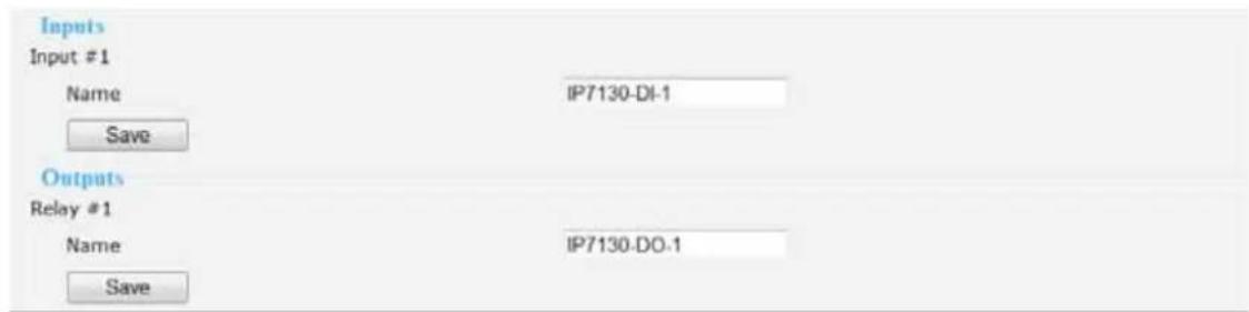
You may also change the names of the digital input and output source. Click on Save to enable the effect.
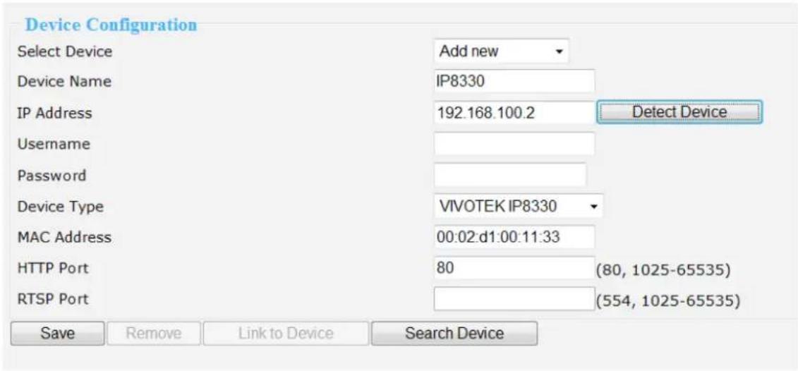
You can also manually install a new device in LAN.
Please follow the steps below:
- Select Add new on the drop-down list
- Enter IP Address.
- Enter the Username/Password if the device needs to do authentication.
- Click on Detect Device, the Device Type, MAC Address, and HTTP Port will show up in the blanks automatically.
- Click Save to enable the settings.
Manually install in WAN
When in WAN, you have to add a new device manually. Please follow the steps below:
- Select Add new on the drop-down list
- Enter IP Address.
- Enter the Username/Password if the device needs to do authentication.
- Click on Detect Device, the Device Type, MAC Address, and HTTP Port will show up in the blanks automatically.
- Click Save to enable the settings.
- If you wish to remove or link to the device, select the device and click "Remove" or "Link to Device" to remove or link to the device.
NOTE
▶ If you want to modify the settings of the device, select it on the drop-down list.
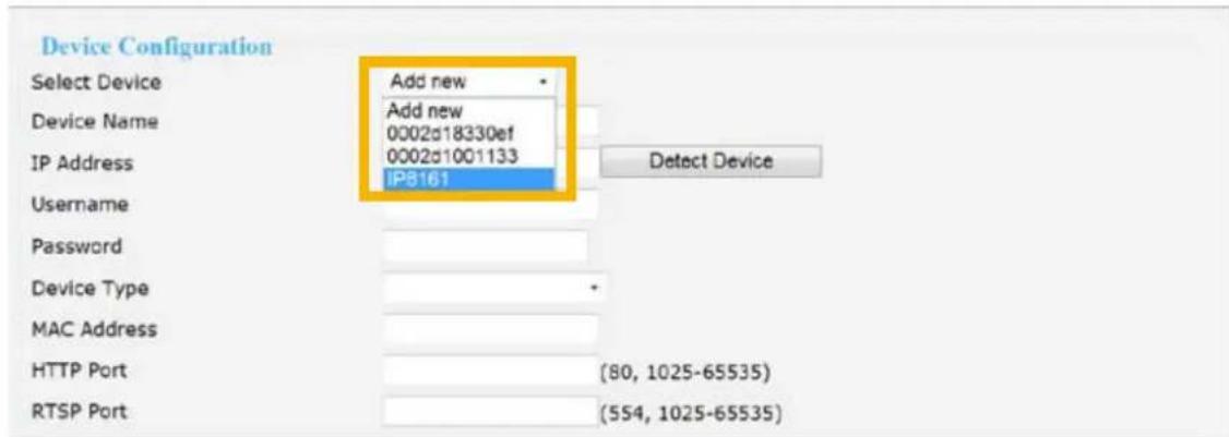
The device information will be displayed in the following blanks, and then you can modify the settings of the device. Please refer to page 24 for detailed information.
Network
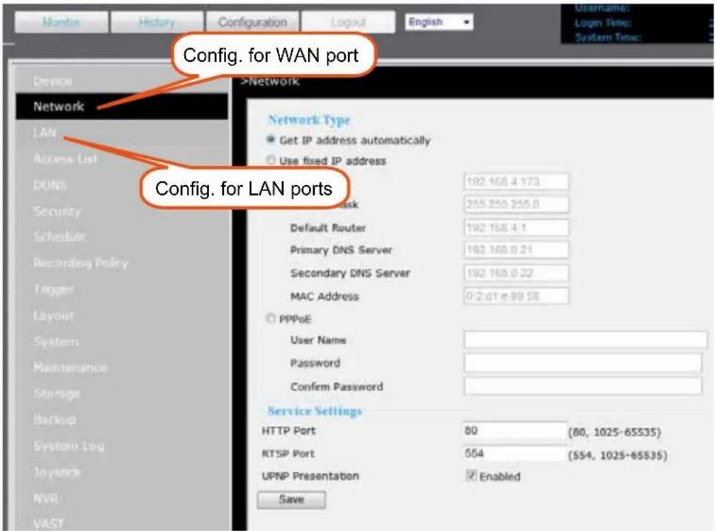
This page provides configurable options for the WAN port, the Gigabit Ethernet port on the rear panel for making the management access via LAN or remotely over Internet.
For making the initial connection, you can refer to page 16 for information. You may also configure a fixed IP address for the WAN port along with associated subnet mask, router, and DNS servers settings.
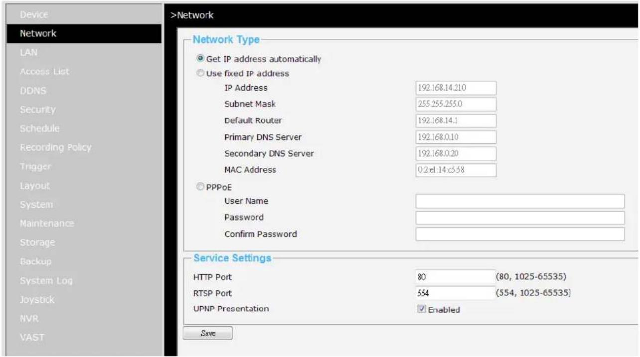
If you are using PPPoE for Internet connection, enter User Name and Passwords provided by your Internet Service Provider.
If you need an access from Internet via a router using the port forwarding methodology, you may need to open HTTP and RTSP ports on your network, and the UPnP Presentation. When done, click Save to reserve your settings.
LAN
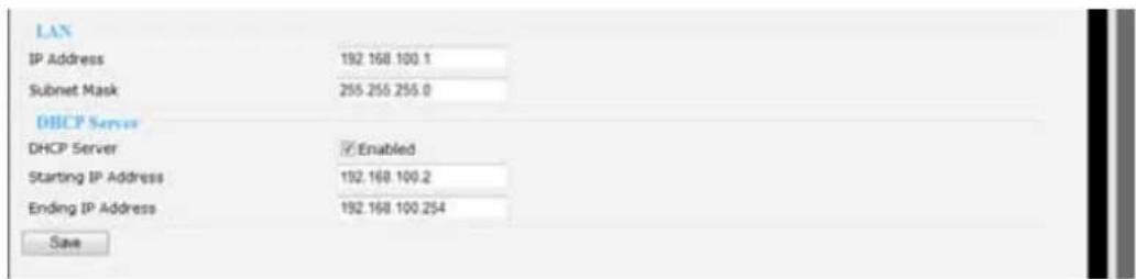
This page allows user to configure LAN configuration for the Network Video Recorder. It contains two columns: "LAN" and "DHCP Server."
LAN / DHCP Server
The NVR server comes with an embedded DHCP server for connecting 4 or 8 "LAN" ports to network cameras. This page allows Administrators to configure network configuration for those LAN ports. The configuration menu contains two columns: "LAN" and "DHCP Server." In LAN, the default IP Address for the NVR server is 192.168.100.1 (used only when using a LAN port for the initial configuration). The default Subnet Mask is 255.255.255.0.
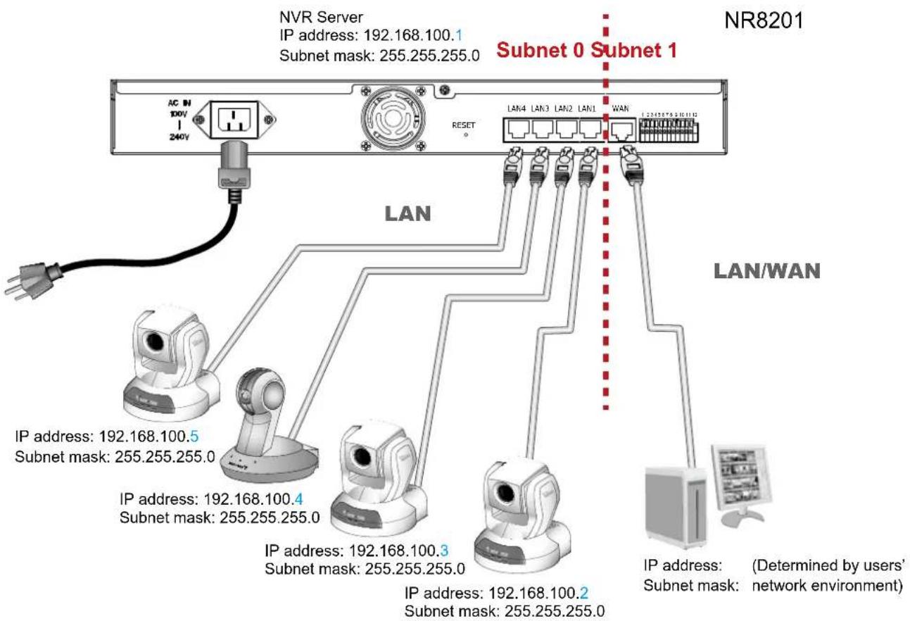
If you connect network cameras to NVR as diagrammed below, the embedded DHCP server will automatically assign IP addresses to the 4 (NR8201) and 8 (NR8301) cameras (192.168.100.2 \~ 192.168.100.254), while the NVR server itself takes up the first address.
NOTE
In order to comply with IEC 60950-1 regulations, DO NOT connect the LAN ports to other devices (such as a PC) unless for the initial setup. These LAN ports are designed for camera connections, and come with PoE power through the lines, which may impose unpredictable problems when connected to a non-PoE device. Although PoE detection circuits have been implemented with these ports, it is best to avoid the connections to devices other than PoE cameras.
▶ The LAN ports should be connected only to PoE networks without routing to the outside plants.
WARNING!
The "Network" configuration page provides configurable options for the NVR's WAN port. The "LAN" configuration page provides network configuration options for the 4 or 8 LAN ports, and usually you do not need to change its configuration.
▶ Please do not confuse the two different configuration pages and create identical settings on these two pages. Doing so will produce network problems.
Access list
This page allows the user to setup the access permission for the Network Video Recorder by identifying the IP address of the client's PC Following columns are the setup options of access permissions: "Allowed List", "Denied List".
Allowed list / Denied list
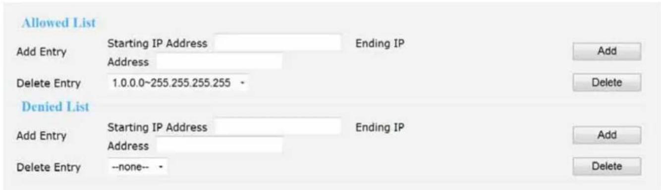
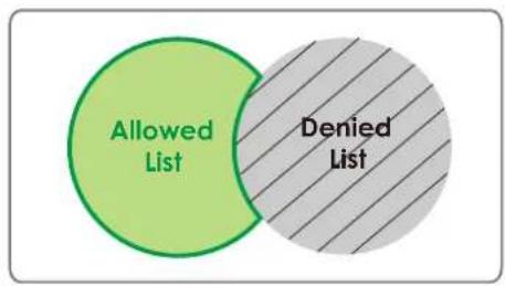
There are two lists for permission control: Allowed list and Denied list. Only the IP on the allowed list is permitted to access to the Network Video Recorder.
- In the Allowed list or Denied list column, type in the starting IP address and ending address in the blank space on the allowed list and the denied list columns. A number of total 10 IP entries for both lists can be configured.
- Click Add to take effect.
NOTE
For example, when the range of allowed list is set from 1.1.1.0 to 192.255.255.255 and the range of denied list is set from 1.1.1.0 to 170.255.255.255, Only users' IP located between 171.0.0.0 and 192.255.255.255 can access the Network Video Recorder.
Delete allowed list / Delete denied list
- In the Delete allowed list or Delete denied list, select a list from the drop-down list.
- To delete the entry, please select the entry from the list and click delete to take effect.
DDNS
This page allows user to configure dynamic domain name service for the Network Video Recorder. DDNS (Dynamic domain name service) is a service that allows your network video recorder to be assigned with a fixed dynamic IP address with a domain name.
DDNS Settings
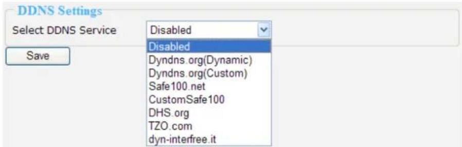
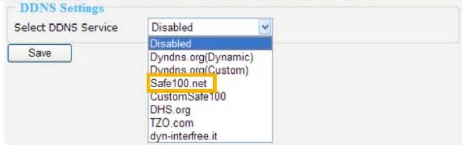
Select DDNS Service: Select a DDNS provider from the Provider drop-down list.
VIVOTEK offers Safe100.net, a free dynamic domain name service to VIVOTEK customers. It is recommended that you register with the Safe100.net to access the Network Video Recorder from the Internet. Additionally, we offer other DDNS providers, such as Dyndns.org, DHS.org, TZO.com, dyn-interfree.it.
Note that to utilize this feature, please apply a dynamic domain account first.
■ Safe100.net
- Select www.safe100.net on the Provider drop-down list.
- Click I Accept when you agree with the terms of the Service Agreement.
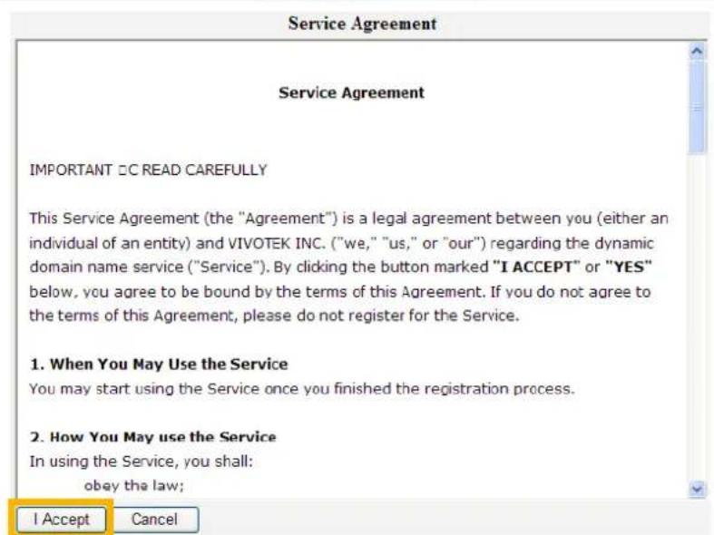
- In the Register column, fill in the Host name, Email, Key and Confirm Key and then click Register. You will receive a "Self registration E-mail" which records your account information.
![Register Host Name VIVOTEK [*.safe100.net] Email wtk@vivotek.com Key ••••• Forget Key Repeat Key ••••• Register](/content/2026/05/944716/images/2b9ec7ab0ce809adbc8992a5d189fd539d2f51e584eb88635d292acd3051d1ae.jpg)
- Back to the DDNS settings window, enter your account information and then click Save to enable the settings.
![DDNS Settings Select DDNS Service Safe100.net Host Name VIVOTEK [*.safe100.net] Email wtk@vivotek.com Key ••••• Save](/content/2026/05/944716/images/abc57fe6145e1a12c260a76d1adf0d9f3c0e41c1c42e0a9440917aaaeed10bac.jpg)
Forget key: Click this button if you forget the key of Safe100.net. Your account information will be sent to your e-mail address.
Please refer to the following links to apply a dynamic domain account when selecting other DDNS providers:
■ Dyndns.org (Dynamic) / Dyndns.org (Custom): visit http://www.dyndns.com/
■ TZO.com: visit http://www.tzo.com/
■ DHS.org: visit http://www.dhs.org/
■ dyn-interfree.it: visit http://dyn-interfree.it/
Security
This page allows Administrator to enable password protection and create multiple user accounts for the Network Video Recorder. It is composed of the following three columns: "Root Password", "Manage Privilege", and "Manage User".
Root Password
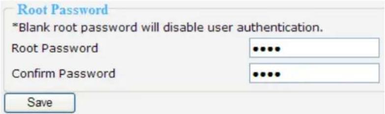
If you want to add more accounts in Manage User column, please apply a password for the "root" account first. Please follow the steps below to set up root password:
- Enter the password identically in both text boxes.
- Click Save to enable password protection.
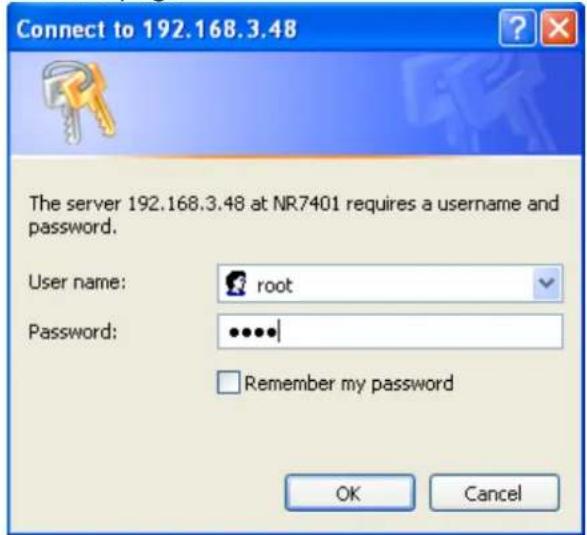
- The following window will automatically pop up for you to login. Enter the administrator username as "root", which is permanent and can not be changed. Enter the root password you've just setup, and then click Login to link to the page.
- The Logout button on the Main Menu will be enabled after you set up a root password.
Manage Privilege
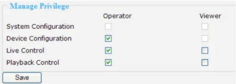
In this section, you can modify the manage privilege of operators or viewers. Check or uncheck the item, and then click Save to take effect.
Following is the privilege list of different user accounts:
| User privileges Administrator Operator Viewer | ||
| System Configuration O X X | ||
| Device Configuration O O X | ||
| Live Control (Monitor page) O O O | ||
| Playback Control (History page) O O O |
NOTE
The user privileges of an administrator are always enabled and unchangeable.
▶ Operator and Viewer don't have the permission to the Configuration page.
Manage User
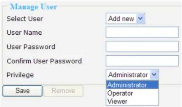
■ Administrator can add up to twenty user accounts.
- Enter the new user's name and password.
- Select the Privilege for new user account. Click Save to take effect.
■ Here you also can change user's privilege or delete user accounts.
- Select an account on the drop-down list.
- Make necessary changes and then click Save or Remove to take effect.
NOTE
▶ NR8201/8301 allows up to 10 users to login to the webpage simultaneously.
Schedule
This page allows Administrator to add a new Recording Schedule or modify an existing Schedule for the Network Video Recorder. You can configure up to 16 recording schedules based on a weekly basis.
By default setting, all inserted device are assigned to the default recording schedule (always). Therefore, once you insert a device to the network video recorder, it will begin to record live video continuously.
![Schedule Configuration Select Schedule Add new ▼ Name Schedule Entries Add Entry Begin Sunday 00:00 [hh:mm] End Sunday 00:00 [hh:mm] Delete Entry --none-- ▼ Schedule Display Sunday Monday Tuesday Wednesday Thursday Friday Saturday](/content/2026/05/944716/images/5acf50d23590667dde1b7b70dffb43a015d02497c6357955c7c6fcd90f77929c.jpg)
■ Please follow the steps below to add a new recording schedule:
- Enter a descriptive name for the new schedule.
- Select a day and enter a time frame (in the format of 24hr).
- Click Add to take effect. The new recording schedule will show up in the Schedule Display column. You can add more than one time frames under the same schedule name.
Following is an example of recording schedule (Mon.\~Fri. 09:00\~12:00).
![Schedule Configuration Select Schedule schedule 1 Name schedule 1 1 2 3 Schedule Entries Add Entry Begin Sunday 00:00 [hh:mm] End Sunday 00:00 [hh:mm] Delete Entry Monday 09:00~Monday 12:00 Add Delete Schedule Display Sunday Monday Tuesday Wednesday Thursday Friday Saturday](/content/2026/05/944716/images/6fc7b00565bb3feaf3055bec2d2587d5658619652651678499b7f11fdbe5ea72.jpg)
■ The new recording schedule will show up on the Recording Mode as below. Notice that to enable the schedule, you may set up a recording policy first. Please refer to page 37 to continue the setting.
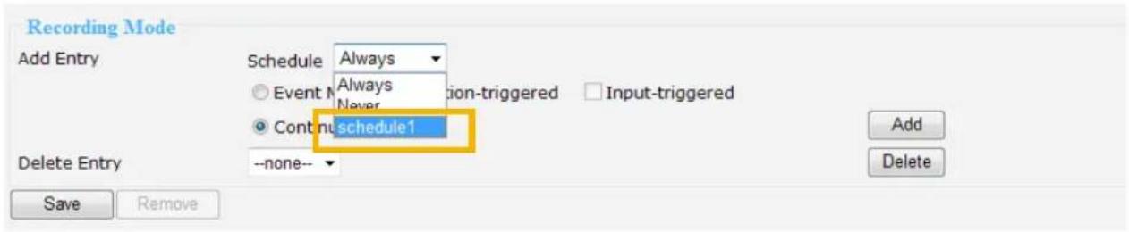
The new recording schedule will also show up on the Trigger Configuration as below. Click Trigger on the left Menu. Then you can select Always, Never, or schedule1 as your schedule for event trigger.
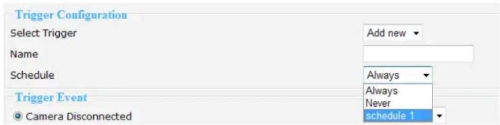
■ If you want to delete a recording schedule, select it on the drop-down list (Select Schedule) and then click Remove to delete it.
■ If you want to delete a time frame, select it on the drop-down list (Delete Entry) and then click Delete.
Recording Policy
This page allows user to set up recording policy for linked cameras. By default setting, all inserted cameras are assigned to the default recording schedule (always), default recording type (continuous mode), and default recording policy (save continuous recording for 30 days).
Therefore, once you insert a camera to the Network Video Recorder, it begins to record live video continuously and save "30 days" of recorded videos. You may go to History page to retrieve the videos.
For example:
The user adds a VIVOTEK IP8162 camera to NR8201/8301. Following pictures shows the default settings:
■ Configuration > Device

■ Configuration > Recording Policy

■ Recorded video clips on History page.
| Start Time | Length | Size(KB) | Recording | |
| 2011/01/26 16:41:20 | 02'38" | 151756 | Continuous | |
| 2011/01/26 16:43:59 | 02'38" | 151992 | Continuous | |
| 2011/01/26 16:46:37 | 02'38" | 152791 | Continuous | |
| 2011/01/26 16:49:16 | 02'38" | 153566 | Continuous | |
| 2011/01/26 16:51:55 | 02'38" | 152692 | Continuous | |
| 2011/01/26 16:54:34 | 02'38" | 152487 | Continuous | |
| 2011/01/26 16:57:12 | 02'38" | 152925 | Continuous | |
| 2011/01/26 16:59:51 | 00'42" | 40440 | Continuous |
For detailed information about the History page, please refer to page 57.
This page allows Administrator to add/modify a new Recording Policy and Recording Mode. There are 4 types of Recording Policy for the user to configure properly.
■ Please configure the following items to add a new Recording Policy/Recording Mode:
Recording Policy
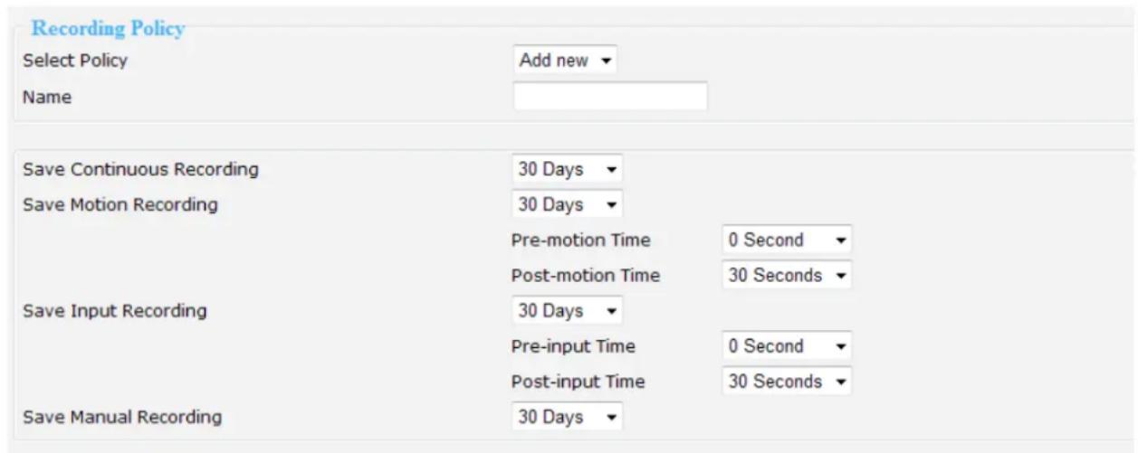
Select Policy: Select Add new.
Name: Enter a descriptive name for the new recording policy.
Save Continuous Recording: Select an option of the time period (1 Hour, 1 Day, 1 Week, 2 Weeks, 30 Days, 90 Days, 180 days, or 365 days) as the time of the continuous recorded videos.
Save Motion Recording: Select an option of the time period (1 Hour, 1 Day, 1 Week, 2 Weeks, 30 Days, 90 Days, 180 days, or 365 days) as the time of the motion-triggered recorded videos.
■ Pre-motion Time: Select an option of the time period (0 Seconds, 10 Seconds, 30 Seconds, 1 Minute, or 5 Minutes) as pre-motion time. Pre-motion records the video in a pre-set time period before the event and merges the recorded event into one combined video.
■ Post-motion Time: Select an option of the time period (30 Seconds, 1 Minute, or 5 Minutes) post-motion time. Post-motion records the video in a post-set time period after the event and merges the recorded event into one combined video.
Save Input Recording: Select an option of the time period (1 Hour, 1 Day, 1 Week, 2 Weeks, 30 Days, 90 Days, 180 days, or 365 days) as the time of the input-triggered recorded videos.
■ Pre-input Time: Select an option of the time period (0 Seconds, 10 Seconds, 30 Seconds, 1 Minute, or 5 Minutes) as pre-input time.
■ Post-input Time: Select an option of the time period (30 Seconds, 1 Minute, or 5 Minutes) as post-input time.
Save Manual Recording: Select an option of the time period (1 Hour, 1 Day, 1 Week, 2 Weeks, 30 Days, 90 Days, 180 days, or 365 days) as the time of the manual recorded videos.
Recording Mode
Add Entry: Select the event mode or continuous mode to apply to the schedule as an entry.
■ Event Mode: Select to apply the motion-triggered type, input-triggered type or both types of the event mode to the schedule.
■ Continuous Mode: Select to apply the continuous mode to the schedule.

Click Add, the new recording mode will show up in the Delete Entry drop-down list. To select a recording mode, please select it in the Delete Entry drop-down list, and click Delete. When finished, click Save to take effect.
If you wish to remove the recording policy, go to Recording policy section and select the given recording policy first. Then, click Remove. See below.
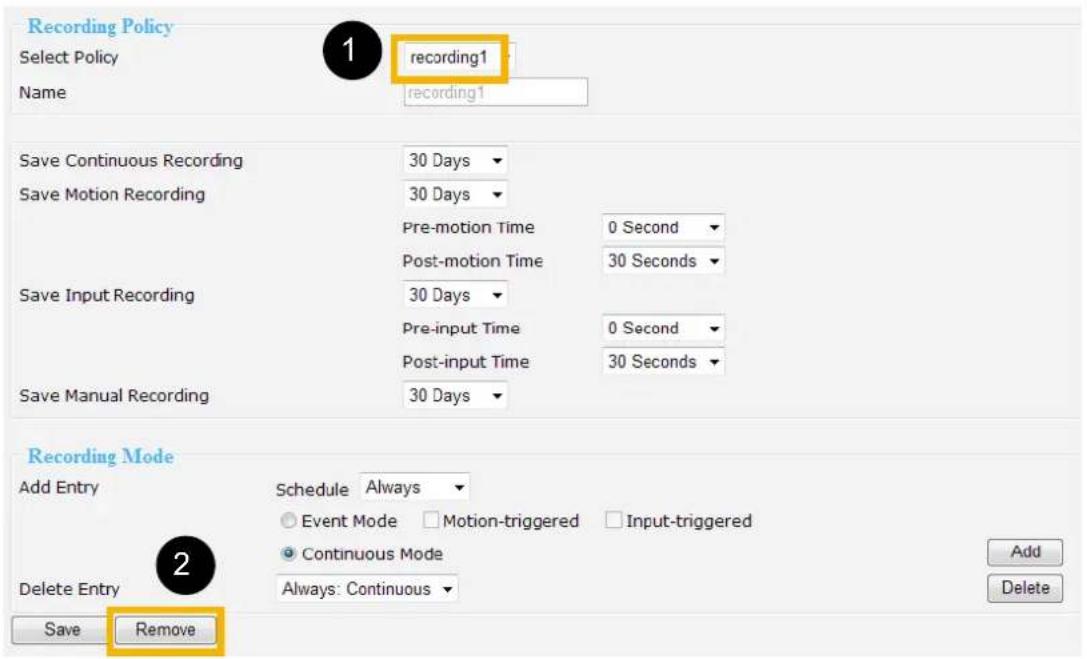
The new recording policy will show up on the device information as below. Click Device on the left Menu. Then you can select Default or recording1 as your recording policy.
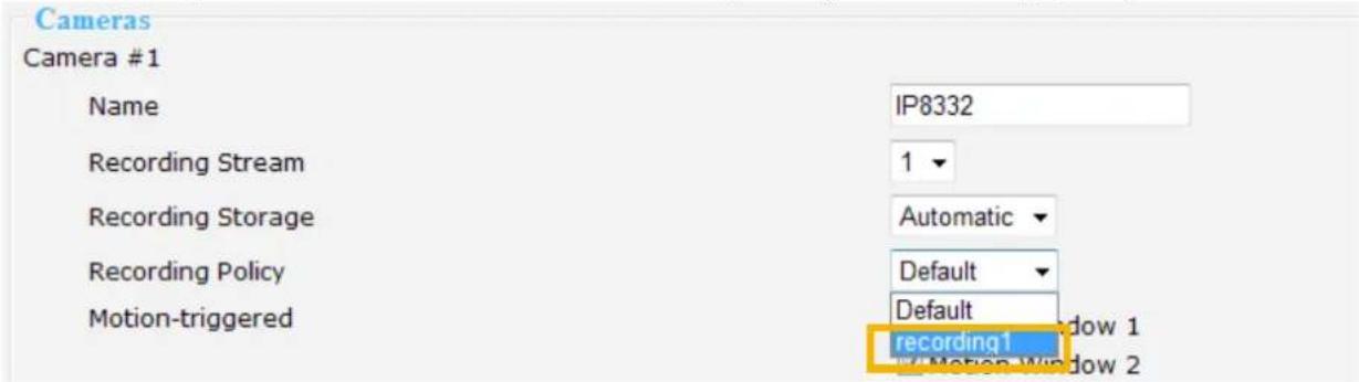
Trigger
This page allows Administrator to configure the Network Video Recorder to react in response to particular triggered events. A typical reaction is that when a motion is detected by the network camera, the Network Video Recorder sends buffered images to a FTP server or E-mail address as notifications. Sixteen sets of events are available for triggering.
In the following illustration, an event can be triggered by many sources, such as motion detection or external alarm (digital input devices). When an event is triggered, you can specify what kind of action should be performed. You can assign the Network Video Recorder to send notifications to your e-mail address or FTP site.
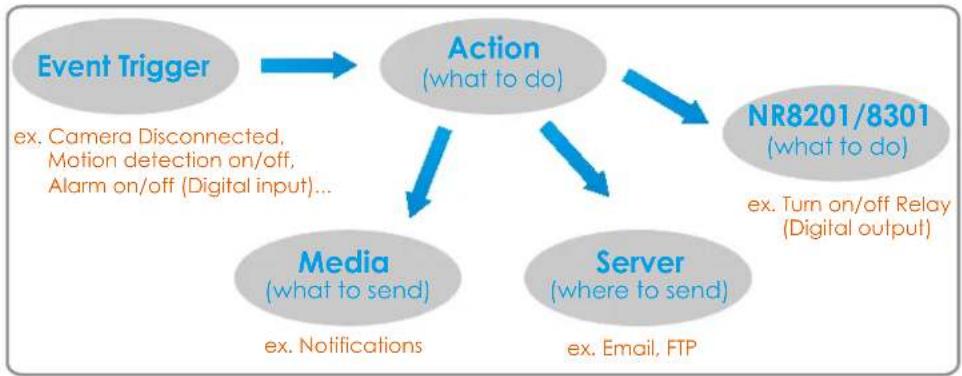
flowchart
graph TD
    A["Event Trigger"] --> B["Action (what to do)"]
    B --> C["Media (what to send)"]
    B --> D["Server (where to send)"]
    C -->|ex. Notifications| B
    D -->|ex. Email, FTP| B
    E["NR8201/8301 (what to do)"] --> B
    F["ex. Turn on/off Relay (Digital output)"] --> B
    G["ex. Camera Disconnected, Motion detection on/off, Alarm on/off (Digital input)"] --> B
■ Please configure the following items to add a new trigger type of event.
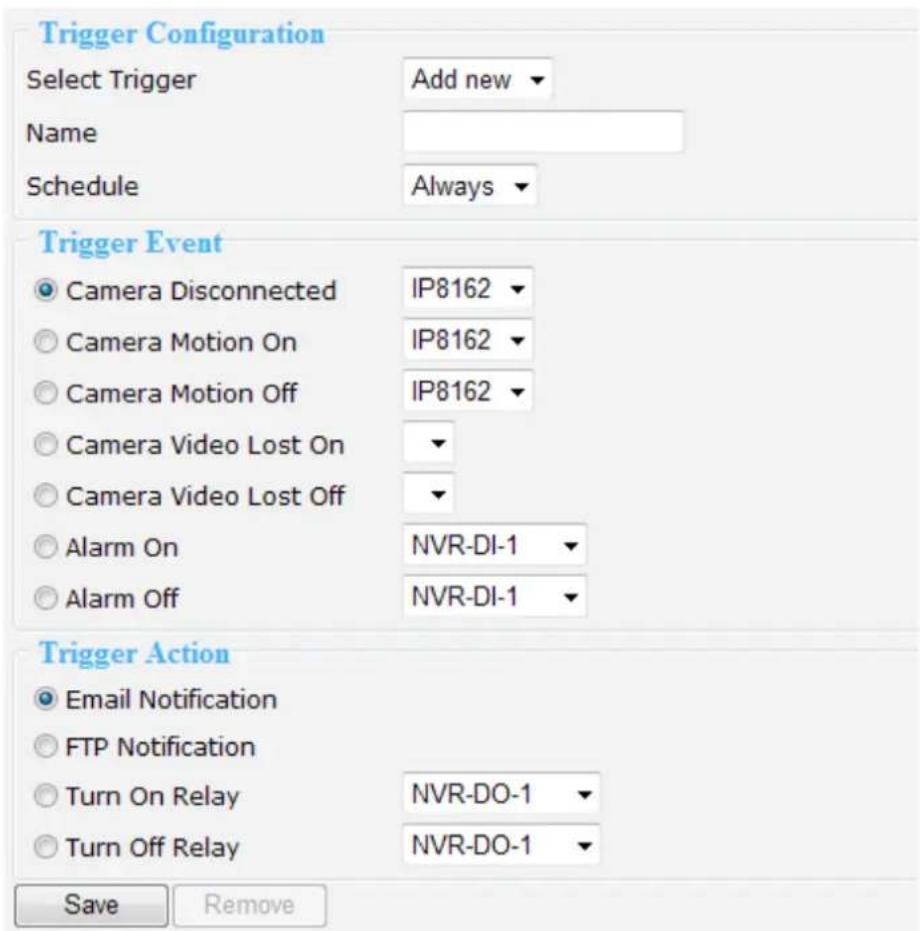
Trigger Configuration
Select Trigger: Select Add new.
Name: Enter a descriptive name for the new event trigger.
Schedule: Select a recording schedule on the drop-down list (Always, Never, or pre-set recording schedule).
Trigger Event
1. From linked devices
Select one of the following event source, and then select a linked device.
Camera Disconnected: Linked Device is disconnected.
Camera Motion On: Motion detection window is triggered on linked Device.
Camera Motion Off: Motion detection window is stopped on linked Device.
Camera Video Lost On: Video lost happens on linked Device (ex. VIVOTEK video server VS7100).
Camera Video Lost Off: Video lost ends on linked Device (ex. VIVOTEK video server VS7100).
Alarm On: Alarm (external digital input) is triggered on linked Device. This function will only be enabled on the devices with DI function.
Alarm Off: Alarm (external digital input) is off on linked Device. This function will only be enabled on the devices with DI function.
2. From the network video recorder
Select one of the following source; and then select a digital input.
Alarm On: Alarm (external digital input NVR-D1-1 \~ NVR-D1-4) is triggered on the network video recorder.
Alarm Off: Alarm (external digital input NVR-D1-1 \~ NVR-D1-4) is off on the network video recorder.
NOTE
▶ You can modify the Name and priority of digital inputs on the network video recorder. Please refer to Digital Input on page 46 for detailed information.
Trigger Action
To plot an event trigger, please select one of a following action so that the Network Video Recorder will know what action should be performed when a trigger is activated.
1. Actions of the system
Please click System on the left main menu to configure E-mail server or FTP server settings first.
Please refer to page 45 for detailed configuration.
Email Notification: Send *.txt notification to user's e-mail address.
FTP Notification: Send *.txt notification to user's FTP site.
2. Actions of the linked devices
Turn On Relay: Turn on Relay (digital output) on linked device. This function will only be enabled on the devices with DO function.
Turn Off Relay: Turn off Relay (digital output) on linked device. This function will only be enabled on the devices with DO function.
3. Actions of the network video recorder
Turn On Relay: Turn on Relay (digital output do0) on the network video recorder.
Turn Off Relay: Turn off Relay (digital output do0) on the network video recorder.
NOTE
▶ You can modify the Name of digital outputs on the network video recorder. Please refer to Digital Input on page 46 for detailed information.
▶ E-mail & FTP notification
- E-mail format:
| Event Type Camera disconnected Motion | on Motion off Alarm | on Alarm off | |||
| Title | Event notification from Device Y: Camera disconnected | Event notification from Device Y: motion_on | Event notification from Device Y: motion_off | Event notification from Device Y: alarm_on | Event notification from Device Y: alarm_off |
| Content Device Y is disconnected | Device Y motion # X on | Device Y motion # X off | Device Y DI Device Y-DI-X on | Device Y DI Device Y-DI-X on | |
| With Snapshot (jpg.) | No Yes Yes Yes Yes | ||||
- FTP format
| Event Type | Camera disconnected Motion on Motion off | ||
| Snapshot | No snapshot | motion on_Z_MAC address_date&time_random number.jpg | motion off_Z_MAC address_date&time_random number.jpg |
| Event Type | Alarm on | Alarm off | |
| Snapshot | alarm on_Z_MAC address_date&time_random number.jpg | alarm off_Z_MAC address_date&time_random number.jpg | |
■ "Y" refers to the Device Name. For example, IP8162. (Y=8162)
■ "X" refers to the motion window number of the device in Motion on and Motion off notification, while it refers to digital input number in Alarm on and Alarm off notification.
For example, Camera IP8162 mortion #1 on (X=1)
Device IP8151 DI IP8151-DI-2 on (X=2)
■ "Z" refers to the motion window number of the device. Noted that Z number 0,1,2 indicates the motion window 1,2,3.
For example, motion_on_0_2d18332af00_20110214065122_371.jpg (Z=0, Z= motion window 1)
■ Date should be in YYYYMMDD_HHMMSS format.
For example: 20080509_122342_Motionon.jpg
▶ Only the event of the linked cameras will send snapshot notification.
Layout
This page allows Administrator to configure the customized layout styles for monitoring. The settings are composed of the following two columns: Layout Configuration, and Default Layout, of which allow you to add and edit the layout group by assigning the desired device (camera) to each viewing cell. Meanwhile, the setting will be synchronized to the monitoring page for a quick viewing.
Layout Configuration
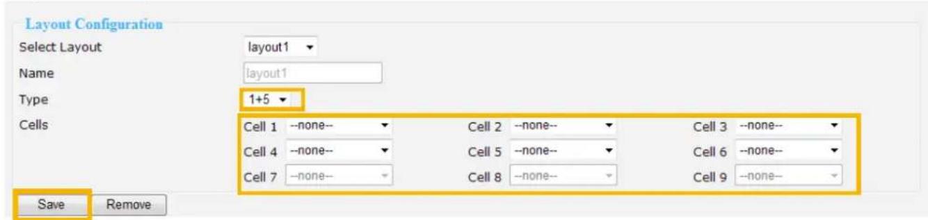
Select layout: Choose Add new.
Name: Enter a name for the new layout.
Type: Choose a desired type (1x1,2x2,3x3,1+5,1+7) for the display in live viewing window on the monitoring page. Noted that there are only two types of layout (1x1,2x2) supported in NR8201.
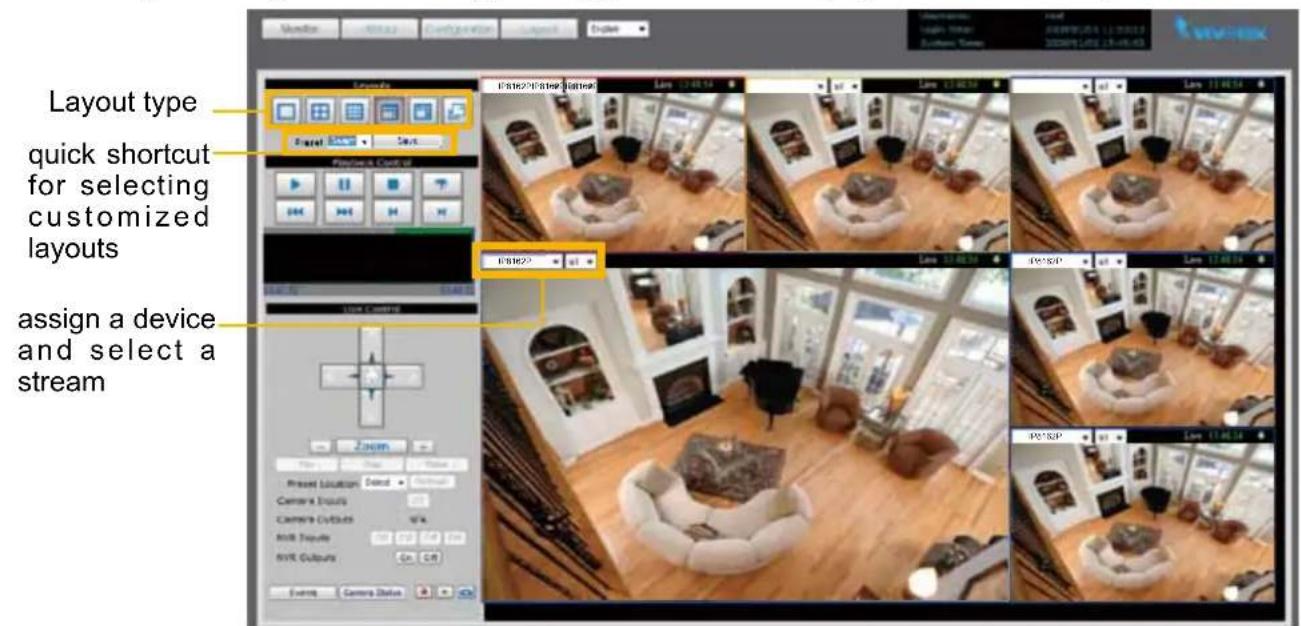
Cells: You can assign a device and select a stream of the assigned device for each cell. Noted that there are up to 4 cells for NR8201, and up to 9 cells for NR8301.
Save: Click Save to save the new layout.
Remove: Select the layout you want to remove, and click Remove.
Once the layout configuration is done, you may go to the monitor page to confirm the layouts.
Default Layout

Select a layout you've set in Layout Configuration column, and click Save Default to enable the setting.
System
This page allows Administrator to configure the system settings for the Network Video Recorder, Formed with the following columns; system, system time, E-mail server, FTP server, digital inputs, digital output and VAST.
System
System
Host Name
Device Automatic Installation
Snapshot and Download Path
NR8301 for Jimmy
Enabled
Save
Save
Save
Host Name: Add a host name for the system identification.
Device Automatic Installation: Check Enable, and the system will automatically detect the plugged-in camera. Then click Save.
Snapshot and Download Path: The path defines where the system stores the snapshot of both live monitoring and playback, and the downloaded video from history. It has to be setup before executing the snapshot and download functions.
System Time
System Time
- Keep current date and time
Sync with computer time
© Manual
Automatic
2011/02/14 10:45:09
2011/02/14 11:47:28
2011/02/14 [yyyy/mm/dd] 10:45:04 [hh:mm:ss]
Save
Select one of the following option as the system time displaying in the status panel on top right of the monitor page. Please refer to page 21 for detailed information.
Keep current date and time: Select this option to reserve the current date and time of the Network Video Recorder. The Network Video Recorder's internal real-time clock maintains the date and time even when the power of the system is turned off.
Sync with computer time: Select this option to synchronize the date and time of the Network Video Recorder with the local computer. The read-only date and time of the PC is displayed as updated.
Manual: The administrator can enter the date and time manually. Note that the date and time format are [yyyy/mm/dd] and [hh:mm:ss].
Automatic: The Network Time Protocol is a protocol serves synchronize computer clocks by periodically querying an NTP Server. Assign the IP address or domain name of the time-server.
E-mail Server
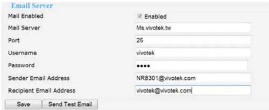
Mail Server: Enter the domain name or IP address of the e-mail server.
Port: The default mail server port is set to 25. You can manually set another port.
Username: Enter the user name of the e-mail account.
Password: Enter the password of the e-mail account.
Sender Email Address: Enter the e-mail address of the sender.
Recipient Email Address: Enter the e-mail address of the recipient.
When the setup is done, you may try to confirm the settings by clicking on Send test E-mail. Then, click Save to enable the settings.
FTP Server
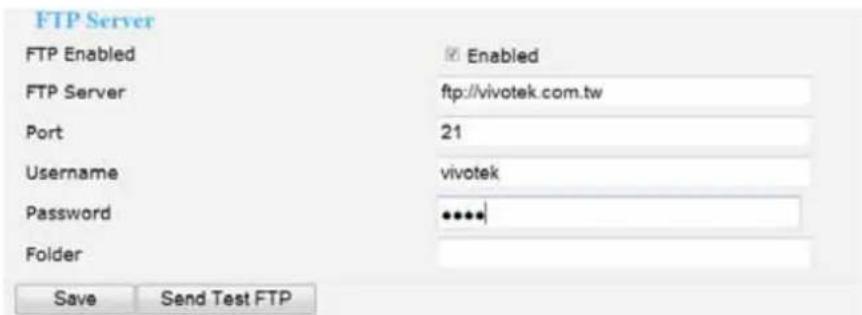
FTP Server: Enter the domain name or IP address of the FTP server.
Port: By default, the FTP server port is set to 21. It can also be assigned to another port number between 1025 and 65535.
Username: Enter the login name of the FTP account.
Password: Enter the password of the FTP account.
Folder: Enter an existing folder on FTP sever to place the media file.
When the setup is done, you may try to confirm the settings by clicking on Send test FTP. Then, click Save to enable the settings.
Digital Input
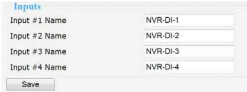
In the digital input section, you may modify the name of the external digital inputs.
Digital Output

In the digital output section, you may modify the name of the external digital output.
VAST
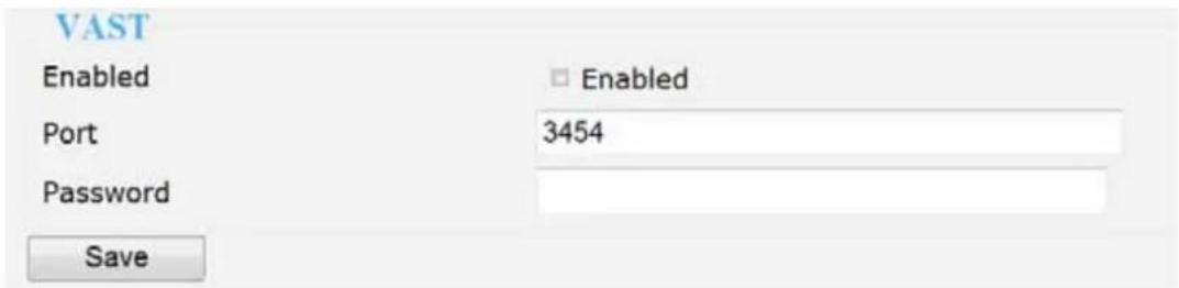
This section allows you to enable the service for VAST to connect to the NVR. The port is set to 3454 by default. It requires a password for authentication. Noted that the maximum live connection is 10, and the connection for VAST counts one live connection in the system.
Maintenance
This page allows Administrator to restore the Network Video Recorder to factory default, format hard disk, and upgrade firmware version, etc.
System
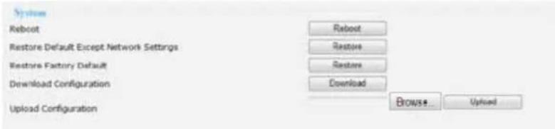
Reboot: This function allows you to restart the Network Video Recorder. It takes 1 \~ 2 minutes to complete the process. If the connection fails after rebooting, manually enter the IP address of the Network Video Recorder in the address field to resume the connection.
Restore Default Except Network Settings: This function allows you to restore to the factory default settings leaving the network settings unchanged. (WAN / LAN / Host name settings).
Restore Factory Default: This function allows you to restore to the factory default settings. Please note the camera list of device page will no longer exist. The recorded video will still remain and retrievable in history.
The process window will display when the reboot or restore is in processing.

Download Configuration: Click Download to save the configuration. Please note the configuration of NR8201 and NR8301 cannot be used for one the other.
Upload Configuration: Click Browse and specify the configuration file in your computer. Then click Upload to replaced the configuration with the uploaded file.
Firmware

This feature allows you to upgrade the firmware to your Network Video Recorder. Download a new firmware file from VIVOTEK website. The file is in .upt file format.
In this section, it shows the version and released time of the current firmware for verification. You may start to load the latest firmware to your computer, and then click Upgrade to start the process. Please note that do not power off NVR during the process. The NVR will reboot automatically when the upgrade is complete.

Storage
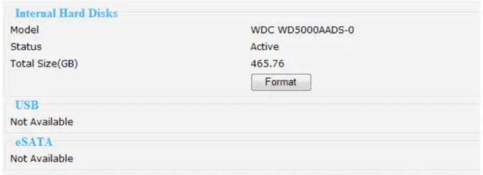
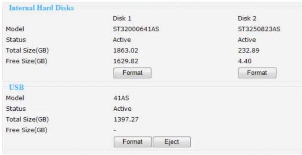
This column shows the information of your internal hard disk, USB, and eSATA. For the first time you install the hard disk, please format it before recording. In addition, if you want to delete all recorded data, you can click Format to clean the hard disk. The following message is displayed during the formatting process.
■NR8201
NR8301
RAID
The system is formatting hard disks now. Please wait.

NR8301 supports RAID 0, 1 as for storage management. You may choose to format the hard disks to RAID 0 or RAID 1. Once the RAID pattern is applied to the hard disks, the storage space will follow the RAID system. If you replace the hard disks, you can click Recover RAID button to recover the preset RAID system. If you want to disable the RAID mode, please format both of the hard disks.
NOTE
▶ Please remember to click Eject before removing the eSATA and USB device.

Backup
This function allows Administrator to backup the recorded data to the USB storage. Please remember to initialize the USB disk to EXT3 USB Storage file format for the first time.
Scheduled Backup
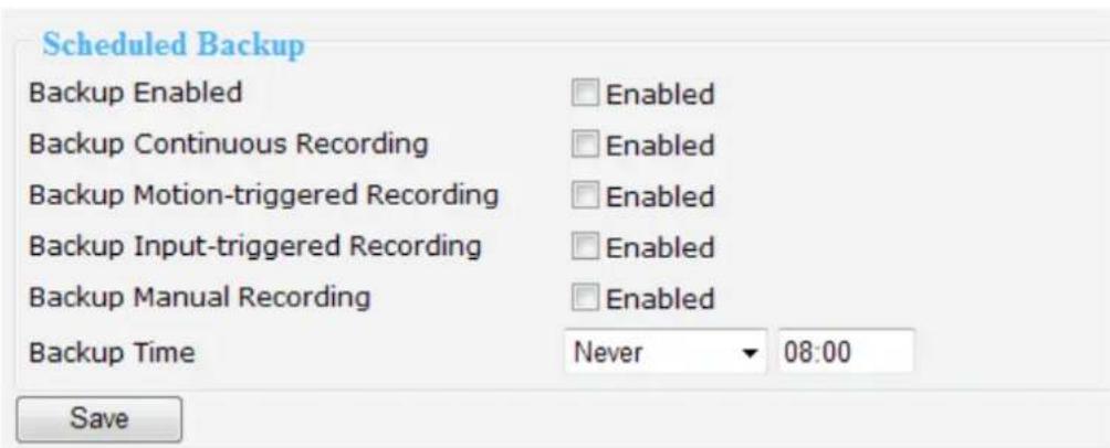
There are several options for you to narrow down the range of the data. First of all, it is necessary to enable backup, and then you may select the backup options individually or simultaneously. Next is pick up the backup date and time and then click Save to execute it.
Manually Backup
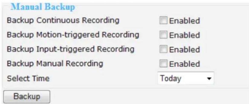
There are several options for you to narrow down the range of the data. First of all, it is necessary to enable backup, and then select the backup options individually or simultaneously. Next is pick up the backup date and time and then click save to execute it.
USB
| USB | |
| Model | USB DISK |
| Status | Uninitialized |
| Total Size(GB) | 0.48 |
| Free Size(GB) | - |
Your backup data will be stored in USB. Once you plug in the device, the system will display the current USB status as shown above.
System log
This column displays the system log in chronological order. The system log is stored in the Network Video Recorder's buffer area and will be overwritten when reaching a certain amount. Click Refresh, it will update the latest system log.
![- [2011/01/18 04:59:59 UTC][info:GSM]Camera IP8332 motion #2 off. [2011/01/18 04:59:59 UTC][info:GSM]Camera FD8161 motion #2 on. [2011/01/18 04:59:59 UTC][info:GSM]Camera FD8161 motion #3 on. [2011/01/18 04:59:59 UTC][info:GSM]Camera FD8161 motion #3 off. [2011/01/18 04:59:59 UTC][info:GSM]Camera FD8161 motion #2 off. [2011/01/18 05:00:00 UTC][info:GSM]Camera IP8332 motion #2 on. [2011/01/18 05:00:00 UTC][info:GSM]Camera IP8332 motion #2 off. [2011/01/18 05:00:01 UTC][info:GSM]Camera IP8332 motion #2 on. [2011/01/18 05:00:01 UTC][info:GSM]Camera IP8332 motion #2 off. [2011/01/18 05:00:02 UTC][info:GSM]Camera IP8332 motion #3 on. [2011/01/18 05:00:02 UTC][info:GSM]Camera IP8332 motion #3 off. [2011/01/18 05:00:04 UTC][info:GSM]Camera IP8332 motion #3 on. [2011/01/18 05:00:04 UTC][info:GSM]Camera IP8332 motion #3 off. [2011/01/18 05:01:22 UTC][info:GSM]Camera FD8161 pir on. [2011/01/18 05:01:23 UTC][info:GSM]Camera FD8161 pir off. [2011/01/18 05:01:23 UTC][info:GSM]Camera FD8161 pir on. [2011/01/18 05:01:23 UTC][info:GSM]Camera FD8161 pir off. [2011/01/18 05:01:37 UTC][info:GSM]Stop node scan. [2011/01/18 05:01:37 UTC][info:GSM]Start node scan on interface eth0. [2011/01/18 05:01:37 UTC][info:GSM]IP address 192.168.100.6 found at MAC Refresh](/content/2026/05/944716/images/3e6e8466f8e0683fc06baeefeffaaad050771d5217368bdb630ad936adce8c56.jpg)
Joystick
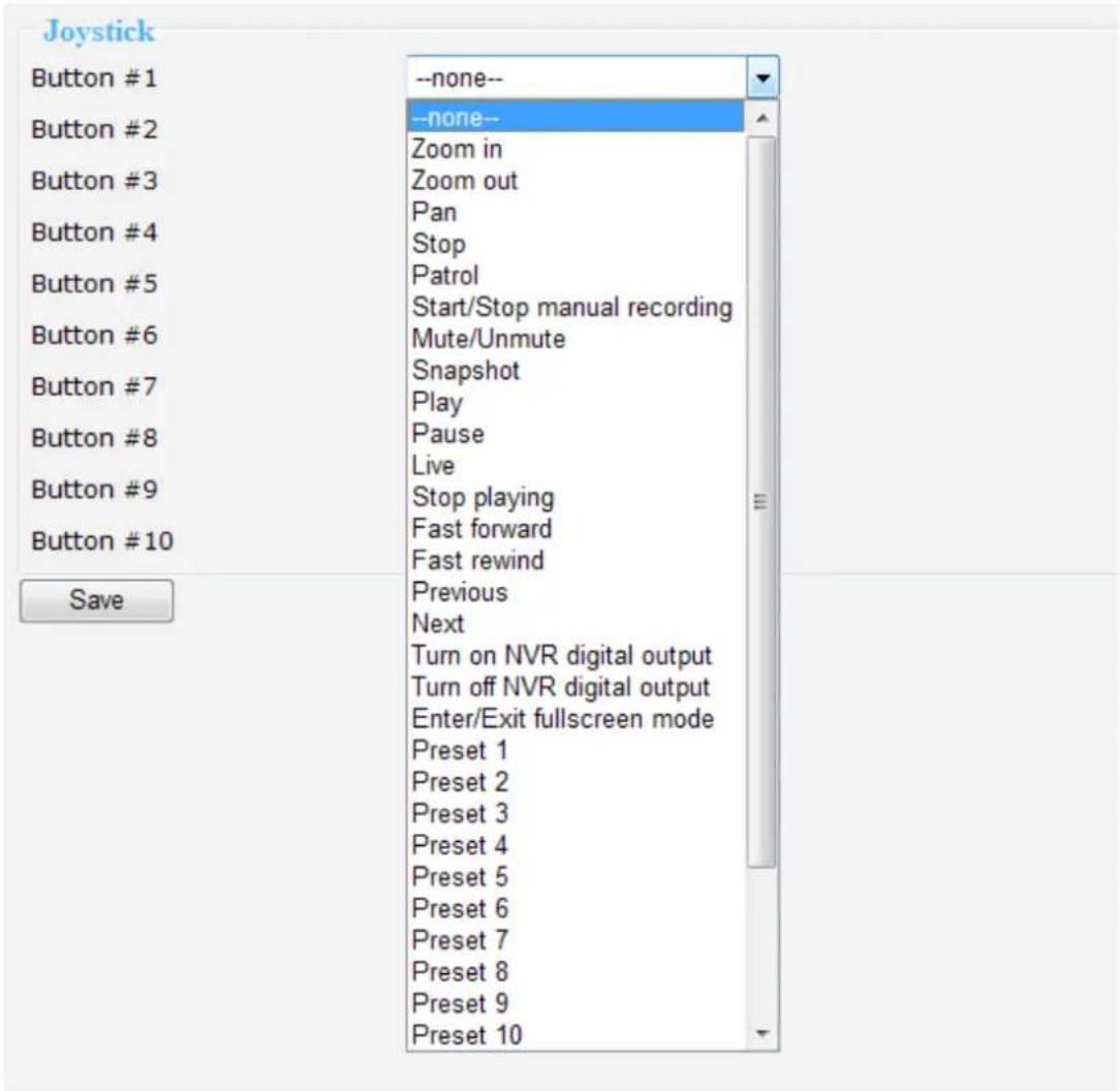
NR8201/8301 supports the use of VIVOTEK's joystick. You can control your PTZ cameras through it. It is simple as plugging it into the USB connector on the PC and refresh the NVR Configuration page. The joystick functional buttons support to be assigned with commands as zoom in/out, pan, stop, patrol, start/stop manual recording, mute/unmute, snapshot, play/pause, live, stop playing, fast forward/fast rewind, previous/next, turn on/turn off NVR digital output, enter/exit full screen mode, and preset 1 \~ 16. You can assign up to 10 commands to the 10 buttons of joystick for control. Click Save when the setup is complete.
Monitor
This page allows user to see the live view or playback recorded video from linked devices.
User Interface of Monitor Page
Click Monitor on the Main Menu, the user interface of Monitor page will be displayed.
■ Following is the Monitor page (NR8301) without connected cameras.
■ Following is the Monitor page (NR8301) without connected cameras.
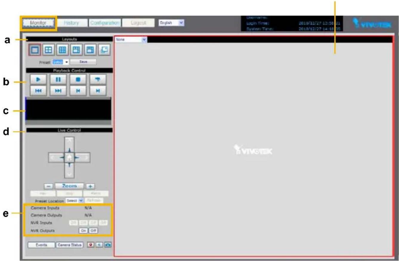
a. Layouts
c. Time Bar and Histogram
e. Digital I/O Control Area
a. Layouts
c. Time Bar and Histogram
e. Digital I/O Control Area
b. Playback Control
d. Live Control Panel
f. Video Cell
NOTE
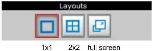
▶ There are only two layouts (1x1,2x2) provided in NR8201.
■ Following pictures show the Monitor page with connected cameras. For more information about how to insert connected cameras, please refer to Device on page 22.
Live viewing mode
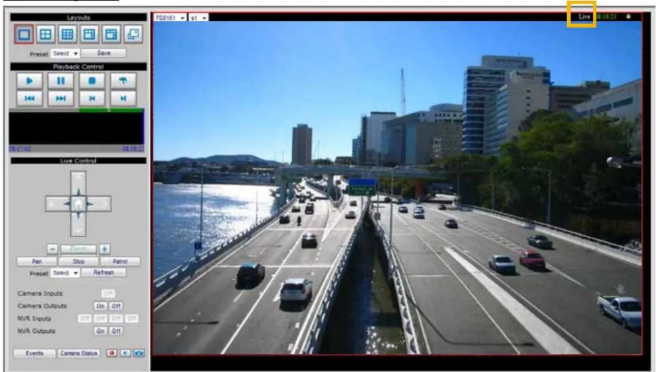
Playback mode
Click on the Histogram to switch to playback mode. The Live Control Panel will turn into Playback Control Panel as below. Click 📋 on the Playback Control Panel, it will switch to live viewing mode.
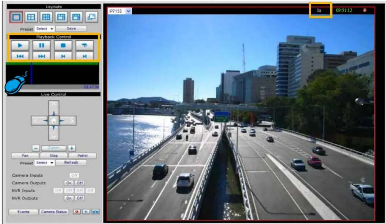
Functions of Monitor Page
Layouts
Click the Layout buttons to change the viewing mode.
■ NR8301
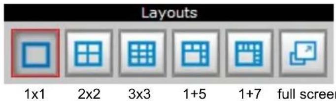
NR8201
Following is an example of 4x4 layout. For each video cell, you can select a linked device on the dropdown list.
Drop-down list of Linked devices
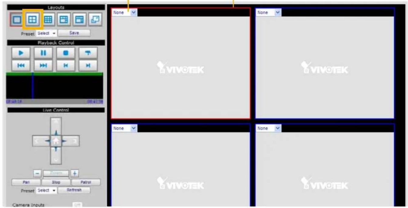
The red frame represents the focused cell.
Time Bar and Histogram
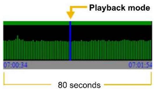
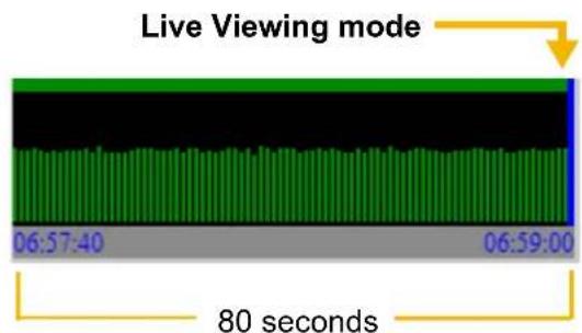
In the Monitoring page, the Histogram only shows video clip for 80 seconds as below. The blue line is the Time Bar. The green line is the status of motion value windows.
Digital I/O Control Area
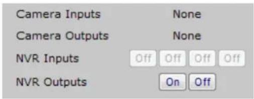
This column shows the DI status, and you can manually turn on/off the DO.
Live Control Panel
Only PTZ and speed dome network cameras will enable the PTZ control panel.
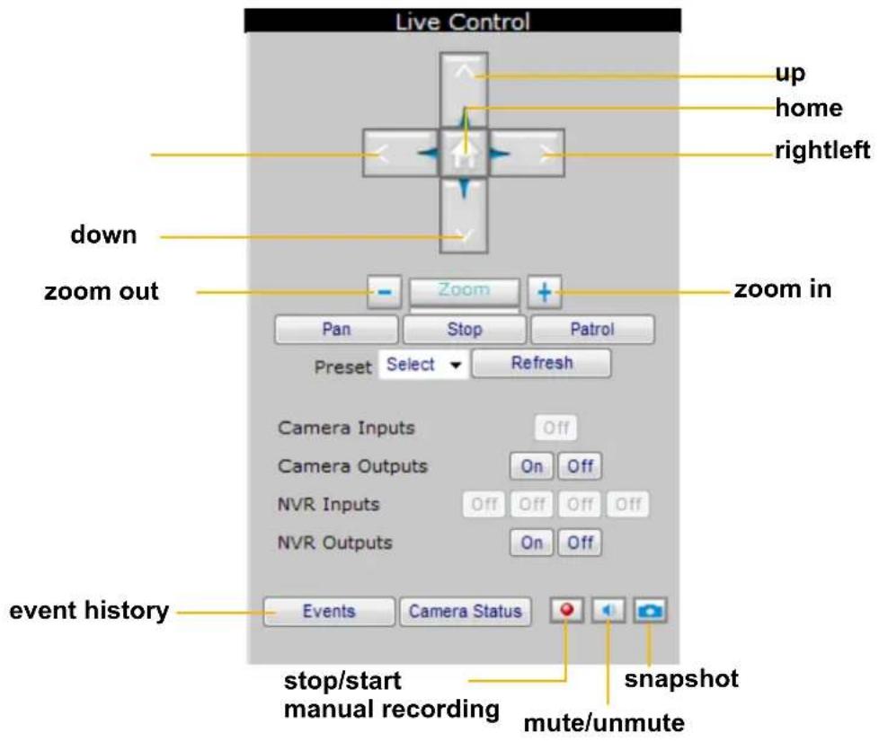
Preset: On the drop-down list, there are preset locations you've set on the Configuration page of the cameras.
Refresh: Click it to update the preset locations.
Manual Recording Button: If you click Manual Recording Button on the Live Control Panel, the Recording Type will turn into Manual recording. If you want to stop manual recording, click the button again.
Snapshot: Click to save a snapshot of the video you select. To configure Snapshot and Download Path, please refer to System on page 44.
Playback Control Panel
There are eight buttons for you to playback the recorded video clips (current 80 seconds).
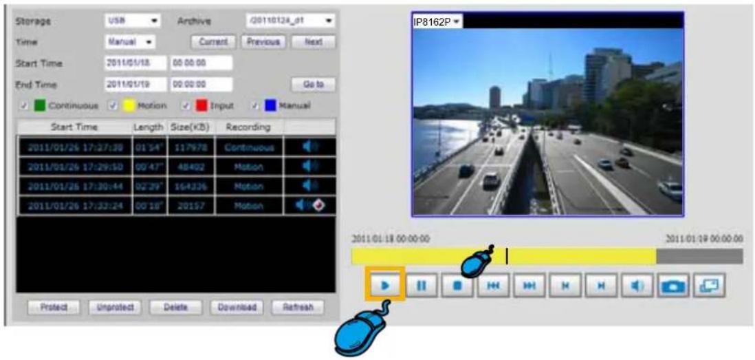
Play: To start or resume playback at normal speed.
Pause: To pause the playback. Click again to step forward a frame.
Stop: To stop video playback.
Live: To switch to live video.
Play rewind: To rewind recorded video. Click again to speed up (-4x, -16x, -64x).
Play forward: To playback recorded video. Click again to speed up (4x, 16x, 64x).
Previous: During playing mode, click this button to play the last video clip back in 60 seconds. During pause mode, click this button to step back to display the last I-frame.
Next: During playing mode, click this button to play the next video clip forward in 60 seconds. During pause mode, click this button to step back to display the next I-frame.
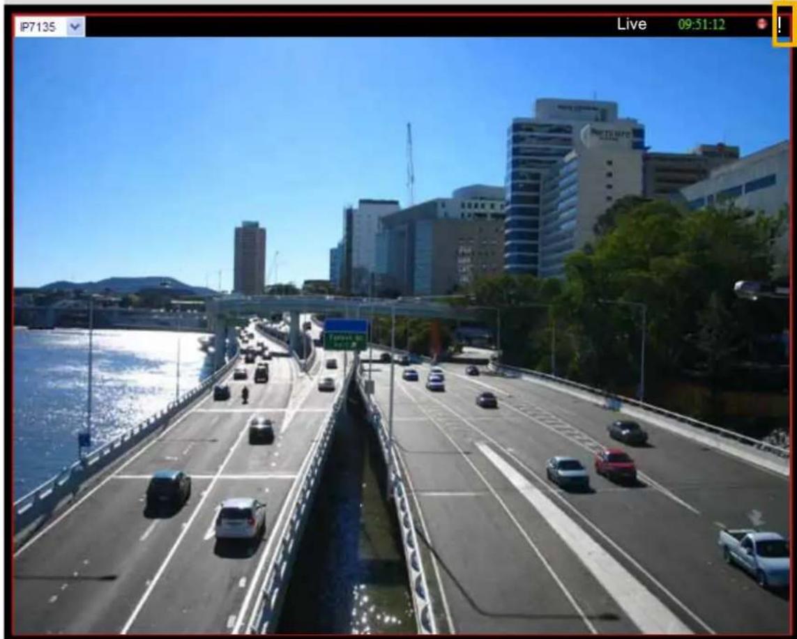
Event Trigger Alarm
an exclamation mark
natural_image
Aerial view of a multi-lane highway with vehicles, surrounded by modern buildings and greenery under a clear blue sky (no visible text or symbols)If you have set up an event for a device, an exclamation mark will flash on the upper right corner of the video cell when an event is triggered.
History
This page offers user a time-navigation interface to playback recorded video and browse the live view from linked devices.
User Interface of History Page
Click History on the Main Menu, the user interface of History page will be displayed as below:
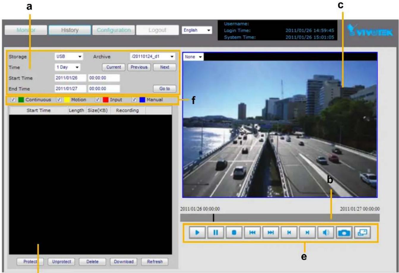
d
a. Time Picker
c. Recorded Video Clips
e. Playback Control Panel
b. Time Bar and Histogram
d. Video Viewing Window
f. Recording Mode
Functions of History Page
Time Picker
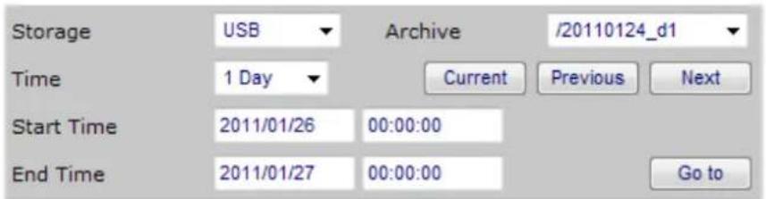
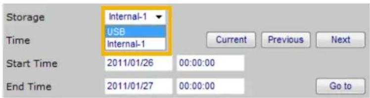
Storage: Select a storage device you want to review.
Select Time: Select a period of time (1 Hour, Day, 1 Week, 1 Month, or Manually), which decides the length of histogram.
Start Time: The beginning of the selected period of time.
End Time: The end of the selected period of time.
Current : Click this button to go to the current period of time (current Hour, Day, Week, or Month).
Previous : Click this button to go the last period of time (last Hour, Day, Week, or Month).
Next : Click this button to go the next period of time (next Hour, Day, Week, or Month).
Go to : Manually input the time, and then click this button to go the selected period of time (selected Hour, Day, Week, or Month).
Time Bar and Histogram / Recorded Video Clips
The recorded video clips in the selected period of time will show up on the histogram and be listed in the recorded video clips window. In the following histogram, all recorded video clips are based on Continuous recording (green bar). The black Time Bar refers to the current time.
Continuous recording
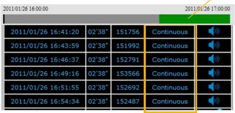

The latest video clip, and still recording.

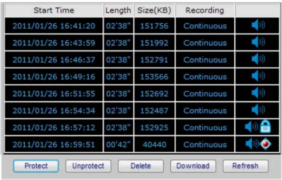
: The video with recorded audio. To enable the audio function, please go to Configuration > Device nable the Audio Compression setting of the Device.
Protect
: If you want to prevent a video clip from being erased by the latest video clip, select the video clip and then click this button. A Protect Icon will show up.
Unprotect
: Select a video clip with Protect Icon and then click this button. Then the video clip becomes unprotected.
Delete
: If you want to delete a video clip, select it and then click this button.
Download
: If you want to export an AVI file of a video clip to your local computer, select it and then click this button.
Refresh
: Click this button to refresh the latest video clip.
Recording Type
The following color bar will show up on the histogram according to the recording type.

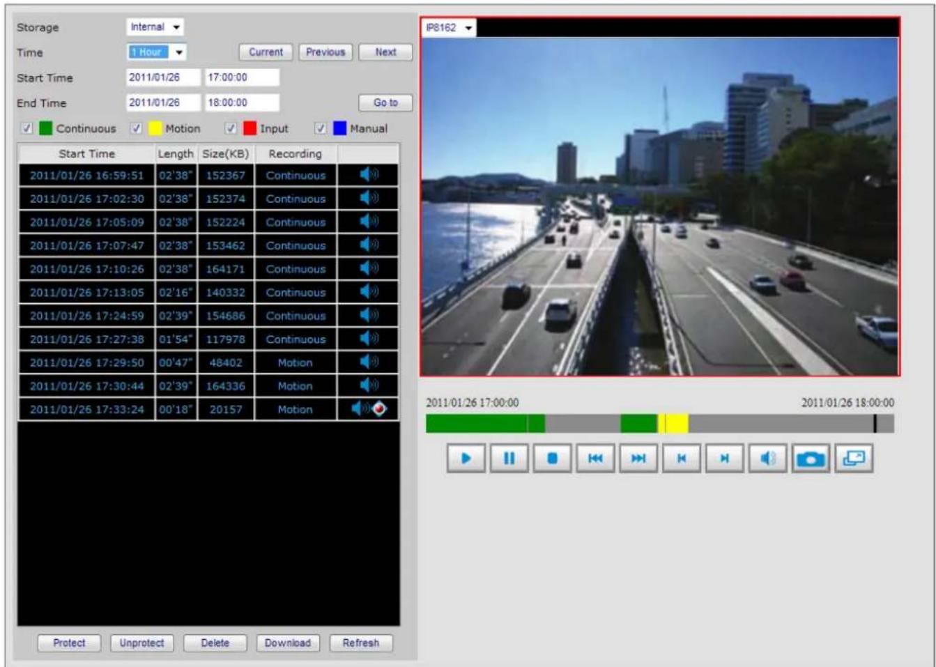
■ Green bar (Continuous): Record video according to continuous mode. For detailed configuration, refer to Recording Policy on page 37.
■ Yellow bar (Motion): Record video when motion triggers on linked device. For detailed configuration, please refer to Recording Policy on page 37.
■ Red bar (Input): Record video when an external digital input triggers on linked cameras or on the Network Video Recorder. For detailed configuration, please refer to Recording Policy on page 37.
■ Blue bar (Manual): Record video when the user starts manual recording. Please refer to Manual Recording on page 55 for detailed information.
Example:
Following video clip list contains different kinds of recording mode.
NOTE
For the length of Continuous Recording, Motion Recording, Input Recording, and Manual Recording, please refer to Recording Policy on page 37 for detailed configuration.
■ There are two ways to playback recorded video clips:
- Click a desired time on the histogram.
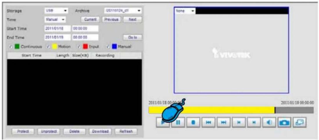
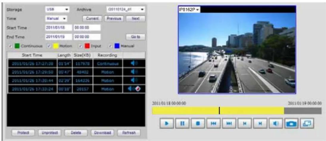
- Click on a video clip, and then click ▶ on the playback control panel.
Video Viewing Window
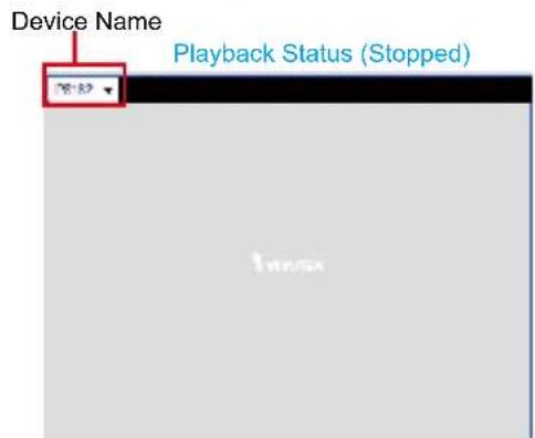
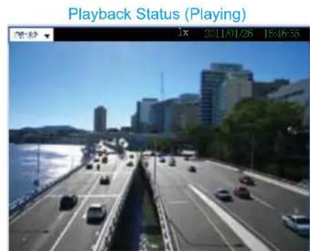
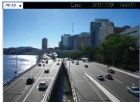
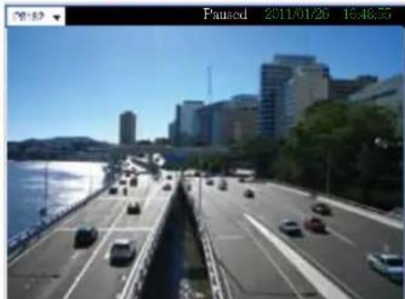
This window playbacks the recorded videos. If you have not selected a video, the playback status will be empty as pic01. Once you select a video clip to play, the video viewing window will begin to playback the selected recorded video clips as pic02. If you click 📋 on the playback control panel, the video viewing window will switch to the live video view as pic03. If you click 📋, the video will paused as pic04.
pic01
pic02
Playback Status (Live)
natural_image
Street view of a coastal city with vehicles and modern buildings under a clear blue sky (no visible text or symbols)pic03
Playback Status (Paused)
natural_image
Street view of a coastal city with vehicles and modern buildings in the background under a clear blue sky (no visible text or symbols)pic04
Playback Control Panel
There are eight buttons for you to playback the recorded video clips.
Play: To start or resume playback at normal speed.
Pause: To pause the playback. Click again to step forward a frame.
Stop: To stop video playback.
Play rewind: To rewind recorded video. Click again to speed up (-4x, -16x, -64x).
Play forward: To playback recorded video. Click again to speed up (4x, 16x, 64x).
Previous: During playing mode, click this button to move to play the last video clip. During pause mode, click this button to step back to display the last I-frame.
Next: During playing mode, click this button to move to play the next video clip. During pause mode, click this button to step back to display the next I-frame.
Mute/Unmute: To mute / unmute the audio of the video files.
Snapshot: To snapshot the image of the moment and save it in the designed path.
Full screen: To enlarge the live view window to full fill the browser window.
Appendix
Technical Specifications
System
· CPU: Marvell 88F6281 1.2G
- Flash: 128MB
- RAM: DDR-SRAM 512MB
- Embedded OS: Linux
Channels
- NR8201: Support up to 4 channels
- NR8301: Support up to 8 channels
Hard Disk
- NR8201: Support 1 x 3.5" SATA I/II HDD, up to 2TB (Support external eSATA interface)
- NR8301: Support 2 x 3.5" SATA I/II HDD, up to 4TB (Support RAID 0, 1 scalable storage)
Compatibility
- Support VIVOTEK all series of network cameras
Codec
- Video compression: H.264/MJPEG/MPEG-4
- Audio compression: AAC/GAMR/G.711
Recording Throughput
- Total 50Mbps
NR8201: 4 x 30fps @ 1080P
NR8301: 8 x 30fps @ 1280x800
Recording Policy
- Alarm recording
- Scheduled recording
- Continuous recording
- Manual recording
Connectors
- 1 x Gigabit, RJ45 (1 WAN port)
- NR8201: 4 x Ethernet 10/100 BaseT, RJ45 (4 LAN ports)
- NR8301: 8 x Ethernet 10/100 BaseT, RJ45 ( 8 LAN ports)
- USB socket for backup
- Terminal block: 4 digital input, 1 relay output, and 1 power output with 12V Max. 1A
Camera Management
- Auto or manual installation for VIVOTEK cameras
- Video and network configuration through NR8301
Pan/Tilt/Zoom Control
- Pan/tilt/zoom control of VIVOTEK cameras
History Playback
- Playback of recorded media with time navigations
Networking
- Protocols: IPv4, TCP/IP, HTTP, RTSP/RTP/RTCP, IGMP, SMTP, FTP, DHCP, NTP,
DNS, DDNS, 3GPP
Alarm and Event Management
- Four D/I and one D/O for external sensor and alarm
Event notification using SMTP
Security
- Multi-level user access with password protection
- IP address filtering
Users
Camera live and playback viewing for up to 10 clients
Dimension
· 446.4 mm (W) x 330.2 mm (D) x 43.6 mm (H)
Weight
· NR8201: 4kg
· NR8301: 4.7kg
LED Indicator
- System power, PoE, status and hard disk indicators
· Network link indicator
Power
· 100 \~ 240V AC
· 802.3af compliant Power-over-Ethernet
• Power consumption:
NR8201: Max. 0.48 W (without PoE camera); Max. 60 W (with 4 PoE cameras)
NR8301: Max. 0.96 W (without PoE camera); Max. 120 W (with 8 PoE cameras)
Approvals
CE, FCC, VCCI, C-Tick, CB
Operating Environments
· Temperature: 0 \~ 50 °C (32 \~ 122 °F)
· Humidity: 20% \~ 80% RH
Viewing System Requirements
- OS: Microsoft Windows 2000/XP/Vista/Win7
- Browser: Internet Explorer 6 or above
· 3GPP access
Installation, Management and Maintenance
· VAST central management software
· Installation Wizard 2
- Support firmware upgrade
· Support VIVOTEK joystick
Warranty
· 24 months
All specifications are subject to change without notice. Copyright ©2011 VIVOTEK INC. All rights reserved.
URL Commands for the Network Camera
RTSP URL command
RTSP://ip_address[:port]/cameraID
where camera ID is mac address with 00,
For instance, if mac is 00:02:dd:dd:dd:dd the camera ID is 0002dddddddd00
url example is RTSP://192.168.100.1/0002dddddddd00
- Network
- Video Recorder
- Table of Contents
- Overview....3
- Installation 8
- Home Page....20
- Configuration 22
- Monitor....52
- History 57
- Appendix....63
- Overview
- Read before use
- Package contents
- Revision History
- Physical description
- General I/O Terminal Block
- DI/DO Diagram
- Status LED
- Hardware System Requirement
- Computer:
- Hard disk:
- Hardware Reset
- Restore:
- Installation
- Hard Disk installation
- NOTE
- Network deployment
- Device Connection
- Install the IW2 Utility
- Supported & Unsupported Connections
- IMPORTANT!
- Getting Started
- Set up NR8201/8301 in LAN
- LAN Settings Configuration
- Network Settings Configuration
- Internet connection with private DHCP (dynamic IP)
- Internet connection with static IP
- Internet connection via PPPoE (Point-to-Point over Ethernet)
- Home Page
- Main menu
- Language
- Status panel
- Configuration
- Device
- Auto search by device installer or manually install in LAN
- Manually install in WAN
- LAN
- LAN / DHCP Server
- WARNING!
- Access list
- Allowed list / Denied list
- Delete allowed list / Delete denied list
- DDNS
- DDNS Settings
- ■ Safe100.net
- Security
- Root Password
- Manage Privilege
- Manage User
- Schedule
- Recording Policy
- For example:
- ■ Configuration > Device
- ■ Configuration > Recording Policy
- ■ Recorded video clips on History page.
- Recording Mode
- Trigger
- Trigger Configuration
- Trigger Event
- From linked devices
- From the network video recorder
- Trigger Action
- Actions of the system
- Actions of the linked devices
- Actions of the network video recorder
- Layout
- System
- System Time
- E-mail Server
- FTP Server
- Digital Input
- Digital Output
- VAST
- Maintenance
- Firmware
- Storage
- ■NR8201
- NR8301
- RAID
- Backup
- Scheduled Backup
- Manually Backup
- USB
- System log
- Joystick
- Monitor
- User Interface of Monitor Page
- Playback mode
- Functions of Monitor Page
- Layouts
- Time Bar and Histogram
- Digital I/O Control Area
- Live Control Panel
- Playback Control Panel
- History
- User Interface of History Page
- Functions of History Page
- Time Bar and Histogram / Recorded Video Clips
- Recording Type
- Example:
- Video Viewing Window
- Appendix
- Technical Specifications
- Channels
- Hard Disk
- Compatibility
- Codec
- Recording Throughput
- Connectors
- Camera Management
- Pan/Tilt/Zoom Control
- History Playback
- Networking
- Alarm and Event Management
- Users
- Dimension
- Weight
- LED Indicator
- Power
- Approvals
- Operating Environments
- Viewing System Requirements
- Installation, Management and Maintenance
- Warranty
- URL Commands for the Network Camera
Brand : Vivotek
Model : NR8301
Category : Voice recorder