
ND8401 - Voice recorder Vivotek - Free user manual and instructions
Find the device manual for free ND8401 Vivotek in PDF.


| Product Type | Voice Recorder |
| Brand | Vivotek |
| Model | ND8401 |
| Dimensions (W x D x H) | 120 mm x 60 mm x 15 mm |
| Weight | 100 g |
| Power Source | Built-in rechargeable battery (USB charging) |
| Recording Format | MP3 / WAV |
| Storage Capacity | 8 GB internal memory (expandable via microSD) |
| Recording Modes | High Quality, Standard, Long Play |
| Playback Features | Variable speed, A-B repeat, file sorting |
| Connectivity | USB 2.0, 3.5 mm headphone jack, built-in microphone |
| Battery Life | Up to 20 hours continuous recording |
| Display | 1.5-inch LCD with backlight |
| Maintenance & Cleaning | Clean with a soft dry cloth; avoid liquids |
| Safety Precautions | Keep away from moisture and extreme temperatures |
| Spare Parts & Repairability | Not user-serviceable; contact support for repair |
Frequently Asked Questions - ND8401 Vivotek
User questions about ND8401 Vivotek
0 question about this device. Answer the ones you know or ask your own.
Ask a new question about this device
Download the instructions for your Voice recorder in PDF format for free! Find your manual ND8401 - Vivotek and take your electronic device back in hand. On this page are published all the documents necessary for the use of your device. ND8401 by Vivotek.
USER MANUAL ND8401 Vivotek
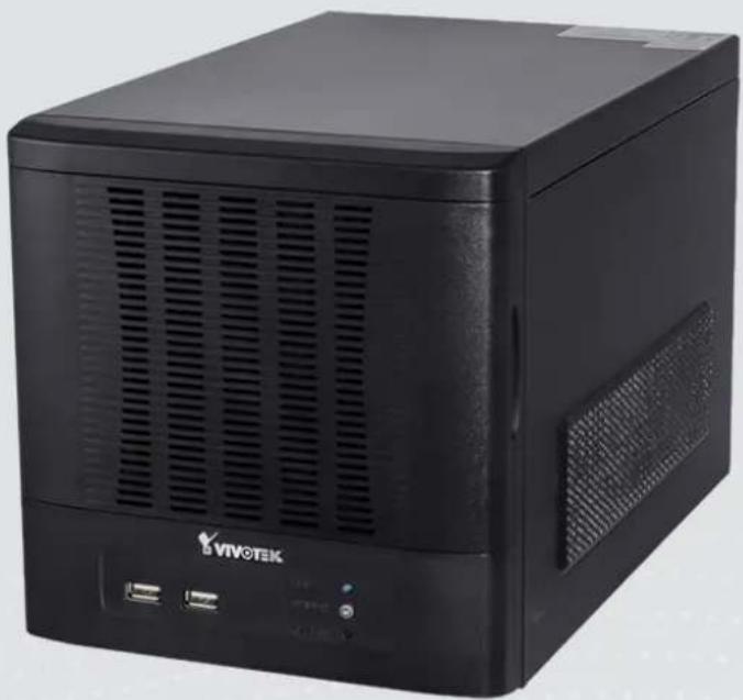
ND8401 Network Video Recorder
User's Manual
VAST inside • HD Local Display •
Full Integration with VIVOTEK Cameras
natural_image
Black Vivotek desktop computer with ventilation slots and ports (no visible text or symbols on body)Rev. 1.1b
Table of Contents
Revision History 8
Chapter One Hardware Installation and Initial Configuration 10
Introducing ND8401 Network Video Recorder 10
Special Features 10
Physical Description 11
Hardware Installation....12
Network Deployment....15
Initial Configuration....16
Ready to Use....19
NVR Desktop Elements....22
Control Center 22
Menu Bar....23
Alarm Sound 23
Chapter Two NVR LiveClient Configuration 24
VAST LiveClient Functionality 25
VAST Server 26
Activating the VAST Server 26
How to Stop/Reboot the Server....26
LiveClient Configuration 27
Opening the LiveClient Interface and Logging in 27
LiveClient User Interface 28
Menu Bar....28
Status Panel....28
Quick Access Bar 29
Live Video Monitoring Window....29
Hierarchical Management Tree 30
Camera Control Panel....31
Pan/Tilt/Zoom (PTZ) Control Panel 31
Two Way Audio Control Panel....32
Event Window 33
Instant Playback....34
Instant Replay 34
Audio Control 36
How to Manage Devices (Cameras) 37
Insert Cameras....37
Enable SVC 41
Update Devices....44
Delete Devices from the Station....45
Batch Insert Cameras 46
Camera Configuration 50
View Live Videos....53
Dual / Multiple Streams 53
Fisheye Display Modes....53
Refresh....58
Streaming Server 58
Get Public IP 58
Camera Settings 59
Remove Live Video from the Video Monitoring Window 59
How to Change the VAST LiveClient Layout....60
Changing the Layout of the Live Video Monitoring Window....60
Switch Video Channels 60
Configure Layout Mode....60
Rotating Video Pages 61
Edit Layout....61
Maximize the Live Video Monitoring Window....63
How to Manage Stations 65
Relay Settings....65
How to Manage User Accounts....66
The Default User Roles and Permissions of User Accounts 66
Manage a User Account....68
Add a New User Account 68
Permission of the User Account 69
Delete the User Account 70
How to Set up Association Management....71
Association Management....71
How to Set up Event Management....73
Event Management....74
How to Configure the Station General Settings....81
Server Settings....81
Log Settings 81
Reboot Settings....82
How to Configure Station Network Settings 83
Port Settings....83
UPnP Settings 83
Proxy Settings 83
Web Access Settings....83
How to Edit Recording Stoage 84
Recording Storage Settings 84
Default Storage Group Settings 85
Add New Storage Group(s)....88
How to Edit Recording Schedules....89
Edit Schedule List 90
Add Schedules....90
Rename Schedules....90
Delete Schedules....90
Load/Save Schedule Templates....91
Edit Camera List....92
Edit Time Frame List 93
Add New Time Frames....94
Recording Settings....95
The Concept of Repeat Frequency 96
Repeat Frequency: Daily Setting 97
Repeat Frequency: Weekly Setting (Day-based)....100
Repeat Frequency: Monthly Setting (Day-based).... 103
Repeat Frequency: Yearly Setting (Day-based).... 105
How to Manually Begin /Stop Recording....107
How to Edit Scheduled Backup Settings....108
Select Backup Source 108
Setup Backup Schedule....109
Select Backup Target 109
Other Options....109
How to Configure Station Server Settings....110
DDNS Settings....110
Network Storage Server Settings....111
SMTP Settings 112
How to Use the Talk Panel 113
Add a Camera to the Talk Panel....113
Remove a Camera from the Talk Panel 115
How to Configure E-map Settings....116
Upload an E-map 116
E-map Settings Page (View Mode)....117
Quick Access Bar....118
Status Panel....118
E-map Settings Page (Edit Mode)....119
Device Management 120
Live View Dialog Settings....121
Open Live View Dialog....121
Send to Single View 121
E-map Link 122
How to Configure Client Settings 125
Snapshot Settings 125
Taking a Snapshot....126
Recording Settings....127
Type 1: Record to EXE 127
Type 2: Record to 3GP....127
Type 3: Record to AVI 128
Built-in Media Player--EXE....131
View Settings.... 133
Display Location....133
Date and Time Format 134
Video Display Mode 134
Font Settings....134
General Settings 135
System Settings 135
Event Settings....136
Rotation Settings.... 136
Display Settings 137
Joystick Settings 139
Enable Joystick 139
Proxy Settings 143
How to Use PiP (Picture-in-Picture) 144
Enable PiP....144
Global View 144
ROI (Region of Interest) 145
Digital Zoom In....145
Snapshot Zoomed In Image.... 145
PiP Settings....145
How to Configure Video Enhancement 146
Basic Image Adjustment.... 146
Defog....148
Apply a Preset Defog Profile.... 148
Create a New Defog Profile 149
How to Search for a Device on the Hierarchical Device Tree 151
How to Lock LiveClient for Security Concerns 152
How to Log out from the VAST Server 152
How to Exit VAST LiveClient 152
Launch Playback & Return to System Manager.... 153
Second View 153
Chapter Three NVR Playback Configuration.... 154
Activating VAST Playback and Logging in to a Server 154
VAST Playback User Interface 156
Menu Bar....156
Status Panel....156
Quick Access Bar 157
Recorded Video Playback Window 157
Query Panel-- Browsing Page.... 158
Query Panel--Time Search Page 159
Query Panel--Event Search Page....160
Query Panel--Bookmark Search Page....161
Query Panel--Log Viewer Page.... 162
Video Clips List Window....163
Playback Control Panel....164
How to Playback Recorded Video....165
Select a Recorded Video Clip 165
Remove Recorded Video Clips from Video Cells.... 167
Timeline Slider Bar and Histogram.... 167
Zoom in / out of the Histogram....168
Synchronous Playback....169
Audio Control 171
How to Change the Playback Layout....172
Changing the Layout of the Recorded Video Playback Window.... 172
Switch Video Channels 172
Configure Layout Mode....172
Maximize the Recorded Video Playback Window.... 173
How to Backup Recorded Video 175
How to Search for a Video Clip Taken at a Specific Time 181
How to Add a Bookmark....182
How to Search for Events.... 183
Select Event Category 184
Event Category- All Events 184
Event Category- All Motion Events.... 184
Event Category- All IVA events 185
Event Category- All DI Events.... 185
Event Category- Named DI Events 186
Start Event Search 187
Backup the Event Videos 188
How to Search for a Bookmark 189
How to Search Logs 190
Select Log Category/Log Type/Log Level 191
Search All Local Logs....192
Search Login History....192
Search Login Activities....193
How to Configure Client Settings 195
Snapshot Settings 195
Export Settings....195
View Settings....197
Proxy Settings....197
General Settings 197
System Settings 197
Display Settings 197
How to Configure Video Enhancement 197
How to Search for a Device on the Hierarchical Management Tree 197
How to Lock VAST Playback for Security Concerns 198
How to Log out from the VAST Server 198
How to Exit VAST Playback....198
Chapter Four Auxiliary Utilities 199
Service 200
Import and Export Utility 200
Installation Wizard 2 202
Shepherd....203
Upgrade 205
File Manager 206
Keyboard 206
Disk Status 207
Network Status 208
System Status 209
Appendix Rebuilding a RAID Volume 210
Revision History
Rev. 1.0: Initial release.
Rev. 1.1a: Corrected description of the functions on e-map's right-click menu.
Rev. 1.1b:
- Added short description for the Auto stream size feature.
- Added the Bookmark function.
- Added description for the Instant Replay function (on a remote client).
Read Before Use
The use of surveillance devices may be prohibited by law in your country. The Network Camera is not only a high-performance web-ready camera but can also be part of a flexible surveillance system. It is the user's responsibility to ensure that the operation of such devices is legal before installing this unit for its intended use.
It is important to first verify that all contents received are complete according to the Package Contents listed below. Take note of the warnings in the Quick Installation Guide before the Network Camera is installed; then carefully read and follow the instructions in the Installation chapter to avoid damage due to faulty assembly and installation. This also ensures the product is used properly as intended.
The Network Camera is a network device and its use should be straightforward for those who have basic networking knowledge. It is designed for various applications including video sharing, general security/surveillance, etc. The Configuration chapter suggests ways to best utilize the Network Camera and ensure proper operations. For creative and professional developers, the URL Commands of the Network Camera section serves as a helpful reference to customizing existing homepages or integrating with the current web server.
Package Contents
■ ND8401
■ Power cord
■ Software CD
■ Warranty Card
■ Quick Installation Guide
■ Screws and bezel keys

NOTE:
The operating system and VAST server are installed on an IDE flash mounted on the main board. There is no need to install software.
Symbols and Statements in this Document

INFORMATION: provides important messages or advices that might help prevent inconvenient or problem situations.

NOTE: Notices provide guidance or advices that are related to the functional integrity of the machine.

Tips: Tips are useful information that helps enhance or facilitae an installation, function, or process.

WARNING! or IMPORTANT: These statements indicate situations that can be dangerous or hazardous to the machine or you.

Electrical Hazard: This statement appears when high voltage electrical hazards might occur to an operator.
Chapter One Hardware Installation and Initial Configuration
Introducing ND8401 Network Video Recorder
VIVOTEK ND8401 is a 16-CH Network Video Recorder designed for sophisticated recording applications. The unit is equipped with an Intel Dual-core Atom Processor with maximum recording throughput at a robust 96 Mbps. RAID 0/1/5/10 is supported with four HDDs, with an external eSATA port for additional expansion. Like VIVOTEK NVR ND8301, a local display output port is available with full HD resolution (1920x1080), eliminating the need for a separate PC to view video from the unit. Setup of parameters such as IP address, HDD to logical volumes, and basic camera configuration can easily be performed with the setup wizard, making the ND8401 the easiest NVR to use yet. When connecting ND8401 to more than one of the same model of VIVOTEK camera, the “Shepherd” program can be used to duplicate the configuration to multiple cameras.
VIVOTEK's professional software VAST is installed in ND8401 with performance tuning, allowing for simple and effective management of a surveillance system using the LiveClient and Playback programs. As VIVOTEK's camera features are fully integrated into VAST, cutting-edge technologies such as Activity Adaptive Recording can be utilized to conserve bandwidth and optimize recording. A CMS server running VAST software can also directly control the ND8401, and compatibility with the iViewer application allows for remote access to the ND8401 on handheld devices. By integrating all of the components together using VIVOTEK's ND8401, network cameras, VAST and iViewer software, users can realize a fully-featured and robust next-generation surveillance system.
Special Features
■ Intelligent PiP Function -- Digital Zoom In Mode
■ Convenient Remote Access via Client/Server Architecture
■ Effective & Reliable Event Trigger Management
■ Real-time 16-channel Live Viewing and single channel (VGA) Playback
■ Multiple Simultaneous Streams for Different Media Platforms
■ Activity Adaptive Streaming for Dramatically Reducing Bandwidth and Storage Space
■ Extremely Versatile Settings for Recording Storage and Recording Schedule Management
■ Role-based User Management to Enhance Security Operations
■ Efficient Data Backup, Search, and Export
■ Intelligent PTZ/ E-PTZ Remote Camera Control
■ Overall Device Management through Intuitive E-map Feature
■ Supports Two Way Audio
■ Supports Auto Stream Size
■ Supports SVC adaptive frame rate setting
* The number of linked devices will depend on the license purchased along with the system.
* The ability to extend devices is also subject to the network bandwidth and computer performance.
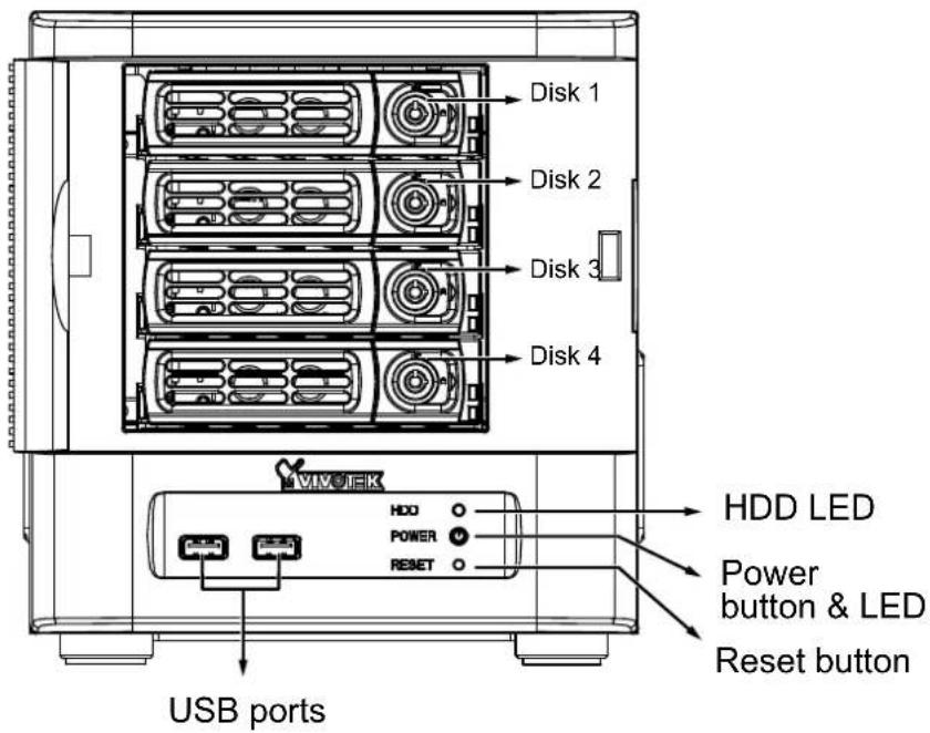
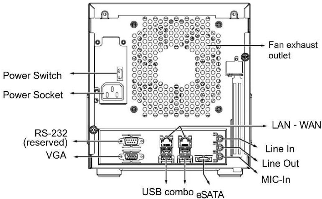
Physical Description

Front View

Rear View

IMPORTANT:
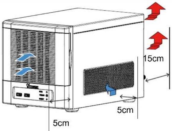
It is important to leave a clearance of 15cm to the rear side of the chassis. The clearance is required to ensure an adequate airflow through the chassis to ventilate heat. A 5cm clearance is also required on both sides of the chassis.
To ensure normal operation, maintain ambient airflow. Do not block the airflow around chassis such as placing the system in a closed cabinet.
For a RAID volume configuration, it is recommended you use hard drives of the same model featuring the same capacity and rotation speed, even running the same version of firmware.
Hardware Installation
SATA hard disk(s) are user-supplied. The network video recorder can readily accommodate most of the off-the-shelf SATA hard drives.
- Open the front panel.
- Use the included bezel key to unlock the bezel lock.
- Open the drive tray bezel by flipping the bezel latch to the side. The bezel lever will spring open, and you can then remove the drive tray.

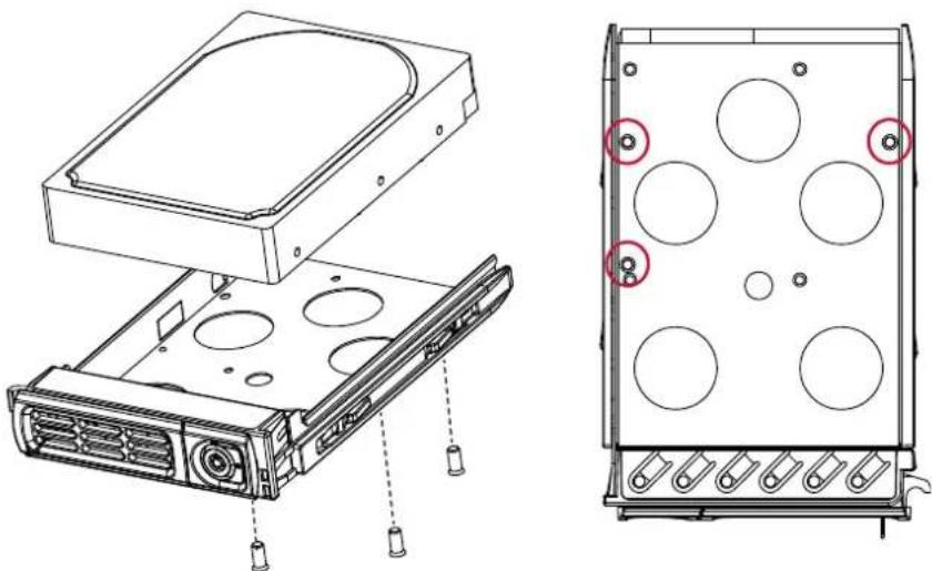
- Install your hard disk to the drive tray. Gently put the hard disk into drive tray with its label side facing up and the connector side facing the inside of the chassis. Flip the hard drive and drive tray over, and then secure the hard drive by fastening 3 screws.
natural_image
Technical line drawing of an internal hard drive with mounting holes and a rear panel showing circular components (no text or symbols)
IMPORTANT:
Avoid touching the hard drive's circuit board or connector pins. Doing so can damage the hard drive by electro-static discharge.
- Install drive tray by pushing it into drive bay. when it is almost fully inserted, close the bezel. The bezel will secure the back-end connection to the backplane.
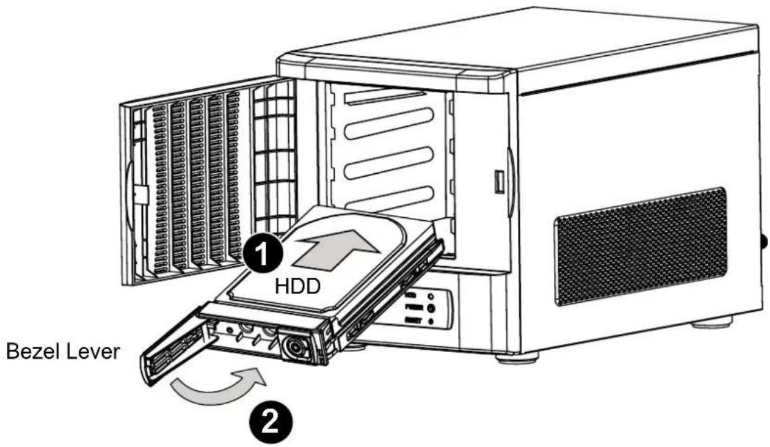
- Use the bezel key to lock the drive tray. Repeat the process to install more disk drives.

Interface Connections
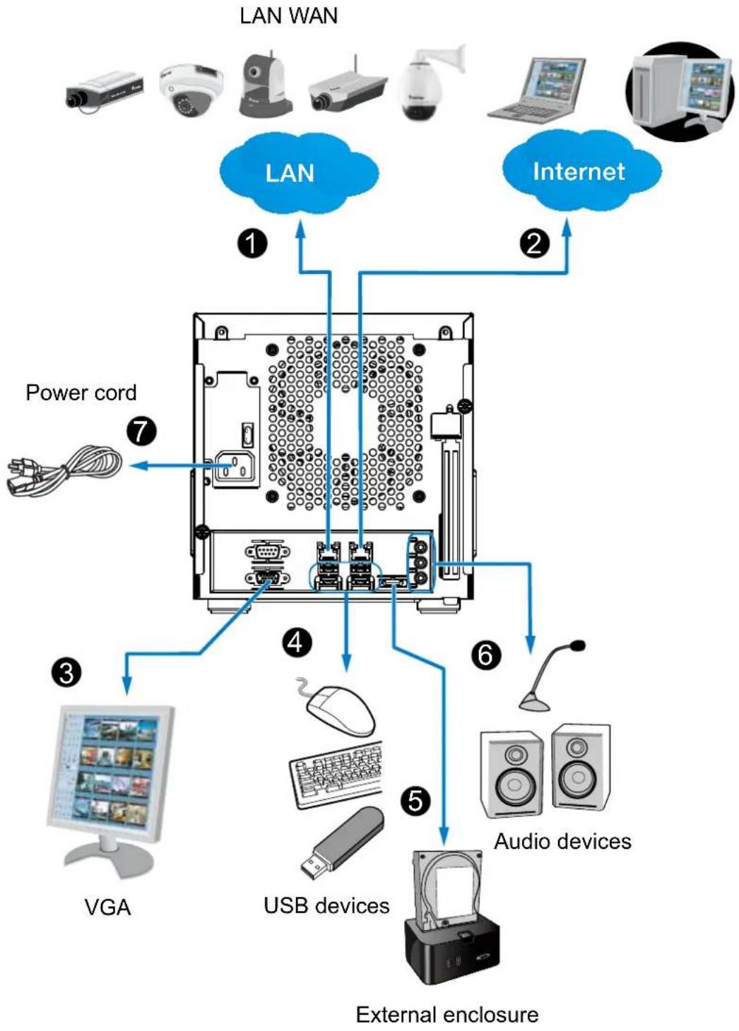
1 & 2. Connect CAT5 or better-quality Ethernet cables to cameras via a local, switched network, or clients through the Internet. Refer to next page for more information.
3. Connect the DB15 VGA port to a monitor (with resolutions up to 1920x1080).
4. Connect USB devices such as keyboard and mouse.
5. If an external eSATA storage enclosure is available, connect it to the eSATA port.
6. Connect speakers or microphone to the phone-jack connectors.
7. Connect the power cord to the power socket 100-240V AC. (50\~60Hz, 3\~1.5A)
flowchart
graph TD
    A["LAN WAN"] --> B["LAN"]
    A --> C["Internet"]
    B --> D["External enclosure"]
    C --> D
    D --> E["USB devices"]
    D --> F["Audio devices"]
    E --> G["VGA"]
    F --> H["Power cord"]
    style A fill:#f9f,stroke:#333
    style B fill:#ccf,stroke:#333
    style C fill:#ccf,stroke:#333
    style D fill:#dfd,stroke:#333
    style E fill:#dfd,stroke:#333
    style F fill:#dfd,stroke:#333
    style G fill:#dfd,stroke:#333
    style H fill:#dfd,stroke:#333
Network Deployment
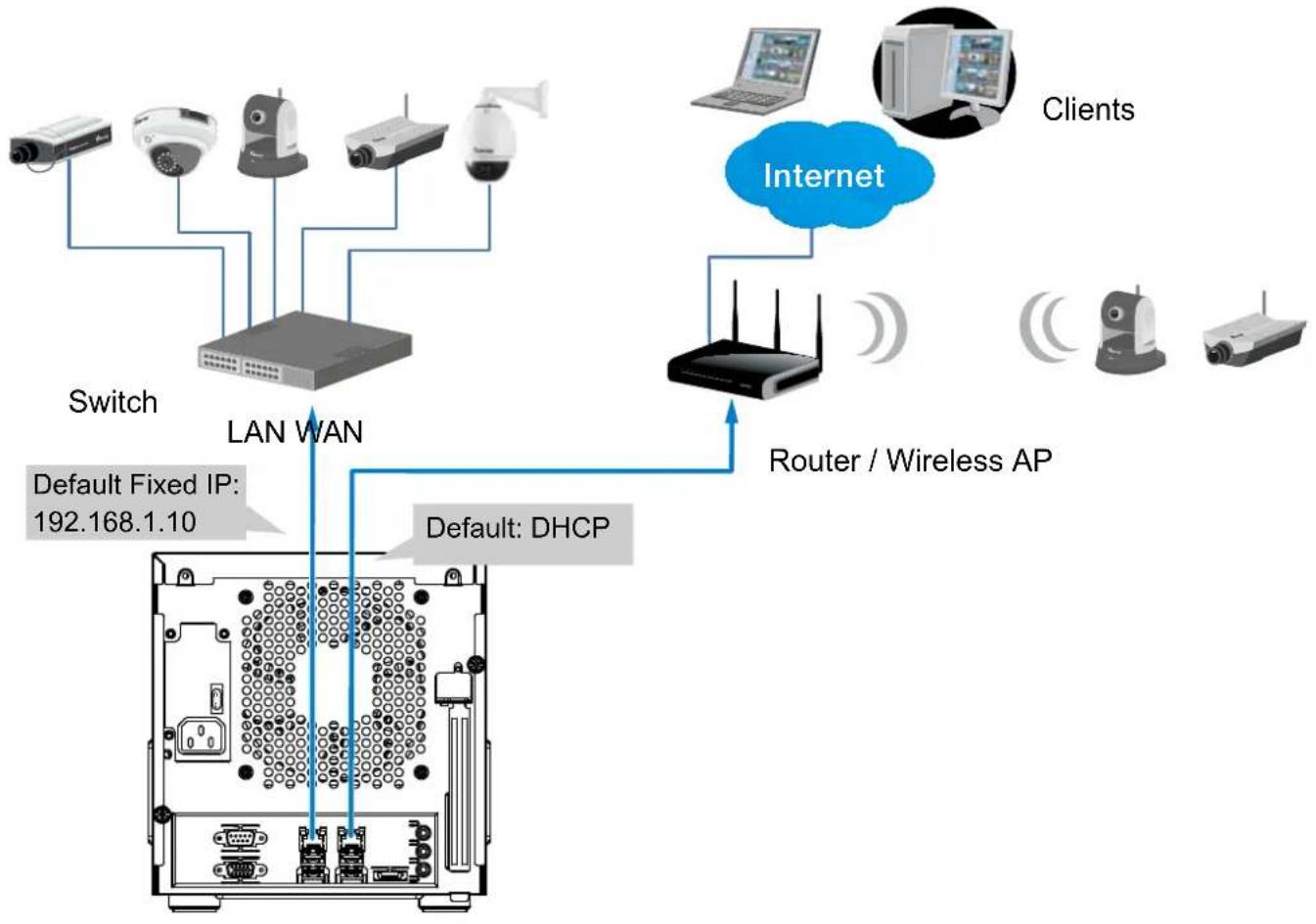
- Connect network cameras to the NVR's LAN ports.
- If you want to access NVR over the Internet, connect the NVR to the Internet via the WAN port. A web console can be established from a remote PC by keying http://
:3454 in a browser's URL address field. However, port forwarding on the router for the TCP port will be necessary. - Flip the power switch (at the rear of chassis) to the ON position, and push the power button to run the NVR.
flowchart
graph TD
    A["Switch"] --> B["LAN WAN"]
    B --> C["Router / Wireless AP"]
    C --> D["Internet"]
    D --> E["Clients"]
    B --> F["Default Fixed IP: 192.168.1.10"]
    B --> G["Default: DHCP"]

NOTE:
The LAN and WAN ports can be configured into the same or different subnets.
If you have cameras connected via the WAN port, make sure the WAN port acquires an IP address from a DHCP server on router or AP. If not, the cameras detected through the WAN port will use the default IPs, e.g., 169.254.xx.xx, and the LiveClient software will not be able to detect their presence.
Initial Configuration
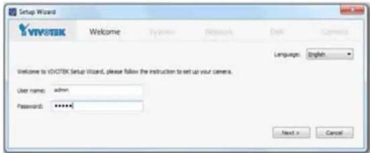
- The system power on self test and OS initialization takes about 2 minutes to complete. Once your NVR is started, you will be prompted by the Setup Wizard. You should then begin the initial setup. The system is booted from an embedded IDE flash. No software installation is required.

IMPORTANT:
-
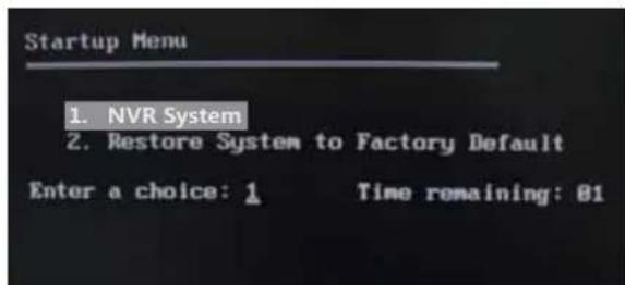
During boot-up, a Startup Menu will prompt allowing you to restore system to factory defaults. This function is only required in circumstances that you need to renew all system settings, such as moving the NVR to a different installation site or network environment.
-
You must install at least one hard drive for the initial configuration. Otherwise, the LiveClient console will not start.
-
Enter the default User name and Password as admin & admin. It is recommended you change the password later to prevent unauthorized access.
-
Click Next to proceed with configuration and follow the onscreen instructions to finish the configuration process.
-
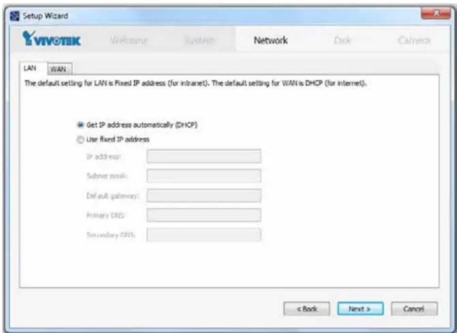
Note the following when you move to the Network page:
4-1. If your local network has a DHCP server, you can select the "Get IP address automatically (DHCP)."
4-2. If your LAN port connects to an isolated switch with cameras attached to it, you can manually assign IP addresses to cameras, and the address for the LAN port itself.
The default static IP for the LAN port is 192.168.1.10.
4-3. Connect your WAN port to a router or AP with the routing capability and then to a DSL or Cable modem.
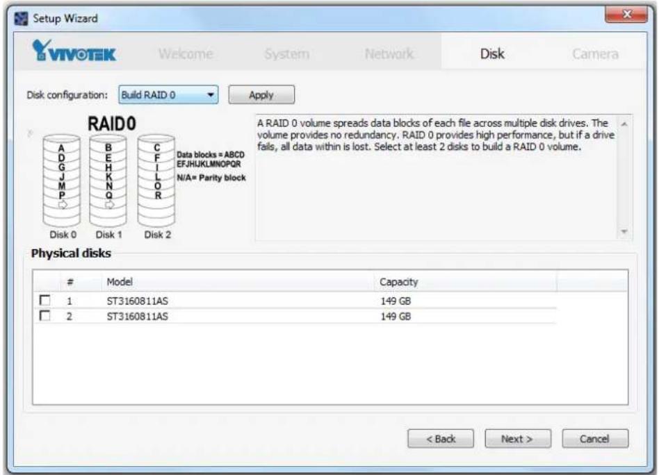
- On the Disk page, Select disk drives by clicking the checkboxes in front of disk drives. Select Build single disk, Build RAID0, RAID1, RAID5, RAID10 or other option from the Disk configuration pull-down menu. Click Apply and wait for a few minutes for the configuration to take effect.
Refer to the description available with every disk volume type on the screen, such as those for RAID0, RAID1, RAID5, or RAID10.
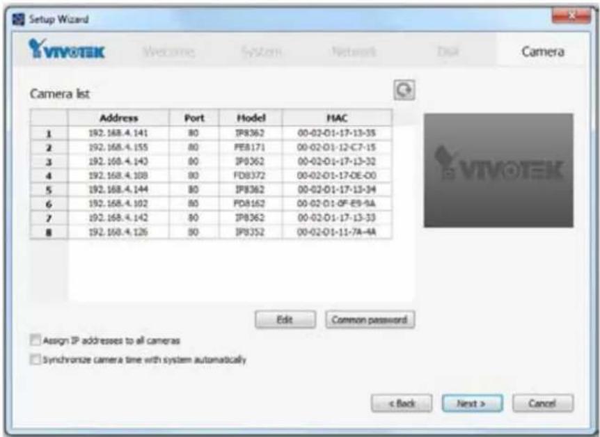
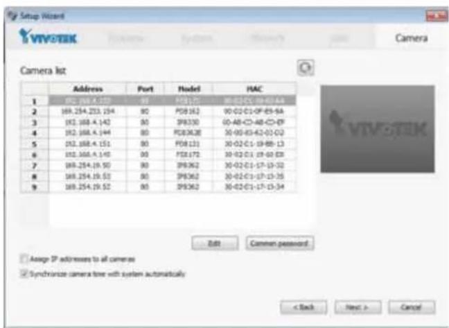
- On the Camera page, all cameras connected through the local network should appear on a Camera list after a brief search. You can manually assign IP addresses by clicking on the cameras' address field. You can also select the "Assign IP addresses to all cameras" checkbox and let NVR assign IPs to cameras.
Click Next to end the initial setup. Make sure you have the cameras' access credentials in order to make individual changes. It is also highly recommended to synchronize cameras' time with that of the NVR system. Click the checkbox below for an automated synchronization.
Ready to Use
- You will then be at the Control Center screen. Double-click on the LiveClient or Playback buttons to configure live viewing and recording settings.
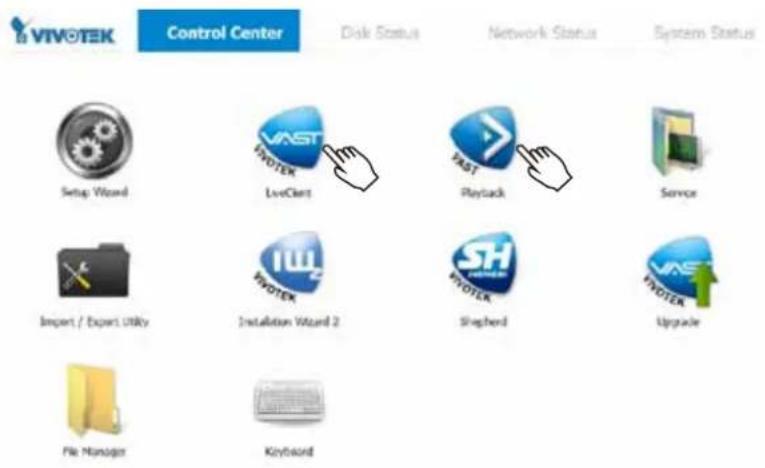

- Open the LiveClient utility to change live view layout, camera streaming frame rate, and other options.
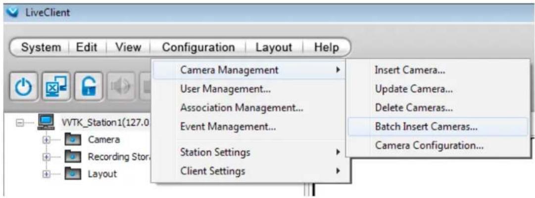
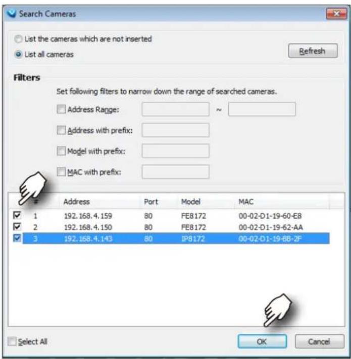
- 3-1. By default, the Batch Insert Cameras window will prompt for you to recruit cameras into your configuration.
You may also access the same configuration page in the Configuration menu. Select Camera Management > Batch Insert Cameras.
3-2. Click on the Search button.
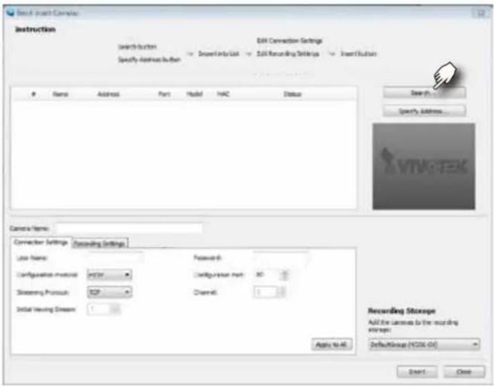
3-3. Select cameras by clicking their checkboxes.
3-4. Click OK, return to the previous window, and click the Insert button.

- It is important to ensure that the live viewing and recording configuration does not exceed the system's limits:
In terms of local display, the default stream 1 for live view can be configured with a resolution up to Full HD 30fps. Stream 1 is also a source for continuous recording. Make sure your cameras' stream 1 resolution does not exceed 1080P at 30fps.
| Compression MJPEG H.264 | ||||||||
| Resolution 1080P | 720P VGA CIF 1080P 720P | VGA CIF | ||||||
| Frame rate 15fps | 30fps | |||||||
| by bit rate / video quality | Good | 6Mbps | 6Mbps | 1Mbps | 512kbps | |||
| No. of streams | - | - | 9 | 16 | 1 | 1 | 3 | 7 |
| Compression | MPEG-4 | |||
| Resolution 1080P | 720P VGA CIF | |||
| Frame rate 30fps | ||||
| by bit rate / video quality | 6Mbps | 6Mbps | 1Mbps | 512kbps |
| No. of streams | 2 | 2 | 5 | 16 |
The NVR supports Auto Stream Size, which automatically adjusts streaming display for efficient leverage of system resources. If you disable the Auto Stream Size function and manually configure your stream settings, you must comply with the limitations listed above.

IMPORTANT:
You may need to configure a recording stream of a particular resolution and bit rate. When doing this, you should make sure the Recording load does not exceed the maximum 96Mbps as the sum of bit rates per second allocated for all recording streams. If you have multiple cameras and the upper bound is exceeded, proceed with the following:
If you configure a RAID5 volume as the recording storage, the maximum system throughput will be reduced to half of the 96Mbps limitation.
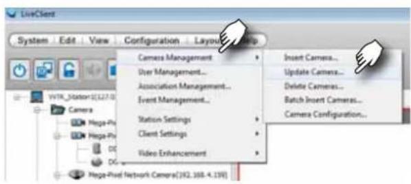
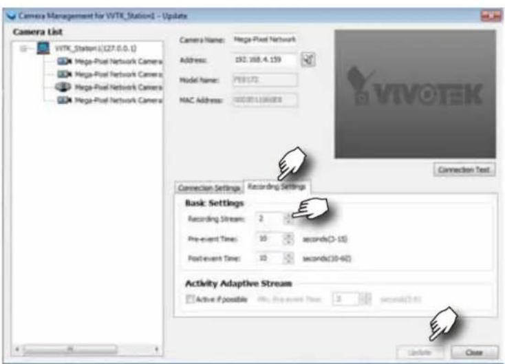
Configure the Recording setting in Configuration > Camera Management > Update Camera. When the Update window prompts, select a camera. Click on the Recording Settings tabbed menu, and select a smaller stream (in higher or lower bit rate or resolution) as the source of recording. Click Update to save your configuration and repeat the setting until the recording load is back within the 96Mbps limitation.
NVR Desktop Elements
Control Center

TVOTEK
Control Center
Disk Status
Network Status
System Status

Menu Bar

Setup Wizard

LiveClient

Playback

Service


Import / Export Utility

Instalation Wizard 2

Shepherd

Upgrade

File Manager

Keyboard

Normally the desktop defaults to the Control Center view, which provides direct access to various functional utilities such as LiveClient and Playback. The functions of these utilities are summarized as follows:
| Utility Description | ||
 | Setup Wizard The Setup Wizard guides your through important steps on initial setup. Most of the storage-related settings are managed through this wizard, such as creating disk volumes, formatting, and breaking down existing disk volumes. | |
 | LiveClient LiveClient and Playback are the most important interfaces to the NVR's various functionalities. LiveClient provides a centralized management interface to the NVR system, provides live viewing, PTZ / E-PTZ operation, PiP, E-Map, etc. Refer to Chapter Two on page 24 for the operation details. | |
 | Playback Playback enables access to recorded videos, snapshot, bookmark, backup, and retrieval of recorded video, and more. Refer to Chapter Three on page 154 for the operation details. | |
 | Service Services enables you to restart or stop the embedded NVR server (VAST server). | |
 | Import/ Export The Import/ Export utility helps preserve current system configuration or reload a previously-saved configuration. | |
 | Installation Wizard 2 | The IW2 utility offers a glimpse of VIVOTEK cameras and the access to them in a local area network. |
 | Shepherd You can use Shepherd to quickly duplicate individual camera configuration (system, video streams, network, security, etc.) to multiple cameras. Please refer to page 192 for more about this utility. | |
Except for LiveClient and Playback, detailed description of the auxiliary functions can be found in Chapter Four on page 188.
 | Upgrade The Upgrade provides access to NVR system updates. | |
 | File Manager The File Manager helps locate particular system or video data when the need arises, say, for retrieving forensic evidences. | |
 | Keyboard If a keyboard is not available, use this virtual keyboard for entering data. | |
 | Power down button | Use it to power down or restart the system. |

NOTE:
The system should always be powered off using the Power Down button on the desktop. If the system should hang for some reasons, you can press the power button on the front panel for 4 seconds to power off the system.
Menu Bar
The menu bar contains the following menus:
| Menu Description | |
| Control Center A | As previously described, the Control Center is the main access point to major functionalities. |
| Disk Status Disk | Status provides a glimpse of Logical Volumes, Physical disk statuses, HDD status reported through S.M.A.R.T. (Self-Monitoring, Analysis and Reporting Technology), and a test tool to check the integrity of individual disk drives. |
| Network Status | Displays the network statuses of the NVR's two GbE Ethernet ports, including network type, IP address, subnet, and gateway information. |
| System Status R | Reports system overall working status. |
Most of the NVR's major functionalities are managed through the LiveClient and Playback interfaces, refer to Chapter 4 for description of auxiliary functions.
The operating system and VAST server are installed on an IDE flash mounted on the main board. There is no need to install software.
Except for LiveClient and Playback, detailed description of the auxiliary functions can be found in Chapter Four started from page 188.
Alarm Sound
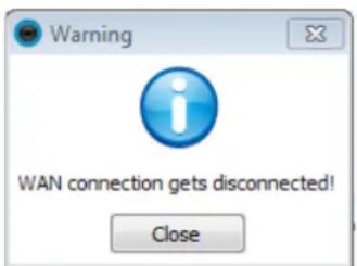
The onboard buzzer will sound if the following occurs: A hard drive is removed or if the LAN or WAN port is disconnected. Mute the alarm by closing the event prompt.
The hard disk reported as "failed" via S.M.A.R.T. will also trigger the alarm sound and a warning message.
Chapter Two NVR LiveClient Configuration
■ Centralized management site for all the logged in clients
■ An NVR can also be managed using a separately-installed LiveClient on a remote PC (rev. 1.7.x or later).
■ Local 1080P HD display
■ Up to 16 video recording channels
■ Store recorded data onto a total of four hard disks (single disks, RAID0, RAID1, RAID5, or RAID10 configurations)
■ Live video for the local/remote LiveClient users
■ Retrieval of recorded video for the local/remote Playback users
LiveClient is the management interface to your NVR server. The server-related settings are made via the VAST LiveClient utility. The convenient and intuitive user interface on the LiveClient helps managing cameras, live monitoring, and recording configurations.
i Information:
- Only users with the Administrator's privileges can manage the LiveClient/s various function groups.
- The maximum length of recording will depend on the video recording settings, the number of cameras, and Storage Group settings.
Below are the approximate numbers for a recording task. A Constant Bit Rate method (fixed bit rate per second) is recommended to control the bandwidth and total file size consumed with continuous recording.
If the max. bit rate for each camera is set to 6Mbps at the 1080P resolution (in H.264), each recording channel requires 6Mb x 86400 / 8 = 63.3GB each day as storage space. With 16 recording channels, a 1,518GB of storage space is required for continuous recording for one day.
A RAID0 volume consisting of 4x 2TB disk drives can hold the 16 HD streaming recording for 5 days.
VAST LiveClient Functionality
■ Server function control
■ User account management
■ Recording storage management
■ Recording schedule management
■ Recorded data backup and automated schedule
■ Event trigger management
■ Flexible video live view layout
■ A screen for a maximum of 8 channels for simultaneous monitoring
■ 1x1, 2x2, 3x3, 4x4, 1+5, and 1+12 monitoring layouts
■ Multiple video viewing pages
■ Intelligent PiP (Picture in Picture) function
■ E-map for overall management
■ Networked storage for recorded video
■ PTZ / E-PTZ operation panel for camera control
■ Supports two way audio
■ Supports joystick control
■ Remote configuration for network cameras
■ Instant Replay of video taken seconds earlier (on a remote LiveClient console due to limitations on system sources)
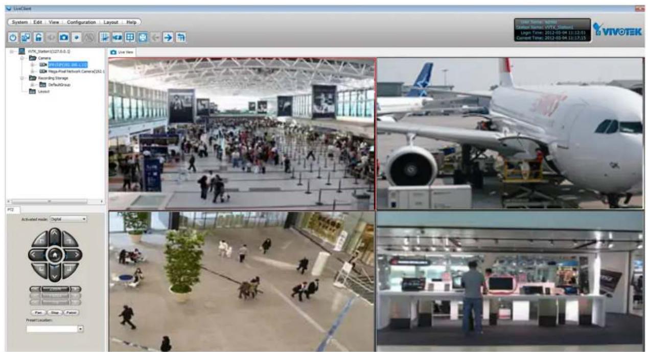
VAST Server
Activating the VAST Server
VAST Server is a service program that will run automatically when your NVR system starts. The VAST server manages video recording, live view monitoring, and other related surveillance functions.
How to Stop/Reboot the Server
Please follow the steps below to stop/reboot the server:
- Click on the VAST Service shortcut on the Control Center desktop.

- There are 3 options: Start Service, Stop Service, and Restart Service. It's selectable using the buttons below. Stop Service can be used to promptly stop a recording task or access from a remote computer.



LiveClient Configuration
Opening the LiveClient Interface and Logging in
VAST LiveClient allows you to monitor live video from cameras managed by the NVR; it is also the main access to the server's functional control.
Double-click on the LiveClient shortcut on the desktop to open the LiveClient utility:
- The login box will prompt. Provide the default User Name and password as admin and admin.
- Click on the Login button to continue.

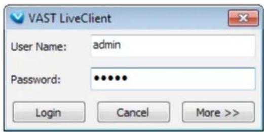
- The VAST LiveClient monitoring window will prompt.

NOTE:
Available functions of the LiveClient program will be enabled according to the privileges granted for your login account. For more details about user account, please refer to How to Manage User Accounts on page 57.
LiveClient User Interface
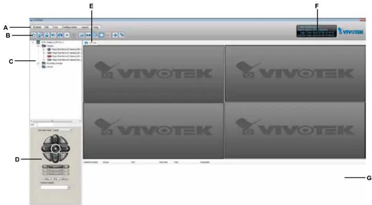
A. Menu bar
B. Quick access bar
C. Hierarchical management tree
D. Camera control panel (PTZ / Two way audio / Instant Playback control panel)
E. Live view window F. Status panel G. Event window
Menu Bar
| System | Edit | View | Configuration | Layout | Help |
| Menu Item Drop-down Options | |
| System | Lock / Enable Click On Image (Disable Click On Image) / E-map / Launch Playback / Logout / Exit |
| Edit | Manually Begin Recording (Stop Manual Recording) / Snapshot / Record to EXE / Snapshot Zoomed Image / Find |
| View PTZ Panel | / Two Way Audio Panel / Event Window / Full Screen / Minimize |
| Configuration | Camera Management (Insert Camera / Update Camera / Delete Cameras / Batch Insert Cameras / Camera Configuration) / User Management / Association Management / Event Management / Station Settings (General Settings / Network Settings / Recording Storage Settings / Recording Schedule Settings / Scheduled Backup Settings / Server Settings / Relay Settings) / Client Settings (Snapshot Settings / Recording Settings / View Settings / General Settings / Joystick Settings / PiP Settings) / Video Enhancement (Basic Image Adjustment / Defog) |
| Layout Start Rotating | (Stop Rotating) / Save to / Delete / Choose / Patrol |
| Help About | |
Status Panel
| User Name: adminStation Name: ND8401Login Time: 2012-12-20 16:05:54Current Time: 2012-12-20 16:08:06 | User NameStation Name (IP Address)Login Time (yyyy-mm-dd hh:mm:ss)Current Time (yyyy-mm-dd hh:mm:ss) |
Quick Access Bar

Icon Function Description


Exit Exit the system
Logout Log out from the current station
Lock Click to Lock the system for security concerns (
Volume Adjust the audio volume of the current video (Mute)
Snapshot Capture pictures from the focus live video cell
Record to Media Record media in EXE/3GP/AVI format (
Alert Sound Silence a triggered alarm when an event occurs, e.g., a DI is triggered.
Adjust SVC Level Dynamically adjust the SVC control over frame rates
Remove All Connections Remove all live videos from the live view window
Layout Change the layout of the live view window
Full Screen Maximize the live video cell
Page Up Switch to the previous live view page
Page Down Switch to the next live view page
Start / Stop Rotating Start or stop live view layout rotating


Recording Media)

NOTE:
Some buttons will be disabled if the selected devices do not support the related functions.
Live Video Monitoring Window
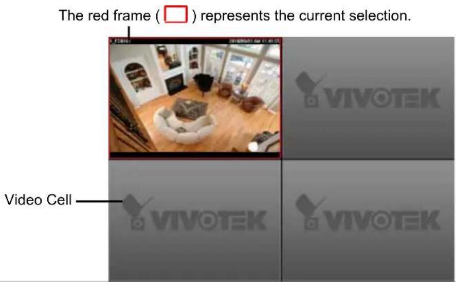
The "VIVOTEK" logo is displayed where no camera has been assigned to a video cell.
Hierarchical Management Tree
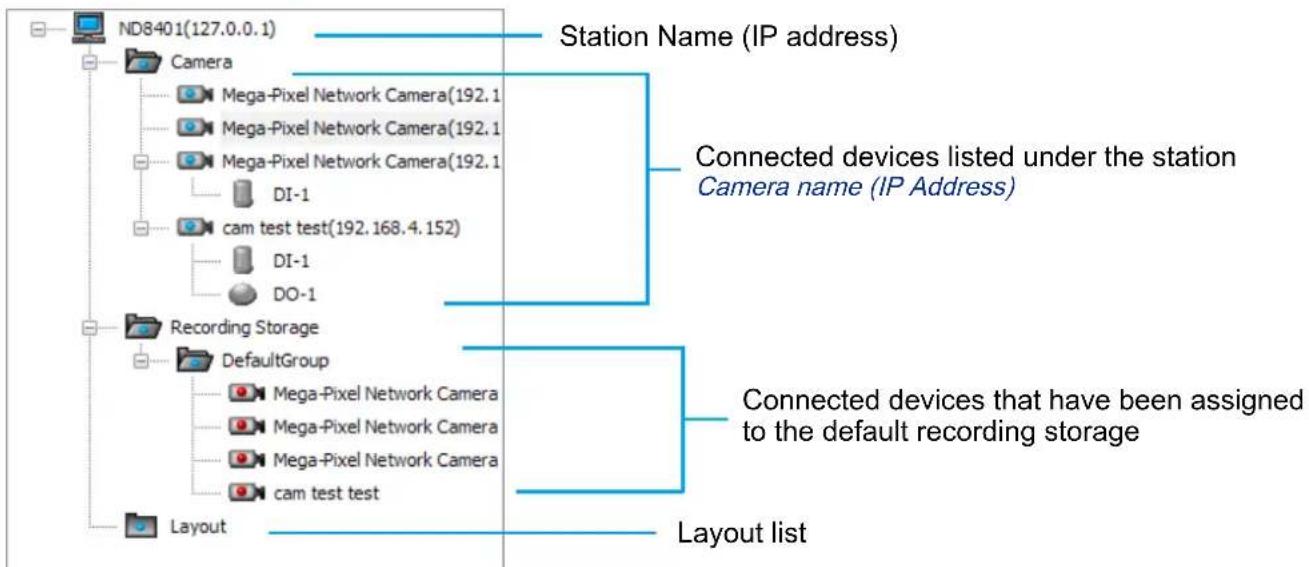
flowchart
graph TD
    A["ND8401(127.0.0.1)"] --> B["Camera"]
    B --> C["Mega-Pixel Network Camera(192.1)"]
    B --> D["Mega-Pixel Network Camera(192.1)"]
    B --> E["Mega-Pixel Network Camera(192.1)"]
    B --> F["DI-1"]
    B --> G["cam test test(192.168.4.152)"]
    G --> H["DI-1"]
    G --> I["DO-1"]
    J["Recording Storage"] --> K["DefaultGroup"]
    K --> L["Mega-Pixel Network Camera"]
    K --> M["Mega-Pixel Network Camera"]
    K --> N["Mega-Pixel Network Camera"]
    K --> O["cam test test"]
    P["Layout"] --> Q["Station Name (IP address)"]
    Q --> R["Connected devices listed under the station Camera name (IP Address)"]
    R --> S["Connected devices that have been assigned to the default recording storage"]
    S --> T["Layout list"]
| Icon Description | |
| A station (The NVR running the VAST Server) | |
| VIVOTEK fixed network cameraRed dot signifies that the camera is recording. | |
| VIVOTEK PTZ network cameraRed dot signifies that the camera is recording. | |
| VIVOTEK dome network cameraRed dot signifies that the camera is recording. | |
| VIVOTEK fisheye network cameraRed dot indicates that the camera is recording. | |
| VIVOTEK video serverRed dot signifies that the video server is recording. | |
| Digital input on / off | |
| Digital output on / off | |
| A layout of the live monitoring window | |
| A station that's not able to be connected currently. | |
| A device that's not able to be connected currently. |

NOTE:
A Logical Tree will be available with the LiveClient console separately installed on a remote PC. The Live Client instance will be available in the Software CD that comes with the NVR system (rev. 1.7.x). That particular edition allows the NVR and cameras under it to be listed with other VAST server configurations.
Camera Control Panel
Pan/Tilt/Zoom (PTZ) Control Panel
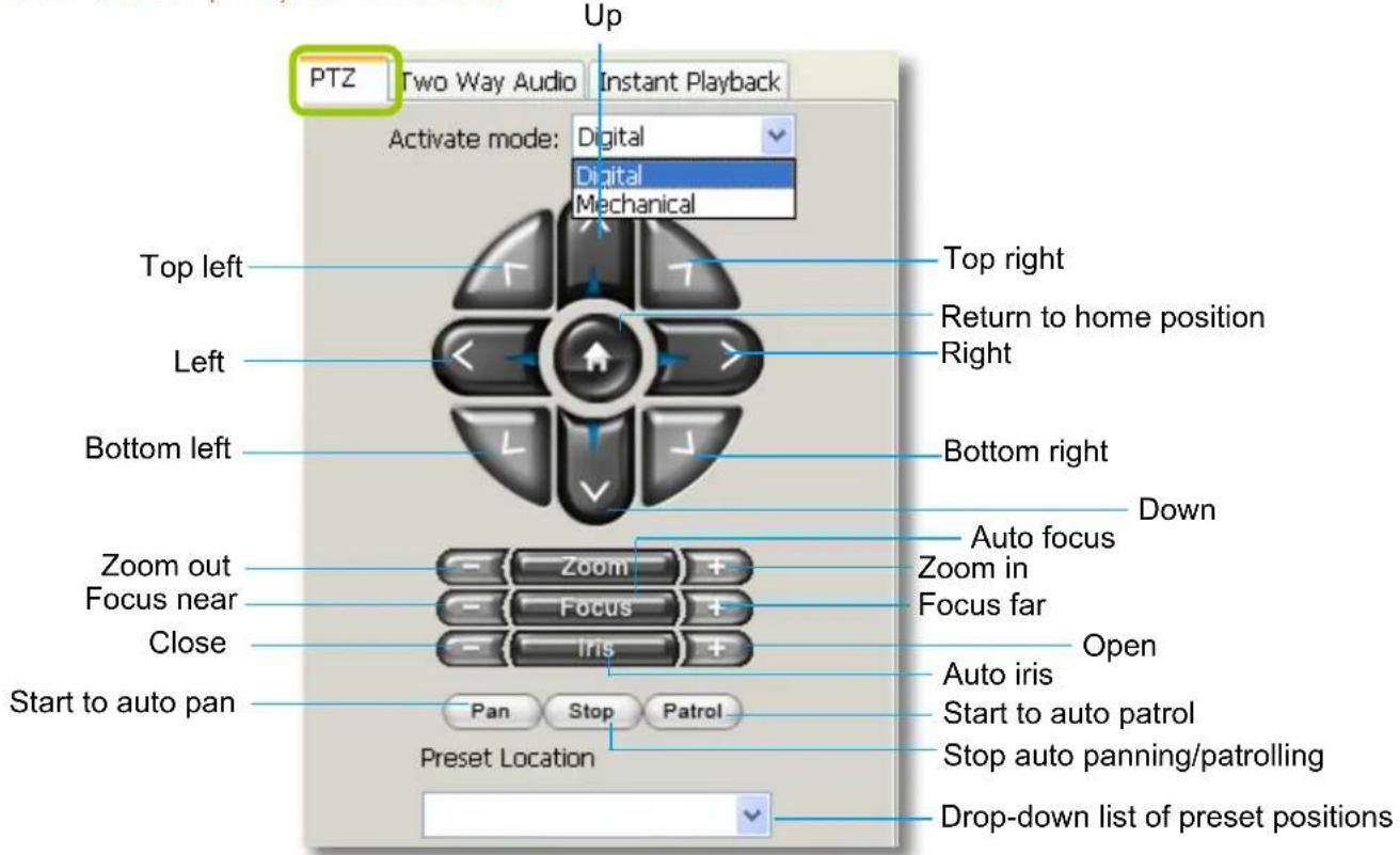

NOTE:
There are two types of PTZ control: Digital (E-PTZ for megapixel cameras) and Mechanical (PTZ cameras or fixed cameras with camera control via RS-485). If the connected cameras support PTZ/E-PTZ function, the PTZ option(s) will appear on the drop-down list. For detailed camera control settings, please refer to the user's manual of VIVOTEK network camera.
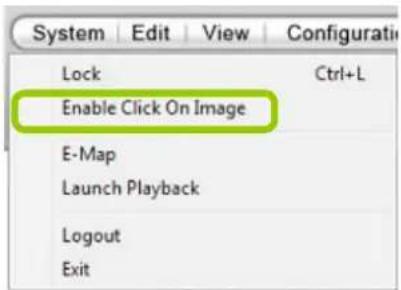
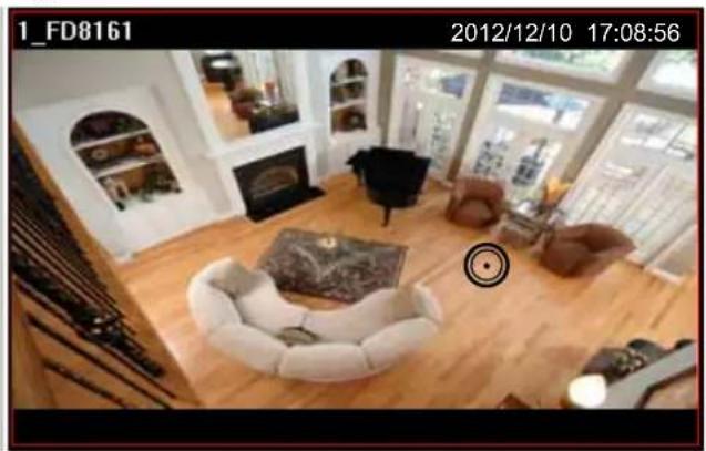
- Click System > Enable Click On Image to use the mouse for the control of the PTZ and e-PTZ functions in the video cells for linked cameras. An icon ⚙ will appear in the video cell as shown below.
natural_image
Interior view of a modern living room with white sofas, fire extinguisher, and large windows (no visible text or symbols)■ You can control the PTZ function through a joystick as well. For more information regarding to the joystick configuration, please refer to instructions on page 139.
Two Way Audio Control Panel
The two way audio function allows the user to remotely communicate with people nearby the network camera.
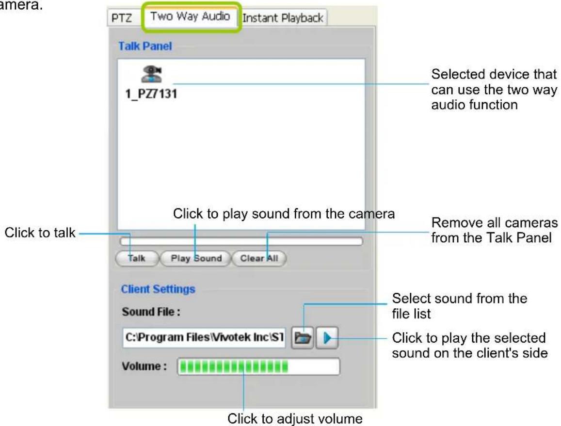

NOTE:
■ For detailed information about How to Use the Talk Panel, please refer to page 113.
■ Only cameras that come with the two way audio function can be added to the Talk Panel.
■ The Language selection menu has been moved to the Setup Wizard.
Event Window
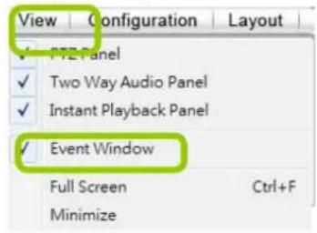
Click View > Event Window to insert a window showing the real-time information for event triggers. If you want to hide this window, deselect this option on the menu bar.
| Instant Playback: | Source | Time | Time Zone | Type | Description |
| 04_IP7251_34 | 2012-07-30 15:18:57.122 | +08:00 | IVA - Moving Object | ||
| 03_IZ7151_33 | 2012-07-30 15:10:21.640 | +08:00 | Motion - Window 1 | 22% | |
| 03_IZ7151_33 | 2012-07-30 15:09:37.594 | +08:00 | Motion - Window 1 | 13% | |
| 03_IZ7151_33 | 2012-07-30 15:09:36.527 | +08:00 | Motion - Window 2 | 21% | |
| 03_IZ7151_33 | 2012-07-30 15:09:35.259 | +08:00 | Motion - Window 3 | 21% | |
| 04_IP7251_34 | 2012-07-30 15:09:30.923 | +08:00 | IVA - Moving Object | ||
| 04_IP7251_34 | 2012-07-30 15:09:28.521 | +08:00 | IVA - Moving Object | ||
| 04_IP7251_34 | 2012-07-30 15:09:27.254 | +08:00 | IVA - Moving Object | ||
| 04_IP7251_34 | 2012-07-30 15:09:12.844 | +08:00 | IVA - Moving Object | ||
| 04_IP7251_34 | 2012-07-30 15:09:11.710 | +08:00 | IVA - Moving Object | ||
| 04_IP7251_34 | 2012-07-30 15:09:09.893 | +08:00 | IVA - Moving Object |
Event Window
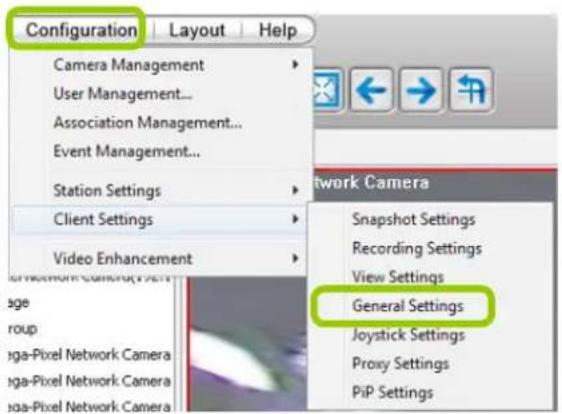
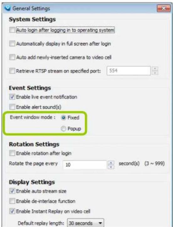
The default event window is fixed on the bottom of the LiveClient. If you want to change the event window as a popup page, please click Configuration > Client Settings > General Settings to switch the modes.
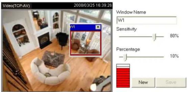
■ The Type field in the event window shows the event category and another field Description displays the percentage of motion in the detection window. You can open an individual web console with the camera (left-click to select, right-click to oepn Camera Setting) to configure Motion Detection and set the percentage. ☑ Enable motion detection

NOTE:
For more information about DI/DO settings, please refer to Association Management on page 71.
Instant Playback (on Remote LiveClient)
Instant Playback is available on a remote LiveClient console. Check View > Instant Playback to open the window on the panel. The entries are the short recordings made from triggered events.
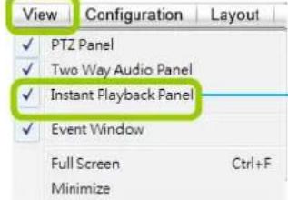
Uncheck this item if you want to hide this window.


| Instant Playback | Source | Time | Time Zone | Type | Description |
| 0 | 04_IP7251_34 | 2012-07-30 15:18:57.122 | +08:00 | IVA - Moving Object | |
| 0 | 03_IZ7151_33 | 2012-07-30 15:10:21.640 | +00:00 | Motion - Window 1 | 22% |
| 0 | 03_IZ7151_33 | 2012-07-30 15:09:37.594 | +00:00 | Motion - Window 1 | 13% |
| P | 03_IZ7151_33 | 2012-07-30 15:09:36.527 | +08:00 | Motion - Window 2 | 21% |
| 0 | 03_IZ7151_33 | 2012-07-30 15:09:35.259 | +08:00 | Motion - Window 3 | 21% |
| 0 | 04_IP7251_34 | 2012-07-30 15:09:30.923 | +08:00 | IVA - Moving Object | |
| 0 | 04_IP7251_34 | 2012-07-30 15:09:28.521 | +00:00 | IVA - Moving Object | |
| 0 | 04_IP7251_34 | 2012-07-30 15:09:27.254 | +08:00 | IVA - Moving Object | |
| P | 04_IP7251_34 | 2012-07-30 15:09:12.844 | +08:00 | IVA - Moving Object | |
| P | 04_IP7251_34 | 2012-07-30 15:09:11.710 | +08:00 | IVA - Moving Object | |
| P | 04_IP7251_34 | 2012-07-30 15:09:09.992 | +08:00 | IVA - Moving Object |
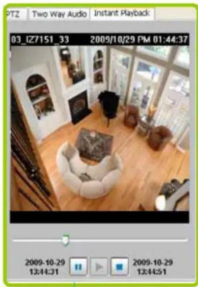
Instant Playback Window with a slide bar, play, pause, and stop function
The recorded media that was triggered by an event will be indicated by an icon.
You can double-click an event on the list to playback the recorded video. Each event contains a video clip of about 20-seconds in length. (The default recording data of an event is 20 seconds. For more information about event recording, please refer to page 87.)
Instant Replay (on Remote LiveClient)

If a camera is currently recording to the NVR, then a Replay button will be available at the left corner of its view cell. This allows you to immediately retrieve the video recording in last 30 seconds.
The Instant Replay function enables you to quickly retrieve videos of what has just happened (20 seconds to 15 minutes ago), without the need to open the Playback utility for the past videos.

NOTE:
The Switch Monitor button is available on an independent LiveClient instance installed on a remote PC. For a direct connection with the NVR, this button is not available.
Prerequisites for Instant Replay:
- The function is enabled by default, only available on a LiveClient installed on a PC.
- There must be recorded videos of the immediate past. If the video streams from a camera were not recorded, you can not retrieve videos using the Instant Replay function.

NOTE:
- When using the Instant Replay function and you change the stream number on a video cell, the Instant Replay will be interrupted.
- The Instant Replay will also be interrupted when the time comes for a rotation of Live View pages. For example, if you have multiple Live View pages and you set up a rotation of these pages by every 10 seconds, page swap (rotation) still has a higher priority even if you are viewing the Instant Replay.
How to Use:
- On a selected view cell, mouse over to the lower left corner. A Replay icon will appear.
- Click on it to display the Replay control bar. Click on the play button.

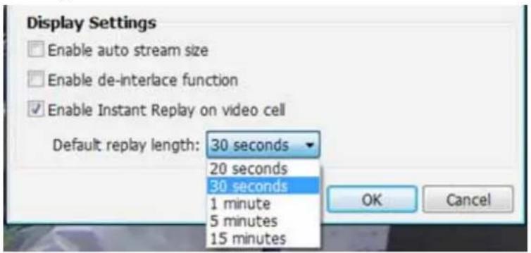
- The default queue length is 30 seconds. You can click on the number on the right to change the queue length.
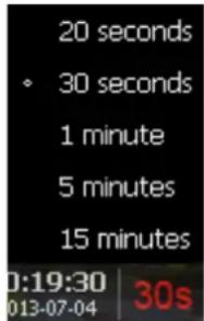
The queue length configuration stays with the view cell, and it will not go unless you remove and insert the camera again.
- To stop the Replay and return to the Live View, click on the Return to Live button.

- On a Replay view cell, you can apply the same Snapshot, Print, Single view and Full screen control as those on a normal view cell. You can also right-click to display the Display Mode and Video Enhancement functions.
Click and drag the playhead to skip or move to a different point in time on the playback.

An active Replay view cell is indicated by the Replay text indicator and the time of occurrence of the current playback.
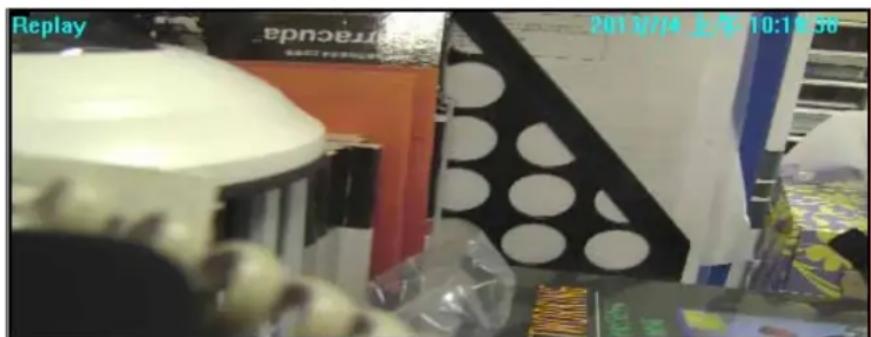
To change the default Replay settings, open the Configuration > Client Settings > General Settings menu.
Audio Control

The audio function will be enabled if the device is equipped with an internal or external microphone. For detailed audio control settings, please refer to page 138.
How to Manage Devices (Cameras)
Please follow the steps below to open the Camera Management window:
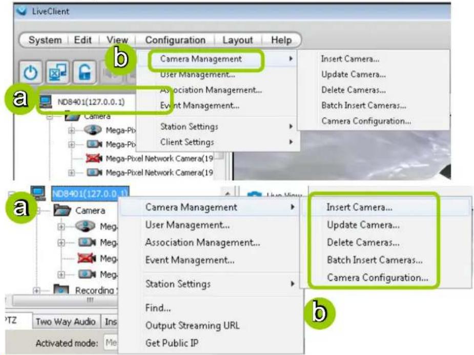
a. Select the station from the hierarchical management tree.
b. Click Configuration > Camera Management on the menu bar (or right-click the station, then select Camera Management).
c. Then you can choose to insert, update, delete, or batch insert cameras.
Insert Cameras
Please follow the steps below to add devices (cameras or video servers) to a station:
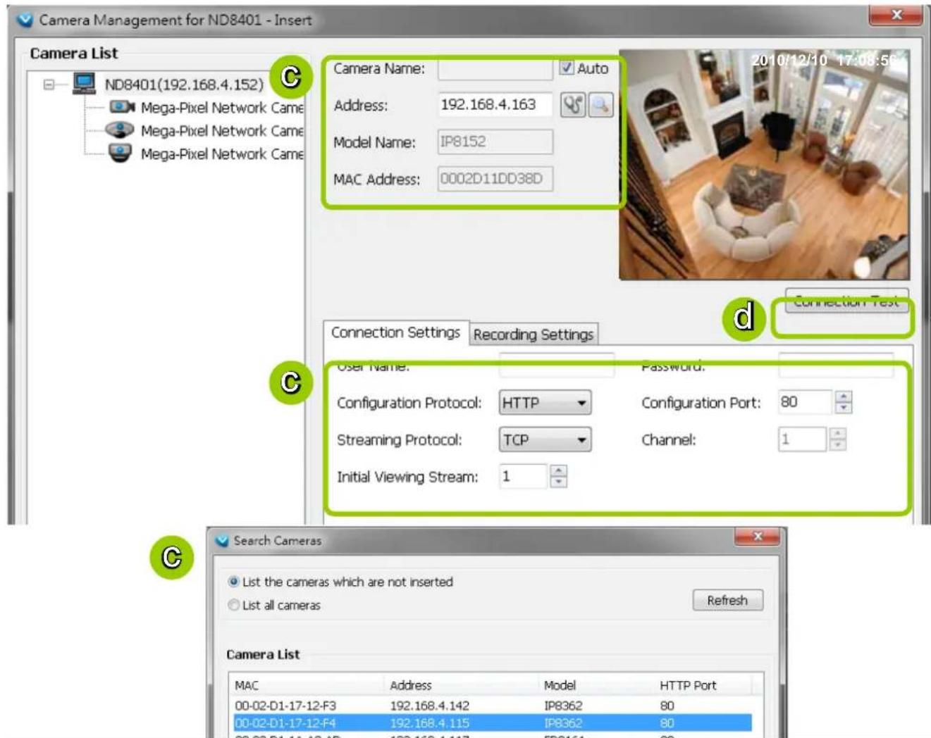
a. Click Configuration > Camera Management > Insert Camera on the menu bar (or right-click the device/station, then select Camera Management > Insert Camera).
b. The Camera Management - Insert window will pop up. The device tree managed by the station will be displayed in the Camera List window on the left.
c. Enter the Camera Name, IP address (or you can enter an IP address and check Auto to get a camera name automatically) and configure the Connection Settings.
■ If the camera is on the LAN, you can click Search Camera to detect all VIVOTEK network cameras on the LAN. A Camera List window will pop up and show a list of detected cameras on the LAN. On the top of Camera List window, you can select "List the cameras which are not inserted" or "List all cameras". The items listed below will then change accordingly. You can click Mac, IP Address, Model, HTTP port to sort the items. Then select a camera from the list to insert to the station.
■ The streaming protocol determines how the live video stream is sent from the camera to the local computer. Please refer to the note on the next page for a detailed description of each transmission protocol. Specify the recommended live monitoring stream for the device. If you want to change the live viewing stream, please refer to the next page to update the camera settings. Or you can right-click the desired view cell, then select a desired stream. Please refer to Dual / Multiple Streams on page 53 for a detailed illustration.
- Click Detect Model to detect the device. The Model Name and MAC Address of the device will automatically be displayed in the respective fields if the connection is successful.
d. If you want to make sure you are connected to the target device, click Connection Test to preview the live video from the device.

NOTE:
If you want to use "HTTPS Port", please enable the HTTPS settings on the configuration page of a web console with a Network Camera. Refer to the camera's User Manual for details.
■ The characteristics of each protocol are shown in the following table:
Protocol Description
| UDP | UDP uses a simple transmission model without implicit hand-shaking dialogues for guaranteeing reliability, ordering, or data integrity. Thus, UDP provides an unreliable service and data grams may arrive out of order, appear duplicated, or go missing without notice. This protocol allows for almost real-time audio and video streams. However, network packets may be lost due to network burst traffic and images may be obscured. Activate UDP connection when occasions require time-sensitive responses and video quality is less important. |
| TCP | TCP provides the service of exchanging data reliably directly between two network hosts, whereas IP handles addressing and routing message across one or more networks. In particular, TCP provides reliable, ordered delivery of a stream of bytes from a program on one computer to another program on another computer. This protocol guarantees the delivery of streaming data and thus provides better video quality. The downside with this protocol is that the real-time effect is worse than that with UDP for a narrower bandwidth. |
| HTTP | HTTP is a networking protocol for distributed, collaborative, hypermedia information systems. It's the foundation of data communication for the World Wide Web. This protocol allows for the same quality as TCP and the users need not open a specific port for streaming under some network environment. Users inside a firewall can utilize this protocol to allow streaming data through. |
| HTTPS | This protocol enables authentication and encrypted communication over SSL (Secure Socket Layer), which protects streaming data transmission over the Internet on higher security level. |
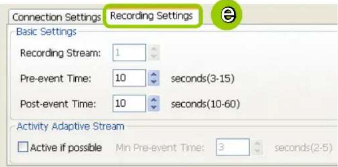
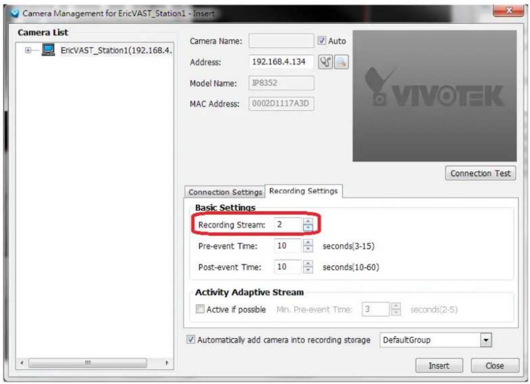
e. Configure Recording Settings:
- Recording Stream: By default, the stream source of the recording stream is stream 1, if you want to change it later on, please refer to the previous page to update the camera settings.
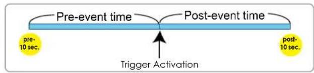
■ Pre-event time: Enter a number to decide how much time to record before an event is triggered.
■ Post-event time: Enter a number to decide the duration of recording after an event is triggered.
flowchart
graph LR
    A["pre-event time"] --> B["post-event time"]
    B --> C["Trigger Activation"]
    style A fill:#f9f,stroke:#333
    style B fill:#bbf,stroke:#333
    style C fill:#dfd,stroke:#333

NOTE:
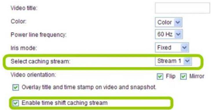
Please note that if you want to enable activity adaptive stream, we suggest you right-click the camera on the heirarchical management tree > Camera Settings to open a management session. Move to Configuraion > Media > Audio and Video to activate "Time Shift Cache Stream" on the camera and select a stream source. This will help record complete pre-event recording.
Note that some of VIVOTEK's latest cameras have this function enabled by default. No configuration option is needed on the camera.
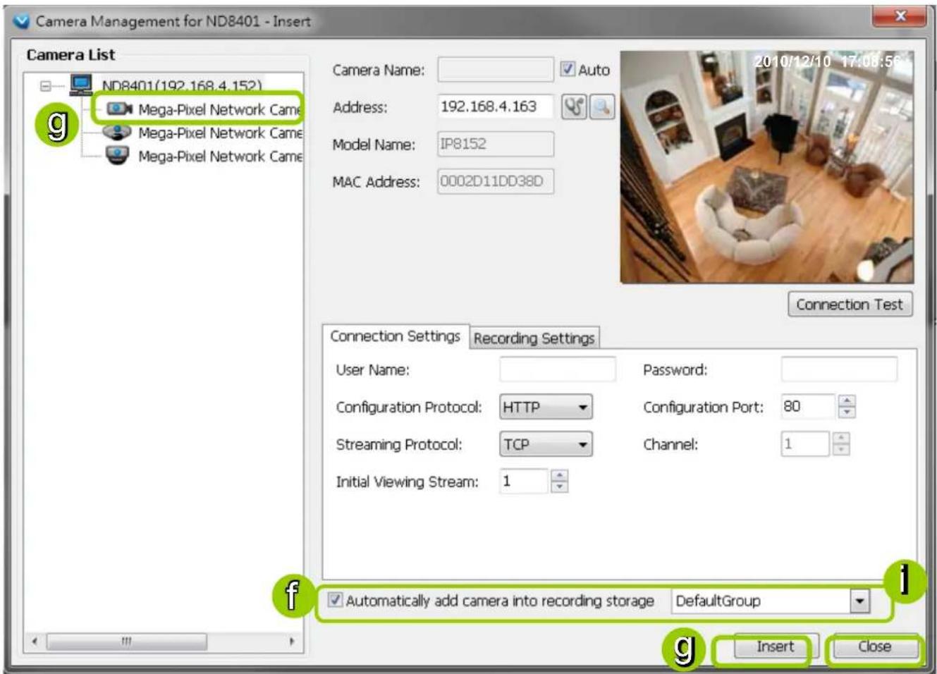
f. The device will automatically be assigned to the default Storage Group. Deselect the item if you want to cancel this setting.
g. When all settings are completed, click Insert to add the device to the station. The device will be displayed under the Camera List on the left.
h. To insert more devices to the station, repeat the above steps.
i. When completed, click Close to exit the camera management window.
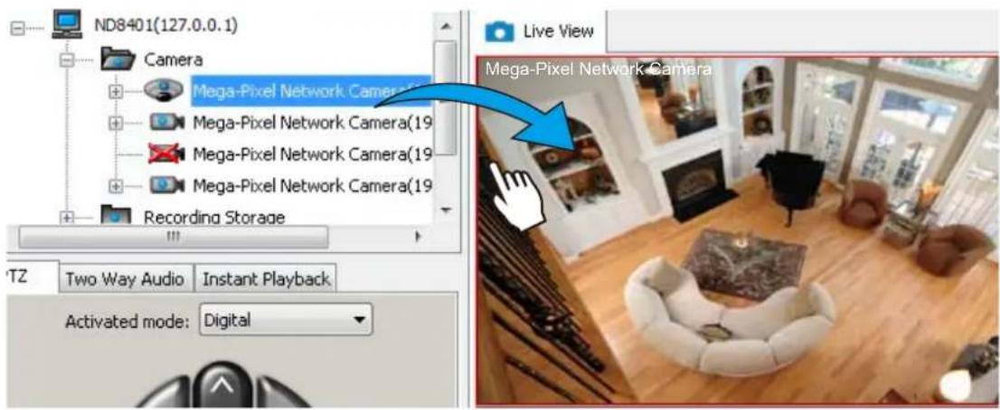
j. Return to the main window, you will find the newly-inserted devices listed under the VAST station and then you can click and drag cameras into the live cells.
Enable SVC
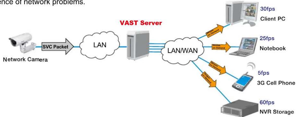
If the camera to-be-added supports the latest SVC (Scalable Video Coding) feature, select the SVC checkbox to enable the related control. The SVC feature enables streaming of videos for multiple clients from one single set of layered IP packets. Designed for saving bandwidth and CPU load on client stations, the frame rate of a video stream appearing through a view cell can be individually adjusted. This feature applies when an administrator experiences unstable video streaming due to the lack of network bandwidth, less-than-ideal hardware, or during an occurrence of network problems.
flowchart
graph LR
    A["Network Camera"] -->|SVC Packet| B["LAN"]
    B --> C["VAST Server"]
    C --> D["LAN/WAN"]
    D --> E["Client PC 30fps"]
    D --> F["Client PC 25fps"]
    D --> G["Notebook"]
    D --> H["3G Cell Phone 5fps"]
    D --> I["NVR Storage 60fps"]
    E --> J["Stream on Demand"]
    F --> K["Stream on Demand"]
    G --> L["Stream on Demand"]
    H --> M["Stream on Demand"]
    I --> N["NVR Storage"]
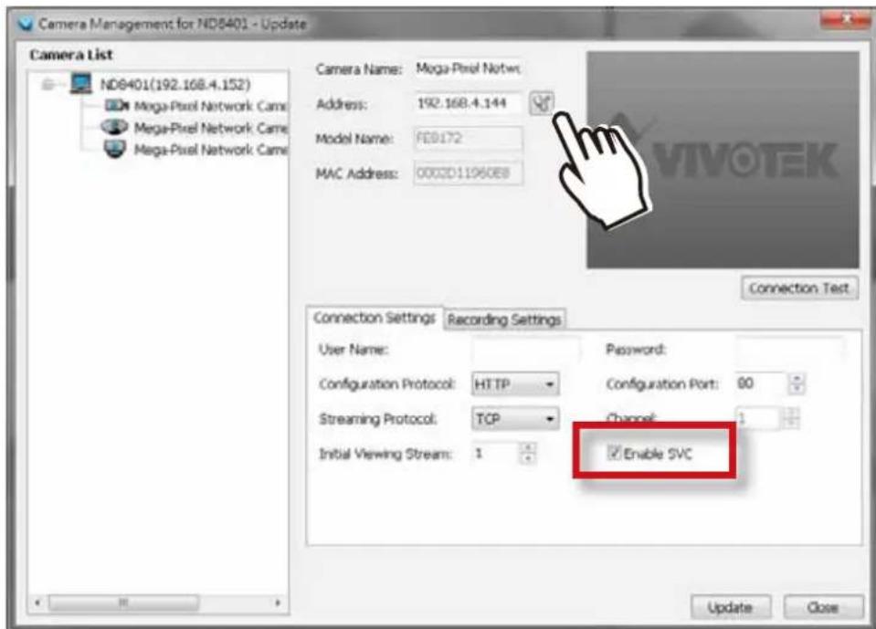
The VAST server automatically negotiates with a camera and determines whether a network camera comes with the SVC feature. The SVC checkbox appears if the network camera supports the feature. The same checkbox also appears in the Batch Insert Cameras window.
To configure the SVC-related feature:
- When inserting a new camera into your configuration, click on the Detect Model button.
- select the Enable SVC checkbox.
- Right-click on the view cell of an SVC-enabled camera. Select SVC fps adjust bar.
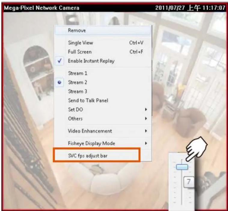
- A slide bar will appear above the view cell. Click and drag the slide bar. A numeric indicator will display the current selection. See below for the frame rates represented by the numeric indicator.
| Indicator Frames per second (fps) | |
| Maximum 30 | |
| 7 | 26 |
| 6 | 22 |
| 5 | 18 |
| 4 | 12 |
| 3 | 8 |
| 2 | 4 |
| 1 | 1 |
| Minimum 1/4 | |

NOTE:
The SVC feature only applies to video streams using VIVOTEK's proprietary SVC compression format. It is not applicable to MPEG-4 streams. Please refer to Configuration -> Media -> Video for individual stream settings.
If you have multiple SVC-enabled cameras, you can enable a collective setting via the Adjust SVC level button on the tool bar. The frame rate selected here will then apply to all view cells on the VAST LiveClient console.
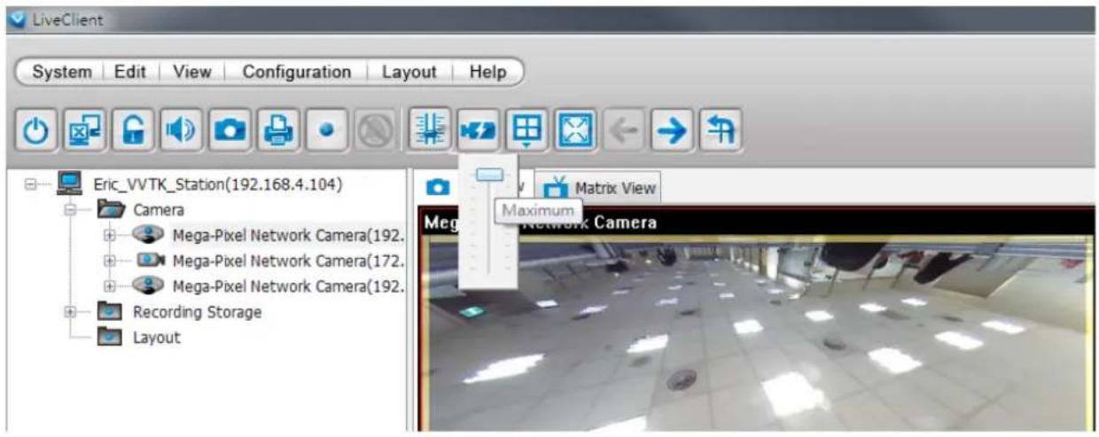
Please note that the SVC related setting can not take effect while the LiveClient station is running the Layout Rotation. Stop the layout rotation before configuring the SVC function.

NOTE:
While you save your bandwidth for live viewing, you can still record full-frame-rate video by changing the recording setting. For example, you can enable resource-saving SVC on stream #1 and configure stream #2 to be recorded with full details, in terms of frame size, frame rate, and video quality. Please note that you should use the Constant Bit Rate methodology to limit the size of recording stream to 6Mb per second.
Update Devices
Please follow the steps below to update a device via Camera Management window:
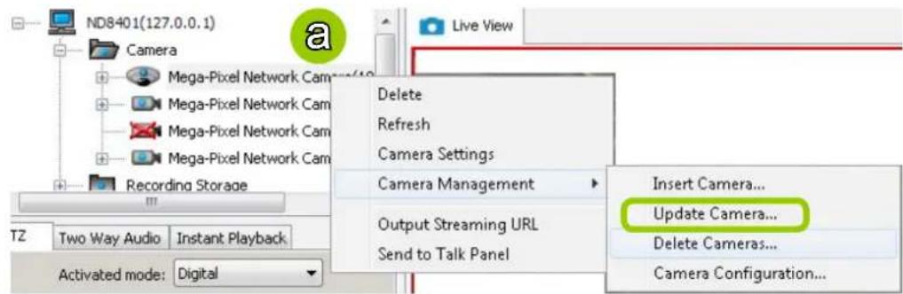
a. Click Configuration > Camera Management > Update Camera on the menu bar (or right-click the device/station, then select Camera Management > Update Camera).
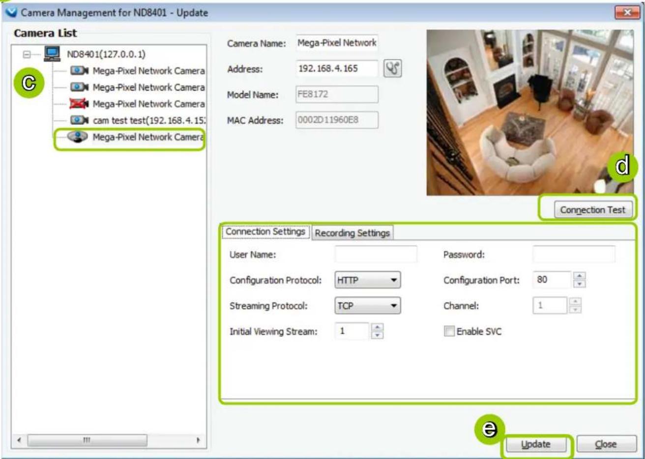
b. The Camera Management - Update window will pop up. The device tree managed by the station will be displayed in the Camera List on the left.
c. Select a device from the list you want to update. Its related information will automatically be displayed in the corresponding fields in the Camera Management window. Then you can modify Connection Settings and Recording Settings of the device.
d. After modifying the settings, you can click Connection Test to preview the live video from the device.
e. When all settings are completed, click Update to enable the settings.

Delete Devices from the Station
■ Delete a device:
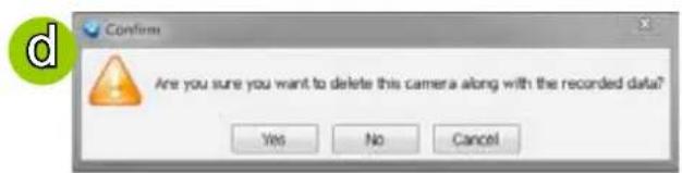
Right-click the device on the device tree, then select Delete. A dialog box will pop up. Click Yes to delete the device along with the recorded data; click No to delete the device but retain the recorded data; click Cancel to cancel the delete action.
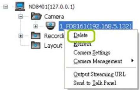
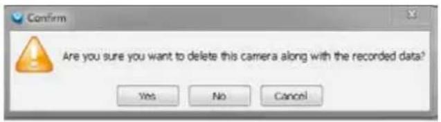
■ Delete more than one device at a time:
a. Click Configuration > Camera Management > Delete Cameras on the menu bar (or right-click the device/station, then select Camera Management > Delete Cameras).
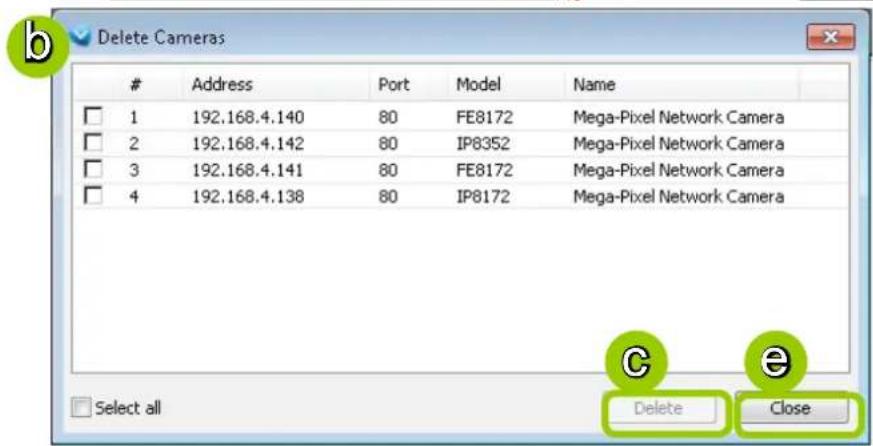
b. The Delete Cameras window will pop up.
c. Select the devices you want to delete from the list, then click Delete.
d. A dialog box will pop up. Click Yes to delete the device along with the recorded data; click No to delete the device but retain the recorded data; click Cancel to cancel the delete action.
e. When completed, click Close to exit the Delete Cameras window and return to the main window. The deleted device will disappear from the station.
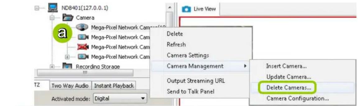
Batch Insert Cameras
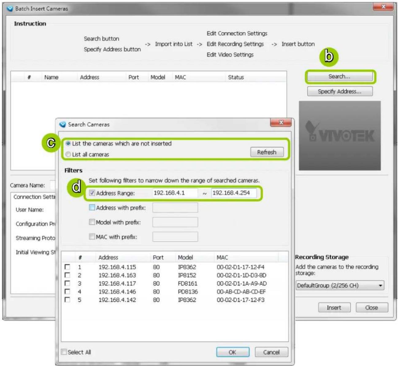
Batch insert is a very useful function that allows user to search, filter, and import a row of devices that are in the same LAN to an NVR station. Basic settings can also be applied to those inserted devices simultaneously.
Please follow the steps below to batch insert devices to the station:
a. Click Configuration > Camera Management > Batch Insert Cameras on the menu bar (or right-click the station, then select Camera Management > Batch Insert Camera).
b. The Batch Insert Cameras window will pop up. Then click Search to open the Search Camera window.
c. On top of the Camera List window, you can select "List the cameras which are not inserted" or "List all cameras". The items listed below will then change accordingly.
d. Use the 4 Filters to narrow down the range of the wanted cameras from the list.
■ IP Range: Key in a range of IP address to narrow down the list; the filter automatically applies after you fill in a correct IP range.
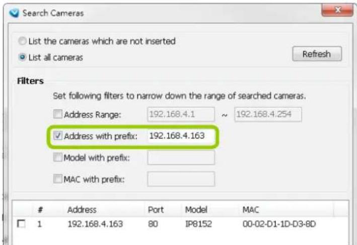
■ IP with prefix: Key in in the prefix of the IP address to narrow down the list.
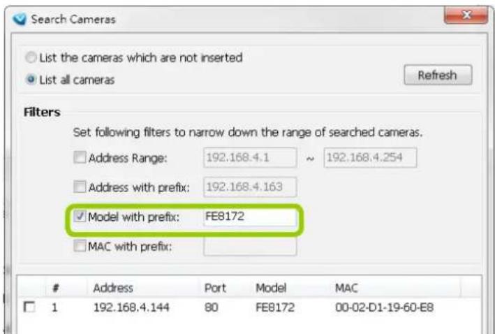
■ Model with prefix: The user can type in the prefix of the model name or the complete model name of the cameras to narrow down the list.
■ MAC with prefix: You can type in the prefix of the MAC address of the cameras to narrow down the list.
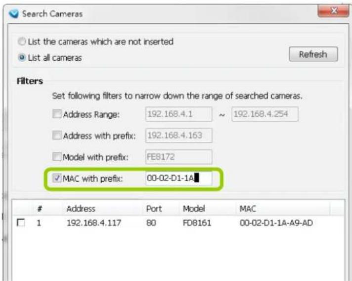
e. When the list is filtered, you can select the cameras one by one or check Select All to add them to the batch insert list. Then click OK to finish searching.
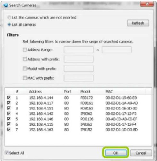
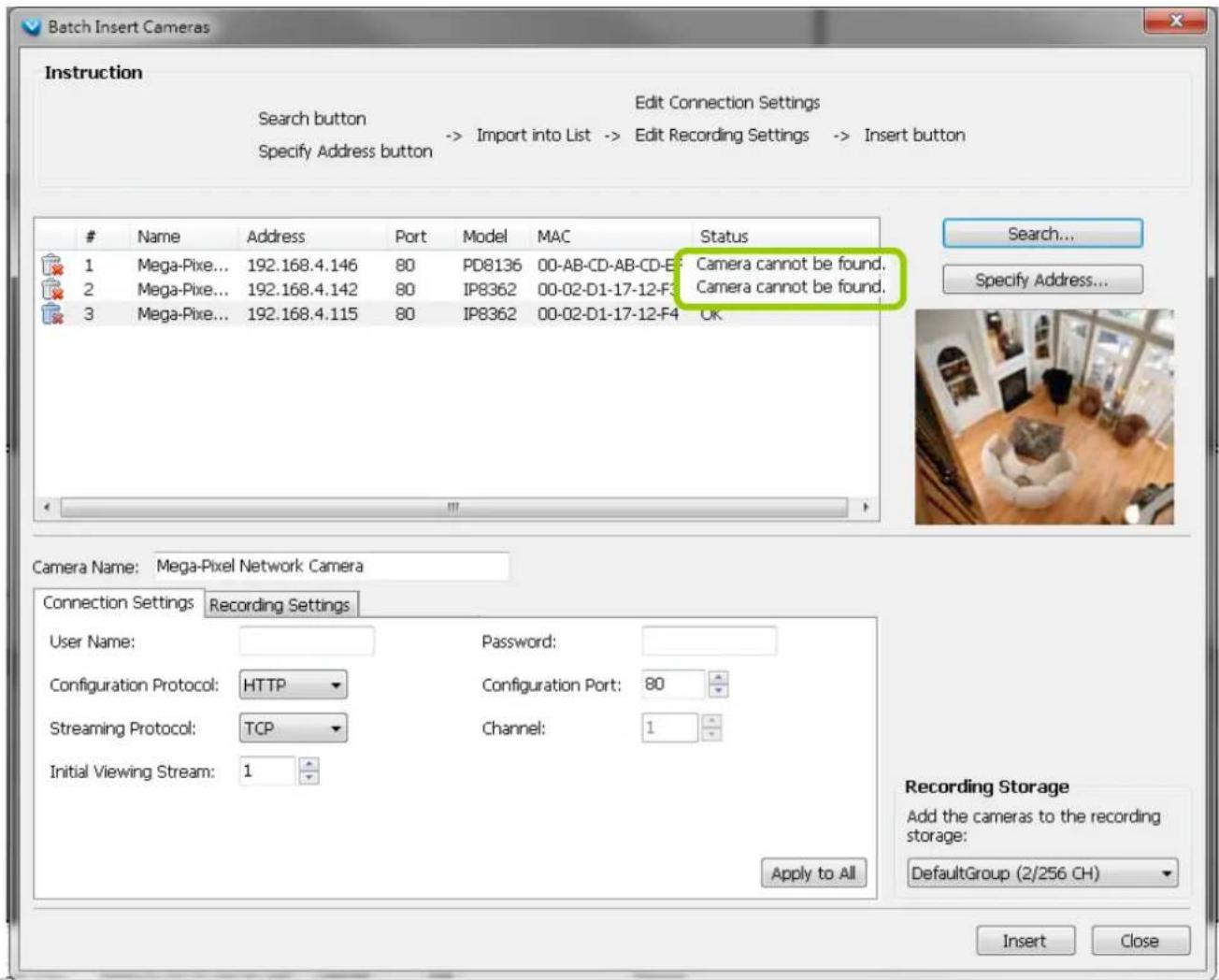
f. The selected cameras will be shown on the batch insert camera list with the camera information and the connection status. When you click on a camera, a snapshot will appear up on the right side for you to identify the cameras on the list. If you want to remove a camera from the list, click the trash can icon to delete it.
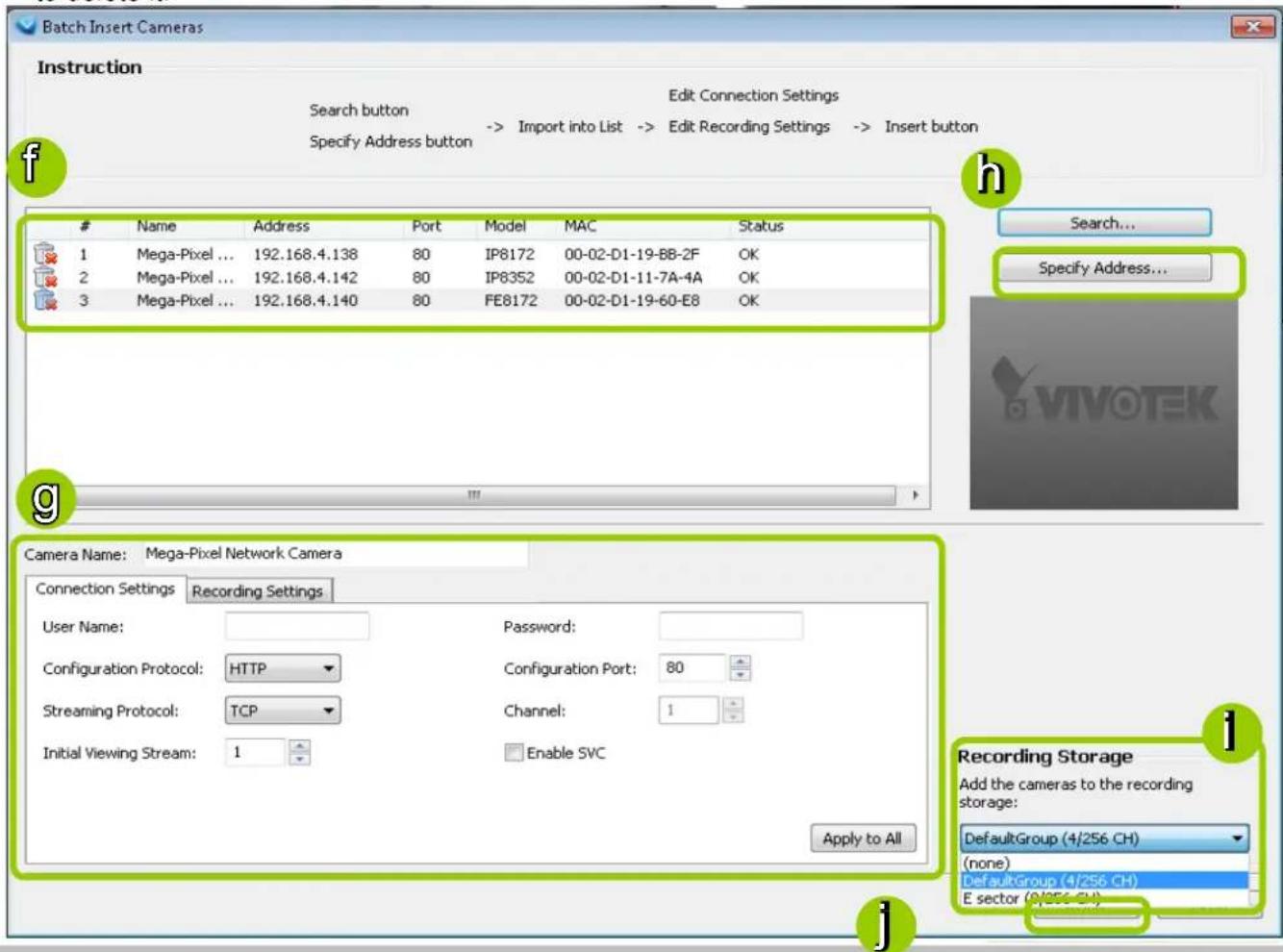
g. At the bottom of the window, there is a field for you to alter the camera settings including Connection Settings and Recording Settings. You can apply the new settings to each camera on the list, or click Apply to All to apply the same configurations to all the cameras. For more information about Connection Settings and Recording Settings, please refer to Insert Device on page 37 for detailed information.
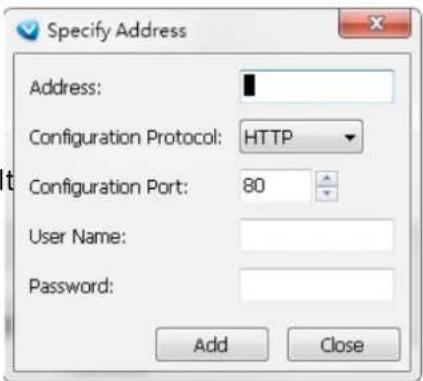
h. Specify host: If you want to add a camera to the list, click Specify Address to directly add a wanted camera. Click Add after filling in the correct information. The camera will be added to the list of the Batch Insert Camera window.
i. By default, all inserted devices will be applied to the default recording storage. Deselect the Add checkbox if you do not want to assign the selected devices to the default recording storage.
j. Click Insert when all the settings are done. Cameras will be added.

NOTE:
When you modify the camera settings, and when the connection information (Configuration Protocol and Configuration Port) does not match the current network environment, the camera will be disconnected and the status of the camera will become "Camera cannot be found" as shown below.
Camera Configuration
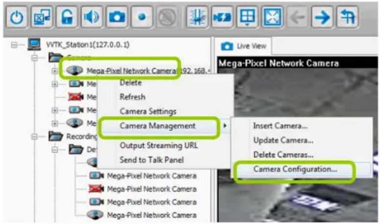
The Camera Configuration function group provides immediate access to the video streaming and other settings without the need to open a web console. The function group is accessed by selecting a camera on the device tree, and right-click to select Camera Management > Camera Configuration.
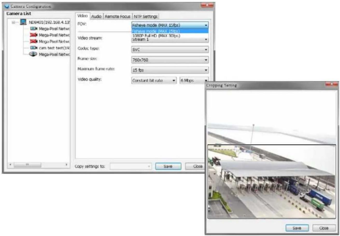
■ FOV (Field of View)
The FOV configuration is available for 5 megapixel cameras (such as FE8172, IP8372, and IP8172P), which allows you to crop a portion of the image captured by the sensor. The FOV setting applies in the scenario where you do not need all of the video a camera can capture. For example, when shooting a parking lot where the upper half of the image is the sky. Cropping a field of view can help save bandwidth and reduce the requirements for storage space.
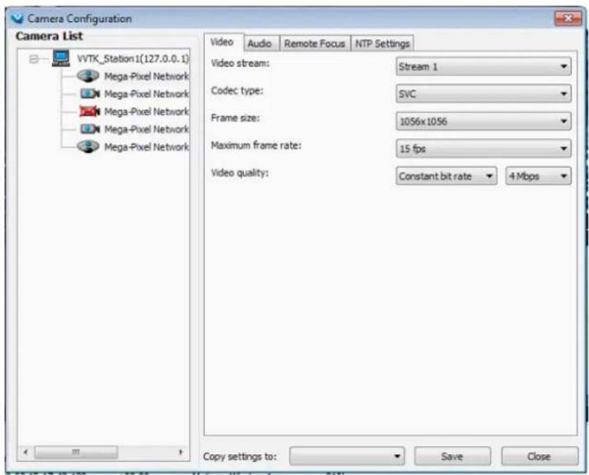
■ Video
This tabbed window provides access to the selection of the live view stream, its compression codec, frame size, max. frame rate, and video quality. Note that the Constant Bit Rate methodology can be used to ensure that the size of video stream does not exceed a preferred threshold, regardless of the complexity or the changes of pixels in the image. You should use a maximum of 1080P as frame size and 6Mbps as constant bit rate for video streams managed by this system.
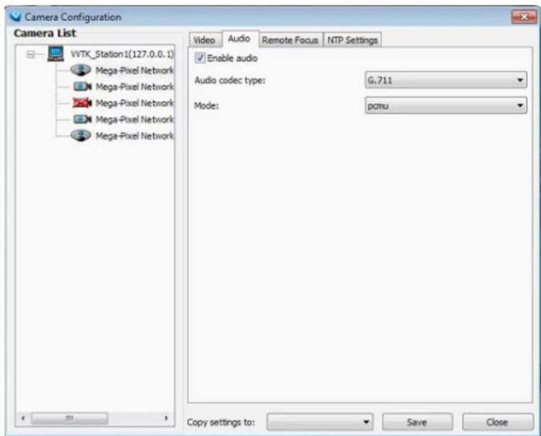
■ Audio
If audio feed is preferred, configure the audio codec type and operating mode in here.
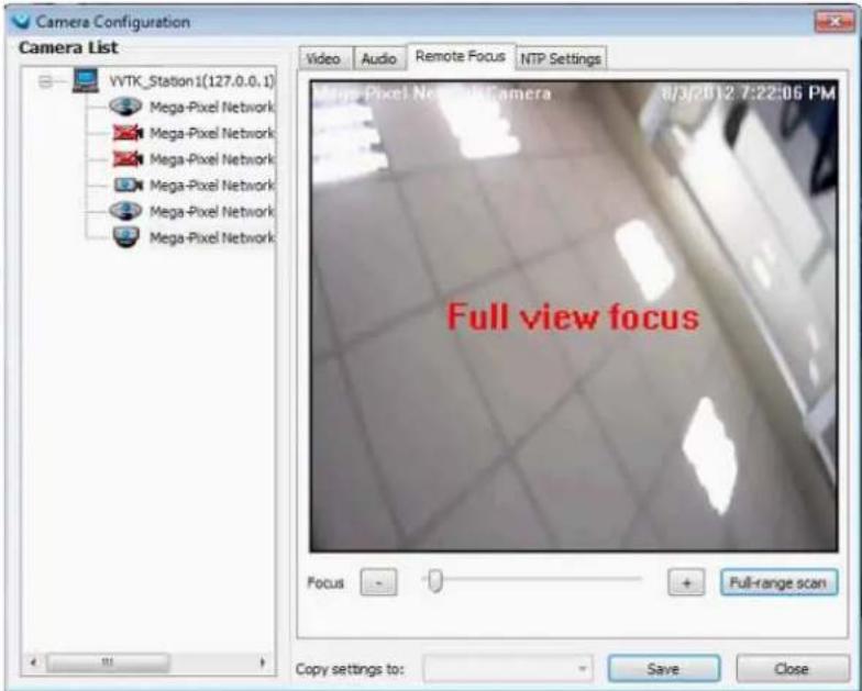
■ Remote Focus
For cameras supporting the remote focus feature, such as the FD8362E that comes with a motorized lens, this window provides finetune buttons and full-range scan function to help reach the best image focus.
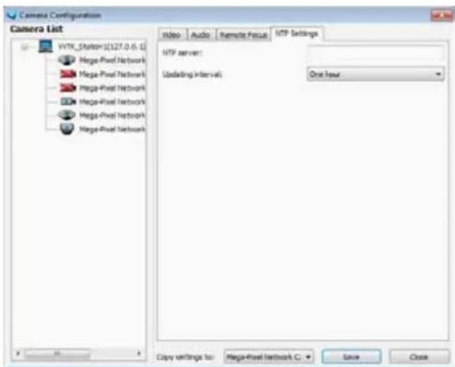
■ NTP Settings
If cameras' real time clocks are set to be synchronized with a time server, enter the NTP server's address or domain name and specify an Updating interval. If you select the "Synchronize camera time with system automatically" checkbox during the initial setup, the NTP server IP will be the NVR's IP.
Always remember to Save your configuration before leaving this window. You can also use the "Copy settings to" button below to duplicate your current settings to adjacent cameras.
View Live Videos
You should double-click on the target device or drag-and-drop the target device from the hierarchical management tree window to a video cell.
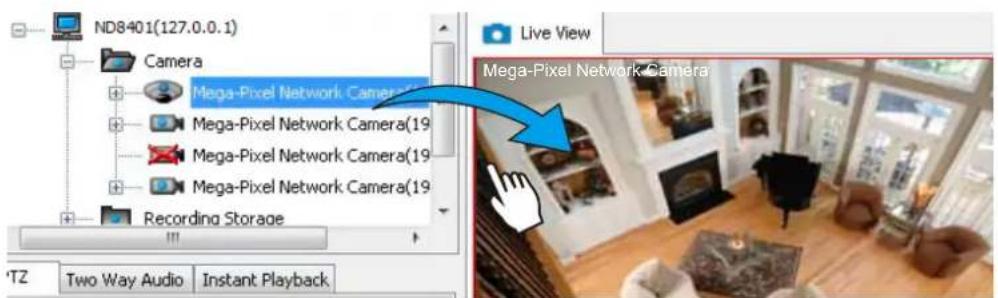
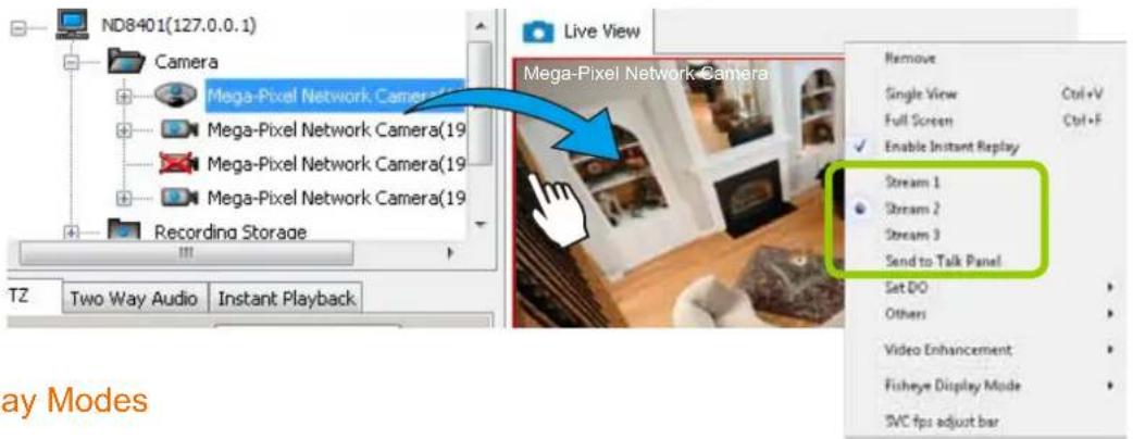
Dual / Multiple Streams
For multiple-stream devices, you can right-click on the focused view cell to select a stream. The NVR system automatically selects a video stream depending on the size of the current layout and view window. Normally it is not necessary to change the video stream.
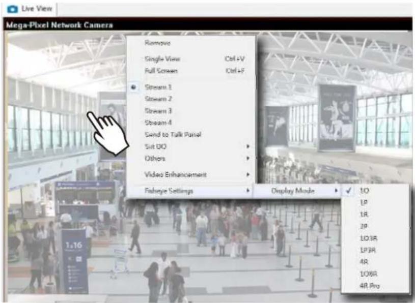
Fisheye Display Modes
By default, a round view is displayed when a fisheye camera is successfully connected. To display Regional, Panoramic, or the combination of different views, right-click on a fisheye camera's live view to display the associated commands. The display modes available are: 1O (Original), 1P (Panoramic), 1R (Regional), 2P (2 Panoramic), 1O3R (1 Original & 3 Regional), 1P3R (1 Panoramic & 3 Regional), 4R (Quad Regional), 1O8R (1 Original & 8 Regional), and 4R Pro (4 Proactive) modes.
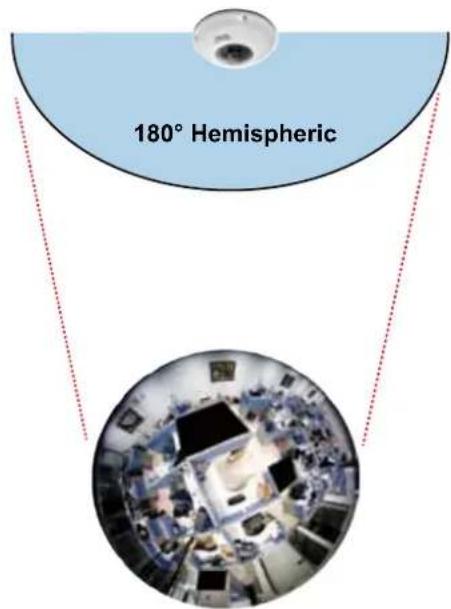
Fisheye Display Modes: below are conceptual drawings for different display modes.
10 (Single Original) Display mode:
An Original oval view covers the hemisphere taken by the fisheye lens.
10 View (Original View)
1R (Single Regional) Display mode:
A Regional view crops a portion of the hemisphere as a region of interest. You can zoom in or out or move the view area elsewhere from on the regional view.
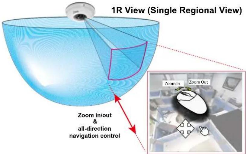
A Regional view is dewarped, by correcting images from the distorted oval view to a rectangular and visually proportional image.
1P (Single Panoramic) Display mode:
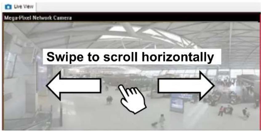
With image correction algorithms in firmware, the hemispheric image is transformed into a rectilinear stripe in the 1P display mode. Viewers can use the PTZ panel or simply use mouse control to quickly move through the 360^ panoramic view.
Note that the 1P view is apt for an overview, the Zoom in/out function does not apply in this mode.
1P (Panoramic) Mode Screen Control
2P (2 Panoramic) Display mode:
Two dewarped rectangular views are placed one on top of another each showing 180 degree of panoramic view. The 2P view looks like the upper view shows the front of hemisphere, and the lower view the rear half of the hemisphere.
2P (Panoramic) Mode Screen Control

103R (One Original & 3 Regional) Display mode:
Fisheye cameras also support the display of multiple regional views taken from within the same hemisphere, and they can be displayed with or without an Original view in its view cell.
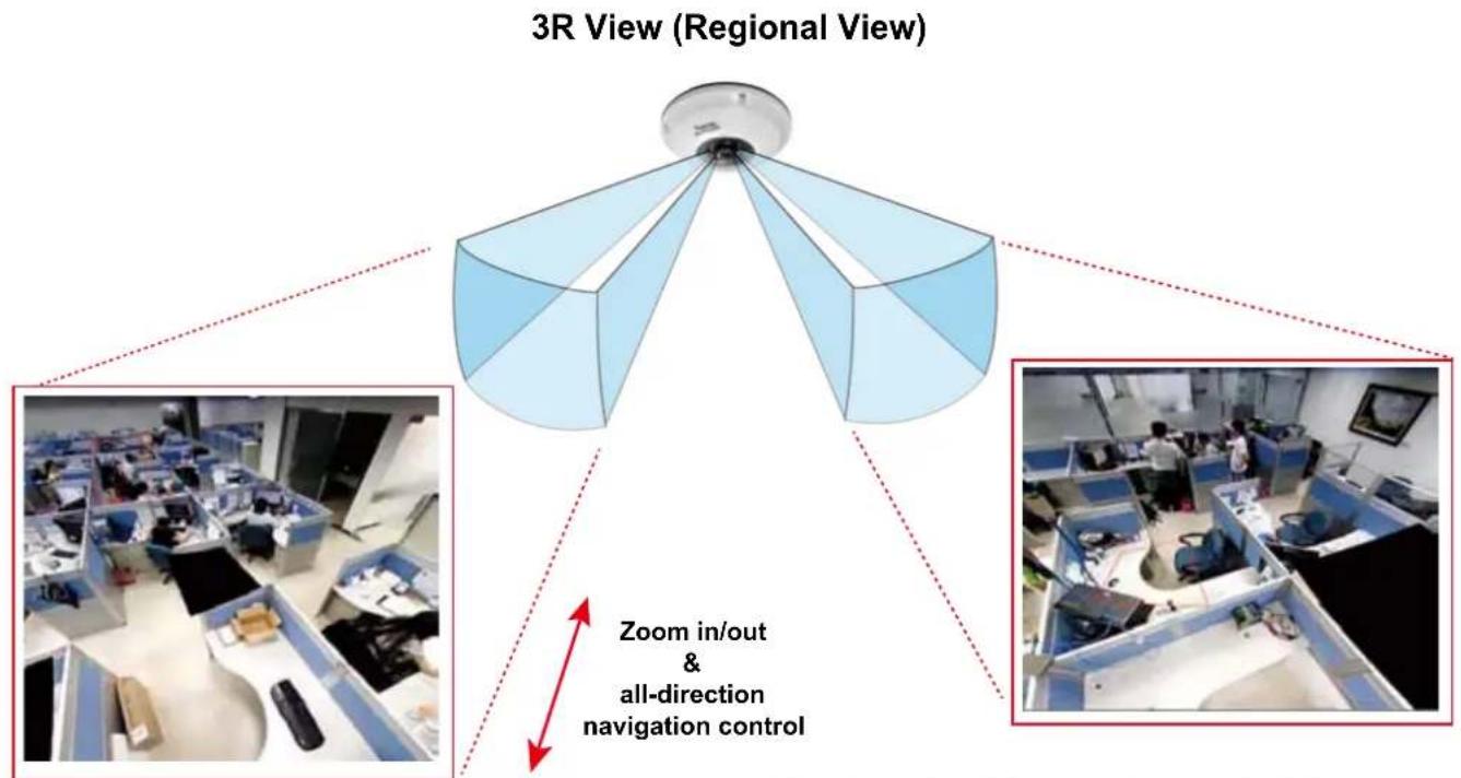
* Only two regional views are shown for simplicity reason
PTZ Mouse Control
The "Mount type" setting also determines the display modes available to your fisheye cameras. Please refer to fisheye camera's User Manual for more information.
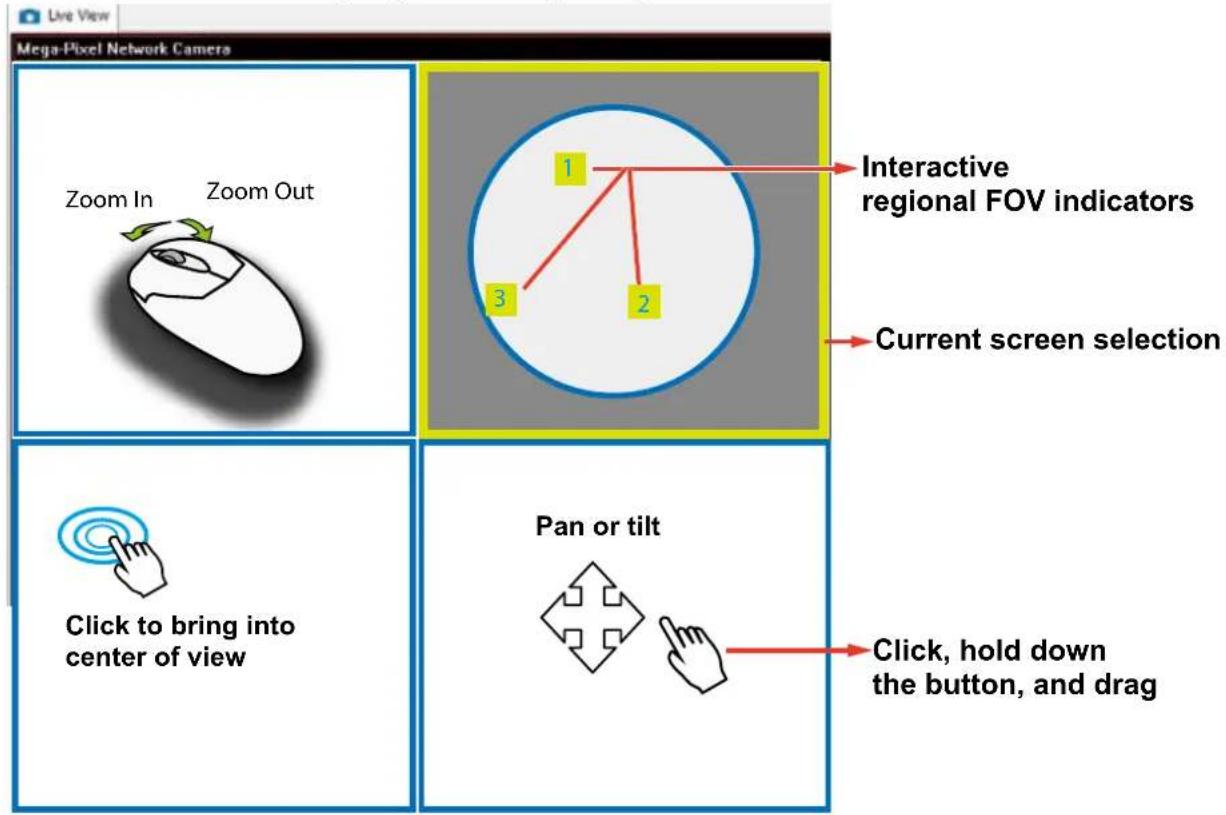
A highly versatile mouse control is implemented with fisheye cameras. The same control takes effect on a browser management session, on the LiveClient utility, and even on a video playback screen. See the drawing below for how it works.
You can click and hold down the left mouse button to quickly swipe through the field of view, change the view angle, or use the mouse wheel to zoom in/out on a region of interest. However, the PTZ mouse control is only available in the "R" (Regional) mode. In the Panoramic mode, you can only scroll horizontally across the 180° or 360° panoramic view.
1O3R (Original & Regional) Mode Screen Control

NOTE:
The various display modes require the support of D3D technologies by your display card. Most off-the-shelf display cards today support this feature.
The onscreen mouse control is very agile. Therefore, use the PTZ panel for more delicate moves in a field of view. Pan and Patrol moves are also supported if you have configured preset PTZ positions in the camera's firmware. Note that the Pan move takes place in the Panoramic and Regional views, while the Patrol function through preset positions applies only in the Regional views.
Below are the conceptual drawings for other display modes:
1P3R (One Panoramic & 3 Regional) Display mode:
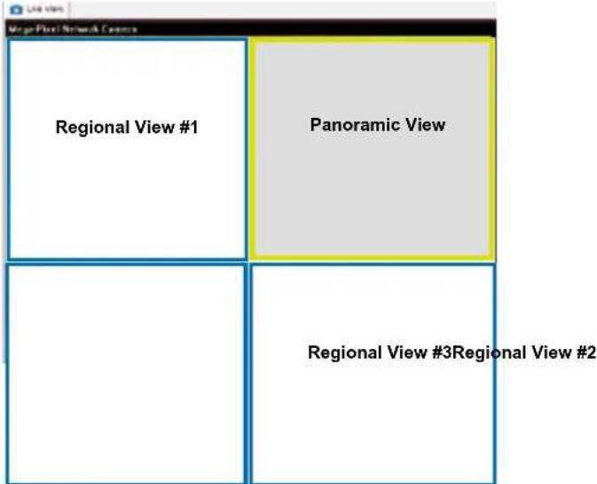
4R (Quad Regional) Display mode:
4RPro (4 Regional Proactive) Display mode:
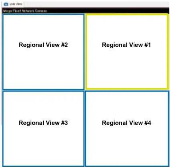
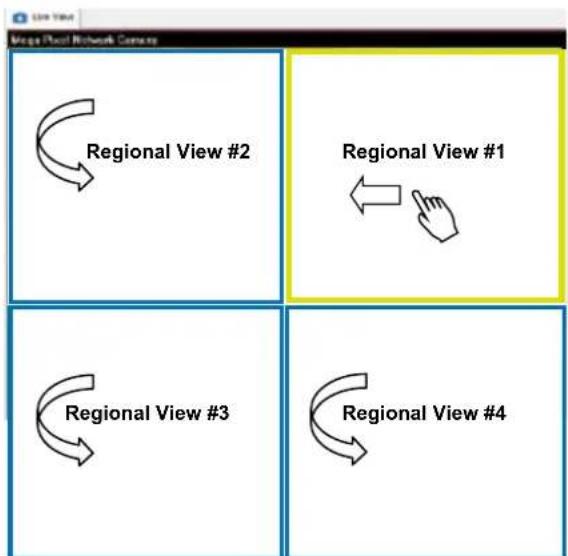
flowchart
graph TD
    A["Regional View #2"] --> B["Regional View #1"]
    C["Regional View #3"] --> D["Regional View #4"]
    E["Regional View #1"] --> F["Regional View #2"]
    G["Regional View #3"] --> H["Regional View #4"]
108R (One Original & 8 Regional) Display mode:
| Mega-Pixel Network Camera 2011/09/01 05:41:35 | ||
| Regional View #3 | Regional View #1Regional View #2 | |
| Regional View #4 Regional VOriginalView | ||
| Regional View #6Regional View #5 Regional View #7 | ||

NOTE:
For Fisheye video playback and recording concerns, refer to page 132 and page 168.
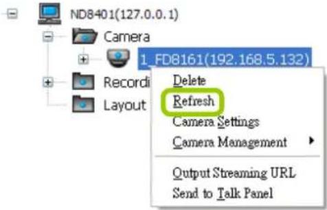
Refresh
Right-click the device, then click Refresh, the camera information will be refreshed from the server.
Streaming Server
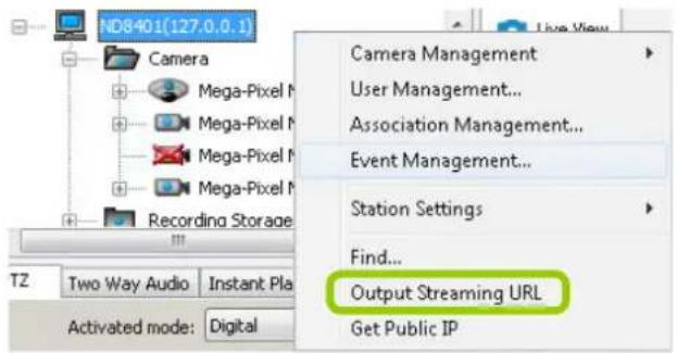
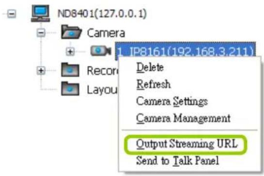
Right-click the station or the device and click Output Streaming URL. A .txt file with streaming URL will pop up. Then you can use this URL to link to the live streaming through QuickTime Player.
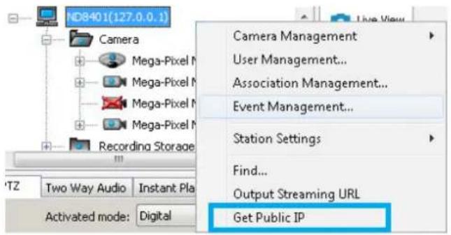
Get Public IP
If your access to Internet is via PPPoE, this function will display the public IP provided by your service provider. If your access to Internet is via a router, please consult your network administrator or consult your ISP for a valid public IP.
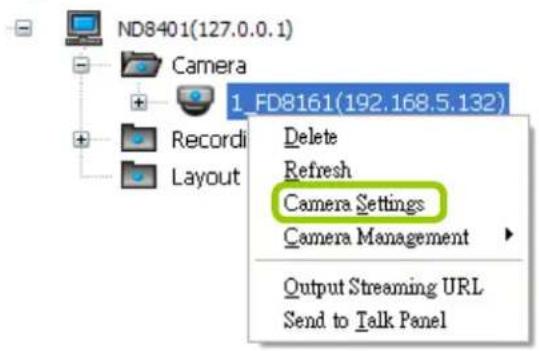
Camera Settings
Right-click the device, then click Camera Settings to open a brower's session to the camera.
Remove Live Video from the Video Monitoring Window
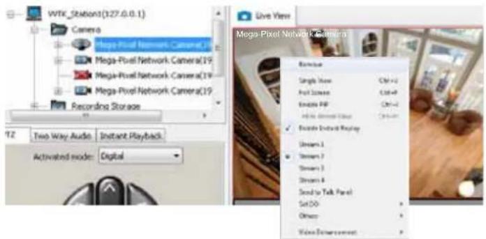
There are two ways to remove a live video from the video cell:
Method 1. Right-click the video cell and select Remove.
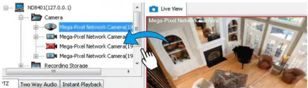
Method 2. Drag-and-drop the live view from the video cell to the hierarchical management tree window.

NOTE:
If you want to remove all live videos from the video cells, please click on the menu bar.

How to Change the VAST LiveClient Layout
Changing the Layout of the Live Video Monitoring Window
The NVR's LiveClient supports up to 16 simultaneous video viewing on a single monitor and allows you to change the layout of the live video monitoring window based on the number of inserted devices.
Switch Video Channels
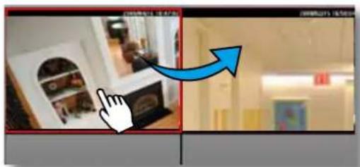
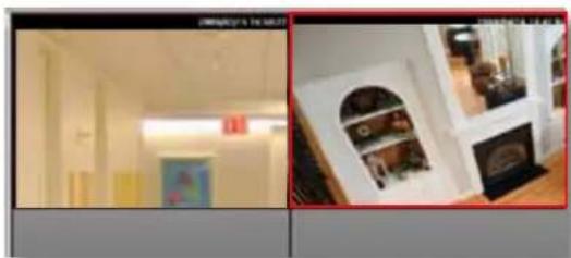
To move a video channel to another empty video cell, drag-and-drop the view to the target video cell.
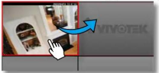
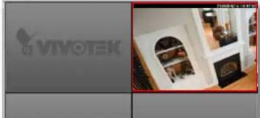
To switch two different channels, drag-and-drop one view to the other, then the two different channels will be switched to the opposite.
natural_image
Interior view of a modern room with ceiling lights and a wall-mounted appliance (no visible text or symbols)Configure Layout Mode
Click the Layout button ☐ on the quick access bar. Select a desired layout mode, and the layout window will change accordingly. Below we illustrate 6 types of layout modes and the corresponding page numbers:

| Layout mode | Description | Video page |
| 1 x 1 | 32 | |
| 2 x 2 | 8 | |
| 1 + 5 | 4 | |
| 3 x 3 | 3 | |
| 1 + 12 | 2 | |
| 4 x 4 | 2 |
Some layout modes (1 x 1, 2 x 2, 1 + 5, 3 x 3, 1 + 12, 4 x 4) will spread the view cells of video channels over several pages.
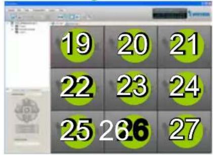
For example, under the 3 x 3 layout mode, you can switch among the pages by clicking and on the quick access bar. To arrange the content of each page, manually drag-and-drop cameras from the hierarchical device tree to the video cells on each page.
Page 1 Page 2
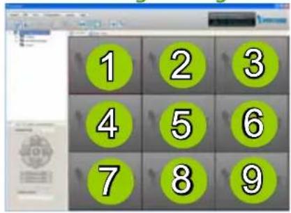
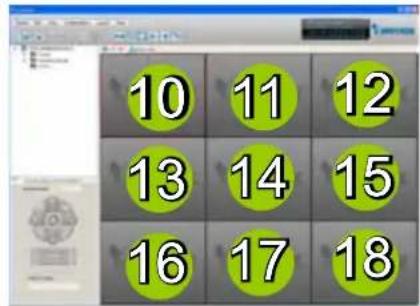
Page 3
Rotating Video Pages

For layout modes that contain more than one page, the LiveClient offers the rotating function for displaying all video pages in turn.
■ To enable this function, click 📋 on the Quick Access Bar, which will become 🔒 Stop Rotating, and the video pages will start to rotate so that the user does not have to click → to move to the next page.
■ To disable this function, click Stop Rotating, which will become on the Quick Access Bar.
You can also click Layout > Start to Rotate/Stop Rotating to enable/disable this function.
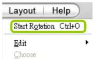
The default rotating time interval is 6 seconds. If you want to edit rotation settings, please refer to Rotation Settings on page 135.
Edit Layout
Please follow the steps below to save a layout:
a. Arrange a layout mode and drag devices to their desired video cells.
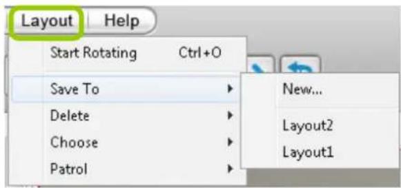
b. Click Layout > Edit > Save to > New on the menu bar. A Layout Name dialog box will pop up.
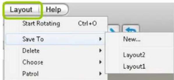
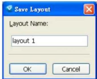
c. Enter a name for the layout, then click OK to enable the setting.
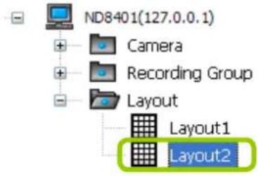
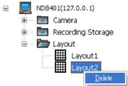
d. Back to the monitoring window, the new layout will appear under the device tree as shown below. You can save up to 10 layouts.
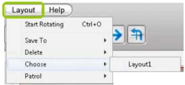
e. To change to another layout, double-click the layout options on the hierarchical management tree, or click Layout > Choose on the menu bar to select a desired layout.
If you want to edit an existing layout, arrange a layout mode and drag devices to the desired video cells, then click Layout > Edit > Save to > New to save as a new layout or an existing layout to replace with the new one.
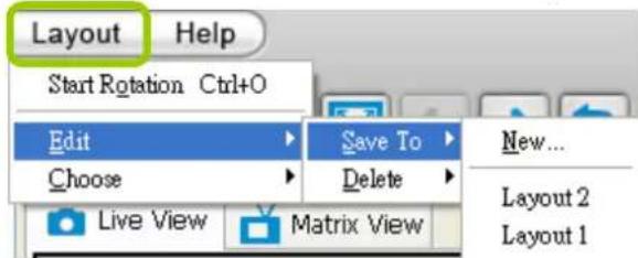
■ If you want to delete an existing layout, right-click the layout item on the hierarchical management tree or click Layout > Edit > Delete on the menu bar to delete it.

NOTE:
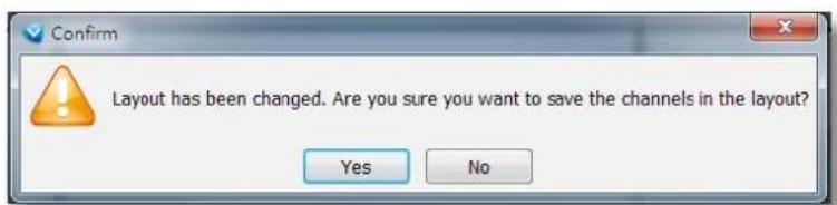
Whenever you close the LiveClient or Playback programs and changes in screen layout have been made, you will be prompted to save your current configuration.
Maximize the Live Video Monitoring Window
■ Single View: to maximize a video cell to the entire live video window
Double-click the video cell, or right-click the video cell and select Single View. The focused video will occupy the entire playback window as shown below.
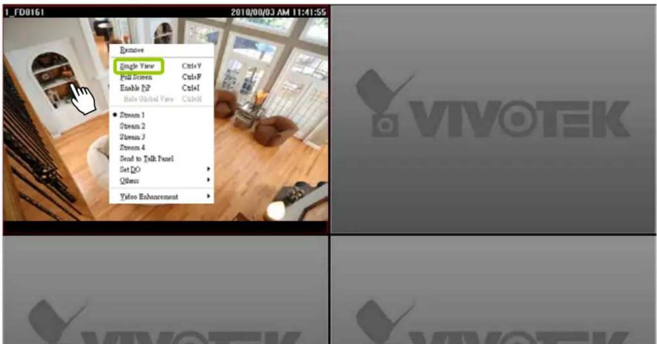
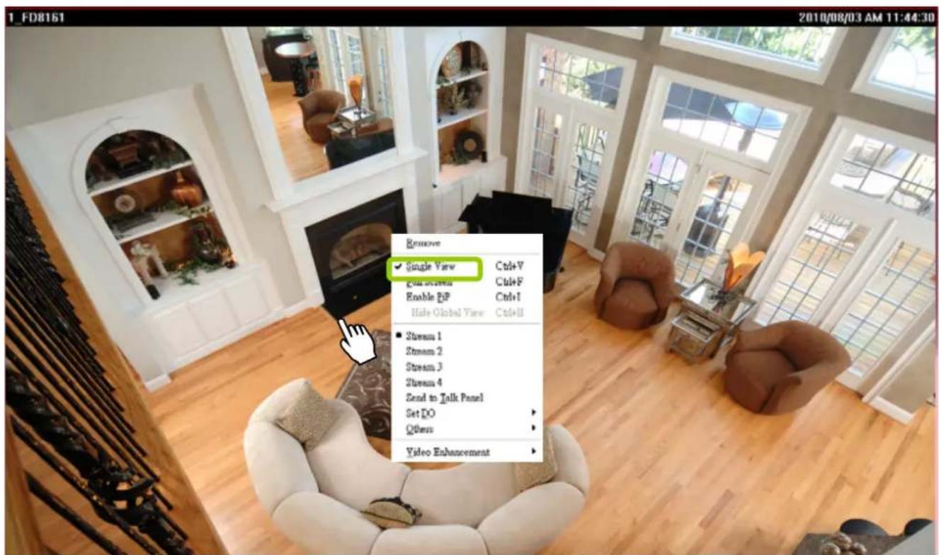
To restore to the original layout, double-click the video cell or right-click the video cell and uncheck Single View.
■ Full Screen: Maximize the live video monitoring window to the entire screen
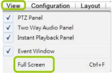
Click Full Screen 📧 on the quick access bar or right-click the video cell and select Full Screen. In addition, you can also click View > Full Screen on the menu bar to maximize the live video monitoring window.
To restore to the original layout, you can right-click a video cell and uncheck Full Screen or click the Esc button on the keyboard to exit full screen mode.
How to Manage Stations
A standard VAST Server allows you to construct a hierarchical management system by adding more sub-stations to the root station. The NVR system can be included into a hierarchy managed by a dominating VAST server. The NVR system itself can not manage other sub-stations.
Relay Settings
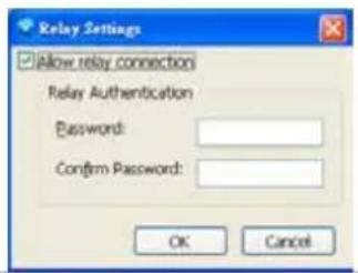
Before adding a sub-station, please follow the instruction below to enable the sub-station's Relay Settings first.
a. Login to the sub-station.
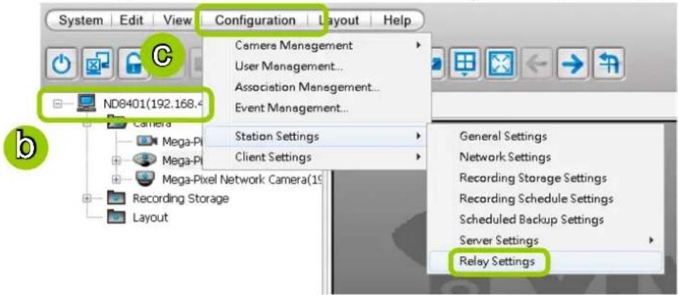
b. Select the station from the hierarchical management tree.
c. Click Configuration > Station Settings > Relay Settings on the menu bar (or right-click the station on the hierarchical management tree and select Station Settings > Relay Settings).

d. The Relay Settings window will pop up. Check Allow Relay Connection and enter a Password. Then click OK to enable the settings.
How to Manage User Accounts
VAST on NVR allows users to apply multiple user accounts to a station with five levels of user roles: Administrator > Power User > User > Operator > Guest. Each role has different permissions listed as shown below. Moreover, Administrators have the highest privileges, while Power Users can only add/edit users as Power Users, Users, Operators, and Guests.
The Default User Roles and Permissions of User Accounts
| Functions \ User Roles | Administrator | Power | User | Operator | Guest Description | |
| User Management | √ | √ | √ | Manage user accounts | ||
| Camera Management | √ | √ | Insert and configure the camera settings | |||
| Association Management | √ | √ | √ | Access and modify the association settings | ||
| Access Event Management | √ | √ | √ | Access event management | ||
| Modify Event Management | √ | √ | √ | Modify event management | ||
| General Station Settings | √ | √ | Modify general station settings | |||
| Station Network Settings | √ | √ | Modify network settings | |||
| Access Recording Storage/Recording Schedule Settings | √ | √ | √ | √ | Access the Storage Group and recording schedule | |
| Modify Recording Storage/Recording Schedule Settings | √ | √ | √ | Configure the Storage Group and recording schedule | ||
| Manually Record | √ | √ | √ | √ | Enable the recording function manually | |
| Scheduled Backup Settings | √ | √ | √ | Configure backup schedule | ||
| Access Server Settings | √ | √ | √ | Access server settings | ||
| Modify Server Settings | √ | √ | √ | Modify server settings | ||
| Relay Management | √ | √ | Allow user to manage station relaying settings | |||
| Client Settings | √ | √ | √ | √ | Configure the client settings: snapshot, AVI, etc. | |
| Video Enhancement Settings | √ | √ | √ | Allow user to edit profile for video enhancement and assign profile to camera in LiveClient |
| Privileges \ User Roles Administrator Power User User Operator Guest Description | |||||
| Modify Directories | √ | √ | √ | Add, remove and rename directories | |
| Delete Camera | √ | √ | Delete camera from the station | ||
| PTZ Control | √ | √ | √ | √ | PTZ control for PTZ cameras and speed domes in LiveClient |
| Device Control | √ | √ | √ | √ | Control the digital output or white light/IR illuminators of the cameras |
| Talk Control | √ | √ | √ | √ | Two way audio function for the cameras |
| Access Camera Configuration | √ | √ | √ | Access the camera settings | |
| Modify E-map | √ | √ | √ | √ | Allow user to modify the E-map |
| Event Search | √ | √ | √ | √ | Use built-in search engine to search specific events |
| Log Viewer | √ | √ | √ | √ | Use built-in search engine to search the log |
| Backup | √ | √ | √ | √ | Back up database manually |
| Record/Export Media | √ | √ | √ | √ | Record live stream or export playback stream to local files |
| Playback Authority | √ | √ | Allow user to access Playback | ||
Manage a User Account
Add a New User Account
a. Select the station from the hierarchical management tree.
b. Click Configuration > User Management on the menu bar (or right-click the station, then select User Management).
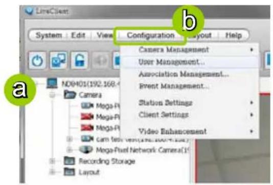
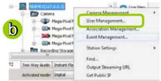
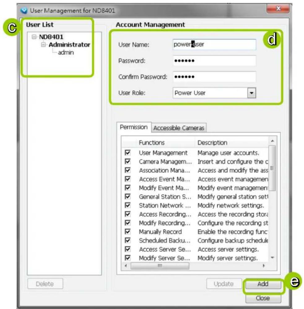
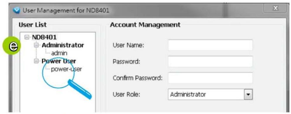
c. The User Management window will pop up. The user accounts under the station will be displayed under the left User List tree.
d. Enter the User Name, Password, and specify the User Role of this user.
e. Click Add to add the user account to the station. It will be displayed under the User List.
Permission of the User Account
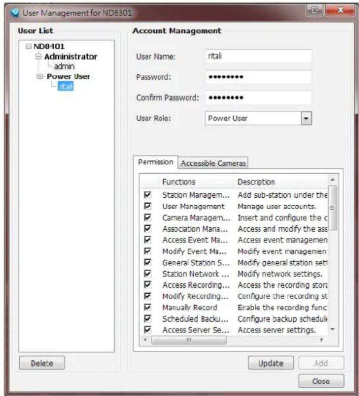
Administrator is granted with all access privileges, while other user roles' permission is limited. If you want to modify the permission, please login as the Administrator to configure the settings.
f. Select a User account from the User List tree.
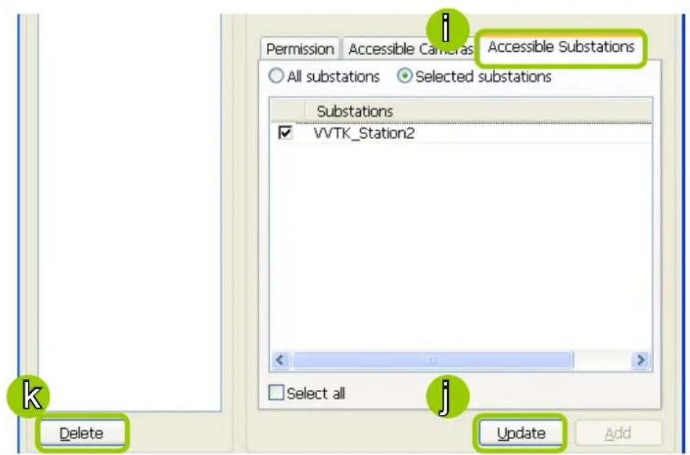
g. If you want to set the limit of the permission of the user, click Permission tab to check or uncheck the items.
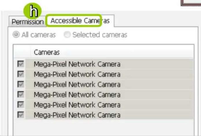
h. If you want to limit the devices accessible by the user, click Accessible Cameras tab to select the desired devices.

NOTE:
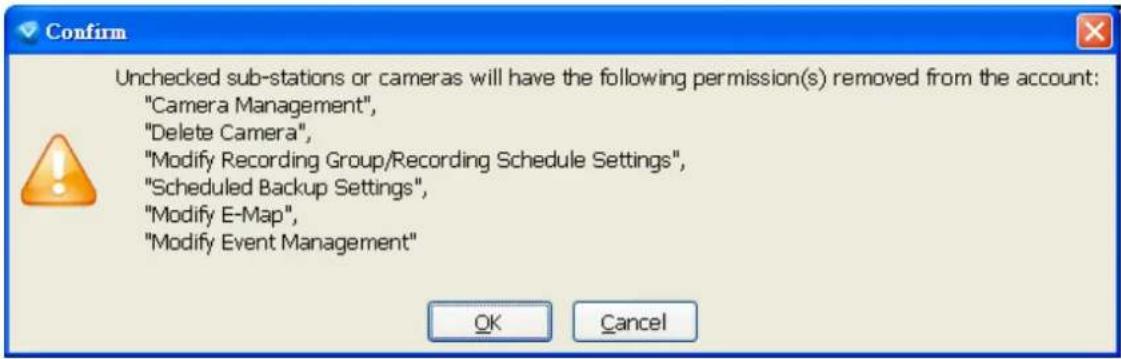
If you want to remove access permission mentioned above from the account, the user will not be able to operate some functions listed in the following warning dialog.
j. When completed, click Update to enable the new settings.
Delete the User Account
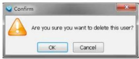
k. Click Delete, a delete user dialog will pop up. Click OK to delete the user account.

NOTE:
If the Administrator modifies or deletes the User Account, that modified user might be kicked off from the station.
How to Set up Association Management
The LiveClient supports association management which allows the user to configure relative event trigger notifications of the connected network devices. (E.g., DI/DO status on the management tree, motion detection windows appearing in the video cell, or the event list in the event window)
Association Management
Please follow the steps below to configure association settings:
a. Select the station from the hierarchical management tree.
b. Click Configuration > Association Management on the menu bar (or right-click the station and select Association Management).
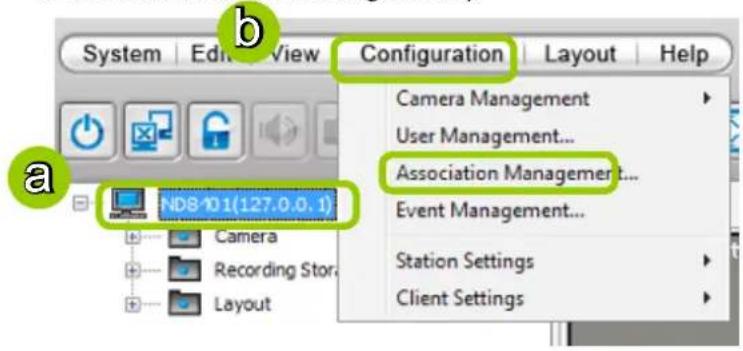
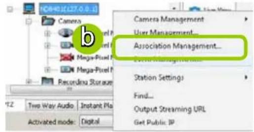
c. The Association Management window will pop up. Check or uncheck the items and click Save to enable the settings. The items you've selected will also be displayed under the hierarchical management tree.
For example:
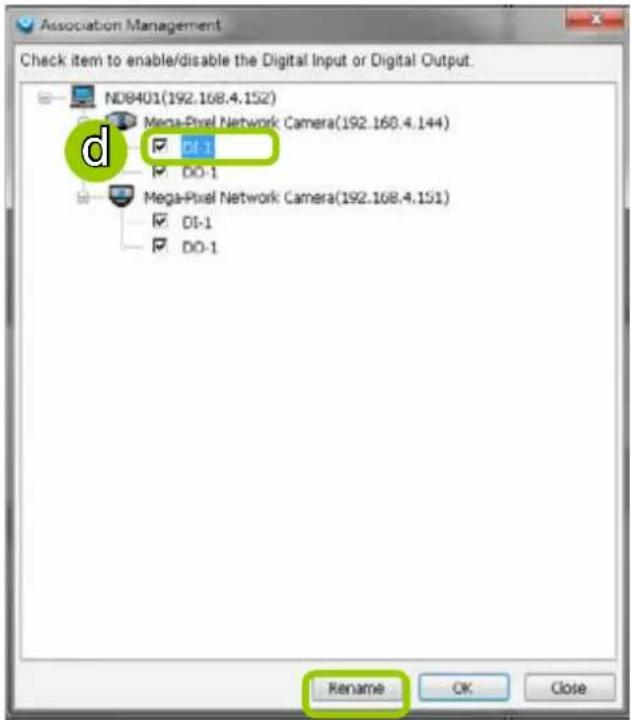
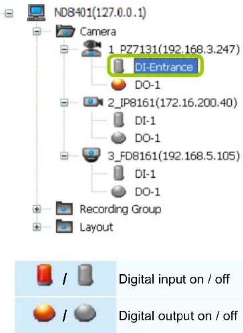
d. If you want to rename the DI device, select the DI item and click the Rename button. It will be very convenient for you to recognize the target DI device.

NOTE:
■ To manually enable DI/DO settings, please right-click the video cell and select Set DO to enable (Trigger) or disable (Normal) the digital output of the linked device.
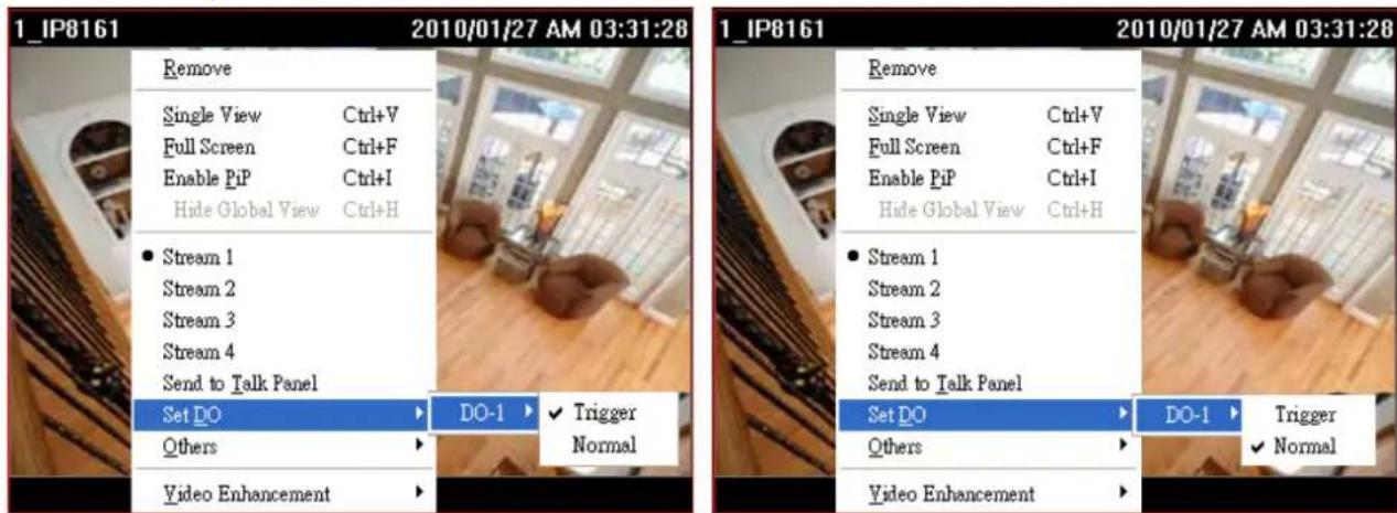
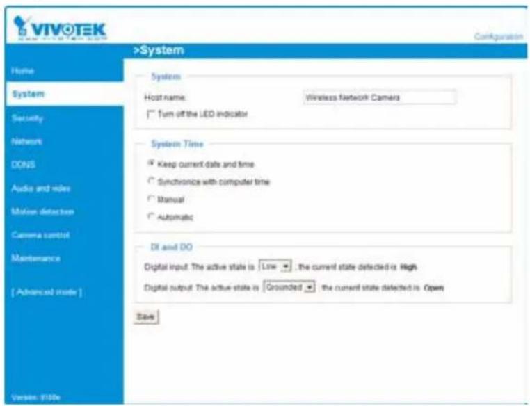
■ Before you configure the DI/DO Settings for VAST, please enable DI/DO configurations on your network device and set up the camera correctly on the configuration page. You can right-click the device and click Camera Settings to open the configuration page.
![ND8401(127.0.0.1) Camera 1_FD8161(192.168.5.132) Recordi Delete Layout Refresh Camera Settings Camera Management Output Streaming URL Send to Talk Panel LiveClient Browser VIVOTEK Configuration >System Home System Host name: Network Camera □ Turn off the LED indicator System Time ● Keep current date and time ○ Sync with computer time: ○ Manual: ○ Automatic: Bl and 3D Digital input: The active state is Low ▼; the current state detected is High Digital output: The active state is Grounded ▼; the current state detected is Open [ Advanced mode ] Save](/content/2026/06/1279498/images/57e890afdbe84f5b40cbb07688d7097f09ffe61873e1f445c2ce57551a9d2374.jpg)
How to Set up Event Management
The NVR's LiveClient supports event management which allows the server to respond to particular situations (events). LiveClient can correspond with cameras' input and respond with associated reactions, such as sending notifications, telling cameras to move to preset locations, etc.
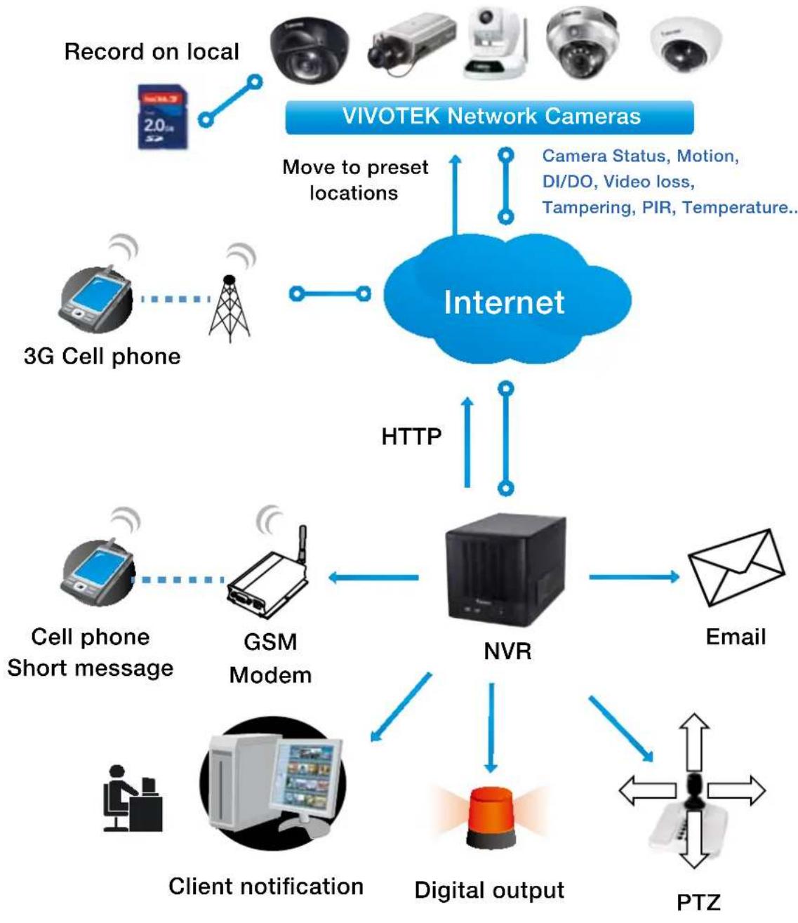
flowchart
graph TD
    A["VIVOTEK Network Cameras"] -->|Move to preset locations| B["Internet"]
    C["Record on local"] -->|2.0Hz signal| B
    D["3G Cell phone"] --> E["3G Phone"]
    E --> F["3G Phone"]
    G["Cell phone Short message"] --> H["GSM Modem"]
    I["Client notification"] --> J["Digital output"]
    K["PTZ"] --> L["PTZ"]
    M["Email"] --> N["NVR"]
    B <-->|HTTP| N
    N <-->|HTTP| B
    style B fill:#99ccff,stroke:#333
    style N fill:#cccccc,stroke:#333
Event Management
Please follow the steps below to configure event management:
a. Select the station from the hierarchical management tree.
b. Click Configuration > Event Management on the menu bar (or right-click the station and select Event Management).
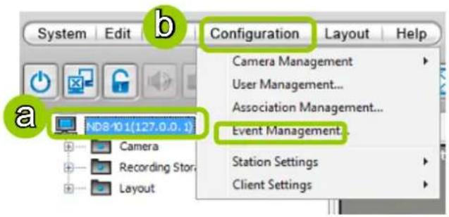
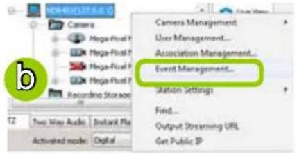
c. The Event Management window will pop up. Click New to set up a new event. When you finish the general settings, click Next to set up trigger source settings.
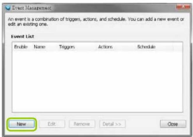
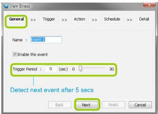
d. Click Add to select the trigger source by Device or Trigger Type.
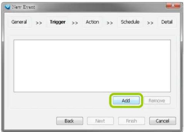
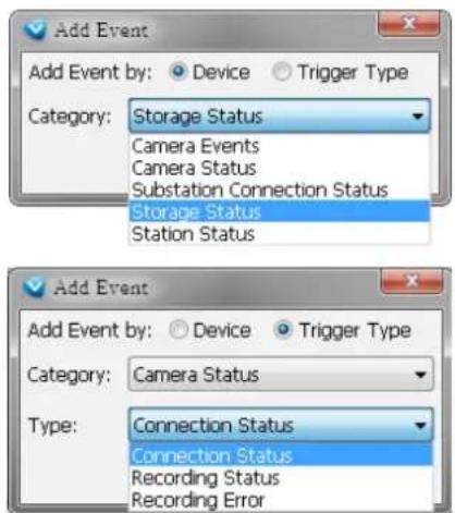
e. The Device List window will prompt. Select one or more devices and set the Notification Type. Depending on the trigger source, the Notification Type will be different. Then click OK to close the window.
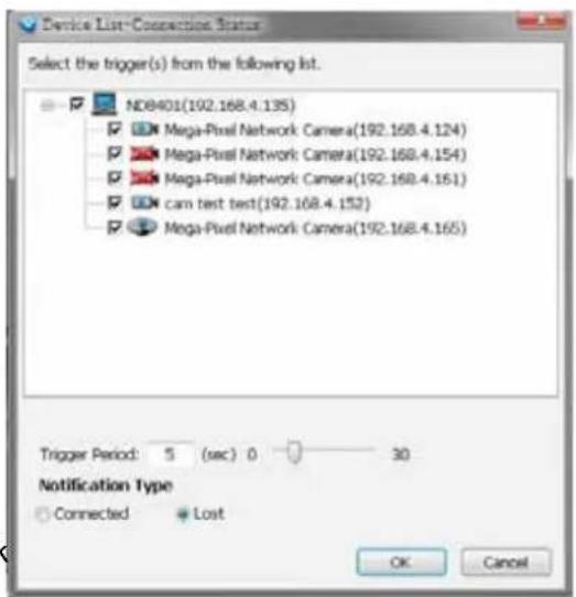
f. The trigger source(s) will be listed on the window as shown below. If you want to add more Trigger sources, click Add and repeat steps d.and e. Then click Next to assign action(s) to the trigger source(s).
g. Click Add to open the Action Settings window.
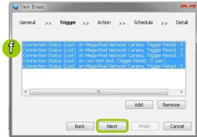
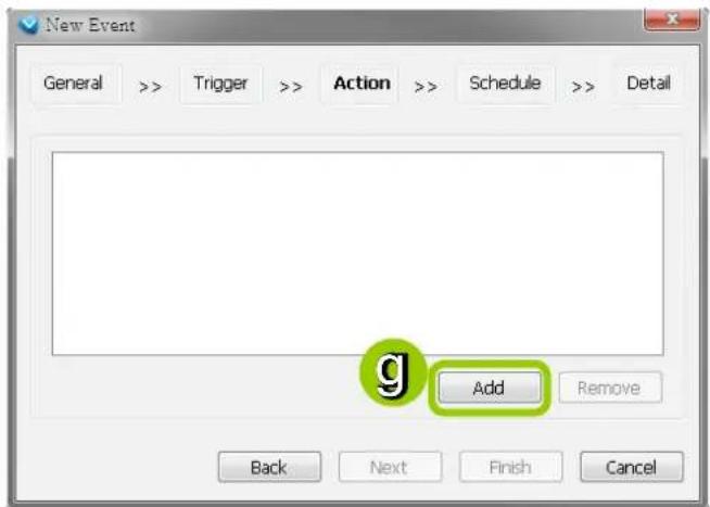
There are several options with the Action Settings.
■ Email: The sever will send a notification via e-mail when a trigger is activated.
h. To enable this function, please set up the SMTP server first. Click SMTP Setting to open the window and refer to page 112 for detailed information.
i. Enter the related information. You can modify the mail content in the blank. If you want to modify the content, click Insert Macro to select the parameter. When completed, click OK on the bottom to enable the setting.
![Action Email From : To : Cc: At $(EventTime), event type [$(TriggerType)] occurred on Content: $(DeviceName) Insert Macro Device Name Trigger Type Event Time Storage Path Start to record on Move to preset location Set DO GSM short message HTTP Client Notification OK Cancel](/content/2026/06/1279498/images/d22d0aa460a342bcc67fa50bb1e2a6d3ad22f5b8bc549fdef47d5c74821e97b5.jpg)
■ Start to record on: The sever will start to record video from selected camera(s) when an event is triggered.
j. Click Add Camera to select the target camera(s).
k. The selected camera(s) will be listed on the left window below. When completed, click OK at the bottom to enable the setting.
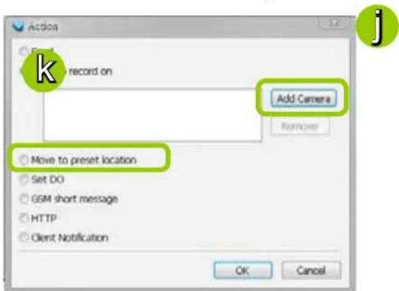
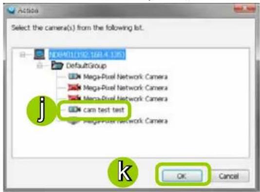
■ Move to preset location: The target camera(s) will move the shooting area to the preset location(s) when an event is triggered.
I. To enable this function, please set preset locations on the camera configuration page first.
m. Click Add Location to select preset location(s).
n. The selected preset location(s) will be listed on the left window below. When completed, click OK at the bottom to enable the setting.
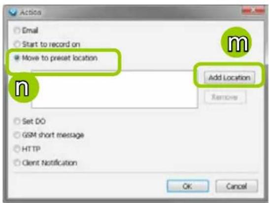
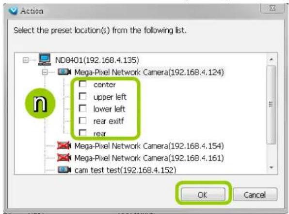
- Set DO: Select this option to turn on external digital output device(s) when an event is triggered. For more information about how to set DI/DO settings on the target camera, please refer to page 71.
o. Click Add DO to select DO deceive(s) and select a DO status (Normal or Trigger).
p. The selected DO device(s) will be listed on the left window below. When completed, click OK to enable the setting.
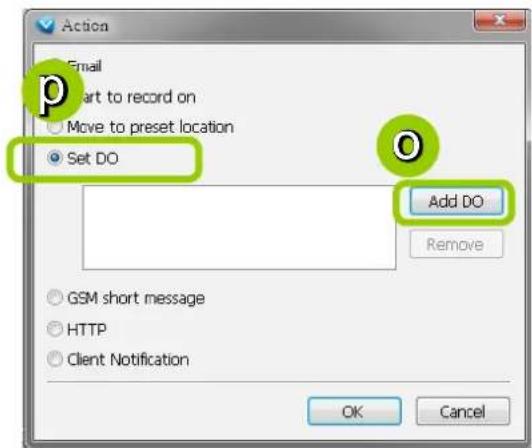
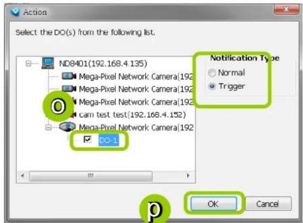
■ GSM Short Message: The sever will send a short message to a GSM cell phone when an event is triggered. A GSM modem is necessary.
q. Please enter the Phone Number and open GSM Settings window to set related information if necessary. When completed, click OK to enable the setting.
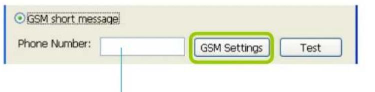
Please enter the country code if you use overseas call.
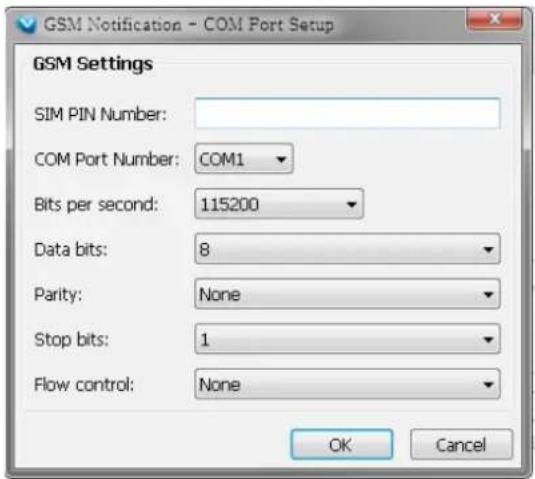
- HTTP: This function allows user to send a CGI command to the linked network camera, such as pan/tilt/zoom function or enable DO devices.
r. You can click Insert Macro to select the parameter. Please enter authentication information if necessary. For example: http://192.168.3.66/cgi-bin/admin/setparam.cgi?system_hostname=\(EventTime) \(CameraName)
If you want to use special characters such as - _ . + ! * ' ( ) , # % + \ , @ : ; / ? = \&$ , please refer to the following table to transfer the Code (Hex).
For example: http://192.168.3.66/cgi-bin/admin/setparam.cgi?system_hostname=123&456
--> http://192.168.3.66/cgi-bin/admin/setparam.cgi?system_hostname=123%26456
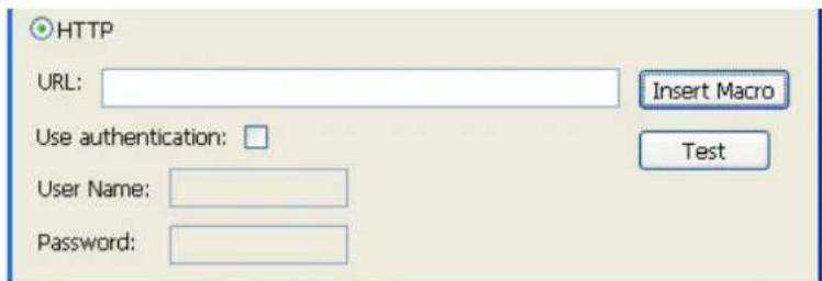
| Character Code (Hex) | |
| ! | 21 |
| # | 23 |
| $ | 24 |
| % | 25 |
| & 26 | |
| ' 27 | |
| ( | 28 |
| ) | 29 |
| * | 2A |
| + | 2B |
| Character Code (Hex) | |
| , | 2C |
| - | 2D |
| . | 2E |
| / | 2F |
| : | 3A |
| ; | 3B |
| = | 3D |
| ? | 3F |
| @ | 40 |
| - | 5F |
| ~ | 7E |
■ Client Notification: This function allows a notification video cell to prompt when an event is triggered. You can select the size of the video cell, and select how long the view cell will stay on top of the screen.
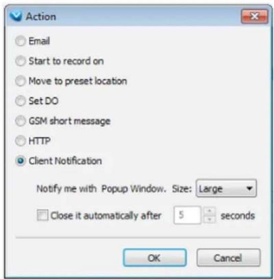
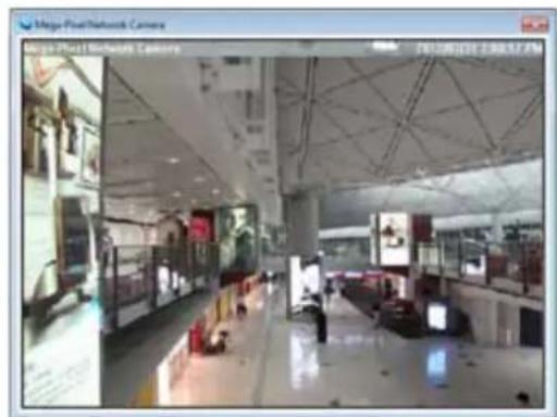
s. The action(s) will be listed in the window as shown below.
Then click Next to set up schedule(s) to the action(s).
For more information about Schedule Settings, please refer to Recording Schedule Settings on page 89. You can assign more than one time frame during twhich an action will take effect.
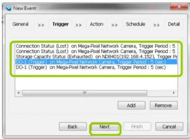
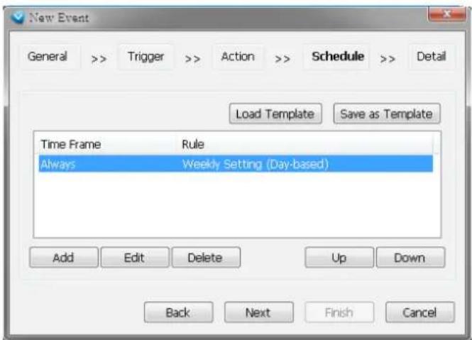
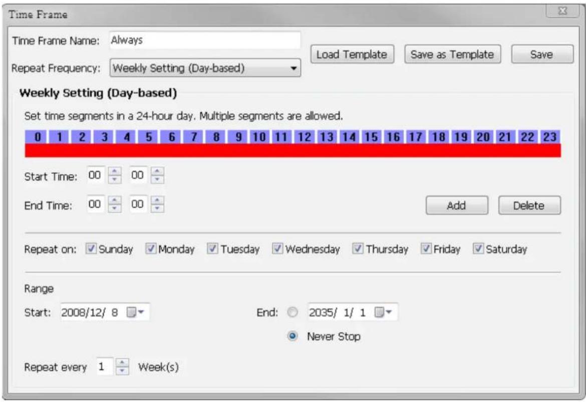
t. When you finish schedule settings, click Next to review the detailed information of the new event settings.
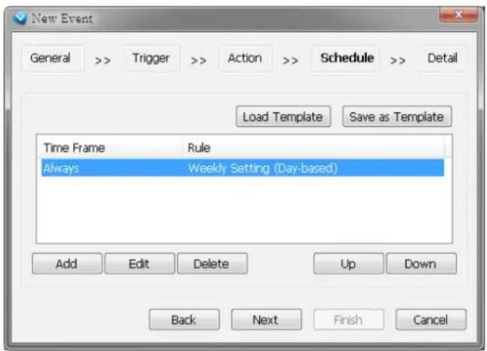
u. Following is the detailed information of the new event setting. You can click Back to modify the event setting or click Finish to close the window.
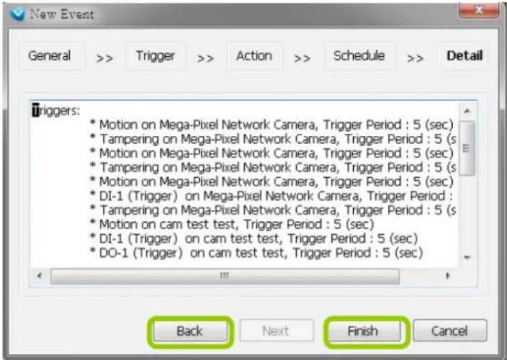
v. Following is an example of an enabled event. You can click New to set up more events or click Close to exit the window.
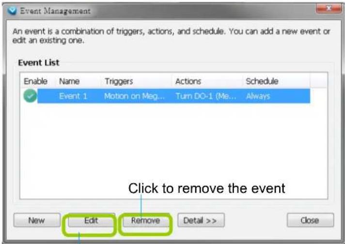
Click to disable or modify the selected event
How to Configure the Station General Settings
Select the target station from the hierarchical management tree, then click Configuration > Station Settings > General Settings on the menu bar (or right-click the station on the hierarchical management tree and select Station Settings > General Settings). The Station General Settings window will pop up.
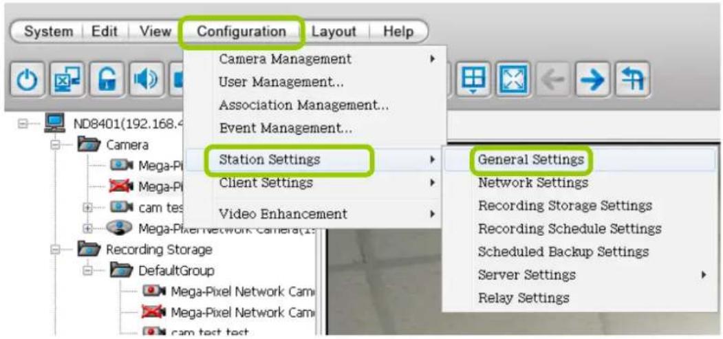
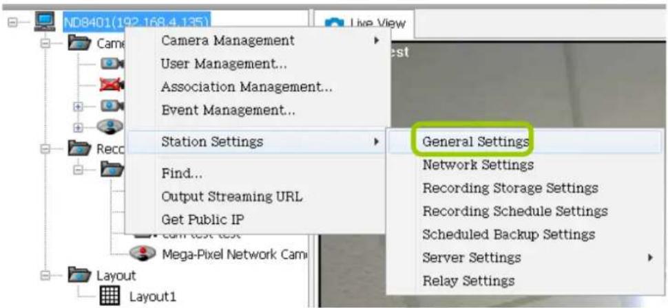
Server Settings
In this section, you can modify the name of your NVR Station.
Log Settings
In this section, you can set up Log Settings for the station.
The VAST server allows users to search for the recorded log through VAST Playback. For more information, please refer to How to Search Logs on page 179.
■ Log level: Select High (only record high-level logs), Normal (record high-level and normal-level logs), Low (record all logs). For detailed information about log levels, please refer to page 180.
■ Reserve Time: Enter the extension of time that you want to reserve the log record. The maximum value is 365 days.
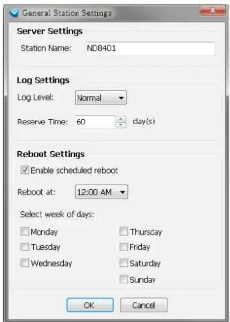
Reboot Settings
You can schedule a system reboot every day at a specific time in a day or in days within a week. Select the checkbox and select a time from the pull-down list.
Click OK when the configuration is done.
How to Configure Station Network Settings
Select the target station from the hierarchical management tree, then click Configuration > Station Settings > Network Settings on the menu bar (or right-click the station on the hierarchical management tree and select Station Settings > Network Settings). The Network Settings window will pop up.
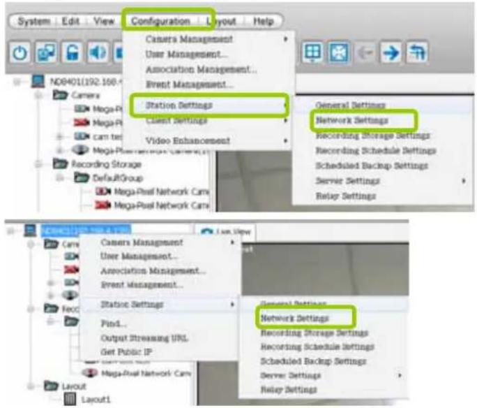
Port Settings
■ Server port: The default server port is set to 3454. If you change the server port, please enter the new value while logging the LiveClient next time.
■ RTSP port: The RTSP (Real-Time Streaming Protocol) controls the delivery of streaming media. By default, the port number is set to 554.
UPnP Settings
■ Enable UPnP port forwarding: For client to access the VAST Server from the Internet, select this option to allow the server to open ports on the router automatically so the video streams can be sent out from a LAN. To utilize of this feature, make sure that your router supports UPnP ^TM and it is activated.
■ Enable UPnP presentation: If you select this option, shortcuts to VAST Server will be listed in My Network Places.
Proxy Settings
In this section, you can enable, modify, or cancel Proxy Settings for VAST Server if your network devices are set up under a proxy.
Web Access Settings
User can access LiveClient and Playback via Internet web browser (http://IP address:3454).
For local host --> http://127.0.0.1:3454.
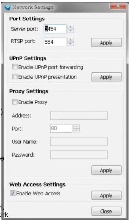
How to Edit Recording Stoage
By default, all devices (cameras) are assigned to the default recording storage. You can manually remove a device from the default recording storage. However, only those devices which belong to a recording storage can produce recorded media files.
Another purpose of setting the recording storage is that you can divide all the managed devices into several recording storages, and for each storage group, you can assign several hard-disks or disk volumes (with its unique recording paths) to store media data. The live media data will be stored in the first assigned hard-disk initially, and when the available space of the first hard disk reaches the preset threshold for a reserved space, the media data will be stored in the following disk and so on. If the available space of the last disk reaches the threshold of reserved space, the recorded files in the first disk will be overwritten with the new media data. This procedure is called "Cyclic Recording".
Recording Storage Settings
Please follow the steps below to set up recording storages for a station:
a. Select the target station from the hierarchical management tree.
b. Click Configuration > Station Settings > Recording Storage Settings on the menu bar (or right-click the station on the hierarchical management tree and select Station Settings > Recording Storage Settings). You can also right-click DefaultGroup under the station and click Recording Storage Settings since all devices are assigned to the Default Storage Group by default settings.
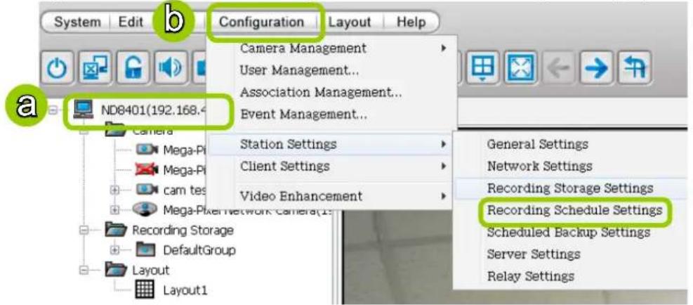
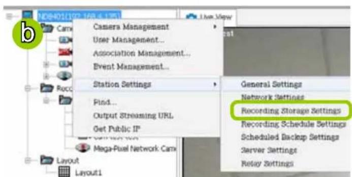
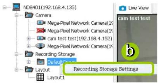
c. The Recording Storage Settings window will pop up.
Default Storage Group Settings
The following example shows the default storage group settings. You can click ☑ Rename to modify the group name or click ✗ Delete to remove the default settings.
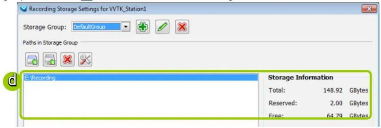
d. The default recording path is E:\Recording. The total space and free space of the disk is shown on the right for reference. On the NVR system, the boot disk (IDE flash) is segregated into two logical partitions as C: and D: drives. C: and D: are not used for storing user data. The E: partition, the disk volume you created from the SATA drives is used for recording video data.
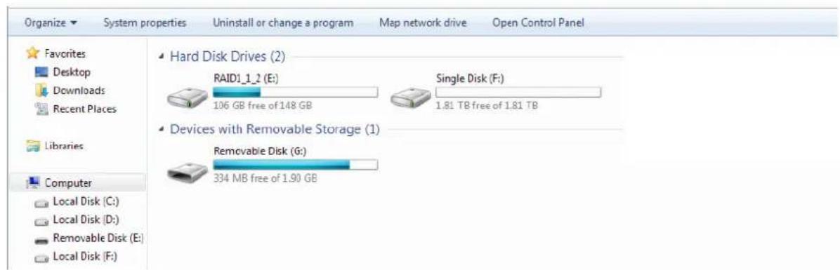
e. Add Local Path: Click to add another recording path on your local computer. A Select Path dialog will pop up as shown below. When all settings are complete, click OK to enable the settings, or click Cancel to discard the settings.
f. Add Network Path: Click 📋 to add a network storage for recorded data. Please refer to page 111 for detailed information about how to add a new network storage server. Then double-click the Path to assign a specific folder as a new recording path.
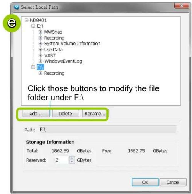
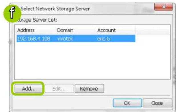
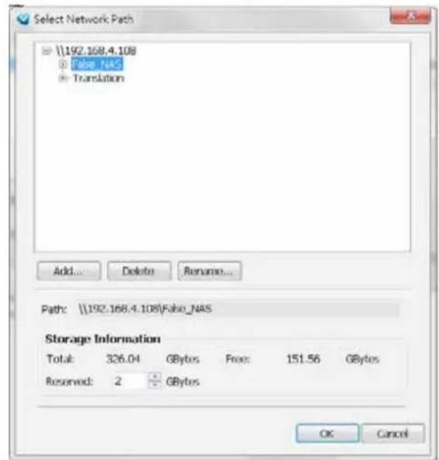
g. To modify the settings of a path, select the path from the list, then click ☒ Change settings to modify.
h. To delete a path, select the path from the list and click ✗ Delete path. A warning dialog box will pop
up as shown below.

i. By default, all devices are assigned to the Default Storage Group in the window to the right. You can select device(s) from the list and click <- to delete device(s) (or right-click the device under DefaultGroup tree to delete it). Note that a Delete Camera dialog box will pop up. Click Yes to delete the device along with the recorded data; click No to delete the device but retain the recorded data; click Cancel to cancel the delete action. Please note that only those designated devices can record videos.
j. Click >> to add devices to the DefaultGroup.
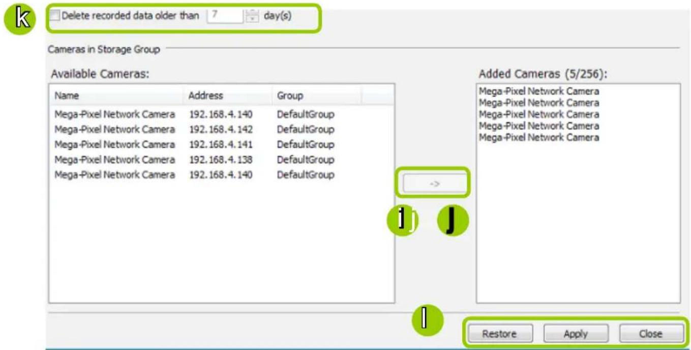
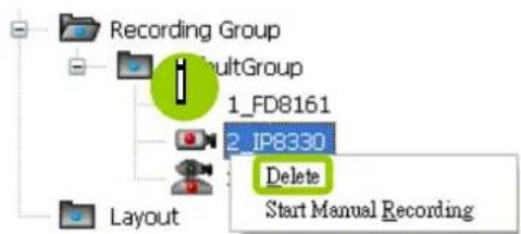
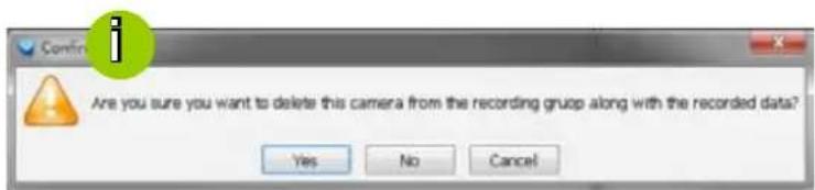
k. Delete recorded data older than the duration: If you only want to retain recorded data for a period of time, select this item and enter a number of day(s). In addition, since VAST Server will do "cyclic recording" automatically, the oldest file will be overwritten by the latest one when the capacity is full.
1. When completed, click Apply to confirm and save your settings. If you want to cancel all of your editing, click Restore to return to the previous settings or click close to discard the settings.
Add New Storage Group(s)
If you want to add a new storage group, click Add to give a name to the new storage group, which will be displayed on the drop-down list.
The following is an example of storage group list.
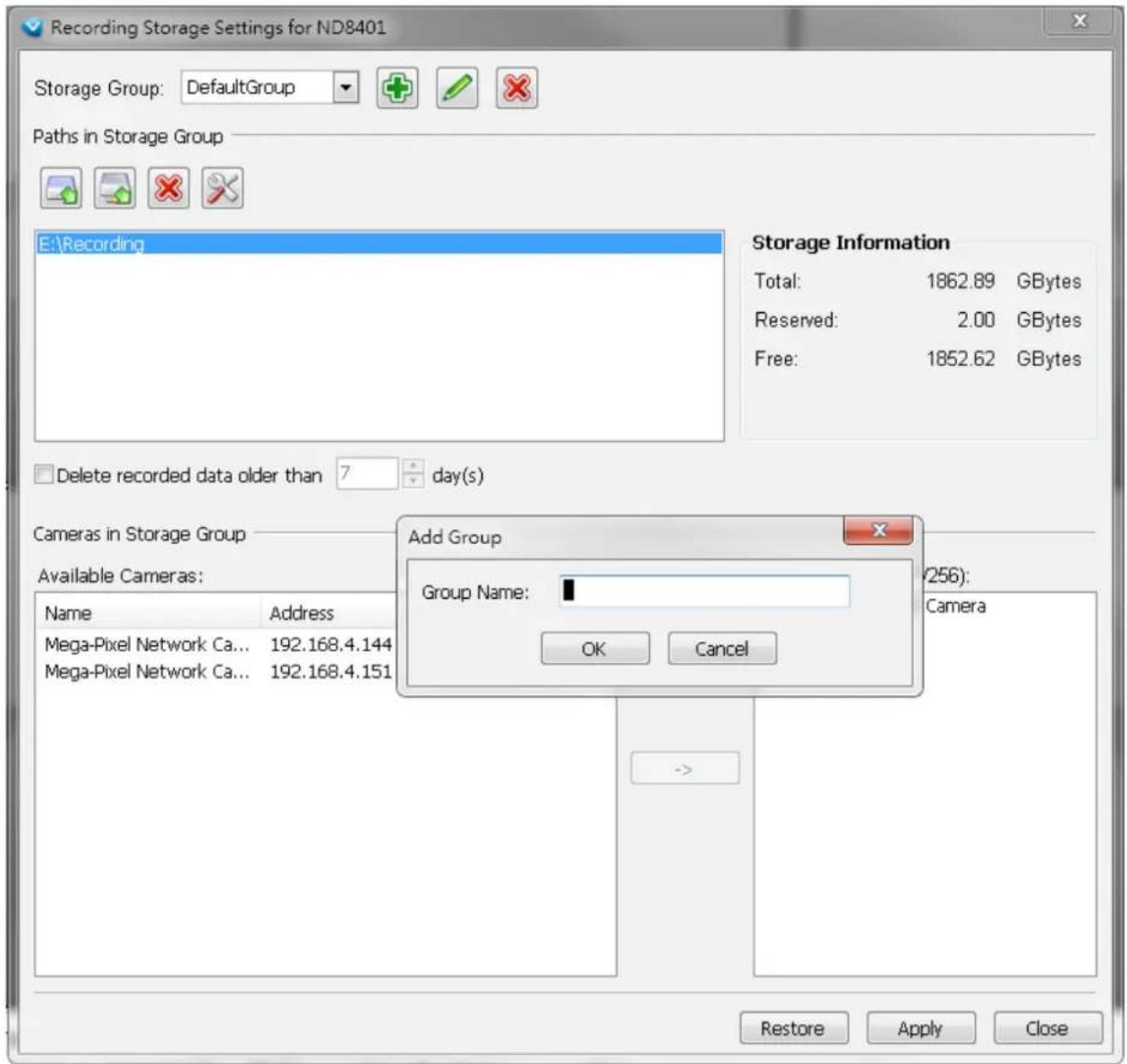

NOTE:
Please refer to the following limitations when you set up storage group(s):
■ One storage group can be assigned with several recording paths with the associated cylic recording function; while one recording path should only be assigned to one storage group.
How to Edit Recording Schedules
After editing recording storage settings, you can begin to edit recording schedules for the devices in a storage group. By default, all devices are assigned to the default recording schedule (Please refer to the default time frame settings on page 93). Therefore, once you insert a device to the station, the VAST Server will begin to record live video according to the default recording schedule. You can also manually remove a device from the default recording schedule. Please note that you cannot assign recording schedules to those devices which have been deleted from a Storage Group.
The following is an illustration of a set of recording schedules, which are composed of several time frames. Each time frame has its own time segments, period of time, repeat interval, and recording mode. You can create different recording schedules with simple or complex time frames based on your needs.
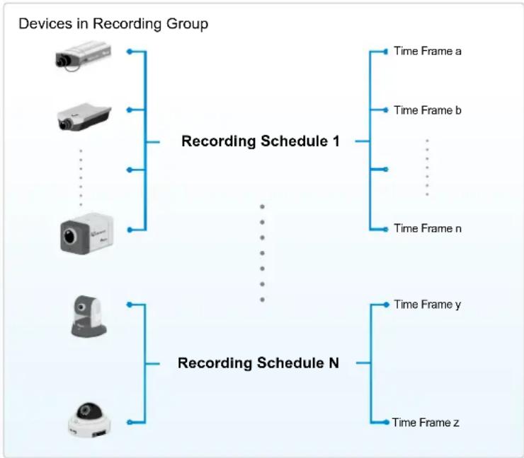
flowchart
graph TD
    A["Devices in Recording Group"] --> B["Recording Schedule 1"]
    A --> C["Recording Schedule N"]
    B --> D["Time Frame a"]
    B --> E["Time Frame b"]
    B --> F["..."]
    B --> G["Time Frame n"]
    C --> H["Time Frame y"]
    C --> I["Time Frame z"]
In addition, you can arrange the priority of each time frame according to its importance. The recording schedule with the highest priority will be applied first. This capability is very useful because you can specify a new time frame with the highest priority temporarily without modifying the other time frames.
Features of the recording schedules:
■ Each device can be assigned to only one recording schedule.
■ Each recording schedule may contain many time frames.
■ Each time frame has its own repetition frequency and recording mode.
To save time editing recording schedules and time-frames, we also provide a useful template function to save your time on schedules/time-frames settings. That is, you can save a specified schedule and download it as a template for future use or upload a well-arranged schedule template designed by others.
Please note that after you save the recording settings in the server, the recording schedule will automatically begin according to your settings.
Edit Schedule List
Please follow the steps below to set up the recording schedules:
a. Select the VAST station from the hierarchical device tree.
b. Click Configuration > Station Settings > Recording Schedule Settings on the menu bar (or right-click the station and select Station Settings > Recording Schedule Settings).
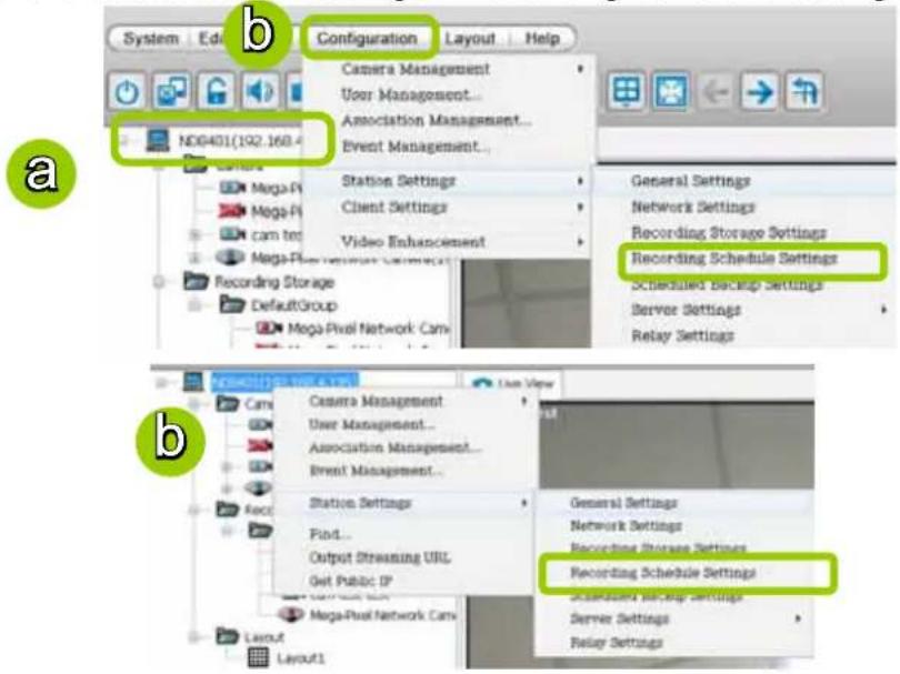
c. The Recording Schedule Settings window will prompt. By default, all cameras managed by the station will be assigned to Default Schedule, Default Time Frame, and Default Camera List.
Add Schedules
d. To add a new recording schedule, click Add to enter a name in the Schedule Name dialog box for the new schedule. Click OK to confirm the settings or Cancel to discard the settings. The new recording schedule will be displayed on the schedule drop-down list.
Rename Schedules
e. To rename an existing schedule, select the schedule from the schedule drop-down list and click Rename. A Schedule Name dialog will pop up for you to fill in a name for the new schedule. Click OK to confirm the settings or Cancel to discard the settings. The new recording schedule will be displayed on the schedule drop-down list.
Delete Schedules
f. To delete an existing schedule, select the schedule from the schedule drop-down list and click Delete. A Remove Schedule dialog box will pop up. Click OK to confirm or Cancel to discard the settings.
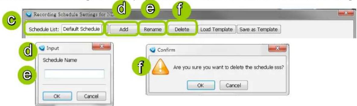
Load/Save Schedule Templates
g. If you have a schedule template with time frame settings, you can upload it to facilitate the scheduling process. Click Load Template, and a Load File dialog box will pop up. Select the template file and click Open to load.
h. If you want to save a schedule as a template for future use, select the schedule from the schedule drop-down list and click Save as Template. A Save File dialog box will pop up for you to save the template file.


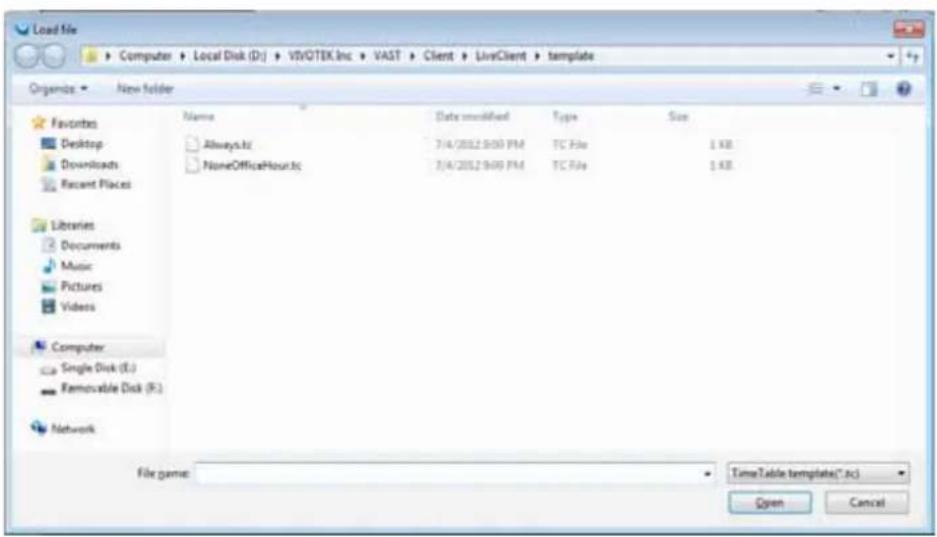
LiveClient provides two templates, Always and NoneOfficeHour. You can load and edit the time frame details.

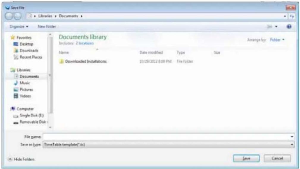
Edit Camera List
Please follow the steps below to assign a device to a recording schedule:
a. Select a recording schedule on the schedule drop-down list.
b. By default, all devices under the station are assigned to the Default Schedule.
c. Click << to remove devices from the Default Schedule. Click -> to add devices to the Default Schedule.
d. Click Apply to confirm or Close to discard the settings.
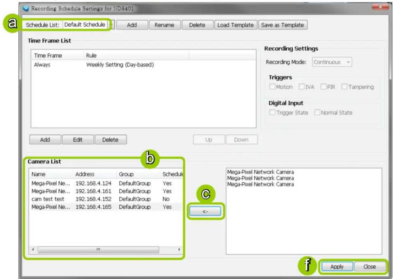
Edit Time Frame List
Default Time Frame: Weekly (Day-based), Mon.\~Sun., 24-hour, continuous recording
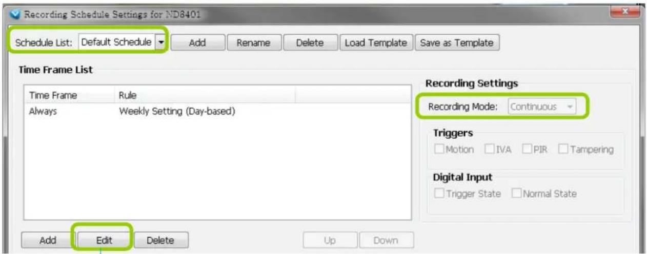
Click Edit to open the Default Time Frame settings page as shown below.
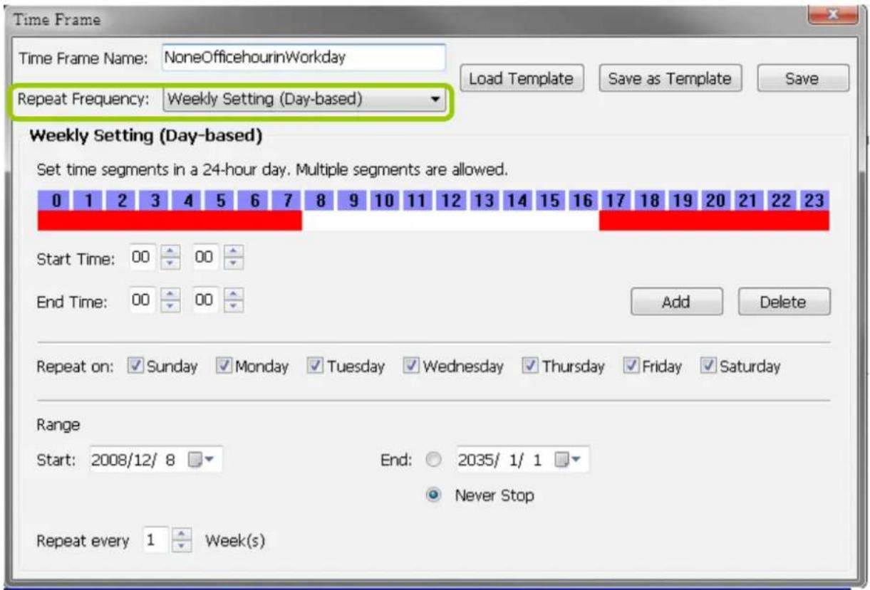
Add New Time Frames
Please follow the steps below to add new time frames to a schedule:
a. Select a recording schedule from the drop-down list.
b. Click Add to open the Time Frame Settings window.
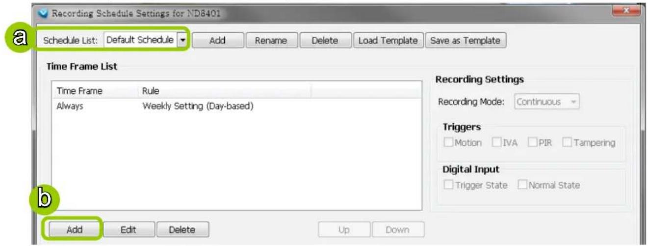
c. Enter a name for the new time frame.
d. If you have a time-frame template, you can upload it to simplify the editing of the schedule. Click Load Template and the Load File dialog box will pop up. Select the template file to load.
e. To edit the new time frame, select a Repeat Frequency from the drop-down list and edit the time segments, applicable days, applicable period of time, and repeat time interval. For the detailed settings of each repeat frequency, please refer to The Concept of Repeat Frequency on page 96.
f. When completed, click Save to enable the settings.
g. If you want to save this time frame as a template for future use, click Save as Template. A Save file dialog will pop up for you to save the template.
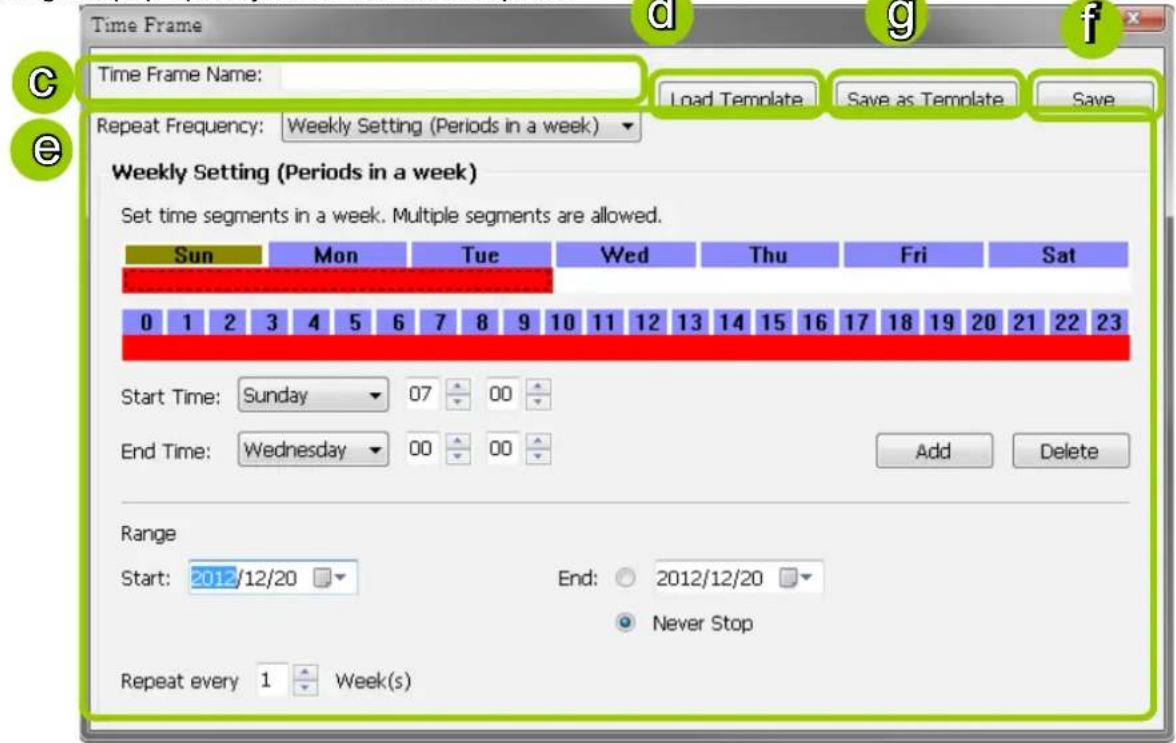
h. If you want to add additional time frames to the schedule, repeat the steps above.
i. Close the window when you finish the time frame settings.
j. Back to the Recording Schedule Settings window, the new time frame will be displayed on the Time Frame List.
k. If you want to edit an existing time frame, select if from the Time Frame List and click Edit to set up.
I. If you want to delete an existing time frame, select if from the Time Frame List and click Delete.
m. If you want to change the priority of a time frame, select it from the Time Frame List and click Up or Down to shift its position. The time frame on the top of the list has the highest priority.
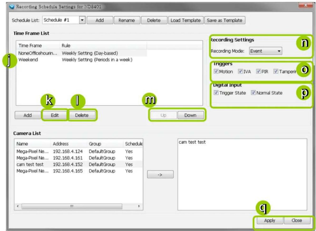
Recording Settings
n. Select one of the following Recording Modes for the time frame:
■ None: No recording action.
■ Continuous: 24-hours continuous recording. If you want to enable Activity Adaptive Streaming, please refer to page 88 for detailed illustration.
■ Event: The server will start to record only when an event is triggered. The recording time length depends on the settings in Recording Storage Settings. The default time length is 20 seconds (10s pre-event time plus 10s post-event time). Please refer to page 87 for more information. For more information about event categories, please refer to page 173 for detailed illustration.
o. Select Trigger Source(s): Motion Detection, IVA (Intelligent Video Analysis), PIR, and Tamper Detection
p. Select the status of Digital Input(s): Trigger State or Normal State
q. Click Apply to confirm the settings. Then close the window when you finish the recording schedule settings.

NOTE:
The following diagrams show the frame rate variations using two different recording modes:
- Continuous recording + Activity adaptive recording (helps save bandwidth and storage)
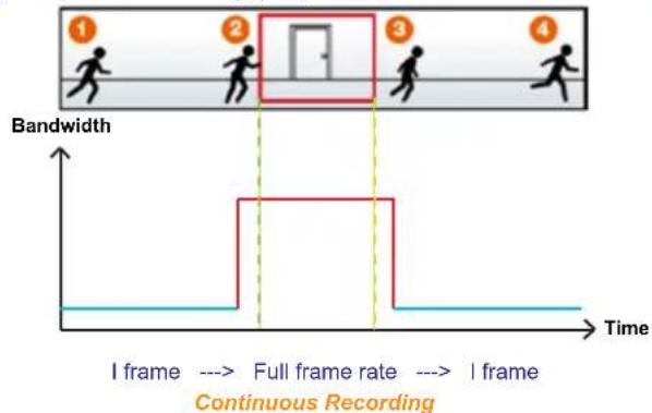
flowchart
graph TD
    A["1: Running Person"] --> B["2: Running Person"]
    B --> C["3: Running Person"]
    C --> D["4: Running Person"]
    style A fill:#f9f,stroke:#333
    style B fill:#ccf,stroke:#333
    style C fill:#cfc,stroke:#333
    style D fill:#fcc,stroke:#333
    note right of B: Full frame rate
    note right of C: I frame
    note right of D: Continuous Recording
- Event recording
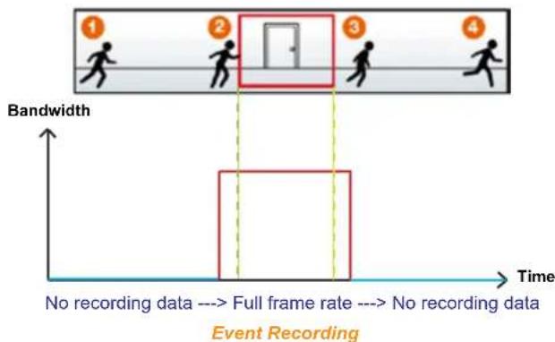
flowchart
graph TD
    A["1: No recording data"] --> B["2: Full frame rate"]
    B --> C["3: No recording data"]
    C --> D["4: No recording data"]
    style A fill:#f9f,stroke:#333
    style B fill:#ccf,stroke:#333
    style C fill:#cfc,stroke:#333
    style D fill:#fcc,stroke:#333
    note right of B: Full frame rate
    note right of C: No recording data
    note right of D: Event Recording
The Concept of Repeat Frequency
VAST offers the following types of repeat frequency. The definition of each type is listed in the following table:
| Repeat Frequency Discription | |
| Daily Setting | ■ Specify arbitrary time segments within a day,■ Repeat the segments every N days in the specified period of time. |
| Weekly Setting (Day-based)(Default Time Frame) | ■ Specify arbitrary time segments within a day,■ Apply only on selected days of a week,■ Repeat the segments every N weeks during the specified period of time. |
| Weekly Setting (Periods in a week) | ■ Specify arbitrary time segments within a week,■ Repeat the segments every N weeks during the specified period of time. |
| Monthly Setting (Day-based) | ■ Specify arbitrary time segments within a day,■ Apply only on selected days of a month,■ Repeat the segments every N months during the specified period of time. |
| Yearly Setting (Day-based) | ■ Specify arbitrary time segments within a day,■ Apply only on selected days of a year,■ Repeat the segments every N years during the specified period of time. |
Repeat Frequency: Daily Setting
To set up daily repeat frequency, please configure the following items: Daily time segments, applicable period of time, and repeat time interval.
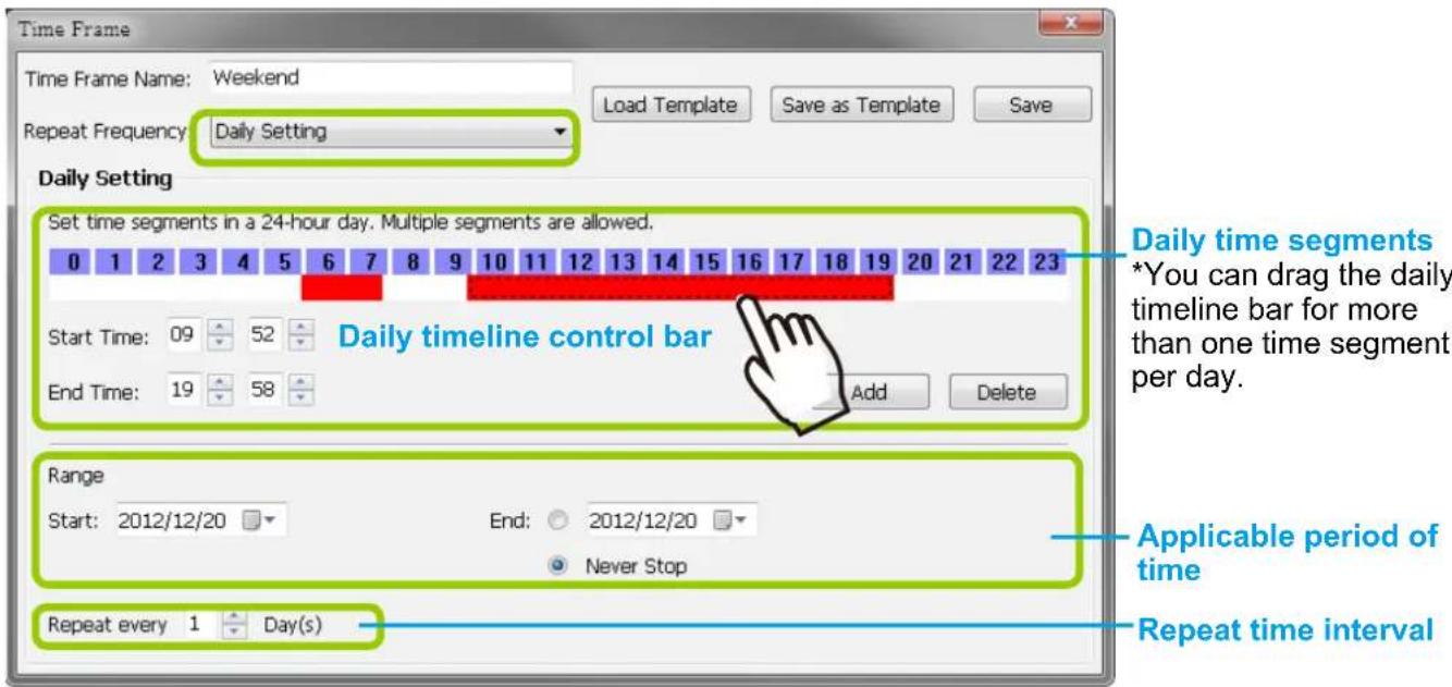
Set up daily time segments
You can specify several time segments within a day. The numbers 0\~23 on the hourly timeline control bar (the purple rectangles) represent the 24 hours in a day.
There are two ways to define time segments: one is to use the computer mouse to manipulate the timeline control bars; the other is to fill in the precise start and end time values in the corresponding fields.
Add time segments: Choose either step 1 or step 2 to set up
- Use the mouse to drag the timeline bars:
a. Left-click the daily timeline control bar (the purple rectangles) and drag the mouse.
b. The corresponding time segment will also appear in the Start Time and End Time fields. Click Add, then the red timeline bars representing new time segments will appear as shown below. You can drag multiple time segments within a day.
In the following illustration, the yellow arrows show the dragging direction of the mouse. You can drag from left to right or the opposite.

- Fill in the precise Start Time and End Time:
a. Directly enter the value in the Start Time and End Time fields, then click Add.
b. The corresponding red timeline bar will automatically appear as shown below.

Delete time segments: Choose either step 1 or step 2 to set up
- Use the mouse to erase the timeline bar: Right-click on an existing red timeline bar and drag the mouse. A green timeline bar representing the deleted part of the time segment will erase the red bar as shown below.
In the following illustration, the green arrows show the dragging direction of the mouse. You can drag it from left to right or the opposite.
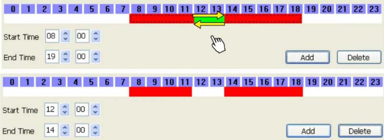
- Use the delete button to remove the entire timeline bar:
a. Click an existing red timeline bar or left-click the daily timeline control bar (the purple rectangles) and drag the mouse.
b. The corresponding time segment will appear in the Start Time and End Time fields.
c. Click Delete, and the selected timeline bar will disappear.
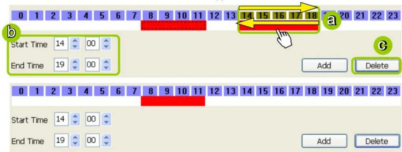
Set up applicable period of time
For repeat frequencies, you can set up the applicable date and period of time for the time frame.
a. Specify the start date and time in the Start field. A calendar date selector will appear when you click on the drop-down list of date. Click < or to select the month, then pick a desired day in the calendar.
b. Specify the end date and time in the End field if you have an end time for applying this time frame. If you do not have a terminating time for this time frame, select Never Stop.
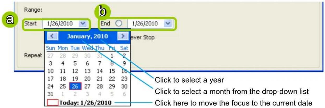
Set up repeat time interval
The repeat time intervals is "every N day(s)" as shown below. Repeat every 1 day means the time frame would apply for every day within the period of time.

Repeat Frequency: Weekly Setting (Day-based)
To set up Weekly (Day-based) repeat frequency, please configure the following items: Daily time segments, applicable days within a week, applicable period of time, and repeat time interval.
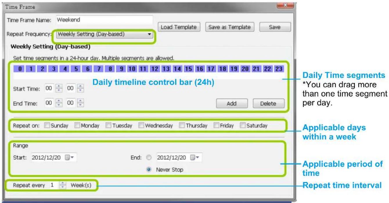
Set up daily time segments
Please refer to page 97 for detailed instructions.
Set up applicable days within a week
For repeat frequency--"Weekly (day based)", you can apply the time segments only on selected days of the week.
Repeat on □Sunday □Monday □Tuesday □Wednesday □Thursday □Friday □Saturday
Set up applicable period of time
Please refer to page 99 for detailed instructions.
Set up repeat time interval
The repeat time intervals is "every N week(s)" as shown below. Repeat every 1 week means the time frame would apply for every week within the period of time.
Repeat every 1 Week(s)
Repeat Frequency: Weekly Setting (Periods in a week)
To set up Weekly (Periods in a week) repeat frequency, please configure the following items: Time segments within a week, applicable period of time, and repeat time interval.
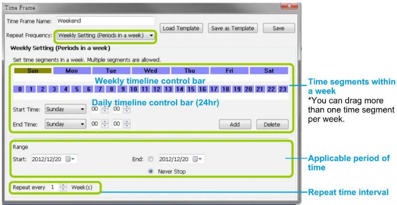
Set up time segments within a week
You can specify several time segments within a week. The weekly timeline control bar represents the 7 days of a week, and the daily timeline control bar represents the 24 hours in a day. The daily timeline control bar is only valid when one of the days on the weekly timeline control bar has been selected.
There are two ways to set up time segments: one is to clicking and holding down the left mouse button to draw the timeline control bars; the other is to fill in the precise start and end time value in the corresponding fields.
Add time segments: Choose either step 1 or step 2 to set up
- Use the mouse to drag the timeline bars:
a. Click on a day on the weekly timeline control bar. The selected bar will turn green.
b. Left-click the daily timeline control bar and drag the mouse.
c. The corresponding time segment will also appear in the Start Time and End Time fields. Click Add, then the red timeline bars representing new time segments will appear as shown below. You can drag multiple time segments within a day and a week.
In the following illustration, the yellow arrows show the dragging direction of the mouse. You can drag from left to right or the opposite.
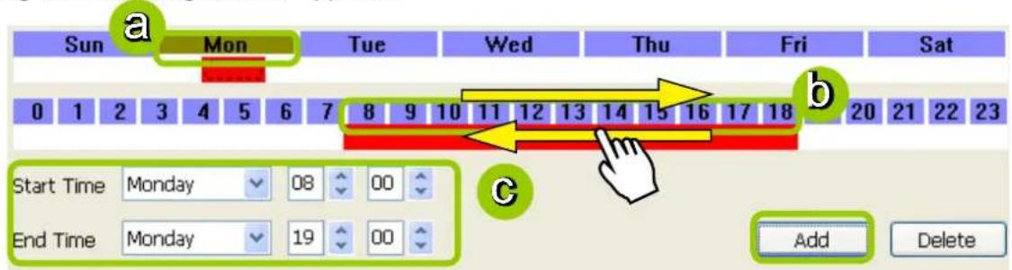
- Fill in a precise Start Time and End Time:
a. Directly select a day and enter the value in the Start Time and End Time fields, then click Add.
b. The corresponding red timeline bars will automatically appear as shown below.
The following is an example of an extended time segment from Mon. 8:00 to Fri. 19:00.
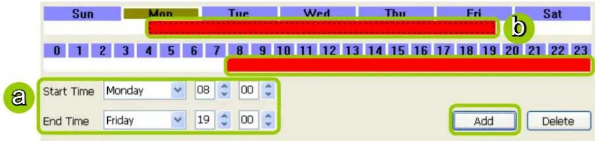
Delete time segments: Please refer to page 98 for detailed instructions.
Set up applicable period of time
Please refer to page 99 for detailed instructions.
Set up repeat time interval
Please refer to page 100 for detailed instructions.
Repeat Frequency: Monthly Setting (Day-based)
To set up Monthly (Day-based) repeat frequency, please configure the following items: Daily time segments, applicable date(s) of a month/day(s) of a week, applicable period of time, and repeat time interval.
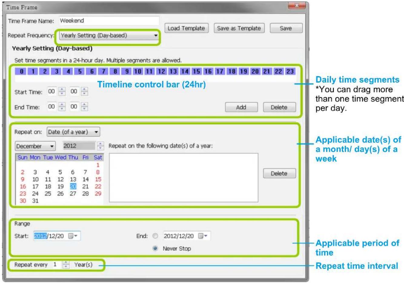
Set up daily time segments
Please refer to page 97 for detailed instructions.
Set up applicable date(s) of a month/ day(s) of a week
For repeat frequency--"monthly (day-based)", you can apply the time segments only on selected days of a month. There are two types of repeat frequencies: Date(s) of a month and Day(s) of a week.
Repeat by date(s) of a month:
Select date(s) from the calendar, and it will be displayed on the right blank as shown below. The following example refers to the 1^st 5^th day of a month.
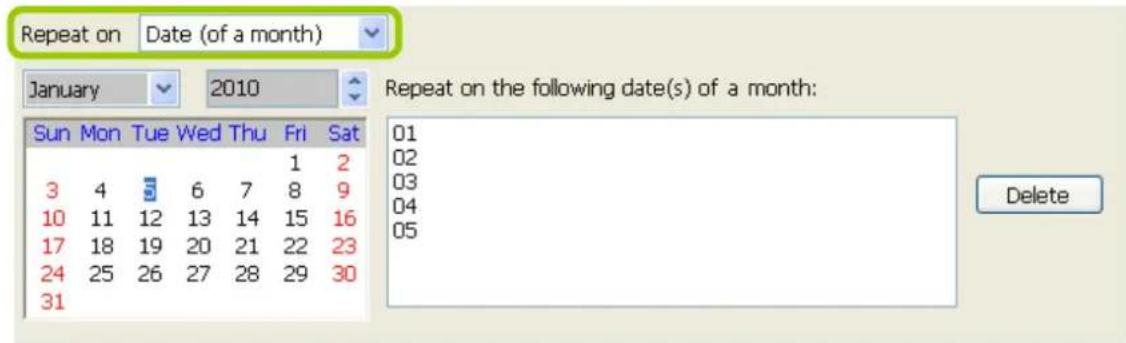
Repeat by day(s) of a week:
Select day(s) from the calendar, and it will be displayed on the right blank as shown below. The following example refers to the 1^st 5^th Friday of a month.
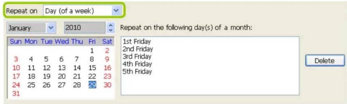
Set up applicable period of time
Please refer to page 99 for detailed instructions.
Set up repeat time interval
The repeat time intervals is "every N month(s)" as shown below. Repeat every 1 month means the time frame would apply for every month within the period of time.

Repeat Frequency: Yearly Setting (Day-based)
To set up Yearly (Day-based) repeat frequency, please configure the following items: Daily time segments, applicable date(s) of a year/ day(s) of a week, applicable period of time, and repeat time interval.
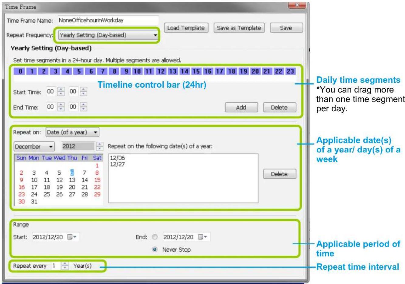
Set up daily time segments
Please refer to page 97 for detailed instructions.
Set up applicable date(s) of a year/ day(s) of a week
For repeat frequency--"yearly (day-based)", you can apply the time segments only on selected days of a year. There are two types of repeat frequencies: Date(s) of a year and Day(s) of a week.
Repeat by date(s) of a year:
Select date(s) from the calendar, and it will be displayed on the right blank as shown below. The following example refers to the 1^st 5^th day of a year.
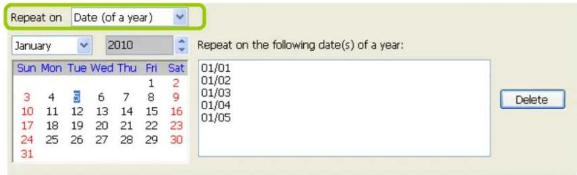
Repeat by day(s) of a week:
Select day(s) from the calendar, and it will be displayed on the right blank as shown below. The following example refers to the January 1^st 5^th Friday of a year.
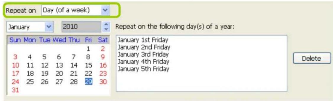
Set up applicable period of time
Please refer to page 99 for detailed instructions.
Set up repeat time interval
The repeat time intervals is "every N year(s)" as shown below. Repeat every 1 year means the time frame would apply for every year within the period of time.

How to Manually Begin /Stop Recording
By default, all devices are assigned to the default recording storage and default recording schedule. Therefore, once you included a camera into the NVR's configuration, the VAST Server will begin to record live video according to the default recording schedule. Please refer to How to Edit Recording Schedules on page 89.
However, if you have changed the default schedule, you can manually click Manually Begin Recording to enable a device without setting up a recording schedule. Please follow the instructions below to manually begin recording.
Select the device from the hierarchical device tree under the Default Group, then click Edit > Manually Begin Recording on the menu bar (or right-click the device and select Manually Begin Recording). The text on the menu bar will turn into Manually Stop Recording as shown below and the VAST Server will start to record video from the target camera. Please note that its priority will be higher than the recording schedule, and the recording task will continue unless you click on Manually Stop Recording. After you click Manually Stop Recording, the device will then follow the preset recording schedule.
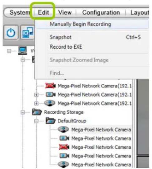
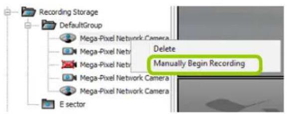
How to Edit Scheduled Backup Settings
VAST LiveClient supports scheduled backup which allows the user to back up the recorded data in another disk.
Please follow the steps below to enable scheduled backup settings:
a. Select the target station from the device tree.
b. Click Configuration > Station Settings > Scheduled Backup Settings on the menu bar (or right-click the station and select Station Settings > Scheduled Backup Settings).
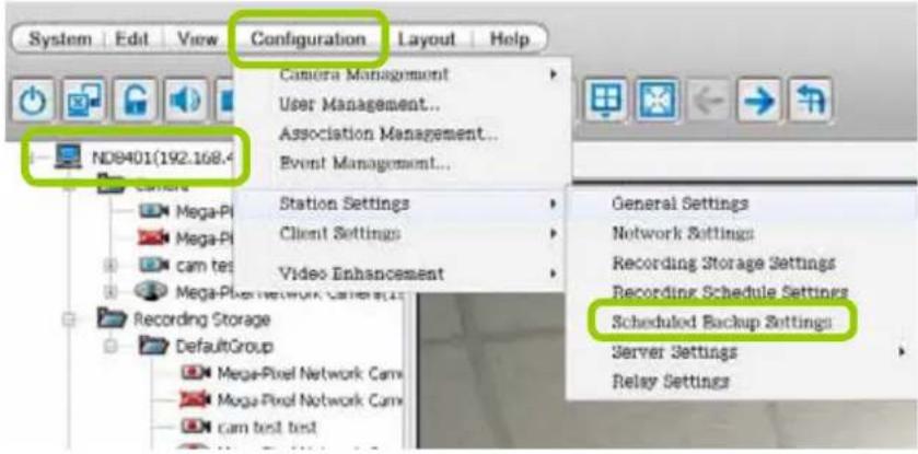
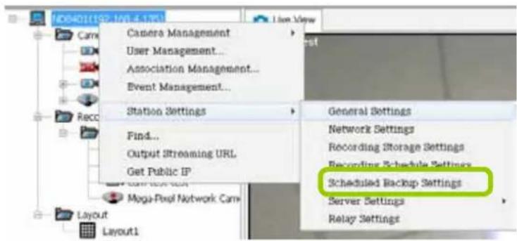
c. The Scheduled backup settings window will prompt.
Select Backup Source
d. Check Enable schedule backup.
e. Select the data source you want to backup. If you check Selected cameras, you can click >> or << to choose the data source that you want to backup.
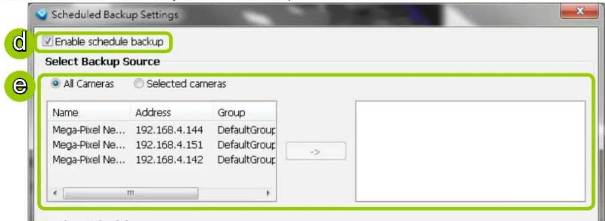
Setup Backup Schedule
f. Fill in a desired time and click >> to add the backup time. Please note that the backup time interval must not be shorter than 1 hour. For example, 23:40 and 00:15 are not allowed to exist simultaneously. In the sample below, the server will backup the recorded data at 12:00 PM and 23:00 PM everyday once you save the settings.


NOTE:
The following diagram shows the backup schedule and backup data:

flowchart
graph LR
    A["Server start"] --> B["1st backup data"]
    B --> C["2nd backup data"]
    C --> D["3rd backup data"]
    D --> E["4nd backup data"]
    E --> F["..."]
    style A fill:#FFD700,stroke:#333
    style B fill:#B2C2F2,stroke:#333
    style C fill:#FFD700,stroke:#333
    style D fill:#FFD700,stroke:#333
    style E fill:#FFD700,stroke:#333
    style F fill:#FF6347,stroke:#333
Select Backup Target
g. Click Browse... to select a path (local path or network storage) to store the backup data. Please note that the disk for backup data should be different from the original recording path, or a warning message will pop up as shown below. For more information about how to set up recording path, please
refer to page 85. Note that you should not select disk C:\ or D:\ as the backup target. C:\ and D:\ are for system programs and database.
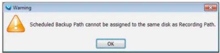
h. Select a maximum size for backup folder. The server will divide backup data into the following size: VCD (650M), DVD (4.7G), Customize, or Unlimited size according to your choice.
i. Select Delete old backups if space is insufficient if you want to do cylic backup due to the limited size of the hard disk.
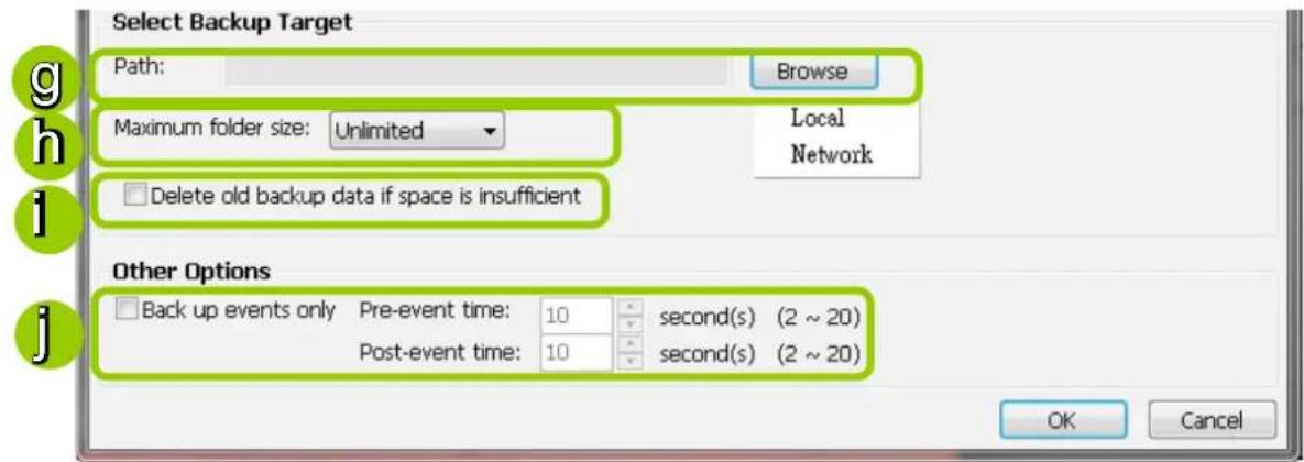
Other Options
j. If you only want to backup the recorded data of events, select Backup only events and fill in the pre- and post-event time.
How to Configure Station Server Settings
VAST LiveClient supports Server Settings including DDNS Settings, Network Storage Settings, and SMTP Settings.
Select the station from the hierarchical management tree and click Configuration > Station Settings > Server Settings to open the page (or right-click the station and select Station Settings > Server Settings).
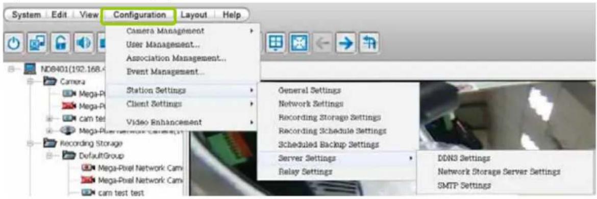
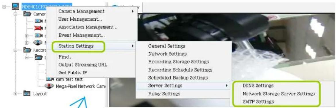
DDNS Settings
Since a public IP assigned to the NVR WAN port may be a dynamic IP address, using DDNS service for it will benefit from a fixed domain name.
Select a DDNS provider from the provider drop-down list. VIVOTEK offers 2bthere.net (Safe100.net), a free dynamic domain name service, to VIVOTEK customers. Please refer to the user's manual of VIVOTEK's network camera for detailed DDNS settings.
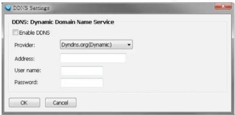
Network Storage Server Settings
The VAST Server allows user to set up network storage path(s) for recorded files. Please follow the steps below to add a new network storage path.
a. Click Add to open the Network Host Window.
b. Fill in the related information for the network host. Then click OK to save the new settings.
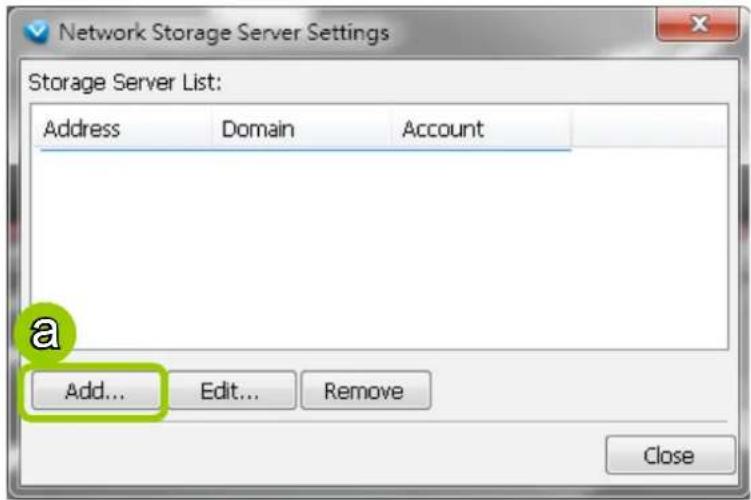
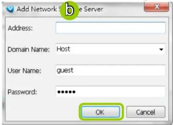
c. If you want to add more network host(s), please repeat step a. b.
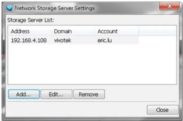
SMTP Settings
VAST Server allows user to set up SMTP Server to send mail alert when event triggers. For more information about how to set up event management, please refer to page 73.
Please follow the steps below to configure the SMTP Server:
a. Click Add to open the SMTP Settings page.
b. Enter the related information of your mail server. If your SMTP server requires a secure connection (SSL), check Use SSL.
c. Click OK to enable the settings.
d. Then the new information will appear on the SMTP Settings window as shown below.
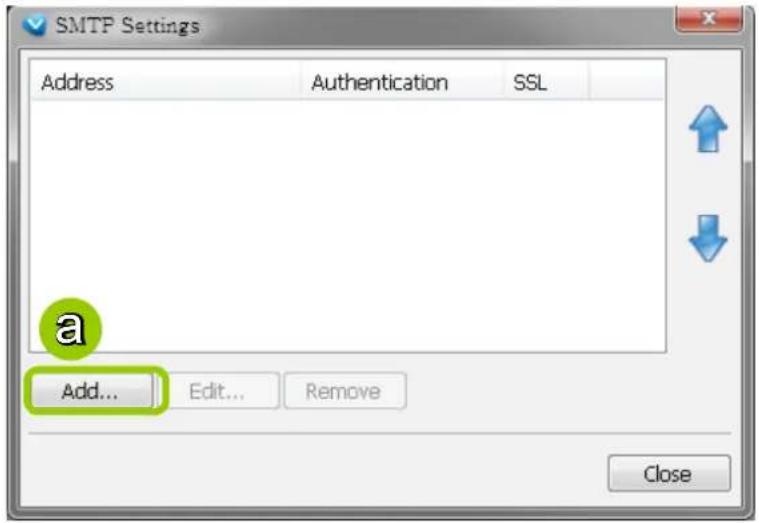
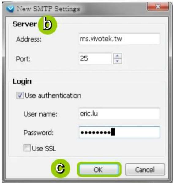
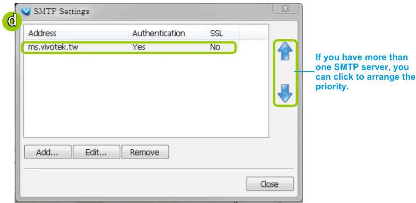
How to Use the Talk Panel
VAST LiveClient supports the two way audio function which allows the user to communicate with people around the network camera. Please enable the two way audio function on the camera side. Below is a conceptual drawing of the two way audio function:
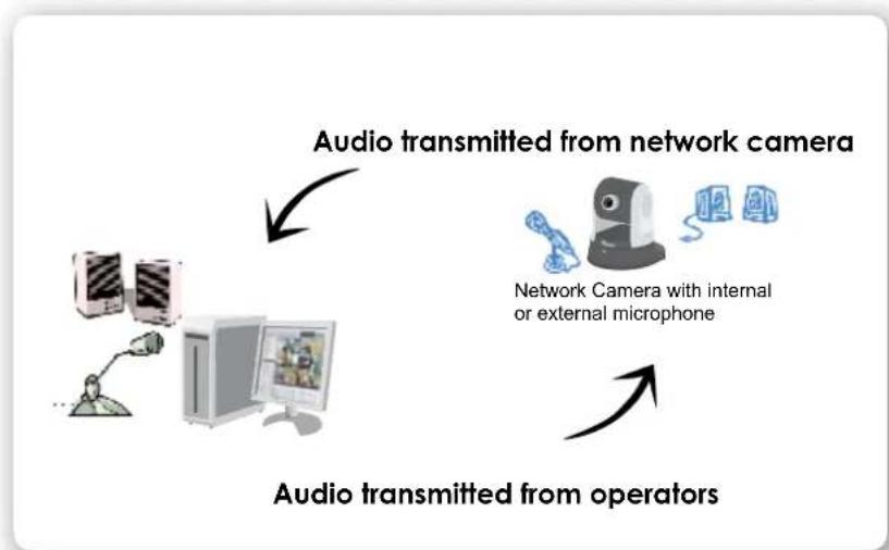
flowchart
graph TD
    A["Computer with monitor"] -->|Audio transmitted from network camera| B["Network Camera with internal or external microphone"]
    B -->|Audio transmitted from operators| C["Operator with microphone"]
Add a Camera to the Talk Panel
■ There are several ways to add a Network Camera to the Talk Panel:
Drag-and-drop a camera from the video cell or from the hierarchical device tree to the talk panel as shown below. You can also right-click the target camera or the video cell, then click Send to Talk Panel on the popup menu.
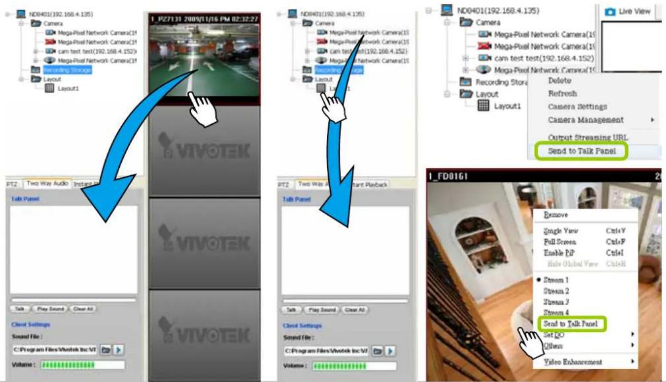
■ An icon with the camera name will be displayed in the Talk Panel.
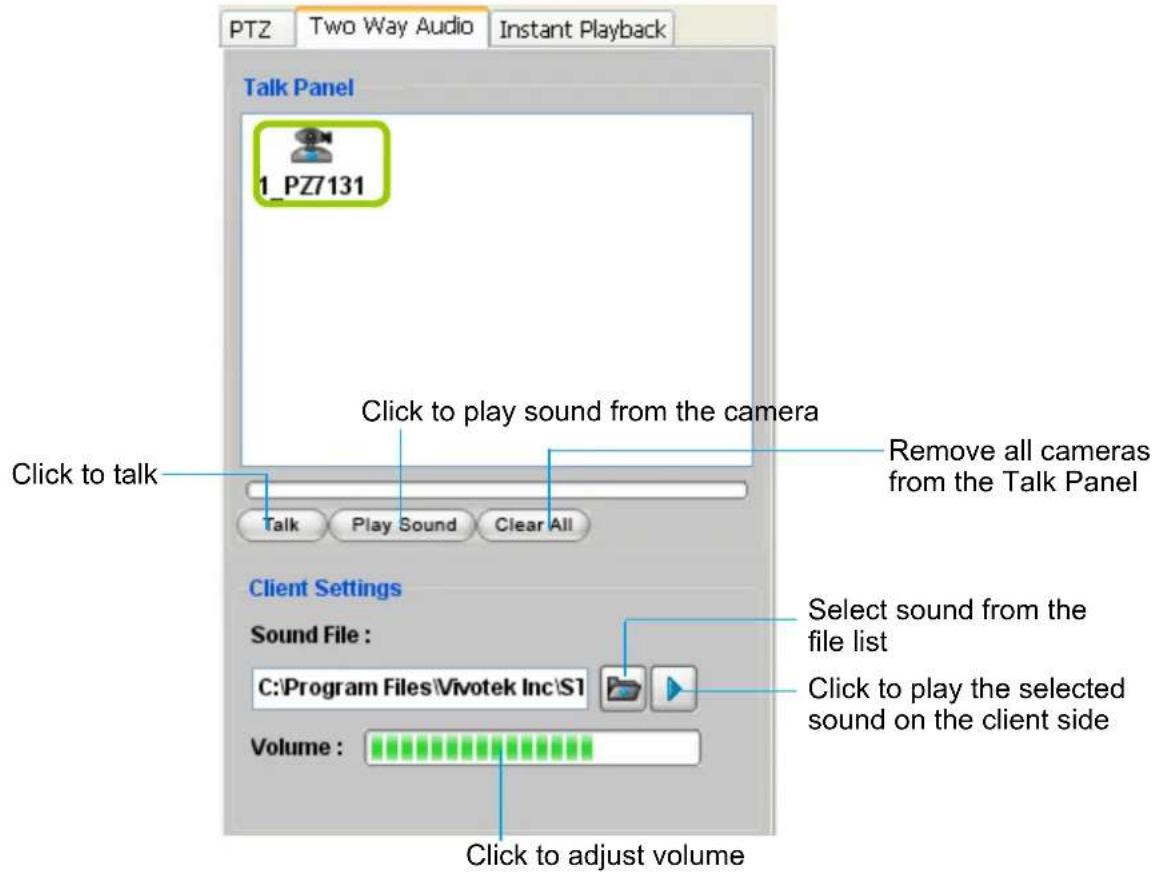

NOTE:
■ Please note that you cannot Talk and Play Sound at the same time.
■ When you are talking or playing sound, you cannot add other cameras to the Talk Panel. If you want to add more cameras to the Talk Panel, please Stop Talking and Stop Playing first.
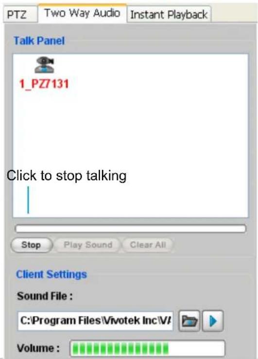
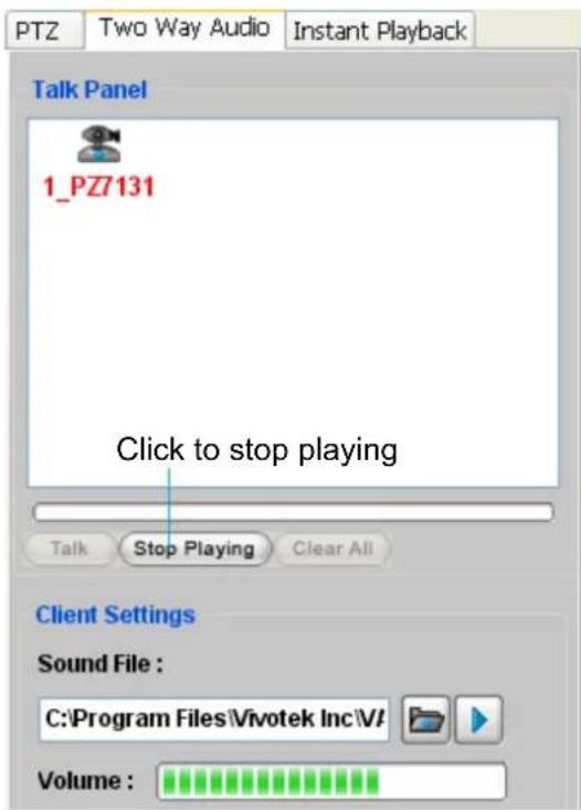
Remove a Camera from the Talk Panel
■ Remove a camera
Drag a camera from the Talk Panel and drop to the hierarchical management tree window as shown below. The camera icon will disappear.
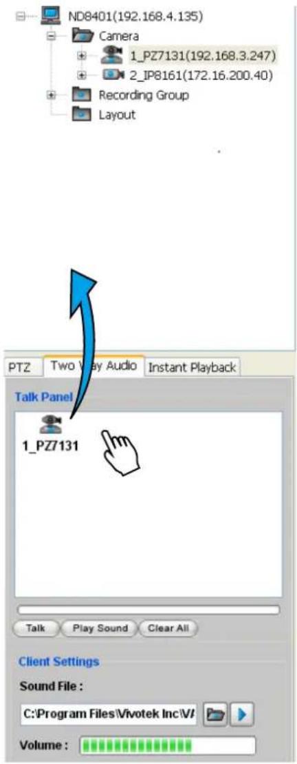
■ Remove all cameras
Click , all cameras in the Talk Panel will be removed.
How to Configure E-map Settings
VAST LiveClient supports intuitive E-map function which allows users to upload E-maps for overall devices management.
Click System > E-map to open E-map Settings Page:
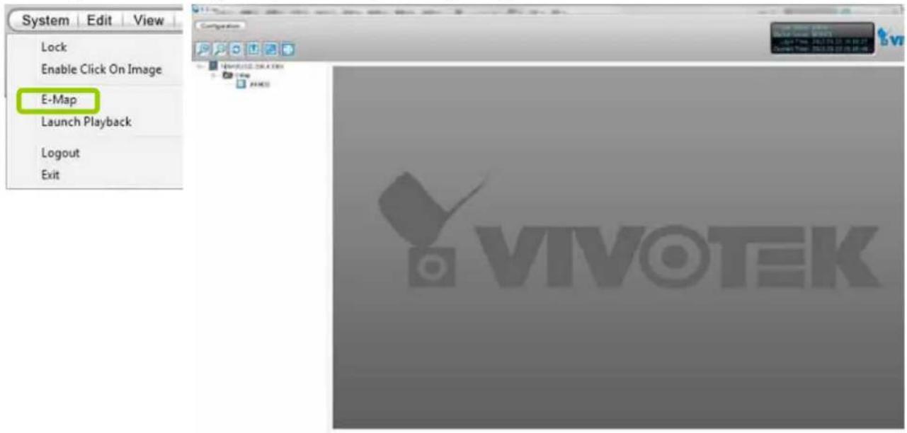
Upload an E-map
Click to search for E-map(s) to upload.
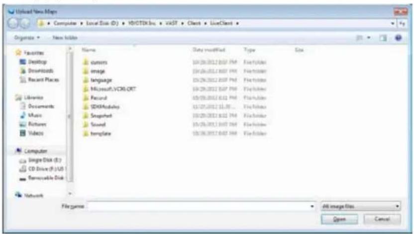
The uploaded E-maps will be listed under the E-map list tree.

NOTE:
If the uploading procedure fails, please compress the image size of your map (equal or smaller than 2MB) and try again.
E-map Settings Page (View Mode)
■ Double-click an E-map on the tree, it will be displayed on the E-map window as shown below. There are two operation modes of E-map settings page: "View Mode" and "Edit Mode". The following is the "View Mode" illustration.
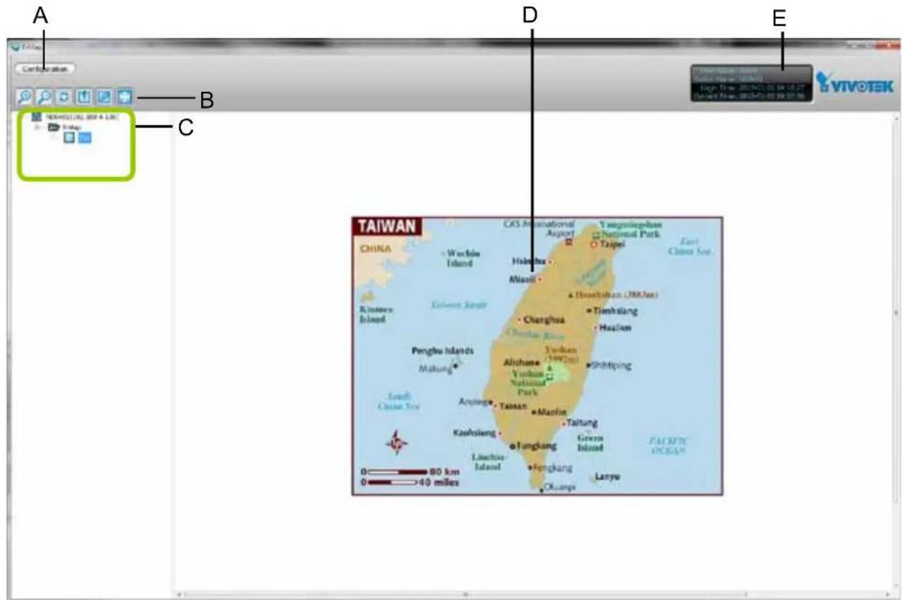
A. Menu bar
B. Quick access bar
C. E-map list tree
D. E-map window
E. Status panel
■ Right-click the E-map, then you can edit, rename, or delete the E-map.
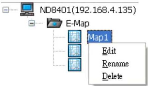
Quick Access Bar

Icon Function Description


Zoom in Zoom in the E-map
Zoom out Zoom out the E-map
Default size Adjust the E-map to default size
Upload Upload E-map to the login station
View Mode Click to switch to view mode
Full Screen Extend the E-map settings page to full screen
Save Save E-map settings
Status Panel
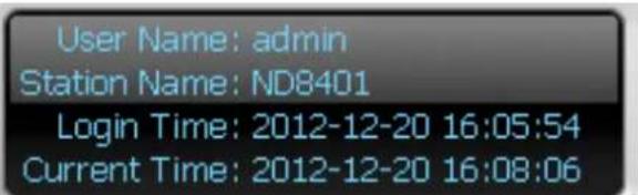
| User Name |
| Station Name (IP Address) |
| Login Time (yyyy-mm-dd hh:mm:ss) |
| Current Time (yyyy-mm-dd hh:mm:ss) |
E-map Settings Page (Edit Mode)
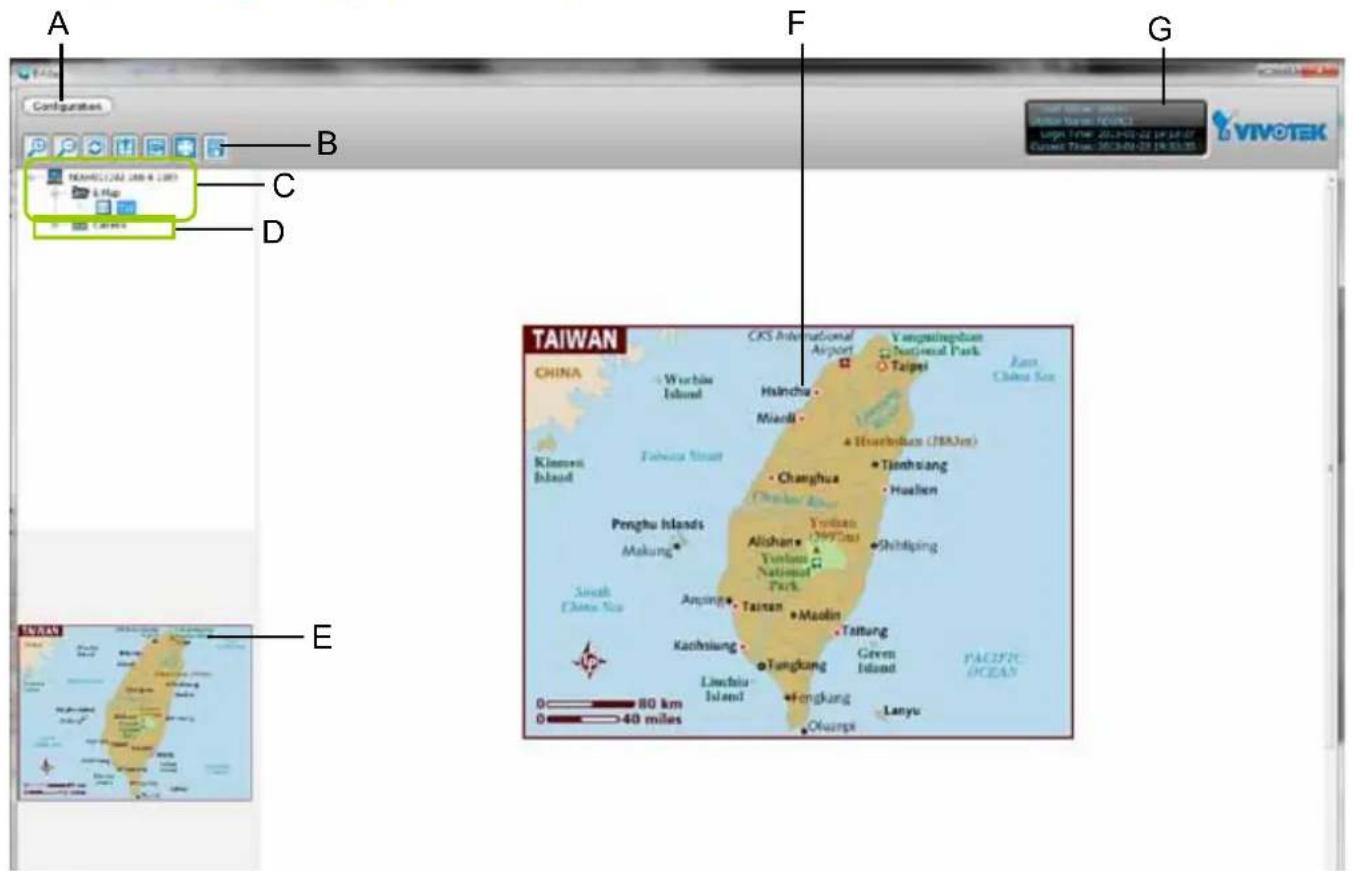
A. Menu bar
E. Map preview
B. Quick access bar
F. E-map window
C. E-map list tree
G. Status panel
D. Device tree
■ Right-click the E-map, you can delete an existing E-map.
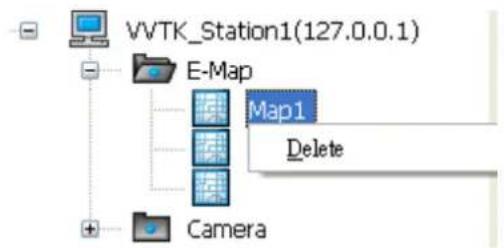
Device Management
Please follow the steps below to edit an uploaded E-map.
a. Double-click the E-map you want to edit, it will be displayed on the E-map window.
b. Use Quick Access Bar to adjust the size of the E-map. In edit mode, you can also use your mouse to drag the position of the E-map and zoom in or zoom out the E-map.
c. Drag-and-drop the connected devices to the E-map according to your deployment.
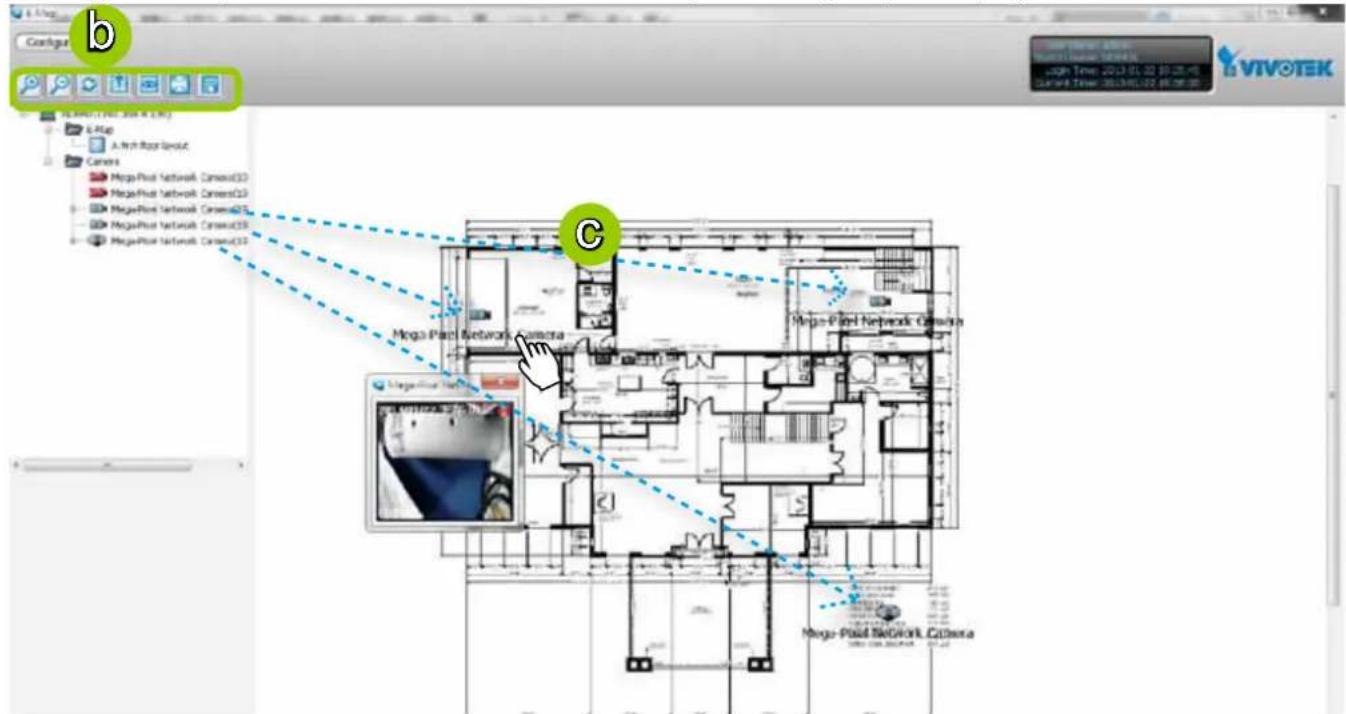
d. Right-click the device icon on E-map, you can rotate the direction or delete the device. The device can be rotated in 8 derections as shown below.


e. You can also drag the DI/DO device under the connected device onto the E-map. If you want to change the status of the DO device, double click the DO icon on E-map.
For more information about DI/DO settings, please refer to Association Management on page 71.
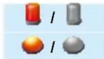
Digital input on / off
Digital output on / off
f. Click 📋 on the Quick Access Bar to save the new settings.

NOTE:
The red frame twinkling around the device means there is event trigger(s) going on. Meanwhile, a live view dialog will pop up beside the model.
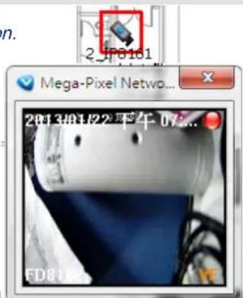
Live View Dialog Settings
Click System > E-map Settings to open the E-map Settings dialog, then you can choose to Open Live View Dialog or to Send to Single View when you double-click the device deployed on the E-map.
Open Live View Dialog
Select Open Live View Dialog: When you double-click the device icon on the E-map or when an event triggers, a live view dialog will pop up beside it. It is the default setting in E-map Settings window.
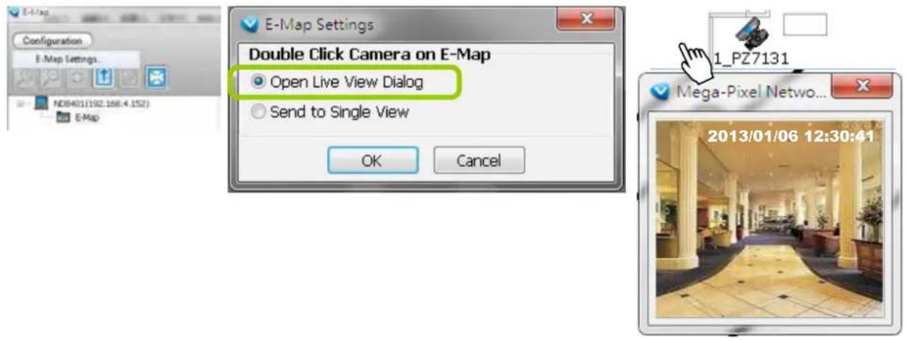
Send to Single View
Select Send to Single View: When you double-click the device icon on the E-map, it will open a single view on the VAST LiveClient.
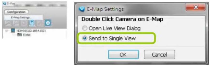

NOTE:
The live view dialog also supports click on image, PTZ, and e-PTZ as long as the connected camera also supports and has enabled these functions. To enable those function on E-map, please check the item "Enable click on image" on the menu bar of LiveClient as shown below. Then an icon will appear in the live view dialog for you to control the cameras.
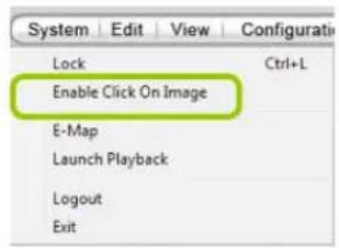
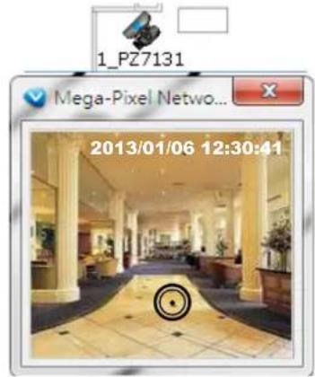
E-map Link
After completing device deployment on your E-map, you can link an E-map to another E-map. Please follow the steps below to configure E-map link:
a. Select a map you want to edit and enter Edit Mode.
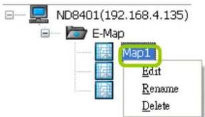
b. Drag-and-drop another E-map onto current E-map. A blue frame will appear as shown below. For example: Link Map1 to Map2 by dargging Map2 onto Map1
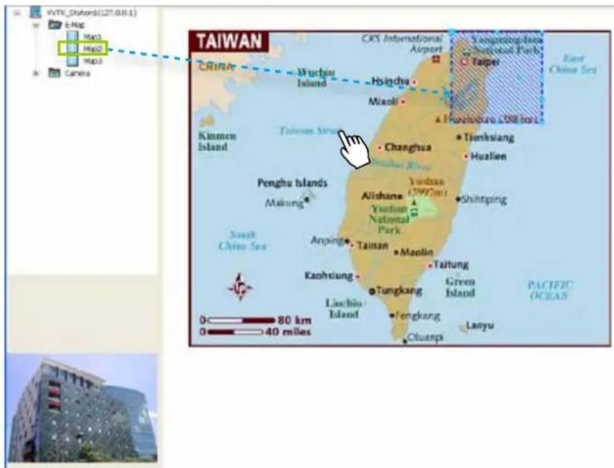
c. Use ⏻ to move the position of the blue frame.
d. Right-click the blue frame to Resize or Delete it.

Click Resize, some nodes will appear around the blue frame. Then You can drag the nodes to move the position, rotate the direction, adjust the size, and change the shape.
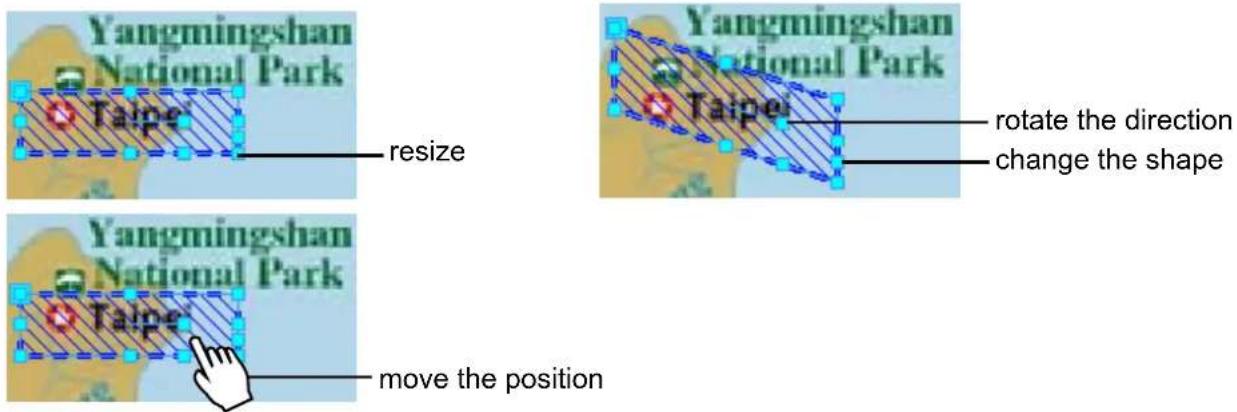
e. Click on the Quick Access Bar to save the new settings.
f. If you want to set additional map links, please repeat steps a. \~ e. For example: Link Map2 to Map3 by dargging Map3 onto Map2
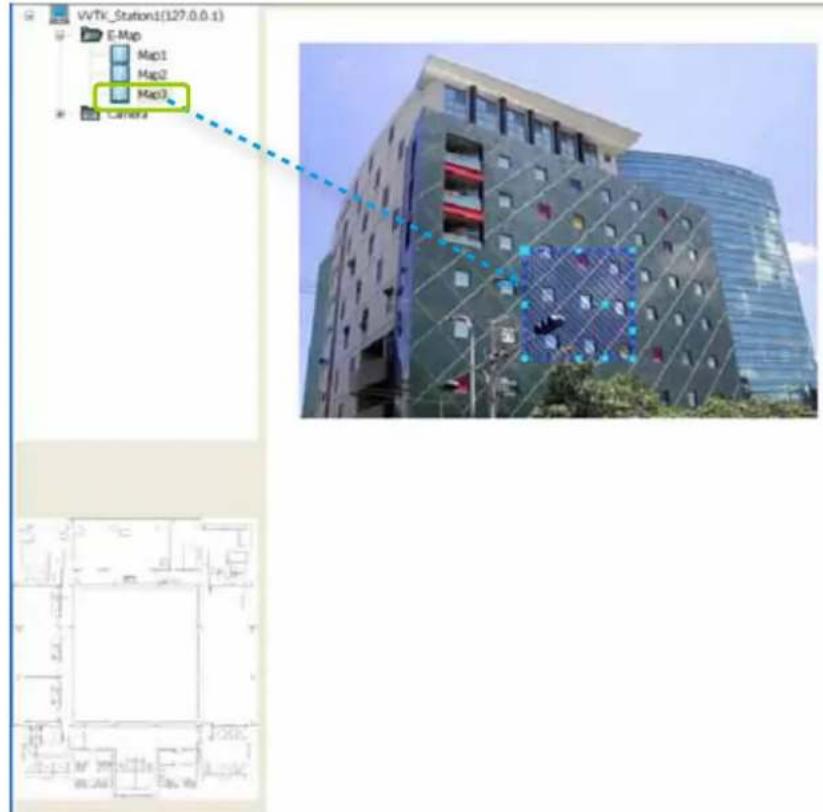
g. Click 📋 on the Quick Access Bar to save the new settings.
h. Test the web links. Click on the Quick Access Bar to switch to view mode.
Double-click the blue frame on Map1, it will automatically switch to map2. Then double-click the blue frame on Map2, it will automatically switch to map3.
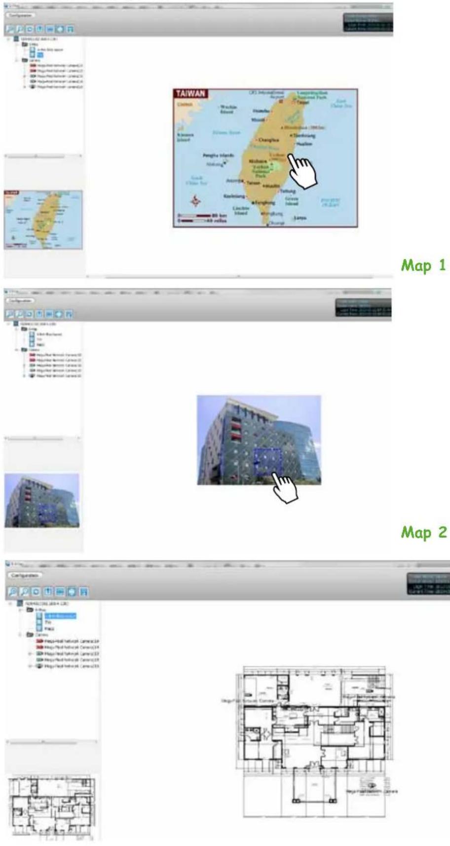
Map 3
How to Configure Client Settings
In Client Settings, you can configure Snapshot Settings, Recording Settings, View Settings, General Settings, Joystick Settings, Proxy Settings, and PiP Settings.
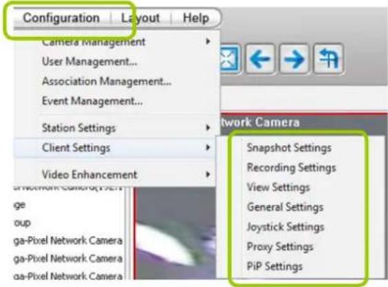
Snapshot Settings
Please follow the steps below to configure snapshot settings:
a. Click Configuration > Client Settings > Snapshot Settings on the menu bar to open the Snapshot Settings window.
b. Select a picture format for snapshots (BMP or JPEG). If you select JPEG format, you can adjust the recompression quality (from 1 to 100). Note that a higher value would generate higher picture quality but lower compression rate.
c. Fill in a filename prefix for the snapshots.
d. The default storage path for snapshots is E:\UserData\Snapshot. You can not change target directory.
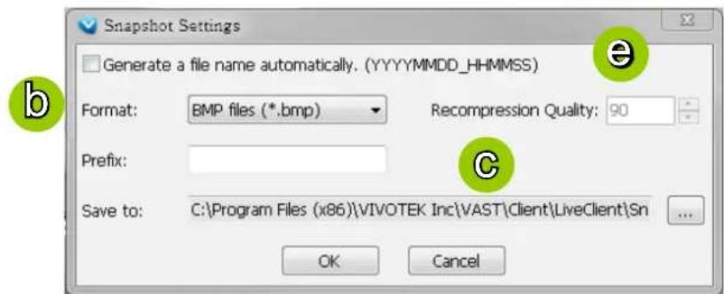

NOTE:
The recompression quality is only enabled in H.264 streaming. If your stream source is MJPEG, the system will directly save the JPEG image without recompression.
e. If you check Generate a file name automatically, NVR will directly save snapshots with the following filename format to the storage folder.
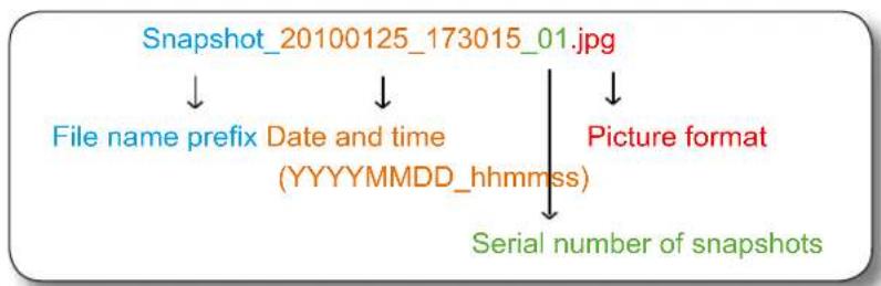
flowchart
graph TD
    A["Snapshot_20100125_173015_01.jpg"] --> B["File name prefix"]
    B --> C["Date and time (YYYYMMDD_hhmmss)"]
    C --> D["Serial number of snapshots"]
    A --> E["Picture format"]
If you uncheck Generate a file name automatically, the Save file dialog box will pop up when you take a snapshot. The file name prefix will automatically be displayed in the Save File dialog box.
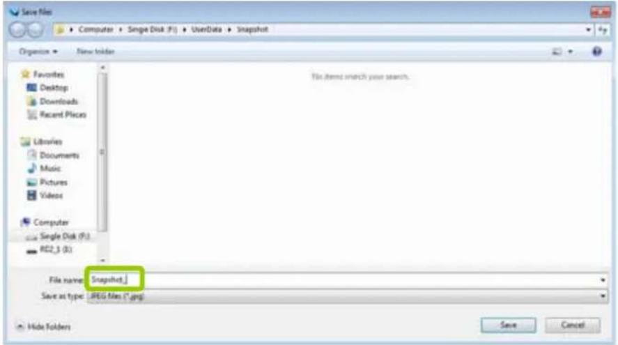
Taking a Snapshot
Please follow the steps below to take a snapshot of the live video stream:
a. Select a video cell from which you want to take a snapshot.
b. Click Snapshot 📷 on the quick access bar, or right-click the video cell and select Others > Snapshot from the popup menu. You also can click Edit > Snapshot to take a snapshot.
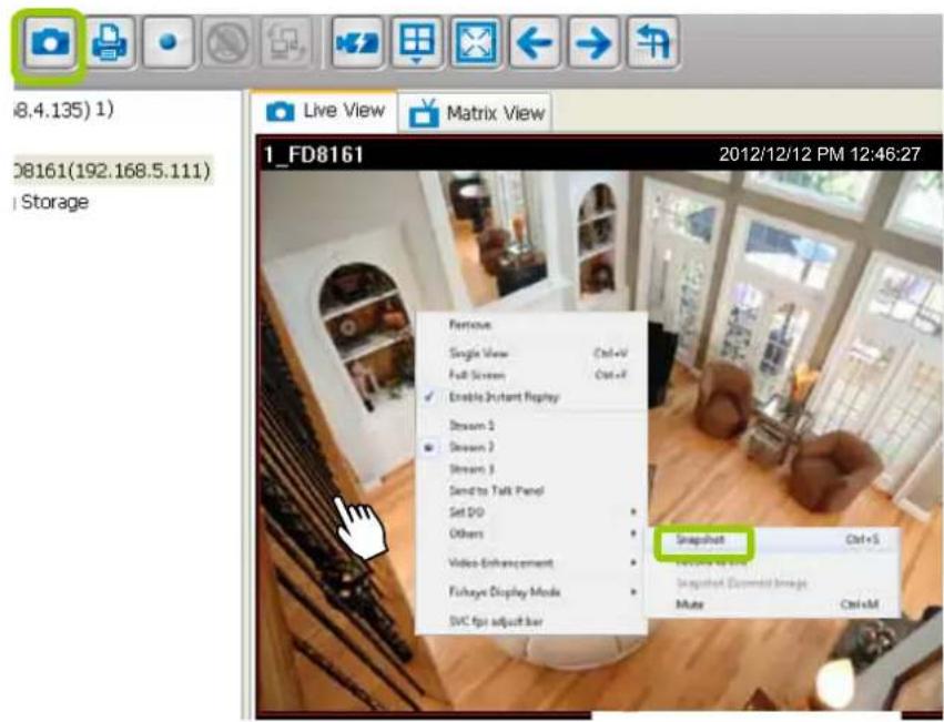
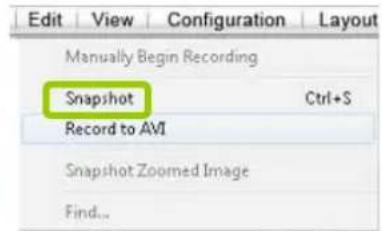
c. The snapshots will be found in the preset storage folder on your local computer.
Recording Settings
The VAST Server allows you to record the live video in EXE, 3GP, or AVI format to your storage folder.
Type 1: Record to EXE
Record video as an EXE file. The EXE is not only a media file but also a built-in media player. When user execute the EXE, the media file will be played automatically. There is no need to install any other program. For more information about how to use the EXE player, please refer to page 131.
Please follow the steps below to configure EXE record settings:
a. Click Configuration > Client Settings > Recording Settings on the menu bar to open the Recording Settings window.
b. Select EXE as the Record Type. The default storage path is E:\UserData\Record.
c. Select the Length of each file-- Maximum Size (10\~2000MB) or Maximum Time Interval (1\~150 min).
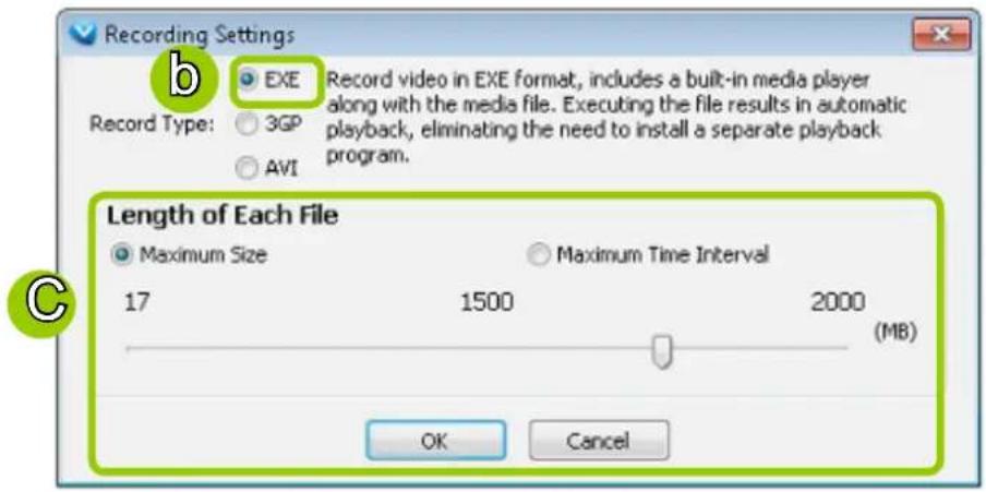
e. Click OK to enable the settings.
Type 2: Record to 3GP
Record video as a 3GP file. 3GP file is a standard MP4 format compatible with players such as VLC, QuickTime, or Real players. Choose this type if you has already installed one of these players.
Please follow the steps below to configure 3GP record settings:
a. Click Configuration > Client Settings > Recording Settings on the menu bar to open the Recording Settings window.
b. Select 3GP as the Record Type.
c. Select the Length of each file-- Maximum Size (1\~2000MB) or Maximum Time Interval (1\~150 min).
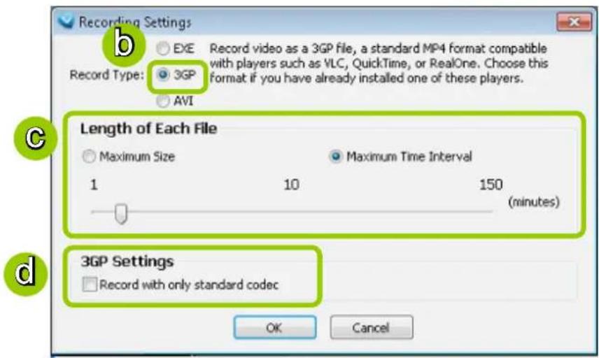
d. If you check "Record with only standard codec", the video from old models (VIVOTEK 6000-series products) using H.263 codec will not be recorded.
f. Click OK to enable the settings.
Type 3: Record to AVI
Record video as an AVI file, which uses the popular codecs pre-installed in the Windows OS. Please note that the speed may be slower due to the need of decoding the video/audio and re-encoding both into a compatible codec.
Please follow the steps below to configure AVI record settings:
a. Click Configuration > Client Settings > Recording Settings on the menu bar to open the Recording Settings window.
b. Select AVI as the Record Type.
c. Select the Length of each file-- Maximum Size (1\~2000MB) or Maximum Time Interval (1\~150 min).
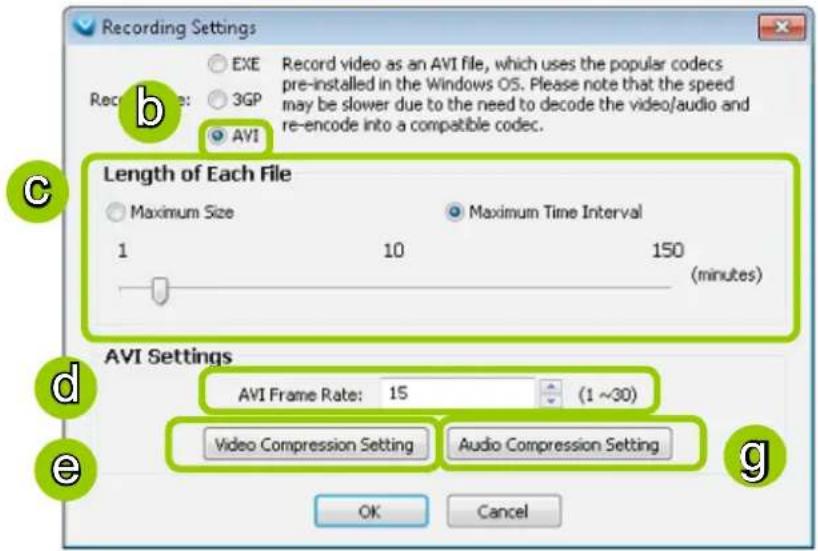

NOTE:
Because the AVI file has a limitation on the maximum file size of 2GigaBytes, if the setting "time length" generates data larger than 2G bytes, several files will be created.
d. Select the frame rate/ per second.
e. To modify the video compression settings, click Video Compression Setting to open the AVI Video Compression Setting window. Select the desired video compression algorithm, compression quality, key frame intervals, and data rate in the corresponding fields.
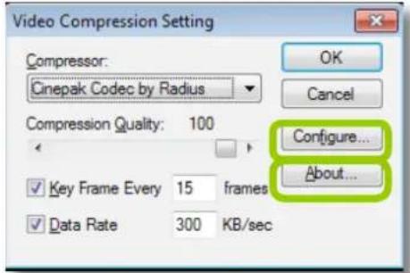

IMPORTANT:
If you do not choose to compress the video, the generated AVI file will be very large.
■ To modify the settings of the compression algorithm: Click Configure, then a dialog box will pop up for you to modify the settings. The dialog box will be different according to the compressor you select.
■ To read the information of a compression algorithm (its version for instance): Click About, and a dialog box will pop up showing the related information. The dialog box will be different according to the compressor you select.
f. To modify the audio compression settings, click Audio Compression Setting to open the AVI Audio Compression Setting window. Select the desired audio quality, format, and attributes in the corresponding fields.
![Audio Compression Setting Name: [untitled] Save As... Remove Format: PCM Attributes: 44.100 kHz, 16 Bit, Stereo 172 kb/sec OK Cancel](/content/2026/06/1279498/images/f7b2ac04eabce014c02e4a985ac71019b41451a07bdb604699675241b7560f28.jpg)
Record an EXE/3GP/AVI File
Please follow the steps below to record an EXE/3GP/AVI file of a live video stream:
a. Select a video cell or a device from the heirarchical management tree which you want to record to media file.
b. Click Record to EXE/3GP/AVI on the quick access bar, or right-click the video cell and click Record to EXE/3GP/AVI. You can also click Edit > Record to EXE/3GP/AVI on the menu bar. (The UI string will change according to your Recording Settings.)
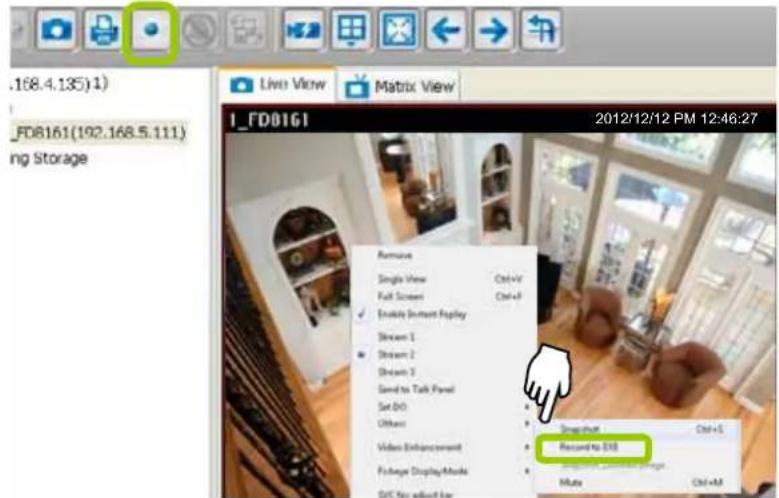
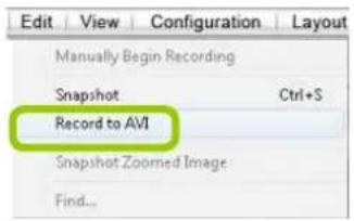
c. For recording a high-resolution video (1600 x 1200) in AVI type, a dialog box will pop up as shown below to remind you that the CPU loading will increase. Click OK to continue the process.
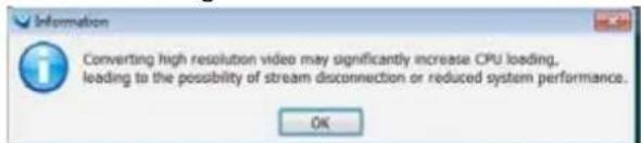
d. The icon will then change to Recording EXE/3GP/AVI, and a red text string (EXE/3GP/AVI) will appear at the bottom right of the video cell. Note that only one video channel can be recorded at a time.
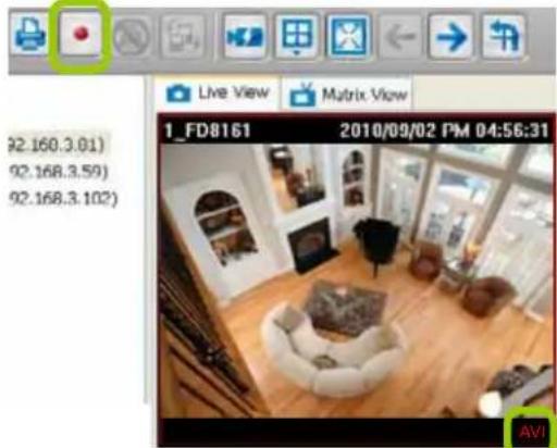

NOTE:
If you save your video via a LiveClient installed on another computer, the videos will be placed in where you installed the LiveClient utility: e.g., C::||VAST|Client|LiveClient|Record.
e. When you want to terminate the AVI Recording, click the icon ☐ on the Quick Access Bar. The export process will then terminate and the button will change from ☐ to ☐. The recorded media files will be found in the preset storage folder on your local computer as shown below.
Below is the file name format for AVI files:
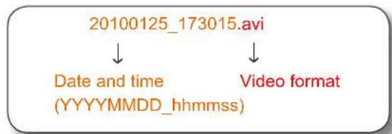
flowchart
graph TD
    A["20100125_173015.avi"] --> B["Date and time (YYYYMMDD_hhmmss)"]
    A --> C["Video format"]

20091118_112743.exe MediaPlayer Application

20091118_200608.avi 視訊短片 1,191 KB

20091118_195800.3gp 3GPP Movie 238 KB
Built-in Media Player--EXE
Below is the icon of footages saved as EXE files. Double-click on it, the recorded video will be played automatically as shown below. If you installed LiveClient on your PC, you may also open the built-in Media Player (VMSMediaPlayer.exe) in the default location: C:\Program Files (x86)\VIVOTEK Inc\VAST\Client\LiveClient.
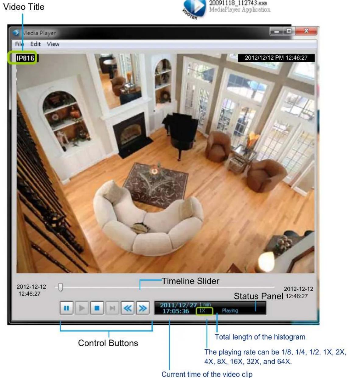
| Icon Function Description | |
| Pause Pause playback of the focused video clip | |
| Play Start playback of the focused video clip | |
| Stop Stop playback of the focused video clip | |
| Next Frame Go to the next video frame of the focused video clip | |
| Slow Down Slow down the playback rate | |
| Speed Up Speed up the playback rate | |
The function menu of the built-in media player are displayed as shown below:
| File Edit View | Edit View | View |
| Open 3GP File ... | Snapshot (BMP) | Full Screen |
| Save as EXE ... | Snapshot (JPEG) | |
| Save as 3GP File ... | Convert to AVI | |
| Exit |
■ The built-in player is able to playback 3GP files.
■ The built-in player is able to save 3GP files as EXE files.
■ The built-in player is able to save EXE files as 3GP files.
■ The built-in player is able to convert EXE and 3GP files into AVI files.
■ The built-in player also supports snapshot and print functions.

Tips
Below are special notices related to video recording with the fisheye cameras:
■ For recorded videos from the fisheye cameras, only the built-in Media Player can playback the Regional or Panoramic views. If you access the recorded videos using other playback software, you will end up with the circular-shape Original view.
■ When recording videos from fisheye cameras, the Regional and Panoramic views can only be preserved in the EXE and 3GP format. If you save the dewarped views, i.e., Regional and Panoramic, as AVIs, only the circular-shape Original view will be preserved.
■ Currently the video playback on the E-map window displays the Original view only.
■ To display a Regional or Panoramic view, right-click on the embedded Media Player window.
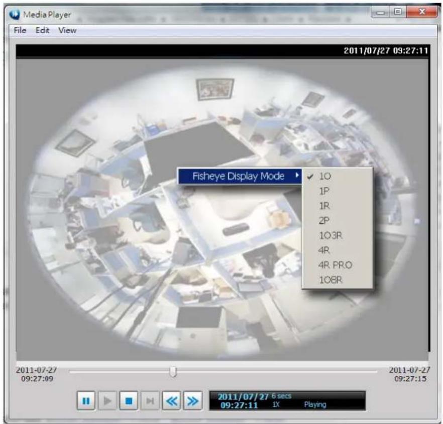
View Settings
This section allows you to set the display mode of a video cell, including Display Location, Date and time Format, Video Display Mode, and Font Settings. When you change the settings, the sample window will change accordingly for you to preview the settings.
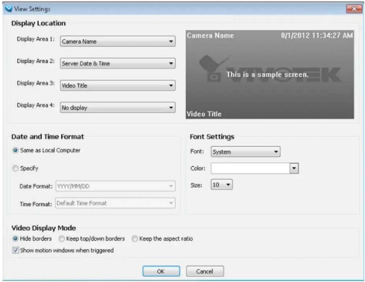
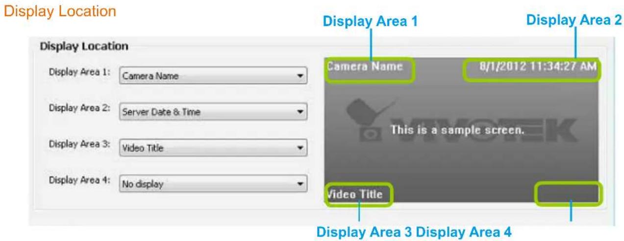
As the illustration shows, there are 4 display areas for you to input information about the live video. Each drop-down list includes 6 options for you to select: No display, Camera Name, Video Title, Camera Date, Camera Time, and Camera DateTime.
Date and Time Format
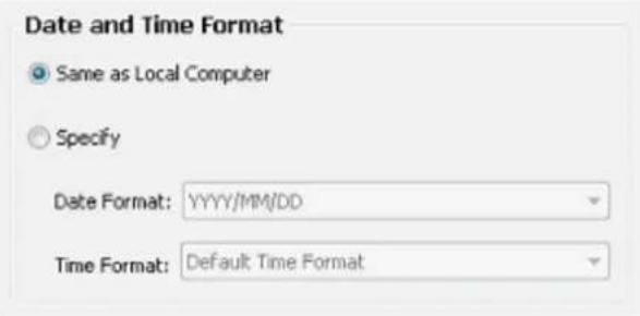
■ Same as local computer: Select this option and then the date and time format will synchronize with the local computer.
■ Specify: Select a desired format for the date and time from the drop-down list.
Date format: Select YYYY/MM/DD or MM/DD/YY.
Time format: Select the default time format (synchronize with the local computer), 12h AM/PM, or 24h.
Video Display Mode
Video Display Mode
Hide borders
Keep top/down borders
Keep the aspect ratio

Show motion windows when triggered
- Keep the aspect ratio: In the default settings, the size of the video window will change according to the layout of the live view window you choose. However, the frame size may be distorted. If you select Keep the aspect ratio, the video window will be adjusted to the same frame size as the preview window. This function is disabled as default.
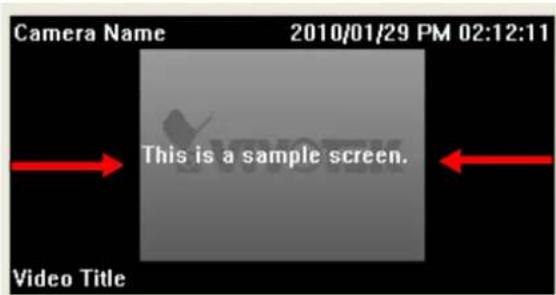
■ Hide borders / Keep top/down borders: Select if you want to change the view cell borders. Black information banners will appear if you keep the top/down borders.
■ Show motion window when triggered: If you select this option, the red frame of the motion detection window will appear in the video window when motion is triggered. This function is enabled as default.
For detailed information about how to set up the layout of the live view window, please refer to How to Change Video Viewing Mode on page 60.
Font Settings
Font Settings
Font:

Color:

Size:

This function allows you to change the font on the video cell.
■ Font: Automatically lists all fonts installed on your operating system. Select the desired type.
■ Color: Select a desired font color (white, red, green, blue).
■ Size: Select a desired font size (8, 10, 12, 14).
General Settings
This section allows you to configure the System Settings and Rotation Settings.
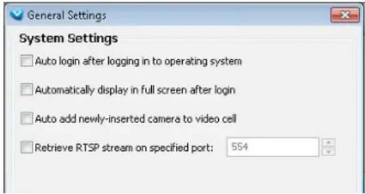
System Settings
■ Auto login after logging in to operating system: If you check this option, VAST LiveClient will automatically login after you login to Windows without filling in the user name and password. This function is disabled as default.
■ Automatically display in full screen after login: If you check this option, the video cells will be displayed in full screen without showing the menu bar or the control panels.
■ Auto add newly-inserted camera to video cell: If you check this option, VAST LiveClient will automatically add the newly-inserted device to a video cell. This function is enabled as default.
- Retrieve RTSP streaming on specific port: The default port for RTSP streaming is 554. If you want to change this port, please check this item and fill in a desired port.
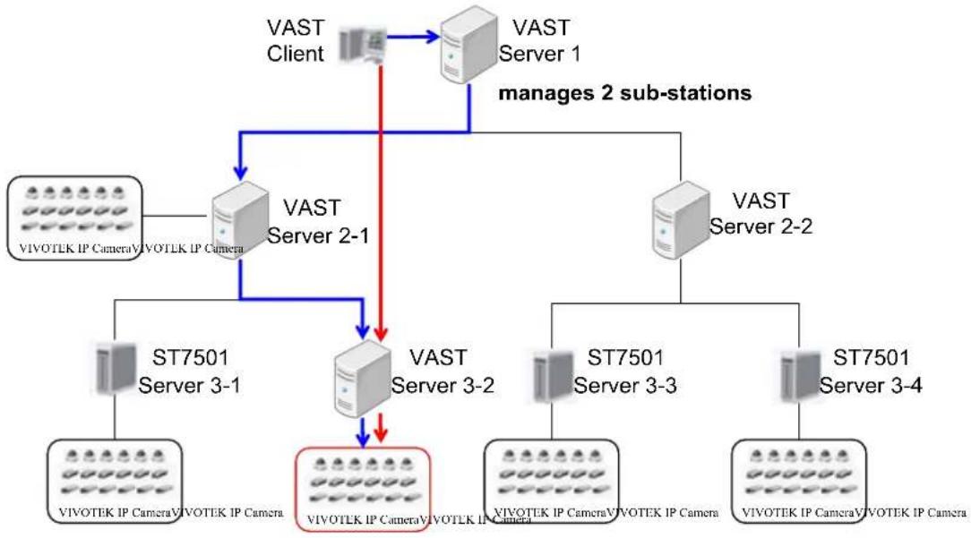
flowchart
graph TD
    A["VAST Client"] --> B["VAST Server 1"]
    B --> C["VAST Server 2-1"]
    C --> D["ST7501 Server 3-1"]
    C --> E["VIVOTLK IP Camera VIVOTLK IP Camera"]
    C --> F["VAST Server 3-2"]
    F --> G["VIVOTLK IP Camera VIVOTLK IP Camera"]
    F --> H["VAST Server 3-3"]
    H --> I["ST7501 Server 3-4"]
    H --> J["VIVOTLK IP Camera VIVOTLK IP Camera"]
    B --> K["VAST Server 2"]
    K --> L["VIVOTEK IP Camera VIVOTEK IP Camera"]
    style A fill:#f9f,stroke:#333
    style B fill:#ccf,stroke:#333
    style C fill:#cfc,stroke:#333
    style D fill:#fcc,stroke:#333
    style E fill:#cff,stroke:#333
    style F fill:#ffc,stroke:#333
    style H fill:#fcc,stroke:#333
    style I fill:#fcc,stroke:#333
    style J fill:#fcc,stroke:#333

NOTE:
■ If the VAST Server 3-2 is set up behind a firewall, the VAST Client will not be able to access the VAST Server 3-2 directly. You have to get the connection by relaying.
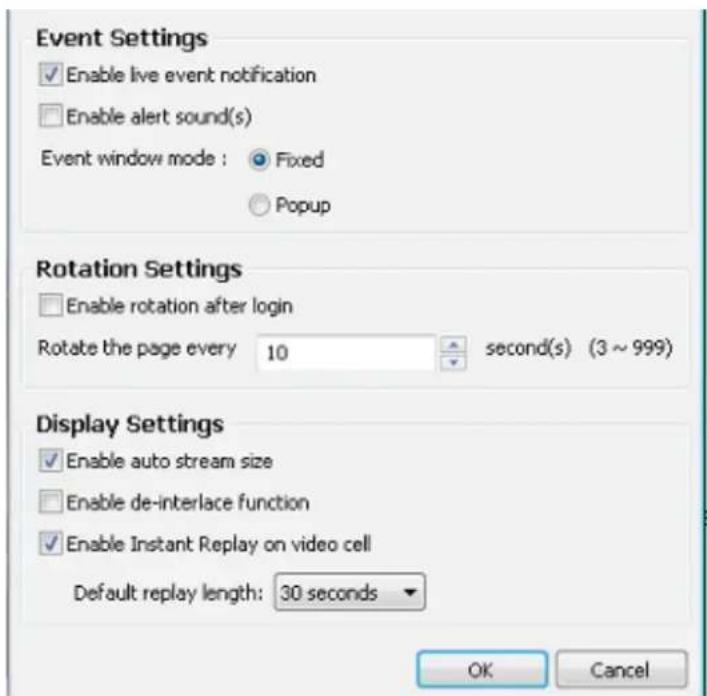
Event Settings
■ Enable live event notification: Select this option to activate real-time event notification. For example: the event notification of DI/O status on the hierarchical management tree, the event list in the event window, motion detection windows in video window, or the event notification on E-map settings page, etc. This function is enabled as default.
■ Enable alert sound(s): If you enable this option, you will hear alert sound on the client side when the event is triggered..
■ Event window mode: Select Fixed or Popup mode for the event window. For more information about event window, please refer to page 33.
Rotation Settings
■ Enable rotation after login: If you check this option, the video cells will start to rotate after you login to the VAST LiveClient. The default setting of this function is disabled.
■ Rotate the page every second(s): Fill in a desire interval time for video page rotation. The maximum value is 99 seconds. The default value is set at 6 seconds.
For detailed information about how to set up the layout of the monitoring window and rotation functions, please refer to How to Change Video Viewing Mode on page 60.
Display Settings

WARNING:
Please do not disable the Auto stream size option. Disabling Auto stream size can cause a performance problem with the system. Today's megapixel cameras produce high resolution videos that, if not properly processed, can overstress the system.
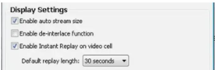
■ Enable auto stream size: The Auto Stream Size feature dynamically adjusts the stream sizes of video feeds from network cameras in order to reduce CPU load and bandwidth consumption.
It is often the case that in surveillance deployments the physical dimensions of monitors, the effectiveness of visual stimulus, and the operators' regions of interest can all be very limited. Streaming large-size videos at all times will be a waste of bandwidth and system computing power. CIF and VGA size videos are usually sufficient for the operators of a surveillance software.
When enabled, your LiveClient station automatically requests smaller-size streams as video feeds from the network cameras.
When the size of view cells is manually expanded, a VAST server requests a different larger stream.
Facts about Auto Stream Size:
- The LiveClient utility automatically adjusts stream selection according to the size of view cells, no user's configuration is required.
- The frame size of stream #1 is user-configurable.
- Under no circumstances should you disable the Auto Stream Size function.
- Stream jump takes place on the display of all connected cameras once the function is enabled.
- If users configured a region of interest before the Auto Stream Size function is applied, e.g., via the ePTZ control, the view cell might display a different live view.
■ Enable de-interlace function: Select this option if your connected device does not support de-interlace function. For example: VS7100.
■ Enable Instant Replay on video cell (on a LiveClient installed to a PC): When enabled, a small Replay icon will be available on each view cell. One pre-condition is that the video stream must be currently being recorded to the NVR sysm.
Default replay length: Default is 30 seconds, use the pull-down menu to select a different length for video playback.

NOTE:
Instant Playback should be performed on one view cell only. If you playback multiple 1080P recording streams simultaneously, you may encounter system faults.

Instant Playback
Return to Live
To initiate an instant playback, move your mouse cursor to the lower left corner of a live cell. The Instant Playback icon will appear. Click on it, and a progress bar will appear. Click on the Play button to playback a configurable length of video that was recorded just before you started the Playback function (default is 30 seconds).
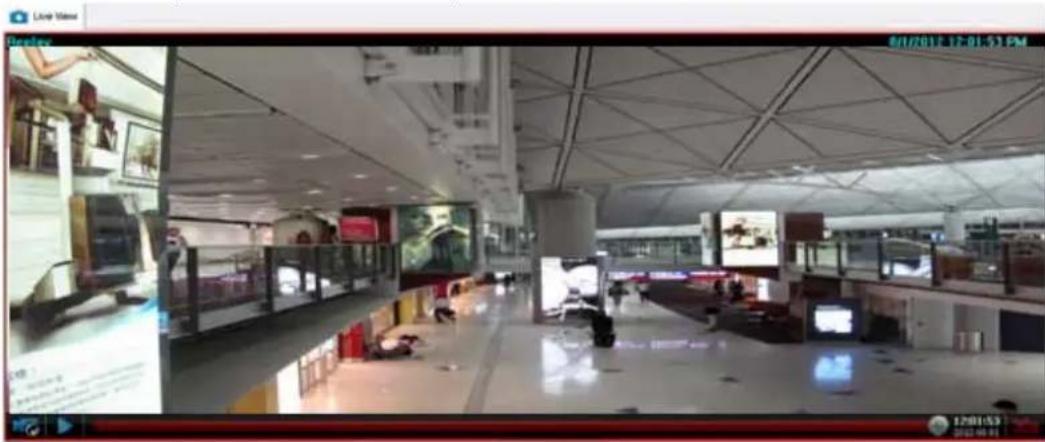
Joystick Settings
This section explains how to remotely control the network cameras using a USB joystick.
Enable Joystick
Connect to the USB plug of the joystick to a USB port on your computer. Supported by the plug-in in the main page (Microsoft's DirectX), once the plug-in in the main page is loaded, it will automatically detect if there is any joystick on the computer. The joystick should work properly without installing any other driver or software.
Then you can begin to configure the joystick settings of connected devices. Please follow the instruction below to enable joystick settings.
a. Select the target device from the hierarchical management tree.
b. Click Configuration > Client Settings > Joystick Settings on the menu bar to open the Joystick Settings window. If your joystick is working properly, it will be displayed on the drop-down list.
c. Select the joystick you want to configure. Check Enable Joystick, then click Configure Buttons to open Buttons configuration window.
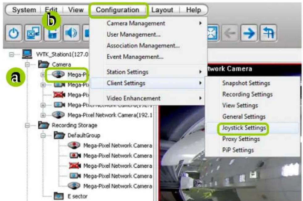
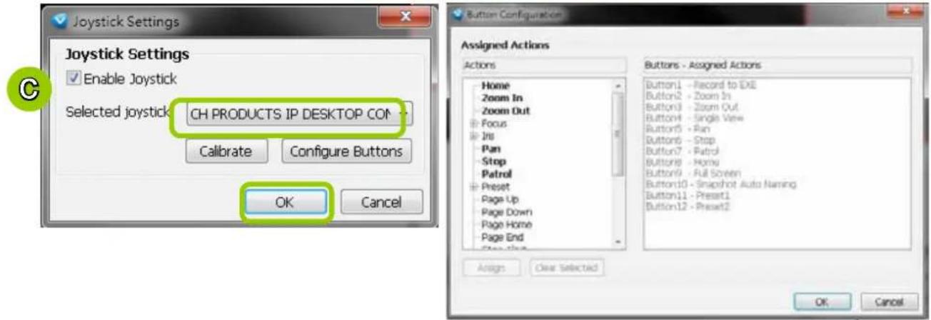
Buttons Configuration
In Button Configuration window, the left column shows the actions you can assign, and the right column shows the functional buttons and assigned actions. The number of buttons may differ from different joysticks.
Please follow the steps below to configure your joystick buttons:
a. Choosing one of the actions and click Assign will pop up a dialog. Then you can assign this action to a button by pressing the joystick button or select it from the drop-down list.
For example: Assign Home (move to home position) to Button 1.
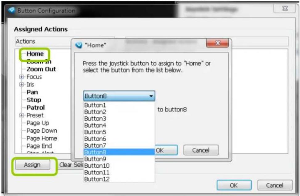
b. Click OK to confirm the configuration.
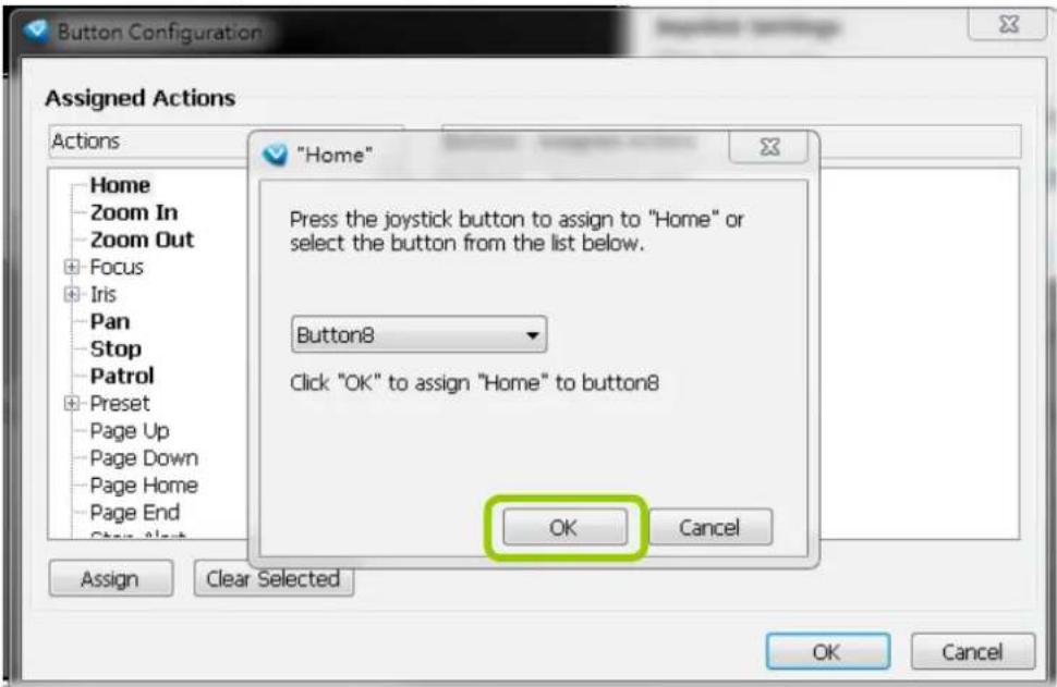
c. The Assigned Action will appear beside Button 1 in the right column as shown in the following diagram. Note that a button can only be assigned with an action. If you want to modify the settings, select the action on the list and click Clear Selected.
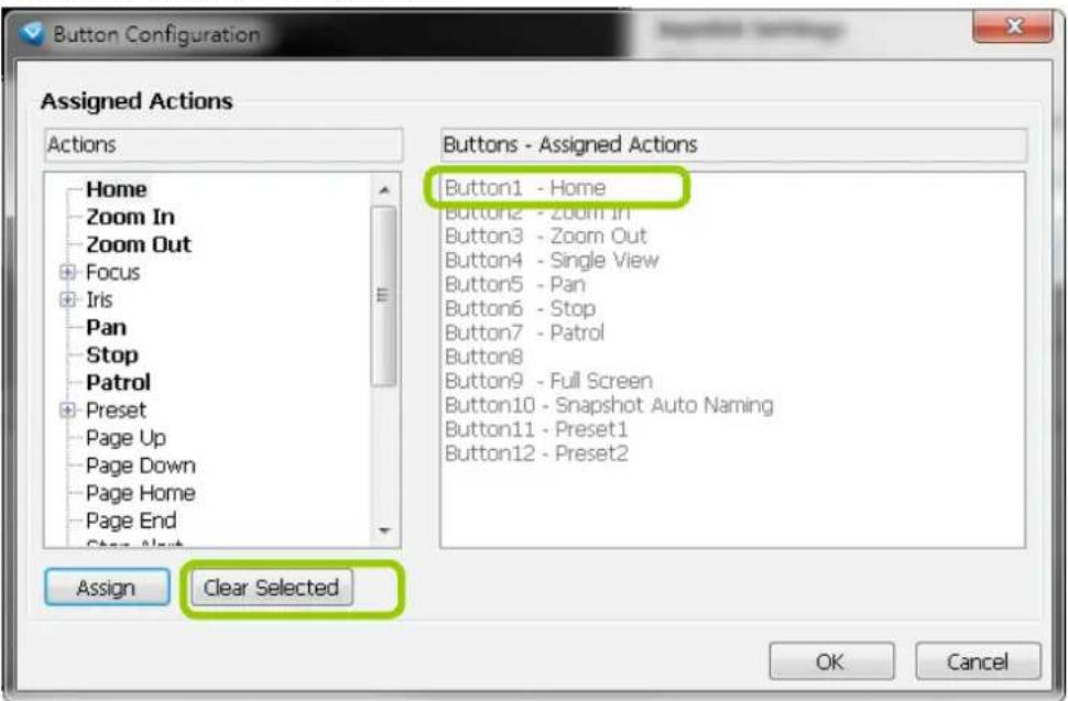
d. If you want to assign additional actions, repeat step a.\~c. When all settings are complete, click OK to save the settings or click Cancel to discard the settings.
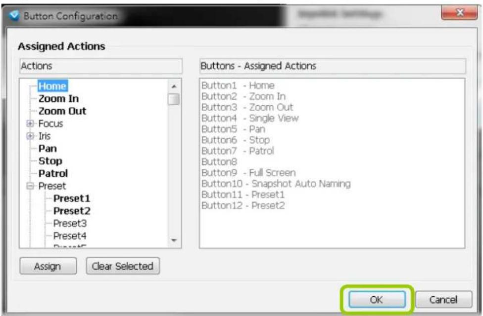
e. Click OK to save the settings or click Cancel to discard the settings.
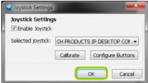

NOTE:
■ If you want to assign Preset actions to your joystick, the preset locations should be set up in advance.
■ If your joystick is not working properly, it may need to be calibrated. Click Calibrate to open the Game Controllers window located in the MS Windows control panel and follow the instructions for trouble shooting. For more information, please refer to the MS Windows help files for details.
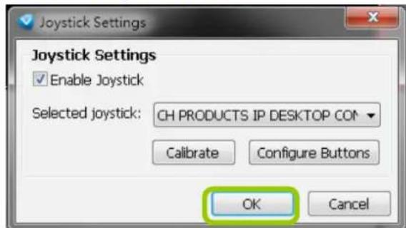
■ The joystick will appear in the Game Controllers list in the Windows Control Panel on your computer. If you want to check out your device, go to the following page: Open Start > Control Panel > Game Controllers.
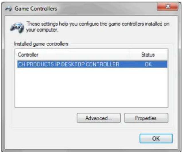
PTZ/ E-PTZ Function
In addition to using the PTZ control panel, you may also control the rotation handle on the joystick with ease.
Pan/Tilt: Move the rotation handle of the joystick; you can pan the camera to the desire position. There will be blue line displaying the moving direction in the center of the video image as the diagram 1 below.
Zoom in/Zoom out: Shift the rotation handle clockwise to zoom in the camera on an image or go counterclockwise to zoom out the camera on an image. There will be a circle and four vectors in the center of the video image as the diagram 2, 3 below.
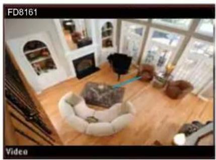
natural_image
Interior view of a modern living room with white furniture, large windows, and a wooden floor (no visible text or symbols)Pan/Tilt
(Move the rotating handle back and forth)
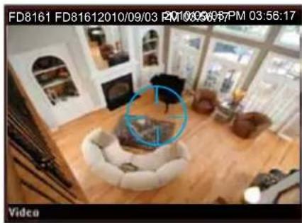
Zoom in
(Turn the rotating handle clockwise)
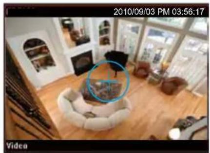
natural_image
Interior view of a modern living room with sofa, coffee table, and large windows (no visible text or symbols)Zoom out
(Turn the rotating handle counter-clockwise)
Proxy Settings
If you are not running the LiveClient on a remote computer, skip the below description. In this section, you can enable, modify, or cancel Proxy Settings for client if your VAST Server is under a proxy. If you change the proxy settings, please fill in the new value next time you login the LiveClient next time.
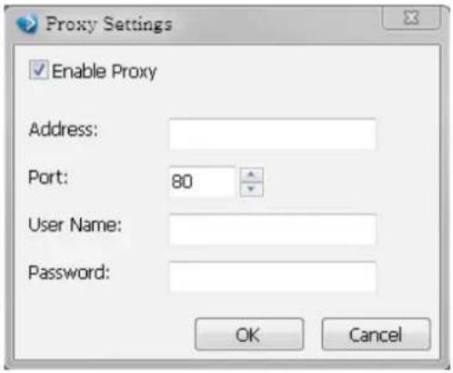
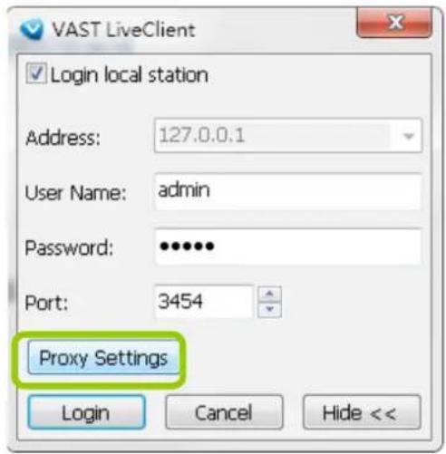
How to Use PiP (Picture-in-Picture)
PiP (Picture-in-Picture) is an intuitive function for user to simultaneously view a Global View and ROI (Region of Interest) for live monitoring. The digital zoom in function can only focus on the interested area and represent the details of megapixel video. Moreover, the multi-touch mode is a very user-friendly interface for digital zoom in.
Enable PiP
Right-click the video cell and select Enable PiP. If you want to disable PiP, click the option again to uncheck it. After you enable the PiP function, a movable global view window and a ROI frame will be displayed as shown below.
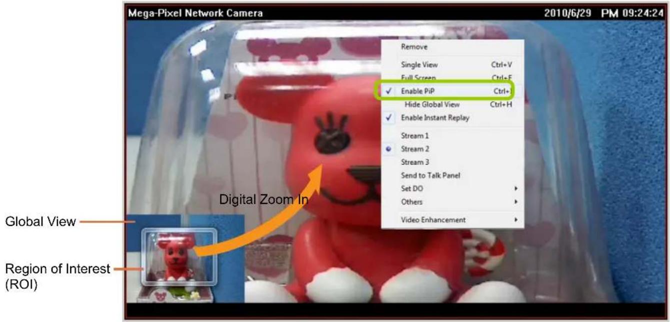
Global View
The global view is the original view with the size scaled down to 160x120. It is movable and you can drag it anywhere across the live view window. If you want to hide the global view, right-click the video cell and select Hide Global View from the menu. A magnifier icon will appear on top of the live view window.
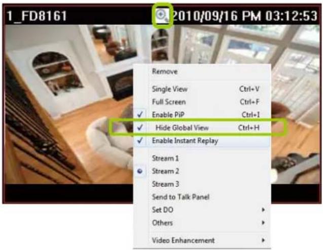
ROI (Region of Interest)
The ROI frame can be resized and moved in any direction across the global view window. The working theory is similar to the e-PTZ function.
Digital Zoom In
Through digital zoom in, the live view window will be filled with the zoomed in ROI image. The maximum magnification of the ROI frame is 16x zooming. The zoomed in area will change as the ROI frame is dragged and resized. You can also easily zoom in and zoom out the ROI frame by rolling the mouse back and force.
Snapshot Zoomed In Image
You can snapshot a zoomed-in image.
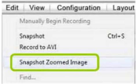
PiP Settings
The PiP Settings is for you to adjust the initial position of the global view window.
Click Configuration > Client Settings > PiP Settings to open the window. On top of it, you may choose the horizontal position with left / middle / right side of the live view window, or you can customize the percentage of space distance from the border of the live view window as an option. It is also fully applied for vertical position with top / middle / bottom side of the live view window. When it's done, you may click on Apply to existing windows to enable the settings.
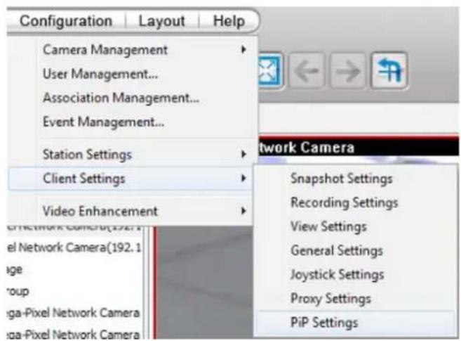
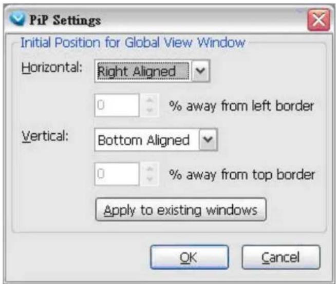

NOTE:
■ The ROI and global view position will be removed when the live view cell is removed from the main screen.
■ The PiP function also applies in the Playback utility.
How to Configure Video Enhancement

IMPORTANT:
The Video Enhancement function consumes considerable system resources. It is not recommended to exert this function on multiple view cells.
The LiveClient allows you to enable post-image enhancement and defog for video live view.
Basic Image Adjustment
This function allows you to configure basic image adjustment including Brightness, Contrast, Saturation, and Hue.
Please follow the steps below to set a profile for post-image adjustment settings:
a. Select the target video cell.
b. Click Configuration > Video Enhancement > Basic Image Adjustment > Settings on the menu bar to open the Profile Settings window. (Or you can right-click the video cell and select Video Enhancement > Basic Image Adjustment > Settings from the popup menu.)
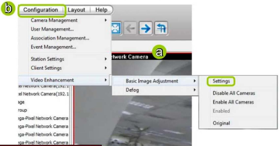
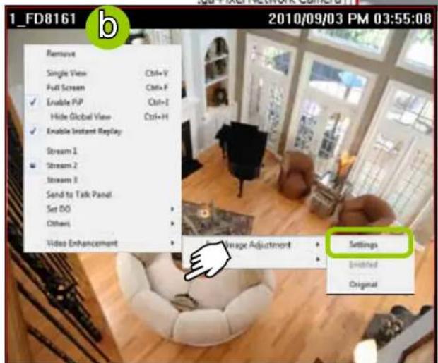
c. Adjust the values of Brightness, Contrast, Saturat-
tion, and Hue. You can preview the image from the
window on the right. A "VE (Video Enhancement)"
text string will appear at the bottom right of the
preview window.
d. When completed, click Save as Profile and enter a name for the new profile.
e. The new profile will be displayed on the drop-down list. This profile can be applied to all video cells.
f. If you decide to apply the selected profile to the target video cell immediately, click the OK button. Otherwise, click Cancel to close the window.
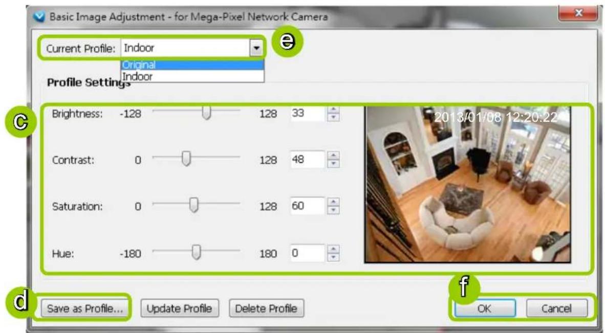
g. Back to the main page, a "VE" text string will also appear at the bottom right of the video cell and the new profile will also appear and be selected on the popup menu as shown below.
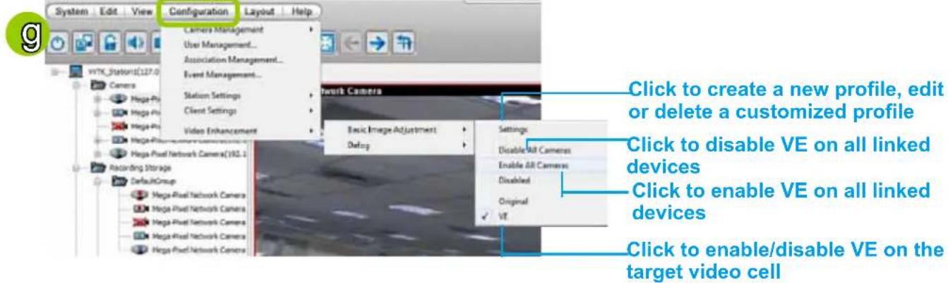
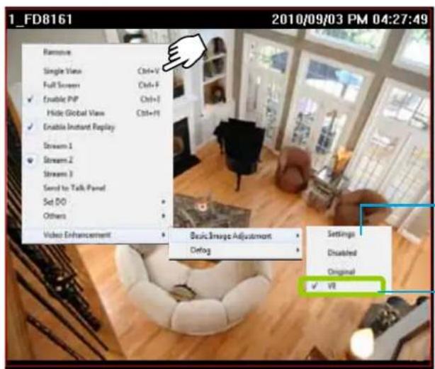
Click to create a new profile, edit or delete a profile
Click to enable/disable VE on the target video cell
Defog
This function allows you to configure post-image defog.
Apply a Preset Defog Profile
Please follow the steps below to set post-image defog settings:
a. Select the target video cell.
b. Click Configuration > Video Enhancement > Defog or right-click the video cell and select Video Enhancement > Defog.
c. There are some preset profiles for you to apply to the target video cell. You can select one from the list according to the environment.
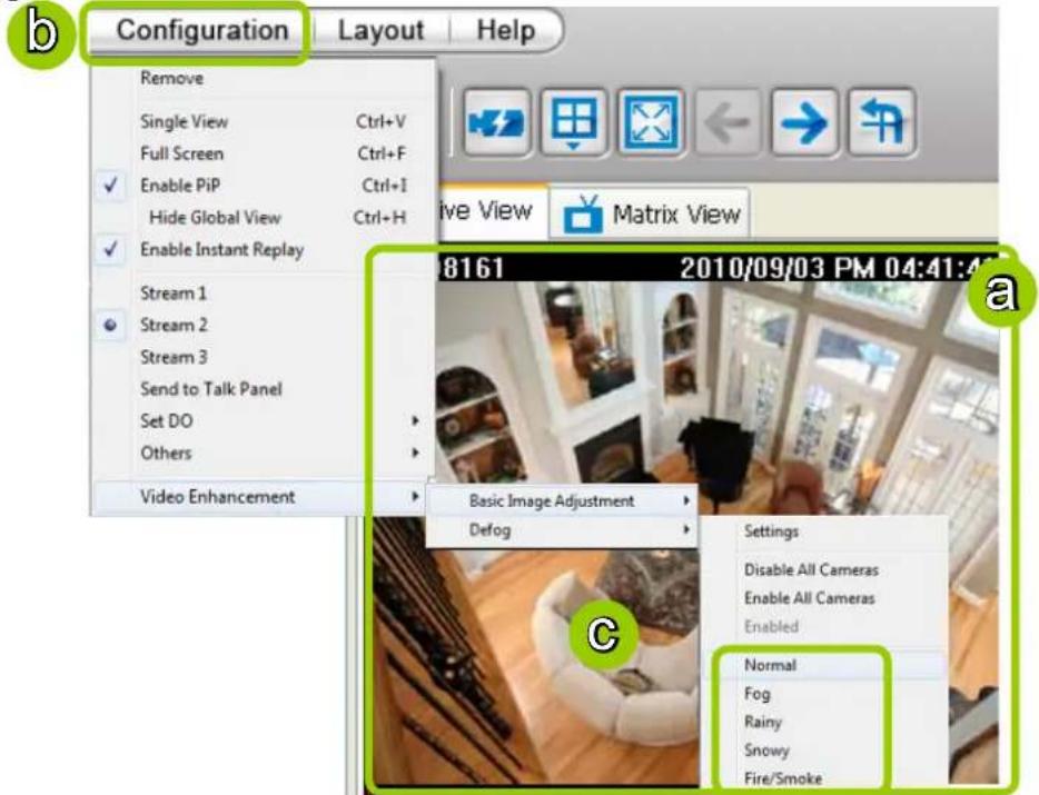
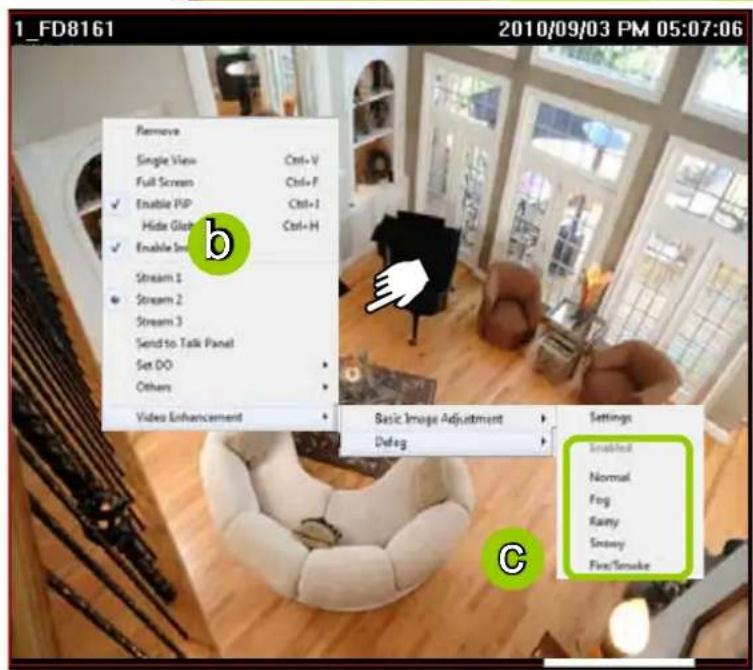
d. The string of the selected profile will be selected as shown below. A "VE" text string will also appear at the bottom right of the video cell.
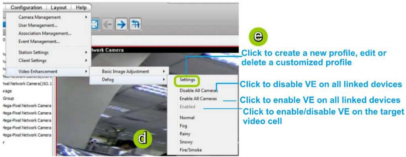
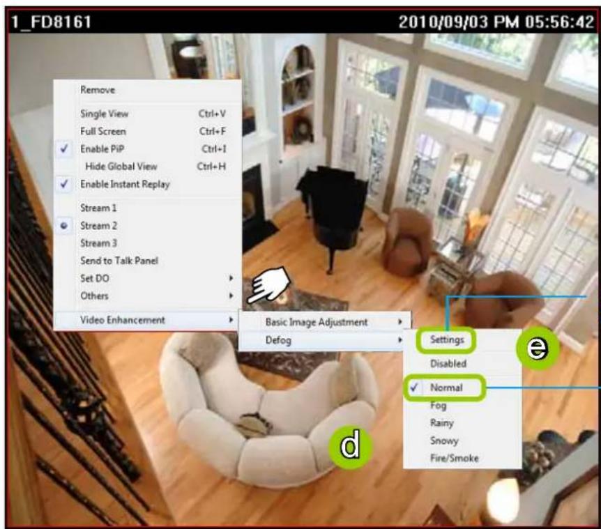
Click to create a new profile, edit or delete a profile
Click to enable/disable VE on the target video cell
Create a New Defog Profile
e. Click Settings on the popup menu to open the Profile Settings window.
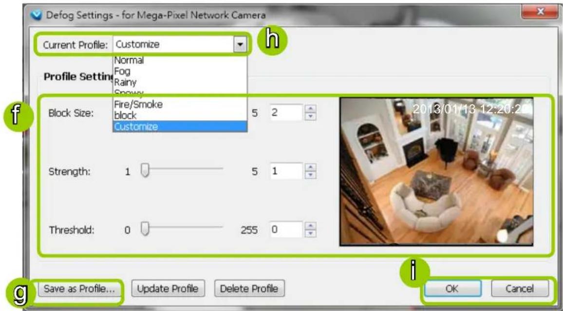
f. Adjust the values of Block Size, Strength, and Threshold. You can preview the image from the right window. A "VE (Video Enhancement)" text string will also appear at the bottom right of the preview window.
Block Size: Brush diameter from thick to thin (Value 1\~5)
Strength: Brush stroke from soft to strong (Value 1\~5)
Threshold: Brush pixel from loose to dense (Value 0\~225)
g. When completed, click Save as Profile and enter a name for the new profile.
h. The new profile will be displayed on the drop-down list. This profile can be applied to all video cells.
i. If you decide to apply the selected profile to the target video cell immediately, click the OK button. Otherwise, click Cancel to close the window.
How to Search for a Device on the Hierarchical Device Tree
This function allows you to conveniently search for an inserted device, which is useful when many devices have been inserted.
Please follow the steps below to find a device on the camera list:
a. Click the station on the hierarchical management tree.
b. Click Edit > Find on the menu bar (or right-click the station and click Find).
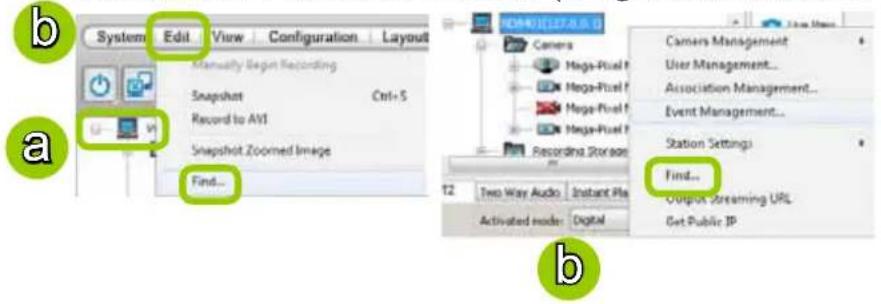
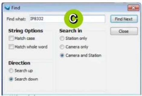
c. The Find window will pop up for you to set your search criteria.
■ Find what: Enter a string in the blank. The string can be the full or partial name of the device you want to search for.
■ String Options: Match case represents that the search results should be identical to the string in lower-case or upper-case letters, the string can be part of a word. Match whole word means that the search results should be identical to the string for every character, and that the string should be a complete word or phrase. If you select both options, the search results should conform to all criteria listed above.
■ Direction: Select search up or search down.
■ Search in: Select search in station or camera.
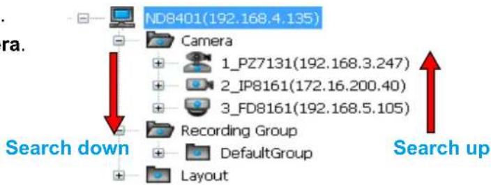
d. Click Find Next, the seaching result will be marked as shown below.
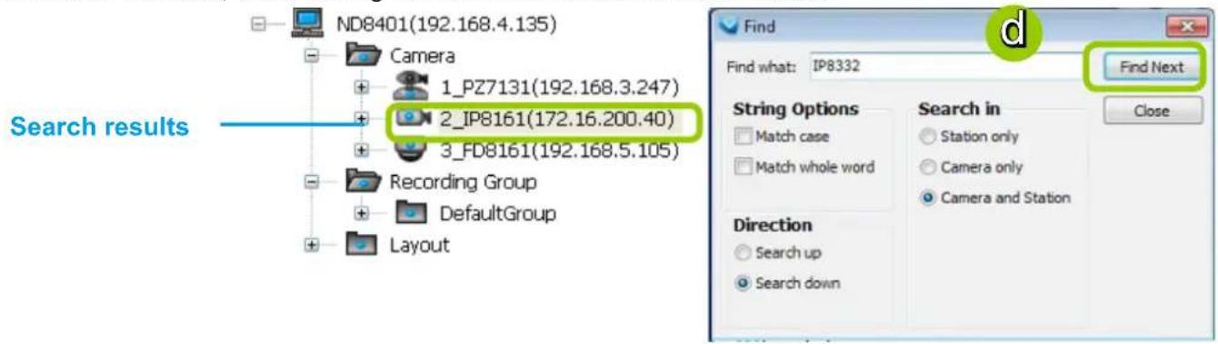
e. If there is nothing found in the camera list, a message will pop up as shown below:
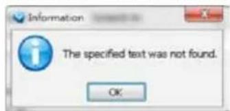
How to Lock LiveClient for Security Concerns
If you are away from your computer, for security reasons, we suggest you lock the program. When LiveClient is locked, the user must fill in the correct password to unlock and access the program again.
■ To lock LiveClient, click Unlock 🔒 on the quick access bar or click System > Lock on the system menu. The Unlock 🔒 icon will then turn into Lock 🔒
■ To unlock LiveClient, fill in the correct password in the popup window.
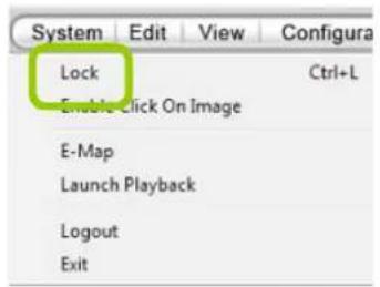
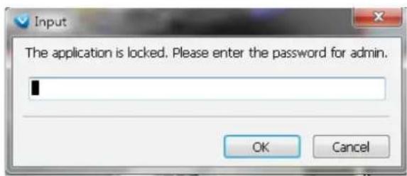
How to Log out from the VAST Server
To logout from the current server, click Logout 📋 on the quick access bar or click System > Logout on the menu bar. A confirmation window will pop up. Click OK to confirm or Cancel to return to the VAST LiveClient window.
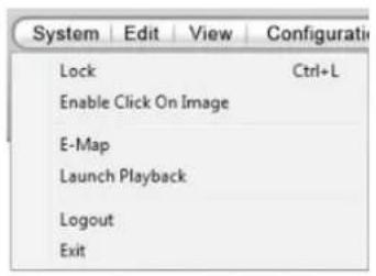
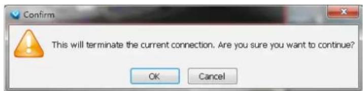
How to Exit VAST LiveClient
To exit VAST LiveClient, click Exit 🔒 on the quick access bar or click System > Exit on the menu bar. A confirmation window will pop up. Click OK to confirm or Cancel to return to the VAST LiveClient window. When you exit the program, your user account will be automatically logged out from the current server.
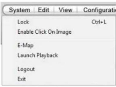
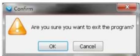
Lauch Playback
Click on Launch Playback to directly open the Playback utility.
| System | Edit | View | Configurati |
| Lock | Ctrl+L | ||
| Enable Click On Image | |||
| E-Map | |||
| Launch Playback | |||
| Logout | |||
| Exit | |||
Note that the LiveClient utility is still running in the background when you return to the Control Center.
Second View
This function is only available on a LiveClient running a PC that has 2 monitors. Clicking the button opens the second live view window enabling the display of more camera views.
Chapter Three NVR Playback Configuration
Activating VAST Playback and Logging in to a Server
VAST Playback allows you to search and playback recorded media data from the NVR system. Once you insert a device into the hierarchical device tree on the LiveClient, it is automatically listed on the device tree on the Playback utility. You can then begin to use Playback to view, retrieve, and search for recorded or backed-up video clips.
Please follow the steps below to activate the Playback utility:
- Run the Playback program. If you have already run the LiveClient, you can click on System > Launch Playback to open a Playback console.
- A Login window will prompt. Fill in the information as shown below:
■ By default, the Playback console automatically log in to the VAST Server running on the NVR system. Enter the User Name, Password, and Communication Port of the local server to log in. Click Login to log in to the target server or Cancel to exit the system.
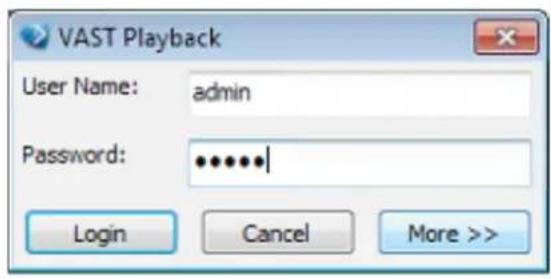
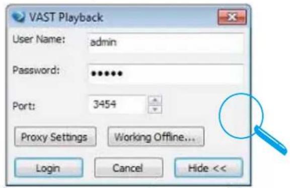
- The VAST Playback main window will be displayed.

NOTE:
■ If your network environment need to set up proxy, click More >> to extend the login window, then click Proxy Setting to open the dialog. Then enter related information to link to your proxy server.
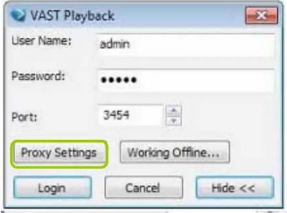
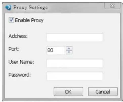
■ Available functions of the VAST Playback program will be enabled according to the role of your login account. For more details about the privileges of the user account, please refer to How to Manage User Accounts on page 57.
■ You may want to open the LiveClient and the Playback utilities simultaneously, use the Launch LiveClient command on the menu bar.
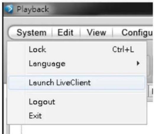
VAST Playback User Interface
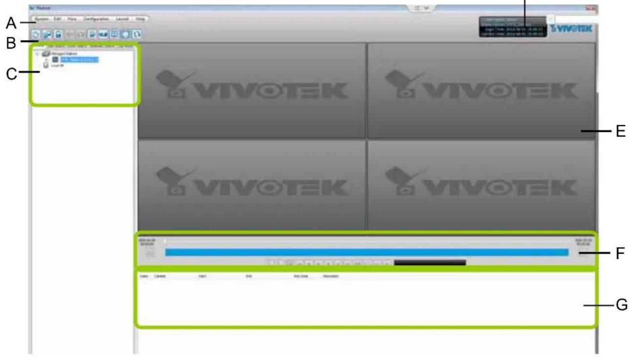
A. Menu bar
viewer)
G. Video clips list
B. Quick access bar
status panel
C. Query panel (Browsing / Time search /Event search / Log
E. Recorded video playback window
F. Playback control panel
Menu Bar
| Menu Item Drop-down Options | |
| System Lock / Language / Launch LiveClient / Logout / Exit | |
| Edit | Snapshot / Snapshot Zoomed Image / Print Zoomed Image / Find |
| View | Backup Status /Exporting Status / Time Search / Event Search / Bookmark Search / Log Viewer / Full Screen |
| Configuration | Client Settings (Snapshot Settings / Export Settings / View Settings / Proxy Settings / General Settings) /PiP Settings |
| Layout Change | Layout |
| Help About | |
Status Panel
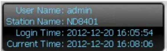
| User Name |
| Station Name (IP Address) |
| Login Time (yyyy-mm-dd hh:mm:ss) |
| Current Time (yyyy-mm-dd hh:mm:ss) |
Quick Access Bar

Icon Function Description

Exit Exit the system

Logout Logout from the current station

Lock Click to Lock the system for security concerns ( Unclock the system)

Volume Adjust the audio volume of the target video (

Snapshot Capture the picture of the target video

Print Print the current cell or the view of all cells

SVC Level Exert SVC control of video playback frame rate

Remove All Connection Remove all live videos from the live video monitoring window

Layout Change the layout of video monitoring window
Full Screen Maximize the live video monitoring window


NOTE:
Some buttons will be disabled if the selected device does not support those functions.
Recorded Video Playback Window
The "VIVOTEK" wallpaper is in place if no camera has been assigned to the video cell.
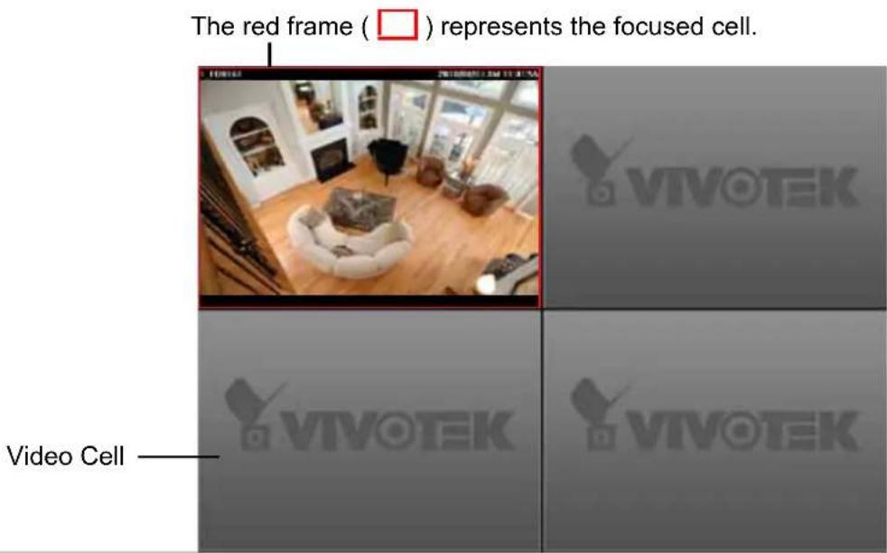
Query Panel-- Browsing Page
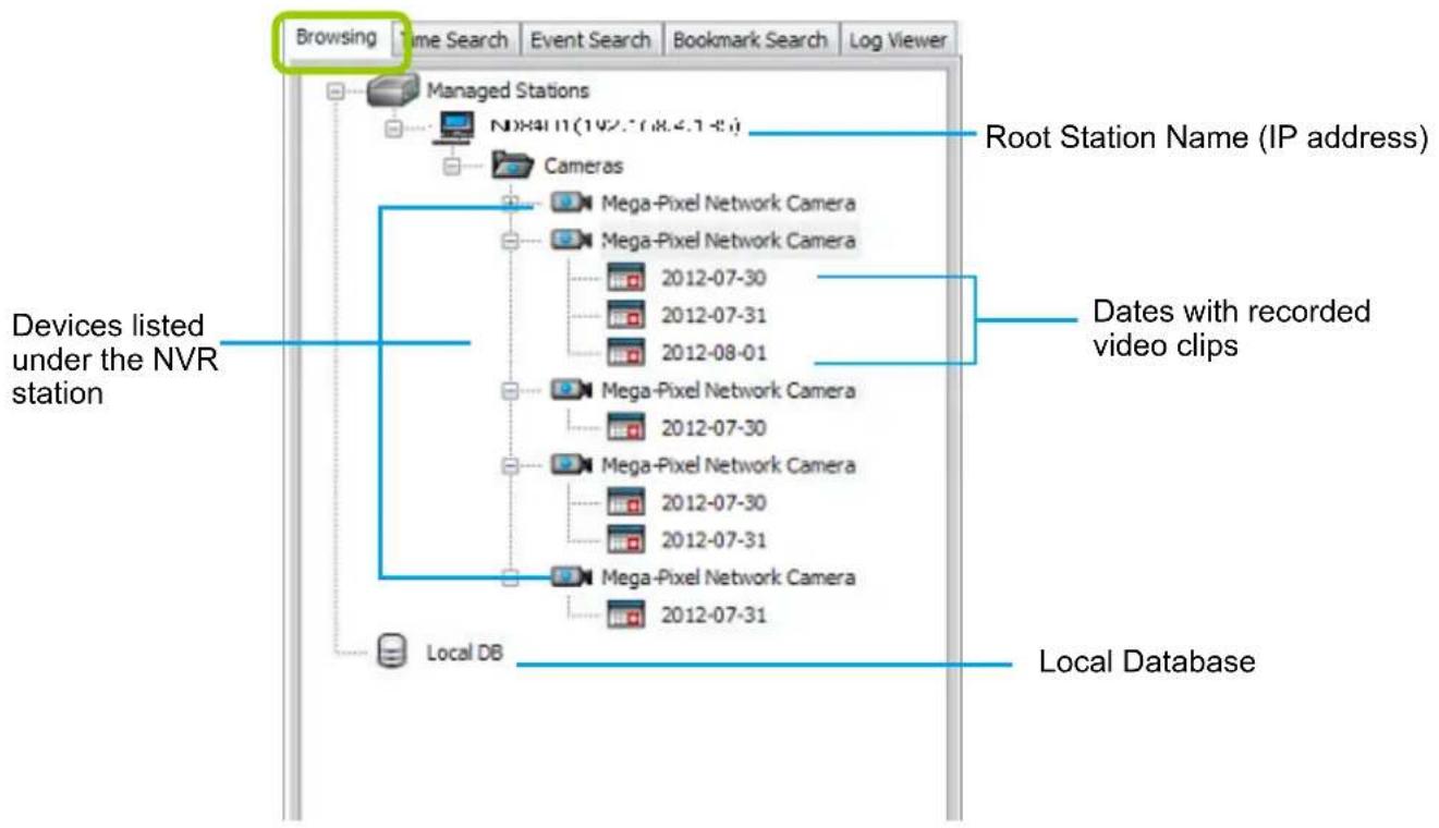
flowchart
graph TD
    A["Browsing"] --> B["Managed Stations"]
    B --> C["N08411(192.1708.4.1-8)"]
    B --> D["Cameras"]
    D --> E["Mega-Pixel Network Camera"]
    D --> F["Mega-Pixel Network Camera"]
    D --> G["2012-07-30"]
    D --> H["2012-07-31"]
    D --> I["2012-08-01"]
    E --> J["Mega-Pixel Network Camera"]
    E --> K["2012-07-30"]
    E --> L["Mega-Pixel Network Camera"]
    E --> M["2012-07-30"]
    E --> N["2012-07-31"]
    E --> O["Mega-Pixel Network Camera"]
    E --> P["2012-07-31"]
    Q["Devices listed under the NVR station"] --> R["Local DB"]
    S["Root Station Name (IP address)"] --> T["Dates with recorded video clips"]
    U["Local Database"] --> V["End"]
| Icon Description | |
| NVR Station list including server and local database | |
| A station (NVR that has a running VAST Server) | |
| The camera that exists on the hierarchical device tree of LiveClient. | |
| The camera that has been removed from the hierarchical device tree LiveClient (off-line). However, its recorded video (if any) is still accessible from the server. | |
| Dates with recorded video clips. | |
| Local database for backup data. For more information about how to upload backup data to the list, please refer to page 166. | |
Query Panel--Time Search Page
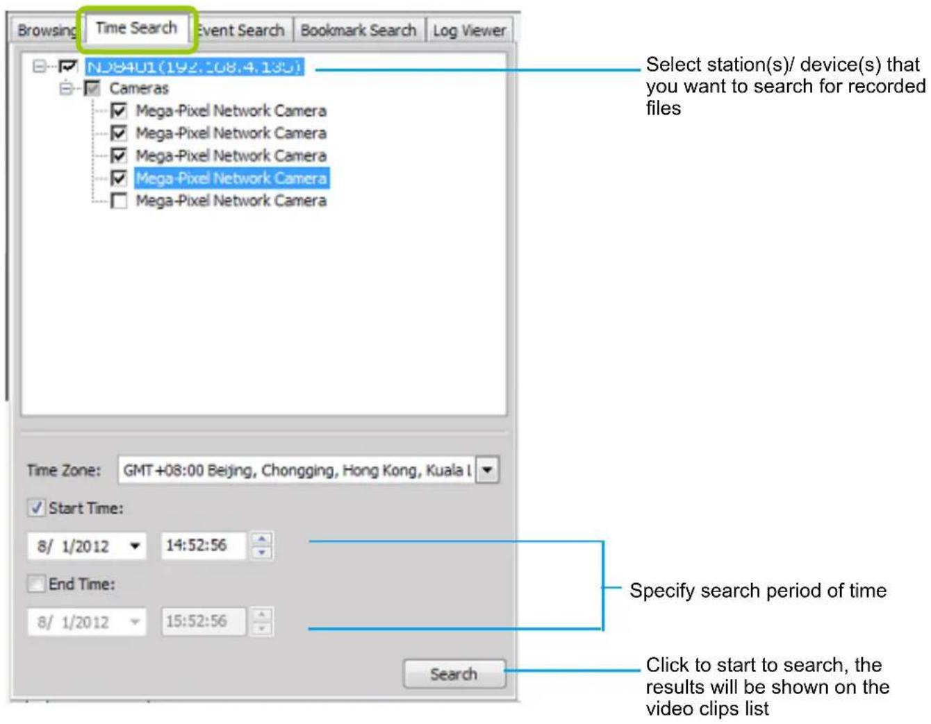

NOTE:
The Time Zone setting is automatically synchronized with that on the NVR station.
Audio Control

The audio function will be enabled if the device is equipped with an internal or external microphone. Please follow the steps below to adjust the volume or turn the audio on/off for a video stream:
■ To turn off the audio (Mute Mode)
a. Click Audio On 📋 on the quick access bar and check Mute. Or you can right-click on the video cell to open the popup menu, then click Others > Mute. The mute option in the popup menu will then be selected.
b. If you want to turn off the audio of all live video, select Apply all.
c. The Audio icon will then change from to
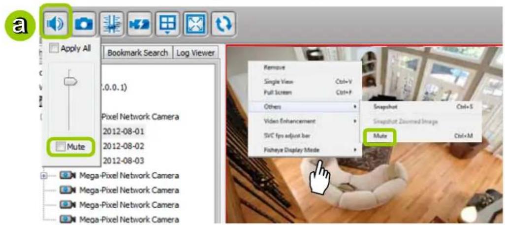
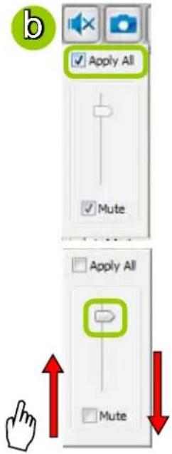
flowchart
graph TD
    A["Apply All"] --> B["Mute"]
    C["Apply All"] --> D["Mute"]
    style A fill:#f9f,stroke:#333
    style B fill:#ccf,stroke:#333
    style C fill:#cfc,stroke:#333
    style D fill:#fcc,stroke:#333
■ To adjust the audio volume
a. Click Audio On on the quick access bar.
b. Drag-and-drop the slider bar. Slide to a higher position for louder volume.
■ To turn on the audio
a. Click Mute 📋 on the quick access bar and uncheck Mute. Or you can right-click on the video cell to open the popup menu, then click Others > Mute. The mute option in the popup menu will then be unchecked.
b. If you want to turn on the audio of all live video, select Apply all.
c. The Audio icon will then change from ☐ to ☐
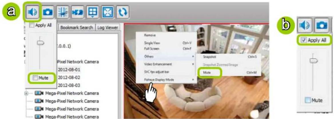
How to Change the Playback Layout
Changing the Layout of the Recorded Video Playback Window
VIVOTEK VAST Playback supports up to 16-CH simultaneous recorded video playback on a single monitor and allows you to change the layout of the recorded live video playback window based on the number of inserted devices.
Switch Video Channels
Drag-and-drop a video channel to another empty video window.

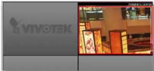
To switch two channels, drag-and-drop one view to the other, then the two channels will switch positions.
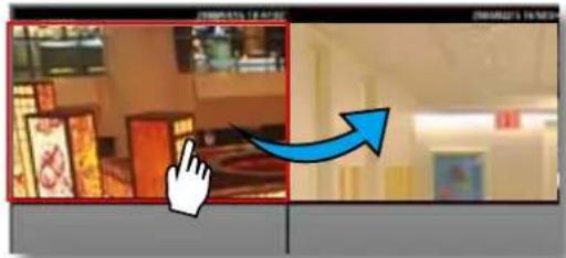
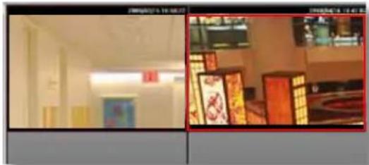
natural_image
Interior view of a room with bookshelves and a wall-mounted TV (no visible text or symbols)Layout Mode
Currently, a local display for the Layout 📋 has only one, 1x1, display option. If you access the NVR via a LiveClient on a remote PC, another 2x2 layout will be available.

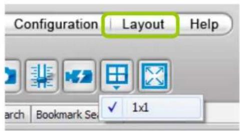
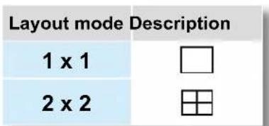
Maximize the Recorded Video Playback Window
■ Single View: to maximize a video cell to the entire video playback window
Double-click the video cell, or right-click the video cell and selec Single View. The selected video will expand to fill the entire Playback window as shown below.
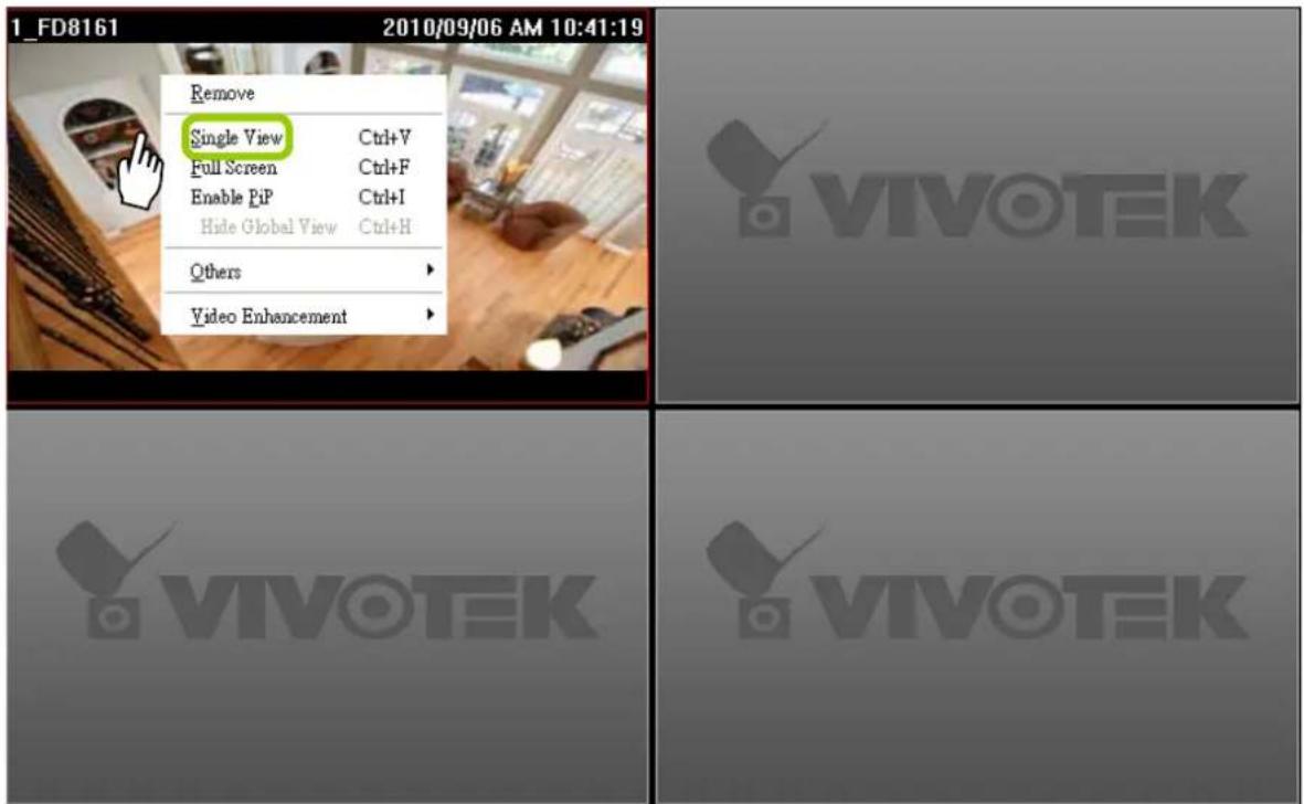
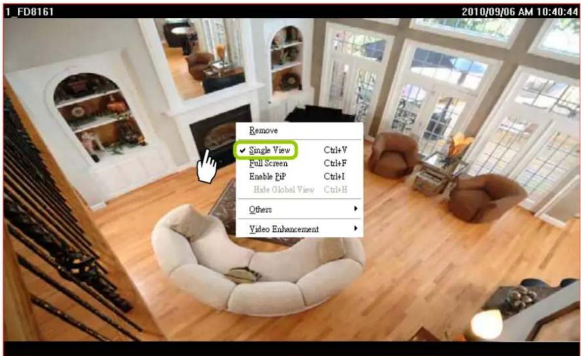
To restore to the original layout, double-click the video cell or right-click the video cell and uncheck Single View.
■ Full Screen: to maximize the video playback window to the entire screen
Click Full Screen 📧 on the quick access bar or right-click the video cell and select Full Screen. In addition, you can also click View > Full Screen on the menu bar to maximize the recorded video playback window.
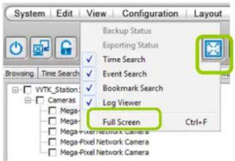
To restore to the original layout, right-click the video cell and uncheck Full Screen. You also can press the Esc button on the keyboard to leave the full screen mode.
How to Backup Recorded Video
In addition to the Schedule Backup function of VAST LiveClient introduced on page 61, the Playback utility can back up recorded video clips from the local database. Please open the Browsing page and follow the steps below to backup recorded video:
a. Select the target files.
■ To backup all recorded video of a selected device: Right-click the device and click Backup.
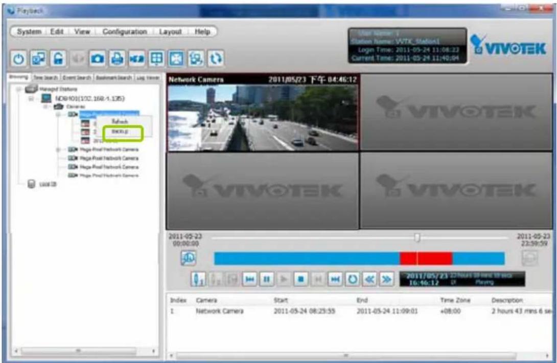
■ To backup all recorded video of the day: Right-click the option "date" and click Backup (or select the date and click the Backup button below).
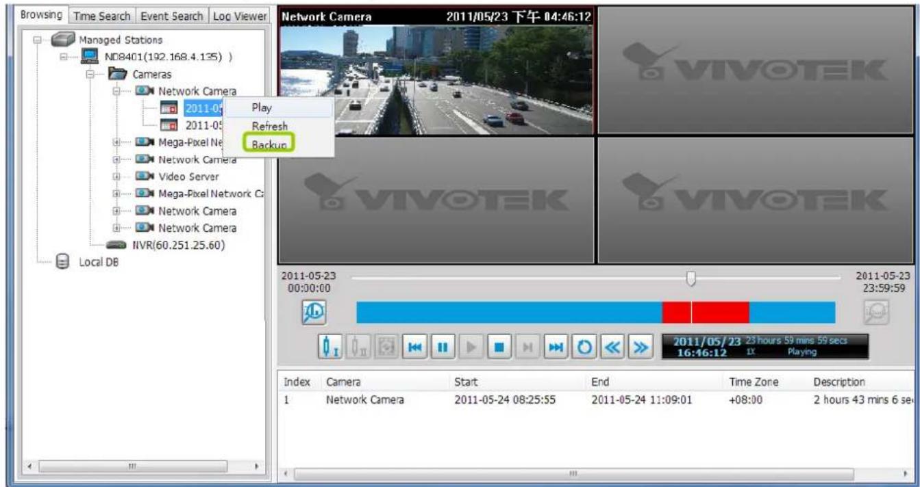
■ To backup part of the recorded video of the day: Select the date and choose the video clip(s) from video clip window. Then right-click the selected option(s) and click Backup. Note: Use the combination of the Shift key and left mouse click to select multiple video clips.
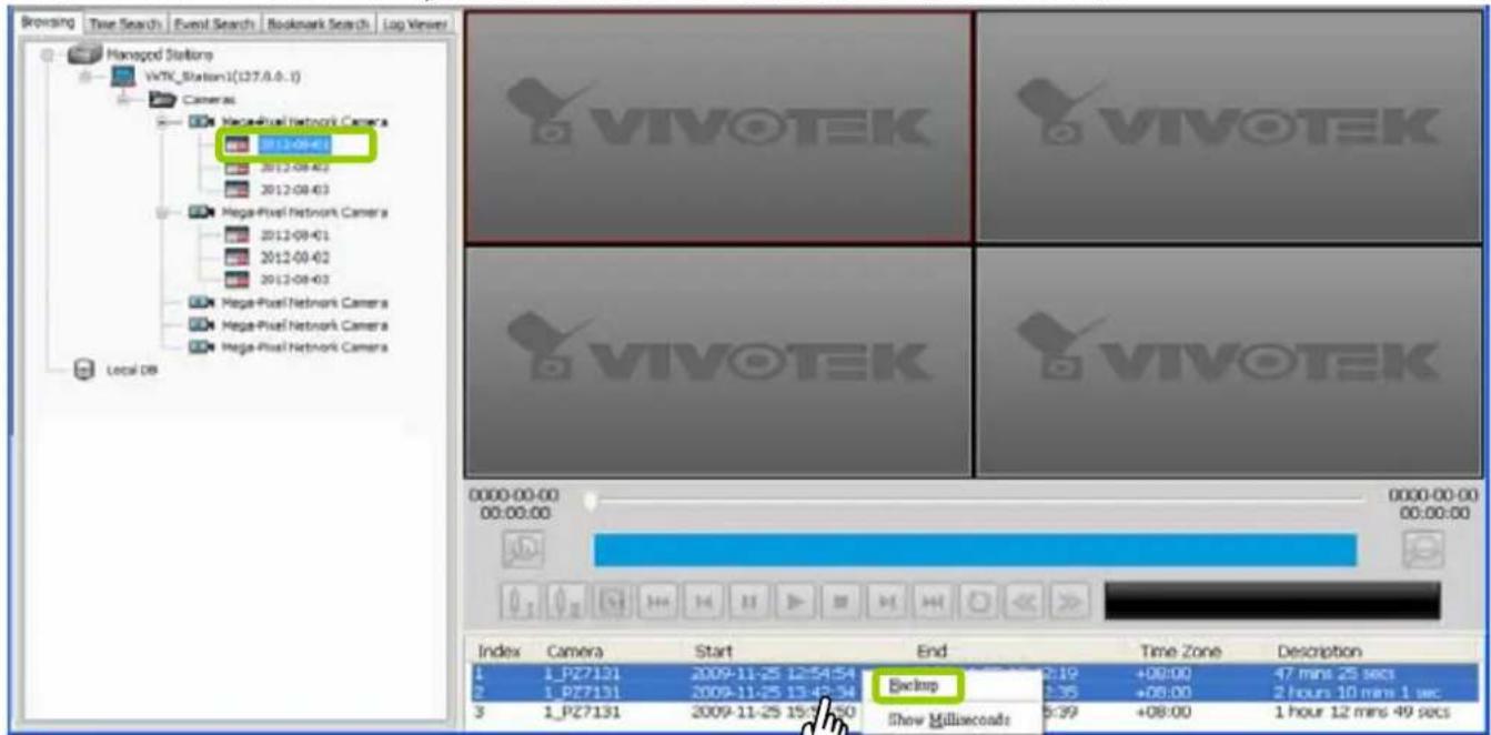
b. A Backup Settings window will pop up. Specify the time span and select a storage path (if you have a NAS or eSATA storage attached), then click Backup. The system will start to backup and popup a window showing the backup status.
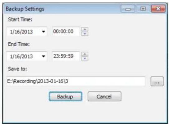
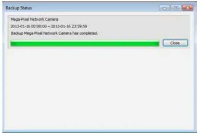
If you close the status window, you can also open it again by clicking View > Backup Status.
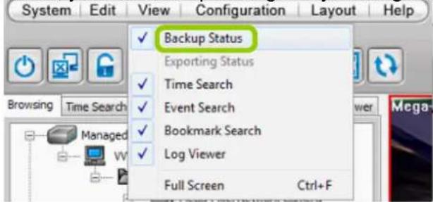
d. When the backup is complete, you will see an information dialog. The recorded data will be restored in the specific folder.
How to View Backup Files
The VAST Playback also allows users to playback backup files, including Schedule Backup by VAST LiveClient and Recorded Data Backup by VAST Playback.
Please follow the steps below to view backup files:
a. Right-click Local DB and click Add.
b. A Load Backup File window will pop up as shown below. Select the *.dif file to upload.
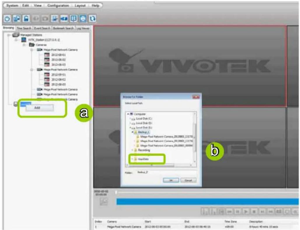
c. The following is an example of uploaded file, and you can double-click it or drag-and-drop it to a video cell to playback.
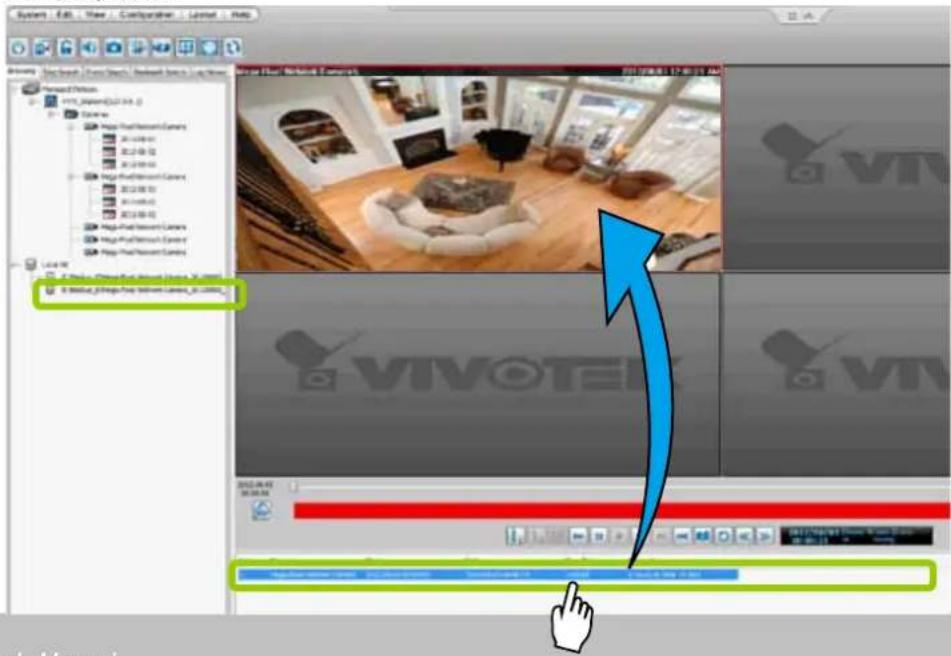

NOTE:
- The Backup function does not take place between the NVR system and a PC running the Playback utility.
- If you want to playback the backup files from the local database, you can also click Working Offline in the Login Window without the account information. The VAST Playback will launch as shown below.
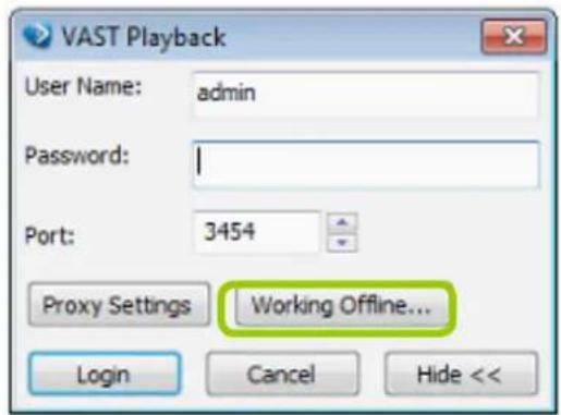
No user account information required
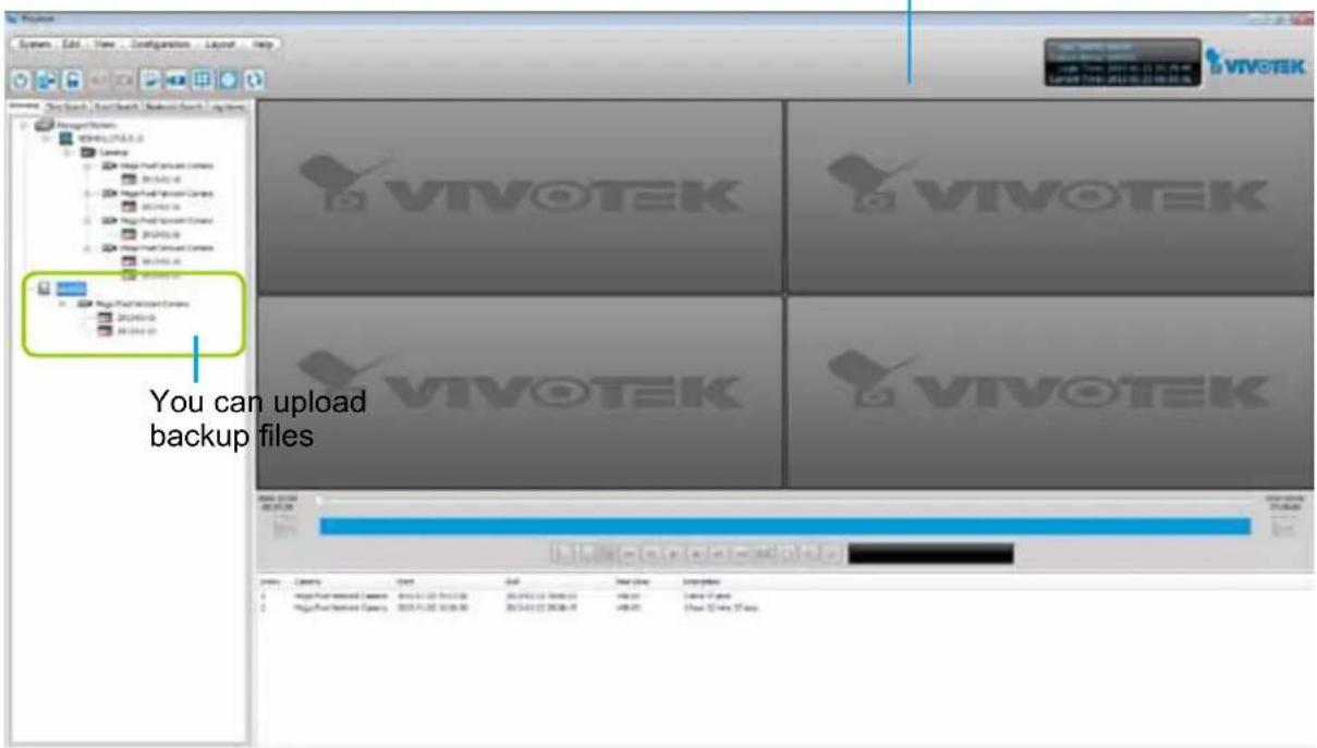
Model-specific Functions (FE Series Fisheye)
The VAST Playback program offers model-specific functions through a right-click menu. For example, if you playback a video clip made from an FE8171V or FE8172 series fisheye camera, a right-click on the playback screen will bring up the Display mode options. You can even exert mouse control while playing a recorded video. You can zoom in, zoom out, and change the view angle as if you are investigating a 3D scenario kept in a recorded point in time.
Note that ePTZ functions via the mouse control only takes place in a Regional view, e.g., the 1R or 1O3R mode.
The Display mode options and mouse control methodologies are identical to those described on page 54 and the following pages.
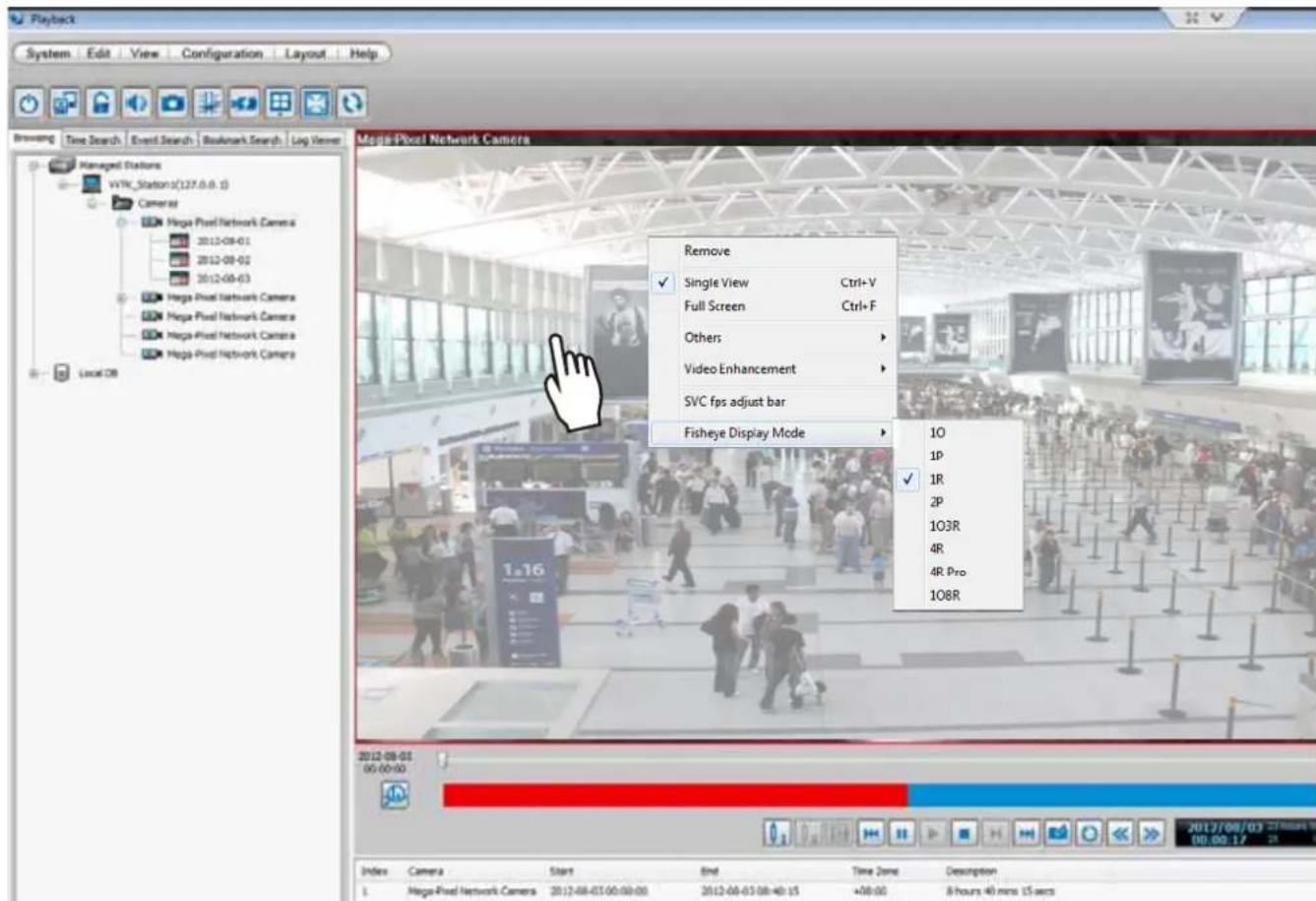
To configure the SVC-related feature:
- Right-click on the playback window of an SVC-enabled camera. Select SVC fps adjust bar.
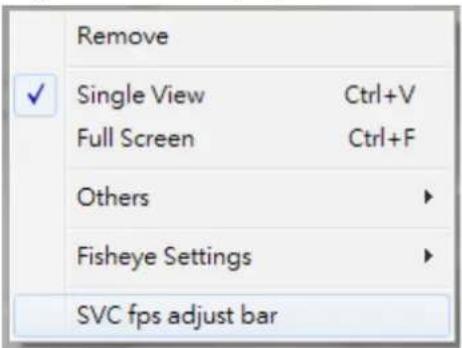
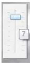
- A slide bar will appear above the view cell. Click and drag the slide bar. A numeric indicator will display the current selection. See below for the frame rates represented by the numeric indicator. Please refer to page 41 for the introduction of this feature. Changing the SVC vaule takes immediate effect on the number of frames per second shown with the video being played.
| Indicator Frame rate per second (fps) | |
| Maximum 30 | |
| 7 | 26 |
| 6 | 22 |
| 5 | 18 |
| 4 | 12 |
| 3 | 8 |
| 2 | 4 |
| 1 | 1 |
| Minimum 1/4 | |
How to Search for a Video Clip Taken at a Specific Time
Please follow the steps below to use Time Search function:
a. Open the Time Search page.
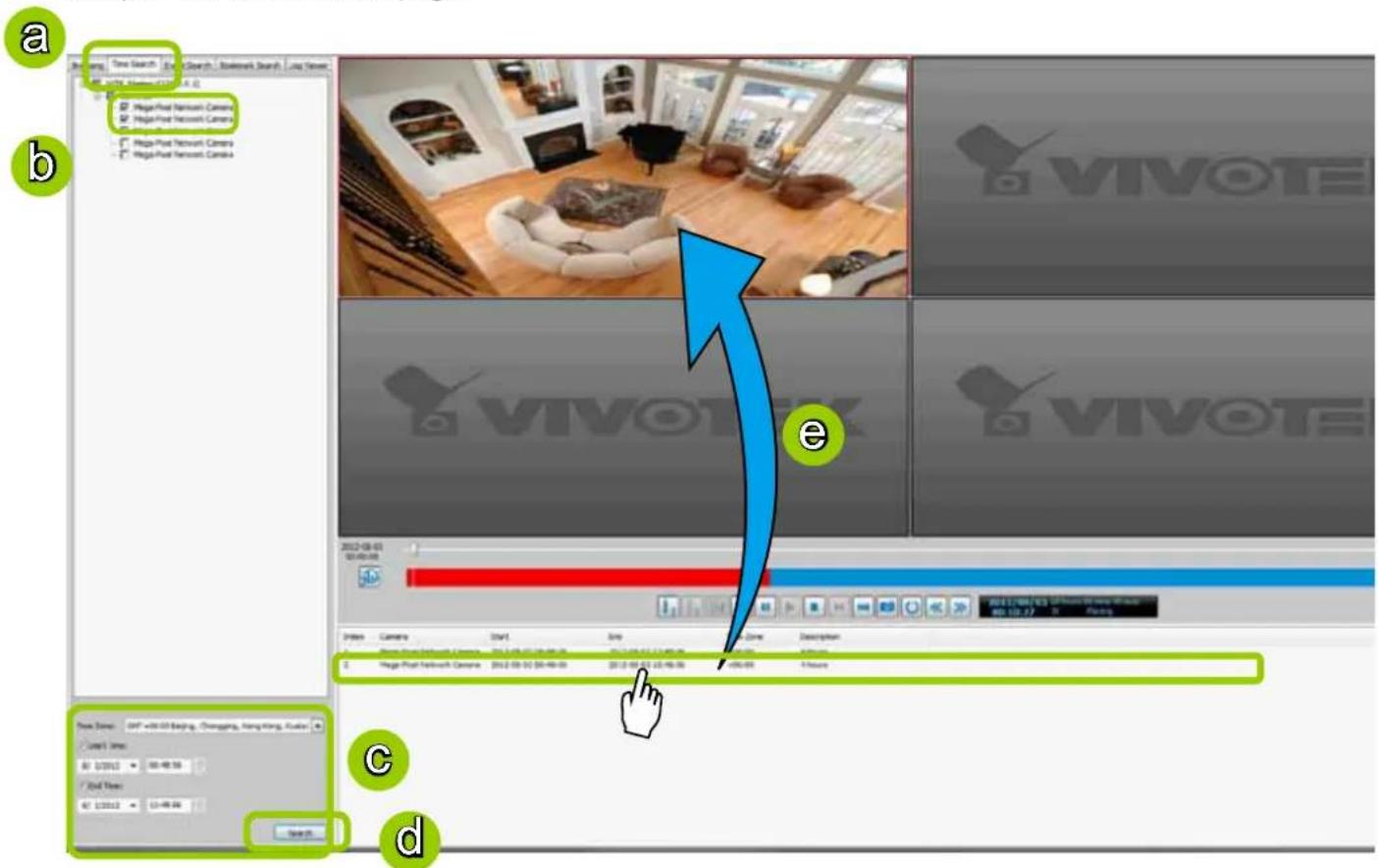
b. Select the target station(s)/device(s) that you want to search for video clips.
c. Specify the time span. You can choose to set up the start time only, the end time only, or both the start time and end time. The search results will only include the video clips within the time span. If you uncheck both the start time and end time, the search results will include all video clips recorded by the selected device(s).
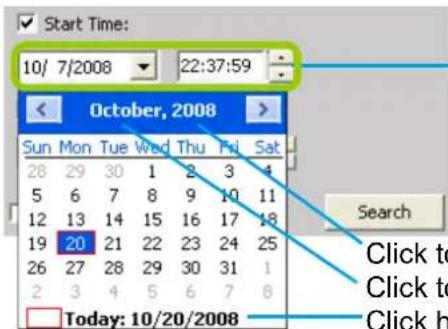
You can manually enter a specific time.
Click to select a year
Click to select a month from the drop-down list
Click here to move the focus to the current date
d. Click Search to start time search.
e. View the retrieved video clips.
How to Add a Bookmark
Bookmark is a convenient tagging function that allows your to pinpoint and extract a 20-second video clip from out of a video recording. When you see something of your interest while browsing through a recorded video,
-
Click on the Bookmark button,
-
Enter a name for the bookmark, such as "thief spotted."
-
You may enter a short description in the Description field. You may also search for the bookmarks you created later on.
A bookmark comprises a video clip starting from 10 seconds of before and ends at 10 seconds after the point in time you selected.
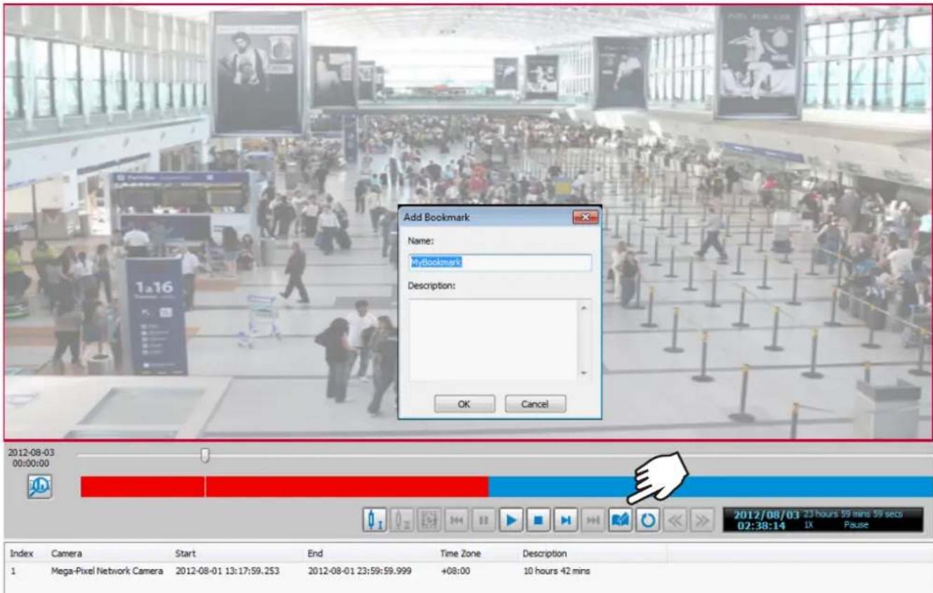
Please refer to page 178 for how to search for bookmarks.
How to Search for Events
The VAST Playback program offers users an intuitive event search engine for retrieving video clips from the database of recorded videos based on different search criteria such as motion, IVA, or DI events.
Please follow the steps below to search for recorded events:
a. Open the Event Search page.
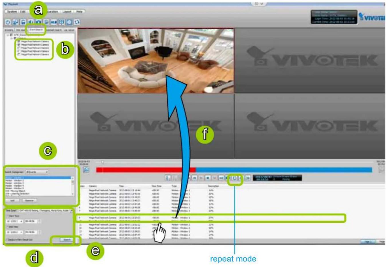
b. Select the target station(s)/device(s) that you want to search for events.
c. Specify the Event Category. For detailed information, please refer to Select Event Category on the following page.
d. Specify the time span for event search. You can choose to set up the start time only, the end time only, or both the start time and end time. The search results will only include the events within the time span. If you uncheck both the start time and end time, the search results will include all events from the selected device(s). Please refer to step c. on the previous page for detailed information.
e. Start event search. Please refer to page 176 for detailed information.
f. View the retrieved video clips. Double-click it or drag-and-drop it to the video cell. It will playback in repeat mode.
Note: The length of each video clip will depend on your settings of pre-event time & post-event time for the recording storage. The default setting is 20 seconds. For more infomation, please refer to page 87 for detailed illustration.
Select Event Category
The following introduces the event search categories: All Events, All Motion Events, All IVA events, All DI Events, Named DI Events, PIR, Tampering, and Tamperature. You can also add or remove customized events from the list.
Event Category- All Events
If you select the All Events category, all of the events including motion detection, digital input, and intelligent video analysis, PIR, tamper detection, and temperature alarm will be listed in the search results. You can click Add or Remove to change the search criteria options.
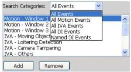
Event Category- All Motion Events
If you select the All Motion Events category, all detected motion events will be included in the search. You can click Add or Remove to change the search criteria options.
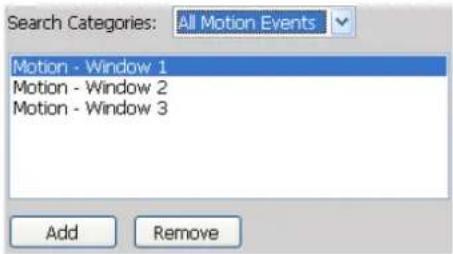
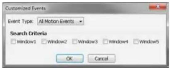
The parameters of the motion detection windows, such as motion percentage and the time of occurrence are also recorded in the database of the server. If you wish to change the parameters of the motion detection windows such as the position, size, detection sensibility, and motion percentage, please open a web console with the camera and make configuration change in the camera's Configuration page.
√ Enable motion detection
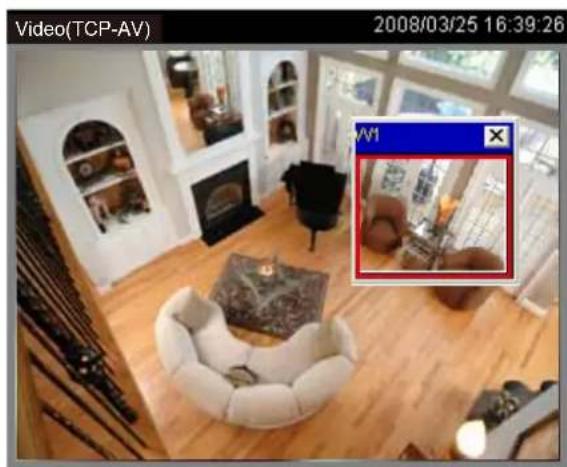
natural_image
Interior view of a modern living room with white furniture and large windows, showing a close-up of a red-labeled photo frame (no readable text or symbols)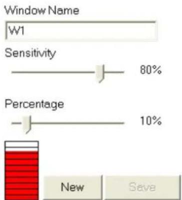
bar
| Category | Value (%) | |---|---| | Window Name | W1 | | Sensitivity | 80 | | Percentage | 10 | | New | Save |Event Category- All IVA events
If you select the All IVA events category, all detected IVA events will be included in the search. Cameras with embedded intelligent video content analysis are capable of detecting IVA events such as moving objects, loitering, and tamper detection.
The embedded video content analysis, superior to the conventional motion detection function, is capable of distinguishing between creature's motions, static backgrounds or natural movements such swaying trees, waves or sunsets to prevent false alarms from environmental noises.
With camera tamper detection, it can detect incidents such as camera redirection, blocking or defocusing of cameras, or even spray-paint. Additionally, a suspicious object in the pre-defined detection region will trigger alarms once the dwell time of the object is longer than the given time.
You can click Add or Remove to change the search criteria items.
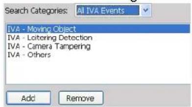
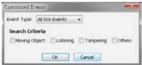
If you want to change the parameters of IVA, such as the detection region, loitering duration, etc, please link to the camera's Configuration page to modify the values.
![Trigger name: Trigger1 Enable this trigger Detection type Moving object detection Loitering detection - duration: 10 seconds [1~90] Camera tampering detection](/content/2026/06/1279498/images/b7e74379a4bc46c0b15a0913e1afdcce615db0ab4cbf93534e76fcc160195b87.jpg)
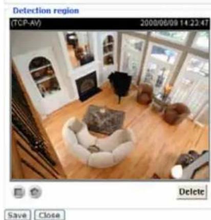
natural_image
Interior view of a modern living room with wooden flooring, armchairs, and large windows (no visible text or symbols)To draw a rectangle region, click on the rectangle button and drag on the video area. To draw a polygon region, click on the polygon button and click several points on the video area.
Event Category- All DI Events
If you select All DI Events category, all triggered DI signals will be included in the search. The DI events signify that there is a Digital-Input signal detected by the camera; its corresponding information such as DI-Trigger or DI-Normal signal and the time of occurrence are also transmitted and recorded in the database of the server.
You can click Add or Remove to change the search criteria options.
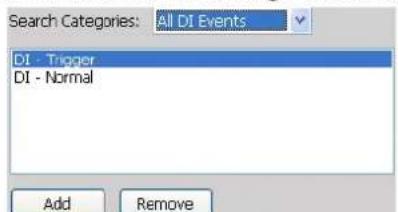
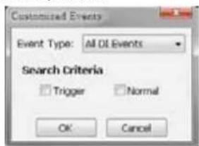
For more information about DI/DO settings on the connected devices, please refer to page 71 for detailed illustration.
Event Category- Named DI Events
This category allows you to select only Named DI Events--the DI device which you have renamed in the LiveClient. Please refer to Association Management on page 71 for more information about how to rename DI device.
Click OK and fill in the name you want to search on the left window.
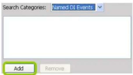
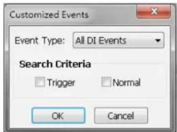
The new search criteria will be displayed in the search categories column as shown below. You can click Add or Remove to change the search criteria options.
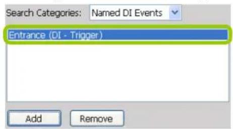
Start Event Search
After you specify all of the search criteria mentioned above, select or deselect the Display in new result list checkbox and click Search to begin event search.
■ If Display in new result list is unchecked, all search results will be displayed on the original event list window as shown below.
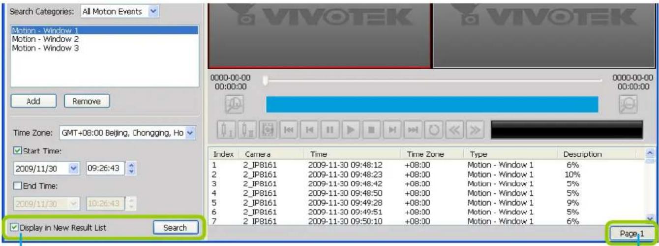
Deselected
Only one page
■ In the above screen, The Type column in the search result page shows the event category, and the Description field displays the motion percentage of the detection window. Please refer to page 165 for more information about Motion Events.
■ If you select Display in new result list and click Search, the search results will be displayed on a new page as shown below. This allows you to place the search results of each search category on an individual page. You can set up to 5 pages in the event list window.
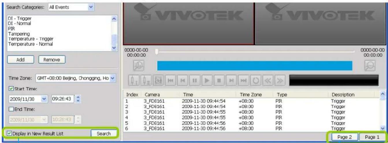
Selected
You can set up to 5 pages.
Backup the Event Videos
Please follow the steps below to backup the evnet videos on the results list:
a. Select the video clips you want to backup. You can select more than one video clip using the Shift key.
b. Right-click the selected video clips and click Backup.
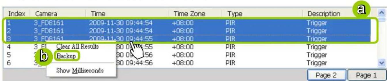
c. A Backup Settings window will pop up. For more information about how to set up the Backup Settings, please refer to page 164. For more information about how to view backup files, please refer to page 166 for detailed illustration.

NOTE:
The backup function does not take effect on a Playback separately installed on a client PC. Namely, you can not backup videos on an NVR to a client PC.
How to Search for a Bookmark
Please follow the steps below to use Bookmark Search function:
a. Click on the tabbed menu to open the Bookmark Search page.
b. Select the cameras which have video clips you have placed bookmarks on.
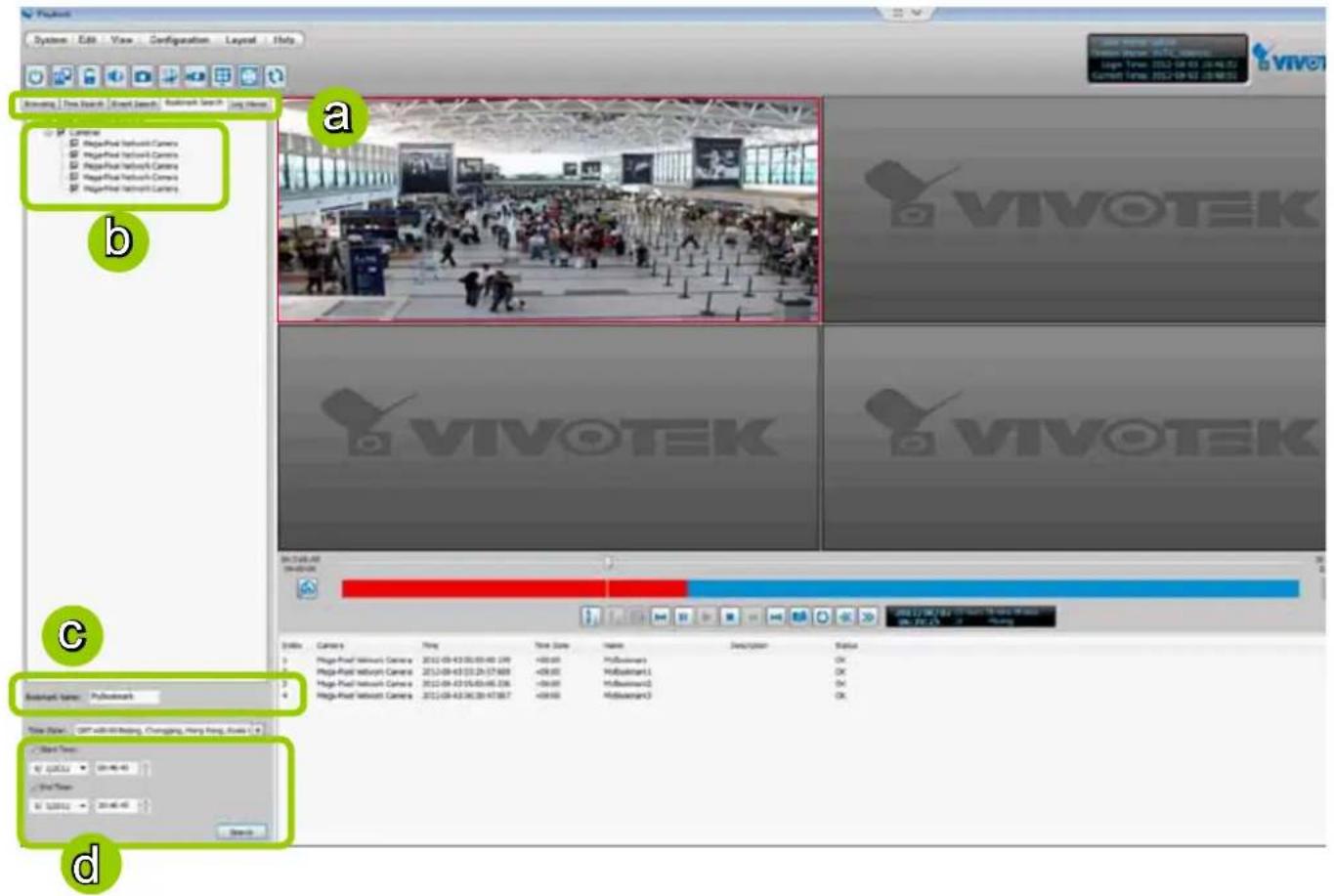
c. Enter the name of bookmark.
d. Specify a range of time during which the video streams were recorded and its points in time were bookmarked.
Click search. You can then click on a bookmark to display the short video clip extracted from within the recorded video.
To remove an existing bookmark, left-click to select an entry, and then right-click to display the Delete button. Bookmarks will be indicated as "Invalid" if the videos where the bookmarks were appended were erased, e.g., when the original recording was erased by cyclic recording.
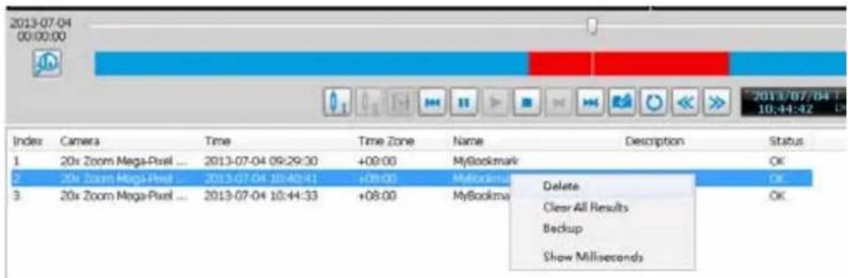
How to Search Logs
The VAST Playback program offers a convenient log engine for searching all local logs based on different search criteria such as log category, log type, and log level. The search results will be displayed in the log viewer window along with the detailed log history.
Please follow the steps below to search logs:
a. Open the Log Viewer page.
b. Select the target station where you want to search logs.
c. Specify the Log Category. For detailed information, please refer to Select Log Category on page 180.
d. Specify the User Account. If you have added other user accounts to the station, you can select one to search its login history. For detailed information about user account, please refer to How to Manage User Accounts on page 66.
e. Specify the Search Result. Select All to display all search results; select Success to display successful log activities only; select Fail to display failed log activities only.
f. Specify the Log Type. For detailed information, please refer to Select Log Type on page 180.
g. Specify the Log Level. For detailed information, please refer to Select Log Level on page 180.
h. Specify the search time span. You can check the start time only, the end time only, or both the start time and end time. The search will only include the events within the time span. If you uncheck both the start time and end time, the search will include all events saved by the server. Please refer to page 170 for detailed information.
i. Start the log search and the results will be displayed on the log list window.
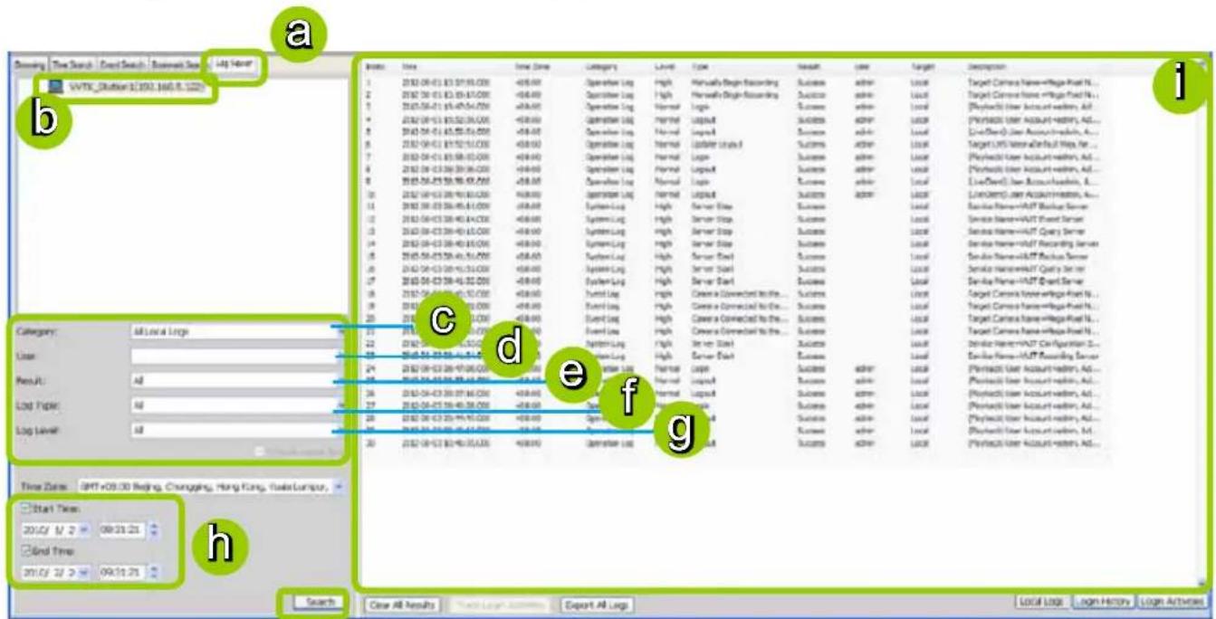
i
Select Log Category/Log Type/Log Level
The following table shows the breakdown of log category, level, and type. The search results will be different according to your selections.
| Log Categories Log Levels Log Types | ||
| Operation Log | Normal | Login / LogoutInsert UserUpdate User NameUpdate User PasswordUpdate User PrivilegeDelete UserInsert CameraUpdate Camera InformationDelete CameraSet Storage GroupInsert Recording Schedule / Update Recording Schedule / Delete Recording ScheduleInsert Event Management / Update Event Management / Delete Event ManagementInsert Storage Group / Update Storage Group / Delete Storage GroupInsert Recording Path / Update Recording Path / Delete Recording PathInsert Camera to the Storage GroupUpdate Camera information in the Storage GroupDelete Camera from the Storage GroupMove Recording PathMove Camera to another Storage GroupInsert Layout / Update Layout / Delete LayoutSet Digital OutputUpdate Scheduled BackupUpdate Server PortSet Proxy ServerSet UPNPSet DDNS ServerCreate Directory / Rename Directory / Delete DirectoryInsert SMTP Server / Update SMTP Server / Delete SMTP ServerInsert Network Storage Device / Update Network Storage Device / Delete Network Storage DeviceSet GSM ModemSet DI/DO RenameSet Relay SettingsUpdate Web Access Information |
| High | Manually Begin RecordingManually Stop Recording | |
| System Log High | Server Start / Server StopVirtual Memory LowNetwork Lost | |
Log Categories Log Levels Log Types
Event Log High
Camera Disconnected from the Server / Camera Connected to the Server
Camera Recording Start / Camera Recording Stop
Start Scheduled Backup / Stop Scheduled Backup
Event Trigger
Search All Local Logs
![Log Category Log Level Log Type Index Time New Date Category Level Type Result User Target Description 1 2012-08-01 13:17:39.000 +00:00 Operation Log high Manually Begin Recording Success admin Local Target Camera Name=white-Fixed_... 2 2012-08-01 13:19:17.000 +00:00 Operation Log high Manually Begin Recording Success admin Local Target Camera Name=white-Fixed_... 3 2012-08-01 13:47:04.000 +00:00 Operation Log Normal Logit Success admin Local [Plabact] User Account-hedron, Ad... 4 2012-08-01 13:52:26.000 +00:00 Operation Log Normal Loguit Success admin Local [Plabact] User Account-hedron, Ad... 5 2012-08-01 13:52:51.000 +00:00 Operation Log Normal Loguit Success admin Local [LiveClient] User Account-hedron, A... 6 2012-08-01 13:52:51.000 +00:00 Operation Log Normal Logiter Laced Success admin Local TargetC#] Home=white-Fixed_Req, No... 7 2012-08-01 13:58:33.000 +00:00 Operation Log Normal Logit Success admin Local [Plabact] User Account-hedron, Ad... 8 2012-08-01 13:59:36.000 +00:00 Operation Log Normal Loguit Success admin Local [Plabact] User Account-hedron, Ad... 9 2012-08-01 13:59:36.000 +00:00 Operation Log Normal Logit Success admin Local [LiveClient] User Account-hedron, A... 10 2012-08-01 13:59:46.000 +00:00 Operation Log Normal Loguit Success admin Local [LiveClient] User Account-hedron, A... 11 2012-08-01 13:60:46.000 +00:00 System Log high Server Stop Success success Local Service Name=H4ST Backup Server 12 2012-08-01 13:61:46.000 +00:00 System Log high Server Stop Success success Local Service Name=H4ST Query Server 13 2012-08-01 13:62:46.000 +00:04 System Log high Server Stop Success success Local Service Name=H4ST Recording Server 14 2012-08-01 13:63:46.000 +03:36 System Log high Server Start Success success Local Service Name=H4ST Query Server 15 2012-08-01 13:64:46.000 +33:36 System Log high Server Start Success success Local Service Name=H4ST Query Server 16 2012-08-01 13:65:46.000 +33:36 System Log high Server Start Success success Local Service Name=H4ST Event Server 17 2012-08-01 13:66:46.000 +33:36 System Log high Server Start Success success Local Service Name=H4ST Query Server 18 2012-08-01 13:67:46.000 +33:36 System Log high Server Start Success success Local Service Name=H4ST Recording Server 19 2012-08-01 13:68:46.000 +33:36 System Log High Server Start Success success Local Service Name=H4ST Configuration S... 20 2012-08-01 13:69:46.000 +33:36 System Log High Server Start Success success Local Service Name=H4ST Recording Server 21 2012-08-01 13:73:46.000 +33:36 System Log High Server Start Success success Local Service Name=H4ST Accounting, Ad... 22 2012-08-01 13:74:46.000 +33:36 System Log High Server Start Success success Local Service Name=H4ST Accounting, Ad... 23 2012-08-01 13:75:46.000 +33:36 System Log High Server Start Success success Local Service Name=H4ST Accounting, Ad... 24 2012-08-01 13:75:46.075.555 +48:555 - Output Lognormal LogitSuccess adminLocal [Plabact] User Account-hedron, Ad... 25 2012-08-01 13:75:46.555 - Output Lognormal Lognormal LoguitSuccess adminLocal [Plabact] User Account-hedron, Ad... 26 2012-08-01 13:75:46.555 - Output Lognormal Lognormal LoguitSuccess adminLocal [Plabact] User Account-hedron, Ad... 27 2Q/EB/EB/EB/EB/EB/EB/EB/EB/EB/EB/EB/EB/EB/EB/EB/EB/EB/EB/EB/EB/EB/EB/EB/EB/EB/EB/EB/EB/EB/EB/EB/EB/EB/EB/EB/EB/EB/EB/EB/EB/EB/EB/EB/EB/EB/EB/EB/EB/EB/EB/AB Close All Results Have Long Action - Export All Log Click to export all search results from the list Click to remove all search results from the list](/content/2026/06/1279498/images/a8c49b32f154058f157d4b25bda5fd6dc33da53966e6a8852f0038ed5f343c24.jpg)
Search Login History
Select Login History from the log category field and click the Search button below, the search results, including all login logs, will be displayed on the Login History page.
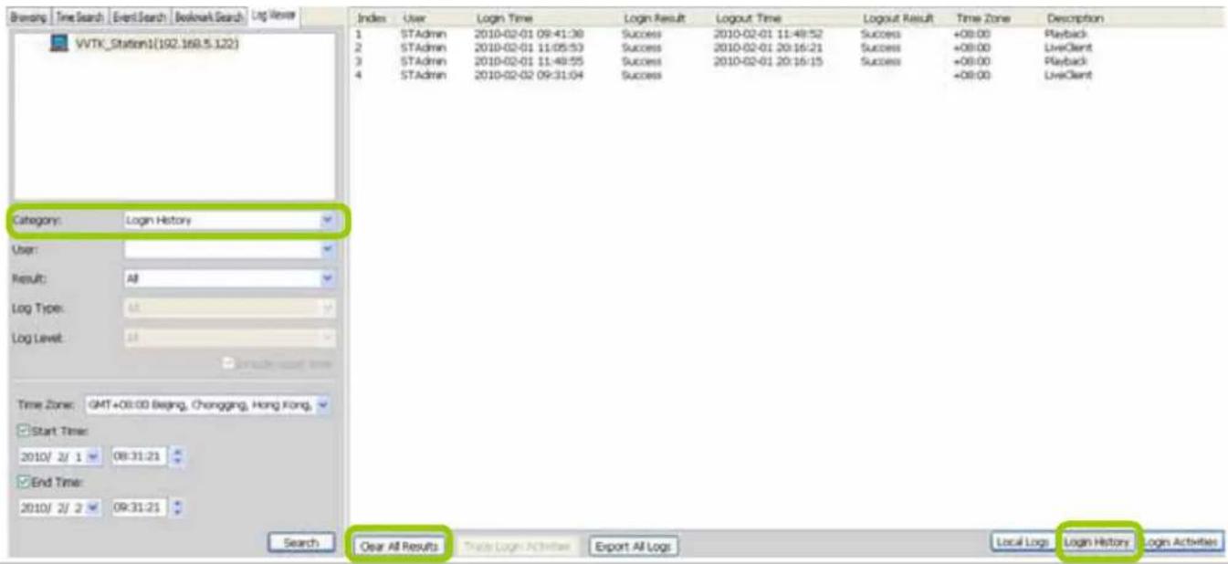
Search Login Activities
This function allows you to search the operations the user performed during the login period of time. You can search for login activities on the Local Logs or Login History page.
■ Search Login Activities on the Local Logs page:
a. Click on the Local Logs page.
b. Select a login/logout option from the list.
c. Click Trace Login Activities (or you can right-click the selected login/logout option on the list, then click Trace Login Activities).
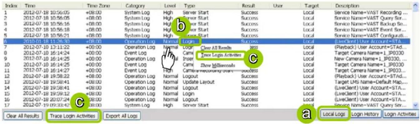
d. The search results of the login activities will be displayed on the Login Activities page as shown below.
| Index | Time | Time Zone | Category | Level | Type | Result | User | Target | Description |
| 1 | 2012-07-18 11:26:30 | +08:00 | Operation Log | Normal | Login | Success | Admin | Local | (LiveClient) User Account=STA... |
| 2 | 2012-07-18 16:14:25 | +08:00 | Operation Log | Normal | Insert Camera | Success | Admin | Local | New Camera Name=1_IP833D, ... |
| 3 | 2012-07-18 19:58:41 | +08:00 | Operation Log | Normal | Update Layout | Success | Admin | Local | Target LMS Name=Default Map,... |
| 4 | 2012-07-18 19:58:41 | +08:00 | Operation Log | Normal | Logout | Success | Admin | Local | (LiveClient) User Account=STA... |

■ Search Login Activities on the Login History page:
a. Click on the Login History page.
b. Select a login/logout option from the list.
c. Click Trace Login Activities (or you can right-click the selected login/logout item on the list and click Trace Login Activities).


flowchart
graph LR
    A["Clear All Results"] --> B["Trace Login Activities"]
    B --> C["Export All Logs"]
    C --> D["Local Logs"]
    D --> E["Login History"]
    E --> F["Login Activities"]
d. The search results of the login activities will be displayed on the Login Activities page as shown below.
| Index | Time | Time Zone | Category | Level | Type | Result | User | Target | Description |
| 1 | 2012-08-01 11:05:53 | +08:00 | Operation Log | Normal | Login | Success | Admin | Local | (LiveClient) User Account=STA... |
| 2 | 2012-08-01 20:16:21 | +08:00 | Operation Log | Normal | Logout | Success | Admin | Local | (LiveClient) User Account=STA... |


NOTE:
When you select All in the Log Level field, the search results will include all log levels. If you select Low in the Log Level field and select Including above level as shown in the picture below, the search results will include all levels of logs. However, if you select Normal in the Log Level field and select Including above level as shown in the picture on the right below, the search results will only include Normal-level and High-level logs.


How to Configure Client Settings
On Client Settings, you can configure Snapshot Settings, Export Settings, View Settings, Proxy Settings, and General Settings. It allows you to save snapshots and media files on the local computer.
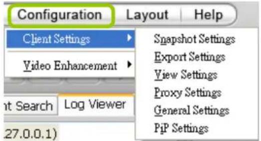
Snapshot Settings
When you play a recorded video, VAST Playback also allows you to take snapshots. For detailed information about Snapshot Settings, please refer to page 125.
Export Settings
When you playback a recorded video, the VAST server allows you to export part of the recorded video in EXE, 3GP, or AVI format to your local computer. Before exporting a media file, please set up Export Settings first. For detailed information about how to set up EXE, 3GP, and AVI Export Settings, please refer to Record Settings on page 127.
Export an EXE/3GP/AVI File
Please follow the steps below to convert part of an EXE/3GP/AVI file of recorded video:
a. Playback a video clip from which you want to export a media file.
b. Set a period of time. Move the timeline slider bar to the desired start time and click Marker I. Move the timeline slider bar to the desired end time and click Marker II.
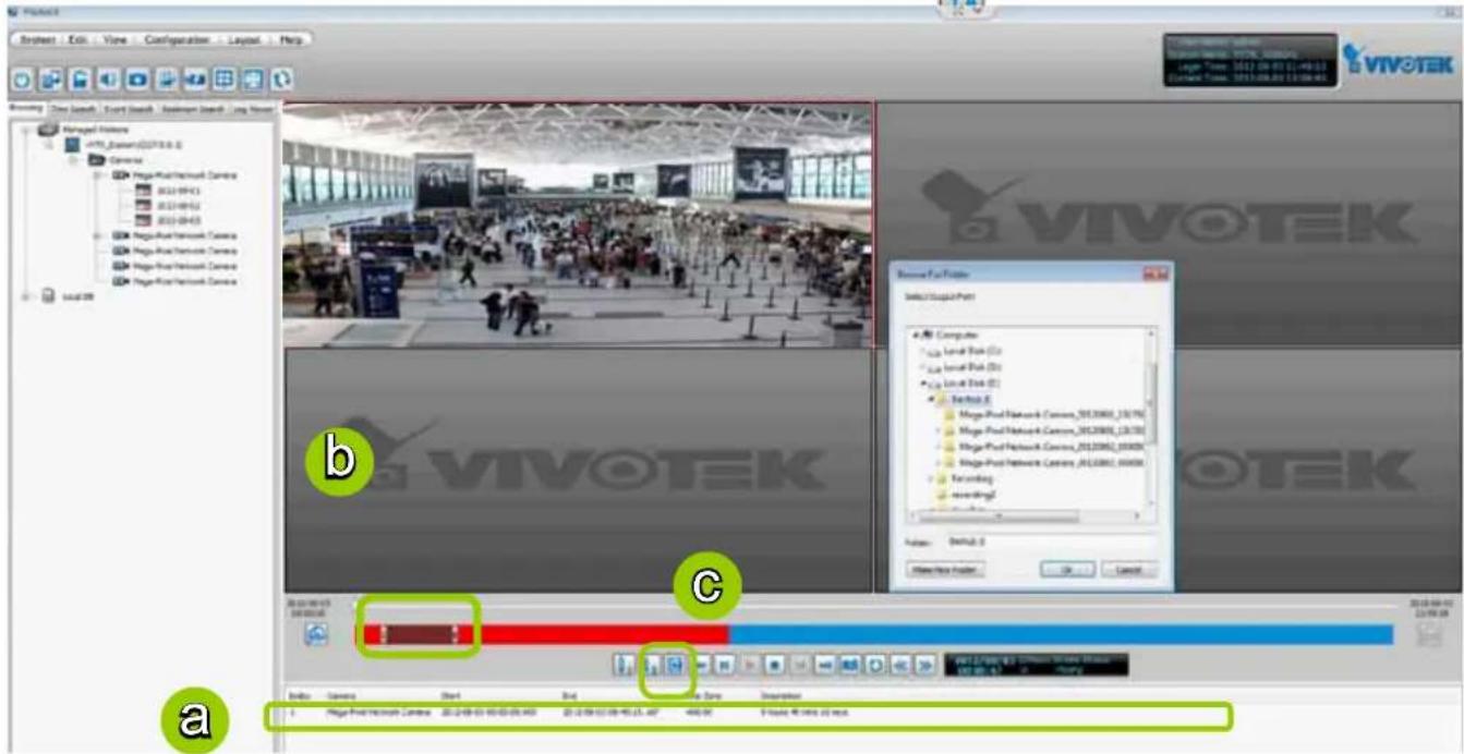
c. Click Export EXE/3GP/AVI, the server will start to export the data and popup a window showing the exporting status. If you close the status window, you can also open it again by clicking View > Exporting Status.
d. When the backup is complete, you will see an information dialog. The exported data will be restored in the preset storage folder on your local computer (C:\Program Files\VIVOTEK Inc\VAST\Client\Playback\Export).
Note that the local computer has a Playback instance that is separately installed. If you are running Playback on the NVR, you can backup to the local disks or USB devices.
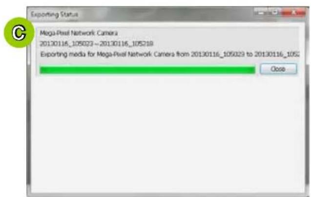
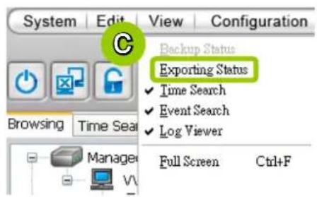
View Settings
This section allows you to set up the display mode of video cell. For detailed information about View Settings, please refer to page 133.
Proxy Settings
Please refer to page 143 for detailed illustration.
General Settings
System Settings
Please refer to page 135 for detailed information.
Display Settings
■ Enable de-interlace function: Select this option if your connected device does not support de-interlace function. For example: VS7100.
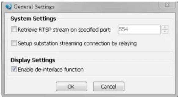
How to Configure Video Enhancement
The Playback also allows you to enable post-image enhancement and defog for video viewing. Please refer to page 146 for detailed information.
How to Search for a Device on the Hierarchical Management Tree
The Playback also allows you to conveniently search for an inserted device. Please refer to page 151 for detailed information.
How to Lock VAST Playback for Security Concerns
If you happen to be away from your computer, for security reasons, we suggest you lock the program. When VAST Playback is locked, the user must enter the correct password to unlock and access the program again.
■ To lock Playback, click Unlock 🔒 on the quick access bar or click System > Lock on the system menu. The Unlock 🔒 icon will then turn into Lock 🔒
■ To unlock Playback, click and enter the correct password in the popup window.
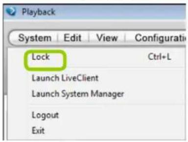
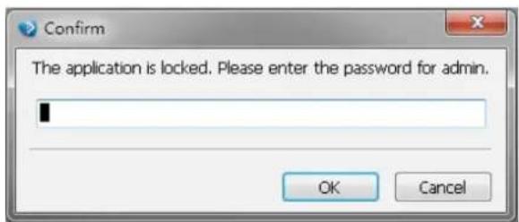
How to Log out from the VAST Server
To log out from the current server, click the station and click Logout on the quick access bar or click System > Logout on the menu bar. You can also right-click the station and click Logout. A confirmation window will pop up. Click OK to confirm or Cancel to return to the VAST Playback window.
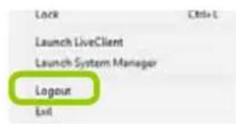
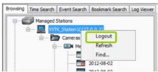
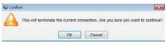
How to Exit VAST Playback
To exit VAST Playback, click Exit ☐ on the quick access bar or click System > Exit on the menu bar. A confirmation window will pop up. Click OK to confirm or Cancel to return to the VAST Playback window. When you exit the program, your user account will be automatically logged out from the current server.
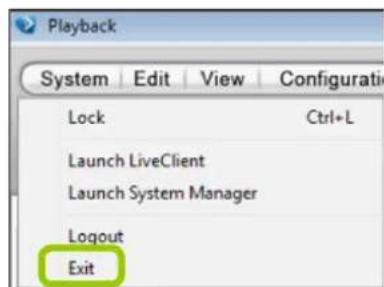
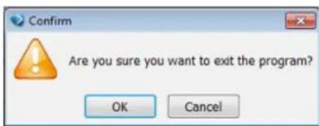
Chapter Four Auxiliary Utilities
In addition to LiveClient and Playback, the NVR system comes with a variety of auxiliary utilities including:
| Utility Description | ||
 | Setup Wizard The Setup Wizard has been described in Chapter One | |
 | Service Services enables you to restart or stop the embedded NVR server (VAST server). | |
 | Import/ Export The Import/ Export utility helps preserve current system configuration or reload a previously-saved configuration. | |
 | Installation Wizard 2 | The IW2 utility offers a glimpse of VIVOTEK cameras and the access to them in a local area network. |
 | Shepherd You can use shepherd to quickly duplicate individual camera configuration (system, video streams, network, security, etc.) to multiple cameras. Please refer to page xxx for more about this utility. | |
 | Upgrade The Upgrade provides access to NVR system updates. | |
 | File Manager The File Manager helps locate particular system or video data when the need arises, say, for retrieving forensic evidences. | |
 | Keyboard If a keyboard is not available, use this virtual keyboard for entering data. | |
Below are the functions available through the menu bar:
| Menu Description | |
| Disk Status Disk | Status provides a glimpse of Logical Volumes, Physical disk statuses, HDD status reported through S.M.A.R.T. (Self-Monitoring, Analysis and Reporting Technology), and a test tool to check the integrity of individual disk drives. |
| Network Status | Displays the network statuses of the NVR's two GbE Ethernet ports, including network type, IP address, subnet, and gateway information. |
| System Status | Reports system overall working status. |
Service
Chances are you may need to stop and restart the embedded VAST server. On occasions such as stopping a recording task, server reported errors, or after you update the software components of the VAST server, you can manually stop and then restart the service.
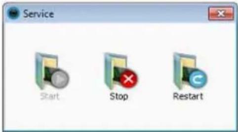
Import and Export Utility
VAST supports import and export utility for user to keep record of all server settings. You can use the export file to copy the configuration on another host.
Please follow the steps below to export the server settings:
a. Double-click on the Import /Export Utility shortcut.

b. The Import/Export Utility window will prompt. Click Export and select a location. Enter a file name. The system will start to export a .bin file. This helps preserve your system configuration.
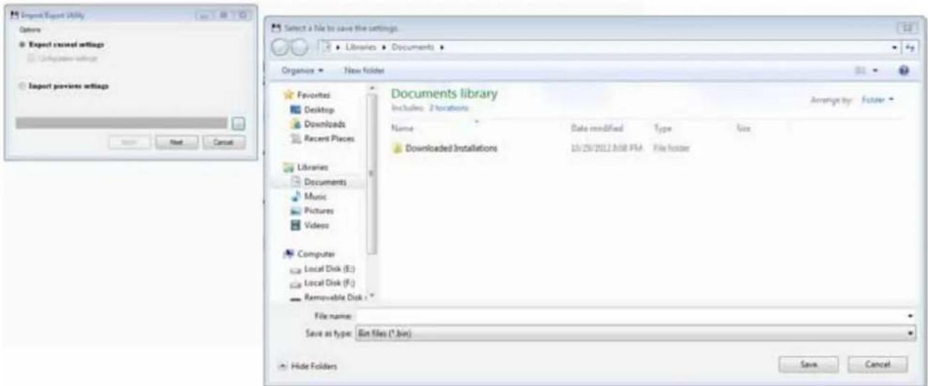
The exporting process may take several minutes. Click Close when the process is completed.
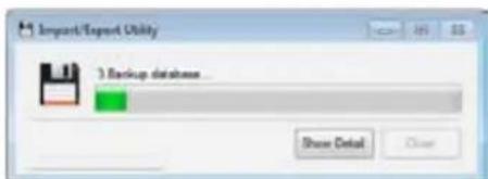
To import a previously saved configuration:
a. Click Import previous settings.
b. Use the browse button to locate a configuration bin file.
c. Click open. A message prompt will appear warning you about the replacement of current settings.
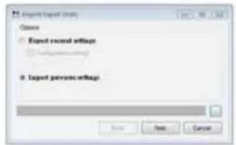
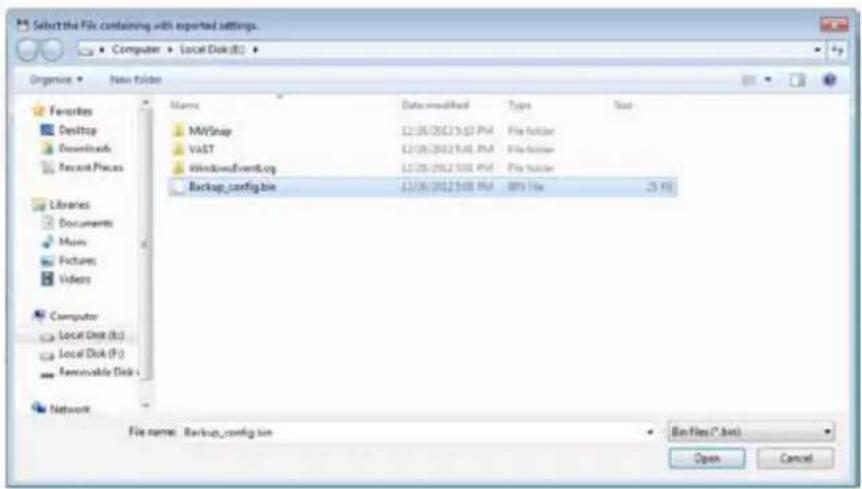
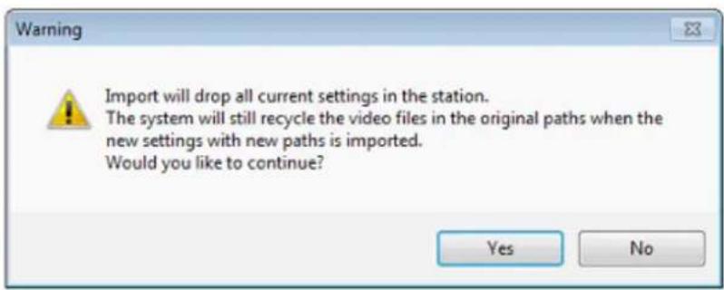
The process may take several minutes to complete. Click Close to finish the process. Your system should now be in sync with the imported configuration.
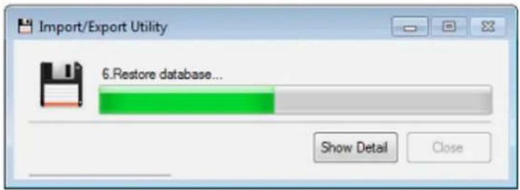

NOTE:
Currently you can use this function to back up or restore your configuration on one machine. You can not use it to duplicate one configuration profile to multiple NVR systems.
Installation Wizard 2

This is the same utility that comes with every VIVOTEK's network camera. You can use it to scan the local network for all VIVOTEK's network cameras, NVR systems, and video servers. Please refer to cameras' software CD for its operation manual.
In addition to opening a direct web console with a camera, you can also use the Camera Configuration function for an immediate access to the streaming, Audio, Remote Focus, and NTP settings.
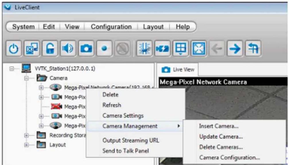
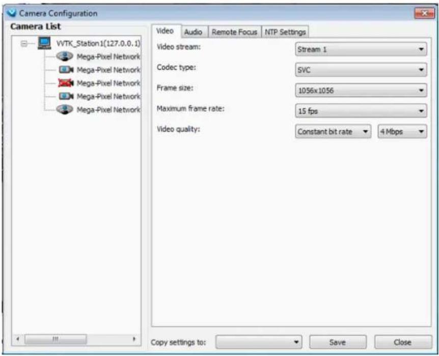
Shepherd

The Shepherd is handy in duplicating one single camera's configuration to multiple cameras. In this way, you do not need to open web consoles with individual cameras for a multiple times. Before using this function, you may open a web console with one of the camera, and configure all aspects of camera settings including network, general settings, security protocols, and media-related settings.
a. Double-click on the Shepherd shortcut. Note that the target cameras must reside in the same network segment as your NVR's LAN port.
b. The Shepherd window will prompt. Select a camera (supposedly the one that you have configured satisfactory System, Network, and Media settings) by a left click.
c. Click Get Camera Settings. An Export Camera Settings window will prompt.
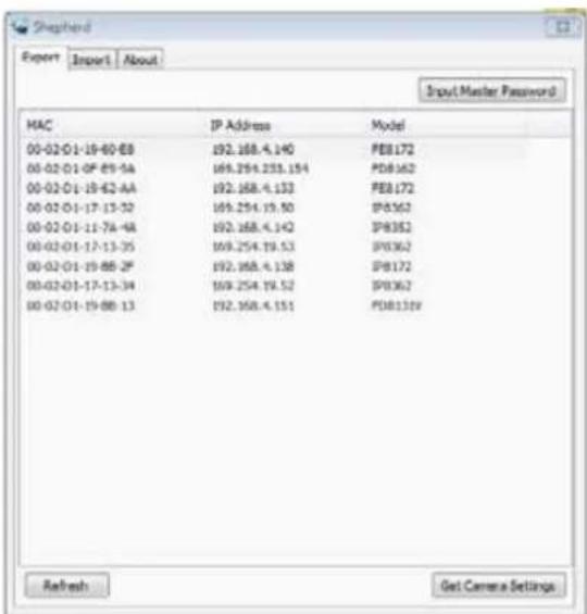
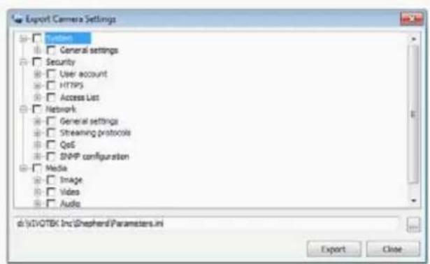
d. Unfold menu items and select the items you wish to duplicate to other cameras.
e. Click Export. A Paramters ini file will be created into the D:\VIVOTEK Inc\Shepherd folder.
f. Click to open the Import tabbed menu. Use the Browse button to open the Parameters file.
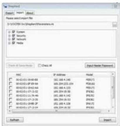
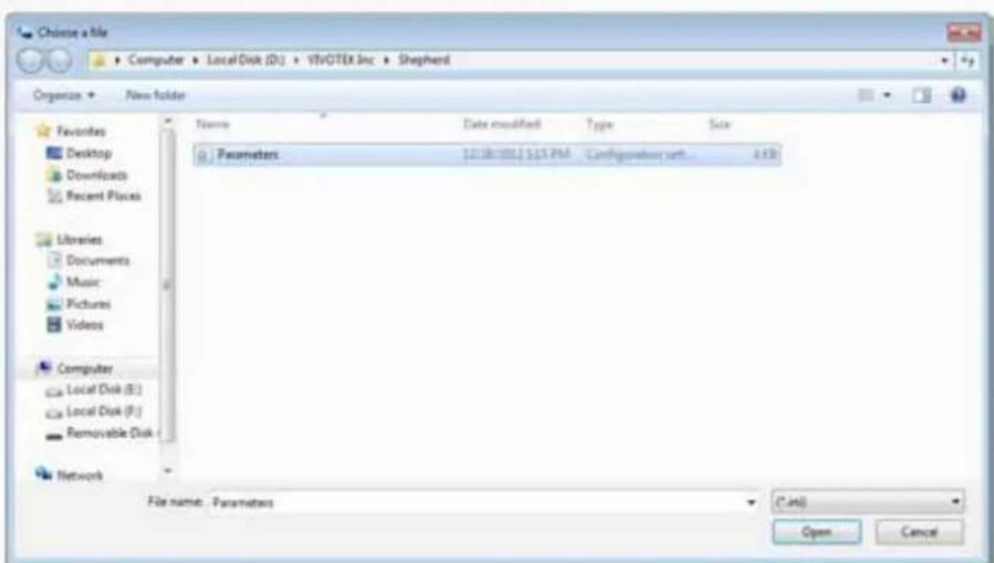
g. Parameters will be listed, select the parameters you want to duplicate. Please unfold the menu and check carefully on each configuration detail.
h. Select the cameras which will receive the duplicate parameters.
i. A warning message will remind you of the IP address. If you configured a static IP on the source camera, it is recommended to change it to the automatic IP address setting.
j. A progress bar will appear on the screen.
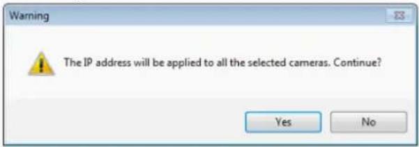
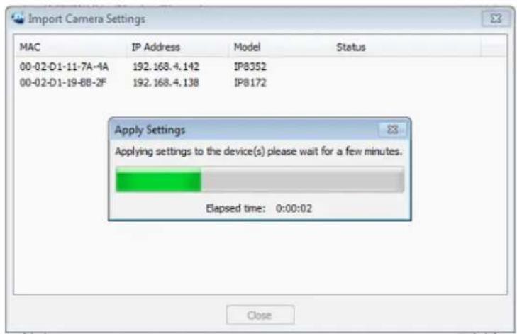
k. Another message will prompt indicating the completion of the process.
Upgrade

Software upgrade packages will be released on VIVOTEK's support website. You can download these files, and double-click the Upgrade shortcut to open the utility. Please consult VIVOTEK's technical support and the release note before applying upgrades.
Locate the upgrade package and click open. The upgrade process should be completed within minutes. Please note that during the upgrade, the VAST server service will be stopped and restarted. During the time, recording tasks will be temporarily interrupted.
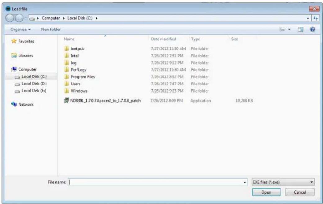
File Manager

The File Manager provides access to the file browser window of the embedded operating system.
By default, the recorded video files should be recorded to the E: volume, and you can use the Export EXE and other similar functions in the Playback utility to extract video clips to the E: volume. You can then retrieve the video clips using a USB drive.
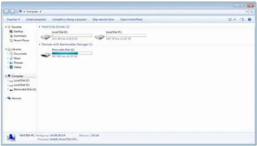
Keyboard

Use the virtual keyboard if you do not have a keyboard attached to the USB port.
Disk Status
Click on the tabbed menu on the desktop to enter the Disk Status window. The first information is the Logical volume working status.

VIVOTEK
Control Center
Disk Status
Network Status
System Status
![Logical volume Physical disk Name Total size Free size State File system (E:) [Disk: 1] 149 GB 40 GB Ready NTPS](/content/2026/06/1279498/images/934cf9aa031ca10d12a62530416bfe29dcd19d662e2f28df890aa603135ed464.jpg)
The second window displays the working status of individual disk drives, including model name, capacity, S.M.A.R.T., state, and temperature. Note that if a hard drive is stated as an ArrayMember, the physical drive has already been included into a logical, multi-drive configuration such as RAID0 or RAID1.
Click the tabbed menu below to see more information such as the current working status reported through SMART.
![Logical volume Physical disk Model Capacity SMART State Temperature 1 ST3160811AS 160 GB PASSED ArrayMember 44℃ (111.2℉) 2 ST3160811AS 160 GB PASSED ArrayMember 43℃ (109.4℉) Disk information SMART Nepal Model family: Seagate Barracuda 7200.9 Model number: ST3160811AS Serial number: 6PTOQSZ7 Firmware version: 3.AAE Capacity: 160,041,885,696 bytes [160 GB] ATA version: 7 ATA standard: Exact ATA specification draft version not indicated](/content/2026/06/1279498/images/9015cec4a536c7ce66e9a44e3a1e322f77ac70e0723e2014d16095f02b39dc50.jpg)
S.M.A.R.T. is short for Self-Monitoring, Analysis, and Reporting Technology. S.M.A.R.T. provides near-term failure prediction that monitors predetermined disk drive attributes that are susceptible to degradation over time. Predictions are limited to the attributes implemented by the HDD manufacturers.
Although attributes are drive specific, a variety of typical characteristics can be identified, for example:
Head flying height, Data throughput performance, Spin-up time, re-allocated sector count, seek error rate, seek time, spin try recount, and drive calibration retry count, etc.
You may perform Quick Test or Complete Test to acquire the current integrity status. The test utility then polls the hard drives for statuses of the key attributes of its working conditions. The Quick test checks the electrical and mechanical performance as well as the read performance of the disk. Electrical tests might include a test of buffer RAM, a read/write circuitry test, or a test of the read/write head elements. Mechanical test includes seeking and servo on data tracks. Scans small parts of the drive's surface (area is vendor-specific and there is a time limit on the test). The test checks the list of Pending sectors that may have read errors.
Note that a Complete test will scan through the HDD's disk sectors and will take a long time to complete. A Complete test will take around 3 hours on a 1TB HDD.
It is recommended to stop the current recording tasks before performing the test on HDDs.
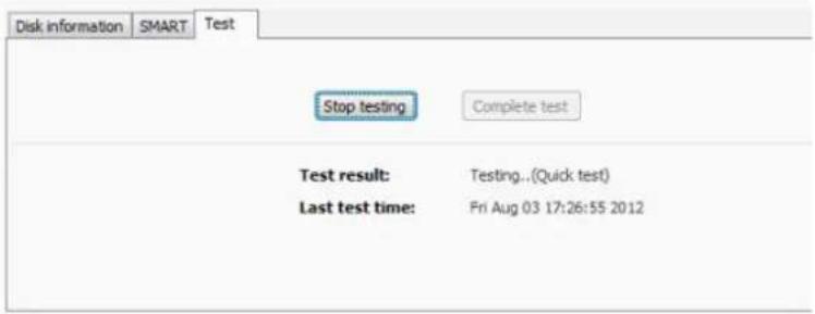
Network Status
This window provides a glimpse of the system two GbE ports including the network type, IP address, subnet, and gateway values.

Control Center
Disk Status
Network Status
System Status

Type:
DHCP
IP address:
192,168.4,143
Subnet mask:
255.255.255.0
Default gateway:
192.168.4.1


Type:
DHCP
IP address:
192,168.4.140
Subnet mask:
255,255,255.0
Default gateway:
192.168.4.1
System Status
System Status states the current working status and system time.
Network Status
System Status
Model: ND8401
Service: running
Date/Time: 2012/12/28 17:19:38
License: 16
Version: 1.7.1.4
Appendix Rebuilding a RAID Volume
If a drive fails, the failure will be indicated by the system fault LED or the Disk Status panel. If a disk drive fails in a RAID5 volume, first locate the faulty drive in the Disk Status panel, remove the faulty drive with a drive of the same capacity and rotation speed.
You should be prompted by the message if a hard drive fails or was removed. An incorrect or abrupt shutdown of the system may also force the system to rebuild a RAID volume. Data may not have all been properly distributed to hard drives when inappropriately shut down.

Note that you must carefully identify the faulty drive. Replacing the wrong drive from a RAID5 volume will result in losing 2 member drives. If a RAID5 volume loses 2 members, all data will be lost on that volume.
![VIVOTEK Control Center Disk Status Network Status System Status Logical volume: Physical disk Model Capacity SHART State Temperature 1 ST3160811AS 160 GB PASSED ArrayMember 40°C (104.0°F) 2 ST3160811AS 160 GB PASSED ArrayMember 42°C (107.6°F) 3 ST3160811AS 160 GB PAUSED ArrayMember 33°C (91.4°F) Disk information SHART Test Model family: Seagate Barracuda 7200.9 Model number: ST3160811AS Serial number: 9PT0360E Firmware version: 2.AAE Capacity: 160,041,885,696 bytes [160 GB] ATA version: 7 ATA standard: Exact ATA specification draft version not indicated](/content/2026/06/1279498/images/b75ad35c16df1d5692ba1ed417c5e8c2dc807bd704bb9e78cfe5fc04d2569d7c.jpg)
Once you replace the faulty drive with a new one, an automatic rebuild will begin, and its progress will be indicated by a status bar as shown below. The process will take hours depending on the sizes of your disk drives, e.g., 8 hours if using 2TB drives in a RAID5 volume.
If using a RAID5 volume, the recording task will be halted during the rebuild process. Recording will continue if using storage volumes in other RAID levels.

Control Center
Disk Status
Network Status
System Status

Setup Wizard

LiveClient

Playback

Service

Import / Export Only

Installation Wizard 2

Shepherd

Upgrade

File Manager
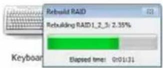
Technical Specifications
Technical Specifications
System
CPU: Dual-core Intel ^® processor
RAM: 4GB DDRIII
OS: Windows 7 embedded
Channels
16-CH selectable
Storage
4 x 3.5" HDD, up to 12TB
4 x hol-swappable & lockable hard disk tray
HDD S.M.A.R.T. (Self-Monitoring Analysis and Reporting Technology)
RAID 0, 1, 5, 10
External eSATA storage
Connectors
1 x VGA for Full HD local display
2 x Gigabit RJ45 Ethernet port
6 x USB 2.0 pod
1×RS232
1 x eSATA
1 x MIC in and line in
1 x line out
Camera Compatibility
Full integration with VIVOTEK network cameras
Integration with ONVIF network cameras (by project)
Easy Setup
Setup Wizard for network/HDD/camera easy setup
IV2 for search internal camera
Shepherd for duplicating the camera's configuration to multiple cameras
Networking
IPv4, TCP/IP, HTTP, RTSP/RTP/RTCP, IGMP, SMTP, DHCP, NTP, DNS, DDNS
Recording
Throughput max. 96 Mbps
Recording policy: scheduled (event/continuous modes) and manual recording
Video compression: H.264/MJPEG/MPEG-4
Audio compression: AMR/G.711/AAC
Resolution: Up to 5-Megapixel recording
Format: 3GPP
Auto recycling, buffer size setting, time setting
Activity adaptive recording
Export
Format: AVI/3GPP/EXE
Local LiveClient
Display layout: 1X1, 2X2, 3X3, 4X4, 1+5, 1+12
Rotate
Snapshot
Two way audio control
PIP video control
Stream selectable
Set DO control
Video enhancement
PanTilbZoom control of VIVOTEK cameras
Preset location
Auto pan/patrol
Event popup windows
Instant event notification
Display performance:
MJPEG: 16-CH, 30 fps @ CIF
MPEG4: 16-CH, 30 fps @ CIF or 2-CH, 30 fps @ 1080P
H.264; 7-CH, 30 fps @ CIF or 1-CH, 30 fps @ 1080P
Auto stream size
Local Playback
Display layout: 1X1
Playback mode: play, pause, stop, next/frame, next/previous, speed control
Search mode: browsing, time, event, bookmark
Graphical timeline
Snapshot
Bookmark design
- PIP VIDEO CONTROL
Video enhancement
[Unreadable]
Remote Liveview
Display layout: 1X1, 2X2, 3X3, 4X4, 1+5, 1+12
Snapshot
Pan/Tilt/Zoom control of VIVOTEK cameras
Simple camera and recording settings
Remote Playback
Display layout: 1X1
Playback mode: play, pause, stop, speed control
Search mode: browsing, event
Graphical timeline
Event/Action Management
Trigger source: motion, temperature, tampering, DIO, IR, PIR, IVA, video lost, recording error,
recording status, substation connection status, storage connection status, storage capacity status,
License status, network status or memory status Actions: email start recording move to the project position, set DO, CSM short message & send
CGI command
Security
5 levels of user roles
Multi-level user access with password protection
Device buzzer notification (HDD/network)
Backup
Manual'scheduled backup
Mobile APP Support
VIVOTEK Viewer (iOS/Android)
Dimension
204 mm (W) x 330 mm (D) x 216 mm (H)
Weight
Net: 5.24 kg (without HHD)
LED Indicator
1 x Power statu
1 x HDD status
Power
Input: AC 100-240 V, 50-60 Hz
Power consumption: max. 58 W
Approvals
CE, FCC Class B, VCCI, C-Tick
Operating Environments
Temperature: 0°C - 40°C
Humidity: 20%-95% RH
Warranty
24 months
Language
English, French, German, Italian, Spanish, Traditional Chinese, Simplified Chinese, Japanese,
Portuguese, Czech
Included Accessories
CD content: user's manual, quick installation guide, installation wizard 2. LiveClient (remote),
Playback (remote)
Others: quick installation guide, warranty card, power cord
Application
Multi-site Chain Stores
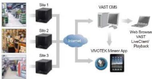
flowchart
graph TD
    A["Site 1"] --> B["Internet"]
    C["Site 2"] --> B
    D["Site 3"] --> B
    B --> E["VAST CMS"]
    E --> F["Web Browser VAST LiveClient/Playback"]
    B --> G["VIVOTEK Miewer App"]
Dimensions
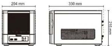
Part No.
ND8401, USA 100091100G ND8401, UKB 100091130G
ND8401, AUN 100091110G ND8401, Mexico 100091200G
ND8401, EU 100091120G
All specifications are subject to change without notice. Copyright © 2013 VIVOTEK INC. All rights reserved.
Distributed by:

VIVOTEK INC.
8F, No.192, Len-Chang Rd., Chung-Ho, New Taipei City, 235, Taiwan, R.O.C.
T: -886-2-82455252 F: +855-2-82455532 E: sales@vivptek.com
VIVOTEK USA, INC.
2050 Ringwood Avenue, San Jose, CA 95131
T: 408-773-9526 | F: 408-773-9298 | E: as.eusa@vxtek.com
Ver 1.0
- ND8401 Network Video Recorder
- User's Manual
- Table of Contents
- Chapter One Hardware Installation and Initial Configuration 10
- Chapter Two NVR LiveClient Configuration 24
- VAST Server 26
- LiveClient Configuration 27
- How to Manage Devices (Cameras) 37
- Revision History
- Read Before Use
- Package Contents
- NOTE:
- Symbols and Statements in this Document
- Chapter One Hardware Installation and Initial Configuration
- Introducing ND8401 Network Video Recorder
- Special Features
- Physical Description
- IMPORTANT:
- Hardware Installation
- Interface Connections
- Network Deployment
- Initial Configuration
- Model Capacity
- Ready to Use
- 3-2. Click on the Search button.
- Address Port Model MAC
- NVR Desktop Elements
- Menu Bar
- Alarm Sound
- Chapter Two NVR LiveClient Configuration
- i Information:
- VAST LiveClient Functionality
- VAST Server
- Activating the VAST Server
- How to Stop/Reboot the Server
- LiveClient Configuration
- Opening the LiveClient Interface and Logging in
- Quick Access Bar
- Icon Function Description
- Live Video Monitoring Window
- Camera Control Panel
- Two Way Audio Control Panel
- Event Window
- Instant Playback (on Remote LiveClient)
- Instant Replay (on Remote LiveClient)
- Prerequisites for Instant Replay:
- How to Use:
- Audio Control
- How to Manage Devices (Cameras)
- Insert Cameras
- e. Configure Recording Settings:
- Enable SVC
- Update Devices
- Delete Devices from the Station
- ■ Delete a device:
- ■ Delete more than one device at a time:
- Address Port Model Name
- Batch Insert Cameras
- Name Address Port Model MAC Status
- Address Port Model MAC
- Camera Configuration
- ■ FOV (Field of View)
- ■ Video
- ■ Audio
- ■ Remote Focus
- ■ NTP Settings
- View Live Videos
- Dual / Multiple Streams
- Fisheye Display Modes
- 2P (2 Panoramic) Display mode:
- 2P (Panoramic) Mode Screen Control
- 103R (One Original & 3 Regional) Display mode:
- PTZ Mouse Control
- Refresh
- Streaming Server
- Get Public IP
- Camera Settings
- Remove Live Video from the Video Monitoring Window
- How to Change the VAST LiveClient Layout
- Changing the Layout of the Live Video Monitoring Window
- Switch Video Channels
- Configure Layout Mode
- Rotating Video Pages
- Edit Layout
- Maximize the Live Video Monitoring Window
- How to Manage Stations
- Relay Settings
- How to Manage User Accounts
- Manage a User Account
- Add a New User Account
- Permission of the User Account
- Delete the User Account
- How to Set up Association Management
- Association Management
- How to Set up Event Management
- Event Management
- How to Configure the Station General Settings
- Server Settings
- Log Settings
- Reboot Settings
- How to Configure Station Network Settings
- Port Settings
- UPnP Settings
- Proxy Settings
- Web Access Settings
- How to Edit Recording Stoage
- Recording Storage Settings
- Default Storage Group Settings
- Add New Storage Group(s)
- How to Edit Recording Schedules
- Edit Schedule List
- Add Schedules
- Rename Schedules
- Delete Schedules
- Load/Save Schedule Templates
- Edit Camera List
- Edit Time Frame List
- Add New Time Frames
- Recording Settings
- The Concept of Repeat Frequency
- Repeat Frequency: Daily Setting
- Set up daily time segments
- Add time segments: Choose either step 1 or step 2 to set up
- Delete time segments: Choose either step 1 or step 2 to set up
- Set up applicable period of time
- Set up repeat time interval
- Repeat Frequency: Weekly Setting (Day-based)
- Set up applicable days within a week
- Repeat Frequency: Weekly Setting (Periods in a week)
- Set up time segments within a week
- Repeat Frequency: Monthly Setting (Day-based)
- Set up applicable date(s) of a month/ day(s) of a week
- Repeat by date(s) of a month:
- Repeat by day(s) of a week:
- Repeat Frequency: Yearly Setting (Day-based)
- Set up applicable date(s) of a year/ day(s) of a week
- Repeat by date(s) of a year:
- How to Manually Begin /Stop Recording
- How to Edit Scheduled Backup Settings
- Select Backup Source
- Setup Backup Schedule
- Select Backup Target
- Other Options
- How to Configure Station Server Settings
- DDNS Settings
- Network Storage Server Settings
- SMTP Settings
- How to Use the Talk Panel
- Add a Camera to the Talk Panel
- Remove a Camera from the Talk Panel
- ■ Remove a camera
- ■ Remove all cameras
- How to Configure E-map Settings
- Upload an E-map
- E-map Settings Page (View Mode)
- Status Panel
- Device Management
- Live View Dialog Settings
- Open Live View Dialog
- Send to Single View
- E-map Link
- How to Configure Client Settings
- Snapshot Settings
- Taking a Snapshot
- Type 1: Record to EXE
- Type 2: Record to 3GP
- Type 3: Record to AVI
- Record an EXE/3GP/AVI File
- Built-in Media Player--EXE
- Tips
- View Settings
- Date and Time Format
- Video Display Mode
- Font Settings
- General Settings
- System Settings
- Event Settings
- Rotation Settings
- Display Settings
- WARNING:
- Joystick Settings
- Enable Joystick
- Buttons Configuration
- PTZ/ E-PTZ Function
- How to Use PiP (Picture-in-Picture)
- Enable PiP
- Global View
- ROI (Region of Interest)
- Digital Zoom In
- Snapshot Zoomed In Image
- PiP Settings
- How to Configure Video Enhancement
- Basic Image Adjustment
- Defog
- Apply a Preset Defog Profile
- Create a New Defog Profile
- How to Search for a Device on the Hierarchical Device Tree
- How to Lock LiveClient for Security Concerns
- How to Log out from the VAST Server
- How to Exit VAST LiveClient
- Lauch Playback
- Second View
- Chapter Three NVR Playback Configuration
- Activating VAST Playback and Logging in to a Server
- Recorded Video Playback Window
- Query Panel-- Browsing Page
- Query Panel--Time Search Page
- How to Change the Playback Layout
- Changing the Layout of the Recorded Video Playback Window
- Layout Mode
- Maximize the Recorded Video Playback Window
- How to Backup Recorded Video
- How to View Backup Files
- Model-specific Functions (FE Series Fisheye)
- How to Search for a Video Clip Taken at a Specific Time
- How to Add a Bookmark
- How to Search for Events
- Select Event Category
- Event Category- All Events
- Event Category- All Motion Events
- Event Category- All IVA events
- Event Category- All DI Events
- Event Category- Named DI Events
- Start Event Search
- Backup the Event Videos
- How to Search for a Bookmark
- How to Search Logs
- Select Log Category/Log Type/Log Level
- Log Categories Log Levels Log Types
- Event Log High
- Search All Local Logs
- Search Login History
- Search Login Activities
- Export Settings
- Export an EXE/3GP/AVI File
- How to Search for a Device on the Hierarchical Management Tree
- How to Lock VAST Playback for Security Concerns
- How to Exit VAST Playback
- Chapter Four Auxiliary Utilities
- Service
- Import and Export Utility
- Installation Wizard 2
- Shepherd
- Upgrade
- File Manager
- Keyboard
- Disk Status
- Network Status
- System Status
- Appendix Rebuilding a RAID Volume
- Technical Specifications
- System
- Channels
- Storage
- Connectors
- Camera Compatibility
- Easy Setup
- Networking
- Recording
- Export
- Local LiveClient
- Local Playback
- Remote Liveview
- Remote Playback
- Event/Action Management
- Security
- Backup
- Mobile APP Support
- Dimension
- Weight
- LED Indicator
- Power
- Approvals
- Operating Environments
- Warranty
- Language
- Included Accessories
- Application
- Dimensions
- Part No.
- VIVOTEK INC.
- VIVOTEK USA, INC.
Brand : Vivotek
Model : ND8401
Category : Voice recorder