
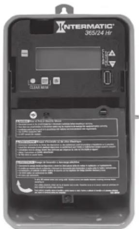
ET2115CP - Switch INTERMATIC - Free user manual and instructions
Find the device manual for free ET2115CP INTERMATIC in PDF.


| Product Type | Electronic 24-Hour Time Switch |
| Model | ET2115CP |
| Enclosure | Rainproof Type 3R, indoor/outdoor, lockable plastic |
| Input Voltage | 120-277 VAC, 60 Hz (auto-voltage, no jumpers) |
| Power Consumption | 3 W max |
| Switch Configuration | SPDT x 1 (Normally Open and Normally Closed) |
| Switch Ratings (Resistive) | 20 A at 120-240 VAC (NO), 10 A at 120-240 VAC (NC) |
| Switch Ratings (Inductive) | 20 A at 120-240 VAC (NO), 10 A at 120-240 VAC (NC) |
| Switch Ratings (Motor) | 1 HP at 120 VAC (NO), 1/4 HP at 120 VAC (NC) |
| Number of Events | Up to 48 ON and 48 OFF (96 total) |
| Clock Backup | 100-hour Supercapacitor |
| Wire Size | #14-#8 AWG copper, rated 105°C min |
| Weight | 2.5 lb (1.1 kg) |
| Operating Modes | Auto, Energy Saver, Manual |
| Daylight Saving Time | Programmable (US2007, MX1986, or Custom) |
| Holiday Programming | Up to 50 holiday blocks with start/end dates and events |
| USB Functionality | Read and write schedules via USB memory stick |
| Minimum ON/OFF Time | 1 minute |
| Maximum ON/OFF Time | Indefinite |
| Knockouts | Combination 1/2-3/4 in., 1 rear, 1 each side, 2 bottom |
Frequently Asked Questions - ET2115CP INTERMATIC
User questions about ET2115CP INTERMATIC
0 question about this device. Answer the ones you know or ask your own.
Ask a new question about this device
Download the instructions for your Switch in PDF format for free! Find your manual ET2115CP - INTERMATIC and take your electronic device back in hand. On this page are published all the documents necessary for the use of your device. ET2115CP by INTERMATIC.
USER MANUAL ET2115CP INTERMATIC
MODELS ET2115C, ET2115CR, ET2115CP Installation and Setup Instructions
WARNING Risk of Fire or Electric Shock
- Disconnect power at the circuit breaker(s) or disconnect switch(es) before installing or servicing.
- More than one circuit breaker or disconnect switch may be required to de-energize the equipment before servicing.
- For plastic enclosures, bonding between conduit connections is not automatic and must be provided as part of the installation.
• Installation and/or wiring must be in accordance with National and Local Electrical Code requirements. - Use #14-#8 AWG wires, rated at least 105°C - COPPER conductors ONLY.
- If the power disconnect point is out of sight, lock it in the OFF position and tag it to prevent unexpected application power.
- Make sure there is no wire insulation under the terminal plate on the time switch connector. Firmly tighten terminal screws.
- For outdoor locations or wet locations (rain-tight), conduit hubs that comply with requirements of the UL514B (standard for fitting conduit and outlet boxes) are to be used.
- Do not remove insulator that is covering terminals.
- Do NOT exceed maximum current carrying capacity.
- KEEP DOOR CLOSED AT ALL TIMES when not servicing.
NOTICE
- Do NOT touch circuit board components, contact can create a static discharge, which can damage these electronic components.
Description
This document explains the setup and configuration of the Intermatic ET2115 1-Circuit Electronic 24-Hour Time Switch. The ET2115 time switch automatically switches loads according to the entered daily schedule. The time switch can support up to 48 fixed ON and 48 fixed OFF events (96 total).
The time switch features an LCD and panel-mounted control buttons to set, review, and monitor the time switch functions, including setting date and time, schedule creation, enabling or disabling Daylight Saving Time (DST) and configuring DST switchover dates. Follow these instructions to complete the installation and programming of the ET2115 time switch.
Wiring Diagram
Initial Setup
The following sections provide instructions for the initial setup of the time switch.Programming Overview
The steps to program the time switch include setting the current date, time, fixed events, DST, and holiday events, setting the time switch's operation to AUTO mode, ENERGY SAVER mode or MANUAL mode (only MANUAL mode will appear if there are no scheduled events) and read or write an event schedule from a USB memory stick. NOTE: If the time switch is left inactive for five minutes in a programming mode, it will return to the AUTO mode screen (AUTO icon turned on). If no scheduled events are programmed, the time switch will return to MANUAL mode. If the date has not yet been entered, the time switch will go to the Enter Date Mode.Setting Date
Follow this procedure below to set the date and time in the time switch. NOTE: If necessary, hold + or - to scroll through the digits rapidly. 1. Press MODE to scroll through the mode selections until SET and DATE icons appear at the top of the display. The month flashes. 2. Press + or - to select the current month and then press ENTER/NEXT. The day of the month flashes. 3. Press + or - to select the current day of the month, and then press ENTER/NEXT. The year flashes. 4. Press + or - to enter the current year, and press ENTER/NEXT. The month will flash again. 5. Press MODE to move to the next mode selection.Setting Time
Follow the procedure below to set the time in the time switch. NOTE: If necessary, hold + or - to scroll through the digits rapidly. 1. Press MODE to advance to the Set Clock mode selection if this selection is not already active. The SET and TIME icons appear on the display and a flashing 12:00 AM appears (if clock has not been set). 2. Press + or - to select the current time. NOTE: Seconds can be set to 00 by pressing ENTER/NEXT. 3. Press MODE to save the time and move to the Enable Daylight Saving Time mode selection. NOTE: If the time switch programming data is to be read from a USB memory stick, refer to the "Read Time Switch Program Data..." section in these instructions.Enable/Disable Daylight Saving Time and Setting Daylight Saving Time Rule
Configure the time switch to automatically adjust for Daylight Saving Time (DST). If DST does not apply to your region, disable the option as directed in this procedure. Follow this procedure to enable/disable the Daylight Saving Time feature, and if applicable, set the DST rule. 1. Press MODE to advance to the Set DST mode selection if this selection is not already active. The SET and DST icons appear on the display. 2. Press + to display ON (enable DST) or press - to display OFF (disable DST) and then press ENTER/NEXT to save.| If DST is Then | |
| Enabled Go to step 3. | |
| Disabled Press MODE to save and exit. | The procedure is complete. |
| If you select Then | |
| US2007 or MX1986 | Go to step 8. NOTE: To view the start and end dates for a DST rule, press ENTER/NEXT to scroll through the dates and then press MODE. |
| Custom | Press ENTER/NEXT. The screen displays a flashing MAR and 2ND. Go to step 4. |
Setting Fixed Timed Events
Access the Fixed ON/OFF screen to set fixed switching times. Odd-numbered events are for ON switching and even-numbered events are for OFF switching. Follow these steps to set fixed time events (if no fixed events need to be set press MODE to move to the next mode selection): 1. Press MODE to advance until SET FIXED ON/OFF EVENTS and ON@ icons appear on the display (if this selection is not already active). The Event Number and LOAD icon are also displayed. Press ENTER/NEXT if this fixed on event is not needed, go to step 5. 2. If an event is not set the time display will show - - - . 3. Press + or - to set the time for the fixed event to occur. 4. Press ENTER/NEXT to save. 5. The Event Number increments and the SET FIXED ON/OFF EVENTS and OFF@ icons are displayed. Press ENTER/NEXT if this fixed off event is not needed, go to step 9. 6. If an event is not set the time display will show - - - . 7. Press + or - to set the time for the fixed event to occur. 8. Press ENTER/NEXT to save. 9. The Event Number increments and the SET FIXED ON/OFF EVENTS and ON@ icons are displayed. Press ENTER/NEXT if this fixed off event is not needed.| If Then | |
| Another fixed event needs to be set Return to step 2. | |
| All the events are set Press MODE to save and exit. The procedure is complete. | |
Setting Holidays
There are 50 Holiday blocks that can be programmed along with a single schedule for each block. For each block there will be a start date and an end date. Within each block one scheduled "on" event and one "off" event can be programmed. Holidays are recognized by an H on the display. During the dates chosen, the relays will remain in the "OFF" state and HOLldy will show on the display. NOTE: During holiday blocks only programmed holiday events will trigger relay operations. To program holiday blocks follow these guidelines: 1. Press MODE to advance until the SET, DATE and ON@ icons appear on the display if this selection is not already active. A holiday Number is also displayed on the right side of the display. 2. The time display will flash - - - - and also show 1H. 3. Press the + or - buttons to choose the month that the holiday will start. 4. Press ENTER/NEXT and the day of the month, the 1, will flash. 5. Press the + or - buttons to choose the day that the holiday will start. 6. Press ENTER/NEXT and the OFF@ icon is displayed. 7. The time display will flash - - - - and also show 1H. 8. Press the + or - buttons to choose the month that the holiday will end. 9. Press the ENTER/NEXT and the day of the month, the 1, will flash. 10. Press the + or - buttons to choose the day that the holiday will end. 11. Press ENTER/NEXT and the SET ON@ ON/OFF EVENTS icons are displayed. (Press ENTER/NEXT twice to skip setting an event during the holiday period in which case the circuit will remain off.) 12. The time display shows - - - - and event number 1 is also displayed on the right side of the display. 13. Press the + or - buttons to set the time for this holiday event to start. 14. Press ENTER/NEXT and the OFF@ icon is displayed. 15. The time display shows - - - - and event number 2 is also displayed on the right side of the display. 16. Press the + or - buttons to set the time for this holiday event to end. 17. Press ENTER/NEXT and the SET, DATE and ON@ icons appear on the display. The next holiday number is displayed on the right side of the display.| If Then | |
| Another holiday period needs to be set | Return to step 2. |
| All the events are set Press MODE to save and exit. The procedure is complete. | |
Setting Operating Mode
The time switch can be set to one of three operating modes: AUTO (default setting), ENERGY SAVER or MANUAL. Once operating mode is selected the time switch setup is complete. NOTE: If no scheduled events are programmed, only MANUAL mode is available. In AUTO mode, the time switch follows the user-programmed events and the circuit turns ON and OFF at the programmed time(s). • To place in AUTO mode, press MODE and advance until the AUTO icon appears on the display. - In AUTO mode, pressing an ON/OFF button temporarily overrides the current state of the circuit. The time switch returns to the normal schedule at the next programmed event. In ENERGY SAVER mode the time switch operates similarly to AUTO mode with the following exceptions: \- The ON/OFF buttons manually activate the circuit for only a 2-hour period. \- When a 2-hour period is active, pressing ON/OFF extends the active period by 2 hours. \- Pressing and holding (for 3 seconds) the ON/OFF button will turn OFF the circuit. \- The ON/OFF buttons manually activate the circuit for only a 2-hour period. - When a 2-hour period is active, pressing ON/OFF extends the active period by 2 hours. - Pressing and holding (for 3 seconds) the ON/OFF button will turn OFF the circuit. For ENERGY SAVER mode, press the MODE button until the AUTO icon on the display flashes. In MANUAL mode the time switch does not follow any programmed events and only activates the circuit when the ON/OFF button is pressed. \- For MANUAL mode, press the MODE button until the MANUAL icon appears on the display.Deleting (Clearing) an Event
Fixed events can be deleted from the time switch. If you need to delete an event, follow this procedure. 1. If necessary, press MODE to scroll through the different mode selections until SET FIXED ON/OFF EVENTS appear on the display. 2. Press ENTER/NEXT as necessary to scroll through the scheduled events until you see the event you want to delete. 3. Press + and - at the same time until the display shows --:-- --. This indicates the event is erased. 4. If necessary, press ENTER/NEXT to scroll through the other configured events. 5. Press MODE to save the changes and exit.Clearing Time Switch Memory
During a “Clear Time Switch Memory” operation, the time switch resets all programmed settings to their factory default value. The following occurs: - After a brief period of time the time switch model number appears, followed by the USB Boot Loader version, EE Boot Loader version, the firmware revision and finally the Reset Reason Code. - MEMCLR is displayed followed by DONE when the operation is completed. To perform a "Clear Time Switch Memory" operation do the following: 1. Press and hold ENTER/NEXT. 2. While pressing and holding ENTER/NEXT, press and release the RESET (round) button. Do not release ENTER/NEXT. 3. Continue to press and hold ENTER/NEXT until MEM CLEAR then DONE briefly appears.Writing Time Switch Program Data to a USB Memory Stick
The time switch has the capability to copy its programmed data (event schedules, holidays, output configuration, DST on/off setting, DST rule setting and geographical location) to a USB memory stick. Follow these steps to transfer all programming from the time switch to a USB memory stick: 1. Press MODE to advance until wr USb is displayed. 2. Press ENTER and insUSb is displayed. 3. Insert a USB memory stick into the USB port on the front face of the time switch. 4. SCHEdL 01 is displayed. Press + or - to increment/decrement the schedule number on the display (01-99). 5. When the desired number is displayed, press ENTER and this will write the data file to the USB memory stick. The file name will be SCHEDLx x.T XT where xx is the schedule number selected in the previous step. 6. After the file is written REMOVE is shown on the display. 7. Remove the USB memory stick and the time switch will advance to the next mode selection. If all procedures are completed, press MODE repeatedly until back to the operating mode selection (AUTO, ENERGY SAVER, MANUAL).Reading Time Switch Program Data from a USB Memory Stick
The time switch has the capability to read program data (event schedules, holidays, output configuration, DST on/off setting, DST rule setting and geographical location) from a USB memory stick. Follow these steps to transfer all programming from a USB memory stick to the time switch: 1. Press MODE to advance until rd USb is displayed. 2. Insert a USB memory stick containing the desired data file into the USB port on the front face of the time switch. 3. Press ENTER and insUSb is briefly displayed. 4. SCHEdL.xx is displayed where xx is the first data file number found on the USB memory stick. 5. Press + or - to scroll through the data files on the USB memory stick (if more than one file is stored on this stick). 6. When the desired number is displayed, press ENTER and the time switch will read the data file from the USB memory stick. 7. After the file is read into the time switch, DONE is briefly shown on the display followed by REMOVE. 8. Remove the USB memory stick and the time switch will advance to the next mode selection. If all procedures are completed, press MODE repeatedly until back to the operating mode selection (AUTO, ENERGY SAVER, MANUAL).USB error codes
If a problem occurs when attempting to perform a USB read or write operation the time switch will show an error code on the display. Following is a description of the different error codes: OPFILE Er File could not be created on the USB memory stick (stick may be write protected or corrupted) wrFILE Er Program data could not be written to the USB memory stick (stick may be full) oPFILE ER File could not be opened for reading from the USB memory stick rdFILE Er File could not be read from the USB memory stick MSDH Er USB device is not a memory type device FATFS Er Fat file system error indicating the memory stick contains a data format that is incompatible with the time switch DEVICE Er USB memory stick is defective shCrct Er The power supply for USB port on the time switch is not functioningSpecifications
Input Voltage: 120-277 VAC, 60 Hz Power Consumption: 3 W MAX Switch Configuration: SPDT x 1. See wiring diagrams in this manual. Switch Ratings:| Rating NO | Rating NC | Load Type | Voltage | Frequency |
| 20 A | 10 A | Resistive | 120-240 VAC | 60 Hz |
| 20 A | 10 A | Resistive | 28 VDC | - |
| 20 A | 10 A | Inductive | 120-240 VAC | 60 Hz |
| 20 A | 3 A | Magnetic Ballast | 120-277 VAC | 60 Hz |
| 10 A | - | Electronic Ballast | 120/277 VAC | 60 Hz |
| 1 HP | 1/4 HP | Motor | 120 VAC | 60 Hz |
| 2 HP | 1/2 HP | Motor | 240 VAC | 60 Hz |
LIMITED WARRANTY
Warranty service is available by either (a) returning the product to the dealer from whom the unit was purchased or (b) completing a warranty claim online at www.intermatic.com. This warranty is made by: Intermatic Incorporated, Customer Service 1950 Innovation Way, Suite 300, Libertyville, IL 60048. For warranty service go to: http://www.intermatic.com or call 815-675-7000. INTERMATIC INCORPORATED 1950 Innovation Way, Suite 300 LIBERTYVILLE, ILLINOIS 60048 www.intermatic.com- MODELS ET2115C, ET2115CR, ET2115CP Installation and Setup Instructions
- WARNING Risk of Fire or Electric Shock
- NOTICE
- Description
- Federal Communications Commission (FCC) Notice for ET2000 Series Time Switches
- Installation
- Wiring Diagram
- Initial Setup
- Programming Overview
- Setting Date
- Setting Time
- Enable/Disable Daylight Saving Time and Setting Daylight Saving Time Rule
- Setting Fixed Timed Events
- Setting Holidays
- Setting Operating Mode
- Deleting (Clearing) an Event
- Clearing Time Switch Memory
- Writing Time Switch Program Data to a USB Memory Stick
- Reading Time Switch Program Data from a USB Memory Stick
- USB error codes
- Specifications
- LIMITED WARRANTY
Brand : INTERMATIC
Model : ET2115CP
Category : Switch