SLT - Sound Level Meter PCE Instruments - Free user manual and instructions
Find the device manual for free SLT PCE Instruments in PDF.


| Product Type | Sound Level Meter (with transmitter and digital display) |
| Brand | PCE Instruments |
| Model | SLT |
| Measuring Range | 30 ... 130 dB (three switchable ranges) |
| Resolution | 0.1 dB |
| Accuracy | ±1.5 dB |
| Frequency Weighting | A |
| Standard | IEC 61672 Class II |
| Microphone | 1/2" precision electret microphone |
| Transmitter Housing | ABS plastic |
| Transmitter Power Supply | 90 ... 260 VAC or 24 VDC (max. 1.5 A) |
| Transmitter Output | 4 ... 20 mA |
| Transmitter Protection Class | IP 50 |
| Display Input | 4 ... 20 mA (from transmitter) |
| Display Range | -1999 ... 9999 (user-selectable 1-3 decimal places) |
| Display Relay Outputs | Control relay: 0.5 A / 240 VAC; Alarm relay: 0.5 A / 240 VAC |
| Display Power Supply | 90 ... 260 VAC / 50 ... 60 Hz |
| Display Protection Class | IP 60 |
| Display Panel Cutout | 92 (+0.8) mm x 45 (+0.5) mm (DIN) |
| Display Weight | Approx. 250 g / 0.56 lb |
| Cable Length (Sensor to Transmitter) | 1.5 m |
| Environmental Conditions | 0 ... +50 °C / 32 ... 122 °F, max. 80 % RH (non-condensing) |
| Calibration | Adjustable via grub screw on transmitter (SPAN potentiometer) |
| Accessories Included | Wall bracket (screwable) |
| Maintenance & Cleaning | Clean with damp cloth and pH-neutral cleaner; do not use abrasives or solvents. |
| Safety Notes | Read manual before use; use by qualified personnel; avoid shocks, extreme temperatures, humidity; do not use in explosive atmospheres. |
Frequently Asked Questions - SLT PCE Instruments
User questions about SLT PCE Instruments
0 question about this device. Answer the ones you know or ask your own.
Ask a new question about this device
Download the instructions for your Sound Level Meter in PDF format for free! Find your manual SLT - PCE Instruments and take your electronic device back in hand. On this page are published all the documents necessary for the use of your device. SLT by PCE Instruments.
USER MANUAL SLT PCE Instruments
natural_image
Exterior view of a sound level indicator (PCB) device with digital display and control buttons (no readable text beyond labels)User Manual
PCE-SLT Sound Level Meter (Including Transmitter PCE-SLT-TRM)
User manuals in various languages (français, italiano, español, português, nederlands, türk, polski, русский, 中文) can be found by using our product search on: www.pce-instruments.com
Last change: 13 August 2024
v1.0
Contents
1 Safety notes....1
2 Specifications.... 2
3 Dimensions.... 3
4 Description transmitter .... 4
5 Display description.... 5
6 Initial commissioning 7
6.1 Connecting the transmitter 7
6.2 Connecting the display....7
7 Set measurement ranges 7
8 Calibration 7
9 Alarm setting (control) 7
10 Advanced menu 8
10.1 Decimal point shift....8
10.2 4 mA Parameter....8
10.3 20 mA parameter 8
10.4 Filter function 8
10.5 Hysteresis for the control message....8
10.6 Hysteresis for the alarm function 9
10.7 Offset 9
10.8 Gain setting....9
10.9 Set RS232 unit....10
11 RS232....11
11.1 RS232 settings....11
11.2 RS232 protocol....12
12 Reset system.... 12
13 Contact.... 12
14 Disposal 12
1 Safety notes
Please read this manual carefully and completely before you use the device for the first time. The device may only be used by qualified personnel and repaired by PCE Instruments personnel. Damage or injuries caused by non-observance of the manual are excluded from our liability and not covered by our warranty.
- The device must only be used as described in this instruction manual. If used otherwise, this can cause dangerous situations for the user and damage to the meter.
- The instrument may only be used if the environmental conditions (temperature, relative humidity, ...) are within the ranges stated in the technical specifications. Do not expose the device to extreme temperatures, direct sunlight, extreme humidity or moisture.
- Do not expose the device to shocks or strong vibrations.
• The case should only be opened by qualified PCE Instruments personnel.
- Never use the instrument when your hands are wet.
- You must not make any technical changes to the device.
- The appliance should only be cleaned with a damp cloth. Use only pH-neutral cleaner, no abrasives or solvents.
• The device must only be used with accessories from PCE Instruments or equivalent.
- Before each use, inspect the case for visible damage. If any damage is visible, do not use the device.
- Do not use the instrument in explosive atmospheres.
- The measurement range as stated in the specifications must not be exceeded under any circumstances.
- Non-observance of the safety notes can cause damage to the device and injuries to the user.
We do not assume liability for printing errors or any other mistakes in this manual.
We expressly point to our general guarantee terms which can be found in our general terms of business.
2 Specifications
| Sound sensor | |
| Measuring range | 30 ... 130 dB in three ranges |
| Resolution | 0.1 dB |
| Measuring accuracy | ±1.5 dB |
| Frequency weighting | A |
| Power supply | via transmitter |
| Cable length | 1.5 m |
| Wall bracket | screwable (included in the scope of delivery) |
| Envioronmental conditions | max. 80 % RH / 0 ... +50 °C / 32 ... 122 °F |
| Microphone | 1/2" precision electret microphone |
| Standard | IEC 61672 Class II |
| Transmitter | |
| Housing | ABS plastic |
| Power supply (depending on model) | 90 ... 260 VAC24 V DC (max. 1,5 A) |
| Calibration | adjustable via grub screw |
| Output | 4 ... 20 mA |
| Protection class | IP 50 |
| Environmental conditions | max. 80 % RH / 0 ... +50 °C / 32 ... 122 °F |
| Digital display | |
| Input signal from transmitter | 4 ... 20 mA |
| Display | -1999 ... 9999 (1 ... 3 decimal places, depending on measured value / user-selectable) |
| Programming data (decimal place, limit value...) | are stored in the device |
| Control output | relay output: 0.5 A / 240 VAC |
| Alarm output | relay output: 0.5 A / 240 VAC |
| Power supply | 90 ... 260 ACV / 50 ... 60 Hz |
| Dimensions / panel cut-out according to DIN | 92 (+ 0.8) mm x 45 (+ 0.5) mm |
| Weight | approx. 250 g / 0.56 lb |
| Envioronmental conditions | max. 80 % RH / 0 ... +50 °C / 32 ... 122 °F |
| Protection class | IP 60 |
3 Dimensions
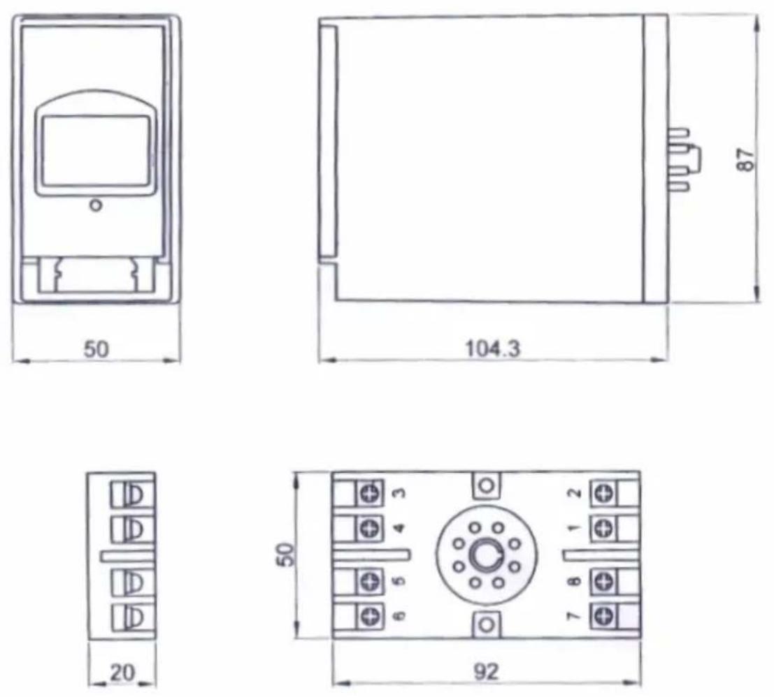
4 Description transmitter
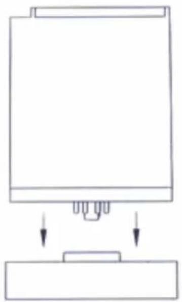
natural_image
Simple line drawing of a mechanical component with two downward arrows indicating force or movement (no text or symbols)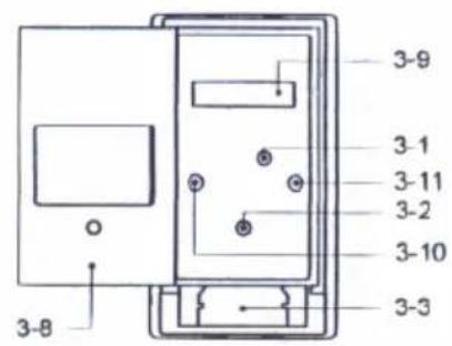
natural_image
Simple line drawing of a rectangular object with a side panel and a label '3-4' (no text or symbols on the object itself)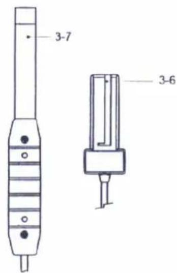
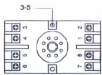
5 and 6 Supply voltage
7 and 8 Current output
1 to 4 Not used
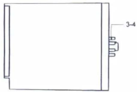
3.1 Calibration potentiometer
3.2 Power light
3.3 Sensor connection (female)
3.4 Connection to mounting plate
3.5 Fixing holes for wall mounting
3.6 Sensor connection (male)
3.7 Sensor
3.8 Transmitter cover
3.9 Setting the measured value ranges
3.10 Light (measured value too low)
3.11 Light (measured value too high)
5 Display description
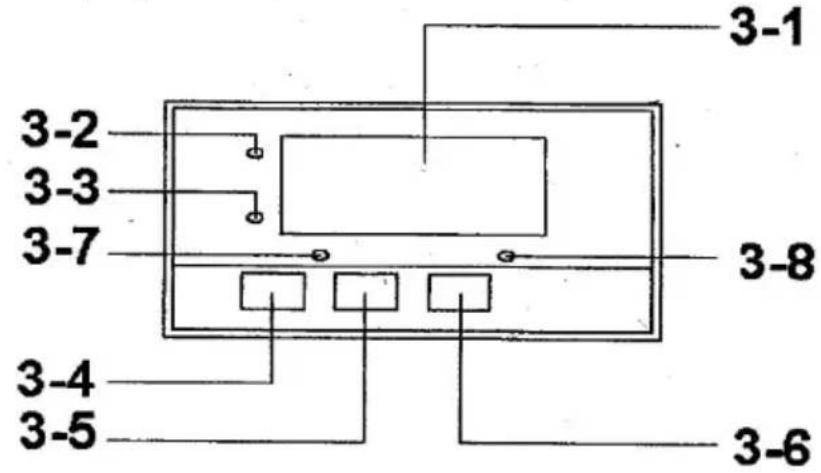
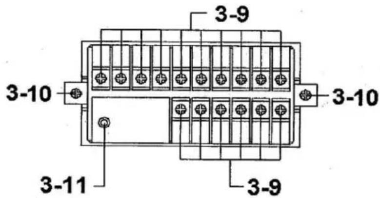
3.1 Display
3.2 Measured value display (indicator)
3.3 Value set display (indicator)
3.4 SET key
3.5 Decrease key
3.6 Increase key
3.7 Control display
3.8 Alarm display
3.9 Terminal strip
3.10 Mounting bracket
3.11 RS232 interface
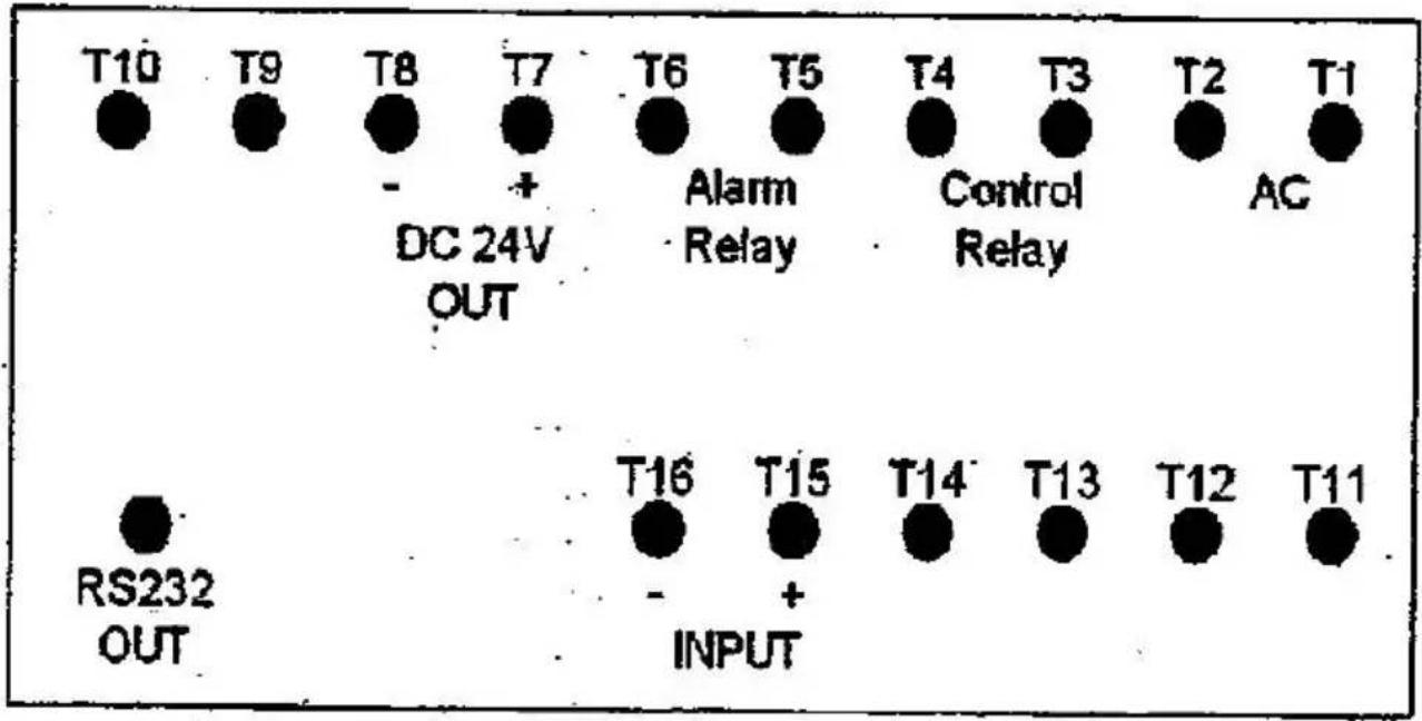
T1 - T2 Power supply
T3 - T4 Control relay
T5 - T6 Alarm relay
T7 - T8 Power supply 24 VDC
T9 - T14 Not connected
T15 - T16 4 ... 20 mA interface
6 Initial commissioning
6.1 Connecting the transmitter
First mount the connection terminal to a designated DIN rail or screw it to a designated surface. First connect the mains voltage. To do this, use connection 5 and 6 on the connection terminal. Ensure that the connection cable is initially voltage-free. Then connect the transmitter to the connection terminal. Finally, connect the sensor to the transmitter.
Note: For the 24 V version of the transmitter (PCE-SLT-TRM-24V), ensure that the supply ground is galvanically isolated from the signal ground.
6.2 Connecting the display
First mount the display using the mounting bracket.
For the power supply, connect the mains cable to the T1 and T2 connections on the display connection terminal. Ensure that the mains supply cable is initially voltage-free.
Now connect the transmitter to the display. To do this, connect pin 7 to T15 (positive) and pin 8 to T16 (negative).
7 Set measurement ranges
First open the transmitter cover. Then remove the internal rubber seal.
The switches for setting the measurement range are now accessible. Use the table on the inside of the transmitter cover to set the measurement range. Then cover the switches again with the rubber seal and close the transmitter cover.
8 Calibration
Open the transmitter cover. Turn the potentiometer labelled "SPAN" to adjust the measured value. To make changes to the potentiometer, use a small slotted screwdriver.
9 Alarm setting (control)
The display has two separate alarm relays. A distinction is made between control and alarm. The difference is that when the alarm switches, the display also flashes, which is not the case with the control.
To programme the limit values of the two functions, proceed as follows:
First press the "SET" key briefly. "CtLo" appears on the display to set the lower control value. You can now set this value directly using the arrow keys. Press the "SET" key to confirm this value and return directly to the menu.
To set other parameters, press the "SET" key continuously until you have reached your parameter. The menu is organised as follows.
CtLo → lower control value CtHi → upper control value ALLo → lower alarm value ALHi → upper alarm value
Once you have set all the parameters, press the "SET" key again to exit the menu.
10 Advanced menu
To access the extended menu, press the "SET" key for two seconds.
This menu is organised as follows:
dPSt Decimal point shift
4-A4 mA parameter
20-A20 mA parameter
FiLt Filter function
CtHY Hysteresis for the control function
ALHY Hysteresis for the alarm function
oFSt Offset
GAIN Gain setting
Unit Set RS232 unit
10.1 Decimal point shift
To move the decimal point, first press the "SET" key for two seconds. "dPSt" appears on the display. Now press the arrow keys to access this configuration mode and to move the decimal point. Press the "SET" key to save the setting.
10.2 4 mA Parameter
To change the parameterisation for 4 mA, first press the "SET" key for two seconds. "dPSt" appears on the display. Press the "SET" key again. "4-A" now appears on the display. Now press the arrow keys to access this configuration mode and to change the parameterisation for 4 mA. Press the "SET" key to save the setting.
10.3 20 mA parameter
To change the parameterisation for 20 mA, first press the "SET" key for two seconds. "dPSt" appears on the display. Now press the "SET" key twice. The display now shows "20-A". Now press the arrow keys to access this configuration mode and to change the parameterisation for 20 mA. Press the "SET" key to save the setting.
10.4 Filter function
To change the parameterisation for the filter function, first press the "SET" key for two seconds. "dPSt" appears on the display. Now press the "SET" key three times. "FiLt" now appears on the display. Now press the arrow keys to access this configuration mode and to change the parameterisation for the filter function. The higher the value, the more filtering takes place. Press the "SET" key to save the setting.
10.5 Hysteresis for the control message
To change the parameterisation of the hysteresis for the control message, first press the "SET" key for two seconds. "dPSt" appears on the display. Now press the "SET" key four times. "CtHY" now appears on the display. Now press the arrow keys to access this configuration mode and to change the parameterisation for the hysteresis. Press the "SET" key to save the setting.
10.6 Hysteresis for the alarm function
To change the parameterisation of the hysteresis for the alarm function, first press the "SET" key for two seconds. "dPSt" appears on the display. Now press the "SET" key five times. "ALHY" now appears on the display. Now press the arrow keys to access this configuration mode and to change the parameterisation for the hysteresis. Press the "SET" key to save the setting.
10.7 Offset
To change the parameterisation for the offset, first press the "SET" key for two seconds. dPSt" appears on the display. Now press the "SET" button six times. The display now shows "oFSt". Now press the arrow keys to access this configuration mode and to change the parameterisation for the offset. Press the "SET" key to save the setting.
10.8 Gain setting
To change the parameterisation for the gain, first press the "SET" key for two seconds. "dPSt" appears on the display. Now press the "SET" key seven times. "GAIN" now appears on the display. Now press the arrow keys to access this configuration mode and to change the parameterisation for the gain. Press the "SET" key to save the setting.
10.9 Set RS232 unit
To change the unit for the RS232 interface, first press the "SET" key for two seconds. "dPSt" appears on the display. Now press the "SET" key eight times. The display will now show "Unit". Now press the arrow keys to access this configuration mode and to change the parameterisation for the unit. The correct value can be found in the following table.
| 00 = No unit | 33 = KHz | 66 = mF |
| 01 = C | 34 = DCV | 67 = MHz |
| 02 = F | 35 = DCμA | 68 = uH |
| 03 = % | 36 = DCA | 69 = dBm |
| 04 = %RH | 37 = DCmA | 70 = Red |
| 05 = pH | 38 = ohm | 71 = Gren |
| 06 = %O2 | 39 = Kohm | 72 = Blue |
| 07 = mg/L | 40 = Mohm | 73 = Stau |
| 08 = m/s | 41 = mH | 74 = mSEC |
| 09 = knot | 42 = H | 75 = uSEC |
| 10 = km/h | 43 = nF | 76 = SEC |
| 11 = ft/m | 44 = μF | 77 = Kgc2 |
| 12 = ml/h | 45 = hFe | 78 = mmHg |
| 13 = uS | 46 = DIO | 79 = mH2O |
| 14 = mS | 47 = WATT | 80 = inHg |
| 15 = Lux | 48 = KWATT | 81 = Kgcm |
| 16 = Ftcd | 49 = ACmV | 82 = LBin |
| 17 = dB | 50 = ACV | 83 = N-cm |
| 18 = mV | 51 = ACμA | 84 = CMM |
| 19 = PPM | 52 = ACA | 85 = CFM |
| 20 = mg | 53 = ACmA | 86 = mbar |
| 21 = Tesl | 54 = COSΘ | 87 = Pa |
| 22 = bar | 55 = Kg | 88 = kPa |
| 23 = PSI | 56 = Lb | 89 = uHg |
| 24 = cmHg | 57 = gram | 90 = Torr |
| 25 = iH20 | 58 = oz | 91 = hPa |
| 26 = ATP | 59 = NewT | 92 = m/s2 |
| 27 = RPM | 60 = m/m | 93 = mm/s |
| 28 = in/m | 61 = Hour | 94 = mm |
| 29 = cm/m | 62 = Min | 95 = cm/s |
| 30 = COUT | 63 = VA | 96 = inch |
| 31 = Hz | 64 = KVA | 97 = FtS2 |
| 32 = DEG | 65 = KWHr | 98 = in/s |
Press the "SET" key to save the setting.
11 RS232
The PCE-SLT has an RS232 interface that can be connected via a 3.5 mm jack. The jack plug must be constructed as follows:
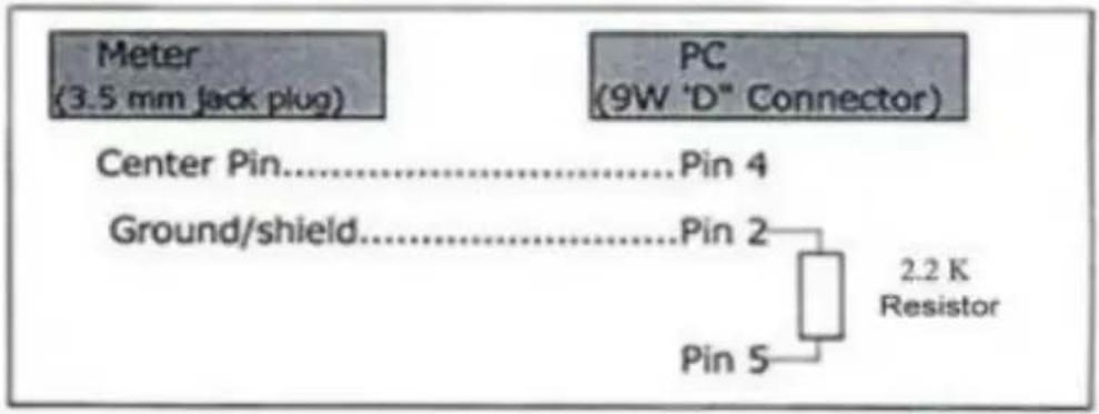
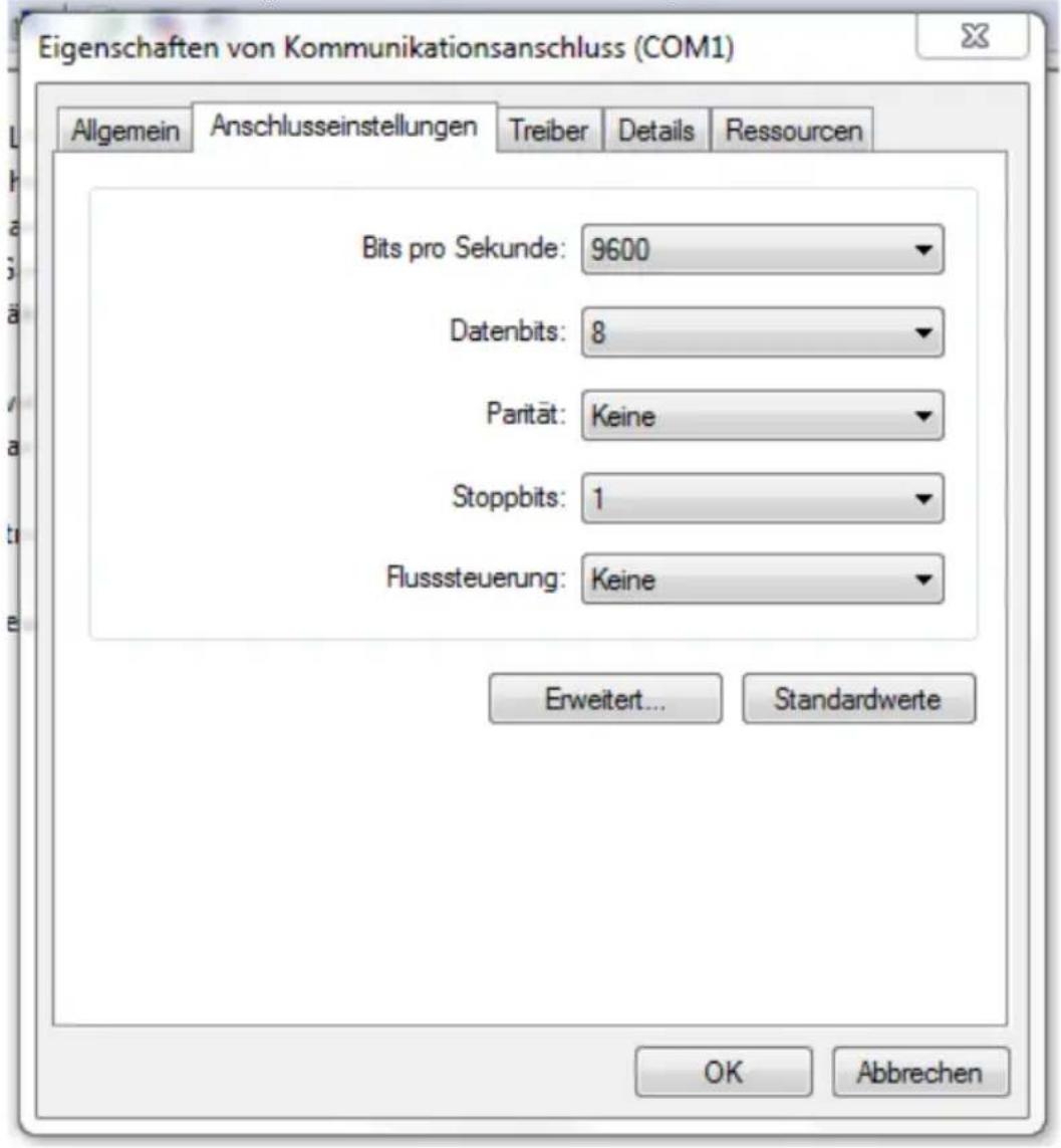
11.1 RS232 settings
To receive the data correctly, set the COM connection on your PC as follows:
The display transmits a 16-digit protocol. This is structured as follows:
| D15 | Start word |
| D14 | 4 |
| D13 | Value too high = 1Value too low = 2 |
| D12 and D11 | Unit, see 10.9 |
| D10 | Positive polarity = 0Negative polarity = 1 |
| D9 | The specified value indicates the position of the decimal point from left to right. Values from 0 ... 3 are possible. |
| D8 ... D1 | The specified values show the measured value from D8 to D1. If the measured value is 1234, for example, the following is sent from D8 to D1:00001234 |
| D0 | End word |
12 Reset system
To reset the system, proceed as follows.
Press and hold the "SET" and the "Decrease" key for five seconds. "rSt" flashes on the display. The system has now been reset. After this, the device returns to measuring mode. After the reset, the device may need to be re-parameterised.
13 Contact
If you have any questions, suggestions or technical problems, please do not hesitate to contact us. You will find the relevant contact information at the end of this user manual.
14 Disposal
For the disposal of batteries in the EU, the 2006/66/EC directive of the European Parliament applies. Due to the contained pollutants, batteries must not be disposed of as household waste. They must be given to collection points designed for that purpose.
In order to comply with the EU directive 2012/19/EU we take our devices back. We either re-use them or give them to a recycling company which disposes of the devices in line with law.
For countries outside the EU, batteries and devices should be disposed of in accordance with your local waste regulations.
If you have any questions, please contact PCE Instruments.




PCE Instruments contact information
Germany France Spain
PCE Deutschland GmbH PCE Instruments France EURL PCE Ibérica S.L.
Im Langel 26 23, rue de Strasbourg Calle Mula, 8
D-59872 Meschede 67250 Soultz-Sous-Forets 02500 Tobarra (Albacete)
Chester Rd, Old Trafford
Manchester M32 0RS
United Kingdom
Tel: +44 (0) 161 464902 0
Fax: +44 (0) 161 464902 9
info@pce-instruments.co.uk
www.pce-instruments.com/english
Italy
PCE Italia s.r.l.
Via Pesciatina 878 / B-Interno 6
55010 Loc. Gragnano Pehlivan Sok. No.6/C
Capannori (Lucca)
Italia
www.pce-instruments.com/turkish
The Netherlands
PCE Brookhuis B.V.
Institutenweg 15
7521 PH Enschede
Nederland
Telefoon: +31 (0)53 737 01 92
info@pcebenelux.nl
www.pce-instruments.com/dutch Fax:+1 (561) 320-9176
info@pce-americas.com
www.pce-instruments.com/us
United States of America
PCE Americas Inc.
1201 Jupiter Park Drive, Suite 8
Jupiter / Palm Beach
33458 FL
USA
Tel: +1 (561) 320-9162
Denmark
PCE Instruments Denmark ApS
Birk Centerpark 40
7400 Herning
Denmark
- User Manual
- Contents
- Safety notes
- Description transmitter
- Initial commissioning
- Connecting the transmitter
- Connecting the display
- Set measurement ranges
- Calibration
- Alarm setting (control)
- Advanced menu
- Decimal point shift
- 4 mA Parameter
- 20 mA parameter
- Filter function
- Hysteresis for the control message
- Hysteresis for the alarm function
- Offset
- Gain setting
- Set RS232 unit
- RS232
- RS232 settings
- Reset system
- Contact
- Disposal
- PCE Instruments contact information
- Germany France Spain
- Italy
- The Netherlands
- United States of America
- Denmark
Brand : PCE Instruments
Model : SLT
Category : Sound Level Meter