
SRK-GM14HX - Replacement Radio Kit PAC - Free user manual and instructions
Find the device manual for free SRK-GM14HX PAC in PDF.


| Product Type | Radio Replacement Kit |
| Brand | PAC |
| Model | SRK-GM14HX |
| Compatible Vehicles | Select GM models (1998-2008) |
| Kit Includes | Dash kit, wiring harness, antenna adapter, mounting brackets, screws |
| Dimensions (Dash Kit) | 7 x 4 x 1.5 inches (approx.) |
| Weight | 1.2 lbs (approx.) |
| Power Requirements | 12V DC, negative ground |
| Connector Type | GM Class II data bus compatible |
| Antenna Adapter | Standard GM antenna to aftermarket radio |
| Installation Difficulty | Moderate – requires basic wiring knowledge |
| Main Features | Retains chimes and RAP, supports steering wheel controls (with adapter) |
| Maintenance | Wipe with dry cloth; do not use liquids |
| Safety | Disconnect battery before installation; avoid short circuits |
| Spare Parts / Repairability | Non-repairable – replace entire kit if damaged |
| General Information | Designed for seamless integration with factory systems |
Frequently Asked Questions - SRK-GM14HX PAC
User questions about SRK-GM14HX PAC
0 question about this device. Answer the ones you know or ask your own.
Ask a new question about this device
Download the instructions for your Replacement Radio Kit in PDF format for free! Find your manual SRK-GM14HX - PAC and take your electronic device back in hand. On this page are published all the documents necessary for the use of your device. SRK-GM14HX by PAC.
USER MANUAL SRK-GM14HX PAC
Introduction and Features
The SRK-GM14HX is a complete radio replacement kit for the installation of the Stinger HEIGH10 (UN1810) modular radio in Chevrolet Silverado and GMC Sierra trucks. All modules, cables and adapters are included to retain important features of the factory system, including: OnStar, front and rear park assist, warning chimes, factory reverse camera, steering wheel-mounted radio controls and AM/FM reception. Plug & Play wiring harnesses allow for quick and easy installation without the need to cut or splice any wiring. The display mounting panel allows flush mounting the 10 inch display without modifying/cutting any part of the vehicle's sub-dash.
Important Notes
We recommend reading this manual thoroughly to familiarize yourself with the entire process prior to beginning the installation.
- Does not retain the following factory features:
• Factory satellite radio
- Valet Mode
- Rear seat entertainment system (RSE)
- Teen Driver Features
• Time of Day in Cluster
- OnStar Text
- Factory USB Ports
• Wi-Fi
- If installing aftermarket amplifiers, the included RPA-SPK can be used to retain OnStar/chimes.
- Chime volume can be adjusted in the HEIGH10's settings
- The Voice button can be set to activate the factory OnStar function when pressed for longer than 1.5 seconds or given the ability to control the aftermarket radio. This option can be found in the Installer Settings on the HEIGH10. By default, this feature is set to control the aftermarket radio, but OnStar can still be accessed by using the mirror controls.
- This guide is applicable to HEIGH10 (UN1810) radios. For ix210 (HORIZON10/HEIGH10+) radios, see the ix210 Installation Guide
Recommended Tools
Plastic Panel Tool
Ratchet
Pick Tool
7mm Socket
Torx T15 Screwdriver
Wire Feeder
10mm Socket
Small Flat-blade Screwdriver
Power Screwdriver
Included Components
- Display Mounting Panel
- Dual USB Extension (SSUSB3)
- AM / FM Antenna Adapter (BAA22)
- Main Harness Adapter (SR-SRK-ADAPT-UN1810)
- Main Harness (SRK-GM14HX-HAR)
- Vehicle Harness Adapter (GM52-ADAPT)
- Radio Replacement Interface (GM6A-SRK)
- Steering Wheel Control Harness (GM5LIN-SW-HAR)
- Factory Rear Camera Adapter (CAM-GM51-HAR)
- IOB Display Harness (GM5CAM-DIS-HAR)
- MOST Loops (MOST Loop 1 / MOST Loop 2)
- External Chime Speaker (RPA-SPK)
- Differential Video Adapter (RPA-VA1)
- Satellite Antenna Adapter (SAT-01)
- Side Mounting Brackets (L & R)
- PAC-Link Cable (10P-2-10P-6)
- PAC-Link Module (PL1)
NOTE: Along with the SRK-GM14HX components, additional hardware and wire harnesses from the HEIGH10 (UN1810) kit will also be used in the installation.


flowchart
graph TD
    A["GM52-ADAPT"] --> B["SRK-GM14HX-HAR"]
    B --> C["CAM GM51 INPUT"]
    C --> D["SWC INPUT"]
    D --> E["CAM-GM51-HAR"]
    E --> F["GM5LIN-SW-HAR"]
    G["RPA-VA1"] --> H["RadioPRO ADVANCED"]
    H --> I["GM6A-SRK"]
    I --> J["GPS"]
    K["SPIN 10PIN USB1"] --> L["STINGER"]
    M["USB2 GRMY BLACK ANT"] --> N["UN1810"]
    O["PGS"] --> P["Ground"]
    Q["AUX Audio"] --> R["PAC Link (PL1)"]
    S["REVERSE CAM"] --> T["REVERSE CAM IN"]
    U["DISP PIN RADIO"] --> V["DISP PIN"]
    W["STICKER"] --> X["STICKER"]
    Y["PPN 16 Pin RADIO"] --> Z["PPN 16 Pin"]
    AA["PSI 16 Pin"] --> AB["PSI 16 Pin"]
    AC["SSUSB3"] --> AD["SSUSB3"]
    AE["PPN 10 Pin"] --> AF["PPN 10 Pin"]
    AG["USB2 GRMY BLACK ANT"] --> AH["USB2 GRMY BLACK ANT"]
    AI["PPN 16 Pin"] --> AJ["PPN 16 Pin"]
    AK["STICKER"] --> AL["STICKER"]
    AM["PPN 10 Pin"] --> AN["PPN 10 Pin"]
    AO["SSUSB3"] --> AP["SSUSB3"]
    AQ["PPN 16 Pin"] --> AR["PPN 16 Pin"]
    AS["STICKER"] --> AT["STICKER"]
    AU["PPN 10 Pin"] --> AV["PPN 10 Pin"]
    AW["SSUSB3"] --> AX["SSUSB3"]
    AY["SAT-01"] --> AZ["SAT-01"]
    BA["PAX22"] --> BB["PAX22"]
    BC["Connects to SXV300 Satellite Radio Tuner (sold separately)"] --> BD["SAT-01"]
Stinger HEIGH10
SRK-GM14HX
Radio Replacement Kit for select
2014-2019Silverado/SierraTrucks
Factory Radio Code
Before starting, determine the vehicle's factory audio system by referencing the Service Parts Identification sticker inside the upper glove box.
One of these RPO codes will be listed:
IO3, IO4, IO5, IO6 or IOB
The installations are very similar for each type of factory audio system, but there are differences referenced throughout this guide.
Note: The installation shown in this guide is IO5 with factory rear camera and steering wheel controls.

This installation manual will cover the necessary order of procedures to complete the installation efficiently and to avoid redoing any steps. The order will be as follows; Disassembly, In-Vehicle Harness Connections and Preparation, Interface and Main Harness Connections, Display Mounting Panel Preparation, Radio Module Preparation and Radio Unit Installation.
The installation steps shown are all required for full functionality of the radio. If adding additional components; cameras, amplifiers, satellite radio, etc., additional steps and harnesses will be needed.
Section 1: Disassembly
Part One: Center Dash Disassembly

natural_image
Interior view of a car dashboard with illuminated status LEDs and control panels (no visible text or symbols)Step 1
Remove the radio display/climate control trim panel using a plastic trim tool to release the retaining clips. Unplug any wire harnesses from the back of the trim panel, if equipped.
natural_image
Interior view of a car dashboard with air filters and a central touchscreen display (no visible text or symbols)Step 2
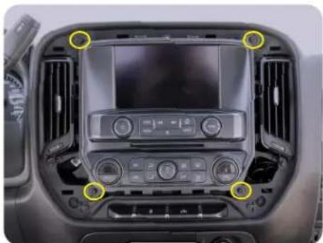
Remove the four 7mm screws securing the radio display/climate control panel. Pull outward to release the retaining clips. Remove all connectors from the back of the panel.
natural_image
Interior view of a vehicle's rear compartment showing internal components and wiring (no visible text or symbols)Step 3
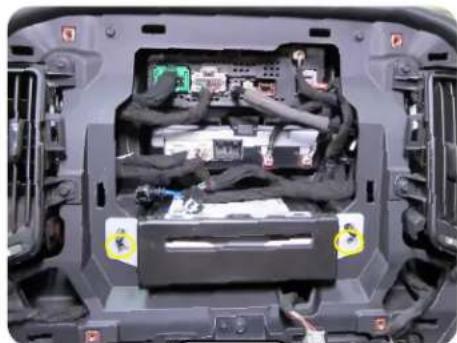
If equipped, remove the two 7mm screws from the CD/DVD mechanism, remove and unplug. Connect one of the included MOST Loops to this connector and tuck into the dash.
Stinger HEIGH10
SRK-GM14HX
Radio Replacement Kit for select
2014-2019Silverado/SierraTrucks
Section 1: Disassembly (Continued)
Part One: Center Dash Disassembly (Continued)

natural_image
Interior view of a car's back panel showing internal components and a highlighted component (no visible text or symbols)Step 4
Unplug all connectors and cables from the upper radio module shown.
natural_image
Close-up of a mechanical component with green and gray connectors, no visible text or symbolsStep 5
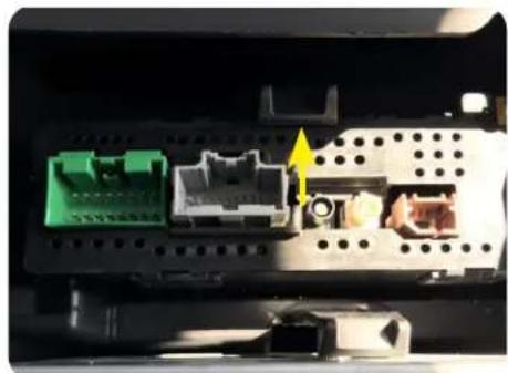
Remove the upper radio module by pushing upward on the locking clip and pulling outward on the module.
Part Two: Lower Storage Compartment Removal
natural_image
Interior view of a car dashboard showing the front and side panels with yellow arrows pointing to specific areas (no text or symbols visible)Step 1
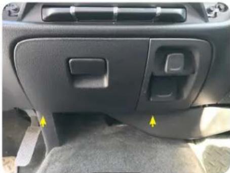
Remove the two Torx T15 screws from the bottom edge of the storage compartment.
natural_image
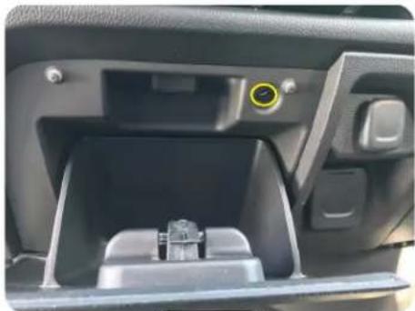
Interior view of a car showing the intake compartment with a yellow circular button and a small mechanical component inside (no text or symbols visible)Step 2 \$step 3
Remove the upper Torx T15 screw inside the storage compartment.
natural_image
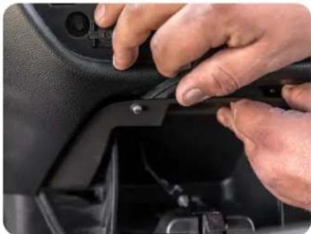
Close-up of hands installing or adjusting a black plastic clip on a car intake manifold (no visible text or symbols)Using a panel tool or similar, release the top retaining clips and remove the storage assembly.
Stinger HEIGH10
SRK-GM14HX
Radio Replacement Kit for select
2014-2019Silverado/SierraTrucks
Section 1: Disassembly (Continued)
Part Three: Glove Box Removal (Optional)
If the vehicle is equipped with IO4, IO5 or IO6 radio AND a factory rear camera, follow the steps below to remove the glove box. For IO3 and IOB vehicles, or no factory rear camera, proceed to Part Four.

natural_image
Close-up of hands installing or adjusting a black car door panel with a tool, no visible text or symbolsStep 1
Remove the two Torx T15 screws from the bottom edge of the lower glove box.
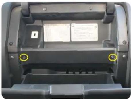
natural_image
Interior view of a car backrest with two yellow circular markers highlighting the front and side panels (no text or symbols visible)Step 2 \$step 3
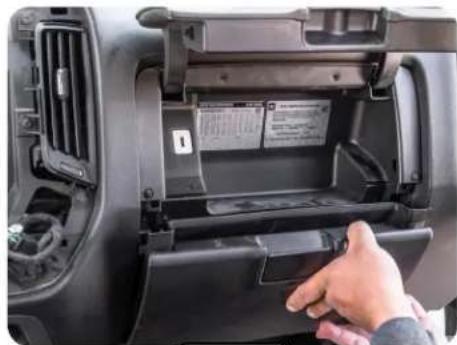
Open the upper and lower glove box doors and remove the two Torx T15 screws securing the lower glove box.
natural_image
Interior view of a car showing a hand inserting a battery into the engine compartment (no visible text or symbols)Pull outward on the lower glove box to release the retaining clips and remove the lower glove box.

Step 4
Remove the two Torx T15 screws and pull to remove the upper glove box. Unplug the factory USB port from the backside.
natural_image
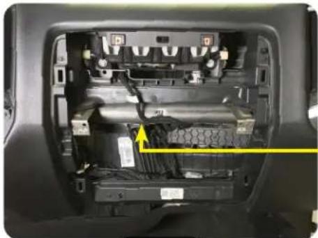
Interior view of a car showing internal components and wiring (no visible text or symbols)Behind the metal bar running across the inner dash, locate the HMI Module; black module with multiple colored plugs facing down.

natural_image
Close-up of a car engine bay with visible wiring and components, no text or symbols presentStep 6Step 5
Unplug the gray 12 pin camera harness from the HMI module.
Stinger HEIGH10
SRK-GM14HX
Radio Replacement Kit for select 2014-2019 Silverado/Sierra Trucks
Section 1: Disassembly (Continued)
Part Four: A Pillar Removal

natural_image
Interior view of a car showing the dashboard and side mirror with yellow arrows pointing to the handle (no text or symbols visible)Step 1 Step 2 Step 3
Remove the inserts covering the bolts on the passenger A pillar handle with a plastic panel removal tool.

natural_image
Interior view of a car showing the front and rearview mirror with two yellow circular markers highlighting the center (no text or symbols visible)Remove the two 10mm bolts.

natural_image
Interior view of a car showing the hood and side panel, with no visible text or symbols.Pull the trim panel to release the retaining clips and remove.
Part Five: Lower Steering Column Cover Removal (Optional)
If the vehicle is equipped with IO3, IO4, IO5 or IO6 radio AND steering wheel controls, follow the steps below to remove the lower steering column cover. For IOB vehicles or no steering wheel controls, proceed to Section Two on next page.

natural_image
Close-up of a car's front bumper with yellow arrows pointing to specific parts (no text or symbols visible)Step 1
Remove the two Torx T15 screws from the bottom edge of knee panel below the steering column. Pull outward to remove the panel and lay carefully on the floor board.
natural_image
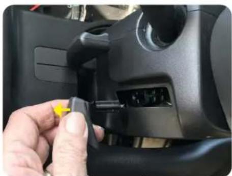
Close-up of a hand inserting a yellow cable into a black car interior (no visible text or symbols)Remove the plastic handle from the steering wheel tilt lever by pulling outward, towards the driver's door on the handle. A trim tool may also be used if unable to remove by hand.

natural_image
Close-up of a car gear shift lever with a hand adjusting the component (no visible text or symbols)Step 3Step 2
Pull downward on the lower cover on both sides to release the locking tabs and remove the lower cover.
Section 2: In-Vehicle Harness Connections and Preparation
Part One: Dual USB Extension (SSUSB3)
Firmware Updates, Apple CarPlay and Android Auto all require access to a USB port. The SSUSB3 is designed to extend the USB ports on the back of the HEIGH10 to where they are accessible once the radio is installed.
For this installation, the factory 12V power outlet will be replaced with the SSUSB3. You may chose to follow these steps, or mount the USB port somewhere else in the vehicle. Please note, the factory USB ports will no longer function after the factory radio is removed.

natural_image
Close-up of a car engine component with a yellow arrow pointing to a component (no visible text or symbols)Step 1
From the backside of the lower storage compartment, remove the metal insert from the power outlet by releasing the two retaining clips with a small pick and pushing out the front side.
natural_image
Close-up of a car's engine compartment showing a yellow warning symbol on the internal component (no text or symbols visible)Step 2
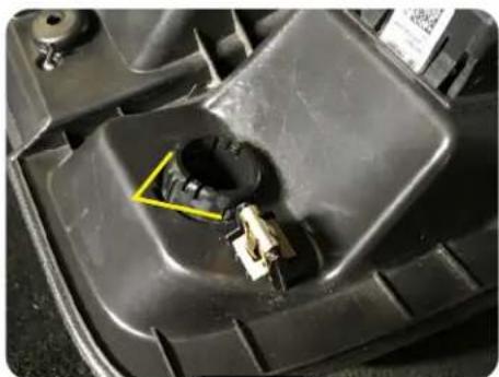
Remove the plastic sleeve by depressing the two tabs and pushing out the front.

natural_image
Close-up of a mechanical device with attached cable and connector (no visible text or symbols)Step 3
Install the optional USB cover and feed the USB cables through the front of the panel. Secure with the flanged nut and then lock with the lock nut.

natural_image
Interior view of a vehicle chassis showing exposed wiring and connectors (no visible text or symbols)Step 4
Route the USB cables up and out of the right side opening at the rear of the CD/DVD opening.
natural_image
Close-up of a black USB cable with metallic connector (no text or symbols visible)Step 5
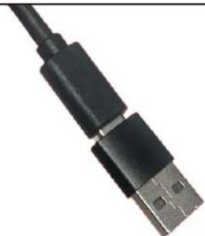
Connect the USB-C to USB-A adapter that was included with the SSUSB3 to the USB-C cable.
Section 2: In-Vehicle Harness Connections and Preparation (Continued)
Part Two: Factory Rear Camera Retention Harness (CAM-GM51-HAR)
If the vehicle is equipped with IO4, IO5 or IO6 radio AND a factory rear camera, follow the steps below to install the factory camera retention harness at the HMI module behind the glove box. For IO3 and IOB vehicles, or no factory rear camera, proceed to Part Four.

natural_image
Interior view of a vehicle battery pack with visible wiring and components (no text or symbols)Step 1
Plug the gray 12 pin camera harness from the HMI module into the CAM-GM51-HAR.

natural_image
Interior view of a car showing internal components and wiring (no visible text or symbols)Step 2 \$step 3
Route the yellow RCA end of the camera cable to the radio opening. Secure plug and cable with zip ties.

natural_image
Interior view of a vehicle showing a cable connector and labeled component (no text or symbols visible)Route the camera RCA out of the left side opening at the rear of the CD/DVD opening.
Part Three: Steering Wheel Control (SWC) Retention Harness (GM5LIN-SW-HAR)
If the vehicle is equipped with IO4, IO5 or IO6 radio AND steering wheel controls, follow the steps below to install the SWC retention harness at the steering column. For IO3 and IOB vehicles, or no steering wheel controls, proceed to Part Four.

natural_image
Close-up of a car's internal components including electrical connectors, wires, and a connector (no visible text or symbols)Step 1 Step 2 Step 3
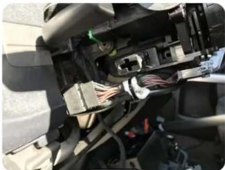
Locate and unplug the black 10 pin connector located on the underside of the steering column.

natural_image
Close-up of car electrical wiring and connectors in a vehicle (no visible text or symbols)Plug the male connector into the female end of the GM5LIN-SW-HAR and plug the GM5LIN-SW-HAR male end into the female connector on the steering column.
natural_image
Close-up of an automotive electrical connector with visible wiring and connectors (no text or symbols)Secure the T-harness to the factory wire harness. Route the 50" single lead from the GM5LIN-SW-HAR to the radio opening, securing with zip ties.
Stinger HEIGH10
SRK-GM14HX
Radio Replacement Kit for select 2014-2019 Silverado/Sierra Trucks
Section 2: In-Vehicle Harness Connections and Preparation (Continued)
Part Three: Steering Wheel Control (SWC) Retention Harness (Continued)

natural_image
Interior view of a vehicle showing wiring and connectors (no visible text or symbols)Step 4
Route the steering wheel control lead into the CD/DVD area through the left side opening in the rear of the cavity.
Part Four: GPS Antenna
The GPS antenna is required for proper operation of Apple CarPlay and Android Auto, in addition to the optional GPS if installed. The GPS antenna is included in the HEIGH10 hardware.

natural_image
Close-up of a car's side profile showing the seatbelt and dashboard (no visible text or symbols)Step 1
Position the GPS Antenna and route the antenna cable down into the glove box area. Replace the A pillar panel and ensure the cable does not interfere or get pinched.

natural_image
Interior view of a car showing internal components and wiring, with no visible text or symbolsStep 2
Continue routing the GPS cable across the inner dash towards the radio opening securing with zip ties.
natural_image
Interior view of a vehicle chassis showing wiring and connectors (no visible text or symbols)Step 3
Route the GPS cable into the CD/DVD area through the right side opening at the rear of the cavity.
Section 3: Interface and Main Harness Connections and Preparation
Part One: RP5-GM51 Radio Interface Connections
Step 1 Step 2
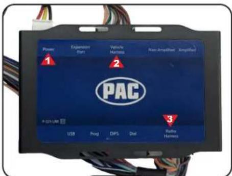
From the Main Harness (SRK-GM14HX-HAR), connect the "Power" (1), "Vehicle Harness" (2) and "Radio Harness" (3) connections to the GM6A-SRK module
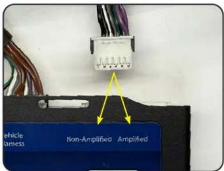
For the speaker output connection, select "Amplified" if your vehicle is equipped with a factory BOSE amplifier or "Non-Amplified" if it is not.
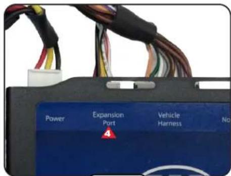
Step 3
Connect the 10 Pin PAC Link Cable (10P-2-10P-6-HAR) to the "Expansion Port."
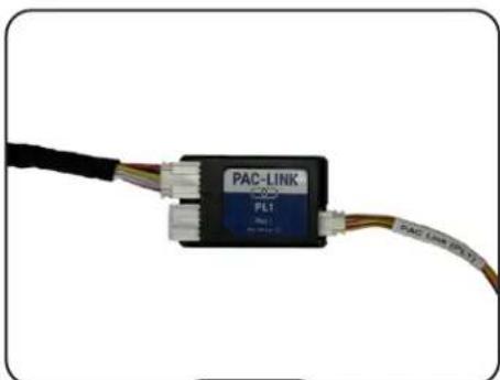
natural_image
Close-up of a PAC-LINK (PLT) cable connector with visible wiring and connectors (no text or symbols on the device itself)Step 4
Connect the other end of the 10 pin PAC Link Cable to the PAC Link Module (PL1). From the 10 Pin Multi Camera Harness (SE-1104) connect the 3 pin connector labeled "PAC Link" to the PAC Link Module.

natural_image
Close-up of connected electronic components with multicolored wires (no visible text or symbols)Step 5
Connect the 2 pin, 8 pin and 14 pin connectors from the Main Harness Adapter (SR-SRK-ADAPT-UN1810) to the Main Harness (SRK-GM14HX-HAR).

natural_image
Pure electrical circuit lines without any symbolsStep 6
From the Main Harness Adapter, connect the pink "Speed Sen" wire to the pink "Speed Sen" wire on the 10 Pin Multi Camera Harness.
Section 3: Interface and Main Harness Connections and Preparation (Continued)
Part Two: Main Harness Connections (SR-GM14H-HAR-A) (Continued)

natural_image
Close-up of a PAC-LINK PLC cable connector with multicolored wires (no visible text or symbols on the device body)Step 7
Zip tie the PAC Link Module to the Main Harness.
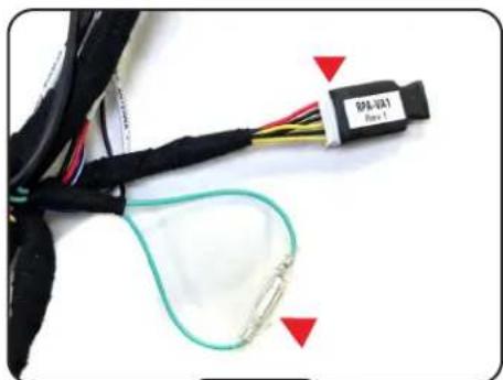
natural_image
Close-up of a black cable with wires and connectors, connected by a green wire (no visible text or symbols)Step 8
Connect the Differential Video Adapter (RPA-VA1) to the 6-pin lead on the Main Harness. Connect the male and female ends of the Light Green leads together.
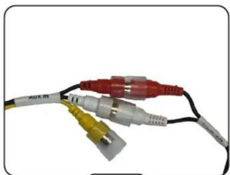
natural_image
Close-up of three colored audio/video connectors with black, white, and red wires (no text or symbols visible)Connect the "AUX Audio" RCAs from the Main Harness to the "AUX IN" RCAs on the HEIGH10's 24 Pin AV / Rear Camera Harness (SE-1103).

Step 10\$step 9
Connect the "REVERSE CAM" RCA from the Main Harness to the "REVERSE CAMERA IN" RCA on the 24 Pin AV / Rear Camera Harness.
Stinger HEIGH10
SRK-GM14HX
Radio Replacement Kit for select
2014-2019 Silverado/Sierra Trucks
Section 4: Display Mounting Panel Preparation
Part One: Transferring the Climate Controls

natural_image
Close-up of a hand installing or adjusting a white plastic component on a black electronic device casing (no visible text or symbols)With the factory radio display / climate control panel face down, apply slight pressure to the front of the controls while releasing the locking tabs around the perimeter.

natural_image
Close-up of a hand holding a plastic battery cover inside a black electronic device casing (no visible text or symbols)Step 2 Step 1 Step 3
Once all the clips are released, remove the climate controls from the factory bezel.

natural_image
Exterior view of a black plastic automotive chassis with internal compartments and mounting points (no text or symbols visible)Align the controls on the back side of the Display Mounting Panel and push to seat and lock all the retaining clips.
Part Two: Mounting the Display

natural_image
Interior view of a car dashboard with control panels and a central touchscreen display (no visible text or symbols)Step 1
Insert the Touch Panel Display into the front of the Display Mounting Panel and carefully turn the panel over while holding the display in place.
natural_image
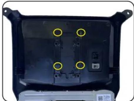
Back view of a black plastic enclosure with four yellow circular annotations pointing to internal components (no text or symbols visible)Step 2
Attach the display to the panel using four M4 x 12 screws.
Stinger HEIGH10
SRK-GM14HX
Radio Replacement Kit for select 2014-2019 Silverado/Sierra Trucks
Section 5: Radio Module Preparation
Part One: Radio Module Side Brackets
natural_image
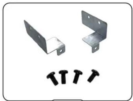
Two metal L-bracket components and four black screw fasteners arranged below (no text or symbols)Locate the two Side Mounting Brackets and four M5x10 screws.

natural_image
Exterior view of a computer drive chassis with visible ports and connectors (no text or symbols)Step 2 Step 3 Step 1
Using two M5x10 screws attach one side bracket as shown above.

natural_image
Exterior view of a mechanical electronic device with cooling fins and a blue indicator light (no visible text or symbols)Using two M5x10 screws attach the other side bracket as shown above.
Section 6: Radio Unit Installation
Part One: Mounting the Radio Module
natural_image
Internal view of an electronic device showing ports, connectors, and wiring (no visible text or symbols)Step 1
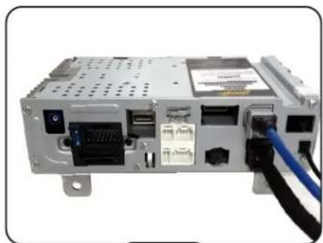
From the HEIGH10 box, connect the LVDS Display Video Cable (SE-1101) and 8 Pin Display Power Harness (SE-1100) to the Radio Module.

natural_image
Interior view of a computer chassis showing internal components and connectors (no visible text or symbols)Step 2
Inside the truck, slide the HEIGH10 Radio Module into the upper compartment until the bracket tabs contact the sub dash. Secure with supplied #8 x 1/2" screws.
Stinger HEIGH10
SRK-GM14HX
Radio Replacement Kit for select 2014-2019 Silverado/Sierra Trucks
Part Two: In-Vehicle Harness and Cabling Connections
Step 1A
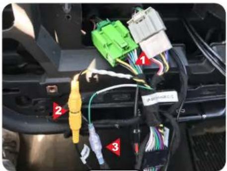
IO3, IO4, IO5, IO6: Connect the Green and Gray Main Harness (SRK-GM14HX-HAR) (1) connectors to the matching plugs in the vehicle.
IO4, IO5, IO6: If equipped, connect the Yellow RCA from the CAM-GM51-HAR to the "CAM-GM51 INPUT" (2) and connect the wire from the GM5LIN-SW-HAR to the "SWC INPUT" (3).

natural_image
Close-up of a person's arm holding an electronic device with cables and connectors, next to a computer interface (no visible text or symbols)(Step 1B)Step 1C
IO5 or IO6: Connect the 8 pin gray connector from the Main Harness to the matching 8 pin gray connector in the vehicle that was removed from the OEM radio.

natural_image
Close-up of a hand holding a white connector with multicolored wires, partially installed in a device (no visible text or symbols)IOB:
Connect the Mustard and Gray GM52-ADAPT connectors to the matching plugs in the vehicle. Connect the other end to the Main Harness.
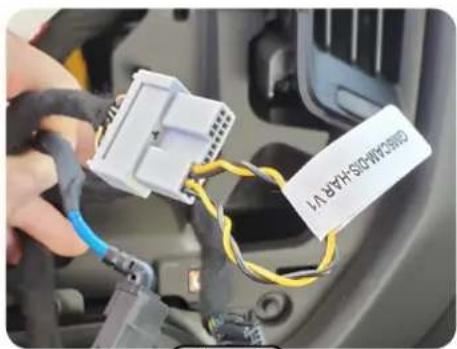
Step 2
2018-19 IOB Only: Plug the 20 pin harness that was removed from the factory display into the GM5CAM-DIS-HAR.
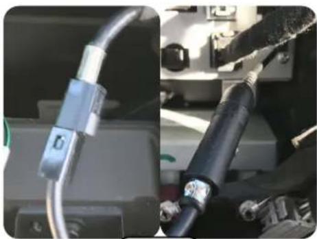
natural_image
Close-up of mechanical components including a metallic cable and a black cylindrical component (no visible text or symbols)Connect the AM/FM Antenna Adapter (BAA22) to the black factory antenna cable.
Plug the other end of the BAA22 into the antenna port on the Radio Module.
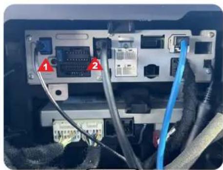
natural_image
Internal wiring diagram showing connections between electronic devices (no text or symbols visible)Step 4Step 3
Connect the GPS Antenna (1) and the two USB cables (2) to the Radio Module. Either USB cable can be connected to either USB input, but the USB on top (closest to the edge of the radio) will handle Apple CarPlay and Android Auto.
Stinger HEIGH10
SRK-GM14HX
Radio Replacement Kit for select
2014-2019Silverado/SierraTrucks
Section 6: Radio Unit Installation (Continued)
Part Two: In-Vehicle Harness and Cabling Connections (Continued)

Step 5 \$step 6
From the SR-SRK-ADAPT-UN1810 harness, connect the "16 PIN RADIO" (3) and "Steering Wheel Control" (4) connectors to the Radio Module.

natural_image
Close-up of a device's cable and connector with a red arrow pointing to a component (no visible text or symbols)Connect the 24 Pin AV / Rear Camera Harness (5) to the Radio Module.

natural_image
Close-up of a computer interface showing cable connections and a labeled component (no readable text or symbols)Step 7
Connect the 10 Pin Multi Camera Harness (6) to the Radio Module.
These are the connections for a typical installation. If adding additional cameras, amplifiers or satellite radio, those connections should be made at this point.

natural_image
Interior view of a car showing wiring connections to a vehicle's rear panel (no readable text or symbols)Step 8
Use the supplied two-sided tape to secure the Radio Replacement Interface in the lower CD/DVD cavity.

natural_image
Close-up of a car electrical connector with two yellow-circled components and a blue cable (no visible text or symbols)Step 9
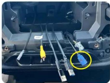
Plug the two display cables (SE-1100/SE-1101) into the back of the Touch Panel Display. Re-connect the factory climate control connector to the climate controls.
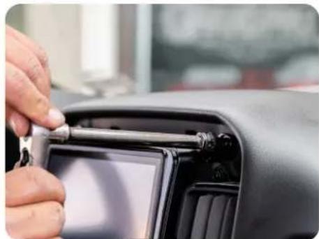
natural_image
Close-up of a hand adjusting a car interior panel with a tool (no visible text or symbols)Step 10
Place the Display Mounting Panel in place and temporarily secure it with two 7mm screws.
Before reassembly, it is recommended to start the vehicle and check the chime volume and all other functionality...
Volume, Balance, Fade Steering Wheel Controls
AM/FM Reception
USB
Android
Auto
Bluetooth
Apple
Carplay
Camera(s)
Product Updates (Firmware)
Firmware Updates (RadioPRO)
The PAC GM6A-SRK interface can be updated with new firmware as it becomes available. Please visit www.PAC-audio.com/firmware for available updates.
Firmware Updates (Stinger Radio and PAC Application APK)
To update the HEIGH10 radio firmware and PAC Application APK firmware, refer to:
https://stingersolutions.com
RadioPRO LED Feedback
LED 1:
Blinks Red - Interface is configuring
Solid Red - Accessory power is on
Flashes Green - SWC button pressed
Blinking Green - SWC remap
Off - Accessory power is off
LED 2:
Solid Green - Interface is running
Blinking Amber - Connected to USB
Off - Interface is sleeping
LED 1 & 2:
Alternating Blinking Amber - Interface is entering sleep
Alternating Blinking Red - Master reset
Technical Support
Email: support@StingerSolutions.com
Phone: 727-592-5991
- Introduction and Features
- Important Notes
- We recommend reading this manual thoroughly to familiarize yourself with the entire process prior to beginning the installation.
- Recommended Tools
- Included Components
- Stinger HEIGH10
- SRK-GM14HX
- Factory Radio Code
- Section 1: Disassembly
- Part One: Center Dash Disassembly
- Section 1: Disassembly (Continued)
- Part Three: Glove Box Removal (Optional)
- Part Five: Lower Steering Column Cover Removal (Optional)
- Section 2: In-Vehicle Harness Connections and Preparation
- Part One: Dual USB Extension (SSUSB3)
- Section 2: In-Vehicle Harness Connections and Preparation (Continued)
- Part Two: Factory Rear Camera Retention Harness (CAM-GM51-HAR)
- Part Three: Steering Wheel Control (SWC) Retention Harness (GM5LIN-SW-HAR)
- Part Four: GPS Antenna
- Section 4: Display Mounting Panel Preparation
- Section 5: Radio Module Preparation
- Section 6: Radio Unit Installation
- Section 6: Radio Unit Installation (Continued)
- Part Two: In-Vehicle Harness and Cabling Connections (Continued)
- Product Updates (Firmware)
- Firmware Updates (RadioPRO)
- Firmware Updates (Stinger Radio and PAC Application APK)
- RadioPRO LED Feedback
- LED 1:
- LED 2:
- LED 1 & 2:
- Technical Support
Brand : PAC
Model : SRK-GM14HX
Category : Replacement Radio Kit