
ZGBBQ3B01-C - Barbecue ZANUSSI - Free user manual and instructions
Find the device manual for free ZGBBQ3B01-C ZANUSSI in PDF.


| Product Type | Barbecue |
| Brand | Zanussi |
| Model | ZGBBQ3B01-C |
| Power Source | Gas (LPG) |
| Number of Burners | 2 |
| Total Power Output | 8 kW |
| Cooking Area | 2500 cm² |
| Material | Stainless Steel |
| Ignition Type | Piezo |
| Built-in Thermometer | Yes |
| Side Shelves | Yes |
| Dimensions (W x D x H) | 120 x 60 x 110 cm |
| Weight | 25 kg |
| Cooking Grid Material | Porcelain enameled cast iron |
| Safety Features | Flame failure device |
| Cleaning | Removable drip tray, easy-clean grates |
| Warranty | 2 years |
Frequently Asked Questions - ZGBBQ3B01-C ZANUSSI
User questions about ZGBBQ3B01-C ZANUSSI
0 question about this device. Answer the ones you know or ask your own.
Ask a new question about this device
Download the instructions for your Barbecue in PDF format for free! Find your manual ZGBBQ3B01-C - ZANUSSI and take your electronic device back in hand. On this page are published all the documents necessary for the use of your device. ZGBBQ3B01-C by ZANUSSI.
USER MANUAL ZGBBQ3B01-C ZANUSSI

Please scan the QR code for step by step video assembly instructions. Alternatively, you can visit: at
www.zanussicomfortandoutdoors.com. From here, please select the product that you are looking to build and view the 'How To' video located at the bottom of the page.
WARNING: PLEASE ENSURE YOU HAVE READ THROUGH THE SAFETY AND OPERATING INSTRUCTIONS BEFORE USE.
PLEASE RETAIN INSTRUCTIONS FOR FUTURE REFERENCE
For Customer Services & Spare Parts please call 0330 1230 597
Or visit us at www.zanussicomfortandoutdoors.com
CONTENTS
| Page(s) | |
| Safety instructions | 3-5 |
| BBQ Feature Diagram & Parts List | 6-8 |
| BBQ Assembly | 9-26 |
| Attaching Gas Cylinder | 27 |
| Disconnecting Gas cylinder | 28 |
| Lighting your BBQ | 29 |
| Food Safety | 30 |
| Tips for use | 31 |
| Storage | 32 |
| Cleaning and care | 33 |
| Troubleshooting | 34-35 |
| Guarantee and customer services | 36 |
| Notes | 37-39 |
SAFETY INSTRUCTIONS
IMPORTANT SAFETY INSTRUCTIONS READ CAREFULLY AND KEEP FOR FUTURE REFERENCE
WARNING:
- The Barbeque must be installed on a secure level base prior to use.
- Read the instructions before using the appliance.
•Always light the barbecue with the lid open.
- Check and clean the grease trays regularly.
- The gas hose should be checked regularly for leaks (especially after long breaks).
- Never use water to extinguish flames.
- Turn off the gas supply at the gas cylinder after use.
- Any modification to the appliance may be dangerous and will void the guarantee.
- Do not store or use gasoline or mentholated fuels or any other flammable vapors and liquids in the vicinity of this appliance. Never light a gas grill with gasoline or similar flammable fluids!
- When the wind speed is above 2m/s don’t use the appliance facing in to the find as this may case the flame to extinguish.
- Never mount the gas cylinder under the appliance or near any parts of the appliance which becomes hot as this could result in serious injury.
- Use protective heat resistant gloves when handling particularly hot components.
- The appliance must be installed with 1m clearance in all directions around the appliance and should not be used underneath any overhead obstruction.
- In the event of a gas leak, turn off the gas supply at the gas cylinder, extinguish any open flames and keep the lid open. If the leak continues contact your local gas dealer immediately.
DO NOT USE AN OPEN FLAME TO CHECK FOR GAS LEAKS
•Always test the gas line for leaks with soapy water. If there are leaks you should see bubbles forming.
•The lid must always be open when lighting the appliance.
- Be prepared if an accident or fire should occur. Know where the first aid kit and fire extinguishers are and how to use them.
- Do not heat any unopened glass or metal container on the grill. Pressure may build up and cause the container to burst, possibly resulting in serious personal injury or damage to the appliance.
- WARNING! This barbecue will become very hot, do not move it during operation.
- Do not use indoors or in enclosed spaces!
- WARNING! Do not use spirit or petrol for lighting or re-lighting! Use only firelighters complying to EN 1860-3!
- WARNING! Keep children and pets away.
WARNING! Do not use the barbecue in a confined and/or habitable space e.g. houses, tents, caravans, motor homes, boats. Danger of carbon monoxide poisoning fatality.
SAFETY CHECKS BEFORE USE
- If you smell gas shut off gas to the appliance, extinguish any open flames, open lid and if the odour continues, keep away from the appliance and immediately call your gas supplier or your fire department. Leaking gas may cause a fire or explosion which can cause serious bodily injury, death, or damage to property.
- Never operate this appliance unattended, always ensure there are at least two people present.
- Check hose before each use of grill for nicks, cracking, abrasions or cuts. If the hose is found to be damaged in any way, do not use the grill.
Technical data
| ZANUSSI 3 BURNER GAS BBQ with Side Burner ZGBBQ3B01-C (SRGG30005-A) UKCA Pin Code: 0063CT7097 | |||||
| Country of Destination | Appliance Category | Gas and Supply Pressure | Main Burner Injector Size ∅ | Side Burner Injector Size ∅ | Total Nominal Heat Inputs (Hs) |
| GB | I3+(28-30/37) | Butane (G30) 28-30mbar | 0.91 mm | 0.90 mm | 14.0kW 1019g/h |
| Propane (G31) 37mbar | 0.91 mm | 0.90 mm | 14.0kW 1001g/h | ||
| CE 0063-22 CE Pin Code: 0063CT7097 | |||||
| Country of Destination | Appliance Category | Gas and Supply Pressure | Main Burner Injector Size ∅ | Side Burner Injector Size ∅ | Total Nominal Heat Inputs (Hs) |
| BE, CH, CY, CZ, ES, FR, GB, GR, IE, IT, LT, LU, LV, PT, SK, SI | I3+(28-30/37) | G30 Butane at 28-30mbar | 0.91 | 0.90 | 14.0kW 1019g/h |
| Propane G31 at 37mbar | 0.91 | 0.90 | 14.0kW 1001g/h | ||
| GB, CY, DK, EE, FR, FI, HU, IT, LT, NL, NO, SE, SI, SK, RO, HR, TR, BG, IS, LU, MT | I3B/P (30) | Butane G30 and Propane G31 at 30mbar | 0.91 | 0.90 | 14.0kW 1019g/h |
| AT, CH, DE, SK | I3B/P (50) | Butane G30 and Propane G31 at 50mbar | 0.78 | 0.79 | 14.0kW 1019g/h |
| Caution:USE OUTDOORS ONLY. If stored indoors, detach and leave cylinder outdoors.Read instructions before using the appliance.The gas cylinder should not be placed inside the BBQ.WARNING : Accessible parts may be very hot. Keep young children away.Minimum clearance from side and back of unit to combustible construction: 100cmMade in P.R. ChinaZANUSSI is a registered trademark used under license from AB Electrolux (publ).Made by Product Care Trading Limited, Wigan, WN2 4AY/ PCT (NI) Ltd, Belfast, BT5 5AD.ZANUSSI support: call 03301230597or visit www.zanussiheatingandcooling.uk | |||||
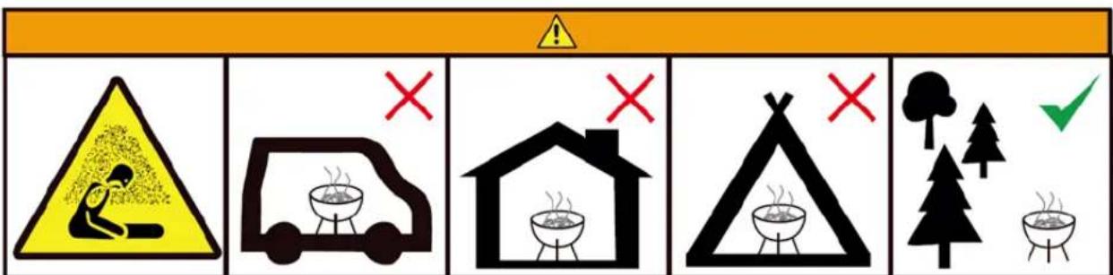
Carbon Monoxide Poisoning Hazard
Do not use in Motor Homes
Do Not Use Indoors
Do Not Use in Tents
Use in open Spaces
FEATURE DIAGRAM

PARTS LIST
| Ref | Description | Visual | Qty |
| 1 | Lid |  | 1 |
| 2 | Flame Tamer |  | 3 |
| 3 | Grease Tray | 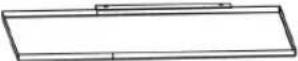 | 1 |
| 4 | Side BurnerPan Support | 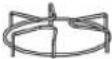 | 1 |
| 5 | Side BurnerShelf |  | 1 |
| 6 | Side Burner |  | 1 |
| 7 | Dial Bezel | [87SW] | 4 |
| 8 | Dial |  | 4 |
| 9 | Right Panel |  | 1 |
| 10 | Ignitor | 1 | |
| 11 | Regulator & Hose |  | 1 |
| 12 | Wheel |  | 2 |
| 13 | Wheel Cap | 2 | |
| 14 | Warming rack |  | 1 |
| Ref | Description | Visual | Qty |
| 15 | Cooking Grid |  | 2 |
| 16 | Hook | [2466] | 3 |
| 17 | Handle & Bezel |  | 1 |
| 18 | Left Side Shelf | 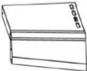 | 1 |
| 19 | Side Burner Valve |  | 1 |
| 20 | Grill Body | 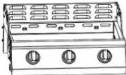 | 1 |
| 21 | Left Panel |  | 1 |
| 22 | Condiment shelf |  | 1 |
| 23 | Lower Front Panel |  | 1 |
| 24 | Rear leg foot | [HVTK] | 1 |
| 25 | Front leg foot | [SGC8] | 1 |
| 26 | Bottom Panel |  | 1 |
| 27 | Main Gas Burner | [802C] | 3 |
| 28 | Flame Channel | [G85S] | 2 |
PARTS LIST
| Ref | Dimensions | Visual | Qty |
| AA | M5 x 12 | 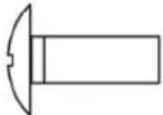 | 20 |
| BB | M4 x 10 | 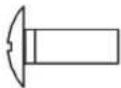 | 2 |
| CC | M10 x 75 | 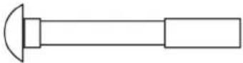 | 2 |
| DD | M10 |  | 2 |
| EE | D10 |  | 2 |
| - | BBQ Cover | ZANUSSI | 1 |
BBQ ASSEMBLY
Assembling the Stand
- Attach the Rear & Front Leg Feet (24 & 25) to the Left Panel (21).

BBQ ASSEMBLY
Assembling the Stand
- Thread the M10 Screws (CC) through the inside of the holes at the bottom of each leg of the Right Panel (9). Then put the Washers D10 (EE), Wheels (12), Nuts M10 (DD) on the M10 Screw end that is sticking out from each leg. With a spanner holding the Nut M10 (DD) and tighten the M10 Screws with a cross headed screwdriver. Then fit the Wheel Caps (13).

BBQ ASSEMBLY
Assembling the Stand
- Attach the Bottom Panel (26) to the Right Panel (9) and Left Panel (21) with 4 M5 Screws (AA).


BBQ ASSEMBLY
Assembling the Stand
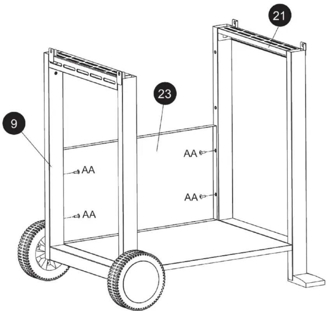
- Attach the Lower Front Panel (23) to the Right Panel (9) and Left Panel (21) with 4 M5 Screws (AA).

BBQ ASSEMBLY
Assembling the Stand
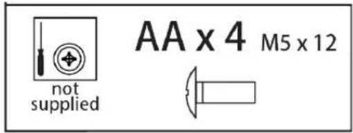
- Attach the Condiment Shelf (22) to the Right Panel (9) and Left Panel (21) with 4 M5 Screws (AA).

BBQ ASSEMBLY
Assembling the Grill
- The Grill Body (20) and the Lid (1) are pre-assembled, attach it to the stand with 4 M5 Screws (AA).


BBQ ASSEMBLY
Assembling the Grill
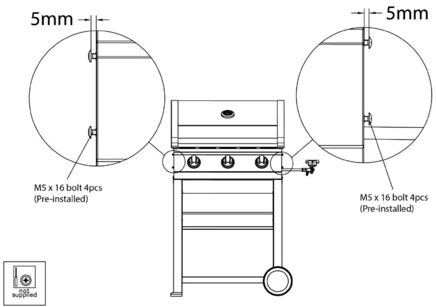
- There are 4 preinstalled M5 x 16 Screws on the sides of the Grill Body (20), ensure there is a gap of 5mm from the screw head and the Grill Body (20).
BBQ ASSEMBLY
Assembling the Grill
- Hook the Left Side Shelf (18) on to the 4 preinstalled screws that were detailed in the previous step. Ensure the Left Side Shelf (18) is correctly fitted before tightening the 4 Screws. Then attach it to the control panel on the Grill Body (20) with 2 M5 Screws (AA).

BBQ ASSEMBLY
Assembling the Grill
- Hook the Side Burner Shelf (5) on to the 4 preinstalled screws that were detailed in the step 2. Ensure the Side Burner Shelf (5) is correctly fitted before tightening the 4 Screws. Then attach it to the control panel on the Grill Body (20) with 2 M5 Screws (AA).
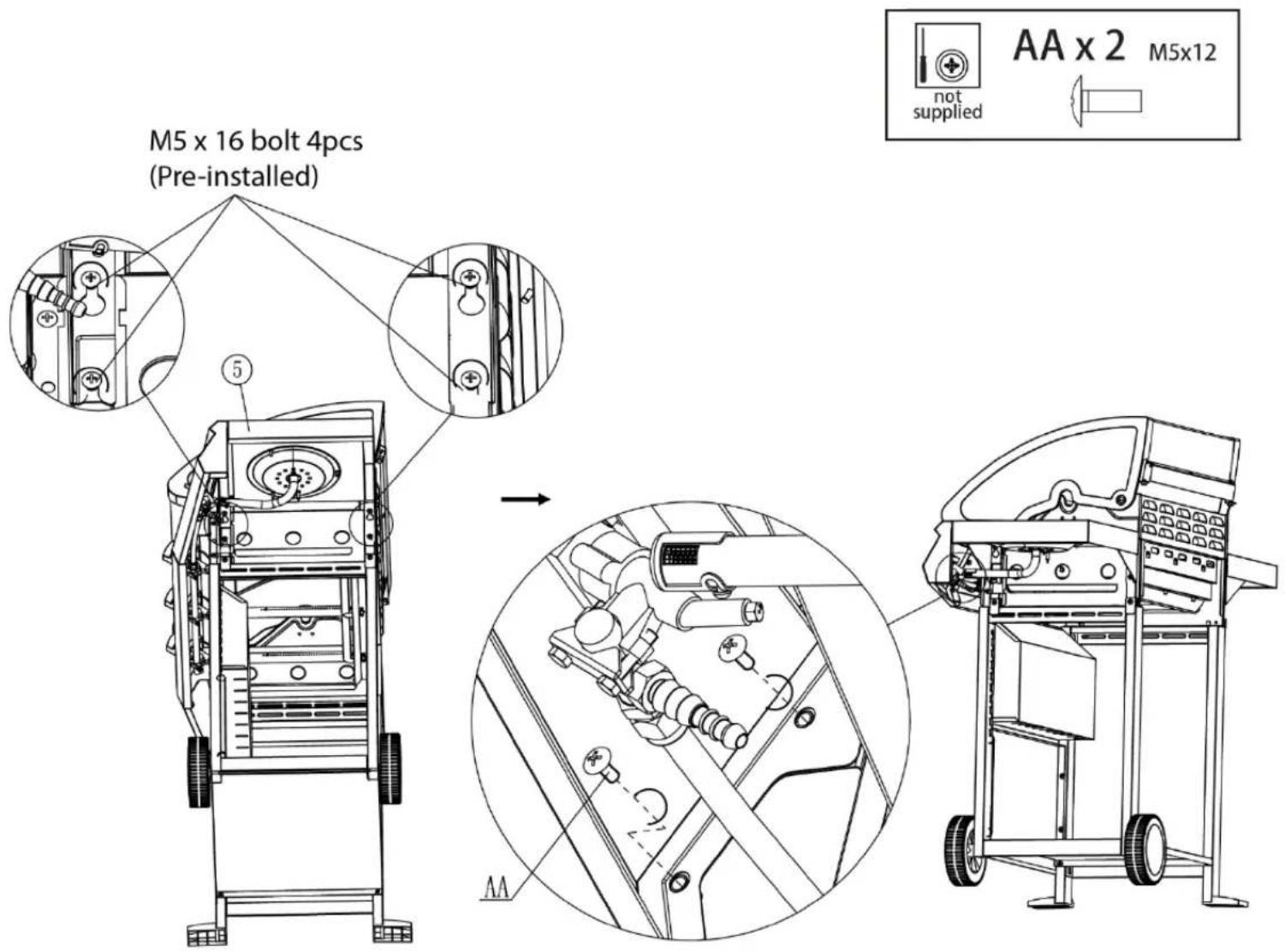
BBQ ASSEMBLY
Assembling the Grill
- Remove the 2 preinstalled screws.

BBQ ASSEMBLY
Assembling the Grill
- Fit the Dial Bezel (7) with 2 M4 Screws (BB) over the Side Burner Valve (19). Then fit the Dial (8) by aligning the marking on the dial and the off position on the control panel before pushing the Dials (8) on to the gas taps.


BBQ ASSEMBLY
Assembling the Grill
- Fit the bottom part of the side burner valve (19) to the gas valve coming from the Side Burner (6), you must ensure it is connected correctly and fully inserted. Connect the Ignitor (10) by pushing it into the underside of the Side Burner (6), you must ensure it is connected correctly and fully inserted. Then refit the screws removed in the previous step.

BBQ ASSEMBLY
Assembling the Grill
- Check the burner cover and spreader on the Side Burner (6) is between 3mm and 5mm from the ignitor and place the Side Burner Pan Support (4) on top of the Side Burner (6).

BBQ ASSEMBLY
Assembling the Grill
- Remove the screws from the ends of the Handle (17) and then slot the Hooks (16) on to the Handle (17). Connect the Handle (17) to the Left Side Shelf (18) and fit it in place with the screws.


BBQ ASSEMBLY
Assembling the Grill
- Slot the Grease Tray (3) into the back of the BBQ.
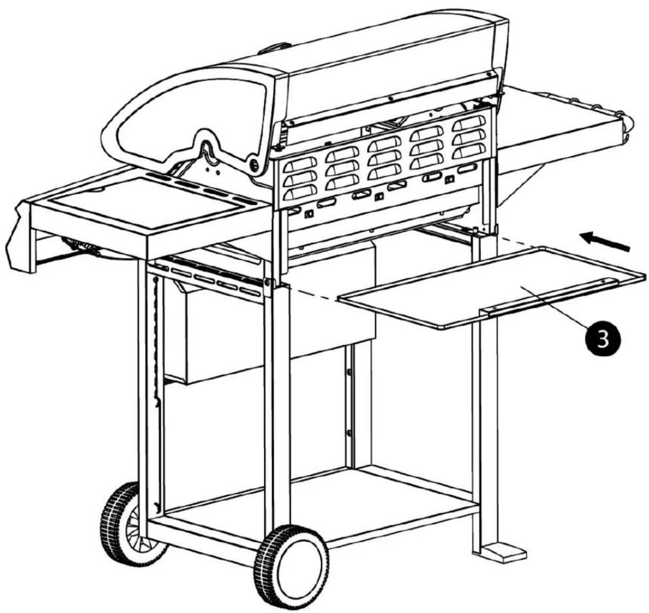
BBQ ASSEMBLY
Assembling the Grill
- Place the Flame Tamers (2) above the Main Burners (27), ensuring they are resting on the side brackets. Then place the Cooking Grids (15) into the BBQ and slot the Warming Rack (14) on to the frame of the gas BBQ so that the rear of the warming rack is over the back plate of the frame.
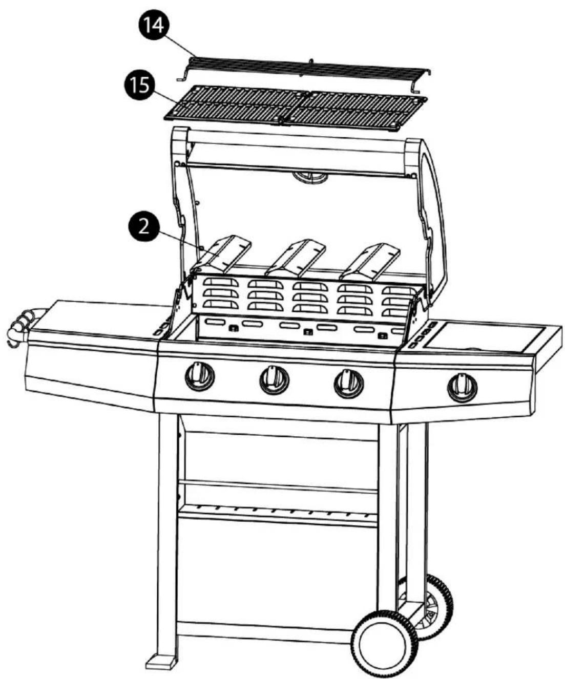
BBQ ASSEMBLY
Assembling the Grill
- Connect the Hose and Regulator (11) to the gas valve on the underside of the control panel
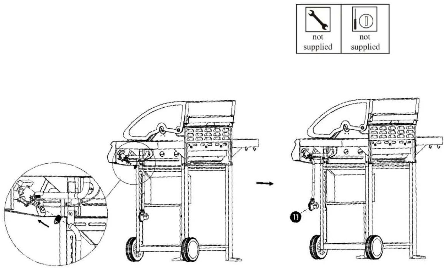
BBQ ASSEMBLY
WARNING:
ATTACHING YOUR GAS CYLINDER
After purchasing your gas cylinder you will then be ready to set it up with your gas grill. When changing the gas cylinder it must not be near any source of ignition.
Position the gas cylinder at the left side (right side as you look at it) of your gas grill, keeping in mind that the bottle must be kept away from heat and in a safe position.
- When ready to use your gas grill place the regulator onto the gas bottle valve and push down firmly until you hear it click in to place.
- Attach the hose to the regulator gas outlet, you will need to push firmly as it is a tight fit.
- Once the hose is connected to regulator it must be secured in place using one of the two jubilee clips supplied.
- Attach the other end of the gas hose to the gas inlet on the appliance, again you will need to push firmly as it is a tight fit.
- Once the hose is connected use the second jubilee clip to secure in place.
- Ensure that the hose is not subjected to twisting which will affect the gas flow when installing your gas grill. Also the hose must not have undue tension and must not touch any part of the gas grill which may be hot.
- Once the gas cylinder is connected to the appliance you can then start the flow of gas by turning the small lever on the regulator from its closed position (horizontal) to its open position (vertical).
Warning: Always test gas line for leaks at connector with soap water around all connections.
DISCONNECTING YOUR GAS CYLINDER
When you have finished using the appliance you must remove the gas cylinder.
In order to do this you turn the small lever on the regulator from its open position (vertical) to its closed position (horizontal).
Once the gas supply has been turned off you then need to remove the regulator from the gas cylinder. To do this you need to push in the button release which is located below the small lever on the regular and lift away from the gas cylinder.
LIGHTING YOUR BBQ
USING THE AUTOMATIC IGNITION
Caution: The lid must be open when lighting the BBQ
Do not stand with your face directly over the gas grill when lighting it.
- Ensure the dial is in the “OFF” position and the BBQ lid is open.
- Turn the gas cylinder valve to the “ON” position at the regulator.
- To create a spark, press the control dial (A) into the BBQ and hold in position for 3-5 second to allow the gas to flow.
Then turn the control dial anticlockwise to "MAX" (B).
This will create a spark to the burner lighting tube (C) and this should make a “snap” sound and produce a blue flame (a slight yellow tinge at the end of the flame may also be seen) from the burner lighting tube at the left side of the burner (D)
- Continue to hold the control dial in position for a further 2 seconds to allow the gas to flow (E) and ensure ignition.
On the “MAX” setting, the flame should be approximately 12-20mm high with a blue flame (a slight yellow tinge at the end of the flame may also be seen).
Turn the gas control fully anticlockwise for the "MIN" heat setting

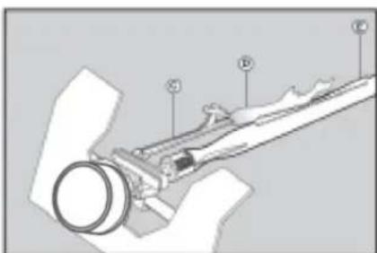

Warning : If the burner still does not light, turn the burner control dial to "OFF" and wait 5 minutes to let the gas clear before lighting again.
Warning: If the burner goes out while the grill is in operation, turn the control dial to the “OFF” position. Open the lid and wait 5 minutes before attempting to relight the BBQ.
FOOD SAFETY
Thoroughly defrost frozen meat and poultry in the refrigerator before cooking. Keep raw meat and poultry separate from cooked foods.
Always wash hands after handling raw meat and poultry, before handling any ready to eat foods.
Wipe and disinfect surfaces that have been in contact with raw meat and poultry.
When barbecuing meat and poultry, make sure the barbecue is really hot. Place the larger, thicker portions furthest away from the most intense heat to ensure thorough cooking without burning and turn regularly.
Use separate utensils for handling raw meat/poultry and cooked food on the barbecue, or wash them thoroughly between uses.
To check whether meat, particularly poultry, is cooked, pierce the flesh with a skewer or fork; the juices should run clear. Ensure the product is piping hot throughout.
TIPS FOR USE
Preheating the grill before barbecuing is important.
Follow the Lighting your BBQ instructions, then turn control dial to the “MAX” position and close the lid to preheat the grill.
This will take 10 to 15 minutes depending on conditions such as air temperature and wind. After preheating, you can adjust the control dial as desired.
Food can be barbecued with the lid up or down. Cooking with the lid down will ensure more even cooking.
For every 5 minutes that the lid is down, open the lid for 1 minute to release heat.
To save energy, we recommend:
- Minimising the time the lid is open
- Turn off the BBQ and gas supply as soon as cooking is completed
- Do not preheat the grill for longer than 10 to 15 minutes
- Do not use a higher heat setting than is required.
STORAGE
Your Gas Bottle must be stored outdoors in a well ventilated area and must be disconnected from your gas grill when not being used.
Ensure that you are outdoors and away from any sources of ignition before attempting to disconnect your gas bottle from your BBQ.
We recommend that your BBQ is stored indoors, or in a garage or shed.
When using your BBQ after a period of storage, always check for gas leaks and any obstructions in the burner before using.
CLEANING INSTRUCTIONS
Ensure the appliance is cold before cleaning.
Empty the grease tray after each use and wash in warm soapy water.
Grill trays should be cleaned by soaking and washing in warm soapy water.
The interior surfaces of the grill housing cover should also be washed with warm, soapy water. Use a wire brush, steel wool or a scouring pad to remove stubborn spots.
Periodically check the burner to see that it is free from insects and spiders which may clog the gas system and deflect the gas flow.
Ensure the venturi pipes on the burner are clean, and ensure there are no obstructions. We recommend that you use a pipe cleaner to clean the venturi pipe area.
Any modifications of this appliance may be dangerous and are not permitted.
TROUBLE SHOOTING
| PROBLEM | POSSIBLE CAUSE | PREVENTION/ SOLUTION |
| Gas leaking from cracked/cut/burned hose | Damaged hose | Turn off gas at LP tank, if hose is cut or cracked, replace hose. |
| Gas leaking from LP tank | Mechanical failure due to resting or mishandling | Turn off LP tank valve and replace. |
| Gas leaking from LP tank valve | Failure of tank valve from mishandling or mechanical failure | Turn off LP tank valve and replace. |
| Gas leaking between LP tank and regulator connection | Improper installation, connection not tight, failure of rubber seal | Turn off LP tank valve, remove regulator from cylinder and visually inspect rubber seal for damage. |
| Fire coming through control panel | Fire in burner tube section of burner due to partial blockage | Turn off control knobs and LP tank valve. After fire is out and grill is cold, remove burner and inspect for spider nests or rust. |
| Grease fire or continuous excessive flames above cooking surface | Too much grease buildup in burner area | Turn off LP Tank. Leave lid open to allow flames to die down. After cooling, clean food particles and excess grease from inside firebox area, grease cup/pan/tray, and other surfaces |
| Burner will not light using ignitor | Gas issues1. Burner not engaged with control valve of burner tubes.2. Obstruction in burner3. No gas flow4. Coupling nut ad LP tank valve not fully cleaning section of use and care connected. | Make sure valve are positioned inside of burner tubes.Ensure burner tube is not obstructed with spider webs or other material, see 3.Make sure LP tank is not empty. If LP tank is not empty, refer to “sudden drop in gas flow.Turn the coupling nut approximately one-half to three-quarters |
TROUBLE SHOOTING
| PROBLEM | POSSIBLE CAUSE | PREVENTION/ SOLUTION |
| Burner will not light using ignitor | Electrical issues:1. Electrode cracked or broken;” sparks at crack.”2. Electrode tip not in proper position3. Wire and/or electrode covered with cooking residue.4. Wires are loose or disconnected5. Wires are shorting (sparking) between ignitor and electrode.6. push button sticks at bottom sparking between ignitor and electrode | 1. Replace electrode.2. Tip of electrode should be pointing toward port hole in burner. The distance should be 1/8” to 3/16”. Adjust if necessary.3. Clean wire and or electrode with rubbing alcohol and clean swab.4. Reconnect wires or replace electrode/wire assembly.5. Replace ignitor wire6. Replace ignitor7. Inspect wire insulation and proper connection. Replace wires if insulation is broken. |
| Sudden drop in gas flow low flame | or1. Grease buildup.2. Excessive fat in meat.3. Excessive cooking temperature | 1. Clean burners and inside of grill/firebox2. Trim fat from meat before grilling. |
| Flames blow out | 1. High or gusting winds.2. Low on LP gas.3. Excess flow valve tripped. | 1. Turn front of grill to face away from wind or increase flame height.2. Refill LP tank.3. Turn control knobs to OFF, wait 30 seconds and light barbecue. If flames are still too low, reset the excessive flow safety device by turning control knobs and LP gas cylinder valve to “CLOSED” position. Disconnect regulator. Turn control knobs to “HIGH”, wait 1 minute. Then turn control knobs to OFF, and reconnect regulator and leak check connections. Slowly turn LP gas cylinder valve to “OPEN”, wait 30 seconds and then light barbecue per lighting instructions. |
| Persistent grease fire | Grease trapped by food buildup around burner system. | Turn knobs to OFF. Turn gas off at LP tank. Leave lid in open position and let fire burn out. After grill cools, remove and clean all parts. |
| Flashback... (fire in burner tube(s)) | Burner and burner tubes are blocked | Turn knobs to OFF. clean burner and/or burner tubes. See burner cleaning section of use and care manual |
| Flare-up | 1. Grease buildup.2. Excessive fat in meat.3. Excessive cooking temperature | 1. Clean burners and inside of grill/firebox2. Trim fat from meat before grilling.3. Adjust (lower) temperature |
GUARANTEE AND CUSTOMER SERVICES
This product is guaranteed for 12 months from the date of the original purchase. If any defect arises due to faulty materials or workmanship, the faulty product must be returned to the place of purchase.
Refund or replacement is at the discretion of the retailer.
The following conditions apply:
- The product must be returned to the retailer with the original proof of purchase.
- The product must be installed and used in accordance with the instructions contained in this instruction guide and any other instructions for use which are supplied.
- It must be used for domestic purposes only and for its intended use.
- This guarantee does not cover wear and tear, damage, misuse or consumable parts.
This does not affect your statutory rights.
For Customer Services & Spare Parts please call: 0330 1230 597
Or visit us at www.zanussicomfortandoutdoors.com
NOTES
NOTES
NOTES
ZANUSSI
ZANUSSI is a registered trademark used under license from AB Electrolux (publ). Made by Product Care Trading Limited, Wigan, WN2 4AY/ PCT (NI) Ltd, Belfast, BT5 5AD.
For Customer Services & Spare Parts please call: 0330 1230 597 Or visit us at www.zanussicomfortandoutdoors.com


The ‘wheelie bin’ symbol is known as the 'Crossed-out wheelie bin Symbol'. When this symbol is marked on a product/batteries, it means that the product/batteries should not be disposed of with your general household waste. Only discard electrical/electronic/battery items in separate collection schemes, which cater for the recovery and recycling of materials contained within. Your co-operation is vital to ensure the success of these schemes and for the protection of the environment. For your nearest disposal facility, visit www.recycle-more.co.uk or ask in store for details.
SEDEX – Connecting businesses and their global suppliers to share ethical data and enabling improvement in ethical performance. Visit www.sedex.org.uk for further information.
We reserve the right, due to possible changes to design, to alter the instruction manual without prior notice.
Revision 1.2

- WARNING: PLEASE ENSURE YOU HAVE READ THROUGH THE SAFETY AND OPERATING INSTRUCTIONS BEFORE USE
- CONTENTS
- SAFETY INSTRUCTIONS
- IMPORTANT SAFETY INSTRUCTIONS READ CAREFULLY AND KEEP FOR FUTURE REFERENCE
- WARNING
- DO NOT USE AN OPEN FLAME TO CHECK FOR GAS LEAKS
- SAFETY CHECKS BEFORE USE
- PARTS LIST
- BBQ ASSEMBLY
- ASSEMBLING THE STAND
- ASSEMBLING THE GRILL
- ATTACHING YOUR GAS CYLINDER
- DISCONNECTING YOUR GAS CYLINDER
- LIGHTING YOUR BBQ
- USING THE AUTOMATIC IGNITION
- FOOD SAFETY
- TIPS FOR USE
- STORAGE
- CLEANING INSTRUCTIONS
- GUARANTEE AND CUSTOMER SERVICES
- THE FOLLOWING CONDITIONS APPLY
- NOTES
- ZANUSSI
- REVISION 1.2
Brand : ZANUSSI
Model : ZGBBQ3B01-C
Category : Barbecue