
P3-35 - Receiver Phase Technology - Free user manual and instructions
Find the device manual for free P3-35 Phase Technology in PDF.


| Product Type | Amplifier / Receiver with Dolby Digital Decoding |
| Channels | 2 or 3 channel mode (switchable via dip switch 5) |
| Audio Inputs | 1x Optical (Toslink), 1x Analog (3.5mm stereo jack) |
| Speaker Outputs | Euroblock connectors for Left, Center, Right (3 channel) or Left/Right (2 channel) |
| Subwoofer Output | RCA (Sub/LINE out) with selectable crossover (120Hz internal or external) |
| Bluetooth | Built-in Bluetooth with antenna; device name: PhaseTech |
| Remote Control | Learns TV remote volume, mute, and power commands via IR receiver |
| RS232 Control | 3-pin Euroblock; Baud 115200, 8 data bits, no parity, 1 stop bit |
| Power Supply | 32V DC, 3.75A (included) |
| Equalizer | DIP switch selectable: Flat or +3dB boost for Low, Mid, High |
| Standby / Sleep Modes | Selectable via button hold; Sleep mode enables auto-on signal sensing |
| LED Indicators | White (on), Red (standby), Green (analog/PCM), Purple (Dolby), Blue (Bluetooth) |
| Mounting | Included bracket for pole or flat surface mounting |
| Box Contents | Amplifier, Bluetooth antenna, IR receiver, power supply, Euroblock connectors, mounting bracket, Velcro strips, tape disk |
| Safety Certifications | FCC Part 15, Industry Canada, CE for EU (networked standby <3W) |
Frequently Asked Questions - P3-35 Phase Technology
User questions about P3-35 Phase Technology
0 question about this device. Answer the ones you know or ask your own.
Ask a new question about this device
Download the instructions for your Receiver in PDF format for free! Find your manual P3-35 - Phase Technology and take your electronic device back in hand. On this page are published all the documents necessary for the use of your device. P3-35 by Phase Technology.
USER MANUAL P3-35 Phase Technology
The P3-35 is a 2 or 3 channel amplifier with Dolby Digital ^® decoding. It is designed to be used with either an analog or digital input from a TV or other audio source. With a digital input it automatically senses Dolby Digital and PCM and switches modes. The P3-35 takes the input signal from an audio source, decodes it and outputs either a 2 or 3 channel amplified signal to a sound bar or set of speakers. When set in the 2 channel mode it will take a stereo or multi-channel signal and mix it down to 2 output channels (left and right). When set in the 3 channel mode it will take a stereo or multi-channel signal and mix it into 3 output channels (left, right and center). In either mode there is a sub out option.
When used in place of internal TV speakers, change the TV's audio setting to external speakers. Teach the P3-35 the TV's volume codes and it seamlessly operates with no additional remotes.
Box Contents
1- Amplifier
1- Bluetooth ^® antenna
1- IR receiver with 1m cord
1-32V, 3.75A power supply
1- Six-pin Euroblock connectors
1- Three-pin Euroblock connectors
1- Mounting bracket
2- 2" Velcro strips
1- Double sided tape disk for IR receiver


Warning
Phase Technology products must be installed by a professional audio installer/contractor. For safety and optimum audio performance, installer must follow all directions issued by Phase Technology.
IMPORTANT SAFETY INFORMATION
- Read these instructions.
- Keep these instructions.
- Heed all warning.
- Follow all instructions
-
Do not use this apparatus near water.
-
Clean only with dry cloth.
-
Do not block any ventilation openings. Install in accordance with manufacturer's instructions.
-
Do not install near any heat sources such as radiators, heat registers, stoves, or other apparatus (including amplifiers) that produce heat.
-
Do not defeat the safety purpose of the polarized or grounding-type plug. A polarized plug has two blades with one wider than the other. A grounding type plug has two blades and a third grounding prong. The wide blade or the third prong are provided for your safety. If the provided plug does not fit into your outlet, consult an electrician for replacement of the obsolete outlet.
-
Protect the power cord from being walked on or pinched particularly at plugs, convenience receptacles, and the point where they exit from the apparatus.
-
Only use attachments/accessories specified by the manufacturer.
-
Use only with the cart, stand, tripod, bracked, or table specified by the manufacturer, or sold with the apparatus. When a cart
is used, use caution when moving the cart/apparatus combination to avoid injury from tip-over.
-
Unplug this apparatus during lighting storms or when unused for long periods of time.
-
Refer all servicing to qualified service personnel. Servicing is required when the apparatus has been damaged in any way, such as power-supply cold or plug is damaged, liquid has been spilled or object have fallen into the apparatus, the apparatus has been exposed to rain or moisture, does not operate normally, or has been dropped.

WARNING:
To reduced the risk of fire or electric shock, do not expose this apparatus to rain or moisture
The apparatus shall not be exposed to dripping or splashing and that no objects filled with liquids, such as vases, shall be placed on the apparatus.

DOLBY.
DIGITAL
Manufactured under license from Dolby Laboratories. Dolby and the double-D symbol are registered trademarks of Dolby Laboratories.
Mounting the P3-35

- Unpack amplifier.
Note: Follow steps 2-5 if using the mounting adapter. If not skip to step 6.

natural_image
Pure technical line drawing of a vertical support structure without any text, numbers, or symbols- Attach mounting bracket to a secure pole or surface using screws or metal strapping.

- To attach mounting bracket, remove all faceplate screws from one side. Lift faceplate and set aside.
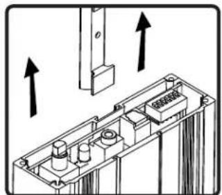
natural_image
Technical diagram of an electronic component with arrows indicating direction (no text or symbols present)- Slide mounting bracket into groove on bottom of amplifier enclosure.

- Replace faceplate screws
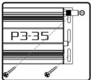
- If mounting to a flat surface use 2 screws through the mounting bracket on each end of the amp.
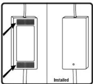
- The power supply can be attached to a mounting surface using the Velcro strips. Make sure the velcro is placed on outer most plastic portion of the power supply (do not stick it to the label).
Speaker Connections
natural_image
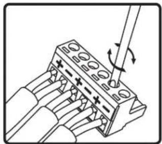
Diagram of a connector with pins and a tool, showing rotation arrows (no text or symbols)- to connect wires to the Euro-Block connector loosen the screws, insert a 1/4" in of stripped wire and tighten the screws.
Note: make sure there are no loose strands of wire.
natural_image
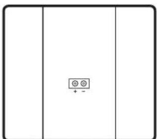
Simple diagram with a central symbol and plus/minus signs, no text or labels present1a. Make sure the + wire is connected to the plus or red terminal on your speaker and the - to the negative or black terminal on the speaker.

- For 2 channels (Stereo) connect your speakers to the 2 outer sets L and R terminals. Set dip switch 5 in the up position.

- For 3 channels connect the speakers to the two outer sets of terminal for your left and right channels and the center set for the center channel. Set dip switch 5 in the down position.
Connecting a Subwoofer

- Connect a Subwoofer to the P3-35 with an Audio RCA cable.

- To use the internal P3-35 crossover set to 120Hz set dip switch 1 to the up (Sub) position.

- To use an external Sub crossover set dip switch 1 to the down (line) position.
Connecting Your Wired Audio Source

- For digital connections connect an optical cable from your source to the optical input on the P3-35. Set dip switch 6 in the down position.
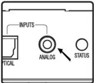
- For analog connections connect a cable from your analog source to the analog input using a stereo 1/8"mini-jack. Set dip switch 6 in the up position.
Connecting Power to the P3-35 Controlling volume using a TV remote
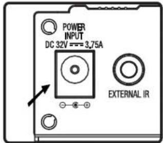
- Connect the 32v power supply barrel connector to the power input on the P3-35.

- Connect the 1/8" mini plug from the IR receiver to the External IR port on the P3-35.

- Position the IR receiver on a surface that faces out into the area you will be using the remote control. Fasten the IR receiver with the supplied two-sided tape disk.

- Turn the P3-35 on by pressing the on/off button. The LED will turn white when on.
Note: In order to program the P3-35 remote, the unit must be disconnected from an input source. It must be in the stand-by mode (white LED).

- Press and hold the on/off button on the P3-35 until it starts blinking purple (approximately 5 sec).

- Point the TV remote at the IR receiver and press the volume up button 3 times. The purple LED will blink 3 times rapidly.
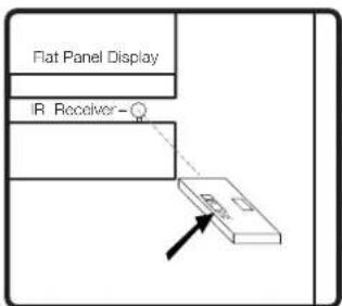
- Repeat step 5 with the volume down button. The purple LED will blink 3 times rapidly.

- Repeat step 5 with the mute button. The purple LED will blink 3 times rapidly then turn solid white. The amp is now programmed and will respond to the remote control volume commands.
RS232 Control

- Connect the RS232 control device to the RS232 port on the P3-35. Refer to Step 1 of "Speaker Connections" for instructions on wiring the Euro-Block connector.
Baud Rate 115200
Data Bits 8
Parity none
Stop bit 1
Flow Control none
- All serial commands should be sent as listed above.
| Ascii Description | Ascii Description |
| UV1 Volume up one step | GV Get Volume setting |
| UV5 Volume up five steps | SV 0-81 Send Volume setting |
| DV1 Volume down one step | AON Amp on |
| DV5 Volume down five steps | AOFF Amp off |
| MUTE 1 Mute | Reset Resets to factory default |
| MUTE 0 Unmute |
- Ascii commands above are followed by a Carriage Return.
Note: The mute command is followed by a space then the numerical value.
The SV command is followed by a space then the numerical value of 0-81 to set the relative level.
All other alphanumeric variables have no space.
Reset sets the amp in sleep mode, volume at 40 and clears the remote codes.
Pairing with a Bluetooth device

- Turn the P3-35 on by pressing the on/off button. The LED will turn white when on.
Note: Your TV remote must be programmed to work with the amp in order to establish Bluetooth pairing.

- Press and hold the mute button on the remote control for 3 seconds then release. The P3-35 LED will blink white for 1 minute or until paired.

- Select PhaseTech on your Bluetooth device to pair them.

- Bluetooth (BT) will take priority over a wired audio signal when playing BT Audio. When you stop or pause BT audio the wired audio will play.
Equalizer settings

- There are two EQ settings you can choose flat or +3dB.

- To boost the low frequencies set Dip switch 2 to the up position (+3dB)

- To boost the mid frequencies and increase intelligibility set Dip switch 3 to the up position (+3dB)

- To boost the high frequencies set Dip switch 4 to the up position (+3dB)
Standby and sleep settings
There are two modes the P3-35 can operate in; Standby and Sleep. Setting the P3-35 in the standby mode disables the auto-on input signal sensing. In this mode the P3-35 can only be turned on by pressing the Volume control On/Off switch or through RS232 control.
Setting the P3-35 in the sleep mode enables auto-on input signal sensing and will turn the P3-35 on when there is a signal present and will automatically turn off when there is no signal for 5-7 minutes.
Note: The P3-35 goes into standby mode 5 minutes after it stops sensing a signal provided the amp is set to standby mode.
The P3-35 will be switched into networked sleep mode in 5 minutes after it stops sensing a Bluetooth or wired audio signal provided the amp is set in sleep mode.
Setting the operating mode:
- With the on/off switch in the off position (Red LED).
- Press and hold the on/off switch for 10 seconds or until the LED starts blinking for 3 seconds.
- If it blinks Blue it is in Sleep mode
If it blinks Green it is in Standby mode. - To change the mode repeat step 2.
LED mode guide
Standby: RED
Power on/No signal: White
Analog/PCM: Green
Dolby: Purple
Bluetooth: Blue
Bluetooth pairing: White blinking
IR learning mode: Purple blinking
Sleep: Blue blinking
Standby: Green Blinking
Note:
P3-35's that are shipped to the EU market meet the following requirements.
The power consumption of the product in networked standby is less than 3W.
The power consumption of the product in standby mode is less than 0.5W.
This device complies with Part 15 of the FCC Rules / Industry Canada licence-exempt RSS standard(s). Operation is subject to the following two conditions: (1) this device may not cause harmful interference, and (2) this device must accept any interference received, including interference that may cause undesired operation.
Changes or modifications not expressly approved by the party responsible for compliance could void the user's authority to operate the equipment.
This equipment has been tested and found to comply with the limits for a Class B digital device, pursuant to part 15 of the FCC Rules. These limits are designed to provide reasonable protection against harmful interference in a residential installation. This equipment generates uses and can radiate radio frequency energy and, if not installed and used in accordance with the instructions, may cause harmful interference to radio communications. However, there is no guarantee that interference will not occur in a particular installation. If this equipment does cause harmful interference to radio or television reception, which can be determined by turning the equipment off and on, the user is encouraged to try to correct the interference by one or more of the following measures:
—Reorient or relocate the receiving antenna.
—Increase the separation between the equipment and receiver.
—Connect the equipment into an outlet on a circuit different from that to which the receiver is connected.
—Consult the dealer or an experienced radio/TV technician for help.
Under Industry Canada regulations, this radio transmitter may only operate using an antenna of a type and maximum (or lesser) gain approved for the transmitter by Industry Canada. To reduce potential radio interference to other users, the antenna type and its gain should be so chosen that the equivalent isotropically radiated power (e.i.r.p.) is not more than that necessary for successful communication.
To satisfy FCC / IC RF exposure requirements, a separation distance of 20 cm or more should be maintained between the antenna of this device and persons during device operation.
To ensure compliance, operations at closer than this distance is not recommended.
This radio transmitter (identify the device by certification number, or model number if Category II) has been approved by Industry Canada to operate with the antenna types listed below with the maximum permissible gain and required antenna impedance for each antenna type indicated. Antenna types not included in this list, having a gain greater than the maximum gain indicated for that type, are strictly prohibited for use with this device.
Gain of antenna: 2.0dBi max.
Type of antenna: Omni-directional
Impedance of antenna: 50ohm
Brand : Phase Technology
Model : P3-35
Category : Receiver