24DMS4G113 - Cooker MIDEA - Free user manual and instructions
Find the device manual for free 24DMS4G113 MIDEA in PDF.

| Product type | Freestanding gas hob and electric oven cooker |
| Brand | Midea |
| Model | 24DMS4G113 |
| Energy source | Gas (hob) + Electric (oven) |
| Power supply voltage | 220-240 V |
| Frequency | 50-60 Hz |
| Total electric power | 3.0 kW |
| Compatible gas types | Natural Gas (NG) and ULPG |
| Gas pressure (Natural Gas) | 1.0 kPa |
| Gas pressure (ULPG) | 2.75 kPa |
| Total heat input (Natural Gas) | 29.2 MJ/h (772 l/h) |
| Total heat input (ULPG) | 27.6 MJ/h (729 l/h) |
| Number of gas burners | 4 (Rapid, Semi-rapid, Auxiliary, Additional semi-rapid) |
| Oven type | Electric oven with multiple heating modes |
| Oven functions | Top heat, bottom heat, grill, convection, rotisserie (optional), oven light |
| Oven temperature range | 50 – 250 °C (baking), Broil setting |
| Timer | Minute minder (120 min max) |
| Safety features | Anti-tip bracket, safety valve, flame failure device (likely) |
| Anti-tip bracket included | Yes |
| Adjustable feet | Yes (for levelling) |
| Dimensions (approx.) | 600 mm (W) x 600 mm (D) x 850 mm (H) |
| Weight (approx.) | 50 kg |
| Accessories included | Baking tray, wire rack, anti-tip bracket, pressure regulator, burner caps |
| Maintenance interval | Recommended service every 2 years |
Frequently Asked Questions - 24DMS4G113 MIDEA
User questions about 24DMS4G113 MIDEA
0 question about this device. Answer the ones you know or ask your own.
Ask a new question about this device
Download the instructions for your Cooker in PDF format for free! Find your manual 24DMS4G113 - MIDEA and take your electronic device back in hand. On this page are published all the documents necessary for the use of your device. 24DMS4G113 by MIDEA.
USER MANUAL 24DMS4G113 MIDEA
Free-standing gas hotplates and electrical oven Instruction Manual
24DMS4G113
natural_image
Line drawing of a standard open oven with six burners (no text or symbols)KEEP THESE INSTRUCTIONS IN A SAFE PLACE
Product picture only for reference
Thank you for choosing us! Please read all instructions before using this appliance. This book contains valuable information about operation, care and service. Keep it in a safe place for future reference. Should the appliance be sold or transferred to another owner, or should you move house and leave the appliance, always ensure that the book is supplied with the appliance so that the new owner can be acquainted with the functioning of the appliance and relevant warnings. Important
Safety Warning
THESE WARNINGS ARE PROVIDED IN THE INTEREST OF SAFETY, PLEASE READ THEM CAREFULLY BEFORE INSTALLING OR USING THE APPLIANCE
- To maintain the EFFICIENCY and SAFETY of this appliance, we commend:
-
Call the Service Centers authorized by the store where you buy the cooker.
● Always use original Spare Parts -
This appliance is intended for non-professional use within the home.
-
Before using the appliance, read the instructions in this owner's manual carefully, since you should find all the instructions you require to ensure safe installation, use and maintenance. Always keep this owner's manual close to hand since you may need to refer to it in the future.
-
After removing the packaging, check that the appliance is not damaged. If you have any doubt, do not use the appliance. Contact your nearest Service Centre of the store where you buy the appliance. Never leave the packaging components plastic bags, foamed polystyrene, nails, etc.) within the reach of children since they are a source of potential danger.
-
The appliance must be installed only by a qualified person in compliance with the instructions provided. The manufacturer declines all responsibility for improper installation which may harm persons and animals and damage property.
-
This appliance designed to be used by children aged above 8 years. Person with reduced physical, sensory or mental capabilities or lack of experience and knowledge shall be under supervision and instructed concerning use of the appliances in a safe way and understand the hazards involved when using the appliance.
-
The electrical safety of this appliance can only be guaranteed if the cooker is correctly and efficiently earthed, in compliance with current regulations on electrical safety. Always ensure that the earthing is efficient if you have any doubts call in a qualified electrician to check the system. The manufacturer declines all responsibility for damage resulting from a system which has not been earthed.
-
Check that the electrical capacity of the system and sockets will support the maximum power of the hob, as indicated on the rating label. If you have any doubts call in a qualified technician
- When the cooker is first used an odor may be emitted, this will cease after a period of use. When first using the cooker ensure that the room is well ventilated e.g., open a window or use an extractor fan and that persons who may be sensitive to the odor avoid any fumes. It is suggested that any pets be removed from the room until the smell has ceased. This odor is due to temporary finish on oven liners and element sandal so any moisture absorbed by the insulation.
- Ensure that the appliance is switched off before maintenance by switching off the main switches and turning all knobs to OFF position.
- The openings and slots used for ventilation and dispersion of heat on the rear and below the control panel must never be covered.
- The user must not replace the supply cable of this appliance. Always call an after-sales servicing Centre authorized by the seller in the case of cable damage or replacement.
- This appliance must be used for the purpose for which it was expressly designed. Any other use is considered to be improper and consequently dangerous. The manufacturer declines all responsibility for damage resulting from improper and irresponsible use.
- A number of fundamental rules must be followed when using electrical appliances. The following are of particular importance do not touch the appliance you're your hands or feet are wet do not use the appliance bare footed. Never allow the Mains Cable to be stretched, pulled or damaged if the Cooker is moved for cleaning etc. Do not use the cooker if the Mains Cable is damaged, consult a qualified electrician. Do not allow the cooker to be used unsupervised by children or persons unfamiliar with it.
- Always switch off the electrical supply to the cooker and allow it to cool down before carrying out any cleaning operations etc.
- Danger of fire: do not store items on the cooker surfaces.
- To avoid accidental spillage do not use cookware with uneven or deformed bottoms on the burners or on the electric plates.
- Special care should be taken when using chip pans etc. in order to avoid splashing or spillage of hot oil. They should not be used unattended since over heated oil may boil over and could also ignite.
- Parts of this appliance, cooking surfaces, retain heat for considerable periods after switching off. Care should, therefore, be taken when touching these areas before they have completely cooled down.
- Never use flammable liquids such as alcohol or gasoline, etc. near the appliance when it is in use.
-
When using small electrical appliances near the hob, keep the supply cord away from the hot parts.
-
Make sure the knobs are in its “OFF” position when the appliance is not in use. Also make all potentially dangerous parts of the appliance, safe, above all for children who could play with the appliance.
- When the appliance is in use the heating elements and some parts of the oven door become extremely hot. Make sure you don't touch them and keep children well away.
- If you use the power cable for single phase, the minimum cross-sectional area is 10mm ^2 . For three phases the minimum cross sectional area is 2.5 mm ^2
- You must grill with closed door.
- DO NOT USE OR STORE FLAMMABLE MATERIALS IN THE APPLIANCE STORAGE DRAWER OR NEAR THIS APPLIANCE. DO NOT SPRAY AEROSOLS IN THE VICINITY OF THIS APPLIANCE WHILE IT IS IN OPERATION.
- DO NOT PLACE ARTICLES ON OR AGAINST THIS APPLIANCE.
- DO NOT MODIFY THIS APPLIANCE.
- DO NOT USE THIS APPLIANCE AS A SPACE HEATER.
- Gas installation must be made in accordance with AS/NZS 5601. Also refer to rangehood manufacturers recommendation.
- Special conditions which shall be avoided, e.g. marine environment, and any conditions necessary to ensure optimum performance.
- Where necessary, a safe purge before the appliance is re-lit.
Safety reminding
natural_image
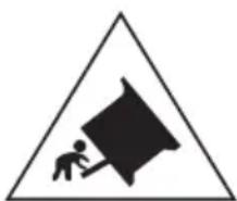
Warning symbol of a person pushing a large block inside a triangle (no text or numbers)Caution, possibility of tilting
natural_image
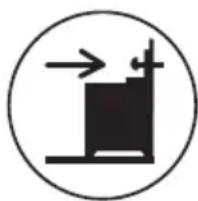
Simple black-and-white diagram of a container with arrows indicating flow or movement (no text or symbols)Anti-tip restraints
WARNING: In order to prevent tipping of the appliance, this stabilising means must be installed. Refer to instructions for installation.
Safety
For the user and installer
- Disconnect the range before cleaning or doing maintenance.
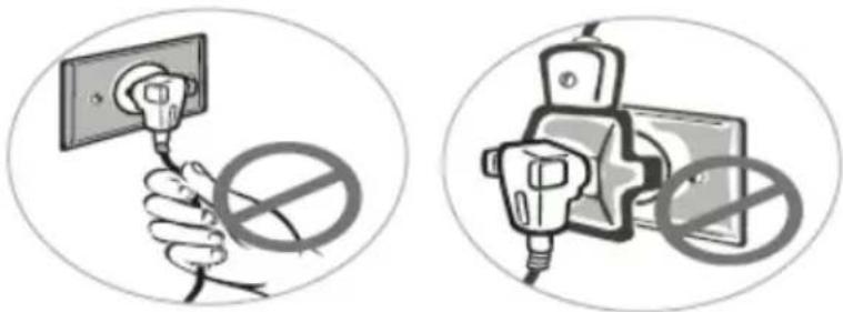
- Never unplug the range by pulling on the power cord. Do not manipulate your gas range plug. Do not bite, twist or tie the power cord.
-
It is dangerous to modify your gas range specifications and characteristics.
Do not install your gas range on top of the power cord. -
Connect the range to its own outlet. Do not use an extension cord or adaptor plug. To avoid any accident, before replacing the light lamp, turn off the cook top burners
natural_image
Two circular illustrations showing a hand holding an electrical socket with a prohibition symbol, next to a plug and switch (no text or labels present)Care with food and cookware
- To handle or remove food, please use the cooking gloves.
- Never leave clothes or flammable materials near the burner when the range is in use. When using frying oil or butter additional care must be taken since these products are flammable.
- Do not use the oven to store utensils, especially those containing residues or large quantities of oil or fat.
- Containers with curved bases or salient edges must not be used since they can be easily destabilized when moved.
- The handle of the utensil should be positioned so that it is turned inward.

natural_image
Illustration of a cooking pot with handles and a base, labeled 'Wrong' below (no other text or symbols)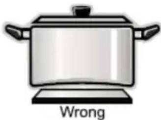
text_image
Wrong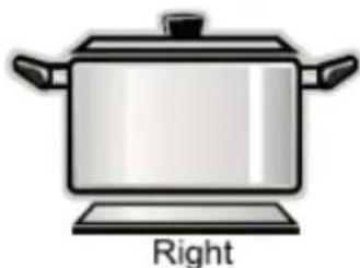
natural_image
Illustration of a cooking pot with handles and a labeled 'Right' text below (no other symbols or text)| Installation accessories | |||
| Accessory Name | Image (for reference only, physical unit maybe different) | Quantity | Application |
| Anti-tilt Bracket | 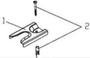 | 1 | To prevent tipping of the cooker. |
| Washer Gas-type fitting (G1-2 R1/2 Φ 21.0 mm) | 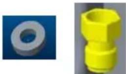 | 11 | Provided with pressure regulator. |
| Natural gas regulator (Rp 1/2 NG 1.0kPa) |  | 1 | Pressure regulator for natural gas. |
| Burner caps | 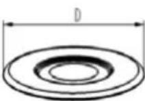 | D=134.4mm | 1# Outer burner cap1# Inner burner cap2# Burner cap3# Burner cap4# Burner cap |
| D=65.7mm | 1 | ||
| D=100mm | 1 | ||
| D=75mm | 2 | ||
| D=55mm | 1 | ||
| Installation & Operation Instructions |  | 1 | User Manual |
| Pressure test connector (For ULPG) | 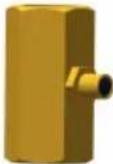 | 1 | Test gas pressure |
| Rating label |  | 1 | Rating label |
Installing instruction
Before installing
Read the following information about the appliance and the guidelines for ventilation.
Appliance Unpacking
Check the condition of the appliance after unpacking it.
Do not connect the appliance if it has been damaged in transport.
Dispose of packaging in an environmentally-friendly manner.
Guideline for ventilation
This appliance may only be set up in a sufficiently ventilated room and according to the applicable regulations and ventilation requirements.
Ventilation must be in accordance with AS/NZS 5601 - Gas Installations.
Be sure that there is a good air flow, keeping natural air ventilation through a window or door by installing a range hood to extract the air. If ventilation is not good, this might cause lack of oxygen, which is dangerous for your health and the gas performance. If the gas range will be working for a long period of time, a extra ventilation will be necessary to increase the air flow.
Do not install in a bed-sitting room, a bathroom or shower room. If there is another fuel burning appliance in the same room, a higher level of ventilation will be required.
In addition to the above, during prolonged use, opening a window in the same room is recommended. This will avoid the build up of excessive moisture and condensation.
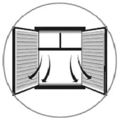
natural_image
Diagram of a double door with airflow arrows indicating fluid or airflow direction (no text or symbols)Installation
This appliance is always supplied with a set of adjustable feet and, depending on the model, with a
splash guard. The appliance may also be used without the splash guard.
Fitting the adjustable feet Before hand:
- Remove all parts that are not permanently fixed, especially the pan supports and burners.
- Remove the accessories from the oven. Proceed as follows:
- Tilt the appliance by raising one side slightly from the floor.
- With the plates in position, screw the adjustable feet into the mounting holes on the underneath of the appliance.
- Repeat the process on the other side. You can make the final adjustments to the feet in order to level the appliance once the gas and electricity supply have been connected. If it is necessary to pull the appliance, screw the adjustable feet in fully. Make the final settings
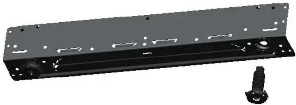
natural_image
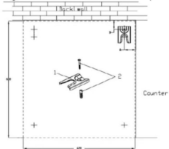
3D rendering of a black metal frame with bolt holes and a separate screw (no text or symbols)In order to prevent tipping of the appliance, this stabilizing means must be installed. Using ground screw 2 to mount the anti-title bracket 1 on the ground showed as the below picture .
text_image
Back wall Counter 1 2 600- Anti-title bracket 2. Ground screw
| Product Model | Height(mm) | A(mm) | B(mm) |
| 20 | 850 | 50 | 50 |
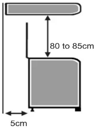
Gas appliance installation
1> Leave at least 80 to 85cm between the top of the gas appliance and any cabinet or appliance hood install above prepared to be installed built in.
2>Leave at least 5cm in the back and 2cm each side of the gas appliance to allow the heat to get out.
3>When installing the oven, be sure not to block the oven exhaust port.
4>After installation, please paste the rating label on visible location or nearby.
text_image
80 to 85cm 5cmElectrical connection
Only a licensed expert may connect the appliance. The appliance must be installed according to the most recent IEE regulations (Institute of Electrical Engineers). The appliance could become damaged if incorrectly connected. Make sure the voltage of the power supply corresponds to the specified value on the rating plate. The rating plate can be found on the inside of the storage compartment flap. Ensure that the power supply is properly earthed and that the fuse and the wiring and piping system in the building can withstand the load from the appliance. It is recommended that you configure the circuit for the appliance to 16 A. When you route the mains cable, make sure that:
- the cable is not trapped or squashed.
- the cable does not come into contact with sharp edges or cutting edges.
- the cable does not come into contact with parts that can reach temperatures of more than 50^ above room temperature.
Connecting the mains cable
Where the appliance is directly connected to the power supply, an all-pole isolating switch with a contact gap is required. Complete disconnection in compliance with the conditions specified in overvoltage category III must be guaranteed. The earth cable is excluded from this.
Gas connection
The appliance must be connected in accordance with the currently applicable regulations. Before installing the appliance, check that the local conditions (type of gas and pressure) are compatible with the appliance settings. The permissible appliance settings can be found on the rating plate. Connection to the gas lines and seal fitting must be carried out professionally according to the currently applicable standards.
Gas connection on the appliance
The gas connection is located at the rear left of the appliance.
Connecting pieces
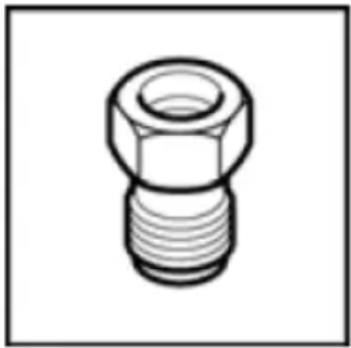
natural_image
Technical line drawing of a mechanical connector (no text or symbols)NG corrugated tube union(and seal)
● An inlet manifold extension pipe must be fitted to the appliance.
- Ensure that the pipe is connected using the washer provided and that the bracket is screwed to the appliance as shown in the diagram below.
- Fit the supplied pressure regulator (for Natural gas) using the NG test point adaptor and washer to the inlet manifold. Ensure the arrow is pointing towards the appliance and that pressure testpoint is accessible from the final position.
- Push the cooker back and install the anti-tilt bracket.
- Connect the appliance to the consumer piping outlet using only fixed piping.
This final connection is made when the product is pushed back into position by access under the cooker.
- 4 burner models: set the burner pressure to 2.75 kPa for ULPG, set the burner pressure to 1 kPa for Natural Gas. For commissioning of the appliance with the regulator for Natural Gas, the test point pressure should be 1.00 kPa with all burners operating on HIGH.
- Apply a manometer to the test nipple and reset the regulator if necessary. Do not forget to replace the test nipple screw and to leave the instruction book with the user.
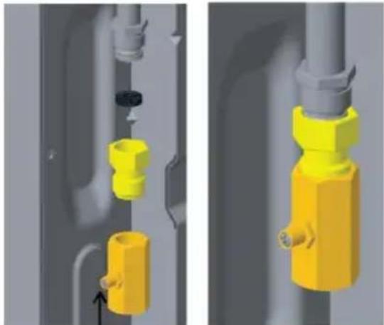
Test point for Natural gas
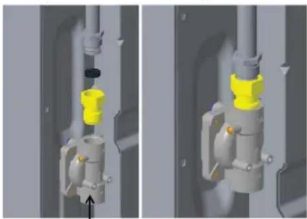
natural_image
3D mechanical assembly diagram showing two views of a valve component with yellow and gray parts, no text or symbols present.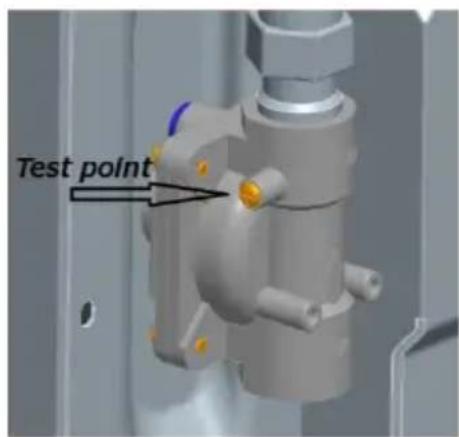
text_image
Test pointTest point for ULPG gas
natural_image
3D mechanical assembly diagram showing yellow and gray components with a black circular component, no text or symbols presentWARNING:
This appliance has to be installed as per AS/NZS 5601 and if a hose connectino is made, hose assembly must:
1) Be certified as conforming with AS/NZS 1869, and be Class B or Class D.
2) Diameter 10mm (minimun).
3) Length 1000mm (maximum).
WARNING:
Ensure hose assembly is restrained from accidental contact with the flue outlet of an under bench oven.
The hose assembly should be kept clear of the floor when the appliance is in the installed position.
Safety valve
The installation of a safety valve for opening and closing the gas supply is a compulsory requirement. Fit the safety valve between the gas connecting line to the appropriate room and the hob. Ensure unhindered access to this valve.
Checking for leaks
After connecting the gas line, check the connections for leaks using soapy water.
Initial use
Switch the appliance on as described in the instruction manual. Light all the burners and check that the flames remain stable at both the high and low settings.
Converting the gas type
If the appliance is not already set up for the existing type of gas, the appliance must be converted. The conversion to a different type of gas must be carried out by an authorised expert in accordance with the applicable regulations.
In order to convert to a different type of gas, the nozzles must be replaced and the low flame and primary air may have to be adjusted.
Replacing the nozzles (Hotplate burners)
- Remove the burner caps (A) and burner (B) from the burners (C).
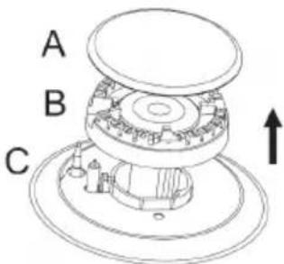
text_image
A B C- Remove the nozzle (D) and replace it with an appropriate nozzle for the new type of gas.
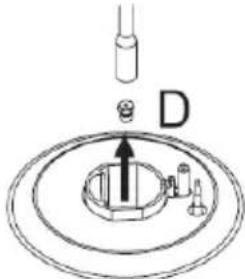
text_image
D-
Replace the gas label with the new gas label that was supplied with the nozzle set.
-
Place each burner cup(B) on the burner(C).
Setting the minimum flow
-
Switch on the gas burner.
-
Turn the control knob for the gas burner towards the small flame setting
-
Remove the control knob for the gas burner.
-
Adjust the internal setting screw until as table flame is burning correctly. Loosen the adjuster screw to increase the gas flow or tighten it to decrease the gas flow.
Check that the flame does not go out when the gas flow is quickly changed between maximum and minimum, and vice versa. The setting is correct when the height of the small flame is approx. 3 to 4mm.
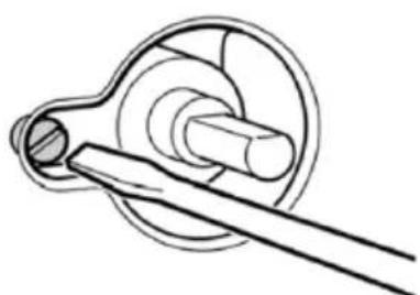
natural_image
Technical line drawing of a mechanical component with a shaft and housing (no text or symbols)Positioning and leveling
Positioning the appliance
When installing the appliance, make sure that there is enough space in the final installation location to pull the appliance forwards for cleaning and maintenance work. The ground underneath must be hard and stable. The wall immediately behind the appliance must be made from non-flammable material, e.g. tiles. If you need to pull the appliance in order to position it, make sure that the adjustable feet are screwed in fully.
Levelling the appliance
Level the appliance once all other work has been completed. To do this, turn the adjustable feet.
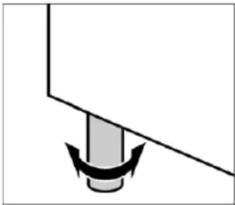
natural_image
Simple diagram of a mechanical component with a curved arrow indicating force or motion (no text or symbols)Using instruction
Your new appliance
Get to know your appliance. You will find information about the control panel and hob, as well as the oven, types of heating and accessories.
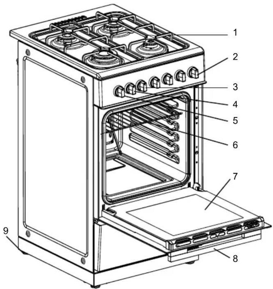
text_image
Technical diagram of a portable oven with numbered parts for identification- Pot rack
- Burners knobs
- Timer knob
- Function knob
- Temperature knob
- Baking rack
- Oven door
- Door handle
- Base
The control panel
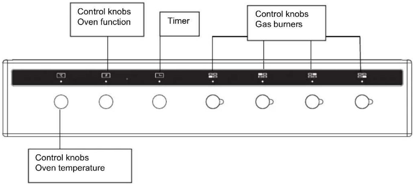
flowchart
graph TD
    A["Control knobs\nOven function"] --> B["Box 1"]
    C["Timer"] --> D["Box 2"]
    E["Control knobs\nGas burners"] --> F["Box 3"]
    G["Control knobs\nOven temperature"] --> H["Box 4"]
    I["Box 5"] --> J["Box 6"]
    K["Box 7"] --> L["Box 8"]
    M["Box 9"] --> N["Box 10"]
The hob
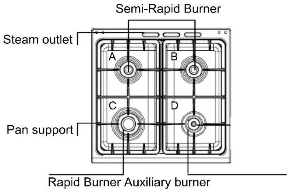
text_image
Semi-Rapid Burner Steam outlet A B C D Pan support Rapid Burner Auxiliary burnerControl knobs for gas burners
Adjust the heat setting of the gas burners using the control knobs. The symbol above the control knob shows you to which gas burner the control knob belongs.
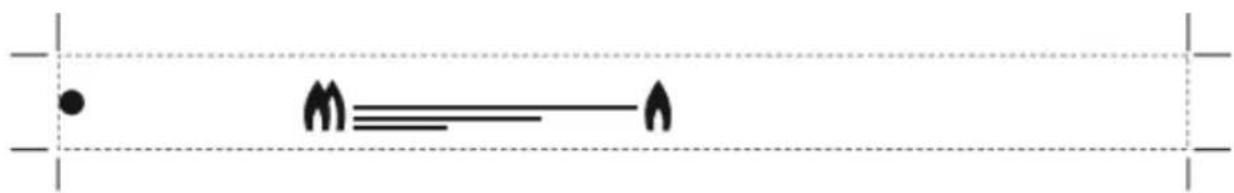
natural_image
Pure diagram with horizontal lines and symbols, no readable text or labelsOperating gas burners
Make sure that the burner lid always sits exactly on top of the burner cup. The slots on the burner cup must be open. All parts must be dry.
Switching on the gas burner
-
Press the control knob for the required burner and turn it to position
. The gas burner ignites. Keep the control knob pressed for a few seconds until the flame stabilises. And push the ignition button at the same time (for some models are auto-ignition). -
Adjust the burner to the desired flame setting.
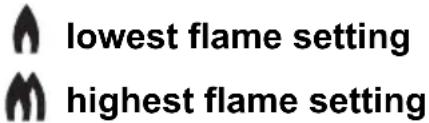
text_image
lowest flame setting highest flame setting*Shut down where incorrect procedures can result in a hazardous condition.
Function button for ignition

natural_image
Simple black five-pointed star outline on white background (no text or symbols)Ignition can be manual or auto.
Steam outlet Risk of burns.
Hot air from the oven escapes out of the steam outlet on the hob. Never touch the steam outlet. Please note that, in the case of appliances with a hob cover, the burners in the oven may also only be switched on if the hob cover is open.
Control knob for oven
Use this control knob to the function


Off
| Symbol | Power | Function |
 | 25 The lamp work | |
 | 58 The lamp and circulation motor work | |
 | 2600 | The top heating element ,grill heating element,circulation motor ,lamp and rotary motor work |
 | 2580 | The top heating element ,grill heating element,circulation motor ,lamp work |
 | 1629 | The grill heating element, lamp and rotary motorwork |
 | 2108 | The top heating element, bottom heatingelement ,lamp and circulation motor work |
 | 2075 | The top heating element, bottom heating elementand lamp work |
 | 1125 The bottom heating element and lamp work | |
 | 2058 | The turbo heating element, lamp and circulationmotor work |
And then, use this control knob to the temperature

Broil
200
150
100
50 Baking

OFF
Baking
50 - 200
Broil
Oven electric on, the minimum temperature
Oven electric on, temperature
Oven electric on, the maximum temperature
There is a limit stop between settings 250 and 0.
Do not turn the knob beyond this point.
Operate your oven
Please note that, in the case of appliances with a hob cover, the burners in the oven may only be switched on if the hob cover is open.
Switching on the oven lighting
Press down the function button for the oven lighting until it locks into place. The oven lighting switches on.
Switching off the oven lighting
Press down the function button for the oven lighting until it releases. The oven lighting switches off.
The minute minder
The minute minder is a countdown timer which emits an audible signal when the cooking time has elapsed. The minute minder runs independently of the oven.
Control knob for minute minder
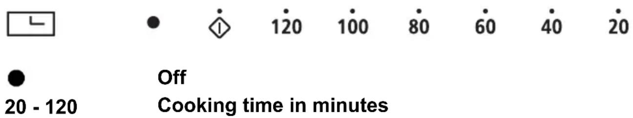
text_image
20 - 120 Off Cooking time in minutesSetting a cooking time
Turn the control knob once round clockwise, as far as the limit stop, and then turn it anti-clockwise to set it to the required time.
The cooking time has elapsed
A signal sounds once the time has elapsed.
Oven Control
The oven temperature setting knob can only be rotated clockwise from the OFF position. Turn oven function control knob to select the cooking function, meanwhile turn the timer (for the model with timer) to set the cooking time you want. Then turn oven temperature control clockwise to the required oven temperature. The red oven temperature pilot light will immediately illuminate and will automatically go off when oven temperature reaches the temperature setting.
Accessories
The accessories can be inserted in the oven in 5 different shelf positions. You can pull the accessories two-thirds of the way out without them tipping. This allows meals to be removed easily. You can buy accessories from the after-sales service or from specialist retailers.
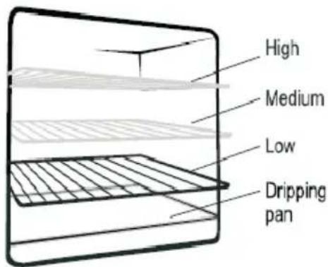
text_image
High Medium Low Dripping panAccessory Description
natural_image
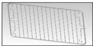
Pure technical diagram of a rectangular grid pattern without any text, numbers, or symbolsBaking and roasting shelf
For ovenware, cake tins, roasts, grilling and frozen meals.
natural_image
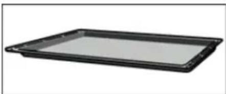
Black rectangular tray with a flat top, isolated on white background (no text or symbols)Enamelled baking tray
For moist cakes, pastries, frozen meals and large roasts. Can also be inserted underneath the wire rack or rotary spit and used as a drip tray to collect fat.
natural_image
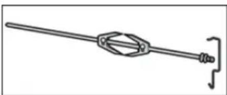
Pure mechanical linkage diagram without any text, numbers, or symbolsRotisserie (option)
For roasts and large pieces of poultry. Use only in combination with the enamelled baking tray.
The storage compartment (for some models)
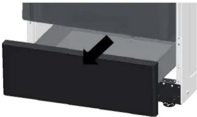
natural_image
3D rendering of a mechanical assembly with a black rectangular component and an arrow indicating direction (no text or symbols)Open the storage compartment by folding down the fascia panel. This compartment can be used to store food or other things.
Risk of fire.
Never leave combustible items in the storage compartment.
Before using for the first time
Please read the following instructions before using your appliance for the first time. Remove the appliance packaging and dispose of this appropriately.
Cooking compartment initial cleaning
Remove the accessories from the cooking compartment. Completely remove any leftover packaging, e.g. small pieces of polystyrene, from the cooking compartment. Some parts are covered with a protective film. Remove this film.
- Clean the outside of the appliance with a soft, damp cloth.
-
If the hook-in racks have already been fitted, unhook and remove them. For information on removing the racks, see the section "Removing and refitting hook-in racks."
-
Clean the cooking compartment with warm soapy water.
Rinsing cooking compartment after initial cleaning
Clean the cooking compartment with hot soapy water. Refit the hook-in racks.
Cleaning the burner lids and cups
Proceed as follows:
- Clean the burner lids (A) and cups (B) with water and washing-up liquid.
- Dry the parts off well.
- Place the burner sprayer (B) on the burner (C).
- Place the burner lid (A) exactly on top of the burner cup (B).
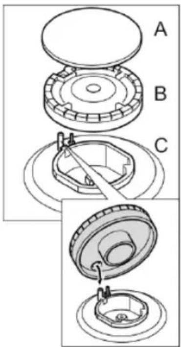
text_image
A B CCleaning accessories
Before using the accessories, clean them thoroughly using a cloth and warm soapy water.
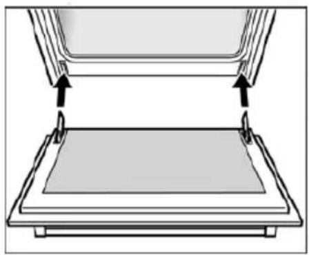
Cleaning the interior glass of the oven
The interior glass of the oven door can be removed: with the door in the semi-open position, use both hands to remove the glass .After cleaning, refit the glass in reverse order.
Note: In some models, the glass is screen printed. In this case, when refitting the glass make sure the screen printed part is legible when the oven door is opened.
Warning
Never use high-pressure cleaners or steam jets.
Risk of short circuit.
Never use caustic or abrasive cleaning agents. These could damage the surface. If such an agent gets on the front of the appliance, wipe it off immediately with water. Do not clean any surfaces of the appliance while they are hot.
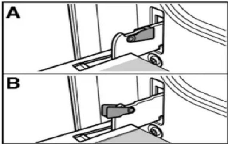
Removing and fitting the appliance door
You can remove the appliance door for easier cleaning.
The hinges of the appliance door are each secured by a locking lever. When the locking lever is folded in (A), the appliance door is secured. It cannot be unhinged. If the locking lever is open (B), only the hinge is secured, and you can remove the appliance door.
natural_image
Two-panel diagram showing mechanical components in section A and B, with no visible text or symbols.Risk of injury.
Do not reach inside the hinge.
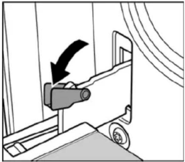
Removing the appliance door
Proceed as follows:
-
Open the appliance door.
-
Lift up the locking levers on both sides.
-
Close the appliance door until you feel resistance at an angle of around 15^ (in relation to the closed appliance door).
-
Grip the door on either side with both hands.
-
Close the appliance door a little further.
-
Lift the door upwards and at an angle to remove it.
Do not disassemble the door.
natural_image
Diagram of a car being pulled into a lift, showing the blade and wheel (no text or symbols)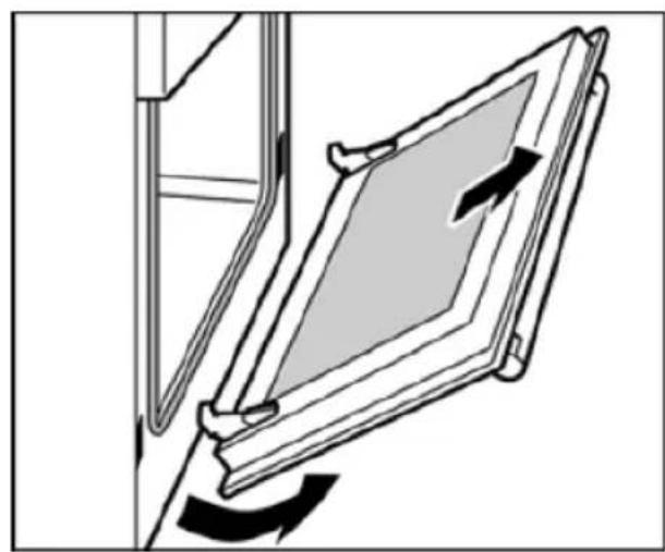
natural_image
Diagram of a door frame with directional arrows indicating movement or force (no text or symbols)Fitting the appliance door
-
Hold the appliance door at an angle.
-
Insert both hinges, left and right, into the supports.
-
Position the door so that the hinge grooves engage on both sides.
-
Open the appliance door.
-
Fold in the locking levers on both sides.
-
Close the appliance door.
natural_image
Diagram of a mechanical assembly with two components and directional arrows indicating movement (no text or symbols)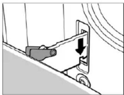
natural_image
Diagram of a mechanical device with a downward arrow indicating motion or force, no text or symbols present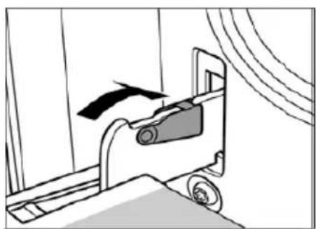
natural_image
Diagram of a mechanical device with a black arrow indicating motion, no text or symbols presentRemoving and inserting the hook-in racks
You can remove the hook-in racks in order to clean them separately. The hook-in racks are all fixed to the walls of the cooking compartment at four points.
Removing the hook-in racks
To remove the hook-in racks, proceed as follows:
- Undo the screw on the bottom the hook-in rack. The lower hooks of the hook-in rack are released.
- Take hold of the top of the hook-in rack and screw on the screw on the bottom the hook-in rack again.

natural_image
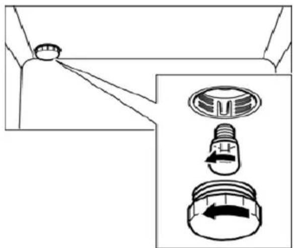
Technical line drawings of a device showing internal structure and mounting points (no text or symbols)Replacing the oven light bulb
If the oven light bulb fails, it must be replaced. Replacement heat-resistant bulbs can be obtained from the after-sales service or from specialist retailers. Please specify the SN number of your appliance. Do not use any other type of bulb.
Proceed as follows:
- Switch off the relevant circuit breaker.
- Open the appliance door.
- Lay a tea towel in the cooking compartment if it is cold to prevent damage.
-
Unscrew the glass cover from the bulb inside the cooking compartment by turning it anti-clockwise.
-
Replace the bulb with one of the same type. Voltage: 230 V Power: 25 W Thread: E14 Temperature resistance: 300°C
natural_image
Diagram showing a mechanical component with three views: top view, side view of a circular component with internal features, and bottom view with directional arrows (no text or symbols)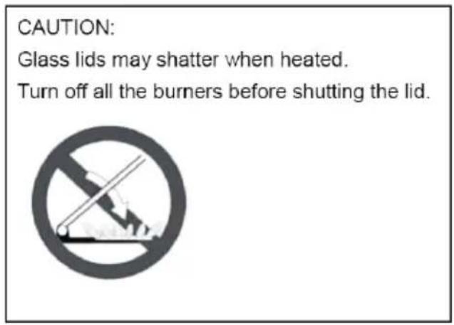
text_image
CAUTION: Glass lids may shatter when heated. Turn off all the burners before shutting the lid.-
Screw on the glass cover again.
-
Remove the tea towel and switch the circuit breaker back on. Press the function button the oven lighting until it locks into place in order to check whether the oven lighting is working properly.
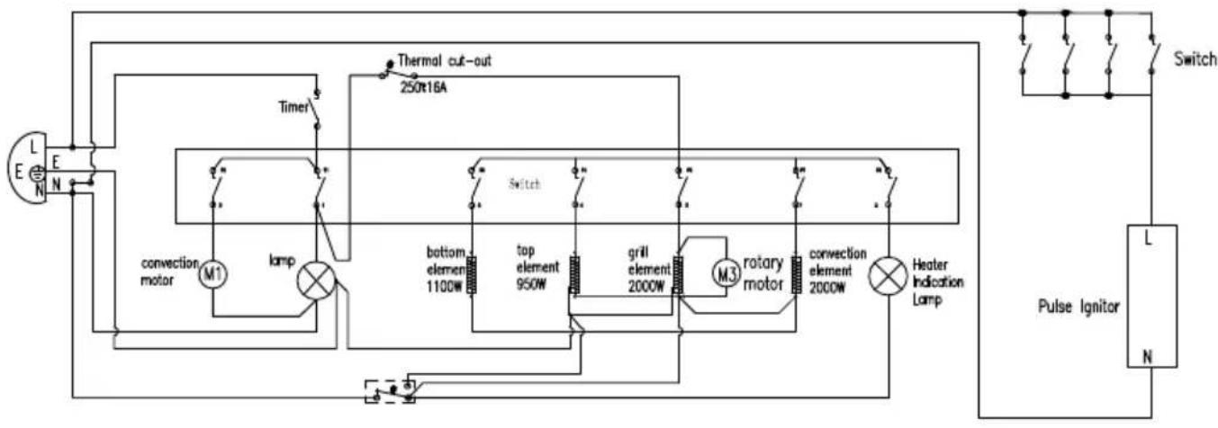
flowchart
graph TD
    A["L E N"] --> B["convection motor"]
    B --> C["m1"]
    C --> D["lamp"]
    D --> E["top element 950W"]
    E --> F["grill element 2000W"]
    F --> G["m3"]
    G --> H["rotary motor"]
    H --> I["convection element 2000W"]
    I --> J["Heater Indication Lamp"]
    J --> K["Pulse Ignitor"]
    K --> L["L N"]
    M["Thermal cut-out 250x16A"] --> N["Switch"]
    O["Timer"] --> P["Switch"]
    Q["Power Supply"] --> R["Switch"]
Aftersales service
Our after-sales service is there for you if your appliance needs to be repaired. You will find the address and telephone number of your nearest after-sales service centre in the phone book. The after-sales service centres listed will also be happy to give you the details of an after-sales service point near you.
Technical data
| COMPANY | Guangdong Midea Kitchen Appliances Manufacturing Co., Ltd | |
| ADDRESS | No.6 YongAn Road, Beijiao, Shunde, Foshan, Guangdong, China | |
| PRODUCT | GAS/ELECTRIC COOKER | |
| MODEL NO. | 24DMS4G113 | |
| VOLTAGE/FREQUENCY | 220-240V,50-60Hz | |
| ELECTRIC POWER 3.0kW | ||
| TYPES OF GAS | Natural Gas | |
| GAS PRESSURE | 1.0 kPa | |
| TOTAL HEAT INPUT | 29.2MJ/h 772l/h (hotplate burners) | |
| INJECTOR SIZE | A:1.2mm 7.1MJ/h B | 1.2mm 7.1MJ/h |
| C: 1.5mm 11.0MJ/h | D: 0.9mm 4.0MJ/h | |
| COMPANY | Guangdong Midea Kitchen Appliances Manufacturing Co., Ltd | |
| ADDRESS | No.6 YongAn Road, Beijiao, Shunde, Foshan, Guangdong, China | |
| PRODUCT | GAS/ELECTRIC COOKER | |
| MODEL NO. | 24DMS4G113 | |
| VOLTAGE/FREQUENCY | 220-240V,50-60Hz | |
| ELECTRIC POWER 3.0kW | ||
| TYPES OF GAS | ULPG | |
| GAS PRESSURE | 2.75 kPa | |
| TOTAL HEAT INPUT | 27.6MJ/h 729l/h (hotplate burners) | |
| INJECTOR SIZE | A: 0.73mm 6.5MJ/h | B: 0.73mm 6.5MJ/h |
| C: 0.95mm 11.0MJ/h | D: 0.53mm 3.6MJ/h | |
Nozzles
| Model | 24 DMS4 G1 1 3 | SN: | |||
| Power supply 220 | 240V,50 60Hz 3.0kW | ||||
| Heat input (MJ/h) |  | Total | |||
| 7.1 7. | 1 11 4 29. | 2 | |||
| Nozzle diameter (mm) | 1.2 1.2 | 1.5 0.9 / | |||
| ADJUSTED FOR NG 1.00kPa | Replacement of the nozzles must be performed by a qualified person.Once the nozzles have been replaced this label must to affixed to the name plate of the appliance | ||||
| Model | 24 DMS4 G1 1 3 | SN: | |||
| Power supply 220 | 240V,50 60Hz/3.0kW | ||||
| Heat input(MJ/h) | Total | ||||
| 6.5 6. | 5 11 3.6 | 27.6 | |||
| Nozzle diameter(mm) | 0.73 0.73 | 0.95 0.53 / | |||
| ADJUSTED FOR ULPG 2.75kPa | Replacement of the nozzles must be performed by a qualified person.Once the nozzles have been replaced this label must to affixed to the name plate of the appliance | ||||
These instructions are only valid if the country symbol appears on the appliance. If the symbol does not appear on the appliance, it is necessary to refer to the technical instructions which will provide the necessary instructions concerning modification of the appliance to the conditions of use of the country
Container table (use flat-bottom saucepans)
| Burner | min Saucepan(mm) | Max Saucepan(mm) |
| A | 120 | 200 |
| B | 120 | 200 |
| C | 200 | 230 |
| D | 80 | 160 |
Problem solver
Any of the following are considered to be abnormal operation and may require servicing:
Yellow tipping of the hob burner flame.
Sooting up of cooking utensils.
Burners not igniting properly.
Burners failing to remain alight.
Burners extinguished by oven door.
Gas valves, which are difficult to turn.
Your Installer should be contacted if you have any problems with the installation.
Before you call a service engineer please check if the problem is something you could fix yourself. The cause of the problem is often a simple one.
THINGS TO TRY BEFORE CALLING FOR SERVICE
Burner does not burn well
Is the burner dirty or damp? Try cleaning and/or drying the burner.
Appliance not suitable for your gas type? Check the identification plate on the hotplate base.
Burner does not ignite
Do the burners spark when you press the ignition button? If not is the power on? See 'Checking the power supply' section further on. If the power supply is OK then there is probably something wrong with the ignition system.
Are the electrode or burner slots blocked by debris?
Is the burner dirty or damp? Try cleaning and/or drying the burner.
Is the burner trim correctly located?
Are the burner caps correctly located?
Check that there is not a problem with your gas supply. You can do this by making sure that other gas appliances you may have are working.
Pan supports
Aluminium pans may cause a metallic marking on the pan supports which does not affect the durability of the enamel and may be cleaned off with a metal cleaner such as 'Brasso'.
Checking the power supply
First check if the main house fuse or circuit breaker has activated. If it's OK, test the power socket with another appliance. If the other appliance works, then unplug the cooker and contact the service agent.
Power Failure
In the event of a failure in the electrical supply the hotplate burners may be lit using a match.
Ventilation
The use of a gas cooking appliance results in the production of heat and moisture in the room in which it is installed. Ensure that the kitchen is well ventilated: keep natural ventilation holes open or install a mechanical ventilation device, (mechanical extractor hood).
Prolonged intensive use of the appliance may call for additional ventilation, for example opening a window, or more effective ventilation, for example increasing the level of mechanical ventilation where present. For more detail see the Installation Instructions.
OVEN DOES NOT WORK AT ALL
First, when the oven is equipped with timer, check appliance is not programmed to turn on later. If it is, turn to manual setting (i.e. hand symbol). If the button or scale on the timer remains in the automatic position after use, the power supply to the oven will be interrupted. Also, check your appliance is switched on at the mains. Next check for an unexpected power strike by switching on adjacent lights etc. Finally, check fuses and plug wiring. If all these prove satisfactory, call for service.
LIGHT BULB DOESN'T COME ON
Check bulb for looseness or burnt out bulb.
Note: bulb replacement is not covered by your guarantee.
SMOKE COMING FROM OVEN
If oven is still relatively new, this problem is invariably due to protective oil on elements. Otherwise, the answer may be oil or fat which has become deposited on the elements during cooking. In either event, continued use should burn away the residues. On future occasions, try to shield food with foil or keep it further away from element, particularly when grilling.
CLOCKTIMER DOES NOT WORK
Check the cord is plugged into outlet completely.
Check for a blown fuse or tripped circuit breaker.
Check for power outage.
Check step by step operating Instructions on previous pages.
If, after checking through this section, you cannot resolve your problem please call the number on the warranty page in this manual for service and spare parts.
When ordering please quote the appliance name, the colour variant and serial number.
This information can be found on the data plate sealed inside the front appliance drawer.
Maintenance schedule:
To ensure the appliance continues to operate at peak performance, we recommend a routine service call every 2 years for the life of the appliance.
JH Electrical and Appliance Ltd
Address:372-376 Boradway, Newmarket, Auckland, New Zealand
Website: www.mideaappliances.co.nz