
CI Home H55-R v2 - Loudspeaker Paradigm - Free user manual and instructions
Find the device manual for free CI Home H55-R v2 Paradigm in PDF.


| Product Type | In-Ceiling Speaker |
| Brand | Paradigm |
| Model | CI Home H55-R v2 |
| Category | In-Wall/In-Ceiling Speaker |
| Application | Home Theater or Distributed Audio |
| Woofer Size | 5.5" (140 mm) |
| Tweeter Size | 1" (25 mm) Ferrofluid-Cooled |
| Impedance | 8 ohms |
| Sensitivity | 90 dB (2.83V @ 1 m) |
| Frequency Response | 60 Hz - 20 kHz (typical) |
| Power Handling | 10 - 100 Watts RMS |
| Cutout Diameter | Approx. 7.5" (191 mm) |
| Mounting Depth | Approx. 4" (102 mm) |
| Weight (each) | Approx. 3.0 lbs (1.4 kg) |
| Grille | Magnetic, Paintable (neutral white) |
| Safety Features | Fireproof backbox options available (1-hour fire rating) |
| Warranty | 5 years (manufacturing defects) |
| Installation | In-ceiling or in-wall; use power drill on low setting |
| Cleaning | Soft damp cloth; no abrasive cleaners |
| Break-In Period | Several hours of operation for optimal sound |
| Compliance | ASTM E119, UL 2043 (with backbox) |
Frequently Asked Questions - CI Home H55-R v2 Paradigm
User questions about CI Home H55-R v2 Paradigm
0 question about this device. Answer the ones you know or ask your own.
Ask a new question about this device
Download the instructions for your Loudspeaker in PDF format for free! Find your manual CI Home H55-R v2 - Paradigm and take your electronic device back in hand. On this page are published all the documents necessary for the use of your device. CI Home H55-R v2 by Paradigm.
USER MANUAL CI Home H55-R v2 Paradigm
Paradigm®
CI
HOME
series
TABLE OF CONTENTS
1.0 FIREPROOF BACKBOXES
2.0 YOUR NEW SPEAKERS
3.0 HOW TO AVOID SPEAKER DAMAGE
4.0 YOUR LISTENING ROOM
5.0 SPEAKER ASSEMBLY PARTS LIST
6.0 SPEAKER PLACEMENT GUIDELINES
7.0 COLOR-MATCH PAINTING
8.0 INSTALLATION
9.0 SPEAKER PLACEMENT (PICTORIAL)
11.0 SPEAKER CONNECTION
12.0 TROUBLESHOOTING GUIDE
LIMITED WARRANTY
10.0 SPEAKER INSTALLATION AND CONNECTION (PICTORIAL)
1.0 Fireproof Backboxes
FIREPROOF BACKBOXES
Paradigm in-wall and in-ceiling applications can now be spec'd for multidwelling unit applications.
Paradigm backboxes meet the following:
• 'One-Hour Fire-Rating' requirements
- 'For Use in Air Handling Spaces' requirements
Paradigm backboxes will contain fire, gas, smoke and heat within the enclosure for up to one hour.
Paradigm backboxes also meet the following codes:
ASTM E119-98 Vertical
ASTM E119-98 Horizontal
UBC 7-1
UL 2043
CAN/ULC S101-M89
Backbox Features:
• Corrosion-resistant metal;
- Insulated lining;
- 10 db of acoustic isolation between room boundaries;
- Integrated safety tab on the back of the cabinet accommodates installer supplied safety cable;
- Standard top-surface 3/8'knockouts for conduit set-screw connector. Positioning of knockouts allows for vertical or horizontal installs;
- Pre-drilled mounting holes surround flange for easy installation;
- All boxes fit 12,"16" and 24" stud bays.
See your dealer for a firebox to fit your model.
2.0 Your New Speakers
YOUR NEW SPEAKERS
Although CI Home Series in-wall/in-ceiling speakers sound great out of the carton, they will sound even better once they are broken in. Operate them for several hours before you listen critically.
High-frequency drivers use ferro-fluid that can thicken at temperatures below 10° C ( 50° F). If your speakers have been transported or stored in the cold, let them warm to room temperature before use.
Clean speaker housing with a soft, damp cloth. Do not use a strong or abrasive cleaner or get any part of the speaker wet.
3.0 How To Avoid Speaker Damage
HOW TO AVOID SPEAKER DAMAGE
Use an appropriate amplifier. At high volumes, a very powerful amplifier can overdrive your speakers and damage them. On the other hand, if your amplifier isn't powerful enough, it can produce clipping distortion that can easily damage high-frequency drivers. (See your dealer)
Don't be fooled by your amplifier's volume control. It adjusts listening level—it does not indicate power output. If your speakers begin to sound harsh or grating, or if you hear the bass breaking up, turn the volume down immediately or you will damage your speakers! This type of damage constitutes abuse and is not covered by warranty!
Tone controls and equalizers can demand even more power from an amplifier, lowering the point at which it produces clipping distortion. Use them sparingly, if at all, and do not use them when listening at loud levels.
4.0 Your Listening Room
YOUR LISTENING ROOM
The CI Home Series in-wall/in-ceiling speakers are suitable for use in a wide variety of listening environments. Note however, that room construction, dimensions and furnishings will all play a part in the quality of sound you ultimately achieve. The extra care taken in installation will result in greater listening enjoyment. Try to follow these guidelines:
a) Strong, rigid walls and ceilings are preferred for best bass balance. For even better results, add cross-braces at about 12 (30 cm) above and below (either side) the speaker to further increase rigidity.
b) Midrange and high frequencies are affected by room furnishings. For best sound, your listening room should contain an average amount of curtains, carpets, sofas, etc.
5.0 Speaker Assembly Parts List
SPEAKER ASSEMBLY PARTS LIST (one speaker)
- 1 in-wall/in-ceiling speaker complete with attached mounting clamps and screws
- 1 mounting template
6.0 Speaker Placement Guidelines
SPEAKER PLACEMENT GUIDELINES (all models)
Location
When installing your speaker pick a location between studs or ceiling joists. Be careful not to damage any wires when you cut the installation hole.
Accurate Timbre and Imaging
Our CI Home Series in-wall/in-ceiling speakers feature wide, uniform dispersion and can be installed almost anywhere. For the most accurate timbre and imaging, place speakers approximately equal distance apart and select locations that allow sound to reach the listening area unobstructed.
Bass Performance
Placing speakers near corners will emphasize bass. For more balanced sound, we recommend that you avoid corners when considering speaker placement.
If you have H65-SM or H65-A speakers, see placement options and additional recommendations following:
Placement Options for H65-SM Speakers
Your H65-SM speaker offers two options for connection:
- Stereo Input: Wide dispersion "Left plus Right" channel sound from a single H65-SM speaker.
- Mono Input: Very wide dispersion stereo sound from twoH65-SM speakers, one for the left, one for the right.
With their Dual-Directional Soundfield™, H65-SM speakers provide wider than normal dispersion, allowing them to be used in a variety of applications:
Single Speaker, Wide Dispersion "Left plus Right" Channel Sound (Fig. 1a)
Ideal in smaller areas less suited to a stereo pair of speakers or where a single speaker is the preferred choice. The speaker is connected to both left and right amplifier channels. Position speakers to achieve the broadest sound coverage in the main listening area.
Multiple Speakers, Distributed "Left plus Right" Channel Sound (Fig. 1b)
In larger areas (offices, etc.) multiple speakers (each wired for "Left plus Right" channel sound) may be used to eliminate the sound imbalances that occur with separate stereo speakers as people move around the room, or are seated closer to one speaker than the other. Position speakers to achieve the broadest sound coverage in the main listening area.
5.1 Surround Placement Using Two Speakers (Fig. 1c)
Place one speaker on either side of the listening area. Position so that one dome of each speaker points toward the front of the room and the other points toward the back. Connect each speaker for Mono sound, then use for L/R Surrounds to produce spacious 5.1 surround sound.
6.1 Rear Placement Using One Speaker (Fig. 1d)
Center one speaker behind the listening area, domes positioned toward the left and right sides of the room. Connect speaker for Mono sound, then use as 6.1 Rear for wide-dispersion rear-channel sound.
7.1 Surround + Rear Placement Using Two Speakers (Fig. 1e)
Place one speaker on either side of the listening area. Position so that one dome of each speaker points toward the front of the room and use those channels for L/R sound. The other domes will be pointed toward the back of the room which can then be used for L/R rear.
7.1 Rear Placement Using One Speaker (Fig. 1f)
Center one speaker behind the listening area with domes positioned toward the left and right sides of the room. Connect to L/R Rears for spacious 7.1 rear-channel sound.
If you have H65-SM speakers, see connection instructions on page 6.
Placement Options for H65-A Speakers with Guided Soundfield™
Paradigm's H65-A speakers with Guided Soundfield™ are optimized for use in rooms with 8' (2.4m) to 9' (2.74m) high ceilings. Guided Soundfield™ technology allows you to "guide" a wide-dispersion arc of sound toward a specific area of the room in much the same way we guide a floodlight to flood an area with light. For overall clarity and balanced bass performance, this type of speaker should be mounted in the ceiling 12" (30 cm) or more from the wall, as shown in Figs. 2a to 2f.
NOTE: Guiding the sound should be done after connecting the speaker, but before final tightening of flange screws. See "Fine Tuning the Guided Soundfield™," below.
Guided Soundfield™ Left/Right Speakers (Fig. 2a)
Follow the general guidelines for speaker placement provided at the beginning of the main section, keeping in mind the distance from the front speakers to your primary listening area should be 10' (3 m) to 14' (4.27 m), as shown.
Adding a Guided Soundfield™ Center Speaker (Fig. 2b)
Follow the directions for placement given earlier, then position the center speaker between the L/R speakers, with drivers pointed toward the center of the listening area.
Guided Soundfield™ Surrounds/Rears
These speakers are also ideal for use as surrounds/rears. "Guiding" the sound toward the sides and rear of the room creates an enveloping, reverberant soundfield. Keep in mind that speakers should be mounted 12" (30 cm) or more from the wall.
5.1 Surround Placement (Fig. 2c)
Position one speaker on either side of the listening area, with drivers pointed toward the side walls.
6.1 Rear Placement (Fig. 2d)
Begin with the '5.1 Surround Placement' (above) then center one speaker behind the listening area with drivers pointed toward the back wall.
7.1 Surround/Rear Placement (Fig. 2e)
Begin with the '5.1 Surround Placement' (above), then position another pair of speakers behind the listening area, one slightly right, the other slightly left of the listening position, with drivers pointed to the back of the room, as shown.
Guided Soundfield™ for Direct-Radiating Surrounds/Rears (Fig. 2f)
Alternatively, these speakers may be used as direct-radiating speakers, positioned with drivers pointed toward the listening area. Use Fig. 2f as a guide to positioning as you experiment to achieve optimal surround sound in your room.
Fine Tuning the Guided Soundfield™
Once you have decided on placement, connect the speaker following directions for connection on page 6. Before final tightening of the flange screws, rotate speaker until drive assembly points in the desired direction. Then, follow directions for Installation on page 5. To readjust direction of sound, loosen screws, rotate drive assembly until it points in the desired direction, then re-tighten screws.
7.0 Color-Match Painting
COLOR-MATCH PAINTING (optional)
Your new in-wall/in-ceiling speakers have a textured finish in neutral white to blend into any room. The grilles may also be painted to match any decor.
Please note:
- Do not paint the surface behind the grille
- Do not use a paint roller
To Paint, Follow These Steps:
- Remove the grille.
- In a well-ventilated area, apply several light coats of paint to the grille, letting the paint dry completely between coats. Always follow the paint manufacturer's directions.
TIP! Be careful to not plug the grille holes with paint. It is easier to spray the grille than use a brush. Do not paint the grilles when they are installed on the speaker.
8.0 Installation

Turn your receiver/amplifier OFF before connecting speakers. This will avoid damage which may result from accidental shorting of the speaker cable.

only speaker cable that
For optimum sound reproduction the use of high-quality speaker cable is essential.
for 1.iMounting wall
In-Teiling Mounting
Place the mounting template onto the ceiling. Trace along the mounting template cut-out (Fig. 3a). Cut a hole as indicated (Fig. 3b).
For optimum performance loosely place ...
The • One piece of standard fiberglass (to fit joist size) above the speaker extending 12 in (30 cm) or more beyond the speaker standard between the joists. • Top taller joists) fibreglass insulation directly against the joists on either side of the mounting hole.
CL3 and In Wall Mounting CM
Place the mounting template onto the wall and use a level to make sure it's straight (4a). Trace along the mounting template cut-out (Fig. 4b). Cut a hole as indicated (Fig. 4c).
For optimum performance loosely place ...
- The pieces, 8' (20 cm) to 12' (30 cm) long, of standard fiberglass insulation in the wall R-12 for 2×4" (5 cm x 10 cm) walls or R-20 CSA for 2×6" (5 cm x 15 cm) walls. Place one piece above and the other piece below the mounting hole. - is half-thick piece of fiberglass insulation, the same height as the speaker, in the wall right behind the mounting hole. FT4
- Connecting (Fig. 5a) (all models except H65-SM, see below)
You are now ready to connect and install the speaker.
Connect the speaker cable. Correct polarity, or phase is critical for proper stereo imaging and bass performance.
Connect the red (+) amplifier terminal to the red (+) speaker terminal. Connect the black (-) amplifier terminal to the black (-) speaker terminal. Fasten cable to bracket with wire tie.
Connecting H65-SM Speakers
Two Speakers(Fig. 5b): Connect one speaker at a time to the left and right channels of your receiver/amplifier. First, convert the Right speaker to Mono: Using a short piece of cable, connect the Right red (+) speaker terminal to the Left red (+) speaker
terminal and the Right black (-) speaker terminal to the Left black (-) amplifier terminal. Then Connect the Right red (+) amplifier terminal to the Right red (+) speaker terminal and the Right black (-) amplifier terminal to the Right black (-) speaker terminal.
Repeat the entire procedure for the Left speaker.
One Speaker (Fig. 5c): Connect one speaker channel at a time to your receiver/ amplifier. Connect the Right red (+) amplifier terminal to the Right red (+) speaker terminal and the Right black (-) amplifier terminal to the Right black (-) speaker terminal. Connect the Left red (+) amplifier terminal to the Left red (+) speaker terminal and the Left black (-) amplifier terminal to the Left black (-) speaker terminal.
3. Installing the Speaker
IMPORTANT! While it is possible to use a manual screwdriver for installation, we strongly suggest using a power drill. To avoid damaging or breaking the clamps, set your drill to a LOW setting. A high power setting is NOT necessary and may cause clamps to crack or break from the added force. Such damage is NOT covered under warranty.
1) Set your Power Drill to the Low setting.
2) Ensure the clamps on the lip of the speaker are positioned exactly as shown in the Warning Diagrams on the top of page 9 and 10. If they are not correctly positioned, refer to these diagrams.
3) Gently push the assembly into the ceiling or wall hole (Fig. 3c or 4d).
4) Supporting the assembly with one hand, tighten each screw (Fig. 3d or 4e). Stop tightening when you sense resistance.
Models with Guided Soundfield™: Rotate speaker at this point so that drive assembly points in the desired direction (not shown).
4. Installing the Grille
1) Gently press the grille onto the front face of the speaker (Fig. 3e or 4f). The magnets will ensure correct attachment.
2) Add the Paradigm logo, if desired.
9.0 Speaker Placement (pictorial)
SPEAKER PLACEMENT (pictorial)
H65-SM Speakers (Arrows indicate direction of tweeters)
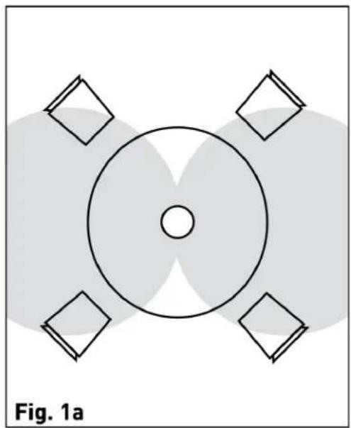

Single-Speaker "Left plus Right" Sound Distributed "Left plus Right" Sound


5.1 Surround Placement using Two H65-SM Speakers
6.1 Rear Placement using One H65-SM Speaker
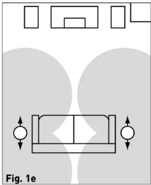
7.1 Surround + Rear Placement using Two H65-SM Speakers

7.1 Rear Placement using One H65-SM Speaker
Guided Soundfield™ Model


Front Left and Right Speakers Front Left, Center, Right Speakers


5.1 Surround Placement, diffuse soundfield 6.1 Rear Placement, diffuse soundfield

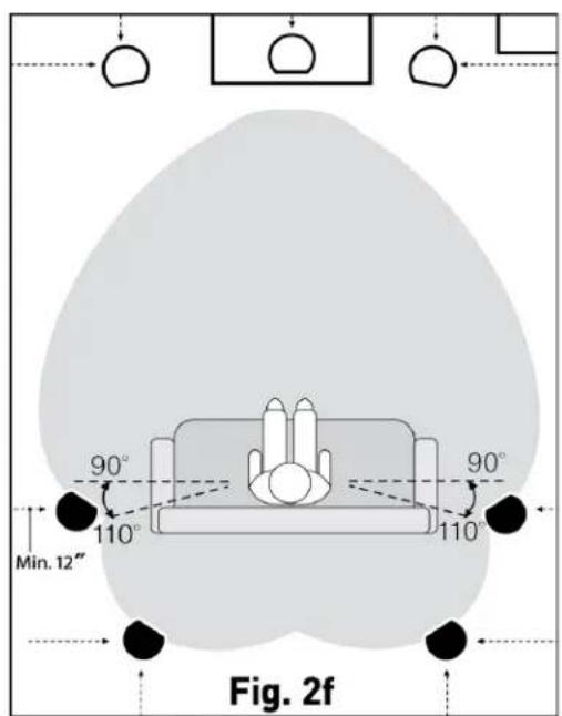
7.1 Rear Placement, diffuse soundfield Direct-Radiating Speakers in a 7.1 placement
10.0 Speaker Installation and Connection (pictorial)
SPEAKER INSTALLATION AND CONNECTION (pictorial)
NOTE: If the clamps are not set to the right position, use a screwdriver to turn the screws counter-clockwise until the clamps are in the correct position.
In-Ceiling Mounting


Fig. 3a Fig. 3b


Fig. 3c Fig. 3d
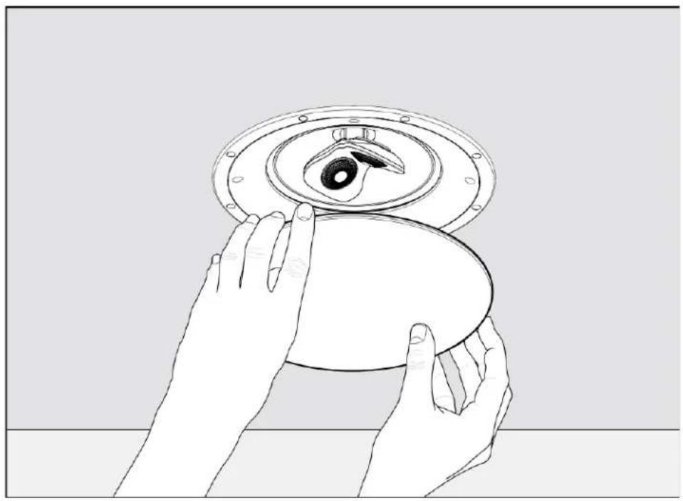
Fig. 3e
In-Wall Mounting


Fig. 4a Fig. 4b
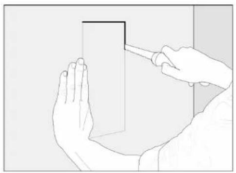
Fig. 4c Fig. 4d
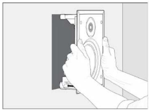


Fig. 4e Fig. 4f
11.0 Speaker Connection

Fig. 5a
Wiring for all models
except H65-SM, see below.

Fig. 5b
Two Speakers

Fig. 5c
One Speaker
12.0 Troubleshooting Guide
PROBLEM SOLUTION
| No Sound | Make sure receiver, preamp or amplifier is plugged in and turned on. Check power outlet at the wall is working. Are headphones plugged in, or is system on Mute? Re-check all connections. |
| No Sound from One or More Speakers | Check your balance control. Check that all power cords are properly plugged in and functioning. Swap the Left speaker cable with the Right speaker cable at the receiver/amplifier end to determine if the problem is with the speaker or something else (i.e. wiring, amplifier). |
| Lack of Bass or Dislocated Image (Stereo) | One or more speakers may be connected out of phase (their polarity is reversed). Re-check to ensure that each speaker’s cable is connected with correct polarity: red (+) to red (+) and black (-) to black (-). |
LIMITED WARRANTY
Paradigm® In-Wall/In-Ceiling CI Pro and Elite Series Speakers are warranted to be and remain free of manufacturing and/or material defects for a period of five (5) years from the date of original purchase. Within the time period specified, repair, replacement or adjustment of parts for manufacturing and/or material defects will be free of charge to the original owner.
Thermal or mechanical abuse/misuse is not covered under warranty.
Limitations:
* Warranty begins on date of original retail purchase from an Authorized Paradigm® Dealer only. It is not transferable;
- Warranty applies to product in normal residential use only. If product is subjected to any of the conditions outlined in the next section, warranty is void;
- Warranty does not apply if the product is used in professional or commercial applications;
Warranty is Void if:
• The product has been abused (intentionally or accidentally);
- The product has been used in conjunction with unsuitable or faulty equipment;
- The product has been subjected to damaging signals, derangement in transport, mechanical damage or any abnormal conditions;
- The product (including cabinet) has been tampered with or damaged by an unauthorized service facility;
- The serial number has been removed or defaced.
Owner Responsibilities:
- Provide normal/reasonable operating care and maintenance;
- Provide or pay for transportation charges for product to service facility;
- Provide proof of purchase (your sales receipt given at time of purchase from your Authorized Paradigm® Dealer must be retained for proof-of-purchase date).
Should servicing be required, contact your nearest Authorized Paradigm® Dealer, Paradigm Electronics Inc. or Import Distributor (outside the U.S. and Canada) to arrange, bring in or ship prepaid, any defective unit. Visit our website, www.paradigm.com for more information.
Paradigm Electronics Inc. reserves the right to improve the design of any product without assuming any obligation to modify any product previously manufactured.
This warranty is in lieu of all other warranties expressed or implied, of merchantability, fitness for any particular purpose and may not be extended or enlarged by anyone. In no event shall Paradigm Electronics Inc., their agents or representatives be responsible for any incidental or consequential damages. Some jurisdictions do not allow limitation of incidental or consequential damages, so this exclusion may not apply to you.
Retain manual and sales receipt for proof of warranty term and proof of purchase.
NOTES

- PARADIGM®
- CI
- HOME
- SERIES
- TABLE OF CONTENTS
- 1.0 FIREPROOF BACKBOXES
- FIREPROOF BACKBOXES
- BACKBOX FEATURES
- 2.0 YOUR NEW SPEAKERS
- YOUR NEW SPEAKERS
- 3.0 HOW TO AVOID SPEAKER DAMAGE
- HOW TO AVOID SPEAKER DAMAGE
- 4.0 YOUR LISTENING ROOM
- YOUR LISTENING ROOM
- 5.0 SPEAKER ASSEMBLY PARTS LIST
- SPEAKER ASSEMBLY PARTS LIST (ONE SPEAKER)
- 6.0 SPEAKER PLACEMENT GUIDELINES
- SPEAKER PLACEMENT GUIDELINES (ALL MODELS)
- LOCATION
- ACCURATE TIMBRE AND IMAGING
- BASS PERFORMANCE
- PLACEMENT OPTIONS FOR H65-SM SPEAKERS
- SINGLE SPEAKER, WIDE DISPERSION "LEFT PLUS RIGHT" CHANNEL SOUND (FIG. 1A)
- MULTIPLE SPEAKERS, DISTRIBUTED "LEFT PLUS RIGHT" CHANNEL SOUND (FIG. 1B)
- 5.1 SURROUND PLACEMENT USING TWO SPEAKERS (FIG. 1C)
- 6.1 REAR PLACEMENT USING ONE SPEAKER (FIG. 1D)
- 7.1 SURROUND + REAR PLACEMENT USING TWO SPEAKERS (FIG. 1E)
- 7.1 REAR PLACEMENT USING ONE SPEAKER (FIG. 1F)
- PLACEMENT OPTIONS FOR H65-A SPEAKERS WITH GUIDED SOUNDFIELD™
- GUIDED SOUNDFIELD™ LEFT/RIGHT SPEAKERS (FIG. 2A)
- ADDING A GUIDED SOUNDFIELD™ CENTER SPEAKER (FIG. 2B)
- GUIDED SOUNDFIELD™ SURROUNDS/REARS
- 5.1 SURROUND PLACEMENT (FIG. 2C)
- 6.1 REAR PLACEMENT (FIG. 2D)
- 7.1 SURROUND/REAR PLACEMENT (FIG. 2E)
- GUIDED SOUNDFIELD™ FOR DIRECT-RADIATING SURROUNDS/REARS (FIG. 2F)
- FINE TUNING THE GUIDED SOUNDFIELD™
- 7.0 COLOR-MATCH PAINTING
- COLOR-MATCH PAINTING (OPTIONAL)
- 8.0 INSTALLATION
- CONNECTING H65-SM SPEAKERS
- INSTALLING THE SPEAKER
- INSTALLING THE GRILLE
- 9.0 SPEAKER PLACEMENT (PICTORIAL)
- SPEAKER PLACEMENT (PICTORIAL)
- H65-SM SPEAKERS (ARROWS INDICATE DIRECTION OF TWEETERS)
- GUIDED SOUNDFIELD™ MODEL
- 10.0 SPEAKER INSTALLATION AND CONNECTION (PICTORIAL)
- SPEAKER INSTALLATION AND CONNECTION (PICTORIAL)
- 11.0 SPEAKER CONNECTION
- 12.0 TROUBLESHOOTING GUIDE
- LIMITED WARRANTY
- LIMITATIONS
- WARRANTY IS VOID IF
- OWNER RESPONSIBILITIES
Brand : Paradigm
Model : CI Home H55-R v2
Category : Loudspeaker