
CSD1X2U-V2 - Loudspeaker Bogen - Free user manual and instructions
Find the device manual for free CSD1X2U-V2 Bogen in PDF.


| Product Type | Ceiling Speaker System |
| Driver Size | 8" (203 mm) |
| Power Taps (70V) | 14 W, 4 W |
| Power Taps (25V) | 14 W, 4 W |
| 8Ω Operation | 10 W maximum |
| Transformer Bypass | Yes (Blue wire for 8Ω) |
| Compatible Nyquist Modules | NQ-GA10P, NQ-GA10PV, NQ-GA20P2, NQ-GA40P3, NQ-GAXMR1 |
| PoE Support | Yes, via Nyquist modules (PoE, PoE+, PoE++) |
| VoIP Intercom Function | Yes (with NQ-GA10P/V) |
| Mounting Plate | V2 unique plate for Nyquist integration |
| Ceiling Tile Fit | 2×2 ft (11½" cutout) or 2×4 ft (35½" cutout) |
| Seismic Tether | Included |
| Wire Leads Color Code | Red (70V), Yellow (25V), Blue (8Ω), White (tap select), Black (COM) |
| Safety Listing | UL 62368 |
| Warranty | 2 years |
| Wiring Compliance | NFPA 70 |
| Maximum Additional Speakers (25V/70V) | Depends on amplifier load, daisy-chain allowed |
| Installation Hardware Included | Tile support rail, mounting plate, electrical box cover |
| Date of Manual | 4/2023 |
Frequently Asked Questions - CSD1X2U-V2 Bogen
User questions about CSD1X2U-V2 Bogen
0 question about this device. Answer the ones you know or ask your own.
Ask a new question about this device
Download the instructions for your Loudspeaker in PDF format for free! Find your manual CSD1X2U-V2 - Bogen and take your electronic device back in hand. On this page are published all the documents necessary for the use of your device. CSD1X2U-V2 by Bogen.
USER MANUAL CSD1X2U-V2 Bogen
natural_image
3D rendering of a black industrial fan or enclosure component with mounting base and control panel (no visible text or symbols)CSD1X2U-V2
70V, 25V, and 8Ω Speaker System
Installation and Use Guide
The CSD1X2U-V2 ceiling has an 8" driver and a tap selector that allows it to be run as a 14 W to 4W speaker at 25V or 70V. It also includes a wire that bypasses the transformer and allows the speaker to operate at 8Ω. The V2 version of the speaker includes a unique mounting plate to greatly expand its capabilities by allowing several of Bogen's Nyquist products to be mounted to the speaker.
Mounting Plate
The mounting plate allows for the addition of several of Bogen's Nyquist products, including the NQ-GA10P, NQ-GA10PV, NQ-GA20P2, NQ-GA40P3, and the NQ-GAXMR1. Through this product integration, the CSD1X2U-V2 can operate as a Nyquist PoE enabled active loudspeaker system as well as a VoIP intercom station.
Passive Speaker Configuration
Electrical Connection
- Remove electrical box cover, install cable clamp (if desired), and feed interconnecting cable into the electrical box (see Figure 1).
- See table on the right to select correct wire types.
- Cut bare wire tip off of unused speaker leads. Secure all mechanical connections and reinstall the electrical box cover.
- Set tap selector switch to proper tap setting.
Note: All wiring must comply with NFPA 70.

| COLOR LEAD | |
| RED 70V | |
| YELLOW 25V | |
| BLUE 8Ω | |
| WHITE Connect to BLUE for 70V and 25V; disconnect for 8Ω Input | |
| BLACK COM | |

Figure 1: Electrical connections.
Nyquist PoE Amplifier and Speaker Configuration
Necessary components: NQ-GA10P or NQ-GA10PV.
Figure 2 shows the positioning for the mounting of the VoIP Intercom Module (NQ-GA10P) onto the speaker's mounting plate. For a closer look at the mounting plate, refer to Figure 3.

Figure 2: Mounting Intercom Module (NQ-GA10P shown)
CSDV2 Mounting Plate
The placement of mounting holes varies per module (see Figure 3). They are as follows:
$$ A = N Q - G A X M R 1 $$
$$ B = N Q - G A 4 0 P 3 $$
$$ C = N Q - G A 1 0 P, N Q - G A 1 0 P V, o r N Q - G A 2 0 P 2 $$

Figure 3: Mounting plate with holes marked for specific modules.
Wiring Instructions
Run, at minimum, a Cat 5 cable from the appropriate-sized PoE switch to the VoIP module. Wire the output of the VoIP module to the CSD speaker in the 8Ω configuration (see Figure 4). This has a 10W maximum at 8Ω operation.

Figure 4: NQ-GA10P VoIP Intercom Module connect to CSD speaker.
Nyquist PoE Amplifier and 25V/70V Speaker Configuration
Necessary Components: NQ-GA10P, NQ-GA10PV, NQ-GA20P2, or NQ-GA40P3, and NQ-GAXMR1.
Figure 5 shows the positioning for the mounting of both the VoIP Intercom Module (NQ-GA10P) and the Distributed Audio Transformer (NQ-GAXMR1) onto the speaker's mounting plate. Refer back to Figure 3 for the placement of the mounting holes used for these two modules.
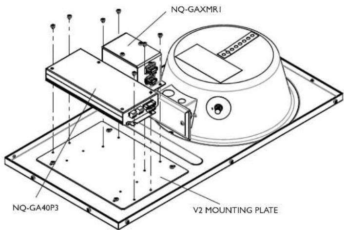
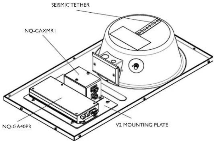
Figure 5: Mounting Intercom Module (NQ-GA40P3 shown) and NQ-GAXMR1
Wiring Instructions
Run, at minimum, a Cat 5 cable from the appropriate-sized PoE switch and connect this to the PoE amplifier module.
Figure 6 shows the NQ-GA40P3 connected to the NQ-GAXMR1. The NQ-GA40P3 can be replaced by either the NQ-GA10P/V (see Figure 7) or NQ-GA20P2 (see Figure 8) modules. These illustrations also show 25V wiring running from NQ-GAXMR1 to a CSD1X2U-V2 speaker and additional speakers if needed. 70V is also an option, but both outputs cannot be used simultaneously. If additional speakers are needed, proper care should be taken when wiring so the amplifier does not become overloaded.

Figure 6: NQ-GA40P3 PoE++ Amplifier Module connected to NQ-GAXMRI Audio Transformer, CSD1X2U-V2 Speaker, and additional speakers.
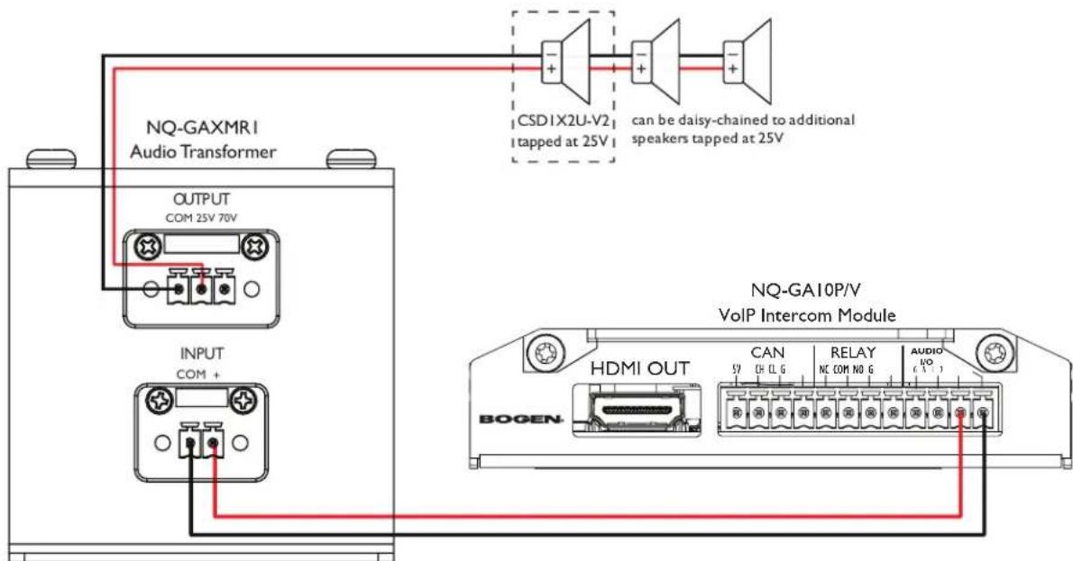
Figure 7: NQ-GA10P/V VoIP Intercom Module connected to NQ-GAXMR1 Audio Transformer then to speaker.
Note: The NQ-GA10P/V intercom function cannot be used when the speaker output is wired in the configuration illustrated in Figure 7.
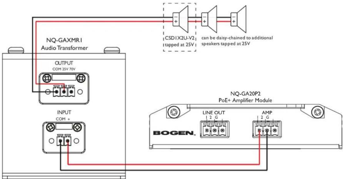
Figure 8: NQ-GA20P2 PoE+ Amplifier Module connected to NQ-GAXMR1 Audio Transformer and speaker.
Ceiling Mounting Instructions
- For 2 × 2 ft. tile space, cut ceiling tile to 11½". For 2 × 4 ft. tile space, cut ceiling tile to 35½".
- Place speaker in ceiling opening.
- Slide Tile Support Rail under speaker edge beside the opening.
- Drop in the ceiling tile.

Figure 9: Speaker installation with mounting plate and tile support rail.
Safety
Listed to UL62368.
Two-Year Warranty
The CSD1X2U-V2 is warranted to be free from defects in material or workmanship for two (2) years from the date of sale to the original purchaser. This warranty does not extend to any of our products that have been subjected to abuse, misuse, improper storage, neglect, accident, improper installation or have been modified or repaired or altered in any manner whatsoever, or where the serial number or date code has been removed or defaced.
4/2023
Brand : Bogen
Model : CSD1X2U-V2
Category : Loudspeaker