
DWS-3026 - Network switch D-LINK - Free user manual and instructions
Find the device manual for free DWS-3026 D-LINK in PDF.


| Product Type | Managed Layer 2/3 Gigabit Ethernet Switch with Wireless LAN Controller |
| Model | D-Link DWS-3026 |
| Ports | 24 x 10/100/1000 Mbps Gigabit Ethernet ports (with PoE), 4 x Combo SFP ports, 2 x 10GE slots for optional modules (DEM-410X or DEM-410CX) |
| Managed Access Points | Up to 48 D-Link Access Points (DWL-3500AP, DWL-8500AP, DWL-8600AP) |
| Wireless Clients | Up to 8000 clients total, up to 512 per AP (256 per radio) |
| Dimensions (W x D x H) | Standard 19-inch rackmount, approximately 440 x 260 x 44 mm (17.3 x 10.2 x 1.7 in) |
| Weight | Approximately 3.0 kg (6.6 lbs) |
| Power Supply | AC 100-240 V, 50-60 Hz, internal; optional external Redundant Power Supply (RPS) |
| Power Over Ethernet (PoE) | IEEE 802.3af PoE on all 24 Gigabit ports |
| Switching Capacity | Up to 88 Gbps (non-blocking) |
| Forwarding Rate | Up to 65.5 Mpps |
| MAC Address Table | 16K entries |
| VLAN Support | IEEE 802.1Q, up to 4096 VLANs |
| Layer 3 Features | Static and dynamic routing (RIP), IP tunneling for L3 roaming, DHCP server/relay |
| Wireless Standards | IEEE 802.11a/b/g/n, supports 2.4 GHz and 5 GHz bands |
| Security | WEP, WPA/WPA2 (Personal/Enterprise), 802.1X, MAC authentication, rogue AP detection |
| Management Interfaces | Web GUI (HTTP/HTTPS), CLI (Telnet/SSH/Serial), SNMP v1/v2c/v3 |
| Cooling | Internal fans with side ventilation; ensure 6 inches clearance |
| Operating Temperature | 0°C to 40°C (32°F to 104°F) |
| Safety & Emissions | FCC Class A, CE Mark, UL, cUL |
| Package Contents | Switch, AC power cord, mounting kit, rubber feet, RS-232 console cable, CD with manual |
| Warranty | 1 year limited hardware warranty (USA); varies by region |
Frequently Asked Questions - DWS-3026 D-LINK
reset config from Privileged EXEC mode.User questions about DWS-3026 D-LINK
0 question about this device. Answer the ones you know or ask your own.
Ask a new question about this device
Download the instructions for your Network switch in PDF format for free! Find your manual DWS-3026 - D-LINK and take your electronic device back in hand. On this page are published all the documents necessary for the use of your device. DWS-3026 by D-LINK.
USER MANUAL DWS-3026 D-LINK
natural_image
Illustration of a network equipment unit with multiple ports and connectors (no visible text or symbols)USER MANUAL
PRODUCT MODEL: DWS-3000 SERIES
DWL-3500AP/8500AP/8600AP
UNIFIED WIRED & WIRELESS ACCESS SYSTEM
RELEASE 3.0
DECEMBER 2010
FCC Warning
This equipment has been tested and found to comply with the limits for a Class A digital device, pursuant to Part 15 of the FCC Rules. These limits are designed to provide reasonable protection against harmful interference when the equipment is operated in a commercial environment. This equipment generates, uses, and can radiate radio frequency energy and, if not installed and used in accordance with this manual, may cause harmful interference to radio communications. Operation of this equipment in a residential area is likely to cause harmful interference in which case the user will be required to correct the interference at his own expense.
CE Mark Warning
This is a Class A product. In a domestic environment, this product may cause radio interference in which case the user may be required to take adequate measures.
Warnung!
Section 1: About This Document....17
Audience....17
Organization 17
Document Conventions....17
Safety Instructions....18
Safety Cautions....18
General Precautions for Rack-Mountable Products....19
Protecting Against Electrostatic Discharge....20
Battery Handling Reminder 20
Section 2: Overview of the D-Link Unified Access System....21
D-Link Unified Access System Components....21
D-Link Unified Switch 21
D-Link Access Point....22
WLAN Visualization 22
D-Link Unified Access System Topology 23
Single Unified Switch Deployment 24
Peer Unified Switch Deployment 24
Understanding the User Interfaces 25
Using the Web Interface....25
Using the Command-Line Interface....28
Using SNMP 29
Wireless System Features and Standards Support....29
Section 3: Planning the D-Link Unified Access System Network....33
System Requirements.... 33
WLAN Topology Considerations 34
Access Point-to-Switch Discovery....36
Access Point Placement....36
Network Planning to Support Layer 3 Roaming 37
Section 4: Installing the Hardware ....39
Hardware Overview....39
Front Panel Components....39
LED Indicators 40
Rear Panel Description 42
Side Panels 43
Installation 43
Package Contents....43
Installation Guidelines ....43
Installing the Switch without the Rack....44
Installing the Switch in a Rack....44
Powering On the Switch....45
Installing the SFP ports 45
Installing the Optional Modules....46
Connecting to the External Redundant Power System....48
Connecting the Switch 48
Connecting the Switch to the Network....49
Connecting the Switch and AP Directly....49
Connecting the Switch and AP through the L2/L3 Network 49
Connecting to the Core Network....50
Section 5: Installing the D-Link Unified Access System .... 51
System Deployment Overview....51
Connecting the Switch to the Network....52
Null User Authentication ....53
Enabling the WLAN Features on the Switch....53
Preparing the Access Points....55
Logging on to the AP 55
Changing the AP Password ....56
Configuring 802.1X Authentication Information on the AP....56
Configuring AP-to-Switch Authentication Information....57
Configuring VLAN Information on the Access Point ....57
Discovering Access Points and Peer Switches....58
Understanding the Discovery Methods ....58
Discovery and Peer Switches 61
Assigning the IP Address to Switches and Managed APs....61
Enabling the AP and Peer Switch Discovery....64
Authenticating and Validating Access Points....70
Configuring AP Authentication ....71
Using the Local Database for AP Validation....72
Using the RADIUS Database for AP Validation....73
Software User Manual D-Link Unified Access System
02/15/2011
Managing Failed or Rogue APs....74
Section 6: Configuring Access Point Settings ....77
AP Profiles, Networks, and the Local Database....77
Access Point Profiles....77
Networks 78
Local Access Point Database 78
Configuring AAA and RADIUS Settings....79
Configuring Wireless Radio Settings 81
Configuring SSID Settings....86
Managing Virtual Access Point Configuration 87
Wireless Network Configuration 88
Configuring the Default Network 88
Wireless Network Summary 92
Enabling and Configuring Additional VAPs....94
Configuring a VAP for L3 Tunnels 95
Configuring AP Security 97
Configuring Valid Access Point Settings....101
Section 7: Managing and Maintaining D-Link Access Points ....105
Resetting the Access Points....105
Managing Radio Frequency Settings....105
Configuring Channel Plan and Power Settings 106
Viewing the Channel Plan History 108
Initiating Manual Channel Plan Assignments....109
Initiating Manual Power Adjustments....110
Upgrading the Access Point Software 111
Performing Advanced Access Point Management....114
Enabling AP Debugging....115
Adjusting the Channel and Power 116
Section 8: Monitoring Status and Statistics ....119
Monitoring Wireless Global Information 119
Viewing IP Discovery Status 122
Monitoring Peer Switch Status....122
Monitoring All Access Points 124
Monitoring Managed Access Point Status....126
Monitoring Managed AP Statistics....133
134
Viewing Access Point Authentication Failure Status....137
Monitoring Rogue and RF Scan Access Points....138
Detailed Access Point RF Scan Status....140
Monitoring WIDS AP De-Authentication Attack Status 141
Monitoring Associated Client Information....142
Viewing Associated Client Status....143
Monitoring Associated Client QoS Information 143
Viewing Associated Client SSID Status 146
Viewing Associated Client VAP Status ....147
Viewing Associated Client Statistics....147
Viewing Client Authentication Failure Status....149
Monitoring and Managing Ad Hoc Clients....151
Section 9: Configuring Advanced Settings ....153
Creating, Configuring, and Managing AP Profiles....153
Creating, Copying, and Deleting AP Profiles ....154
Applying an AP Profile....156
Configuring Global Settings....157
Enabling SNMP Traps 158
Configuring QoS 160
Section 10: Configuring the Captive Portal ....165
Configuring Global Captive Portal Settings....166
Configuring the Captive Portal....167
Changing the Captive Portal Settings....168
Customizing the Captive Portal Web Page 170
Monitoring and Configuring Captive Portal Users....177
Configuring Users in the Local Database ....178
Configuring Users in a Remote RADIUS Server 179
Associating Interfaces with the Captive Portal....180
Viewing the Captive Portal Global Status....181
Viewing CP Activation and Activity Status ....182
Viewing Interface Activation Status ....184
Viewing Interface Capability Status....184
Viewing the Client Summary....185
Viewing Client Detail....186
Software User Manual D-Link Unified Access System
02/15/2011
Viewing the Client Statistics....187
Viewing the Client Interface Association Status....188
Viewing the Client CP Association Status....189
SNMP Trap Configuration 190
Section 11: Visualizing the Wireless Network....191
Importing and Configuring a Background Image 191
Setting Up the Graph Components 192
Creating a New Graph 192
Graphing the WLAN Components 195
Understanding the Menu Bar Options ....197
Legend Menu....198
Managing the Graph....201
Appendix A: D-Link Unified Access System Default Settings....203
Default D-Link Unified Switch Settings....203
Default D-Link Access Point Settings 204
Default D-Link Access Point Profile Settings....204
Default Captive Portal Settings....206
Appendix B: Configuring the External RADIUS Server....207
Configuring RADIUS Settings for Access Points 207
FreeRADIUS Server Configuration Example....208
Configuring RADIUS Clients 208
Creating and Including an Attribute Dictionary....208
Adding Access Points to the Valid AP Database 210
Configuring RADIUS Settings for Wireless Clients 210
Configuring RADIUS for Client MAC Authentication 210
FreeRADIUS Example for Wireless Client Configuration 211
Configuring User-Based Authentication and Dynamic VLANs.... 211
Configuring MAC Authentication 212
Appendix C: L3 Roaming Example ......213
Configuring the WLAN and Tunnel Interfaces 213
Using a Loopback Interface for the Wireless Functions 214
Creating the VLAN Routing Interface 215
Configuring the L3 Tunnel Network....218
Example of Configuring L3 Roaming by Using the CLI....218
Example of Configuring L3 Roaming by Using the Web Interface ....220
Configuring DHCP Relay and the DHCP Server....223
Configuring the Relay Agent ....223
Configuring the DHCP Server 224
Appendix D: Understanding Quality of Service....227
QoS and Load Balancing....227
802.11e and WMM Standards Support 227
Coordinating Traffic Flow 227
QoS Queues and DSCP on Packets 228
EDCF Control of Data Frames and AIFS 229
Random Backoff and Contention Windows....229
Packet Bursting for Better Performance....230
TXOP Interval for Client Stations....230
802.1p and DSCP tags 230
Appendix E: Limited Warranty (USA Only) 233
Product Registration 236
Limited Warranty 236
What You Must Do For Warranty Service:....237
What Is Not Covered....237
Trademarks 238
Copyright Statement....238
FCC Warning 238
Appendix F: Technical Support....239
International Offices 263
Registration Card
All Countries and Regions Excluding USA....264
LIST OF FIGURES
Figure 1: Sample WLAN Visualization....23
Figure 2: Single Unified Switch with Layer 2 Roaming Support.... 24
Figure 3: Peer Unified Switch with Layer 3 Roaming Support....25
Figure 4: Web Interface Layout....26
Figure 5: Cascading Navigation Menu....27
Figure 6: Hierarchical Tree Navigation Menu ....27
Figure 7: D-Link Unified Access System Components 34
Figure 8: Wiring Closet Topology....35
Figure 9: Data Center Topology....36
Figure 10: Inter-Subnet Roaming....38
Figure 11: Front Panel View of the DWS-3024L as Shipped....40
Figure 12: Front Panel View of the DWS-3024 as Shipped....40
Figure 13: Front Panel View of the DWS-3026 as Shipped....40
Figure 14: LED Indicators on DWS-3024L....41
Figure 15: LED Indicators on DWS-3024....41
Figure 16: LED Indicators on DWS-3026....41
Figure 17: Rear panel view of DWS-3024/DWS-3024L 43
Figure 18: Rear panel view of DWS-3026 43
Figure 19: Prepare Switch for Installation on a Desktop or Shelf 44
Figure 20: Fasten Mounting Brackets to Switch .... 44
Figure 21: Mounting the Switch in a Standard 19" Rack ....45
Figure 22: Inserting the Fiber-Optic Transceivers into the Switch 46
Figure 23: Front Panel of the DEM-410X....47
Figure 24: Front Panel of the DEM-410CX....47
Figure 25: Inserting the optional module into the Switch (DWS-3026) 47
Figure 26: DWS-3026 with optional DEM-410X module installed....48
Figure 27: RPS Connector....48
Figure 28: Switch and AP Connected Directly....49
Figure 29: Switch and APs Connected Through Network....50
Figure 30: Switch Connected to Network Core....50
Figure 31: Ethernet Connection for Static IP Assignment....56
Figure 32: L2 Discovery Example....59
Figure 33: L3 Discovery Example 1....59
Figure 34: L3 Discovery Example 2 ....60
Figure 35: DHCP Option Example ......60
Figure 36: Requiring AP Authentication ....71
Figure 37: MAC Access Control 80
Figure 38: Radio Settings....82
Figure 39: VAP Settings 86
Figure 40: Configuring Network Settings....88
Figure 41: AP Profile With VAP Enabled....94
Figure 42: Networks Available to the Wireless Client....95
Figure 43: L3 Roaming Example....96
Figure 44: AP Network Security Options....97
Figure 45: Static WEP Configuration....98
Figure 46: WPA Personal Configuration ....100
Figure 47: Adding a Valid AP 102
Figure 48: Configuring a Valid AP ....103
Figure 49: Access Point Reset 105
Figure 50: RF Channel Plan and Power Configuration 107
Figure 51: Channel Plan History ....108
Figure 52: Manual Channel Plan....109
Figure 53: Manual Power Adjustments ...... 110
Figure 54: AP Upgrade....112
Figure 55: AP Upgrade Status. 113
Figure 56: Advanced AP Management 114
Figure 57: Global WLAN Status ....120
Figure 58: Wireless Discovery Status ....122
Figure 59: Peer Switch Status....123
Figure 60: All Access Points....124
Figure 61: Managed AP Status .... 126
Figure 62: Managed AP Statistics....133
Figure 63: Authentication Failed AP Status....137
Figure 64: RF Scan ....139
Figure 65: AP De-Authentication Attack Status ....142
Figure 66: Associated Client Status ....142
Figure 67: Associated Client QoS Status....144
Figure 68: Client Authentication Failure Status .... 150
Software User Manual D-Link Unified Access System
02/15/2011
Figure 69: Ad Hoc Clients 151
Figure 70: Multiple AP Profiles....153
Figure 71: Adding a Profile .... 154
Figure 72: Configuring an AP Profile 155
Figure 73: Applying the AP Profile....156
Figure 74: Global Configuration....157
Figure 75: SNMP Trap Configuration....158
Figure 76: QoS Configuration 160
Figure 77: Navigating to the Captive Portal Feature.... 165
Figure 78: Global Captive Portal Configuration .... 166
Figure 79: Captive Portal Summary....167
Figure 80: Captive Portal Configuration....168
Figure 81: CP Web Page Customization - Global Parameters.... 171
Figure 82: CP Web Page Customization - Authentication Page....173
Figure 83: CP Web Page Customization - Welcome Page.... 175
Figure 84: CP Web Page Customization - Logout Page.... 175
Figure 85: CP Web Page Customization - Logout Success Page 176
Figure 86: Captive Portal Local User Summary....177
Figure 87: Local User Configuration .... 178
Figure 88: Global Captive Portal Configuration .... 180
Figure 89: Global Captive Portal Status.... 182
Figure 90: CP Activation and Activity Status.... 183
Figure 91: Interface Activation Status.... 184
Figure 92: Interface Capability Status.... 185
Figure 93: Client Summary ...... 186
Figure 94: Client Detail 187
Figure 95: Client Statistics .... 188
Figure 96: Interface - Client Status 188
Figure 97: CP - Client Status 189
Figure 98: SNMP Trap Configuration....190
Figure 99: Sample WLAN Visualization....191
Figure 100: Multiple Graphs ...... 194
Figure 101:List View and Tabbed View .... 195
Figure 102: Component Tool Tip.... 196
Figure 103: Graphed Components ...... 196
D-Link Unified Access System Software User Manual
02/15/2011
Figure 104:Legend....199
Figure 105:Sentry Mode - Detailed View .... 199
Figure 106:Channel Colors ....200
Figure 107: Tool Tip for Radio Managed AP Information ....200
Figure 108: Wireless Component Attributes ....201
Figure 109:Example of a Network with L3 Tunnel Subnet....213
Figure 110: Traffic Prioritization ....231
LIST OF TABLES
Table 1: Typographical Conventions ...... 18
Table 2: D-Link Access Points.... 22
Table 3: LED Description....41
Table 4: Basic Wireless Global Configuration .... 54
Table 5: IEEE 802.1X Supplicant Commands .... 57
Table 6: AP VLAN Commands .... 58
Table 8: L3/IP Discovery....66
Table 9: Global RADIUS Server 79
Table 10: MAC Authentication....80
Table 11: Radio Settings 82
Table 12: Advanced Radio Configuration....85
Table 13: Default VAP Configuration....87
Table 14: Wireless Network Configuration ...... 89
Table 15: Wireless Network Summary ...... 92
Table 16: Static WEP....98
Table 17: Static WPA.... 100
Table 18: Valid Access Point Summary.... 102
Table 19: Valid AP Configuration.... 103
Table 20: RF Channel Plan and Power Adjustment .... 107
Table 21: Channel Plan History.... 109
Table 22: AP Upgrade 112
Table 23: AP Upgrade Status.... 113
Table 24: Advanced AP Management....115
Table 25: AP Debug 115
Table 26: Managed AP Channel/Power Adjust 116
Table 27: Global WLAN Statistics.... 120
Table 28: Peer Switch Status ...... 123
Table 29: Monitoring All Access Points ...... 125
Table 30: Managed Access Point Status.... 126
Table 31: Detailed Managed Access Point Status.... 128
Table 32: Managed AP Radio Summary ...... 129
Table 33: Managed AP Radio Detail 130
Table 34: Managed AP Neighbor Status .... 131
Table 35: Neighbor AP Clients....132
Table 36: Managed Access Point VAP Status....133
Table 37: Managed Access Point WLAN Summary Statistics ....134
Table 38: Managed Access Point Ethernet Summary Statistics....134
Table 39: Detailed Managed Access Point Statistics....135
Table 40: Managed Access Point Radio Statistics....135
Table 41: Managed Access Point VAP Statistics....136
Table 42: Access Point Authentication Failure Status ....138
Table 43: Access Point RF Scan Status .... 140
Table 44: AP De-Authentication Attack Status....142
Table 45: Associated Client Status Summary....143
Table 46: Associated Client QoS Status....144
Table 47: Detailed Associated Client Status .... 145
Table 48: Associated Client Neighbor AP Status....146
Table 49: Associated Client SSID Status....147
Table 50: Associated Client VAP Status....147
Table 51: Associated Client Association Summary Statistics....147
Table 52: Associated Client Summary Statistics....148
Table 53: Associated Client Association Detail Statistics ...... 148
Table 54: Associated Client Session Detail Statistics....149
Table 55: Failed Client Status....150
Table 56: Client Authentication Failure Status....151
Table 57: Ad Hoc Client Status 152
Table 58: General Global Configurations....157
Table 59: SNMP Traps ......159
Table 60: QoS Settings....161
Table 61: Global Captive Portal Configuration....166
Table 62: Captive Portal Summary ...... 167
Table 63: CP Configuration....168
Table 64: CP Web Page Customization - Global Parameters ......172
Table 65: CP Web Page Customization - Authentication Page ......173
Table 66: CP Web Page Customization - Welcome Page 175
Table 67: CP Web Page Customization - Logout Page 176
Table 68: CP Web Page Customization - Logout Success Page 176
Table 69: Local User Summary....177
Software User Manual D-Link Unified Access System
02/15/2011
Table 70: Local User Configuration ...... 178
Table 71: Captive Portal User RADIUS Attributes.... 179
Table 72: Global Captive Portal Configuration .... 181
Table 73: Global Captive Portal Status....182
Table 74: CP Activation and Activity Status....183
Table 75: Interface Activation Status....184
Table 76: Interface and Capability Status....185
Table 77: Client Summary 186
Table 78: Client Detail 187
Table 79: Client Interface Association Connection Statistics.... 188
Table 80: Interface - Client Status .... 189
Table 81: CP - Client Status .... 189
Table 82: SNMP Trap Configuration.... 190
Table 83: WLAN Visualization Menu Bar Options 197
Table 84: Component Information....201
Table 85: Switch Defaults....203
Table 86: Default AP Settings....204
Table 87: AP Profile Default Settings 204
Table 88: Default Captive Portal Settings....206
Table 89: RADIUS Attributes for the Access Point....207
Table 90: RADIUS Attributes for Wireless Clients 210
Table 91: RADIUS Attributes for Wireless Client MAC Authentication....211
Table 92: L3 Tunnel Status Values.... 220
Table 93: VLAN Priority Tags 231
Section 1: About This Document
This guide describes the planning, setup, configuration, administration, and maintenance for the D-Link Unified Access System.
AUDIENCE
The information in this guide is intended for the person responsible for installing, configuring, monitoring, and maintaining the D-Link Unified Access System as part of a network infrastructure.
ORGANIZATION
The D-Link Unified Access System User Manual contains the following chapters:
- Section 2: "Overview of the D-Link Unified Access System" on page 21
- Section 3: "Planning the D-Link Unified Access System Network" on page 33
• Section 4: "Installing the Hardware" on page 39 - Section 5: "Installing the D-Link Unified Access System" on page 51
• Section 6: "Configuring Access Point Settings" on page 77
• Section 7: "Managing and Maintaining D-Link Access Points"
• Section 8: “Monitoring Status and Statistics” on page 119
• Section 9: "Configuring Advanced Settings"
• Section 10: "Configuring the Captive Portal" on page 165
• Section 11: "Visualizing the Wireless Network" on page 191 - Appendix A: "D-Link Unified Access System Default Settings" on page 203
- Appendix B: "Configuring the External RADIUS Server" on page 207
- Appendix C: "L3 Roaming Example" on page 213
- Appendix D: "Understanding Quality of Service" on page 227
- Appendix E: "Limited Warranty (USA Only)" on page 233
- Appendix F: "Technical Support" on page 239
DOCUMENT CONVENTIONS
This section describes the conventions this document uses.

Note: A Note provides more information about a feature or technology.

Caution! A Caution provides information about critical aspects of the configuration, combinations of settings, events, or procedures that can adversely affect network connectivity, security, and so on.
This guide uses the typographical conventions that Table 1 on page 18 describes.
Table 1: Typographical Conventions
| Symbol Description Example | ||
| Bold | Menu titles, page names, and button names | Click Submit to apply your settings. |
| Blue Text | Hyperlinked text. | See “About This Document” on page 17. |
| courier font Screen text, file names. (switch-prompt) # | ||
| courier bold | Commands, user-typed command-line entries | show network |
| courier font italics | Command parameter, which might be a variable or fixed value. | value |
| <> Angle brackets | Indicates a parameter is a variable. You must enter a value in place of the brackets and text inside them. | |
| [] Square brackets | Indicates an optional fixed parameter. | [value] |
| [<>] Angle brackets within square brackets | Indicates an optional variable. | [] |
| {} curly braces | Indicates that you must select a parameter from the list of choices. | {choice1 | choice2} |
| | Vertical bars | Separates the mutually exclusive choices. | choice1 | choice2 |
| [{}] Braces within square brackets | Indicate a choice within an optional element. | [{choice1 | choice2}] |
SAFETY INSTRUCTIONS
Use the following safety guidelines to ensure your own personal safety and to help protect your system from potential damage.
Safety Cautions
To reduce the risk of bodily injury, electrical shock, fire, and damage to the equipment, observe the following precautions.
- Observe and follow service markings. Do not service any product except as explained in your system documentation. Opening or removing covers that are marked with the triangular symbol with a lightning bolt may expose you to electrical shock. Only a trained service technician should service components inside these compartments.
-
If any of the following conditions occur, unplug the product from the electrical outlet and replace the part or contact your trained service provider:
-
The power cable, extension cable, or plug is damaged.
- An object has fallen into the product.
- The product has been exposed to water.
- The product has been dropped or damaged.
-
The product does not operate correctly when you follow the operating instructions.
-
Keep your system away from radiators and heat sources. Also, do not block the cooling vents.
- Do not spill food or liquids on your system components, and never operate the product in a wet environment. If the system gets wet, see the appropriate section in your troubleshooting guide or contact your trained service provider.
- Do not push any objects into the openings of your system. Doing so can cause a fire or an electric shock by shorting out interior components.
- Use the product only with approved equipment.
-
Allow the product to cool before removing covers or touching internal components.
-
Operate the product only from the type of external power source indicated on the electrical ratings label. If you are not sure of the type of power source required, consult your service provider or local power company.
- To help avoid damaging your system, be sure the voltage selection Switch (if provided) on the power supply is set to match the power available at your location:
- 115 volts (V)/60 hertz (Hz) in most of North and South America and some Far Eastern countries such as South Korea and Taiwan
- 100 V/50 Hz in eastern Japan and 100 V/60 Hz in western Japan
- 230 V/50 Hz in most of Europe, the Middle East, and the Far East
• Also be sure that attached devices are electrically rated to operate with the power available in your location.
- Use only approved power cable(s). If you have not been provided with a power cable for your system or for any AC-powered option intended for your system, purchase a power cable that is approved for use in your country. The power cable must be rated for the product and for the voltage and current marked on the product's electrical ratings label. The voltage and current rating of the cable should be greater than the ratings marked on the product.
- To help prevent an electric shock, plug the system and peripheral power cables into properly grounded electrical outlets. These cables are equipped with three-prong plugs to help ensure proper grounding. Do not use adapter plugs or remove the grounding prong from a cable. If you must use an extension cable, use a 3-wire cable with properly grounded plugs.
- Observe extension cable and power strip ratings. Make sure that the total ampere rating of all products plugged into the extension cable or power strip does not exceed 80 percent of the ampere ratings limit for the extension cable or power strip.
- To help protect your system from sudden, transient increases and decreases in electrical power, use a surge suppressor, line conditioner, or uninterruptible power supply (UPS).
- Position system cables and power cables carefully; route cables so that they cannot be stepped on or tripped over. Be sure that nothing rests on any cables.
- Do not modify power cables or plugs. Consult a licensed electrician or your power company for site modifications. Always follow your local/national wiring rules.
- When connecting or disconnecting power to hot-pluggable power supplies, if offered with your system, observe the following guidelines:
- Install the power supply before connecting the power cable to the power supply.
- Unplug the power cable before removing the power supply.
- If the system has multiple sources of power, disconnect power from the system by unplugging all power cables from the power supplies.
- Move products with care; ensure that all casters and/or stabilizers are firmly connected to the system. Avoid sudden stops and uneven surfaces.
General Precautions for Rack-Mountable Products
Observe the following precautions for rack stability and safety. Also refer to the rack installation documentation accompanying the system and the rack for specific caution statements and procedures.
- Systems are considered to be components in a rack. Thus, “component” refers to any system as well as to various peripherals or supporting hardware.

Caution! Installing systems in a rack without the front and side stabilizers installed could cause the rack to tip over, potentially resulting in bodily injury under certain circumstances. Therefore, always install the stabilizers before installing components in the rack.
- After installing system/components in a rack, never pull more than one component out of the rack on its slide assemblies at one time. The weight of more than one extended component could cause the rack to tip over and may result in serious injury.
- Before working on the rack, make sure that the stabilizers are secured to the rack, extended to the floor, and that the full
weight of the rack rests on the floor. Install front and side stabilizers on a single rack or front stabilizers for joined multiple racks before working on the rack.
• Always load the rack from the bottom up, and load the heaviest item in the rack first.
• Make sure that the rack is level and stable before extending a component from the rack.
- Use caution when pressing the component rail release latches and sliding a component into or out of a rack; the slide rails can pinch your fingers.
- After a component is inserted into the rack, carefully extend the rail into a locking position, and then slide the component into the rack.
- Do not overload the AC supply branch circuit that provides power to the rack. The total rack load should not exceed 80 percent of the branch circuit rating.
- Ensure that proper airflow is provided to components in the rack.
- Do not step on or stand on any component when servicing other components in a rack.

Note: A qualified electrician must perform all connections to DC power and to safety grounds. All electrical wiring must comply with applicable local or national codes and practices.

Caution! Never defeat the ground conductor or operate the equipment in the absence of a suitably installed ground conductor. Contact the appropriate electrical inspection authority or an electrician if you are uncertain that suitable grounding is available.

Caution! The system chassis must be positively grounded to the rack cabinet frame. Do not attempt to connect power to the system until grounding cables are connected. Completed power and safety ground wiring must be inspected by a qualified electrical inspector. An energy hazard will exist if the safety ground cable is omitted or disconnected.
Protecting Against Electrostatic Discharge
Static electricity can harm delicate components inside your system. To prevent static damage, discharge static electricity from your body before you touch any of the electronic components, such as the microprocessor. You can do so by periodically touching an unpainted metal surface on the chassis.
You can also take the following steps to prevent damage from electrostatic discharge (ESD):
1 When unpacking a static-sensitive component from its shipping carton, do not remove the component from the antistatic packing material until you are ready to install the component in your system. Just before unwrapping the antistatic packaging, be sure to discharge static electricity from your body.
2 When transporting a sensitive component, first place it in an antistatic container or packaging.
3 Handle all sensitive components in a static-safe area. If possible, use antistatic floor pads and workbench pads and an antistatic grounding strap.
Battery Handling Reminder

Caution! There is a danger of explosion if the battery is incorrectly replaced. Replace only with the same or equivalent type of battery recommended by the manufacturer. Discard used batteries according to the manufacturer's instructions.
Section 2: Overview of the D-Link Unified Access System
The D-Link Unified Access System is a wireless local area network (WLAN) solution that enables WLAN deployment while providing state-of-the-art wireless networking features. It is a scalable solution that provides secure wireless connectivity and seamless layer 2 and layer 3 roaming for end users.
This chapter contains the following sections:
- "D-Link Unified Access System Components"
• "D-Link Unified Access System Topology" - "Understanding the User Interfaces"
- "Wireless System Features and Standards Support"
D-LINK UNIFIED ACCESS SYSTEM COMPONENTS
The D-Link Unified Access System components include the D-Link Unified Switch and the D-Link Access Point (AP).
The DWS-3024L Unified Switch can manage up to 24 D-Link Access Points, whereas the DWS-3024 and the DWS-3026 switches can manage up to 48 D-Link Access Points. Each managed access point can handle up to 512 associated wireless clients (256 per radio). The switch tracks the status and statistics for all associated WLAN traffic and devices.
You can configure up to four peer D-Link Unified Switches that share various information about APs and their associated wireless clients. The peer Unified Switches can be directly connected to each other, separated by layer 2 bridges, or located in different IP subnets. Wireless clients can roam among the access points managed by peer Unified Switches without losing network connections.
Whether or not you have a peer group, the D-Link Unified Access System can support a total of 8000 wireless clients.
D-Link Unified Switch
The D-Link Unified Switch handles Layer 2, 3, and 4 switching and routing functions for traffic on the wired and wireless LAN. The DWS-3024L manages up to 24 access points (APs), and the DWS-3024 and DWS-3026 switches manage up to 48 APs. The Unified Switch user interface allows you to configure and monitor all AP settings and maintain a consistent configuration among all APs in the network.
The Unified Switch supports advanced data path connectivity, mobility control, security safeguards, control over radio and power parameters, and management features for both network and element control. The Unified Switch allows you to control the discovery, validation, authentication, and monitoring of peer Unified Switches, D-Link Access Points, and clients on the WLAN, including discovery and status of rogue APs and clients.
The D-Link Unified Access System works with the following D-Link switches:
• DWS-3024 (24 GE ports)
• DWS-3024L (24 GE ports)
• DWS-3026 (24 GE ports + 2 10G ports)
D-Link Access Point
The D-Link Access Point can operate in one of two modes: Standalone Mode or Managed Mode. In Standalone Mode, the D-Link Access Point acts as an individual access point in the network, and you manage it by connecting to the AP and using the Administrator Web User Interface (UI) or command-line interface (CLI). In Managed Mode, the D-Link Access Point is part of the D-Link Unified Access System, and you manage it by using the D-Link Unified Switch. If an AP is in Managed Mode, the Administrator Web UI services on the AP are disabled. Access is limited to the CLI through Telnet.
The Standalone Mode is appropriate for small networks with only a few APs. The Managed Mode is useful for any size network. If you start out with D-Link Access Points in Standalone Mode, you can easily transition the APs to Managed Mode when you add a Unified Switch to the network. By using the AP in Managed Mode, you can centralize AP management and streamline the AP upgrade process by pushing configuration profiles and software upgrades from the Unified Switch to the managed APs. The D-Link Unified Access System User Manual primarily describes the D-Link Access Point in Managed Mode. For information about configuring the D-Link Access Point in Standalone Mode, see the Unified Access Point (AP) Administrator's Guide.
The D-Link Unified Access System works with the following D-Link access points:
- DWL-3500AP
- DWL-8500AP
- DWL-8600AP
Table 2: D-Link Access Points
| Access Point # of Radios Supported Mode | |
| DWL-3500AP 1 IEEE 802.11g | |
| DWL-8500AP 2 • Radio 1: IEEE 802.11g | • Radio 2: IEEE 802.11a |
| DWL-8600AP 2 • Radio 1: IEEE 802.11b/g, IEEE 802.11b/g/n, | 2.4 GHz IEEE 802.11n• Radio 2: IEEE 802.11a, IEEE 802.11a/n, and 5 GHz IEEE 802.11n |
Each access point supports up to eight virtual access points (VAPs) on each radio. The VAP feature allows you to segment each physical access point into eight logical access points (per radio) that each support a unique SSID, VLAN ID, and security policy.
WLAN Visualization
The D-Link Unified Access System includes the WLAN Visualization tool, which provides a graphical representation of your wireless network through a Web browser. WLAN Visualization detects and displays the D-Link Unified Switch, D-Link Access Points, other access points, and all wireless clients associated with the D-Link Access Point. You can import information about your building layout to customize the network view.
Figure 1 shows an example of a floor plan and network with a D-Link Unified Switch that manages two APs. The graph also shows a peer switch and a rogue AP in the network.
Figure 1: Sample WLAN Visualization
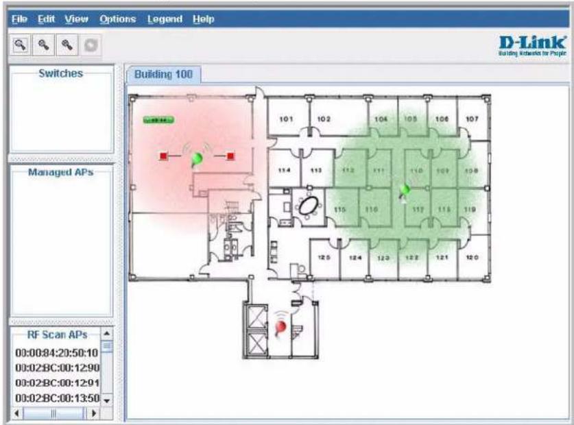
The WLAN Visualization tool provides an AP power display with color-coded channels to help you determine where to physically place access points to reduce interference or increase coverage on your WLAN.
D-LINK UNIFIED ACCESS SYSTEM TOPOLOGY
The WLAN network topology you use depends on the size and requirements of your network. Small-to-medium networks might require only one Unified Switch that manages a few D-Link Access Points. For larger networks that need greater roaming capabilities for wireless clients, a deployment with multiple peer switches that each manage several APs might be appropriate.
Single Unified Switch Deployment
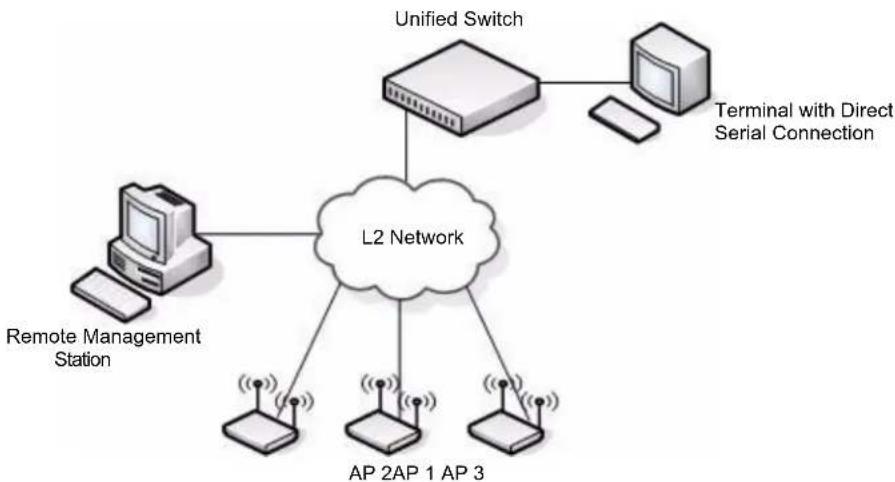
When you deploy a D-Link Access Point, the D-Link Unified Switch can automatically detect the AP and assign a default profile, which includes automatic RF channel selection and automatic power adjustment. Figure 2 shows a deployment with one D-Link Unified Switch that manages three D-Link Access Points.
Figure 2: Single Unified Switch with Layer 2 Roaming Support
flowchart
graph TD
    A["Unified Switch"] --> B["L2 Network"]
    C["Terminal with Direct Serial Connection"] --> B
    D["Remote Management Station"] --> B
    E["AP 2AP 1 AP 3"] --> B
    F["AP 2AP 1 AP 3"] --> B
When the APs are on the same subnet and have the same SSID, wireless clients can seamlessly roam among the three APs with no interruption in network access. The client keeps the same IP address and does not need to re-authenticate when it moves into the broadcast area of a different AP. Configuration changes to the APs are managed by the switch simultaneously or on a per-AP basis.
Peer Unified Switch Deployment
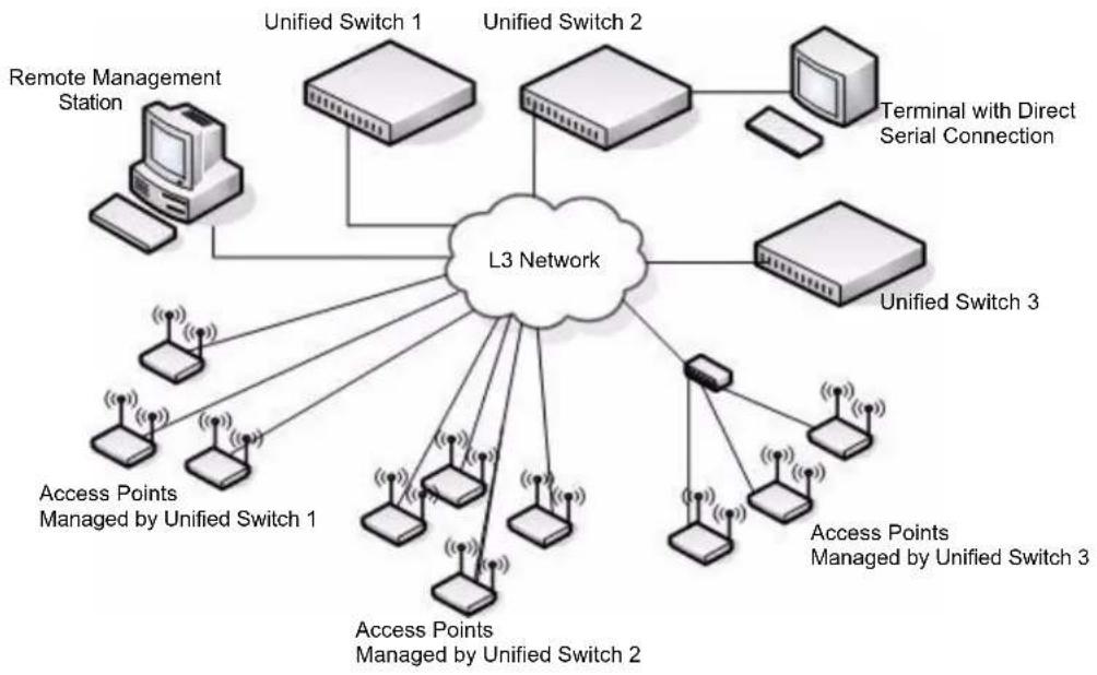
To support larger networks, you can configure up to four switches as peers, which increases the size and range of the WLAN. Figure 3 on page 25 shows a D-Link Unified Access System deployment that utilizes three peer Unified Switches. Each peer Unified Switch can manage up to 48 access points (DWS-3024 and DWS-3026) or 24 access points (DWS-3024L). The Unified Switch and the APs it manages do not need to be on the same subnet.
Figure 3: Peer Unified Switch with Layer 3 Roaming Support
flowchart
graph TD
    A["L3 Network"] --> B["Unified Switch 1"]
    A --> C["Unified Switch 2"]
    A --> D["Unified Switch 3"]
    A --> E["Terminal with Direct Serial Connection"]
    A --> F["Access Points Managed by Unified Switch 1"]
    A --> G["Access Points Managed by Unified Switch 2"]
    A --> H["Access Points Managed by Unified Switch 3"]
    A --> I["Remote Management Station"]
Peer Unified Switches share information about APs and allow Layer 3 roaming among them. To support this, peer Unified Switches establish IPv4 tunnels so that the wireless client keeps the same IP address even when the client associates with an access point in a different subnet. The Layer 3 roaming service allows wireless phone users to roam between access points connected to different subnets without dropping calls.
UNDERSTANDING THE USER INTERFACES
The D-Link Unified Access System enables centralized management of multiple wireless access points, which not only facilitates deployment and management, but also enhances security. The D-Link Unified Access System includes a set of comprehensive management functions for managing and monitoring the WLAN by using one of the following three methods:
- Web-based
• Command-Line Interface (CLI)
• Simple Network Management Protocol (SNMP)
Each of the standards-based management methods enables you to configure, manage, and control the components of the D-Link Unified Access System locally or remotely. Management is standards-based, with configuration parameters and a private MIB that provides control for functions not completely specified in the standard MIBs.
The method you use to configure and monitor the D-Link Unified Switch depends on your network size and requirements, and on your preference.
Using the Web Interface
The following Web browsers are supported for Web interface access to the switch:
- Microsoft ^ Internet Explorer version 6.x or 7.x (with up-to-date patch level for either major version)
- Mozilla Firefox version 2.x or 3.x
The administration Web browser must have JavaScript™ version not later than 1.6.0_18 enabled to support the interactive features of the administration interface.
Use the following procedures to log on to the Web Interface:
1 Open a Web browser and enter the IP address of the switch in the Web browser address field.
2 Enter the user name and password into the dialogue box that appears.
The user name and password are the same as those you use to log on to the command-line interface. By default, the user name is admin, and there is no password.
3 After the system authenticates you, the System Description page displays.
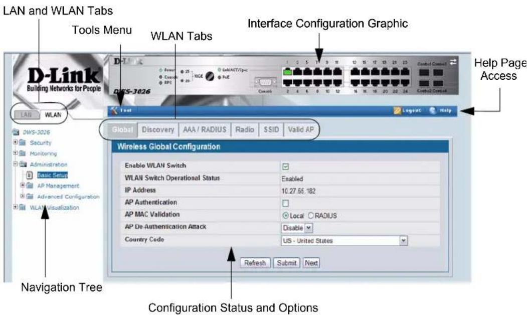
Figure 4 shows the layout of the D-Link Unified Switch Web interface. Each Web page contains three main areas: interface configuration graphic, the navigation tree, and the configuration status or options.
Figure 4: Web Interface Layout
Interface Configuration Graphic
The interface configuration graphic is a Java™ applet that displays the ports on the D-Link Unified Switch. This graphic appears at the top of each page to provide an alternate way to navigate to configuration and monitoring options.
Click the port you want to view or configure to see a menu that displays statistics and configuration options. Click the menu option to access the page that contains the configuration or monitoring options. Click Logout to log out of the Web Interface. From the Logout prompt, click Ok to save your changes and make the changes permanent. Click Cancel to close the Web Interface without saving your changes.
If you click the graphic but do not click a specific port, the main menu appears. This menu contains the same option as the navigation menu on the left side of the page.
Figure 5: Cascading Navigation Menu
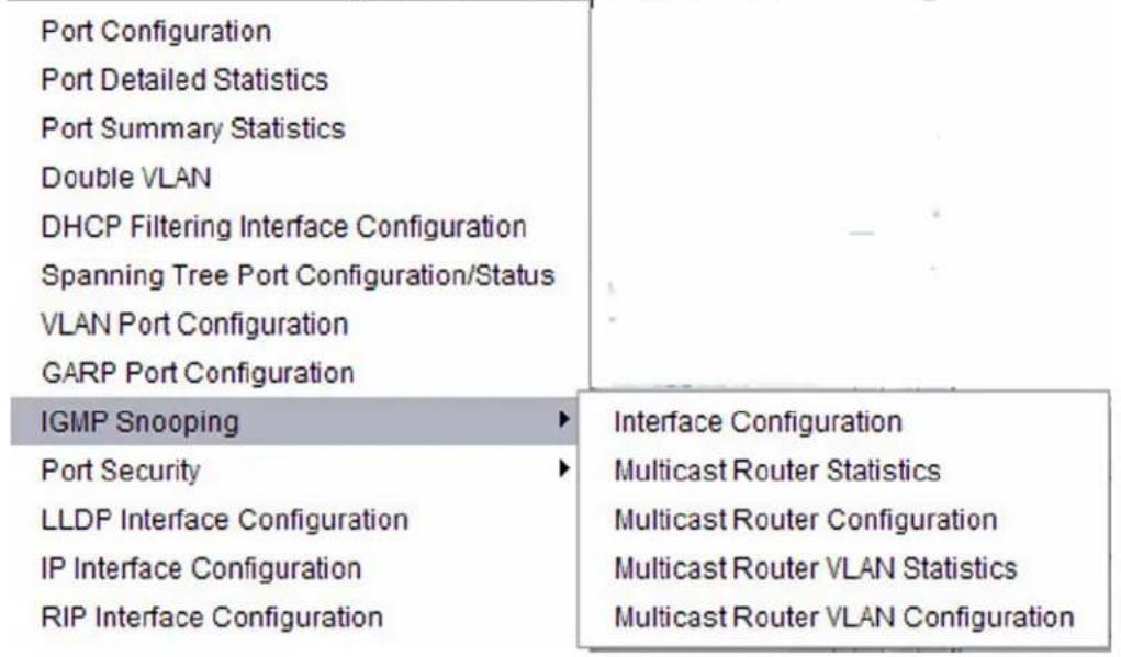
Navigation Menu
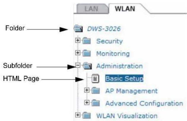
A hierarchical-tree view appears to the left of the panel. The tree consists of a combination of folders, subfolders, and configuration and status HTML pages. Click the folder to view the options in that folder. Each folder contains either subfolders or HTML pages, or a combination of both. Figure 6 shows an example of a folder, subfolder, and HTML page in the navigation menu. When you click a folder or subfolder that is preceded by a plus (+), the folder expands to display the contents. If you click an HTML page, a new page displays in the main frame. A folder or subfolder has no corresponding HTML page.
Figure 6: Hierarchical Tree Navigation Menu
Configuration and Monitoring Options
The panel directly under the graphic and to the right of the navigation menu displays the configuration information or status for the page you select. On pages that contain configuration options, you can input information into fields or select options from menus.
Each page contains access to the HTML-based Help that explains the fields and configuration options for the page. Many pages also contain command buttons.
The following command buttons are used throughout the pages in the Web interface:
- Clicking the Submit button sends the updated configuration to the switch. Configuration changes take effect immediately, but some changes are not retained across a power cycle unless you save them to the system configuration file.
- Clicking the Save button saves the current configuration to the system configuration file. When you click Save, changes that you have submitted are saved even when you reboot the system. To save the configuration, use the Save Changes link in the Tools menu.
- Clicking the Refresh button refreshes the data on the panel.
WLAN Tabs
Many of the pages in the WLAN folder contain tabs to simplify navigation and to group functions for a common feature. Click the tab to access a specific page.

Note: Other packages in the software suite do not use tabs in the Web interface.
Tools Menu
If you mouse over the Tool icon, a list of the following useful system tools appears:
- Reset Configuration
- Reset Password
- Reboot System
- Save Changes
- Download File
- Upload File
- Multiple Image Services
Each item in the list is a link to the Web page where you can perform the related task.
Using the Command-Line Interface
The command-line interface (CLI) is a text-based way to manage and monitor the system. You can access the CLI by using a direct serial connection or by using a remote logical connection with Telnet or SSH.
The CLI groups commands into modes according to the command function. Each of the command modes supports specific commands. The commands in one mode are not available until you switch to that particular mode, with the exception of the User EXEC mode commands. You can execute the User EXEC mode commands in the Privileged EXEC mode.
To display the commands available in the current mode, enter a question mark (?) at the command prompt. To display the available command keywords or parameters, enter a question mark (?) after each word you type at the command prompt.
If there are no additional command keywords or parameters, or if additional parameters are optional, the following message appears in the output:
Press Enter to execute the command
For more information about the CLI, see the D-Link CLI Command Reference.
The D-Link CLI Command Reference lists each command available from the CLI by the command name and provides a brief description of the command. Each command reference also contains the following information:
- The command keywords and the required and optional parameters.
- The command mode you must be in to access the command.
- The default value, if any, of a configurable setting on the device.
The show commands in the document also include a description of the information that the command shows.
Using SNMP
For D-Link Unified Switch software that includes the SNMP module, you can configure SNMP groups and users that can manage traps the SNMP agent generates.
The D-Link Unified Switch uses both standard public MIBs for standard functionality as well as a number of additional private MIBs for additional functionality supported by the switch. All private MIBs begin with a "DLINK-" prefix. The main object for interface configuration is in DLINK-SWITCHING-MIB, which is a private MIB. Some interface configurations also involve objects in the public MIB, IF-MIB.
SNMP is enabled by default. The System Description Web page, which is the page the displays after a successful login, and the show sysinfo command display the information you need to configure an SNMP manager to access the switch.
Any user can connect to the switch using the SNMPv3 protocol, but for authentication and encryption, you need to configure a new user profile. To configure a profile by using the CLI, see the SNMP section in the D-Link CLI Command Reference. To configure an SNMPv3 profile by using the Web interface, use the following steps:
1 Select LAN > Administration > User Accounts from the hierarchical tree on the left side of the Web interface.
2 Using the User menu, select Create to create a new user.
3 Enter a new user name in the User Name field.
4 Enter a new user password in the Password field and then retype it in the Confirm Password field.
To use SNMPv3 Authentication for this user, set a password of eight or more alphanumeric characters.
5 To enable authentication, use the Authentication Protocol menu to select either MD5 or SHA for the authentication protocol.
6 To enable encryption, use the Encryption Protocol menu to select DES for the encryption scheme. Then, enter an encryption code of eight or more alphanumeric characters in the Encryption Key field.
7 Click Submit.
To access configuration information for SNMPv1 or SNMPv2, click LAN > Administration > SNMP Manager and click the page that contains the information to configure.
WIRELESS SYSTEM FEATURES AND STANDARDS SUPPORT
In addition to core switching features, the D-Link Unified Switch supports the following features and standards:
- IP Tunneling
- Spanning Tree
• Auto detection and configuration of APs
• Automatic Peer-Switch Discovery
• Automatic or Manual RF Channel Assignment
• Automatic or Manual AP Power Adjustment - AP Authentication
- Client Authentication
- Load Balancing
• RF Scan and AP Sentry Mode - Dual Radio Support
-
Multiple Mode Support for Radios:
-
IEEE 802.11a
- IEEE 802.11b/g
- IEEE 802.11b/g/n
- IEEE 802.11a/n
- 2.4 GHz IEEE 802.11n
- 5 GHz IEEE 802.11n
- Dynamic Turbo 5Ghz
- Dynamic Turbo 2.4 Ghz
• IEEE 802.11h (TPC and DFS)
• Security Standard Support:
- WEP (64, 128)
- WEP (152)
- T K I P
- AES & CCMP
- Inhibit SSID broadcast
- WPA (Personal)
- WPA (Enterprise)
- WPA2 (Personal) 802.11i
- WPA2 (Enterprise) 802.11i
- MAC Authentication
- Multiple BSSID/VLANs
• Security and Authentication Settings per SSID
• VLAN Support
• IEEE 802.11d (Country Code)
- IEEE 802.11e (WMM)

Note: For the IEEE 802.11e, only Unscheduled Automatic Power Save Delivery (U-APSD), part of the 802.11e, is supported when DWL-8600APs are managed by a DWS-3000 switch.
- RADIUS support
- WLAN Visualization (NMS like product for APs)
- Mobility
-
Inter- and Intra- Subnet Fast Roaming
-
Key caching
- Tunneled and distributed forwarding
- Peer-to-peer WLAN switch roaming
- Intrusion Detection
- Rogue AP detection
- Rogue Client detection
- Station blacklisting
- Ad-hoc network detection
• Network Management
- SNMP v1, v2c, v3
- CLI
- SYSLOG
- Up to 24 APs (DWS-3024L) or 48 APs (DWS-3024 and DWS-3026) per switch
- Auto AP image download
- D-Link WLAN Private MIB
- Simultaneous AP upgrade
- Centralized data forwarding via tunneling for fast roaming and unified QoS
- AP RF Monitoring
- Configuration & Firmware Upload/Download
Each AP supports up to 16 virtual access points (VAPs) per radio for DWL-8600. You can configure a unique SSID and security policy on each VAP. The following list shows some of the D-Link Access Point features and standards support:
• WLAN and IEEE Standards
- IEEE 802.11a
- IEEE 802.11b
- IEEE 802.11d
- IEEE 802.11e (WMM)

Note: For the IEEE 802.11e, only Unscheduled Automatic Power Save Delivery (U-APSD), part of the 802.11e, is supported when DWL-8600APs are managed by a DWS-3000 switch.
- IEEE 802.11g
- IEEE 802.11h
- IEEE 802.11i (WPA2)
- IEEE 802.1X - 2001 Port Based Network Access Control
- IEEE802.3af PoE Support
- WLAN RF Features
- R F S c a n
- Transmit Power Control
- Load Balancing
- Dynamic Channel Assignment
- Dual Radio Support
- Atheros Dynamic Turbo 5Ghz
- Atheros Dynamic Turbo 2.4 Ghz
- TELEC 4.9GHZ 802.11a modes
- Wireless Statistics
- Virtual AP with Multiple BSSIDs/SSIDs
- WLAN AP Management
- CLI Management (SSH)
- Web Management (SSL support)
- T F T P
• WLAN Networking and QoS
- Switch/AP Discovery
- Tunneling
- WMM (802.11e)

Note: For the IEEE 802.11e, only Unscheduled Automatic Power Save Delivery (U-APSD), part of the 802.11e, is supported when DWL-8600APs are managed by a DWS-3000 switch.
- 802.1p (MAC layer QoS support)
- D S C P
- Dynamic VLANs
- MAC ACLs
- SpectralLink Priority Support
• WLAN Encryption and Security
- WEP
- T K I P
- AES & CCMP
- Rogue AP detection
- Ad-Hoc Client Detection
- Inhibit / Ignore SSID broadcast
- Weak IV avoidance
- MAC Authentication
- Port/IP blocking
- RADIUS support
- EAP
- PEAP
- TLS and TTLS
- WPA (Personal, Enterprise)
- WPA2 (Personal, Enterprise) 802.11i
- 802.1X Supplicant
- Client Authentication
- Firewall/IP filtering support
Section 3: Planning the D-Link Unified Access System Network
The D-Link Unified Access System provides continuous, high-speed access between your wireless and Ethernet devices. It is an advanced, scalable, standards-based solution for wireless networking. The D-Link Unified Access System enables wireless local area network (WLAN) deployment while providing state-of-the-art wireless networking features.
This chapter contains the following sections to help you plan your D-Link Unified Access System:
- "System Requirements"
- "WLAN Topology Considerations"
• "Network Planning to Support Layer 3 Roaming"
SYSTEM REQUIREMENTS
You accomplish the initial D-Link Unified Switch configuration by using a direct cable connection. After the initial configuration, you can manage the Unified Switch by using a Web-based user interface (UI), command line interface (CLI), or SNMP. The following list describes the minimum requirements you need to install and manage the D-Link Unified Switch:
- VT100 terminal or PC with terminal-emulation software
- Direct serial connection to the console port of the D-Link Unified Switch
- Remote system for management access with a Web browser, Telnet/SSH client, or SNMP manager
To support security and networking features in D-Link Unified Access System, you can use the following optional equipment on your network:
- A RADIUS server for authentication and accounting features for wireless clients, access points, and peer Unified Switches
• Network equipment that supports VLANs
• A DHCP server to dynamically assign network information to the switch and to all access points
• A Syslog server for external logging
Figure 7 shows a simple D-Link Unified Access System deployment with required and optional equipment for setup and operation.
Figure 7: D-Link Unified Access System Components
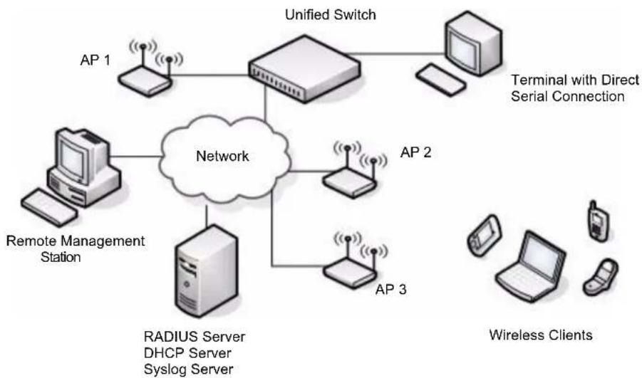
flowchart
graph TD
    A["Unified Switch"] --> B["Network"]
    C["AP 1"] --> B
    D["AP 2"] --> B
    E["AP 3"] --> B
    F["Remote Management Station"] --> B
    G["AP 4"] --> B
    H["AP 5"] --> B
    I["AP 6"] --> B
    J["AP 7"] --> B
    K["AP 8"] --> B
    L["AP 9"] --> B
    M["AP 10"] --> B
    N["Terminal with Direct Serial Connection"]
    O["Wireless Clients"]

Note: The Unified Switch has a built-in DHCP server. If you do not already have a DHCP server on your network, you can configure the Unified Switch to assign network information to network hosts.
As the figure shows, the wireless clients can be laptop computers, personal digital assistants (PDAs), smart phones, or any other hand-held, portable or stationary device equipped with a Wi-Fi adapter and supporting drivers. In order to connect to the access point, wireless clients need the software and hardware the following list describes:
- A portable or built-in Wi-Fi client adapter that supports one or more of the IEEE 802.11 modes in which you plan to run the access point. (IEEE 802.11a, 802.11b, 802.11g)
- Client software such as Microsoft Windows Supplicant configured to associate with the WLAN.
- Wireless security software that is compatible with the authentication mode the access point uses.
WLAN TOPOLOGY CONSIDERATIONS
The D-Link Unified Switch adds WLAN functionality to the base switching and IP routing features standard in most Layer 2/3 switches. Where you put the D-Link Unified Switch in your network depends on the size, requirements, and existing topology of your network. If you are adding a wireless network to an existing network, your requirements are different than the requirements of someone who does not have a sufficient LAN infrastructure.
Since the D-Link Unified Switch has Layer 2/3 switching functions as well as WLAN data and management functions, you can connect D-Link Access Points, wired PCs, or other network equipment such as hubs, routers, or other switches directly to the 10/100/1000 Mbps Ethernet ports on the switch. All connections to the D-Link Unified Switch must be wired connections since the switch does not have any radios.
In Figure 8, the D-Link Unified Switches are both LAN and WLAN switches that handle traffic from end users connected to the wired LAN as well as traffic from the D-Link Access Points. In the diagram, Building 1 and Building 2 have a D-Link Unified Switch on each floor.
Figure 8: Wiring Closet Topology
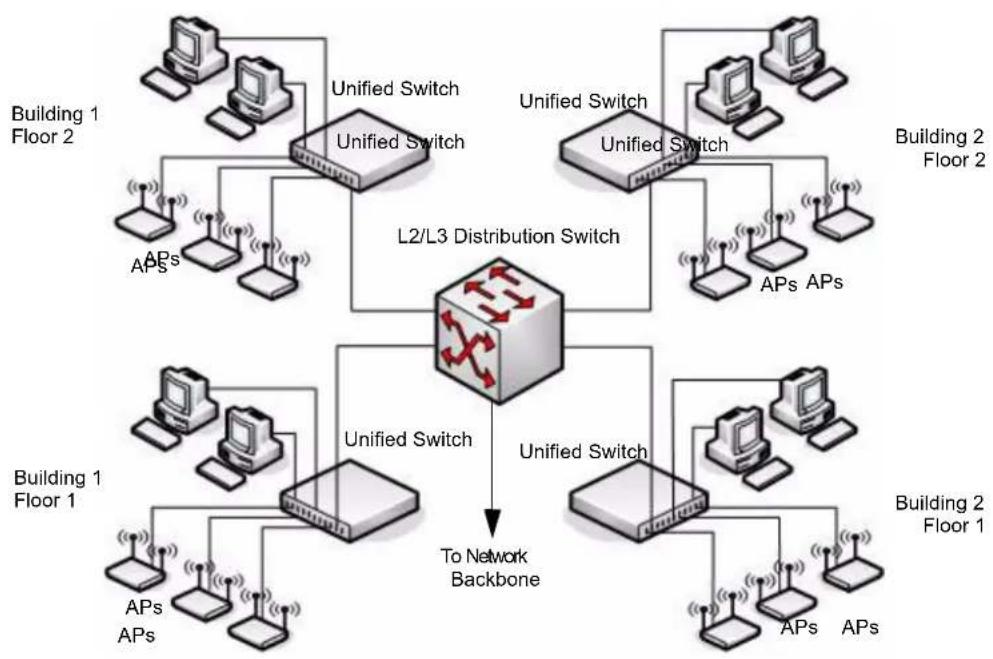
flowchart
graph TD
    subgraph_Building1_Floor2["Building 1 Floor 2"]
        A1["APs"] --> B1["Unified Switch"]
        A2["APs"] --> B2["Unified Switch"]
        A3["APs"] --> B3["Unified Switch"]
        B1 --> C["To Network Backbone"]
        B2 --> C
        B3 --> C
    end

    subgraph_Building2_Floor2["Building 2 Floor 2"]
        D1["APs"] --> E1["Unified Switch"]
        D2["APs"] --> E2["Unified Switch"]
        D3["APs"] --> E3["Unified Switch"]
        E1 --> F["L2/L3 Distribution Switch"]
        E2 --> F
        E3 --> F
    end

    subgraph_Building1_Floor1["Building 1 Floor 1"]
        G1["APs"] --> H1["Unified Switch"]
        G2["APs"] --> H2["Unified Switch"]
        H1 --> I["To Network Backbone"]
        H2 --> I
    end

    subgraph_Building2_Floor1["Building 2 Floor 1"]
        J1["APs"] --> K1["Unified Switch"]
        J2["APs"] --> K2["Unified Switch"]
        K1 --> L["To Network Backbone"]
        K2 --> L
    end
The four D-Link Unified Switches are in the same peer group. This allows wireless clients to roam between floors and between buildings without the need to re-authenticate. Additionally, each Unified Switch shares its list of managed APs and wireless clients with the switches in the peer group so that the APs and wireless clients are not reported as rogues (unknown).
The topology in Figure 8 works well if you need to add, upgrade, or replace LAN switches on your network.

Note: When tunneled clients are used in conjunction with peer switches, one of the peer switches must be configured as a default gateway for the tunneled clients. Normally the default gateway routes all traffic from the client's subnet to other subnets, however in a peer switch network the Unified Switch that manages the AP to which the client is associated, routes the frames into the remote subnets. This means that each peer switch must have routing table entries that enable it to route frames to every subnet in the network.
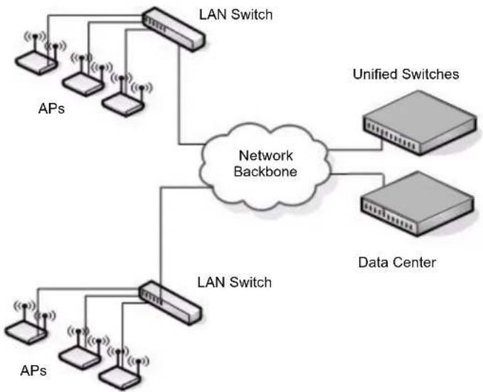
Figure 9 shows two D-Link Unified Switches in the network data center. In this deployment, the switches do not connect directly to APs or end-user nodes.
Figure 9: Data Center Topology
flowchart
graph TD
    A["APs"] --> B["LAN Switch"]
    C["APs"] --> D["LAN Switch"]
    E["APs"] --> F["LAN Switch"]
    G["APs"] --> H["LAN Switch"]
    I["Data Center"] --> J["Unified Switches"]
    K["Network Backbone"] --> L["APs"]
    K --> M["APs"]
    K --> N["APs"]
    K --> O["APs"]
    K --> P["APs"]
    K --> Q["APs"]
The data center topology is a good solution in networks where the goal is to add a wireless LAN to a network with minimal changes to the existing network. Traffic from wireless clients to the APs is either tunneled through the Unified Switch or tagged with a VLAN ID by the AP and handled accordingly. If the traffic is tagged, it might not pass through the Unified Switch.
Access Point-to-Switch Discovery
To enable the AP and Unified Switch to discover each other, you can use one of the following four methods:
- Enter the IP address of the Unified Switch into the AP
- Enter the IP address of the AP into the Unified Switch
- Configure the DHCP server to pass the IP address of the Unified Switch to the AP in DHCP option 43
• Use the D-Link Wireless Device Discovery Protocol
The AP-to-switch discovery method you use depends on your network topology. For example, if the Unified Switch and AP are in the same Layer 2 multicast domain, we recommend that you use the D-Link Wireless Device Discovery Protocol.
These options are discussed in more detail in "Discovering Access Points and Peer Switches" on page 58.
Access Point Placement
D-Link Access Points can be on the same subnet as the switch or on a different subnet. You can connect the AP directly to the Unified Switch or to another networking device. The range of the D-Link Access Point is about 100 meters, but the range is affected by various environmental factors.
To maximize the range, use the following guidelines for the placement of the AP:
-
Place the AP in an area where you expect wireless clients will operate.
• Elevated locations, such as on top of a shelf are preferred to increase line-of-sight access. -
Avoid placing the AP near sources of interference, such as PCs, microwaves, and 2.4 GHz cordless phones.
- Keep the AP away from large metal surfaces.
- Position the antenna horizontally to increase the up-and-down range, or position it vertically to increase side-to-side coverage.
- When APs are within broadcast range of each other, use non-interfering RF channels (five channels apart for the 802.11b/g radio).
How close you place APs to each other depends on the RF transmission power level, the number of wireless clients on your network, and the channels the APs use. The RF signal transmission power level directly affects the broadcast range of the AP signal. If the power level is too low, wireless clients will not detect the signal or experience poor WLAN performance. If the power level is too high, the RF signal might interfere with other APs within range. If the RF signal broadcasts beyond the physical confines of your building or network, it increases the security threat to the network.
When the power level is high and RF broadcast area is larger, more wireless clients can detect the signal and associate with the AP. An increase in the number of wireless clients that associate with the AP generally means that the amount of traffic the AP receives and transmits increases as well. You can limit the network utilization level allowed on an AP to prevent wireless clients from experiencing slower network speeds. However, once the network utilization is reached, new clients are unable to associate with the AP. If an AP frequently reaches the network utilization limit, it might indicate that you should add another AP nearby. You can configure the APs to automatically adjust the power and channel to the needs of the network environment.
NETWORK PLANNING TO SUPPORT LAYER 3 ROAMING
With the D-Link Unified Access System, mobile stations can maintain their IP connections while roaming from one access point to another even when these access points are attached to different IP subnets. This feature enables Voice over IP (VoIP) deployments on 802.11 subnetted networks.
It is often necessary to subdivide the enterprise IPv4 network into several subnets. An access point may be directly attached to the Unified Switch or it may be located several router hops away from the Unified Switch.
To support layer 3 roaming, it is necessary to keep the wireless client's IP address unchanged while it roams over different subnets. This guarantees seamless roaming as the IP changeover process does not take place while wireless clients roam across subnet borders.
The D-Link Unified Access System provides two ways to prevent the IP address of a roaming client from changing:
1 You can associate the SSID for roaming with a VLAN and configure the network devices on your network to allow VLAN trunking across different subnets. By doing this, the client will always stay in the same VLAN and retain the same IP address while it roams.
This approach is appropriate when it is not difficult to configure VLAN trunking on devices in the network.
2 You can associate the SSID for roaming with a tunneled subnet. In this case, the switch uses IP tunneling to establish a link between itself and the access point it manages. The switch routes all IPv4 unicast frames so that the wireless networks are perceived as locally attached networks by the Unified Switch.
Routing must be enabled on the switch to support L3 roaming.
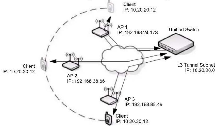
Figure 10 shows a single wireless client as it roams among three APs in three different subnets. A D-Link Unified Switch controls the three APs. When the wireless client connects to any of the APs, it receives an IP address from the Unified Switch that is in the L3 Tunnel subnet. As the client roams among the APs, it maintains its connection to the WLAN and keeps the same IP address that the switch originally assigned it. All traffic the client sends and receives goes through the switch.
Figure 10: Inter-Subnet Roaming
flowchart
graph TD
    A["Client IP: 10.20.20.12"] --> B["AP 1"]
    B --> C["Unified Switch"]
    C --> D["L3 Tunnel Subnet IP: 10.20.20.0"]
    D --> E["AP 2"]
    E --> F["Client IP: 10.20.20.12"]
    F --> G["AP 3"]
    G --> H["Client IP: 10.20.20.12"]
    H --> I["AP 1"]
    I --> J["Unified Switch"]
    J --> K["AP 2"]
    K --> L["Client IP: 192.168.38.66"]
    L --> M["AP 3"]
    M --> N["Client IP: 192.168.85.49"]
    N --> O["AP 1"]
    O --> P["Client IP: 192.168.24.173"]
    P --> Q["AP 2"]
    Q --> R["Client IP: 10.20.20.12"]
    R --> S["AP 3"]
    S --> T["Client IP: 10.20.20.12"]
    T --> U["AP 1"]
    U --> V["Client IP: 10.20.20.12"]
    V --> W["AP 2"]
    W --> X["Client IP: 192.168.38.66"]
    X --> Y["AP 3"]
    Y --> Z["Client IP: 192.168.85.49"]
    Z --> AA["AP 1"]
    AA --> AB["Client IP: 10.20.20.12"]
In the tunneling configuration, you can use ACL lists and QoS parameters to ensure that time-sensitive traffic, such as VoIP, takes priority over other WLAN traffic.
For many IP phone systems, you must connect a call server to a wired port on the L3 tunnel subnet. You must also either configure DHCP relay on the switch or configure the switch to be a DHCP server. APs, peer switches, and other routers cannot be connected to the L3 tunnel subnet.
For more information about L3 tunnelling and how to configure it, see "Configuring a VAP for L3 Tunnels" on page 95 and Appendix Appendix C:, "L3 Roaming Example" on page 213.
Section 4: Installing the Hardware
This chapter provides instructions for installing the D-Link DWS-3024, DWS-3024L, and DWS-3026 switch hardware. The following sections describe this installation process:
- "Hardware Overview"
- "Front Panel Components"
- "LED Indicators"
- "Rear Panel Description"
- "Side Panels"
- "Installation"
- "Package Contents"
- "Installation Guidelines"
- "Installing the Switch without the Rack"
- "Installing the Switch in a Rack"
- "Powering On the Switch"
- "Installing the SFP ports"
- "Installing the Optional Modules"
- "Connecting to the External Redundant Power System"
- "Connecting the Switch"
- "Connecting the Switch to the Network"
- "Connecting the Switch and AP Directly"
- "Connecting the Switch and AP through the L2/L3 Network"
- "Connecting to the Core Network"
HARDWARE OVERVIEW
This section describes the font, back, and side panels and the LED indicators on the switch. The DWS-3024/DWS-3024L and DWS-3026 have slightly different front and back panels based on the available features.
Front Panel Components
The front panel of the Switch consists of LED indicators for Power, Console, RPS, PoE, and Link/Act/Speed for each port on the Switch including 10GE Ports for optional modules and SFP port LEDs. Table 3 describes the LED indicators in more detail.
Figure 11: Front Panel View of the DWS-3024L as Shipped

Figure 12: Front Panel View of the DWS-3024 as Shipped

Figure 13: Front Panel View of the DWS-3026 as Shipped

LED Indicators
The Switch supports LED indicators for Power, Console, RPS, PoE, and Port LEDs including 10GE port LEDs for optional module inserts on the DWS-3026.
Figure 14: LED Indicators on DWS-3024L
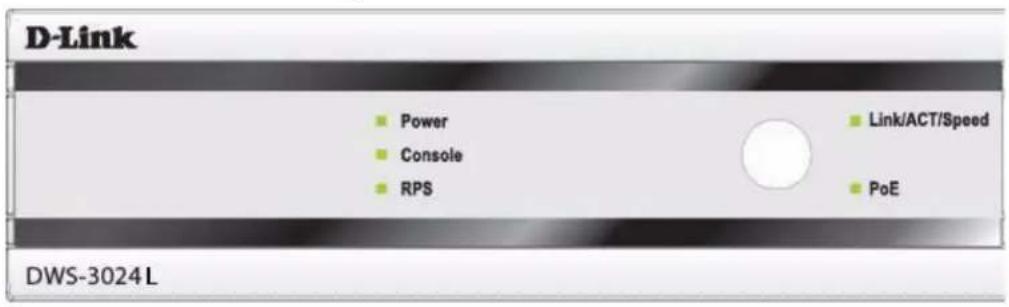
Figure 15: LED Indicators on DWS-3024
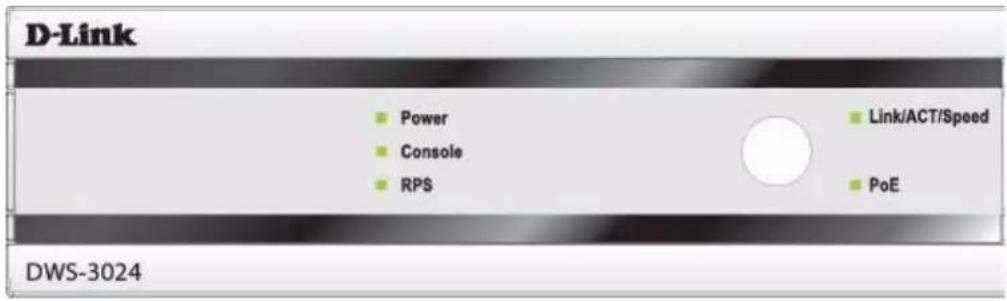
Figure 16: LED Indicators on DWS-3026
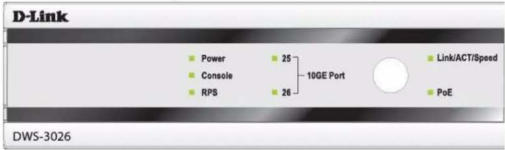
The following table describes the LEDs and the Mode Select Button on the front panel of each Switch.
Table 3: LED Description
| LED Description | |
| Power | This LED lights green after powering the Switch on to indicate the ready state of the device. The indicator is dark when the Switch is no longer receiving power (i.e powered off). |
| Console | This LED blinks green during the Power-On Self Test (POST). When the POST is finished, the LED goes dark. The indicator lights steady green when an active console link is in session via the RS-232 console port. |
| RPS | This LED lights when the internal power has failed and the RPS has taken over the power supply to the Switch. Otherwise, it remains dark. |
| Link/Act/Speed and PoE Mode | You can change the mode of the LEDs over each port to display the information about the link, activity, and speed of a port or whether 802.3af Power Over Ethernet (PoE) is supporting devices attached to the port.To change the LED mode from Link/Act/Speed to PoE and vice versa, press the LED Mode Select Button. |
| Port LEDs | One row of LEDs for each port is located above the ports on the front panel. The indicator above the left side of a port corresponds to the port below the indicator in the upper row of ports. The indicator above the right side of a port corresponds to the port below the indicator in the lower row of ports. The port LEDs show information about link, activity, and speed on the port or Power over Ethernet usage on the port, depending on the LED mode you select.For Link/Act/Speed Mode:Solid Green—Indicates a valid 1000Mbps link on the port, while a blinking green light indicates activity on the port (at 1000Mbps).Solid Amber—Indicates a valid 10 or 100Mbps link on the port.Blinking Amber—Indicates activity on the port (at 100Mbps).Off—No link/activity on the port.For PoE Mode:Solid Green—Power feeding (802.3af-compliant PD was detected).Blinking Amber—PoE port ERROR (non-standard PD connected, Under load state according to 802.3af (current is below 1 min), Overload state according to 802.3af (current is above 1 cut), hardware problems preventing port operation, power budget exceeded, short condition was detected at a port delivering power, temperature overload at the port, succession of Underload and Overload states caused port shutdown (may be caused by a PD's DC/DC fault)...etc.)Off—No power feeding (no PD detected, or no connection) |
| 10GE Port LEDs | (DWS-3026 only) A steady green light denotes a valid link on the port while a blinking green light indicates activity on the port. These LEDs remain dark if there is no link/activity on the port. |
| Combo SFP Ports | The LED indicators for the Combo ports are located above the ports and numbered 1 – 4 for Combo 1, Combo 2, Combo 3, and Combo 4 ports. A steady green light indicates a valid link on the port while a blinking green light indicates activity on the port. These LEDs remain dark if there is no link/activity on the port. |
Rear Panel Description
The AC power connector is a standard three-pronged connector that supports the power cord. Plug the female connector of the provided power cord into this socket, and plug the male side of the cord into a power outlet. The Switch automatically adjusts its power setting to any supply voltage in the range from 100 \~ 240 VAC at 50 \~ 60 Hz.
The rear panel also includes an outlet for an optional external power supply. When a power failure occurs, the optional external RPS will immediately and automatically assume the power supply for the Switch.
The rear panel of the DWS-3024/DWS-3024L contains an AC power connector, a system fan vent, and a redundant power supply connector.
Figure 17: Rear panel view of DWS-3024/DWS-3024L

natural_image
Back panel view of a network device showing four labeled ports: two connected to a grid and one with a port (no text or symbols visible)The rear panel of the DWS-3026 contains an AC power connector, a system fan vent, a redundant power supply connector and two empty slots for optional 10GE module inserts.
Figure 18: Rear panel view of DWS-3026

natural_image
Front view of a computer rack with indicator lights, connectors, and power socket (no text or symbols)Side Panels
The system fans and heat vents located on each side of the Switch dissipate heat. Do not block these openings. Leave at least 6 inches of space at the rear and sides of the Switch for proper ventilation. Without proper heat dissipation and air circulation, system components might overheat, which could lead to system failure and severely damage components.
INSTALLATION
This section describes how to install the Switch on a flat surface or in a standard equipment rack. It also describes how to install the optional components for the Switch.
Package Contents
Open the shipping carton of the Switch and carefully unpack its contents. The carton should contain the following items:
1 One Switch
2 One AC power cord
3 Mounting kit (two brackets and screws)
4 Four rubber feet with adhesive backing
5 RS-232 console cable
6 One CD Kit for DWS-3000 Series D-Link Unified Access System User Manual and D-Link CLI Command Reference
7 Registration card & China Warranty Card (for China only)
If any item is missing or damaged, please contact your local D-Link Reseller for replacement.
Installation Guidelines
Please follow these guidelines for setting up the Switch:
• Install the Switch on a sturdy, level surface that can support at least 6.6 lb. (3 kg) of weight. Do not place heavy objects on the Switch.
- The power outlet should be within 1.82 meters (6 feet) of the Switch.
• Visually inspect the power cord and see that it is fully secured to the AC power port. - Make sure that there is proper heat dissipation from the Switch and adequate ventilation around the Switch. Leave at least 10 cm (4 inches) of space at the front and rear of the Switch for ventilation.
• Install the Switch in a fairly cool and dry place for the acceptable temperature and humidity operating ranges.
• Install the Switch in a site free from strong electromagnetic field generators (such as motors), vibration, dust, and direct exposure to sunlight. - When installing the Switch on a level surface, attach the rubber feet to the bottom of the device. The rubber feet cushion the Switch, protect the casing from scratches, and prevent it from scratching other surfaces.
Installing the Switch without the Rack
First, attach the rubber feet included with the Switch if installing on a desktop or shelf. Attach these cushioning feet on the bottom at each corner of the device. Allow enough ventilation space between the Switch and any other objects in the vicinity.
Figure 19: Prepare Switch for Installation on a Desktop or Shelf
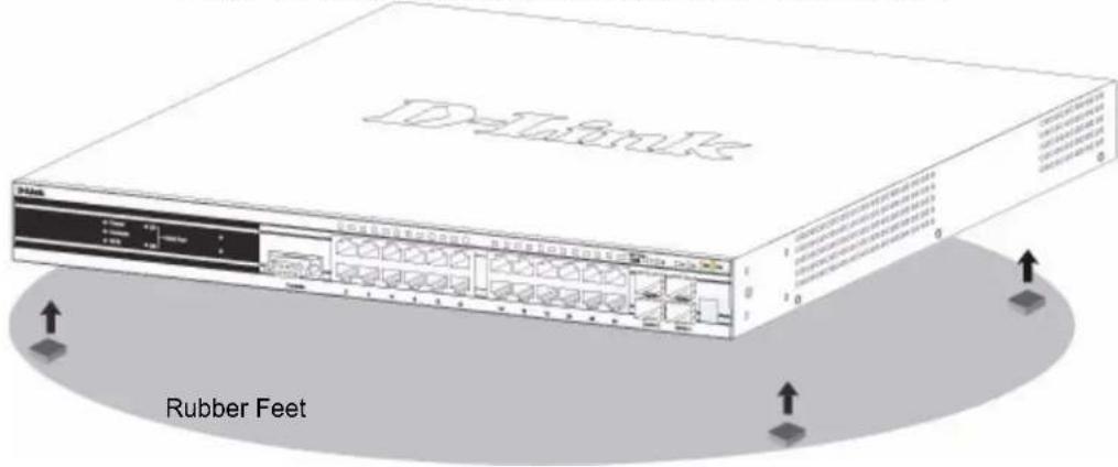
Installing the Switch in a Rack
The Switch can be mounted in a standard 19" rack. Use the following diagrams as a guide.
Figure 20: Fasten Mounting Brackets to Switch
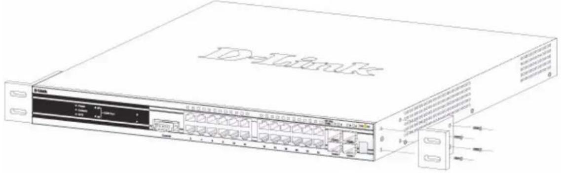
Fasten the mounting brackets to the Switch using the screws provided. With the brackets attached securely, the Switch can be mounted in a standard rack as shown in Figure 21.
Figure 21: Mounting the Switch in a Standard 19" Rack
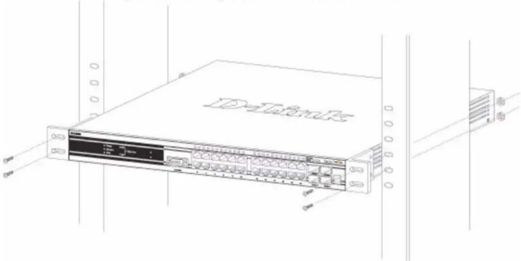
natural_image
Line drawing of a network switch device with ports and connectors, no text or symbols presentPowering On the Switch
Plug one end of the AC power cord into the power connector of the Switch and the other end into the local power source outlet.
After powering on the Switch, the LED indicators will momentarily blink. This blinking of the LED indicators represents a reset of the system.
Power Failure
As a precaution, in the event of a power failure, unplug the Switch. When power is resumed, plug the Switch back in.
Installing the SFP ports
The DWS-3000 series switches are equipped with SFP (Small Form-factor Pluggable) ports, which are to be used with fiber-optical transceiver cabling in order to uplink various other networking devices for a gigabit link that may span great distances. These SFP ports support full-duplex transmissions, have auto-negotiation and can be used with DEM-310GT (1000BASE-LX), DEM-311GT (1000BASE-SX), DEM-314GT (1000BASE-LH) and DEM-315GT (1000BASE-ZX) transceivers. See the figure below for installing the SFP ports in the Switch.
Figure 22: Inserting the Fiber-Optic Transceivers into the Switch
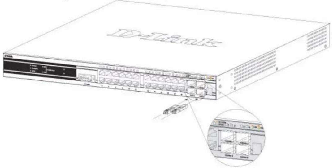
Installing the Optional Modules
The rear panel of the DWS-3026 includes two open slots that may be equipped with the DEM-410X 1-port 10GE XFP uplink module, or a DEM-410CX 1-port 10GBASE-CX4 uplink module, both sold separately.
Adding the DEM-410X optional module allows the switch to transmit data at a rate of ten gigabits per second. The module port(s) are compliant with standard IEEE 802.3ae, support full-duplex transmissions only and must be used with XFP MSA-compliant transceivers.
The DEM-410CX uses copper wire medium, not optic fiber and therefore has a transmit length limit up to 1 meters. Compliant with the IEEE802.3ak standard, this module uses a 4-lane copper connector for data transfer in full-duplex mode.
To install these modules in the DWS-3026 Switch, follow the steps listed in this section.

Caution! Before adding the optional module, make sure to disconnect all power sources connected to the Switch. Failure to do so may result in an electrical shock, which may cause damage, not only to the individual but to the Switch as well.
At the back of the Switch to the left are the two slots for the optional modules. These slots must be covered with the faceplate if the slots are not being used. To install a module in an available slot, remove the faceplate by loosening the screws and pulling off the plate.
The front panels of the available modules are shown here:
Figure 23: Front Panel of the DEM-410X
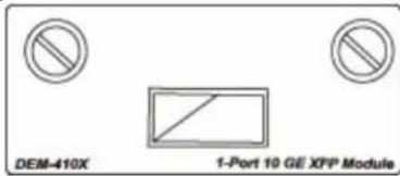
Figure 24: Front Panel of the DEM-410CX
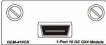
Install the Module
Unplug the Switch before removing the faceplate covering the empty slot. To install the module, slide it in to the available slot at the rear of the Switch until it reaches the back, as shown in the following figure. Gently, but firmly push in on the module to secure it to the Switch. The module should fit snugly into the corresponding receptors.
Figure 25: Inserting the optional module into the Switch (DWS-3026)
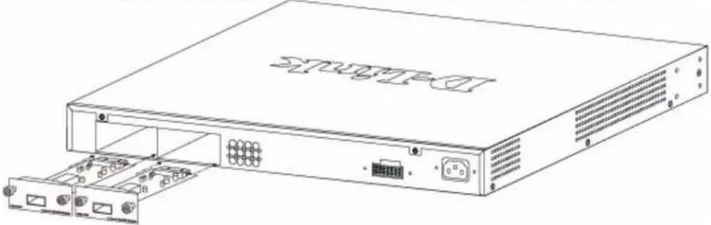
natural_image
Line drawing of a network device chassis with ports and connectors (no text or symbols)Now tighten the two screws at adjacent ends of the module into the available screw holes on the Switch. The upgraded Switch is now ready for use.
Figure 26: DWS-3026 with optional DEM-410X module installed
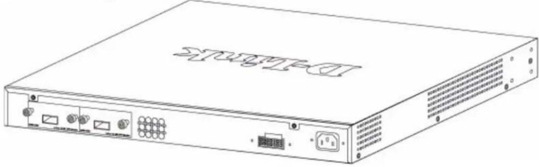
natural_image
Line drawing of a network switch device with ports and connectors (no text or symbols)Connecting to the External Redundant Power System
The Switch supports an external redundant power system (RPS). The diagrams below illustrate a proper RPS power connection to the Switch. Please consult the documentation for information on power cabling and connectors and setup procedure.
Figure 27: RPS Connector
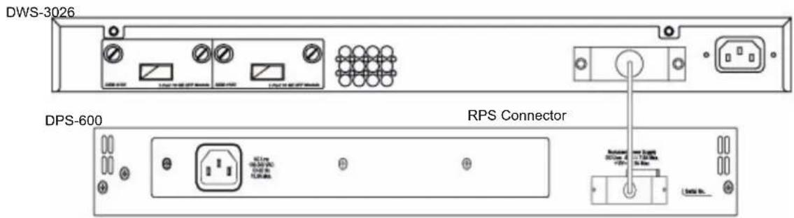
CONNECTING THE SWITCH
This section describes how to connect the following nodes:
- Switch to the network
• AP directly to the Switch - AP to the Switch through the L2/L3 network
- Switch through the 10GB uplink to the network core

Note: All 24 high-performance N-Way Ethernet ports can support both MDI-II and MDI-X connections.
Connecting the Switch to the Network
You can use any of the 1000BASE-T ports, 10GB ports, or fiber-optic ports to connect the Switch to your network. The type of port you use to connect the switch depends on your network requirements and the type of node to which you connect the Switch, which might be a hub, router, or another switch.
There is a great deal of flexibility on how connections are made using the appropriate cabling.
- Connect a 10BASE-T hub or switch to the Switch via a twisted-pair Category 3, 4 or 5 UTP/STP cable.
- Connect a 100BASE-TX hub or switch to the Switch via a twisted-pair Category 5 UTP/STP cable.
- Connect 1000BASE-T switch to the Switch via a twisted pair Category 5e UTP/STP cable.
- Connect a switch supporting a fiber-optic uplink to the Switch's SFP ports via fiber-optic cabling.
- Change the Switch to PoE mode using the Mode Select button. When in PoE Mode, the Switch works with all D-Link 802.3af capable devices.
The Link/Act LEDs for each UTP port will light green or amber when the link is valid. A blinking LED indicates packet activity on that port.
Connecting the Switch and AP Directly
You can connect one or more DWL-3500AP, DWL-8500AP, or DWL-8600AP access points directly to the Switch by using a straight-through or crossover UTP cable.
Figure 28: Switch and AP Connected Directly
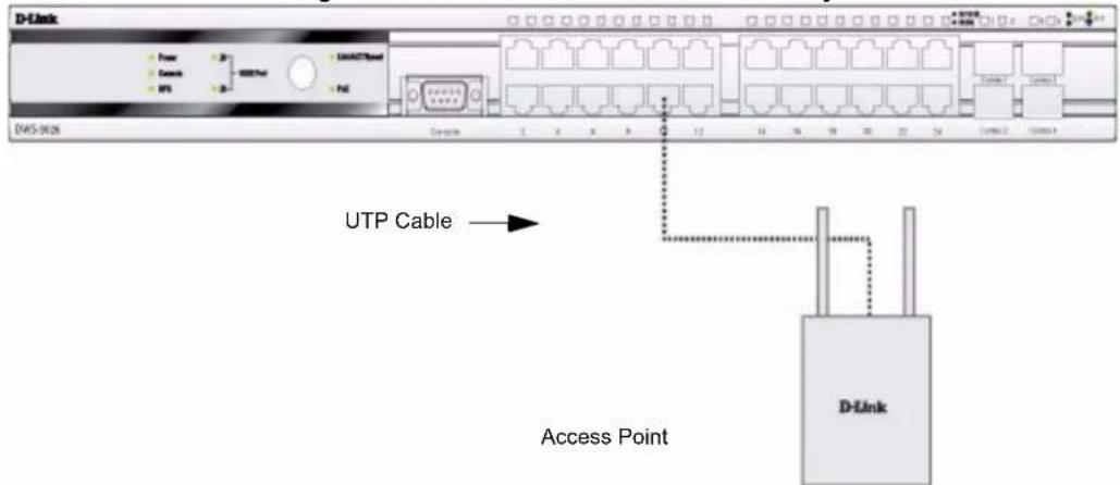
Connecting the Switch and AP through the L2/L3 Network
The Switch can discover and manage APs whether they are directly connected, connected through a device in the same subnet, or connected to different subnets.
Figure 29: Switch and APs Connected Through Network
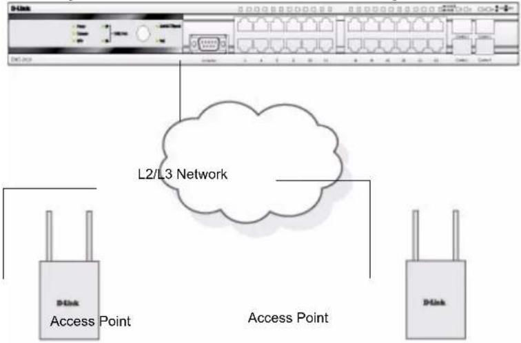
flowchart
graph TD
    A["D-Link"] --> B["Access Point"]
    C["D-Link"] --> D["Access Point"]
    B --> E["L2/L3 Network"]
    D --> E
    E --> F["Port 1"]
    E --> G["Port 2"]
    E --> H["Port 3"]
    E --> I["Port 4"]
    E --> J["Port 5"]
    E --> K["Port 6"]
    E --> L["Port 7"]
    E --> M["Port 8"]
    E --> N["Port 9"]
    E --> O["Port 10"]
Connecting to the Core Network
The optional 10GB ports on the DWS-3026 are ideal for uplinking to the core network. Connections to the Gigabit Ethernet ports are made using a fiber-optic cable or Category 5e copper cable, depending on the type of port. A valid connection is indicated when the Link LED is lit.
Figure 30 shows the rear panel of the DWS-3026 with the optional DEM-410X module.
Figure 30: Switch Connected to Network Core
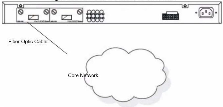
Section 5: Installing the D-Link Unified Access System
This chapter contains the following sections to help you install your D-Link Unified Access System network:
- "System Deployment Overview"
- "Connecting the Switch to the Network"
- "Enabling the WLAN Features on the Switch"
- "Preparing the Access Points"
• "Discovering Access Points and Peer Switches" - "Authenticating and Validating Access Points"
SYSTEM DEPLOYMENT OVERVIEW
To setup and deploy the D-Link Unified Access System solution, use the following general steps:
1 Plan the WLAN network topology.
Decide where to locate each access point to maximize accessibility to the WLAN by wireless clients and to minimize radio frequency (RF) interference by other access points. You should also determine how to integrate the D-Link Unified Switch into your existing network topology. For more information about planning the WLAN topology, see "WLAN Topology Considerations" on page 34.
2 Install and configure the D-Link Unified Switch.
To install and configure the switch, you need a serial connection to the switch, or you must connect to the switch from a host in the same subnet as the switch default IP address (10.90.90.90/8). From the initial connection to the switch, you can configure basic network information or enable the DHCP client on the switch to acquire this information automatically.
3 Enable the WLAN switch function and assign an IP address to the WLAN switch interface.
The WLAN features on the switch are enabled by default. The WLAN feature must be enabled in order for the switch to discover and validate D-Link Access Points. If the routing mode is disabled, the Unified Switch function uses the IP address of the network interface. If routing is enabled, the switch uses a loopback or routing interface for the wireless functions. Changing the IP address of the network interface automatically disables and re-enables the wireless function. Enabling routing also disables and re-enables the wireless function.
4 Configure the default AP Profile settings that the access point will use after the switch validates it.
When the switch successfully validates an access point, it sends the AP Profile to the access point. The AP Profile contains all of the access point configuration information, such as the radio, security, and SSID settings. You can configure all of the AP settings before or after the switch validates an AP. For information about configuring the default AP profile, see Chapter , “Configuring Access Point Settings” on page 77.
5 Prepare and deploy D-Link Access Points and enable AP-to-switch discovery.
After you connect an AP to the network and it obtains an IP address (either statically or dynamically by using DHCP), the Unified Switch can automatically discover the AP. However, if your network uses IEEE 802.1X authentication or you require the AP to be authenticated by the switch upon discovery, you must log on to the AP and configure security information.
6 Authenticate and validate the APs.
You can optionally configure the Unified Switch so that it only manages APs that it authenticates. You can use the local database or an external RADIUS database for AP authentication. Whether or not you require AP-to-Unified Switch authentication, the switch must be able to validate an AP before it can manage the AP. For the switch to validate the AP, you must add the MAC address of each AP to the AP database on the switch or to the database on an external RADIUS
server.
Once you validate the AP, you can use the switch to manage the AP and to view client associations, status, and statistics. If you follow the procedures in this chapter, the APs will have the default configuration profile. The default AP Profile settings are listed in Appendix A "D-Link Unified Access System Default Settings".

Caution! The default AP profile does not use a security mechanism for wireless client associations. All wireless clients will be able to connect to an AP and access your network.
To prevent unauthorized access to the network by wireless clients, you can configure security on the default profile before you deploy the APs, or you can create additional AP profiles to assign the APs when you add them to the Valid AP database. For information about how to configure default profile settings, see Chapter, "Configuring Access Point Settings" on page 77.
You can use the switch to create multiple AP profiles to assign the APs that you deploy on your network. For each profile, you can define information such as RF configuration, QoS configuration, and virtual AP (VAP) configuration. For information about AP profiles, see "AP Profiles, Networks, and the Local Database" on page 77. For information about creating and configuring a new AP profile, see "Creating, Configuring, and Managing AP Profiles" on page 153.
CONNECTING THE SWITCH TO THE NETWORK
After you perform the physical hardware installation, you need to connect the D-Link Unified Switch to the network. The default IP address of the switch is 10.90.90.90/8, and DHCP is disabled by default. If you want to enable DHCP on the switch or assign a different static IP address, you must connect to the switch and change the default settings.
You can connect to the switch through Telnet or a Web browser from a host on the 10.0.0.0/8 network, or you can connect to the switch through the console port (RS-232 DCE). After you connect to the switch, you can provide network information or enable the DHCP client.
To connect to the switch from a host on the 10.0.0.0 network, enter the default IP address of the switch (10.90.90.90) into the address field of a Web browser or a Telnet client.
To connect to the console port and provide network information, use the following steps:
1 Using a null-modem cable, connect a VT100/ANSI terminal or a workstation to the console (serial) port.
If you attached a PC, Apple, or UNIX workstation, start a terminal-emulation program, such as HyperTerminal or TeraTerm.
2 Configure the terminal-emulation program to use the following settings:
- Baud rate: 115,000 bps
- Data bits: 8
- Parity: none
- Stop bit: 1
- Flow control: none
3 Press the return key, and the User: prompt appears.
Enter admin as the user name. There is no default password. Press ENTER at the password prompt if you did not change the default password.
After a successful login, the screen shows the (switch-prompt) > prompt.
4 At the (switch-prompt) > prompt, enter enable to enter the Privileged EXEC command mode. There is no default password to enter Privileged EXEC mode. Press ENTER at the password prompt if you did not change the default
password.
The command prompt changes to (switch-prompt) #.
5 Configure the network information.
- To use a DHCP server to obtain the IP address, subnet mask, and default gateway information, enter network protocol dhcp.
- To use a BootP server to obtain the IP address, subnet mask, and default gateway information, enter network protocol bootp.
- To manually configure the IP address, subnet mask, and default gateway, enter network parms
[ ], for example: network parms 192.168.2.23 255.255.255.0 192.168.2.1
The default gateway is an optional parameter, so you do not need to enter an address to execute the command.
To view the network information, enter show network.
6 To save these changes so they are retained during a switch reset, enter the following command:
write
Once the D-Link Unified Switch is connected to the network, you can use the IP address for remote access to the switch by using a Web browser or through Telnet or SSH.
Null User Authentication
The null user authentication is allowed when the switch's administrator username is admin (case insensitive) and password is blank. The administrator can also login to the switch Web UI and serial console by using blank username and blank password. The null user has the same privileges as the admin user. The null user authentication is disallowed in the following cases:
- When the password of the admin user has been changed to a non-blank password
- When the admin username has been changed to a username other than admin.
ENABLING THE WLAN FEATURES ON THE SWITCH
In order for the Unified Switch to be able to discover and manage access points, the WLAN switch and its operational status must both be enabled. The WLAN component is enabled by default.
When you access the switch user interface, make sure you set the correct country code for the switch so that the access points can only operate in the modes permitted in your country. The default country code is US for operation in the United States.
To set the country code and enable the switch by using the Web interface, click Administration > Basic Setup. Table 4 describes the fields on the Wireless Global Configuration page.

Note: Wireless features are available under the WLAN tab on the navigation menu.

Note: Most configuration pages have a Submit button, which applies the changes to the running configuration but does not save them to non-volatile memory (NVRAM). To make the changes permanent so they persist across a reboot, click the Tool, then click Save Changes to navigate to the appropriate page. You can also use the write command in Privileged Exec mode.
Table 4: Basic Wireless Global Configuration
| Field Description | |
| Enable WLAN Switch | Check the box to enable WLAN switching functionality on the system. Clear the check box to administratively disable the WLAN switch.If you clear the check box, all peer switches and APs that are associated with this switch are disassociated.Disabling the WLAN switch does not affect non-WLAN features on the switch, such as VLAN or STP functionality. |
| WLAN SwitchOperational Status | Shows the operational status of the switch. The status can be one of the following values:EnabledEnable-PendingDisabledDisable-PendingIf the status is pending, clickRefreshto refresh the screen. |
| WLAN SwitchDisable Reason | If the status is disabled, this field appears and one of the following reasons is listed:None—The cause for the disabled status is unknown.Administrator disabled—The Enable WLAN Switch check box has been cleared.No IP Address—The WLAN interface does not have an IP address.No SSL Files—The D-Link Unified Switch communicates with the APs it manages by using Secure Sockets Layer (SSL) connections. The first time you power on the Unified Switch, it automatically generates a server certificate that will be used to set up the SSL connections. The SSL certificate and key generation can take up to an hour to complete.If routing is enabled on the switch, the operational status might be disabled due to one of the following reasons:No Loopback Interface—The switch does not have a loopback interface.Global Routing Disabled—Even if the routing mode is enabled on the WLAN switch interface, it must also be enabled globally for the operational status to be enabled.For information about how to configure a loopback interface and enable routing, see “D-Link Unified Switch with Routing Enabled” on page 62. |
| IP Address | This field shows the IP address of the WLAN interface on the switch. If routing is disabled, the IP address is the network interface. If routing is enabled, this is the IP address of the routing or loopback interface you configure for the Unified Switch features. |
| AP Authentication | Select the check box to require APs to be authenticated before they can associate with the switch. |
| AP MAC Validation Select the database to use for AP validation.Local—If you select this option, you must add the MAC address of each AP to the local Valid AP database.RADIUS—If you select this option, you must configure the MAC address of each AP in an external RADIUS server. | |
| AP De-Authentication Attack | Select to enable or disable the AP De-authentication attack feature. The feature must be globally enabled in order for the wireless system to do this function. This feature is disabled by default. |
Table 4: Basic Wireless Global Configuration
| Field Description | |
| Country Code | Select the country code for the country where your switch and APs operate. A popup window asks you to confirm the change.Wireless regulations vary from country to country. Make sure you select the correct country code so that your WLAN system complies with the regulations in your country. Some WLAN modes are not available in some countries.Changing the country code disables and re-enables the switch. Any channel and radio mode settings that are invalid for the regulatory domain are reset to the default values.The country code is transmitted in beacons and probe responses from the access points. |
Use the buttons at the bottom of the page to perform the following tasks:
- Click Refresh to update the screen with the most current information.
- Click Submit to update the switch with the values on the screen. If you want the switch to retain the new values across a power cycle you must perform a save.
- Click Next to navigate to the Wireless Discovery Configuration page.
From the CLI, you can view the same information that is available on the Wireless Global Configuration page with the show wireless command in Privileged EXEC mode. If you need to change the country code, you can view the list of available countries and their two-letter codes with the show wireless country-code command.
The CLI commands to set the country code and enable the WLAN switch are available in Wireless Config mode. To set the country code, enter country-code . To enable the WLAN switch, enter enable. The following example shows how to access Wireless Config mode, set the country code to Canada, and enable the WLAN switch.
(switch-prompt) #configure
(switch-prompt) (Config)#wireless
(switch-prompt) (Config-wireless)#country-code CA
(switch-prompt) (Config-wireless)#enable
PREPARING THE ACCESS POINTS
Depending on your network security requirements, you might need to connect to the access point CLI and configure some settings before you connect it to the network. By default, the AP uses untagged VLANs and no security. If your network requires IEEE 802.1X authentication, you must configure the supplicant information in the AP before you connect to the network. Also, if you configure the D-Link Unified Switch to require local AP authentication, you must connect to the access point CLI and configure a pass phrase. To prevent wireless clients from having access to the AP management interface, you can create a management VLAN.

Note: The commands you enter on the AP apply the changes to the running configuration but does not save them to non-volatile memory (NVRAM). To make the changes permanent so they persist across a reboot, use the save-running command.
Logging on to the AP
You can access the AP CLI only through Telnet. The default IP address is 10.90.90.91/8, and DHCP is enabled by default on the D-Link Access Point. When you connect the AP to a network with a DHCP server, the AP automatically acquires an IP address. If there is no DHCP server on the network, the AP retains its default IP address of 10.90.90.91/8 until you assign a static IP address.
For initial configuration with a direct Ethernet connection, make sure your PC has an IP address in the 10.0.0.0/8 subnet so you can access the AP CLI.
To use a direct-cable connection, connect one end of an Ethernet straight-through or crossover cable to the network port on the access point and the other end of the cable to the Ethernet port on the PC, as shown in Figure 31.
Figure 31: Ethernet Connection for Static IP Assignment
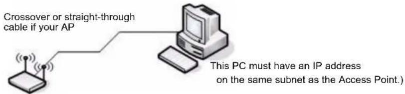
If you use this method, you will need to reconfigure the cabling for subsequent startup and deployment of the access point so that the access point is no longer connected directly to the PC but instead is connected to the LAN.
When you Telnet to the AP CLI the DLINK-WLAN-AP login: prompt appears.
Enter admin as the user name and admin as the password. After a successful login, the DLINK-WLAN-AP# prompt appears.
For information about how to disable the DHCP client on the AP or to set a static IP address, see "D-Link Access Point" on page 63 in the "Assigning the IP Address to Switches and Managed APs" section.
Changing the AP Password
For access to the AP, you need to provide the user name (admin), and a password. We recommend that you change the default AP password to make access to the device more secure.
To change the default password, log on to the AP and enter the following command:
set system password <password>
For example, the following command changes the password to test1234.
set system password test1234
The password you type appears in plain text. You are not asked to confirm the password after you enter it once.
Configuring 802.1X Authentication Information on the AP
On networks that use IEEE 802.1X port-based network access control, a supplicant (client) cannot gain access to the network until the 802.1X authenticator grants access. If your network uses 802.1X, you must configure 802.1X authentication information that the AP can supply to the authenticator.

Note: The access point supports MD5 authentication.
Table 5 shows the commands you can use to configure 802.1X supplicant information.
Table 5: IEEE 802.1X Supplicant Commands
| Action Command |
| View 802.1X supplicant settings get dot1x-supplicant |
| Enable 802.1X supplicant set dot1x-supplicant status up |
| Disable 802.1X supplicant set dot1x-supplicant status down |
| Set the 802.1X user name set dot1x-supplicant user |
| Set the 802.1s password set dot1x-supplicant password |
In the following example, the administrator enables the 802.1X supplicant and sets the user name to wlanAP and the password to test1234.
WLAN-AP# set dot1x-supplicant status up
WLAN-AP# set dot1x-supplicant user wlanAP
WLAN-AP# set dot1x-supplicant password test1234
WLAN-AP# get dot1x-supplicant
Property Value
status up
user wlanAP
Configuring AP-to-Switch Authentication Information
You can configure a pass phrase on the AP and on the switch so that only authenticated APs can associate with the switch. If you do enable AP authentication on the Unified Switch, you must connect to the access point CLI and configure a pass phrase. This pass phrase must be the same as the one you configure on the Unified Switch.
To configure the pass phrase on the AP, use the following command:
set managed-ap pass-phrase <phrase>
The pass phrase can be up to 32 alphanumeric characters.
For example, the following command sets the AP-to-Unified Switch authentication pass phrase to test1234.
WLAN-AP# set managed-ap pass-phrase test1234
For more information about AP-to-Unified Switch authentication and how to configure it on the switch, see "Configuring AP Authentication" on page 71.
Configuring VLAN Information on the Access Point
The management VLAN is VLAN 1 by default. This VLAN is also the default untagged VLAN. This means that all traffic, including management traffic, is untagged.
If you want to limit access to the management interface on the access point or if you already have a management VLAN configured on your network with a different VLAN ID, you can change the VLAN ID of the management VLAN on the access point from the AP CLI.
Table 6: AP VLAN Commands
Table 7
| Action Command | |
| View management interface information, including the VLAN ID | get management |
| Set the management VLAN ID | set management vlan-id <1-4094> |
| View untagged VLAN information get untagged-vlan | |
| Enable the untagged VLAN set untagged-vlan status up | |
| Disable the untagged VLAN set untagged-vlan status down | |
| Set the untagged VLAN ID | set untagged-vlan vlan-id <1-4094> |
DISCOVERING ACCESS POINTS AND PEER SWITCHES
The D-Link Unified Switch can discover, validate, authenticate, or monitor the following system devices:
- Peer Unified Switches
• D-Link Access Points - Wireless clients
- Rogue APs
- Rogue wireless clients.
This section describes the procedures you use to discover D-Link Access Points and other D-Link Unified Switches. For information about the discovery of wireless clients, see “” on page 142. For more information about discovering rogue devices, see “Monitoring Rogue and RF Scan Access Points” on page 138.
In order for the Unified Switch to discover other WLAN devices and establish communication with them, the devices must have their own IP address, must be able to find other WLAN devices, and must be compatible.
When the D-Link Unified Switch discovers and validates D-Link Access Points, the switch takes over the management of the AP. The default AP Profile settings are listed in Appendix A "D-Link Unified Access System Default Settings".
For information about how to change the AP Profile settings, see Chapter, "Configuring Access Point Settings" on page 77.
Understanding the Discovery Methods
The Unified Switch and AP have multiple ways of discovering each other. The following examples describe different ways the discovery can occur.
Example 1: L2 Discovery
In Figure 32, the AP and Unified Switch are directly connected. The devices are in the same layer 2 broadcast domain and use the default VLAN settings. After both devices acquire an IP address, either statically or through DHCP, the Unified Switch automatically discovers the AP through its broadcast of a L2 discovery message.
Figure 32: L2 Discovery Example
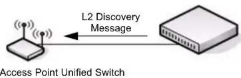
flowchart
graph LR
    A["Access Point Unified Switch"] --> B["L2 Discovery Message"]
    B --> C["Network Device"]
In this example, the administrator does not need to configure any discovery information on the AP or the Unified Switch. The L2 discovery works automatically when the devices are directly connected or connected by using a layer 2 bridge.
For more information about this discovery method, see "D-Link Wireless Device Discovery Protocol" on page 64.
Example 2: IP Address of AP Configured in the Switch
Figure 33 shows two access points. One AP is directly connected to the D-Link Unified Switch, and the other AP is connected via a L3 switch.
Figure 33: L3 Discovery Example 1
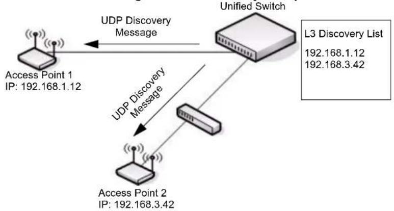
flowchart
graph TD
    A["Access Point 1\nIP: 192.168.1.12"] -->|UDP Discovery Message| B["Unified Switch"]
    C["Access Point 2\nIP: 192.168.3.42"] -->|UDP Discovery Message| B
    B --> D["L3 Discovery List\n192.168.1.12\n192.168.3.42"]
The administrator disables the L2 discovery method on the switch and adds the IP addresses of the APs to the L3 Discovery list on the switch. The Unified Switch sends UDP discovery messages to the IP addresses in its list. When the AP receives the messages and decides that it can connect to the switch, it initiates an SSL TCP connection to the switch.
For information about how to configure this discovery method, see "Configuring IP Addresses of Peers and APs in the Switch" on page 66.
Example 3: IP Address of Switch Configured in the AP
In this example, the administrator connects to the access point CLI and statically configures the IP addresses of two D-Link Unified Switches that are allowed to manage the AP.
Figure 34: L3 Discovery Example 2
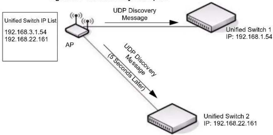
flowchart
graph TD
    A["AP"] -->|UDP Discovery Message (5 Seconds Later)| B["Unified Switch 1"]
    B --> C["Unified Switch 2"]
    A -->|Unified Switch IP List 192.168.3.1.54\n192.168.22.161| A
    B -->|Unified Switch IP: 192.168.1.54| B
The AP sends a UDP discovery message to the first IP address configured in its list. When the switch receives the message, it verifies that the vendor ID on the AP is valid, there is no existing SSL TCP connection to the access point, and the maximum number of managed APs hasn't been reached. If all these conditions are met then the switch sends an invitation message to the AP to start the SSL TCP connection.
If the AP does not receive an invitation from the first Unified Switch configured in its list, it sends a UDP discovery message to the second Unified Switch configured in the list five seconds after sending the message to the first Unified Switch.
When an IP address of a Unified Switch is configured on the AP, the AP only associates with that switch even if other switches discover the AP by using other mechanisms.
For more information about how to configure this discovery method, see "Setting the Switch IP Address in the D-Link Access Point" on page 68.
Example 4: DHCP Option
In this example, the administrator has configured the IP address of the Unified Switch as an option in the DHCP response to the DHCP request that the AP sends the DHCP server.
Figure 35: DHCP Option Example
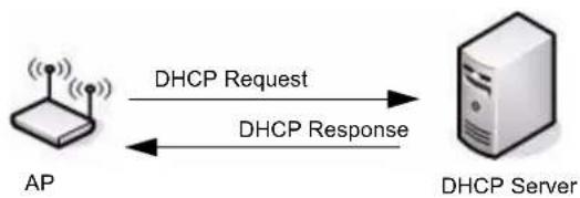
flowchart
graph LR
    A["AP"] -->|DHCP Request| B["DHCP Server"]
    B -->|DHCP Response| A
The AP can learn up to four Unified Switch IP addresses or DNS names through DHCP option 43 in the DHCP response.
This discovery method only works if you configure the DHCP option before the AP receives its network information from the DHCP server.
For information about how to configure option 43 with the IP address of one or more Unified Switch, see “Setting the Switch Information in the DHCP Option” on page 69.
Discovery and Peer Switches
When multiple peer switches are present in the network, you can control which switch or switches are allowed to discover a particular AP by the discovery method you use.
If you want to make sure that an AP is discovered by one specific switch, use one of the following methods:
- Disable L2 Discovery on all switches and configure the IP address of the AP in only one Unified Switch.
- Configure the IP address of one Unified Switch in the AP.
- Configure the DHCP option 43 with the IP address of only one Unified Switch.
An alternative approach is to configure the RADIUS server to return a switch IP address during AP MAC address checking in the AP authentication process. For information about how to configure the RADIUS server to return a switch IP address, see Appendix Appendix B:, "Configuring the External RADIUS Server" on page 207.
If the RADIUS server indicates that the AP is a valid managed AP and returns an IP address of a switch that is not the same as this switch, then the switch sends a "re-link" message to the access point with the IP address of the Unified Switch to which the AP should be talking to. When the AP gets the re-link message it modifies or sets the Unified Switch IP address, breaks the TCP connection with the current switch and starts a new discovery process.
You can configure the D-Link Unified Access System so that each AP is allowed to be managed by any of the four switches in a peer group. If the Unified Switch that manages an AP goes down, one of the backup switches takes over the management responsibilities.
To use one or more peer switches as a backup for an AP, use one of the following discovery methods:
- If the AP and any of the peer switches are in the same L2 broadcast domain, L2 Discovery is enabled, and all the devices use the default VLAN settings, a peer switch will automatically discover the AP if the primary Unified Switch becomes unavailable.
- Configure the IP address of the AP in up to four switches.
- Connect to the access point CLI and configure the IP address of up to four switches.
- Configure the DHCP option 43 with the IP address of up to four switches in a peer group.
Assigning the IP Address to Switches and Managed APs
D-Link Unified Switches communicate with each other and with D-Link Access Points by using the IP protocol, so each device must have a valid IP address.
D-Link Unified Switch with Routing Disabled
If routing is disabled on the D-Link Unified Switch, it uses the network interface address of the switch that you configured during the initial setup process.

Note: If you change the IP address of the network interface, the wireless function on the switch automatically disables and re-enables. If you used DHCP for the IP address assignment, make sure the lease does not expire.
D-Link Unified Switch with Routing Enabled
If the routing mode is enabled on the D-Link Unified Switch, you must create a loopback or routing interface on the switch. Peer switches and APs use the IP Address of the lowest loopback interface index to identify and communicate with the switch. If you do not define a loopback interface, the wireless function uses the lowest index routing interface.
If routing is enabled, we strongly recommend that you define a loopback interface on the switch. By creating a loopback interface, you can control which routing interface the wireless function uses for its IP address when multiple routing interfaces exist. This can avoid discovery problems for the discovery modes that use the IP address of the Unified Switch. With the loopback interface, the IP address of the wireless function is always the same.

Note: In this context, the loopback interface does not refer to the loopback interface with the 127.0.0.1 IP address. When you configure a loopback interface for the wireless interface on the switch, it is essentially a permanent logical interface and cannot have an IP address of 127.0.0.1. You must create a dedicated subnet for the loopback interface, and other devices on the network must be able to contact the IP address of the loopback interface.
The advantage of defining a loopback interface is that the interface never goes down. The disadvantage is that network configuration is more complex because the loopback interface is located on its own subnet and the rest of the network must know how to get to the subnet.
The network must have routes between the Unified Switch and the APs you want it to manage. The APs must be able to ping the IP address assigned to the wireless interface on the Unified Switch. You configure static routes on the switch through the configuration pages under LAN > L3 Features > Router.
The following procedures show an example of how to enable routing and configure a IP address on a routing or loopback interface by using the CLI:
1 Log on to the CLI and switch to Global Config mode:
(switch-prompt)
User: admin
Password:
(switch-prompt) >enable
Password:
(switch-prompt) #config
(switch-prompt) (Config)#
2 Enable routing.
(switch-prompt) (Config)#ip routing
3 Change to Interface Config mode for loopback interface 0, and assign an IP address and subnet mask.
(switch-prompt) (Config)#interface loopback 0
(switch-prompt) (Interface loopback 0)#ip address 10.1.1.1 255.255.0.0
4 [Optional] Change to Interface Config mode for slot 0, port 2, assign an IP address, and enable routing on the interface.
(switch-prompt) (Config)#interface 0/2
(switch-prompt) (Interface 0/2)#ip address 192.168.1.24 255.255.255.0
(switch-prompt) (Interface 0/2)#routing
You can also use the Web interface or SNMP to enable routing and configure an IP address. The following shows the procedures to enable routing and configure an IP address on the switch by using the Web interface.

Note: Routing is available under the LAN tab on the navigation menu.
1 Log on to the Web interface and click L3 Features > IP > Interface Configuration to access the IP Configuration page.
2 From the Routing Mode menu, choose Enable, and then click Submit.
3 To create a loopback interface, click Routing > Loopback > Configuration.
4 From the Loopback menu, choose Create, and then click Submit
5 Enter an IPv4 address and subnet mask in the appropriate fields, and then click Submit.
6 To create a routing interface and assign an IP address, click Routing > IP > Interface Configuration, and select the interface to configure from the Slot/Port menu.
7 Enter an IP address and subnet mask in the appropriate fields, choose Enable from the Routing Mode menu, and click Submit.
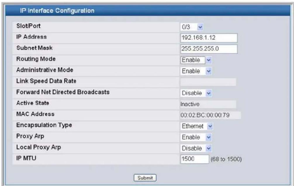
D-Link Access Point
On the D-Link Access Points, the default IP address is 10.90.90.91/8, and DHCP is enabled by default. If you do not have a DHCP server on the network, the AP retains its default IP address until you assign a static IP address.
You can connect to the AP CLI from a host on the 10.0.0.0/8 network by telnetting to the AP's default IP address.
To set a static IP address on the AP, use the following procedures:
1 Log on to the D-Link Access Point.
For information about how to log on to the AP, see "Logging on to the AP" on page 55.
2 Enter get management to view information about the AP's management interface.
3 Disable the DHCP client on the AP so that it does not broadcast DHCP requests. set management dhcp-status down
4 To set the static IP address, enter the following command:
set management static-ip <ipaddress> static-mask <subnet_mask>
For example:
set management static-ip 192.168.22.133 static-mask 255.255.255.0
5 To set the default gateway, enter the following command:
set static-ip-route gateway <gateway_ip> mask <subnet>
For example,
set static-ip-route gateway 102.168.22.1 mask 255.255.255.0
6 From the CLI, enter save-running to save the configuration to memory.
You can use the Unified Switch as a DHCP server. If you plan to use the Unified Switch as the DHCP server that responds to DHCP requests from the AP, see "Setting the Switch Information in the DHCP Option" on page 69.
Enabling the AP and Peer Switch Discovery
The D-Link Unified Switch can discover peer Unified Switches and D-Link Access Points regardless of whether these devices are connected to each other, located in the same Layer 2 broadcast domain, or attached to different IP subnets.
You can enable discovery between the D-Link Access Point and D-Link Unified Switch by using one of following four mechanisms:
- Use VLANs to broadcast the D-Link Wireless Device Discovery Protocol.
- Connect to the access point CLI and manually add the IP address of the switch.
- Configure a DHCP server to include the switch IP address in the DHCP response to the AP DHCP client request.
- Manually add the IP address of the AP to the switch. Multiple peer switches might find the same access point. The first association always takes precedence. The AP does not change its association unless the connectivity to the current Unified Switch fails or the switch tells the AP to disassociate and associate with another switch.
The following sections describe each discovery mechanism.
D-Link Wireless Device Discovery Protocol
The Wireless Device Discovery Protocol is part of the D-Link Wireless AP Protocol (DWAPP). It is a good discovery method to use if D-Link Unified Switches and D-Link Access Points are located in the same Layer 2 multicast domain. The D-Link Unified Switch periodically sends a multicast packet containing the discovery message on each VLAN enabled for discovery. You can enable the discovery protocol on up to 16 VLANs.
By default, VLAN 1 is enabled on the AP, and VLAN 1 is enabled for discovery on the Unified Switch. If the switch and AP are in the same Layer 2 multicast domain, you might not need to take any action to enable AP-to-Switch discovery.
If the switch has discovered a new AP by using L2 discovery and the MAC address of the AP is not in the Valid AP database, the AP appears in the list on the Monitoring > Access Point > Authentication Failed Access Points page. To view AP authentication failures from the CLI, enter show wireless ap failure status in Privileged EXEC mode.
The APs process the discovery message only when it comes in on the management VLAN. The APs do not forward the L2 discovery messages onto the wireless media.
Use the following procedures to add a VLAN to the discovery list by using the Web interface:
1 Use a browser to log on to the D-Link Unified Switch.
2 From the Navigation menu, click Administration > Basic Setup, then select the Discovery tab.
3 Make sure the box for L2/VLAN Discovery is selected and add the management VLAN ID of an AP or peer switch to the VLAN (1-4094) field.
4 Click Add to add the VLAN to the list.
5 Click Submit to apply the changes.
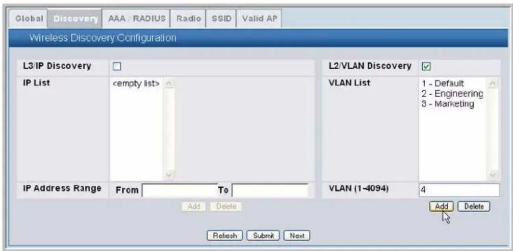
From the Unified Switch, you can check the discovery status. To view information about whether the switch discovered the AP, click the Monitoring > Access Points > Managed Access Points tab. If you have not added the MAC address of the AP to the local or RADIUS Valid AP database, the AP appears in the Monitoring > Access Point > Authentication Failed Access Points list, and the failure type is listed as No Database Entry. For more information about AP validation, see "Authenticating and Validating Access Points" on page 70.
The following example shows how to add a VLAN to the list by using the CLI.
1 From a Telnet, SSH, or serial connection, log on to the D-Link Unified Switch and enter the Wireless Configuration mode.
(switch-prompt) >enable
Password:
(switch-prompt) #config
(switch-prompt) (Config)#wireless
2 Add a VLAN to the discovery list:
(switch-prompt) (Config-wireless)#discovery vlan-list 4
3 Enter CTRL + Z to return to Privileged EXEC mode.
4 Save the changes to the configuration file:
(switch-prompt) #write
This operation may take a few minutes. Management interfaces will not be available during this time.
Are you sure you want to save? (y/n) y
Configuration Saved!
To check the managed status from the Unified Switch CLI, enter the following command:
(switch-prompt) #show wireless ap status
Configuring IP Addresses of Peers and APs in the Switch
You can configure up to 256 IP addresses for potential peer switches and APs in the D-Link Unified Switch. The switch sends association invitations to all IP addresses in this list. If the device accepts the invitation and is successfully validated by the switch, the switch and the AP or peer switch are associated.
This discovery method mechanism is useful for peer switch discovery and AP discovery when the devices are in different IP subnets. In fact, for a switch to recognize a peer that is not on the same subnet, you must configure the IP addresses of each switch in the peer's L3 discovery list.

Note: The list of IP addresses is separate and independent from the list of valid managed APs. Devices discovered through this list might not be valid APs or switches.

Note: If an AP has already been discovered through another method, the Unified Switch will not poll the IP address of the AP.
Table 8: L3/IP Discovery
| Field Description | |
| L3/IP Discovery | This check box is used to enable or disable IP-based discovery of access points and peer Unified Switches. When checked, IP polling is enabled and the switch will periodically poll each address in the configured IP List. By default, L3/IP Discovery is enabled. |
| IP List | The list of IP addresses configured for discovery, to remove entries from the list select one or more entries and press the delete button. There are no default entries, the maximum number of entries supported is 256. |
| IP Address Range | This text field is used to add a range of IP address entries to the IP List. Enter the IP address at the start of the address range in theFromfield, and enter the IP address at the end of the range in theTofield, then clickAdd. All IP addresses in the range are added to the IP List.Once all desired entries are added, clickSubmitto save the list in the running configuration.Note: To add a single IP address, enter the address in theFromfield and leave theTofield blank, then clickAdd. |
To view the IP address of the AP, log on to the AP as described in "Logging on to the AP" on page 55 and enter the get management command.
Use the following procedures to add the IP address of a peer switch or AP to the discovery list by using the Web interface:
1 Use a browser to log on to the D-Link Unified Switch.
2 From the Navigation menu, click Administration > Basic Setup, then select the Discovery tab.
3 Clear the check box for L2/IP Discovery to prevent the switch from sending L2 Discovery messages.
4 Make sure the check box for L3/IP Discovery is selected and add the range of peer switch or D-Link Access Point IP addresses in the From and To fields next to IP Address Range.
If the IP addresses are non-contiguous or if you only want to add one IP address, enter the the address in the From field,
and leave the To field blank.
5 Click Add to add the IP addresses to the list.
6 Click Submit to save the lists in the running configuration.
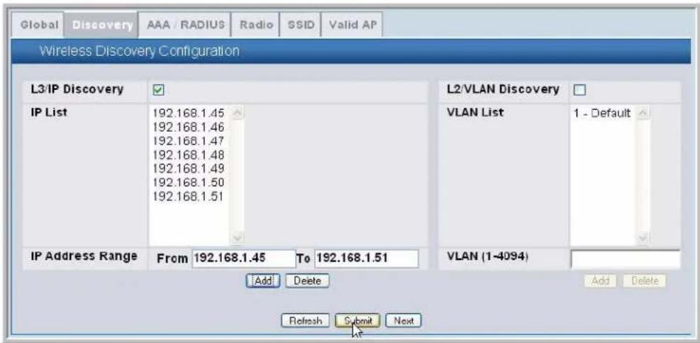
Use the buttons at the bottom of the page to perform the following tasks:
- Click Refresh to update the screen with the most current information.
- Click Next to navigate to the Wireless Default AAA/RADIUS Configuration page.
To view information about whether the switch successfully polled the IP address you entered, click the Monitoring > Global > IP Discovery tab.
The following example shows how to add an address to the L3 Discovery list by using the CLI.
1 From a Telnet, SSH, or serial connection, log on to the D-Link Unified Switch and enter the Wireless Configuration mode.
(switch-prompt) >enable
Password:
(switch-prompt) #config
(switch-prompt) (Config)#wireless
2 Add the IP address of a peer switch or AP to the discovery list:
(switch-prompt) (Config-wireless)#discovery ip-list 192.168.6.211
From the CLI, you can only add one IP address at a time.
3 Enter CTRL + Z to return to Privileged EXEC mode.
4 Save the changes to the configuration file:
(switch-prompt) #write
This operation may take a few minutes. Management interfaces will not be available during this time.
Are you sure you want to save? (y/n) y
Configuration Saved!
To check the managed AP status from the Unified Switch CLI, enter the following command:
(switch-prompt) #show wireless ap status
Setting the Switch IP Address in the D-Link Access Point
You can connect to the D-Link Access Point CLI and statically set the IP address or DNS name of the D-Link Unified Switch. You can configure up to four D-Link Unified Switches for AP association, but you can only use one switch to manage the AP. The other three switches are backup or alternate switches.
Once you configure the AP with the IP addresses or DNS names of switches, the AP will only associate with those switches. Even if other switches discover the AP by using other mechanisms, the AP only accepts associations from the Unified Switches you configure. If you change the IP address of the switch that manages the AP, you must use a secondary switch to manage the AP. You can connect directly to the AP CLI and configure the IP address of the switch that will manage the AP.
If you know the IP address of the D-Link Access Point, you can Telnet to the CLI. The default IP address of the AP is 10.90.90.91 with a default subnet mask of 255.0.0.0.

Note: For this method to work, the AP must be able to find a route to the Unified Switch.
1 Log on to the D-Link Access Point.
For information about how to log on to the AP, see "Logging on to the AP" on page 55.
2 Enter the IP address of up to four switches that are permitted to manage the AP.
For example, to enter a Unified Switch with an IP address of 192.168.66.202 and a Unified Switch with an IP address of 192.168.19.242, use the following commands:
WLAN-AP# set managed-ap switch-address-1 192.168.66.202
WLAN-AP# set managed-ap switch-address-2 192.168.19.242
3 Use the get managed-ap command to verify that the information you entered is correct.
WLAN-AP# get managed-ap
Property Value
mode up
ap-state down
switch-address-1 192.168.66.202
switch-address-2 192.168.19.242
switch-address-3
switch-address-4
dhcp-switch-address-1
dhcp-switch-address-2
dhcp-switch-address-3
dhcp-switch-address-4
managed-mode-watchdog 0
From the Unified Switch, you can check the discovery status. To view information about whether the switch discovered the AP, click the Monitoring > Access Points > Managed Access Points tab. It might take several minutes for the AP to discover the switch.

Note: If you have not added the MAC address of the AP to the local or RADIUS Valid AP database, the AP appears in the Monitoring > Access Point > Authentication Failed Access Points list, and the failure type is No Database Entry. For more information about AP validation, see "Authenticating and Validating Access Points" on page 70.
To check the Managed AP status from the Unified Switch CLI, enter the following command:
(switch-prompt) #show wireless ap status
Setting the Switch Information in the DHCP Option
Instead of statically configuring the Unified Switch IP address in the AP, you can configure the DHCP server on your network to pass the IP addresses of up to four D-Link Unified Switches to the access point in DHCP option 43. If you configured a static IP address in the D-Link Access Point, the AP ignores DHCP option 43.
The procedures to add the DHCP option to the DHCP server depend on the type of DHCP server you use on your network. If you use a Microsoft Windows 2000 or Microsoft Windows 2003 DHCP Server, you configure the scope you use with the access points with DHCP Option 43, as the following procedures describe.
1 From the DHCP manager, right-click the applicable scope and select Configure Options...
![DHCP File Action View Help DHCP M7nc-wireless.wlan.com [192.168.30.2] Scope [20.0.0.0] murali Scope [20.1.0.0] murali1 Scope [20.2.0.0] murali2 Scope [20.3.0.0] murali3 Address Pool Address Leases Reservations Scope Options Scope [192.168.30.0] WVLAN-10 Address Pool Address Leases Reservations Configure Options... View Refresh Export List... Help Scope Options Option Name Vendor 003 Router Standard 006 DNS Servers Standard 015 DNS Domain Name Standard 044 WINS/NBNS Servers Standard 046 WINS/NBT Node Type Standard Configure scope options](/content/2026/05/943242/images/85d61ef88e486492af86aa22709482f61905cfb6d06d2b3916ea16ea02fe3a53.jpg)
2 From the Available Options list, scroll to Option 43 and select the 043 Vendor Specific Info check box.
3 Enter the Option 43 data into the Data Entry field.
The format for DHCP option 43 values are defined by RFC 2132. To enter an IP address of 192.168.1.10 into the Binary column, you enter the data type code (01) and the address length (04), followed by the IP address in hexadecimal format. You repeat the data type and address length codes for each address you enter.
For example, to add the four switch IP addresses 192.168.1.10, 192.168.2.10, 192.168.3.10, and 192.168.4.16 to Option 43, you enter the following hexadecimal numbers into the Data Entry field:
01 04 0C A8 01 0A 01 04 0C A8 02 0A 01 04 0C A8 03 0A 01 04 0C A8 04 10
The following image shows the four IP addresses entered into the Data Entry field on the Windows DHCP server.
![DHCP File Action View Help DHCP M7nc-wireless.wlan.com [192.168.30.2] Scope Options General | Advanced | Available Options Description □ 041 NIS Servers Addresses c □ 042 NTP Servers Addresses c ✓ 043 Vendor Specific Info Embedded ✓ 044 WINS/NBNS Servers NBNS Addr Data entry Data: Binary: ASCII: 0000 01 04 C0 A8 01 0A 01 04 A ... 0008 C0 A8 02 0A 01 04 C0 A8 A ... 0010 03 0A 01 04 C0 A8 04 10 ...A... 0018 OK Cancel Apply](/content/2026/05/943242/images/08b2a5c050a1e71594e8edc99b73648e1ce916bfb55c924578bf6f6bcffec450.jpg)
4 Click OK.
The following figure shows a scope with Option 43 configured.
![DHCP File Action View Help DHCP M7nc-wireless.wlan.com [192.168.30.2] Scope [20.0.0.0] murali Scope [20.1.0.0] murali1 Scope [20.2.0.0] murali2 Scope [20.3.0.0] murali3 Address Pool Address Leases Reservations Scope Options Scope [192.168.30.0] WVLAN-10 Address Pool Address Leases Reservations Scope Options Scope [192.168.31.0] WVLAN-20 Scope [192.168.32.0] WVLAN-30 Server Options Scope Options Option Name Vendor Value Class 003 Router Standard 192.168.30.1 None 006 DNS Servers Standard 192.168.30.2 None 015 DNS Domain Name Standard wlan.com None 043 Vendor Specific Info Standard 01-04-c0-s0-01-0s-01-04-c0-s0-02-0s... 044 WINS/NBNS Servers Standard 192.168.30.2 None 046 WINS/NBT Node Type Standard 0x8 None Scope with Configured Option 43 Information](/content/2026/05/943242/images/8c378bcb5ece59ca089d5718a252f143843f636e92d27d855d3f54d191027ead.jpg)
AUTHENTICATING AND VALIDATING ACCESS POINTS
For a D-Link Unified Switch to manage an AP, you must add the MAC address of the AP to the local or external RADIUS database. When the switch discovers an AP that is not managed by another Unified Switch, it looks up the MAC address of the AP in the local or RADIUS Valid AP database. If it finds the MAC address in the database, the switch validates the AP
and assumes management. If you have not added the MAC address of the AP to the database, the AP appears in the Authentication Failed Access Points list, and the failure type is No Database Entry.
Optionally, you can require that the AP is authenticated before the Unified Switch manages it. You can add authentication information about the AP when you add its MAC address to the local or RADIUS database. If you enable authentication, it takes place immediately after the switch validates the AP.

Note: When a switch successfully validates an AP, it sends an AP Profile to the access point. The AP Profile contains all of the access point configuration information, such as the radio, security, and SSID settings. You can configure all of the AP settings before the switch validates an AP. For information about configuring the default AP profile, see "Configuring Access Point Settings" on page 77.
Configuring AP Authentication
Unless access to the wired network is secured with IEEE 802.1X authentication or another security mechanism, the AP should always use authentication so that Rogue APs do not automatically associate with the switch.
If you require the AP to authenticate itself to the switch, you must perform the following three steps:
1 Enable AP authentication on the switch, which is described in this section.
2 Connect to the access point CLI and configure a pass phrase as described in "Preparing the Access Points" on page 55.
3 Enter the pass phrase in the Valid AP database.
To enter a pass phrase in the local database, see "Using the Local Database for AP Validation" on page 72. To enter a pass phrase in the RADIUS database, see "Using the RADIUS Database for AP Validation" on page 73.
To enable AP authentication on the Unified Switch, click Administration > Basic Setup. From the Global tab, check the AP Authentication box, then click Submit to apply your changes.
Figure 36: Requiring AP Authentication
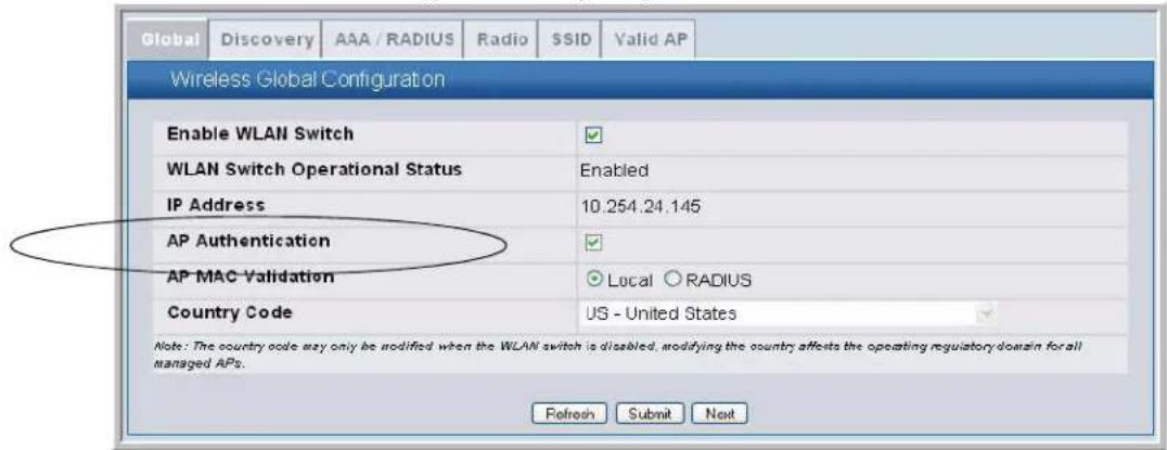
To enable AP authentication from the CLI, access Wireless Config mode and enable authentication:
(switch-prompt) >enable
Password:
(switch-prompt) #config
(switch-prompt) (Config)#wireless
(switch-prompt) (Config-wireless)#ap authentication
Using the Local Database for AP Validation
To use the local Valid AP database, set the AP MAC Validation to local, add APs to the database, and configure the settings for the APs in the database. All of the configuration takes place on the switch.
To set up the local database for AP MAC Validation, use the following steps:
1 From the Administration > Basic Setup > Global page, make sure AP MAC Validation is set to Local, which is the default.
2 Click Submit if you made any changes.
3 Click the Valid AP tab.
4 In the MAC Address field, enter the MAC address of the AP to validate, and enter the physical location of the AP in the second field, then click Add.
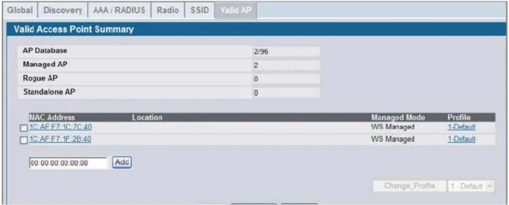

If the switch has already discovered the AP, the MAC address of the AP appears on the Monitoring > Access Points > Managed Access Points page or on the Monitoring > Access Point > Authentication Failed Access Points page. To view the MAC address of discovered APs from the CLI, enter show wireless ap status or show wireless ap failure status in Privileged EXEC mode.
After you add the AP, additional fields appear so you can provide configuration information about the AP, including a passphrase for AP authentication.
5 If you selected the AP Authentication check box on the Wireless Global Configuration page, select the Apply check box and enter an authentication password for the AP.
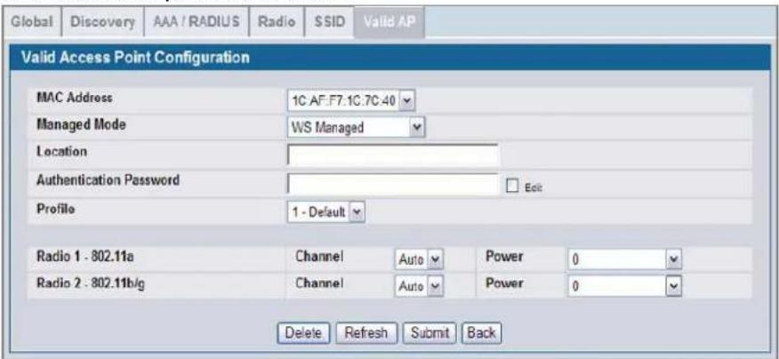
The password must match the pass phrase that you configured on the AP. The length of the password can be 8-63
alphanumeric characters, but for good security, you should enter at least 24 characters.
6 Use the default settings or configure other information about the AP, such as the channel the AP uses and the strength of the power transmission.
For more information about the fields on the Valid Access Point Configuration page and how to configure valid APs, see "Configuring Valid Access Point Settings" on page 101.
7 Click Submit to apply your changes to the running configuration.
The following example shows how to configure the local database by using the CLI:
1 Log on to the switch and enter Wireless Config Mode.
(switch-prompt) >enable
Password:
(switch-prompt) #config
(switch-prompt) (Config)#wireless
2 Set the local database as the validation method.
(switch-prompt) (Config-wireless)#ap validation local
3 Enter the MAC address of the AP to add to the database and configure a password:
(switch-prompt) (Config-wireless)#ap database 00:02:BC:00:14:40
4 If you require AP-to-switch authentication, enter the pass phrase for the AP
(switch-prompt) (Config-ap)#password
Enter password (8 - 63 characters):**************************
Re-enter password:**************************
For information about configuring additional database parameters for an AP by using the CLI, see the D-Link CLI Command Reference.
Using the RADIUS Database for AP Validation
To use a RADIUS server to validate the AP, you must configure settings on both the Unified Switch and the RADIUS server. From the switch, set the AP Validation to RADIUS and configure information about the RADIUS server, such as its IP address. From the RADIUS server, configure information about the Valid APs, including the pass phrase for AP authentication. For information about the parameters to configure on the RADIUS server, see Appendix Appendix B:, "Configuring the External RADIUS Server" on page 207.
When you enable RADIUS as the validation method, the local Valid AP database is not used. The Valid AP database is only used for local authentication and validation.
To use a RADIUS server for the Valid AP database, use the following procedures:
1 From the Administration > Basic Setup > Global page, set AP Validation to RADIUS.
2 Click Submit to apply the changes.
3 From the LAN menu, click Security > RADIUS > RADIUS Authentication Server Configuration.
The RADIUS settings in the AAA/RADIUS tab in the Wireless Global Configuration Basic Setup are applied to access points that use the default AP Profile - and not to the switch. If you require a RADIUS server to authenticate wireless clients before they can associate with an AP, you configure the settings in the AAA/RADIUS tab as described in "Configuring AAA and RADIUS Settings" on page 79.
4 Enter the IP address of the RADIUS server to use for the valid AP database and click Submit.
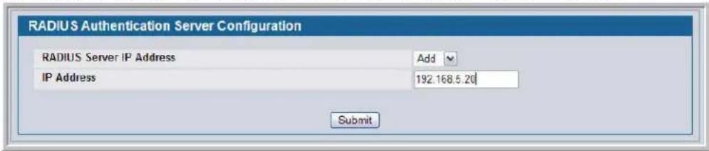
Additional fields appear.
5 Configure information that the Unified Switch must use to contact the RADIUS server on your network, such as the shared secret.
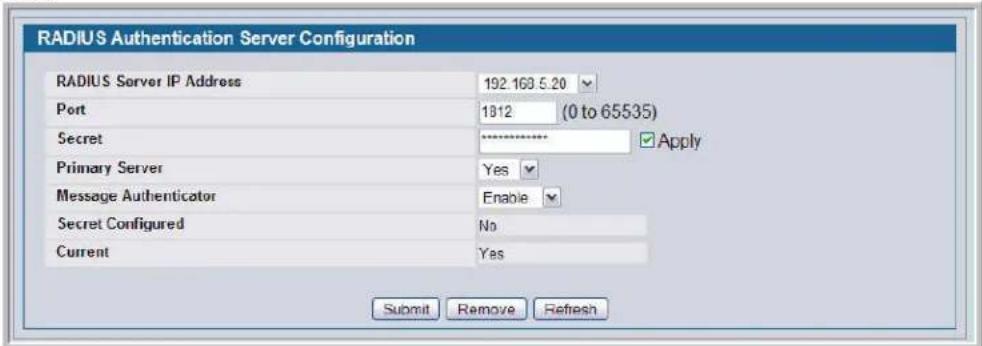
6 Click Submit to apply your changes.
The following example shows how to configure RADIUS authentication by using the CLI:
1 Enter the Wireless Config mode.
(switch-prompt) >enable
Password:
(switch-prompt) #config
(switch-prompt) (Config)#wireless
2 Set the RADIUS server as the validation method.
(switch-prompt) (Config-wireless)#ap validation radius
3 Exit to Global Config Mode and configure the RADIUS settings.
In the following command example, the RADIUS server IP address is 192.168.2.2.
(switch-prompt) (Config-wireless)#exit
(switch-prompt) (Config)#radius server host auth 192.168.2.2
(switch-prompt) (Config)#radius server key auth 192.168.2.2
Enter secret (16 characters max):**************************
Re-enter secret:***************************
For information about configuring additional RADIUS parameters by using the CLI, see the D-Link CLI Command Reference.
Managing Failed or Rogue APs
If an AP attempts to contact a switch but the authentication fails or if the MAC address of an AP is not in the Valid AP database, AP Validation fails and the AP appears in the list on the Authentication Failed Access Points page. If the switch
Software User Manual D-Link Unified Access System
02/15/2011
learns about an AP that is not in the database, and the AP has not tried to discover the switch, the AP appears in the list on the Rogue/RF Scan Access page.
You can add the AP to the local Valid AP database from the list on the Authentication Failed Access Points page or the Rogue/RF Scan Access page.
To add an AP from the Authentication Failed Access Points page or the Rogue/RF Scan Access page to the local Valid AP database, use the following procedures:
1 Access either the Authentication Failed Access Points page or the Rogue/RF Scan Access page from the by clicking Monitoring > Access Point folder.
2 Select the check box associated with the AP and click Manage.
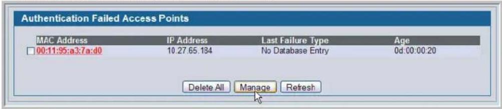

Note: You cannot add an AP to the RADIUS database from the AP authentication failure page. If you use a RADIUS server for AP Validation, you must enter the AP information into the RADIUS database.
3 The Valid Access Point Configuration page for the added AP is displayed.
Configure the appropriate fields, such as Location and Profile, and then click Submit.
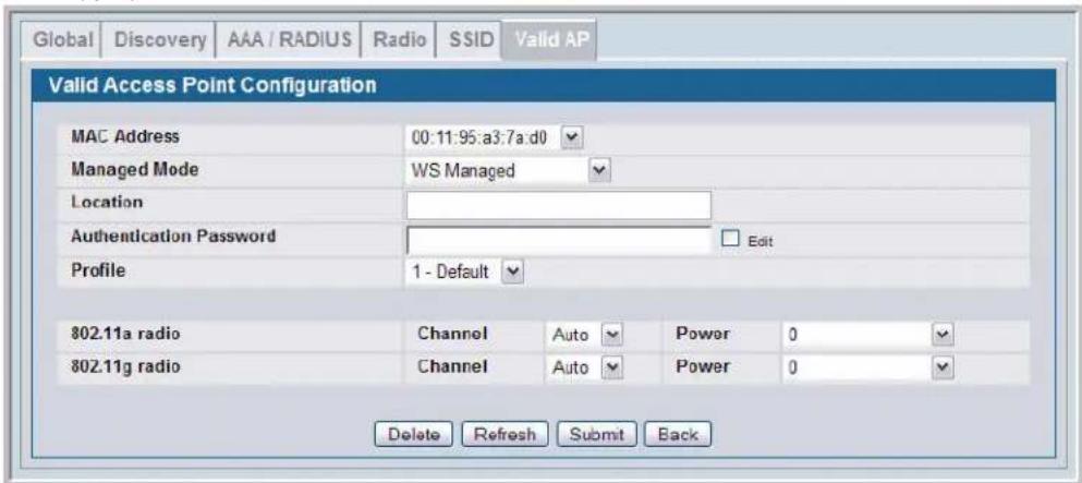
The AP is added to the Valid AP database, and its MAC address appears in the list on the Administration > Basic Setup > Valid AP page.

Note: If you select multiple APs to manage, the Web interface displays the selected APs in the MAC Address field one by one after you submit a configured AP entry.
To view the list of failed APs by using the CLI, use the show wireless ap failure status command in Privileged EXEC mode. To view the list of APs detected through the RF scan, use the show wireless ap rfscan status command.
To add a failed or rogue AP to the local Valid AP database, use the procedures described in "Using the Local Database for AP Validation" on page 72.
Section 6: Configuring Access Point Settings
After you validate a D-Link Access Point that associates with a switch, the switch assumes management functions for the AP. You can configure all of the AP settings directly from the switch before or after you validate the AP. The D-Link Unified Access System utilizes the D-Link Wireless AP Protocol (DWAPP) for the switch to discover, configure, manage, and monitor the APs. This chapter describes the AP settings and how to manage them by using the D-Link Unified Switch.
This chapter contains the following sections:
- "AP Profiles, Networks, and the Local Database"
- "Configuring AAA and RADIUS Settings"
- "Configuring Wireless Radio Settings"
- "Configuring SSID Settings"
- "Configuring Valid Access Point Settings"
For information about the commands you use to configure access point settings by using the CLI, refer to the D-Link CLI
Command Reference.

Note: Changing some access point settings might cause the AP to stop and restart system processes. If this happens, wireless clients will temporarily lose connectivity. We recommend that you change access point settings when WLAN traffic is low.
AP Profiles, Networks, and the Local Database
This section provides an overview of the access point profiles, wireless networks, and the local access point database that you configure on the D-Link Unified Switch.
Access Point Profiles
You manage the configuration of D-Link Access Points through the use of configuration profiles. A profile is like a configuration template that you can apply to one or more APs. The D-Link Unified Switch allows you to create multiple configuration profiles for access points. When you validate an AP, you can specify which profile the AP receives.
You can define many AP profiles on the Unified Switch, but each access point can only have one profile at a time. You can use the same profile for multiple APs, or you can create a unique profile to assign each AP that the switch manages. An existing profile and all of its configurations may be copied to another profile or used to create a new profile. Each configuration profile can have unique settings for the following access point features:
• RADIUS server settings
- MAC authentication list
• Radio interface and RF configuration
- QOS Configuration
• Virtual Access Point (VAP) Configuration
When you modify and apply a profile, the switch applies the changes to the APs it manages that use the modified profile.

Note: The switch only applies the changes to the APs after you explicitly apply the profile on the Advanced Configuration >AP Profile page or use the ap profile apply command.
Until you apply the updated profile to the APs, the APs continue to operate with the original AP profile settings. If you assign a new profile to the AP in the Valid AP database, you must reset the AP.
All of the AP settings that you configure from the tabs on the Basic Setup page are for the default AP profile. When you make changes to these settings, the settings affect all APs that use the default profile.
All of the fields that you configure for the default profile are also available for profiles that you create. For information about how to create a new profile and assign it to an AP, see “Creating, Configuring, and Managing AP Profiles” on page 153.
Networks
In general, a wireless client connects to an access point by choosing a network (identified by the SSID) from a list of available wireless networks. You configure these wireless networks, including their associated SSID, on the D-Link Unified Switch.
You manage the networks available on the WLAN by modifying or adding network configurations, which include settings for the SSID, VLAN ID, security, and tunneling parameters. You can associate a network with a Virtual APs (VAPs) within an AP configuration profile.
By default, the switch has 8 networks, and each network is associated with one of the 8 VAPs on each radio. You can modify (but not delete) the default network configurations and add new network configurations. The first network is configured with a default SSID "Guest Network," and the other networks have default SSIDs assigned based on the Network ID. All the default networks are configured with open authentication and assigned to the default VLAN 1. The default VLAN is used if RADIUS-based authentication is not configured for the network or the RADIUS server does not return a VLAN for a specific client.
Click WLAN > Administration > Advanced Configuration > Networks to see the Wireless Network Summary page. Click any network SSID to access the Wireless Network Configuration page.
Local Access Point Database
In order for a Unified Switch to manage an access point, you must add the physical MAC address of the AP to the Valid AP database. The Valid AP database can reside locally on the switch or externally on a RADIUS server. When an AP is discovered, the switch verifies the AP's MAC address according to the validation mode (local or RADIUS) as long as the AP is enabled for Managed Mode and has been authentication (if required). Once the AP is verified, it becomes managed by the switch.
If an AP is discovered and its MAC address is not found in the Valid AP database or the AP fails to authenticate, the switch adds an entry to the AP failure list. If you use the local Valid AP database, you can add the failed AP to the Valid AP database directly from the AP Authentication Failures page.
The Valid AP database stores additional information about the AP along with its MAC address such as the AP mode, local authentication password, and the AP profile that the access point uses. You can also manually set the channel and RF signal transmit power level for an individual AP, which overrides the channel and power settings in the AP profile.
Configuring AAA and RADIUS Settings
In the D-Link Unified Access System, you can use a RADIUS server for the following functions:
- Management of client-to-AP authentication and accounting
- Management of AP-to-Switch authentication and accounting
- Database for AP settings
The information in this section applies to the client-to-AP authentication and accounting management. For information about AP-to-switch management, see "Using the RADIUS Database for AP Validation" on page 73. For information about how to set AP database settings in the RADIUS server, see Appendix B "Configuring the External RADIUS Server".
The RADIUS server that you configure from the Administration > Basic Setup > AAA/RADIUS tab is the RADIUS server for the default AP profile. For each network, you can configure a unique RADIUS server or use the default RADIUS server.
When you use a RADIUS server for wireless client-to-AP communications, such as when clients use WPA Enterprise or WEP IEEE 802.1X security to connect to the AP, the AP is the RADIUS client and communicates with the RADIUS server. The Unified Switch does not tunnel packets between the AP and RADIUS server. This means that you must configure the AP as a client in the RADIUS server. For information about how configure RADIUS clients, see Appendix B "Configuring the External RADIUS Server". Table 9 describes the fields you can configure for the default AP profile RADIUS server.
Table 9: Global RADIUS Server
| Field Description | |
| IP Address | This is the IP address of the RADIUS server the AP uses for authentication. |
| Secret | The RADIUS secret is the shared secret key for the RADIUS server. Click the Edit check box to enter a secret. The text you enter is displayed as “*” characters to prevent others from seeing the RADIUS key as you type. |
| Backup IP Address | The IP address of the backup radius server. |
| Backup Secret The RADIUS secret of the backup radius server. | |
| Accounting | RADIUS Accounting allows you to track and measure the resources a particular user has consumed such as system time and amount of data transmitted and received. |
| Failthrough Mode | Select the Failthrough Mode option to enable the radius fail-through feature. Clear the option to disable the feature. |
| Profile Name | The name of the AP profile. For example, the name Default. |

Note: If you access the RADIUS and MAC Authentication configuration information from the AP Profile page, the Profile Name field also appears. To rename the profile, delete the existing name and enter the new name in the field, then click Submit.
On the AAA/RADIUS tab, you can also configure a global list containing the MAC addresses of wireless clients to allow or deny access to APs. The list only applies to profiles that use local MAC Authentication, which is an SSID setting. MAC Authentication is disabled by default. For information about enabling MAC Authentication, see "Configuring the Default Network" on page 88.
If you select Allow as the default action, the wireless clients you add to the Allow MAC List can connect to the AP, and all other wireless clients are denied. If you select Deny as the default action, the wireless clients with the MAC addresses that you add to the Deny MAC list cannot associate with the AP.

Note: The MAC list label updates depending on the default action you select.
Figure 37: MAC Access Control
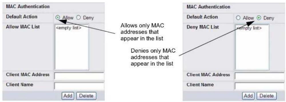
To add a wireless client to the MAC Authentication list, enter the MAC address of the client in the MAC Address field and click Add. You must click Submit to apply the changes.
- Click Clear to reset the page to the default values.
- Click Refresh to update the screen with the most current information.
- The Next button appears on this page when it is opened through the Administration > Basic Setup page. Click Next to navigate to the Wireless Default Radio Configuration page.
The following table describes the MAC Authentication fields in more detail.
Table 10: MAC Authentication
| Field Description | |
| Default Action The default action is the action that is taken for unknown MAC addresses of wireless clients that attempt to associate with an access point.Allow—Only the clients you explicitly add to this list are allowed access to APs that use MAC Authentication.Deny—Only the clients you explicitly add to this list are denied access to APs that use MAC Authentication. | |
| Allow MAC List This list shows the MAC address of the wireless clients that have already been added to the list of wireless clients to allow or deny access to the APs. | |
| Client MAC Address Enter the MAC address of the wireless client to allow or deny access to all APs that use this profile. |
Table 10: MAC Authentication
| Field Description | |
| Client Name Enter the name of the wireless client to allow or deny access to allAPs that use this profile. This is a user-friendly name of up to 32 printable ASCII characters assigned to a client entry in the local Client MAC Authentication list. This is a configurable parameter and persists over switch reboots. The client name cannot be assigned to a client entry on a RADIUS server.The client name is assigned at the time of creating a client entry in the local MAC Authentication list. To modify the name of an existing client entry, the entry needs to be deleted and then re-added with the changed name. |
Configuring Wireless Radio Settings
The DWL-3500AP supports one radio that operates in IEEE 802.11g mode. The DWL-8500AP supports two radios: Radio 1 operates in IEEE 802.11a mode, and Radio 2 operates in IEEE 802.11g mode. The DWL-8600AP supports two radios operating in IEEE 802.11n mode.
The DWL-8600AP with Broadcom 802.11n radios works in a Managed mode if a managing DWS-3000 or DWS-4000 switch is found. Otherwise it works as a Standalone AP. The DWL-8600AP supports all the non-Atheros wireless and wired features that DWL-8500AP and DWL-3500AP support, except that both radios of the DWL-8600AP support 802.11a/b/g/n and the Ethernet interface supports speeds up to 1 Gbps.
The difference between the IEEE 802.11 modes is the frequency in which they operate. IEEE 802.11g operates in the 2.4 GHz frequency, and IEEE 802.11a operates in the 5 GHz frequency of the radio spectrum.
You configure the default radio settings from the Administration > Basic Setup > Radio tab, which Figure 38 shows.

Note: The radio settings for the IEEE 802.11g radio are directly below the settings for the IEEE 802.11a radio. When the profile is applied to the DWL-3500AP, only the settings for the IEEE 802.11g radio are applied.
Figure 38: Radio Settings
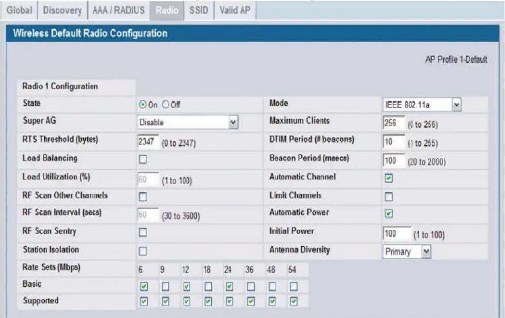
The following table describes the fields you can configure from the Radio tab on the Basic Setup page. After you change the settings, click Submit to apply the settings.
Table 11: Radio Settings
| Field Description | |
| State | Specify whether you want the radio on or off by clicking On or Off.If you turn off a radio, the AP sends disassociation frames to all the wireless clients it is currently supporting so that the radio can be gracefully shutdown and the clients can start the association process with other available APs. |
| Super ASuper G | Super A and Super G attempt to increases performance through bursting and frame compression. Performance increases when the AP communicates with Super A and Super G-enabled clients. However, with Super A and Super G enabled, the access point transmissions consume more bandwidth.To enable Super A or Super G, select Enabled.To disable Super A or Super G, select Disabled.To enable Super A or Super G with Dynamic Turbo, select Enable with Dynamic Turbo. |
| RTS Threshold | The RTS threshold indicates the size of the data packet above which an RTS packet should be sent. This helps control traffic flow through the access point, especially one with a lot of clients.If you specify a low threshold value, RTS packets will be sent more frequently. This will consume more bandwidth and reduce the throughput of the packet.On the other hand, sending more RTS packets can help the network recover from interference or collisions which might occur on a busy network, or on a network experiencing electromagnetic interference.The RTS Threshold value can be between 0 and 2347. |
Table 11: Radio Settings
| Field | Description |
| Load Balancing | If you enable load balancing, you can control the amount of traffic that is allowed on the AP. |
| Load Utilization | This field allows you to set a threshold for the percentage of network bandwidth utilization allowed on the radio. Once the level you specify is reached, the AP stops accepting new client associations.If you specify 0 in this field, all new associations will be allowed regardless of the utilization rate. |
| RF Scan Other Channels | The access point can perform RF scans to collect information about other wireless devices within range and then report this information to the Unified Switch.If you select the Scan Other Channels check box, the radio periodically moves away from the operational channel to scan other channels.Enabling this mode causes the radio to interrupt user traffic, which may be noticeable with voice connections. Changing the channels also causes the radio to lose auto-calibration settings which may degrade the signal quality.When the Scan Other Channels check box is not enabled the AP scans only the operating channel. |
| RF Scan Interval | This field controls the length of time between channel changes during the RF Scan. |
| RF Scan Sentry | If you select the RF Scan Sentry check box, the radio primarily performs dedicated RF scanning. The radio passively listens for beacons and traffic exchange between clients and other access points but does not accept connections from wireless clients. In sentry mode, all VAPs are disabled.In this mode, the radio switches from one channel to the next. The length of time spent on each channel is controlled by the scan duration. The default scan duration is 10 milliseconds. |
| RF Scan Sentry Channels | The radio can scan channels in the radio frequency used by the 802.11b/g band, the 802.11a band, or both bands. Select the channel band for the radio to scan.Note: The band selection applies only to radios in sentry mode. |
| Station Isolation | Select the check box to enable Station Isolation, or clear it to disable station isolation.Enabled: Access point blocks communication between wireless clients. The access point still allows data traffic between its wireless clients and wired devices on the network, but not among wireless clients.Disabled: Wireless clients can communicate with one another normally by sending traffic through the access point.Note: Station Isolation is operational only for clients that transmit non-tunneled traffic. When client traffic is tunneled, Station Isolation is not in effect for those clients even if it is enabled.Note: Station Isolation is configured independently for each radio. You cannot configure Station Isolation on a per-SSID or per-AP basis. |
| Rate Sets | Check the transmission rate sets you want the access point to support and the basic rate sets you want the access point to advertise.Rates are expressed in megabits per second. |
| Basic | These numbers indicate rates that the access point will advertise to the network for the purposes of setting up communication with other APs and client stations on the network. It is generally more efficient to have an AP broadcast a subset of its supported rate sets. |
| Supported | These numbers indicate rates that the access point supports. You can check multiple rates (click a check box to select or de-select a rate). The AP automatically chooses the most efficient rate based on factors like error rates and distance of client stations from the AP. |
Table 11: Radio Settings
| Field Description | |
| Mode The Mode defines the Physical Layer (PHY) standard the radio uses.The DWL-3500AP and Radio 1 on the DWL-8500AP use the IEEE 802.11g mode PHY standard. This mode is a higher speed extension (up to 54 Mbps) to the 802.11b PHY, while operating in the 2.4 GHz band. It uses orthogonal frequency division multiplexing (OFDM). It supports data rates ranging from 1 to 54 Mbps. IEEE 802.11b clients can use the 802.11g mode.Radio 2 on the DWL-8500AP use the IEEE 802.11a mode, which is a PHY standard that specifies operating in the 5 GHz U-NII band using orthogonal frequency division multiplexing (OFDM). It supports data rates ranging from 6 to 54 Mbps.The DWL-8600AP supports:Radio 1: IEEE 802.11b/g, IEEE 802.11b/g/n, 2.4 GHz IEEE 802.11nRadio 2: IEEE 802.11a, IEEE 802.11a/n, and 5 GHz IEEE 802.11nIf the radio state is disabled, the mode displays as Off. | |
| Maximum Clients | Specify the maximum number of stations allowed to access this access point at any one time.You can enter a value between 0 and 256. |
| DTIM Period | The Delivery Traffic Information Map (DTIM) message is an element included in some beacon frames. It indicates which client stations, currently sleeping in low-power mode, have data buffered on the access point awaiting pick-up.The DTIM period you specify indicates how often the clients served by this access point should check for buffered data still on the AP awaiting pickup.Specify a DTIM period within the given range (1 - 255).The measurement is in beacons. For example, if you set this field to “1” clients will check for buffered data on the AP at every beacon. If you set this field to 10, clients will check on every 10th beacon. |
| Beacon Period | Beacon frames are transmitted by an access point at regular intervals to announce the existence of the wireless network. The default behavior is to send a beacon frame once every 100 milliseconds (or 10 per second).The Beacon Interval value is set in milliseconds. Enter a value from 20 to 2000. |
| Automatic Channel | The channel defines the portion of the radio spectrum that the radio uses for transmitting and receiving. The range of channels and the default channel are determined by the Mode of the radio interface.When the AP boots, the AP scans the RF area for occupied channels and selects a channel from the available non-interfering, or clear channels. However, channel conditions can change during operation.Enabling the Automatic Channel makes APs assigned to this profile eligible for auto-channel selection. You can automatically or manually run the auto-channel selection algorithm to allow the Unified Switch to adjust the channel on APs as WLAN conditions change.By default, the global auto-channel mode is set to manual. To enable the automatic channel selection mode, go to the AP Management > RF Management page and select Fixed or Interval for the Channel Plan mode. You can also run the automatic channel selection algorithm manually from the Manual Channel Plan page.Note:If you assign a static channel to an AP in the Valid AP database or on the Advanced AP Management page, the AP will not participate in the auto-channel selection. |
| Limit Channels | If the radio is operating in 802.11a mode, you can select the Limit Channels check box to allow the AP to select from the available channels.Note:The available channels depend on the country in which the APs operate.If the Limit Channels option is not selected, the AP can also broadcast on channels 149, 153, 157, 161, and 165. Some legacy 802.11a adapters might not support these higher channel numbers. |
Table 11: Radio Settings
| Field Description | |
| Automatic Power | The power level affects how far an AP broadcasts its RF signal. If the power level is too low, wireless clients will not detect the signal or experience poor WLAN performance. If the power level is too high, the RF signal might interfere with other APs within range.Automatic power uses a proprietary algorithm to automatically adjust the RF signal to broadcast far enough to reach wireless clients, but not so far that it interferes with RF signals broadcast by other APs. The power level algorithm increases or decreases the power level in 10% increments based on presence or absence of packet retransmission errors. |
| Initial Power | The automatic power algorithm will not reduce the power below the number you set in the initial power field. By default, the power level is 100%. Therefore, even if you enable the automatic power, the power of the RF signal will not decrease.The power level is a percentage of the maximum transmission power for the RF signal. |
| Antenna Diversity Select the antenna use to receive and transmit wireless traffic:• Auto : Automatically select the best antenna to send and receive traffic.• Primary: Use the primary antenna to send and receive traffic.• Secondary: Use the secondary antenna to send and receive traffic. | |
Use the buttons at the bottom of the page to perform the following tasks:
- Click Clear to reset the page to the default values.
- Click Refresh to update the screen with the most current information.
- Click Submit to update the switch with the values on the screen. If you want the switch to retain the new values across a power cycle you must perform a save.
- The Next button appears on this page when it is opened through the Administration > Basic Setup page. Click Next to navigate to the SSID > Wireless Default VAP Configuration page.
If you access the Access Point Profile Radio Configuration through the Advanced Configuration > AP Profiles > Radio tab, some additional fields are available for configuration.
The following table describes the fields for the AP radio that are only available from the Advanced Configuration menu.
Table 12: Advanced Radio Configuration
| Field Description | |
| RF Scan Duration | This field controls the amount of time the radio spends scanning the other channel (in milliseconds) during an RF scan. |
| Transmit Lifetime | Shows the number of milliseconds to wait before terminating attempts to transmit the MSDU after the initial transmission. |
| Receive Lifetime | Shows the number of milliseconds to wait before terminating attempts to reassemble the MMPDU or MSDU after the initial reception of a fragmented MMPDU or MSDU. |
| Frag Threshold | The fragmentation threshold limits the size of packets transmitted over the network.Acceptable values are even numbers from 256-2345. Packets that are under the configured size are not fragmented. A value of 2346 means that packets are not fragmented. |
| Short Retries | The value in this field indicates the maximum number of transmission attempts on frame sizes less than or equal to the RTS Threshold. The range is 1-255. |
| Long Retries | The value in this field indicates the maximum number of transmission attempts on frame sizes greater than the RTS Threshold. The range is 1-255. |
Table 12: Advanced Radio Configuration
| Field Description | |
| 802.11n Protection | When an IEEE 802.11n mode is selected, configure either Auto or Off for 802.11n protection. Not all countries that allow 802.11b/g/a also allow 802.11n. If the administrator selects a mode other than 802.11n, then the 802.11n Protection field is disabled. |
| Channel Bandwidth | When an IEEE 802.11n mode is selected, select either 20 MHz or 40MHz. If the administrator selects a mode other than 802.11n, then the Channel Bandwidth field is disabled. |
| Primary Channel | When an IEEE 802.11n mode is selected, select either Lower or Upper as the primary channel. If the administrator selects a mode other than 802.11n, then the Primary Channel field is disabled. |
Configuring SSID Settings
The SSID tab displays the virtual access point (VAP) settings associated with the default AP profile. Each VAP has an associated network, which is identified by its network number and Service Set Identifier (SSID). Each radio in the configuration profile has 16 VAPs/SSID to configure but, when the profile is applied to a DWL-x500AP, only the first 8 VAPs are applied and the rest 8 VAPs are ignored. This is because the DWL-x500AP supports 8 VAPs. All 16 VAPs are applied to a DWL-8600AP.
Figure 39: VAP Settings
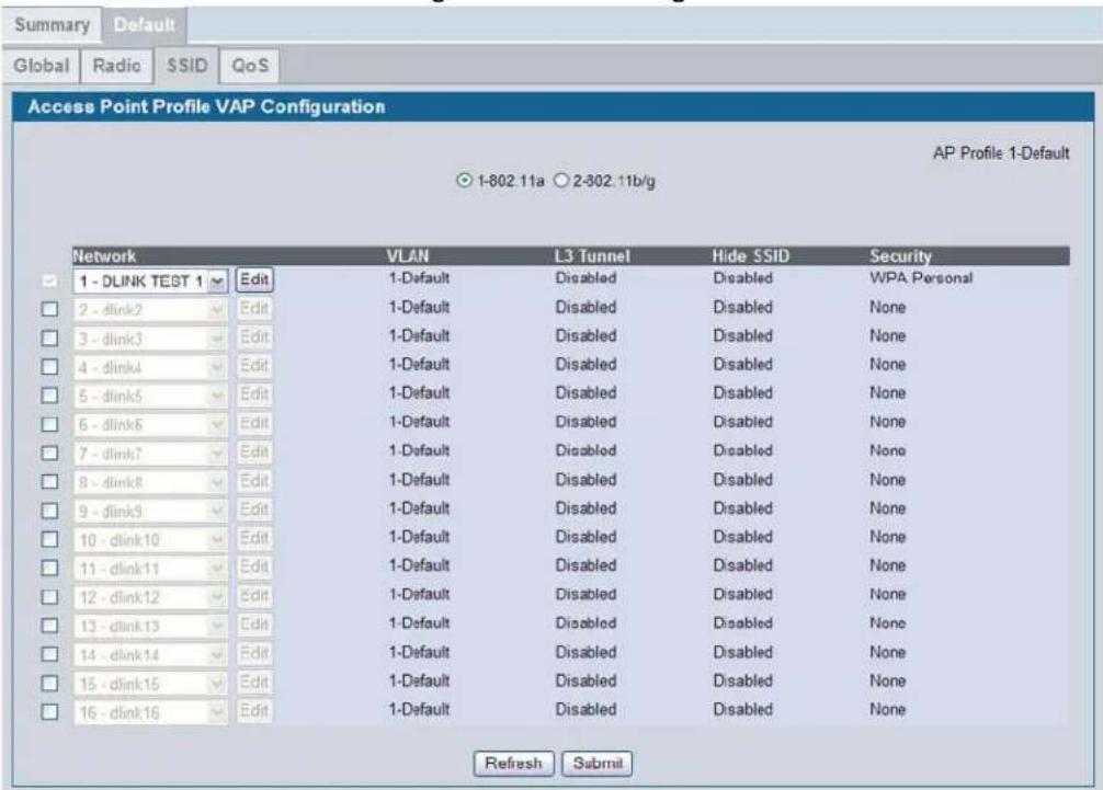
VAPs segment the wireless LAN into multiple broadcast domains that are the wireless equivalent of Ethernet VLANs. To a wireless client, each VAP appears to be a single physical access point. However, since the VAPs use the same channel, there is no risk of RF interference among the networks that are on a single AP.
VAPs can help you maintain better control over broadcast and multicast traffic, which affects network performance. You can also configure different security mechanisms for each VAP.
A VAP is a "physical" entity. Each VAP maps directly to a MAC address. A network is a logical entity that you apply to a VAP. Networks are identified by a network number and an associated SSID. The SSID does not need to be unique for each network. You can create and modify a network in one place and apply the network to one or more VAP as needed. This allows you to mix networks within different profiles without having to reconfigure everything. When you edit a network configuration that is applied to more than one VAP, you edit it for every VAP that uses the network.
Managing Virtual Access Point Configuration
The Default AP profile has one VAP enabled by default. The default VAP uses the dlink1 SSID, and there is no security to prevent wireless clients from associating with the VAP. To enable additional VAPs, select the check box next to the VAP. Once you enable a VAP, you can select the network (SSID) to use from the menu. To change Network settings, click Edit to navigate to the "Wireless Network Configuration" on page 88.
The following table describes the fields on the SSID page.
Table 13: Default VAP Configuration
| Field Description | |
| Radio 1Radio 2 | You configure the VAPs for Radio 1 and Radio 2 separately. Select the radio to configure the settings for before you enable the VAP. |
| Check Box | This check box enables or disables the corresponding VAP on the radio. When checked, the VAP is enabled. The SSID field on the page is also enabled to allow network selection for the VAP.Note: You cannot disable the default VAP, VAP0. |
| Network | The menu lists the available networks that you can assign to the VAP. You can configure up to 64 separate networks on the switch and apply them across multiple radio and VAP interfaces. By default, eight networks are pre-configured and applied in order to the VAPs on each radio.To configure additional networks, click Advanced Configuration > Networks. |
| Edit | Click Edit to modify settings for the corresponding network.When you click edit, the Wireless Network Configuration page appears. |
| VLAN | Shows the VLAN ID of the VAP. To change this setting, click Edit. |
| L3 Tunnel | Shows whether L3 Tunneling is enabled on the VAP. To change this setting, click Edit.Note: When L3 tunneling is enabled the VLAN ID is not used. In fact, the switch puts the management VLAN ID, if any, on the tunneled packets. |
| Hide SSID | Shows whether the VAP broadcasts the SSID. If enabled, the SSID for this network is not included in AP beacons. To change this setting, click Edit. |
| Security | Shows the current security settings for the VAP. To change this setting, click Edit. |
Use the buttons at the bottom of the page to perform the following tasks:
- Click Refresh to update the screen with the most current information.
- Click Submit to update the switch with the values on the screen. If you want the switch to retain the new values across a power cycle you must perform a save.
- The Next button appears on this page when it is opened through the Administration > Basic Setup page. Click Next to navigate to the “Configuring Valid Access Point Settings” on page 101.
Each network is identified by its Service Set Identifier (SSID), which is an alphanumeric key that identifies a wireless local area network. You can configure up to 64 different networks on the D-Link Unified Switch. Each network can have a unique SSID, or you can configure multiple networks with the same SSID.
When you click Edit on the VAP page, the Wireless Network Configuration page appears, as Figure 40 shows.
Figure 40: Configuring Network Settings
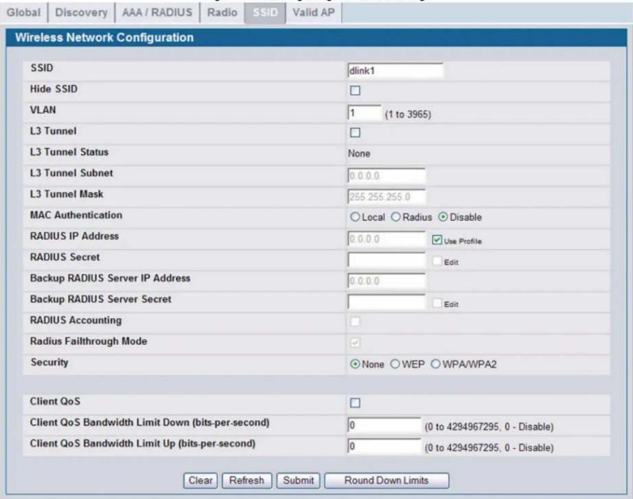
Table 14 describes the fields on the Wireless Network Configuration page.
Table 14: Wireless Network Configuration
| Field Description | |
| SSID | Wireless clients identify a wireless network by the SSID, which is an alphanumeric key that uniquely identifies a wireless local area network. The SSID can be up to thirty-two characters in length, and there are no restrictions on the characters that may be used in an SSID. |
| Hide SSID | You can hide the SSID broadcast to discourage stations from automatically discovering your access point. When the broadcast SSID of the AP is hidden, the network name is not displayed in the list of available networks on a client station. Instead, the client must have the exact network name configured in the supplicant before it is able to connect.Disabling the broadcast SSID is sufficient to prevent clients from accidentally connecting to your network, but it will not prevent even the simplest of attempts by a hacker to connect, or monitor unencrypted traffic.This offers a very minimal level of protection on an otherwise exposed network (such as a guest network) where the priority is making it easy for clients to get a connection and where no sensitive information is available. |
| VLAN | A virtual LAN (VLAN) is a software-based, logical grouping of devices on a network that allow them to act as if they are connected to a single physical network, even though they may not be. The nodes in a VLAN share resources and bandwidth, and are isolated on that network.The D-Link Unified Access System supports the configuration of a wireless VLAN. You can configure each VAP to be on a unique VLAN or on the same VLAN as other VAPs.When a wireless client connects to the AP by using this network (SSID), the AP tags the client's traffic with the VLAN ID you configure in this field. By default, all networks use VLAN 1, which is also untagged by default.Note: The VLAN ID you configure in this field can be overwritten by the VLAN ID configured for the AP in the RADIUS server. In other words, if your network uses a RADIUS server to assign wireless clients to VLANs, the wireless client uses the VLAN ID from the RADIUS server and ignores the VLAN ID configured on the VAP. |
| L3 Tunnel | The L3 Tunnel feature allows mobile stations to maintain their IP connections while roaming from one access point to another access point even when these access points are attached to different IP subnets.Note: When L3 tunneling is enabled the VLAN ID is not used. In fact, the switch puts the management VLAN ID, if any, on the tunneled packets.Note: If the wireless network topology changes (for example, a DWS-3000 switch reboots) while the L3 tunneling feature is in use, you should perform an ARP refresh on wired clients to speed up the process of re-establishing connectivity to the tunneled network.Before you enable this feature, make sure your network meets the design requirements described in “Network Planning to Support Layer 3 Roaming” on page 37.For more information about the L3 Roaming network, see “Configuring a VAP for L3 Tunnels” on page 95. |
| L3 Tunnel Status | This field shows the status of L3 Tunneling. In order for tunnel to be completely configured, routing must be enabled and the switch must have a routing interface IP address that is in the tunnel subnet. The status can be one of the following:None (L3 Tunnel is disabled or the network is not associated with any AP profiles)ConfiguredNot Configured - Routing DisabledNot Configured - No Routing Interface |
| L3 Tunnel Subnet | The network IP address you enter in this field must be in the same subnet as a routing interface for the WLAN that you define on the switch. |
| L3 Tunnel Mask | Enter the subnet mask for the network IP address on the L3 Tunnel subnet. |
Table 14: Wireless Network Configuration
| Field Description | |
| MAC Authentication | If you enable MAC authentication, wireless clients must be authenticated by the AP in order to connect to the network. You must configure the MAC addresses of the clients to accept or deny (based on the default action you set in the AP profile) in one of the following databases:LocalRADIUS |
| RADIUS IP Address | If you use a RADIUS server to authenticate wireless clients, you can use the same RADIUS server that you configure on the AAA/RADIUS tab for the profile, or you can specify a different RADIUS server.To specify a RADIUS server for this VAP, clear the Use Profile check box and enter the IP address of the RADIUS server in the field. |
| RADIUS Secret | To enter a RADIUS secret, select the Edit check box and type the secret in the field. |
| Backup RADIUS Server IP Address | The IP address of the backup radius server. |
| Backup RADIUS Server Secret | The RADIUS secret of the backup radius server. |
| RADIUS Accounting | Select the RADIUS Accounting check box to enable accounting for wireless clients on the specified RADIUS server. |
| RADIUS Failthrough Mode | Select the RADIUS Failthrough Mode option to enable the radius fail-through feature. Clear the option to disable the feature. |
| Security | The default AP profile does not use any security mechanism by default. In order to protect your network, we strongly recommend that you select a security mechanism so that unauthorized wireless clients cannot gain access to your network.The following WLAN network security options are available:NoneWEPWPA/WPA2If you select WEP or WPA/WPA2 as your security mechanism, a dialogue box asks if you want to change network security. After you click OK, additional fields appear, and any network settings that you modified are applied to the switch."Configuring AP Security" on page 97 describes the security mechanisms and the additional fields you can configure if you select WEP or WPA/WPA2. |
Table 14: Wireless Network Configuration
| Field Description | |
| Client QoS | The Client QoS parameters allow the switch to apply access control lists (ACLs) and differentiated service (DiffServ) policies to wireless clients associated to the AP and extend the switch QoS features into the wireless domain.Select this option to enable Client QoS operation for wireless clients that associate with the AP using the SSID in the previous field.Client QoS provides control over certain QoS aspects of wireless clients that connect to the network, such as the amount of bandwidth and type of traffic an individual client is allowed to send and receive. To control general categories of traffic, such as HTTP traffic or traffic from a specific subnet, you can configure ACLs and assign them to one or more VAPs. Client QoS also allows you to configure per-client conditioning of various micro-flows through DiffServ.ACLs are a collection of permit and deny conditions, called rules, that provide security by blocking unauthorized users and allowing authorized users to access specific resources.ACLs can block any unwarranted attempts to reach network resources.Each ACL is a set of up to ten rules applied to traffic sent from a wireless client or to be received by a wireless client. Each rule specifies whether the contents of a given field should be used to permit or deny the packet from being transmitted. Rules can be based on various criteria and may apply to one ore more fields within a packet, such as the source or destination IP address, the source or destination L4 port, or the protocol carried in the packet.DiffServ policies are a useful tool for establishing general micro-flow definition and treatment characteristics that can be applied to each wireless client, both inbound and outbound, when it is authenticated on the network. Packets are classified and processed based on defined criteria. The classification criteria is defined by a class. The processing is defined by a policy's attributes. |
| Client QoS Bandwidth Limit Down (bits-per-second) | Enter the maximum allowed transmission rate from the AP to the wireless client in bits per second. The valid range is 0-4294967295 bps. A value of 0 means that the bandwidth maximum limit is not enforced in this direction.Note:Client QoS is only supported when DWL-8600AP is managed by a DWS-3000 switch. |
| Client QoS Bandwidth Limit Up (bits-per-second) | Enter the maximum allowed client transmission rate to the AP in bits per second. The valid range is 0-4294967295 bps. A value of 0 means that the bandwidth maximum limit is not enforced in this direction. |
Use the buttons at the bottom of the page to perform the following tasks:
- Click Clear to reset the page to the default values.
- Click Refresh to update the screen with the most current information.
• After you change the wireless network settings, click Submit to save the changes. - Because Client QoS Bandwidth Limit Down and the Client QoS Bandwidth Limit Up have to be set to n*64000 bits/sec (n = 0, 1, 2, ...), click the Round Down Rates button to:
- Round down the values to the nearest multiple of 64000 bits/sec if the value entered is greater than 64000 bits/sec.
- Round up to 64000 bits/sec if the value entered is less than 64000 bits/sec.
Another way to navigate to the Wireless Network Configuration page:
1 Click WLAN > Administration > Advanced Configuration > Networks to display the Wireless Network Summary page
2 Click any network SSID to navigate to the Wireless Network Configuration page.
WIRELESS NETWORK SUMMARY
To navigate to the Wireless Network Summary page, click WLAN > Administration > Advanced Configuration > Networks.
Table 15: Wireless Network Summary
| Field Description | |
| SSID Wireless clients identify a wireless network by the SSID, which is an alphanumeric key that uniquely identifies a wireless local area network. The SSID can be up to thirty-two characters in length, and there are no restrictions on the characters that may be used in an SSID. | |
| VLAN A virtual LAN (VLAN) is a software-based, logical grouping of devices on a network that allow them to act as if they are connected to a single physical network, even though they may not be. The nodes in a VLAN share resources and bandwidth, and are isolated on that network.The D-Link Unified Access System supports the configuration of a wireless VLAN. You can configure each VAP to be on a unique VLAN or on the same VLAN as other VAPs.When a wireless client connects to the AP by using this network (SSID), the AP tags the client's traffic with the VLAN ID you configure in this field. By default, all networks use VLAN 1, which is also untagged by default.Note:The VLAN ID you configure in this field can be overwritten by the VLAN ID configured for the AP in the RADIUS server. In other words, if your network uses a RADIUS server to assign wireless clients to VLANs, the wireless client uses the VLAN ID from the RADIUS server and ignores the VLAN ID configured on the VAP. | |
| Hide SSID You can hide the SSID broadcast to discourage stations from automatically discovering your access point. When the broadcast SSID of the AP is hidden, the network name is not displayed in the list of available networks on a client station. Instead, the client must have the exact network name configured in the supplicant before it is able to connect.Disabling the broadcast SSID is sufficient to prevent clients from accidentally connecting to your network, but it will not prevent even the simplest of attempts by a hacker to connect, or monitor unencrypted traffic.This offers a very minimal level of protection on an otherwise exposed network (such as a guest network) where the priority is making it easy for clients to get a connection and where no sensitive information is available. | |
| L3 Tunnel The L3 Tunnel feature allows mobile stations to maintain their IP connections while roaming from one access point to another access point even when these access points are attached to different IP subnets.Note:When L3 tunneling is enabled the VLAN ID is not used. In fact, the switch puts the management VLAN ID, if any, on the tunneled packets.Note:If the wireless network topology changes (for example, a DWS-3000 switch reboots) while the L3 tunneling feature is in use, you should perform an ARP refresh on wired clients to speed up the process of re-establishing connectivity to the tunneled network.Before you enable this feature, make sure your network meets the design requirements described in “Network Planning to Support Layer 3 Roaming” on page 37.For more information about the L3 Roaming network, see “Configuring a VAP for L3 Tunnels” on page 95. | |
| Security The default AP profile does not use any security mechanism by default. In order to protect your network, we strongly recommend that you select a security mechanism so that unauthorized wireless clients cannot gain access to your network.The following WLAN network security options are available:NoneWEPWPA/WPA2If you select WEP or WPA/WPA2 as your security mechanism, a dialogue box asks if you want to change network security. After you click OK, additional fields appear, and any network settings that you modified are applied to the switch.Configuring AP Security” on page 97 describes the security mechanisms and the additional fields you can configure if you select WEP or WPA/WPA2. |
Click Refresh to update the Wireless Network Summary page with the most current information.
D-Link's Adaptable Wireless technology provides you with the choice to associate a wireless network (SSID) with a VLAN or a tunneled subnet. To associate an SSID with a VLAN, enter a VLAN ID in the VLAN field. To associate an SSID with a tunneled subnet, enable L3 Tunnel and complete the L3 Tunnel Subnet and L3 Tunnel Mask fields.
The Adaptable Wireless technology offers maximized flexibility. The wireless application can determine how traffic is handled. For example, guest traffic can be tunneled to the switch for centralized security control, and VoIP traffic can be tagged with a VLAN ID and forwarded directly from the access point for optimal performance.
Enabling and Configuring Additional VAPs
When a wireless client searches for available wireless networks, each VAP you enable on the VAP tab appears as a separate network to the wireless client. Figure 41 shows an example of an AP Profile with a VAP enabled. Each VAP uses a different network.
Figure 41: AP Profile With VAP Enabled
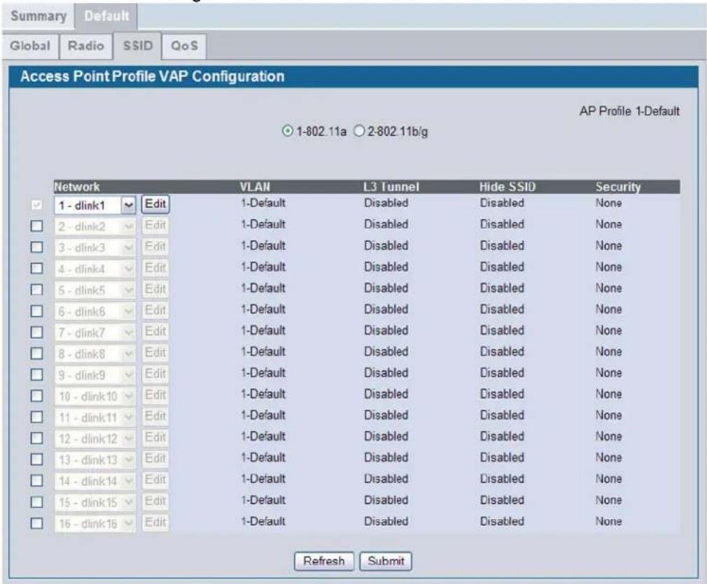
Figure 42 shows what a user on a Microsoft Windows XP client sees when the user searches for wireless networks within range.
Figure 42: Networks Available to the Wireless Client
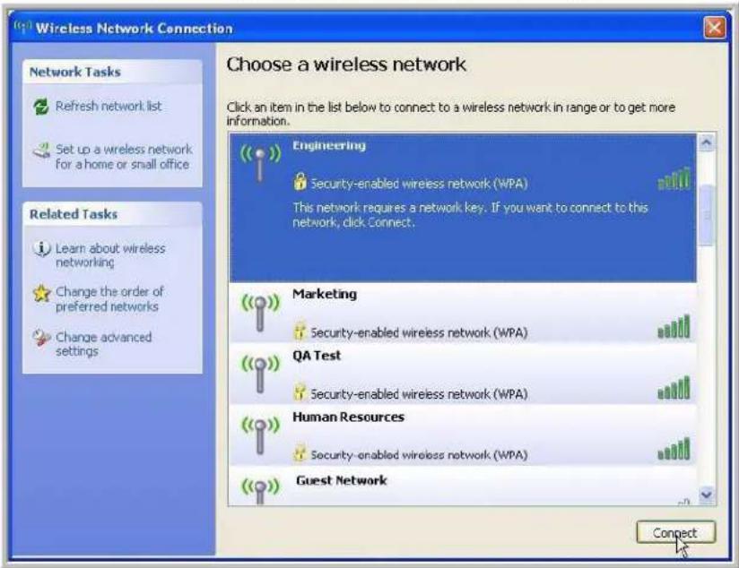
Although the wireless client finds five different wireless networks, these networks are all on the same access point. The D-Link Access Point looks like five separate access points to the wireless client.
In this example, the administrator configured multiple VAPs based on different functional groups within the company. Each VAP has a different SSID, security settings, and VLAN ID to separate traffic.
You can associate the same network (SSID) with multiple VAPs. When you do this, the VAPs look like the same network to wireless clients. Some administrators configure VAPs with identical settings on each radio so that wireless clients can connect to the same network whether their wireless adapters are 802.11a or 802.11b/g compatible.
By default, both radios have the same networks assigned to the VAPs, and only VAP0 is enabled. You must configure each radio independently. In other words, if you enable additional VAPs on one radio, it does not affect the VAPs on the second radio.
Configuring a VAP for L3 Tunnels
This section provides an overview of the L3 Tunneling feature. For a detailed configuration example of a network that uses L3 roaming, see Appendix Appendix C:, "L3 Roaming Example" on page 213.
The L3 Tunnel feature allows mobile stations to maintain their IP connections while roaming from one access point to another access point even when these access points are attached to different IP subnets. This feature is especially useful for environments that use wireless Voice over IP (VoIP) on the 802.11 networks with multiple subnets. See "Configuring QoS" on page 160.
If you enable L3 tunnels, we recommend that you enable and configure a separate VAP for clients that need to use this feature. Configure clients that need L3 Tunneling to connect to the SSID with L3 tunnels enabled, but configure all other wireless clients to use the VAP with L3 tunnels disabled.
In general, only clients that transmit and receive time-sensitive data while roaming need to take advantage of this feature. Figure 43 shows a network with two APs that are controlled by a D-Link Unified Switch. The APs and switch are all on different subnets.
Figure 43: L3 Roaming Example
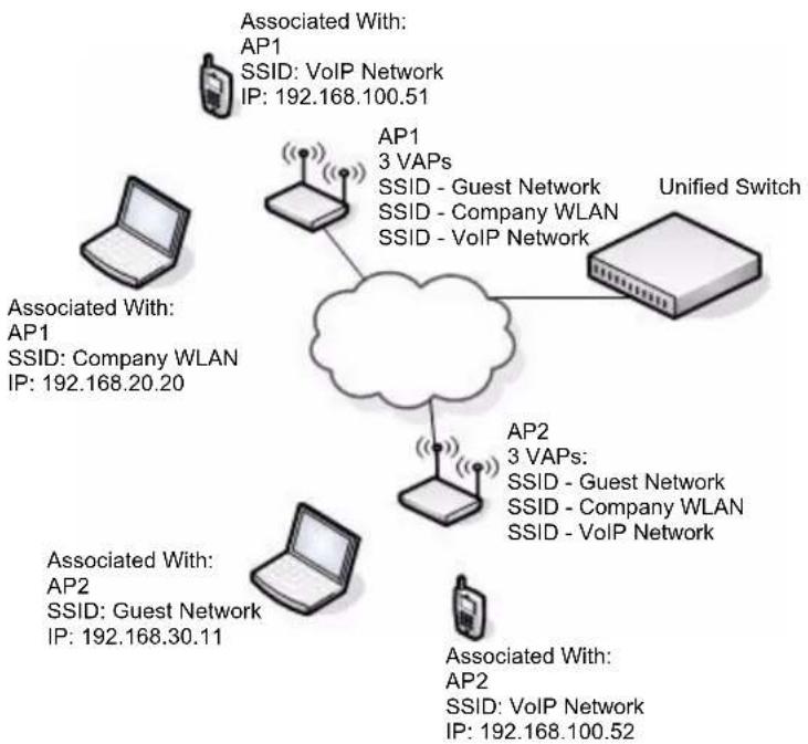
flowchart
graph TD
    A["AP1"] --> B["Unified Switch"]
    C["AP1: 3 VAPs\nSSID - Guest Network\nSSID - Company WLAN\nSSID - VoIP Network"] --> B
    D["AP2"] --> E["Unified Switch"]
    F["AP2: 3 VAPs:\nSSID - Guest Network\nSSID - Company WLAN\nSSID - VoIP Network"] --> E
    G["AP2: 3 VAPs:\nSSID - Guest Network\nSSID - Company WLAN\nSSID - VoIP Network"] --> E
    H["AP2: 3 VAPs:\nSSID - Guest Network\nSSID - Company WLAN\nSSID - VoIP Network"] --> E
    I["AP2: 3 VAPs:\nSSID - Guest Network\nSSID - Company WLAN\nSSID - VoIP Network"] --> E
    J["AP2: 3 VAPs:\nSSID - Guest Network\nSSID - Company WLAN\nSSID - VoIP Network"] --> E
    K["AP2: 3 VAPs:\nSSID - Guest Network\nSSID - Company WLAN\nSSID - VoIP Network"] --> E
    L["AP2: 3 VAPs:\nSSID - Guest Network\nSSID - Company WLAN\nSSID - VoIP Network"] --> E
    M["AP2: 3 VAPs:\nSSID - Guest Network\nSSID - Company WLAN\nSSID - VoIP Network"] --> E
    N["AP2: 3 VAPs:\nSSID - Guest Network\nSSID - Company WLAN\nSSID - VoIP Network"] --> E
    O["AP2: 3 VAPs:\nSSID - Guest Network\nSSID - Company WLAN\nSSID - VoIP Network"] --> E
    P["AP2: 3 VAPs:\nSSID - Guest Network\nSSID - Company WLAN\nSSID - VoIP Network"] --> E
    Q["AP2: 3 VAPs:\nSSID - Guest Network\nSSID - Company WLAN\nSSID - VoIP Network"] --> E
    R["AP2: 3 VAPs:\nSSID - Guest Network\nSSID - Company WLAN\nSSID - VoIP Network"] --> E
    S["AP2: 3 VAPs:\nSSID - Guest Network\nSSID - Company WLAN\nSSID - VoIP Network"] --> E
    T["AP2: 3 VAPs:\nSSID - Guest Network\nSSID - Company WLAN\nSSID - VoIP Network"] --> E
    U["AP2: 3 VAPs:\nSSID - Guest Network\nSSID - Company WLAN\nSSID - VoIP Network"] --> E
    V["AP2: 3 VAPs:\nSSID - Guest Network\nSSID - Company WLAN\nSSID - VoIP Network"] --> E
    W["AP2: 3 VAPs:\nSSID - Guest Network\nSSID - Company WLAN\nSSID - VoIP Network"] --> E
    X["AP2: 3 VAPs:\nSSID - Guest Network\nSSID - Company WLAN\nSSID - VoIP Network"] --> E
    Y["AP2: 3 VAPs:\nSSID - Guest Network\nSSID - Company WLAN\nSSID - VoIP Network"] --> E
    Z["AP2: 3 VAPs:\nSSID - Guest Network\nSSID - Company WLAN\nSSID - VoIP Network"] --> E
    AA["AP2: 3 VAPs:\nSSID - Guest Network\nSSID - Company WLAN\nSSID - VoIP Network"] --> E
    AB["AP2: 3 VAPs:\nSSID - Guest Network\nSSID - Company WLAN\nSSID - VoIP Network"] --> E
    AC["AP2: 3 VAPs:\nSSID - Guest Network\nSSID - Company WLAN\nSSID - VoIP Network"] --> E
    AD["AP2: 3 VAPs:\nSSID - Guest Network\nSSID - Company WLAN\nSSID - VoIP Network"] --> E
    AE["AP2: 3 VAPs:\nSSID - Guest Network\nSSID - Company WLAN\nSSID - VoIP Network"] --> E
    AF["AP2: 3 VAPs:\nSSID - Guest Network\nSSID - Company WLAN\nSSID - VoIP Network"] --> E
    AG["AP2: 3 VAPs:\nSSID - Guest Network\nSSID - Company WLAN\nSSID - VoIP Network"] --> E
    AH["AP2: 3 VAPs:\nSSID - Guest Network\nSSID - Company WLAN\nSSID - VoIP Network"] --> E
    AI["AP2: 3 VAPs:\nSSID - Guest Network\nSSID - Company WLAN\nSSID - VoIP Network"] --> E
    AJ["AP2: 3 VAPs:\nSSID - Guest Network\nSSID - Company WLAN\nSSID - VoIP Network"] --> E
    AK["AP2: 3 VAPs:\nSSID - Guest Network\nSSID - Company WLAN\nSSID - VoIP Network"] --> E
    AL["AP2: 3 VAPs:\nSSID - Guest Network\nSSID - Company WLAN\nSSID - VoIP Network"] --> E
    AM["AP2: 3 VAPs:\nSSID - Guest Network\nSSID - Company WLAN\nSSID - VoIP Network"] --> E
    AN["AP2: 3 VAPs:\nSSID - Guest Network\nSSID - Company WLAN\nSSID - VoIP Network"] --> E
    AO["AP2: 3 VAPs:\nSSID - Guest Network\nSSID - Company WLAN\nSSID - VoIP Network"] --> E
    AP["AP1"] --> AP1
    AP1 --> AP1
    AP1 --> AP1
    AP1 --> AP1
    AP1 --> AP1
    AP1 --> AP1
Both of the APs in Figure 43 use the same default profile. The default profile has three virtual access points (VAPs) enabled, and each VAP uses a different network (SSID). When users search for available wireless networks, all three SSIDs appear in the list of networks. The laptop clients connect to the Company WLAN or Guest Network, and the VoIP phones connect to the VoIP Network.
The L3 Tunnel feature is enabled on the VoIP network, but it is disabled on the Guest and Company WLAN networks since those networks are primarily for data traffic. The VoIP network is for voice traffic. L3 Roaming uses IP tunneling so clients appear to be on the same subnet even though the APs are on different subnets.
In the sample network that Figure 43 shows, the laptop users are connected to different WLAN networks on two different APs. The Internet phone users are connected to the same WLAN network on two different APs. On the VoIP Network, the phone users can seamlessly roam between AP1 and AP2 without service interruption or the need to re-authenticate or change networks.
The Unified Switch uses a VLAN routing interface as a separate logical network configured for the L3 tunnel network. This network is the L3 tunneling subnet and has a network address of 192.168.100.0.
Tunneling is not expected to work with port-based routing interfaces. All tunneled routing interfaces must be VLAN routing interfaces. APs should not be attached via port-based routing interfaces as well.
If the wireless network topology changes (for example, a DWS-3000 switch reboots) while the L3 tunneling feature is in use, you should perform an ARP refresh on wired clients to speed up the process of re-establishing connectivity to the tunneled network.
For information about how to configure a network to use L3 tunneling, including CLI commands and Web configuration procedures, see Appendix Appendix C:, "L3 Roaming Example" on page 213.
Configuring AP Security
The Default AP profile does not use any security mechanism by default. In order to protect your network, we strongly recommend that you select a security mechanism so that unauthorized wireless clients cannot gain access to your network.
From the Wireless Network Configuration page, you can select None, WEP or WPA/WPA2 as the WLAN security mechanisms, as Figure 44 shows. The default is None.
Figure 44: AP Network Security Options

The following sections describe the security mechanicians.
Using No Security
If you select None as your security mode, no further options are configurable on the AP. This mode means that any data transferred between the D-Link Access Point and the associated wireless clients is not encrypted, and any wireless client can associate with the AP.
This security mode can be useful during initial network configuration or for problem solving, but it is not recommended for regular use on the internal network because it is not secure.
Using Static or Dynamic WEP
Wired Equivalent Privacy (WEP) is a data encryption protocol for 802.11 wireless networks. If you select this security mechanism, all wireless clients and access points on the network are configured with a 64-bit (40-bit secret key + 24-bit initialization vector (IV)), 128-bit (104-bit secret key + 24-bit IV), or 152-bit (128-bit secret key + 24-bit IV) Shared Key for data encryption.
Static WEP is not the most secure mode available, but it offers more protection than setting the security mode to None as it does prevent an outsider from easily sniffing out unencrypted wireless traffic.
Dynamic WEP is more secure than Static WEP, but you need a RADIUS server to manage the dynamically generated keys.
WEP encrypts data moving across the wireless network based on a static key. (The encryption algorithm is a "stream" cipher called RC4.)
If you select WEP as the Security Mode, additional fields display, as Figure 45 shows.
Figure 45: Static WEP Configuration
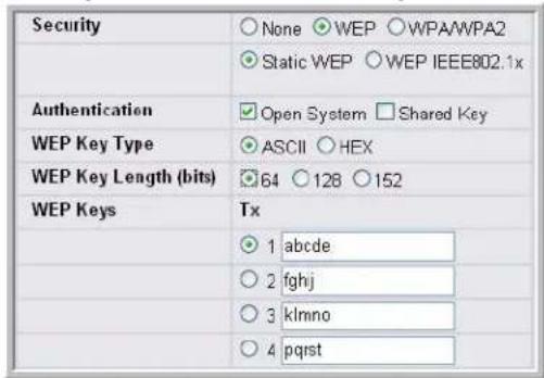
Table 16 describes the configuration options for WEP.
Table 16: Static WEP
| Field Description | |
| Static WEP or WEP IEEE 802.1X | Static WEP uses static key management. You manually configure the same keys to encrypt data on both the wireless client and the AP. Dynamic WEP (WEP IEEE 802.1X) uses dynamically generated keys to encrypt client-to-AP traffic. Dynamic WEP is more secure than Static WEP, but you need a RADIUS server to manage the keys.If you select WEP IEEE 802.1X, the screen refreshes, and there are no more fields to configure. The AP uses the global RADIUS server IP address and secret or the RADIUS server settings you specify for the VAP. The AP acts as the RADIUS client and must be configured as a client in the RADIUS serverFor information about how to configure the global RADIUS server settings on the Unified Switch, see “Configuring AAA and RADIUS Settings” on page 79. |
| Authentication Choose the authentication type:Open System—No authentication is performedShared Key—Provides a rudimentary form of user authentication, which many experts consider to be less secure than Open System since it sends the WEP key to the client in plain text.Both—Only WEP clients are authenticated. | |
| WEP Key Type Select the key type by clicking one of the radio buttons:ASCII—Includes upper and lower case alphabetic letters, the numeric digits, and special symbols such as @ and #. Spaces are not permitted.He x—Includes digits 0 to 9 and the letters A to F. | |
Table 16: Static WEP
| Field Description | |
| WEP Key Length Specify the length of the key by clicking one of the radio buttons: | |
| 6 4 b i t s | |
| 1 2 8 b i t s | |
| 1 5 2 b i t s | |
| Tx | The Transfer Key Index indicates which WEP key the access point uses to encrypt the data it transmits. To select a transfer key, click the button located between the key number and the field where you enter the key. InFigure 45, the transfer key is 3. |
| WEP Keys | You can specify up to four WEP keys. In each text box, enter a string of characters for each key. These are the RC4 WEP keys shared with the stations using the access point.Use the same number of characters for each key. The number of keys you enter depends on the Key Type and Key Length. The following list shows the number of keys to enter in the field:64 bit—ASCII: 5 characters; Hex: 10 characters128 bit—ASCII: 13 characters; Hex: 26 characters152 bit—ASCII: 16 characters; Hex: 32 charactersEach client station must be configured to use one of these same WEP keys in the same slot as specified here on the AP. |
Static WEP Rules
If you use Static WEP, the following rules apply:
- All client stations must have the Wireless LAN (WLAN) security set to WEP and all clients must have one of the WEP keys specified on the AP in order to de-code AP-to-station data transmissions.
• The AP must have all keys used by clients for station-to-AP transmit so that it can de-code the station transmissions. - The same key must occupy the same slot on all nodes (AP and clients). For example if the AP defines abc12 key as WEP key 3, then the client stations must define that same string as WEP key 3.
- Client stations can use different keys to transmit data to the access point. (Or they can all use the same key, but this is less secure because it means one station can decrypt the data being sent by another.)
- On some wireless client software, you can configure multiple WEP keys and define a client station "transfer key index", and then set the stations to encrypt the data they transmit using different keys. This ensures that neighboring APs cannot decode each other's transmissions.
- You cannot mix 64-bit, 128-bit, and 152-bit WEP keys between the access point and its client stations.
Using WPA/WPA2 Personal or Enterprise
WPA and WPA2 are Wi-Fi Alliance IEEE 802.11i standards, which include AES-CCMP and TKIP mechanisms. The WPA/WPA2 Personal employs a pre-shared key to perform an initial check of credentials. The WAP/WPA2 Enterprise uses a RADIUS server to authenticate users.
If you select WPA/WPA2 as the security mode, additional fields display, as Figure 46 shows.
Figure 46: WPA Personal Configuration
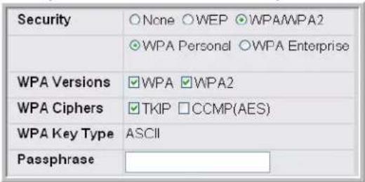
Table 17 describes the configuration options for the Static WPA security mode.
Table 17: Static WPA
| Field Description | |
| WPA Personal or WPA Enterprise | WPA/WPA2 Personal uses static key management. You manually configure the same keys to encrypt data on both the wireless client and the AP. WPA/WPA2 Enterprise uses a RADIUS server and dynamically generated keys to encrypt client-to-AP traffic. WPA Enterprise is more secure than WPA Personal, but you need a RADIUS server to manage the keys.If you select WPA Enterprise, the screen refreshes and a different set of fields appear (described later in this table). The AP uses the global RADIUS server IP address and secret or the RADIUS server settings you specify for the VAP. The AP acts as the RADIUS client and must be configured as a client in the RADIUS server.For information about how to configure the global RADIUS server settings on the Unified Switch, see “Configuring AAA and RADIUS Settings” on page 79. |
| WPA Versions Select the types of client stations you want to support:WPA. If all client stations on the network support the original WPA but none support the newer WPA2, then select WPA.WPA2. If all client stations on the network support WPA2, we suggest using WPA2 which provides the best security per the IEEE 802.11i standard.WPA and WPA2. If you have a mix of clients, some of which support WPA2 and others which support only the original WPA, select both of the boxes. This lets both WPA and WPA2 client stations associate and authenticate, but uses the more robust WPA2 for clients who support it. This WPA configuration allows more interoperability, at the expense of some security. | |
| WPA Ciphers Select the cipher suite you want to use:TKIPCCMP (AES)TKIP and CCMP (AES)Both TKIP and AES clients can associate with the access point. WPA clients must have one of the following to be able to associate with the AP:A valid TKIP keyA valid AES-CCMP key | |
| WPA Key Type Select the key type by clicking one of the radio buttons:ASCII—Includes upper and lower case alphabetic letters, the numeric digits, and special symbols such as @ and #. Spaces are not permitted.He x —Includes digits 0 to 9 and the letters A to F. | |
Table 17: Static WPA
| Field Description | |
| Passphrase | The WPA Key is the shared secret key for WPA Personal. Enter a string of at least 8 characters to a maximum of 63 characters. |
| Pre-Authentication | If you select WPA/WAP2 Enterprise, you can enable Pre-Authentication.Click thePre-Authenticationcheck box if you want WPA2 wireless clients to send pre-authentication packets. The pre-authentication information is relayed from the access point the client is currently using to the target access point.Enabling this feature can help speed up authentication for roaming clients who connect to multiple access points. Only clients that connect by using WPA2 can use this feature. It is not supported by the original WPA. |
| Pre-Authentication Limit | Enter the number of pre-authentications that can be in progress simultaneously on an AP. The limit prevents too much load on the RADIUS server. This does not prevent the pre-authentication from being attempted again when the load is lighter. A value of 0 represents no limit.Note:This field is only available if you access the network through the AP Profile or Network page underAdvanced Configuration. |
| Key Forwarding | Select the check box to allow APs to forward the Pairwise Master Key (PMK) for the wireless client to other APs in case the client roams to another AP.Note:This field is only available if you access the network through the AP Profile or Network page underAdvanced Configuration. |
| Key Caching Hold Time | Enter the amount of minutes a PMK will be held by the AP. This applies to PMKs generated by RADIUS, those that come from pre-authentication, and those that are forwarded to the AP. Note that this time limit can be overridden by RADIUS if the RADIUS server returns a longer time in the Session-Timeout attribute for a particular user. The valid values of this are from 1-1440 minutes.Note:This field is only available if you access the network through the AP Profile or Network page underAdvanced Configuration. |
Configuring Valid Access Point Settings
You can add an AP into the list of Valid APs from the Administration > Basic Setup > Valid AP tab, as Figure 47 shows, or you can add an AP from the AP Authentication Failures or Rogue AP/RF Scan lists.
From the Valid AP page, you can manually set the channel and RF signal transmit power level for an individual AP. You can also configure the AP mode and local authentication password, and you can specify which profile the AP uses.
Figure 47: Adding a Valid AP
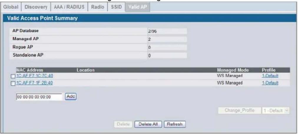
After you enter the MAC address of the AP to add to the list, click Add to add the AP to the database and to access the configuration page for the AP. For an AP that is already in the database, click the MAC address of the AP to access its configuration page.
The summary of the local AP database in terms of the number of APs of different types is displayed just above the list of the APs in the database. A popup error message is displayed when the local AP database is full. The popup message is The local AP database is full, failed to add a new AP.
Use the buttons at the bottom of the page to perform the following tasks:
- Select any AP entry in the list and click Delete to remove that AP's entry from the Valid AP Database.
- Click Delete All to clear the Valid AP database.
- Click Refresh to update the screen with the most current information.
Table 18: Valid Access Point Summary
| Field Description | |
| MAC Address | Enter the MAC address of the AP in this field. When you add the MAC address, you add the AP to the local database on the switch. |
| Location | The location of the AP. |
| Managed Mode | This field displays the current mode of the AP. You can configure the mode on the Valid Access Point Configuration page, which you access by clicking the MAC address of the AP. |
| Profile This field displays the AP profile assigned to the AP.If you have multiple AP profiles, you can assign a new profile to an AP from the summary page. Select the check box next to one or more APs, then select the new profile from the menu. Click Change Profile to apply the profile to the selected APs. | |
If you use the local database for AP validation, the switch maintains the database of access points that you validate. When you add the MAC address of an AP to the database, you can specify whether the AP is a Managed AP, Standalone AP, or
Software User Manual D-Link Unified Access System
02/15/2011
Acknowledged Rogue and assign an AP profile to the device. When the switch collects and reports information from the RF scan, it can assign the appropriate status to an AP if it is in the database.
Click on the MAC Address to navigate to the Valid Access Point Configuration page.
Figure 48: Configuring a Valid AP
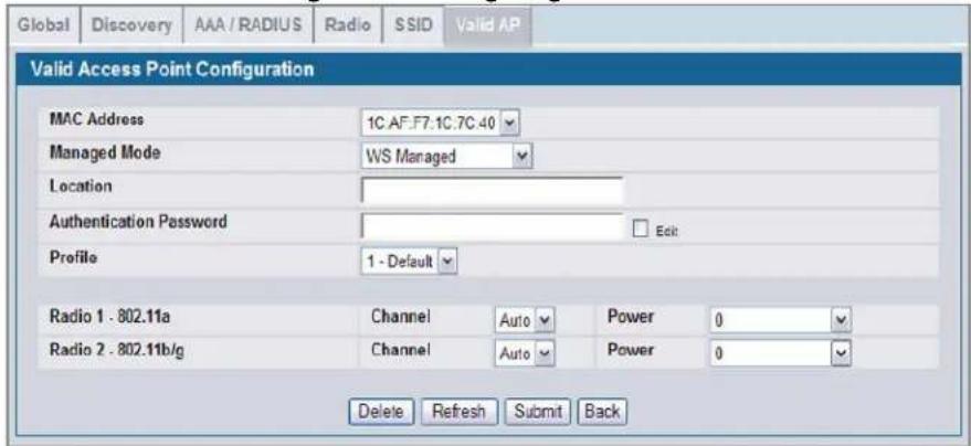
Table 19 describes the fields available on the Valid Access Point Configuration page.
Table 19: Valid AP Configuration
| Field Description | |
| MAC Address | This field shows the MAC address of the AP. To change this field, you must delete the entire Valid AP configuration and then enter the correct MAC address from the page that lists all Valid APs. |
| Managed Mode You can configure the D-Link Access Point to be in one of three modes:Standalone—The AP acts as an individual access point in the network. You do not manage the AP by using the switch. Instead, you log on to the AP itself and manage it by using the Administrator Web User Interface (UI) or CLI.WS Managed—The AP is part of the D-Link Unified Access System, and you manage it by using the D-Link Unified Switch. If an AP is in Managed Mode, the Administrator Web UI on the AP are disabled.Acknowledged Rogue—The AP has been discovered by the switch and acknowledge as a Rogue. This AP is not a D-Link Access Point. You can add an Acknowledged Rogue to the Valid AP list to prevent the Rogue from being identified as a threat. | |
| Location | To help you identify the AP, you can enter a location. This field accepts up to 32 alphanumeric characters. |
| Authentication Password | You can require the AP to authenticate itself with the switch upon discovery. If you require authentication, which is a setting on the Basic Setup > Global tab, you enter the password in this field. The password in this field must match the password configured on the AP. |
| Profile | If you configure multiple AP Profiles, you can select the profile to assign to this AP. For more information about configuring AP Profiles, see “Creating, Configuring, and Managing AP Profiles” on page 153. |
| Channel | The Channel defines the portion of the radio spectrum that the radio uses for transmitting and receiving. The range of channels and the default channel are determined by the Mode of the radio interface and the country in which the APs operate.In the United States, IEEE 802.11b/802.11g modes (802.11 b/g) support use of channels 1 through 11 inclusive, while IEEE 802.11a mode supports a larger set of non-consecutive channels (36,40,44, 48, 52, 56, 60, 64, 149, 153, 157, 161, 165).Interference can occur when multiple access points within range of each other are broadcasting on the same or overlapping channels. The impact of this interference on network performance can intensify during busy times when a large amount of data and media traffic is competing for bandwidth.If you select auto, the AP scans the RF area for occupied channels and selects a channel from the available non-interfering, or clear channels. The AP selects the best channel whenever its radio or radios restart.If you specify a channel, make sure that the channel does not interfere with the channel that neighbor APs use.Note:The channel you set for an AP in the valid AP database is fixed and takes precedence over initial channel selection done by the AP and any automatic channel planning done by the switch.Note:For radios that use 802.11a mode, some countries have a regulatory domain that requires radar detection. For these countries (based on the country code setting), the radio automatically uses the 802.11h protocol for selecting the channel if radar is detected on the statically assigned channel. |
| Power | The power level affects how far an AP broadcasts its RF signal. If the power level is too low, wireless clients will not detect the signal or experience poor WLAN performance. If the power level is too high, the RF signal might interfere with other APs within range.The default value of 0 indicates that the AP uses the power level set in the AP profile.Note:The power level you set for an AP in the valid AP database is fixed and takes precedence over any automatic power adjustments done by the AP or the switch. |
Use the buttons at the bottom of the page to perform the following tasks:
- Click Delete to delete the AP's entry from the Valid AP database.
- Click Refresh to update the screen with the most current information.
- Click Submit to update the switch with the values on the screen. If you want the switch to retain the new values across a power cycle you must perform a save.
- Click Back to see the Valid AP database summary.
Section 7: Managing and Maintaining D-Link Access Points
This chapter contains the following sections to help you manage and maintain the D-Link Access Points on your D-Link Unified Access System network:
- "Resetting the Access Points"
• "Managing Radio Frequency Settings"
• "Upgrading the Access Point Software" - "Performing Advanced Access Point Management"
For information about the commands you use to manage and maintain the APs by using the CLI, see the D-Link CLI Command Reference.
Resetting THE ACCESS POINTS
You can manually reset one or all APs from the D-Link Unified Switch. When you issue the command to reset an AP, the AP closes the SSL connection to the switch before resetting the hardware.
To reset one or more APs, click AP Management > Reset.
Figure 49: Access Point Reset
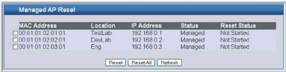
Select the APs you want to reset and click Reset, or click Reset All to reset all of the APs managed by the switch.
Click Refresh to update the screen with the most current information.
The APs might take several minutes to reset and re-establish communication with the switch. While the AP is resetting, the status changes to failed, and then back to managed once the AP is back online.
Managing Radio Frequency Settings
The radio frequency (RF) broadcast channel defines the portion of the radio spectrum that the radio on the access point uses for transmitting and receiving. The range of available channels for an access point is determined by the IEEE 802.11 mode (also referred to as band) of the access point.
The DWL-3500AP is a single-band system that operates in 802.11g mode, and the DWL-8500AP is a dual-band system that operates in 802.11a and 802.11g modes. IEEE 802.11b and 802.11g modes (802.11 b/g) operate in the 2.4 GHz RF
frequency and support use of channels 1 through 11. IEEE 802.11a mode operates in the 5 GHz frequency and supports a larger set of non-consecutive channels (36,40,44, 48, 52, 56, 60, 64, 149, 153, 157, 161, 165).

Note: The available channels depend on the country in which the APs operate. The channels described in this section are valid for the United States.
Interference can occur when multiple access points within range of each other are broadcasting on the same or overlapping channels. The impact of this interference on network performance can intensify during busy times when a large amount of data and media traffic is competing for bandwidth. For the "b/g" radio band, the classical set of non-interfering channels is 1, 6, 11. Channels 1, 4, 8, 11 produce minimal overlap. A similar set of non-interfering channels is used for the "a" radio band, which includes all channels for that mode since they are not overlapping.
Configuring Channel Plan and Power Settings
The D-Link Unified Switch software contains a channel plan algorithm that automatically determines which RF channels each D-Link Access Point should use to minimize RF interference. When you enable the channel plan algorithm, the switch periodically evaluates the operational channel on every AP it manages and changes the channel if the current channel is noisy.

Note: The regulation of radio frequencies and channel assignments varies from country to country. In countries that do not support channels 1, 6, and 11 on the 802.11b/g radio, the channel plan algorithm is inactive. For the 802.11a radio, the algorithm is inactive in countries that require 802.11h radar detection, which includes European countries and Japan.
The automatic channel selection algorithm does not affect APs that meet any of the following conditions:
- The channel is statically assigned to the AP in the RADIUS or local AP database.
• The channel has been statically assigned to the AP from the AP Management > Advanced page. - The AP uses a profile that has the Automatic Channel field disabled (Radio Configuration setting).
Additionally, radios configured to use Super A or Super G cannot use the channel plan algorithm.

Note: If the AP is not assigned a fixed channel or is not assigned a specific channel by the automatic channel selection algorithm, the AP channel selection mode is set to best. This means that the AP selects the best channel whenever the radio restarts or if the AP detects a radar signal.
The RF transmission power level affects how far an AP broadcasts its signal. If the power level is too low, wireless clients will not detect the signal or experience poor WLAN performance. If the power level is too high, the RF signal might interfere with other APs within range or broadcast the signal beyond the desired physical boundaries, which can create a security risk.
Automatic power uses a proprietary algorithm to automatically adjust the RF signal to broadcast far enough to reach wireless clients, but not so far that it interferes with RF signals broadcast by other APs.
To configure Channel Plan and Power Adjustment settings, click AP Management > RF Management.
Figure 50: RF Channel Plan and Power Configuration
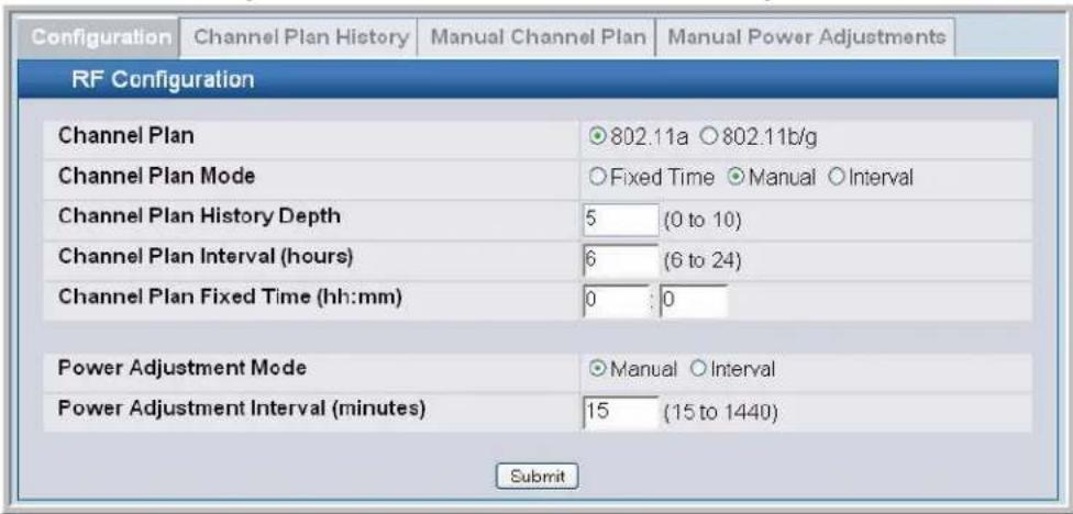
Table 20 describes the RF Channel Plan and Power Adjustment fields you can configure.

Note: When the AP changes its channel, all associated wireless clients temporarily lose their connection to the AP and must re-associate. The re-association can take several seconds, which can affect time-sensitive traffic such as voice and video.
Table 20: RF Channel Plan and Power Adjustment
| Field Description | |
| Channel Plan Before you configure channel plan settings, select the mode to configure. | |
| Channel Plan Mode | This field indicates the channel assignment mode. The mode of channel plan assignment can be one of the following:Fixed Time—If you select the fixed time channel plan mode, you specify the time for the channel plan and channel assignment. In this mode the plan is applied once every 24 hours at the specified time.Manual—With the manual channel plan mode, you control and initiate the calculation and assignment of the channel plan. You must manually run the channel plan algorithm and apply the channel plan to the APs.Interval—In the interval channel plan mode, the switch periodically calculates and applies the channel plan. You can configure the interval to be from every 6 to every 24 hours. The interval period begins when you clickSubmit. |
| Channel Plan History Depth | The channel plan history lists the channels the switch assigns each of the APs it manages after a channel plan is applied. Entries are added to the history regardless of interval, time, or channel plan mode.The number you specify in this field controls the number of iterations of the channel assignment.Note:The APs changed in previous iterations cannot be assigned new channels in the next iteration. This history prevents the same APs from being changed time after time. For example, if the history depth is set to 3, and an access point changes its channel for iteration 1, then it will not change the channel before iteration 5 of the channel adjustment algorithm (if needed). |
Table 20: RF Channel Plan and Power Adjustment
| Field Description | |
| Channel Plan Interval | If you select theIntervalchannel plan mode, you can specify the frequency at which the channel plan calculation and assignment occurs. The interval time is in hours, and you can specify an interval that ranges between every 6 hours to every 24 hours. |
| Channel Plan Fixed Time | If you select theFixed Timechannel plan mode, you can specify the time at which the channel plan calculation and assignment occurs. The channel plan calculation will occur once every 24 hours at the time you specify. |
| Power Adjustment Mode | You can set the power of the AP radio frequency transmission in the AP profile, the local database or in the RADIUS server. The power level in the AP profile is the default level for the AP, and the power will not be adjusted below the value in the AP profile.The settings in the local database and RADIUS server always override power set in the profile setting. If you manually set the power, the level is fixed and the AP will not use the automatic power adjustment algorithm.You can configure the power as a percentage of maximum power, where the maximum power is the minimum of power level allowed for the channel by the regulatory domain or the hardware capability.Manual—In this mode, you run the proposed power adjustments manually from theManual Power Adjustments page.Interval—In this mode, the switch periodically calculates the power adjustments and applies the power for all APs. The interval period begins when you clickSubmit.Note:If you set the power level in the local or RADIUS database, the settings override the power level set in the AP profile.For more information about manually setting the power level, see “Configuring Wireless Radio Settings” on page 81 and “Configuring Valid Access Point Settings” on page 101. |
| Power Adjustment Interval | This field determines how often the switch runs the power adjustment algorithm. The algorithm runs automatically only if you set the power adjustment mode toInterval. |
Click Submit to update the switch with the values on the screen. If you want the switch to retain the new values across a power cycle you must perform a save.
Viewing the Channel Plan History
The D-Link Unified Switch stores channel assignment information for the APs it manages. To access the Channel Plan History information, click the AP Management > RF Management > Channel Plan History tab.
Figure 51: Channel Plan History
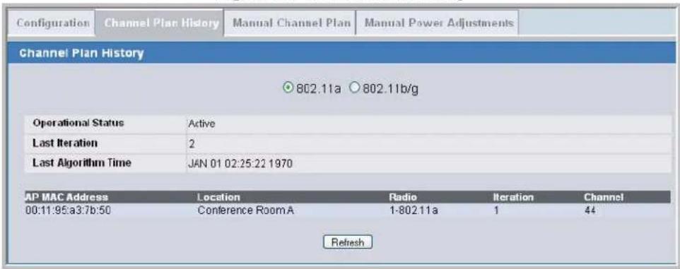
Software User Manual D-Link Unified Access System
02/15/2011
Table 21 describes the Channel Plan History fields.
Table 21: Channel Plan History
| Field Description | |
| 802.11a802.11g | The 802.11a and 802.11g radios use different channel plans, so the switch tracks the channel history separately for each radio. The channel information that displays on the page is only for the radio you select. |
| Operational Status | This field shows whether the switch is using the automatic channel adjustment algorithm on the D-Link Access Point radios. |
| Last Iteration | The number in this field indicates the last iteration of channel plan adjustments. The APs that received a channel adjustment in previous iterations cannot be assigned new channels in the next iteration to prevent the same APs from being changed time after time.On theAP Management > RF Management > Configurationtab, you can set the history depth to control the maximum number of iterations stored and displayed in the channel plan history. |
| Last Algorithm Time Shows the date and time when the channel plan algorithm last ran.NOTE: To set the system time on the switch, you must use SNTP, which is disabled by default. From the Web interface, you configure the SNTP client and server information from the LAN >Administration >SNTP Settingspage. From the CLI, use thesntpcommands in Global Config mode. | |
| AP MAC AddressLocationRadioIterationChannel | This table displays the channel assigned to an AP in an iteration of the channel plan. |
Click Refresh to update the screen with the most current information.
Initiating Manual Channel Plan Assignments
If you specify Manual as the Channel Plan Mode on the Configuration tab, the Manual Channel Plan page allows you to initiate the Channel Plan algorithm.
To manually run the channel plan adjustment feature, select the radio to update the channels on (802.11a or 802.11g) and click the Start button.
Figure 52: Manual Channel Plan
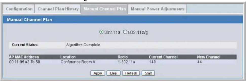
The Current Status of the plan shows one of the following states:
- None—The channel plan algorithm has not been manually run since the last switch reboot.
- Algorithm In Progress—The channel plan algorithm is running.
- Apply Complete—The algorithm and channel adjustment are complete.
- Algorithm Complete—The channel plan algorithm has finished running. A table displays to indicate proposed channel assignments. Each entry shows the AP along with the current and new channel. To accept the proposed channel change, click Apply. You must manually apply the channel plan for the proposed assignments to be applied.
- Apply In Progress—The switch is applying the proposed channel plan and adjusting the channel on the APs listed in the table.
After the channel plan runs, a table shows any APs that the algorithm recommends for new channel assignments. The current channel shows the current operating channel, and the new channel shows the proposed channel. To apply the new channels, click Apply. If no APs appear after the algorithm is complete, the algorithm does not recommend any channel changes.
Use the buttons at the bottom of the page to perform the following tasks:
- Click Clear to reset the page to the default values.
- Click Refresh to update the screen with the most current information.
It is possible for the network configuration to change between the time the automatic channel selection runs and the time you attempt to apply the proposed channel assignments.
The channel will fail to be applied to an AP if one of the following conditions exist:
• The AP has failed.
• The radio on the AP has been disabled through a profile update.
• The channel is not valid for the radio mode.
- The AP has been rebooted since the channel plan was computed and acquires a static channel that has been set statically via local database.
- The channel has been set manually through the advanced page.
- The auto-channel mode has been disabled in the profile for this AP.
Initiating Manual Power Adjustments
If you select Manual as the Power Adjustment Mode on the Configuration tab, you can manually initiate the power adjustment algorithm on the Manual Power Adjustments page.
Figure 53: Manual Power Adjustments
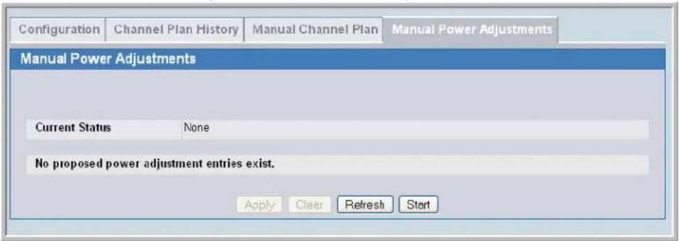
Click the Start button to manually run the power adjustment feature.
The Current Status of the plan shows one of the following states:
- None—The power adjustment algorithm has not been manually run since the last switch reboot.
- Algorithm In Progress—The power adjustment algorithm is running.
- Algorithm Complete—The power adjustment algorithm has finished running.
A table displays to indicate proposed power adjustments. Each entry shows the AP along with the current and new power levels. To accept the proposed change, click Apply. You must manually apply the power adjustment for the proposed assignments to be applied.
- Apply In Progress—The switch is adjusting the power levels that the APs use.
- Apply Complete—The algorithm and power adjustment are complete.
Use the buttons at the bottom of the page to perform the following tasks:
- Click Clear to reset the page to the default values.
- Click Refresh to update the screen with the most current information.
Upgrading the Access Point Software
The D-Link Unified Switch can upgrade software on the APs that it manages. To upgrade one or more D-Link Access Point from the switch that manages it, click the WLAN > Administration > AP Management > Software Download.
Figure 54: AP Upgrade
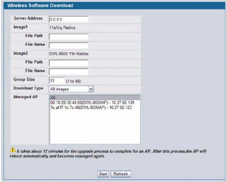

Note: The APs automatically reset after the code is successfully downloaded.
Table 22 describes the fields you must complete to upgrade D-Link Access Points.
Table 22: AP Upgrade
| Field Description | |
| Server Address | Enter the IP address of the host where the upgrade file is located. The host must have a TFTP server installed and running. |
| File Path | For image1 (11a/b/g/ radios) or image2 (DWL-8600 11n radios), enter the path to the directory where the upgrade file is located. You may enter up to 96 characters. |
| File Name | For image1 (11a/b/g/ radios) or image2 (DWL-8600 11n radios), Enter the name of the upgrade file. You may enter up to 32 characters, and the file extension “.tar” must be included. |
| Group Size | When you upgrade multiple APs, each AP contacts the TFTP server to download the upgrade file. To prevent the TFTP server from being overloaded, you can limit the number of APs to be upgraded at a time.In the Group Size field, enter the number of APs that can be upgraded at the same time. When one group completes the upgrade, the next group begins the process. |
| Download Type Select the download type. Possible options are:All imagesimage1 (802.11a/b/g) Image supported for non-11n APs (DWL-x500APs).image2 (802.11n) Image supported for 11n APs (DWL-8600AP). | |
Software User Manual D-Link Unified Access System
02/15/2011
Table 22: AP Upgrade
| Field Description | |
| Managed AP | The combination box lists the APs that the switch manages. Each AP is identified by its MAC address and location (if specified). To upgrade one or more APs, select the AP MAC address from the list. To upgrade all APs, select “All” from the top of the list. The Group Size field limits the number of simultaneous AP upgrades in order not to overwhelm the TFTP server.NOTE: We recommend that you upgrade all managed APs at the same time. |
After you provide the information about the upgrade file, click Start to begin the upgrade process. Additional fields appear to provide information about upgrade status and success.
Click Refresh to update the screen with the most current information.
The software download could be aborted while the code transfer is in progress for any AP only during the time the Abort button is displayed. It still completes the download from the TFTP server, but does not update its NVRAM. Once the NVRAM update begins for all APs involved, the Abort button disappears. An activity/progress bar is displayed during the upgrade. The activity bar is no longer displayed once the upgrade process is complete, that is, the AP is up and running and managed.
Figure 55: AP Upgrade Status.
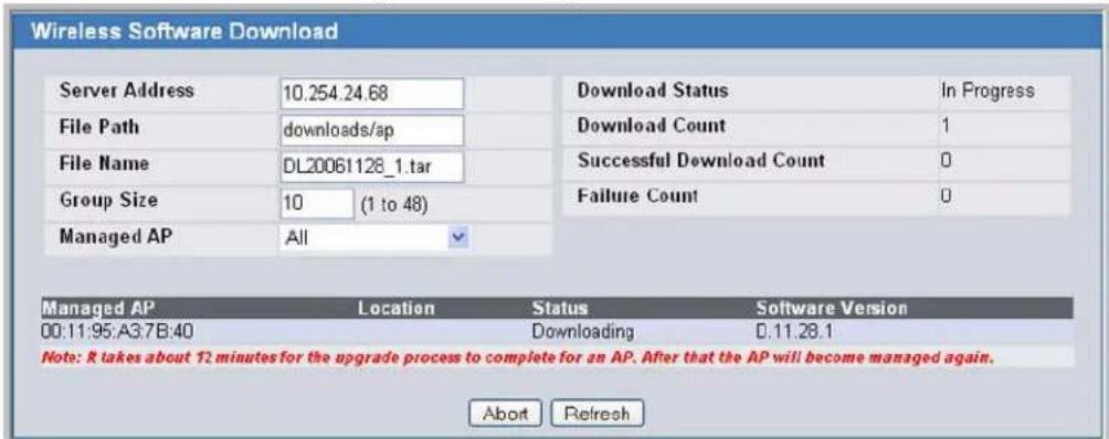
Table 23 describes the fields that appear after you start the AP upgrade process.
Table 23: AP Upgrade Status
| Field Description |
| Download Status This field shows the status of the upgrade process for all APs:Not Started—The Unified Switch has not started the download process.Requested—A request to download AP software has been made, but the switch has not done any downloads.In Progress—The AP is currently attempting to download software from the server.Success—Download completed successfully on all APs. An AP reports a successful download to the switch after the software transfers from the TFTP server to the AP and the code checksum is good. The code must also match the intended hardware platform.Failure—Download failed on all APs. A software download fails if the AP reports a software download failure due to an inability to contact the TFTP server or find the upgrade file, or if the AP loses connectivity with the switch. |
Table 23: AP Upgrade Status
| Field Description | |
| Download Count | The number in this field shows the number of managed APs to download software in the current download request. If you selected All for the managed APs to upgrade, the download count shows the number of managed APs at the time the download request was started. The value is 1 if only one AP is being updated. |
| Success Count | The number in this field shows the number of APs that have successfully downloaded the new code. This value starts with 0 at the beginning of the download and increases by one for every AP that successfully downloaded the code. |
| Failure Count | The number in this field shows the number of APs that failed to download the new code. This value starts with 0 at the beginning of the download and increases by one for every AP that failed to downloaded the code. |
A table also appears and lists each AP, its download status, and the software version it is downloading. The status for an individual AP can have one of the following values:
- Requested—Download has been requested for this AP.
- Success—The AP reported successful code download.
- Failure—The AP reported a failed code download.
- Code Transfer In Progress—The code download to the AP is in progress.
- NVRAM Update In Progress—The AP NVRAM is being updated.
- Waiting for APs to Download—The code transfer is complete, but the AP is waiting for the remaining APs to finish downloading and then it will start updating its NVRAM.
- Aborted—The upgrade of the AP was aborted.
Performing Advanced Access Point Management
When the D-Link Access Point is in Managed mode, remote access to the AP is disabled. However, you can enable Telnet access by enabling the Debug feature on the AP Management > Advanced page. From the Advanced page, you can also manually change the RF channel and power for each radio on an AP.
Figure 56: Advanced AP Management
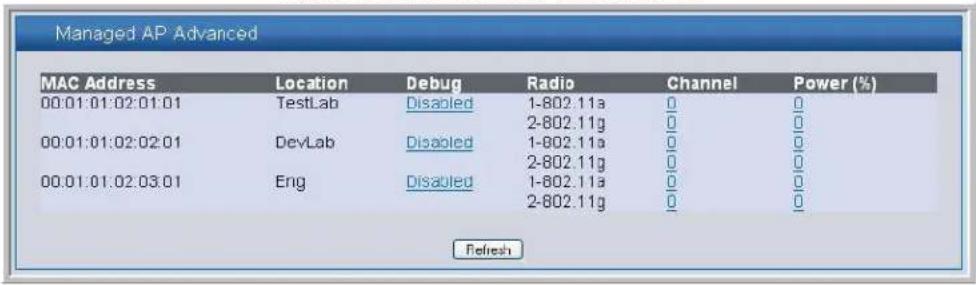
Each AP managed by the D-Link Unified Switch is listed by its MAC address and location. The location is based on the value in the RADIUS or local Valid AP database. Table 24 describes the Advanced features you can configure for the AP.
Table 24: Advanced AP Management
| Field Description | |
| Debug | To help you troubleshoot, you can enable Telnet access to the AP so that you can debug the device from the CLI.The Debug field shows the debug status and can be one of the following:DisabledSet RequestedSet in ProgressEnabledTo change the status, click theDebugstatus link. The Managed AP Debug page appears.Table 25 describes the fields on the new page. |
| Channel | Click theChannellink to access the Managed AP Channel/Power Adjust page. From that page, you can set a new channel for Radio 1 or Radio 2. The available channels depend on the radio mode and country in which the APs operate.Table 26 describes the fields on the new page. |
| Power | Click thePowerlink to access the Managed AP Channel/Power Adjust page. From that page, you can set a new power level for the AP.Table 26 describes the fields on the new page. |
Click Refresh to update the screen with the most current information.
Enabling AP Debugging
You can enable debugging on an AP to allow Telnet access to the access point. Once you Telnet to the AP, you can issue commands from the CLI to help you troubleshoot.
The fields in Table 25 appear when you click the Debug link for a managed AP on the Managed AP Advanced page.
Table 25: AP Debug
| Field Description | |
| MAC Address Shows the MAC address of the access point. | |
| Location | Shows the location of the access point, as configured in the Valid AP database. |
| IP Address Shows the IP address of the AP. | |
| Status Shows the debug status, which can be one of the following:None—Debugging has not been enabled or disabled.Set Requested—A request has been made to change the debug status.Set Complete—Debugging has been enabled or disabled. | |
| Password | Enter theadminpassword for the AP (the default is admin). |
| Confirm Password | Since the password is encrypted, you must retype the password to confirm the password. |
Table 25: AP Debug
| Field Description | |
| Enable Debug | Select or clear the Enable check box to enable or disable debugging.Once once you Telnet to the AP, you get an AP interface login prompt. The user name is admin. Enter the password you set in the previous field. The default password is admin if you did not specify a new password. From the AP CLI, you can also access the standard Linux prompt by typing the '!' character.You can issue the following debug commands at the Linux OS prompt:• get management—Display management interface information• get managed-ap—Display managed AP informationYou can issue the following debug commands at the Linux OS prompt:• ifconfig—display all interfaces.• cat /proc/meminfo—View memory utilization |
Use the buttons at the bottom of the page to perform the following tasks:
- Click Cancel to cancel changes you typed in the fields on this page.
- Click Apply to apply changes you typed in the fields on this page.
Adjusting the Channel and Power
Changes you make to the channel and power are runtime changes only. If you change the channel or power settings, the new settings are lost if the AP or switch is reset.
The fields in Table 26 appear when you click the current channel or power setting for an AP on the Managed AP Advanced page.
Table 26: Managed AP Channel/Power Adjust
| Field Description |
| AP MAC Address Shows the MAC address of the access point. |
| Radio Displays the radio and its mode. The changes apply only to this radio. |
| Channel Status The status is one of the following:NoneSet RequestedSet Complete |
Table 26: Managed AP Channel/Power Adjust
| Field Description | |
| Channel | The Channel defines the portion of the radio spectrum that the radio uses for transmitting and receiving. The range of channels and the default channel are determined by the Mode of the radio interface.IEEE 802.11b/802.11g modes (802.11 b/g) support use of channels 1 through 11 inclusive, while IEEE 802.11a mode supports a larger set of non-consecutive channels (36,40,44, 48, 52, 56, 60, 64, 149, 153, 157, 161, 165).NOTE: The available channels depend on the country in which the APs operate.NOTE: For radios that use 802.11a mode, some countries have a regulatory domain that requires radar detection. For these countries (based on the country code setting), the radio automatically uses the 802.11h protocol for selecting the channel if radar is detected on the statically assigned channel.Interference can occur when multiple access points within range of each other are broadcasting on the same or overlapping channels. The impact of this interference on network performance can intensify during busy times when a large amount of data and media traffic is competing for bandwidth.If you select auto, the AP scans the RF area for occupied channels and selects a channel from the available non-interfering, or clear channels.If you specify a channel, make sure that the channel does not interfere with the channel that neighbor APs use. |
| Power Status The status is one of the following:NoneSet RequestedSet Complete | |
| Power | The power level affects how far an AP broadcasts its RF signal. If the power level is too low, wireless clients will not detect the signal or experience poor WLAN performance. If the power level is too high, the RF signal might interfere with other APs within range. |
Use the buttons at the bottom of the page to perform the following tasks:
- Click Cancel to cancel changes selected in the menus on this page.
- Click Apply to apply changes you typed in the fields on this page.
Section 8: Monitoring Status and Statistics
This chapter contains the following sections to help you monitor the status and statistics for your D-Link Unified Access System network:
• "Monitoring Wireless Global Information"
• "Monitoring Peer Switch Status"
• "Monitoring All Access Points"
• "Monitoring Managed Access Point Status"
- "Viewing Access Point Authentication Failure Status"
- "Monitoring Rogue and RF Scan Access Points"
• "Detailed Access Point RF Scan Status"
• "Monitoring Associated Client Information"
• "Monitoring Associated Client QoS Information"
- "Viewing Client Authentication Failure Status"
• "Monitoring and Managing Ad Hoc Clients"
For information about the commands you use to view WLAN status and statistics by using the CLI, see the D-Link CLI Command Reference.
Monitoring Wireless Global Information
The D-Link Unified Switch periodically collects information from the D-Link Access Points it manages and from peer switches that are associated with it. The information on the Global page shows status and statistics about the switch and all of the objects associated with it.
You can access the global WLAN statistics by clicking Monitoring > Global.
For more information about an item on the Wireless Global Status page, click the value associated with the item to go to its status page.
Figure 57: Global WLAN Status
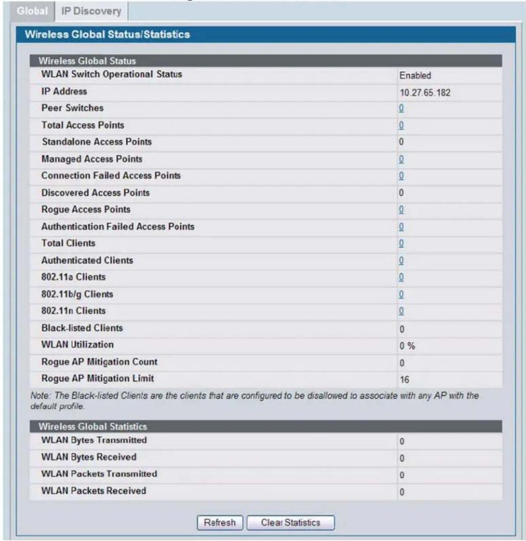
Table 27 describes the fields on the Wireless Global Status page.
Table 27: Global WLAN Statistics
| Field Description | |
| WLAN Switch Operation Status | This status field displays the operational status of the WLAN Switch. The WLAN Switch may be configured as enabled, but is operationally disabled due to configuration dependencies. If the operational status is disabled, the reason will be displayed in the following status field.The WLAN Switch is composed of multiple components, and each component in the system must acknowledge an enable or disable of the WLAN Switch. During a transition the operational status might temporarily show a pending status. |
| IP Address | IP address of the switch. For information about the switch IP address, see “Assigning the IP Address to Switches and Managed APs” on page 61. |
| Peer Switches Number of peer Unified Switches detected on the network. | |
| Field | Description |
| Total Access Points | Total number of Managed APs in the database. This value is always equal to the sum of “Managed Access Points,” “Connection Failed Access Points,” and “Discovered Access Points.” |
| Standalone Access Points | Total number of detected D-Link Access Points that are in Standalone Mode. APs in Standalone Mode are not currently managed by a D-Link Unified Switch. |
| Managed Access Points | Number of APs in the managed AP database that are authenticated, configured, and have an active connection with the Unified Switch. |
| Connection Failed Access Points | Number of APs that were previously authenticated and managed, but currently don’t have connection with the Unified Switch. |
| Discovered Access Points | APs that have a connection with the switch but have not been completely configured. This value includes all managed APs with a “Discovered” or “Authenticated” status. |
| Rogue Access Points | Number of Rogue APs currently detected on the WLAN. When an AP performs an RF scan, it might detect access points that have not been validated. It reports these APs as rogues. |
| Authentication Failed Access Points | Number of access points that failed to authenticate with the Unified Switch. |
| Total Clients | Total number of clients in the database. This total includes clients with an “Associated”, “Authenticated”, or “Disassociated” status. |
| Authenticated Clients | Total number of clients in the client database with an “Authenticated” status. |
| 802.11a Clients Shows the number of clients connected to the 802.11a radio frequency. | |
| 802.11b/g Clients | Shows the number of clients connected to the 802.11b/g radio frequency. |
| 802.11n Clients Shows the number of clients connected to the 802.11n radio frequency. | |
| Black-listed Clients | Shows the number of clients that are configured to be disallowed to associate with any AP that uses the default AP profile. |
| WLAN Utilization | Total network utilization across all APs managed by this switch. This is based on global statistics. |
| Rogue AP Mitigation Count | The number of APs to which the wireless system is currently sending de-authentication messages to mitigate against rogue APs. The range is:0 – Mitigation is not in progress.1 – 16The default is 0. |
| Rogue AP Mitigation Limit | The maximum number of APs for which the system can send de-authentication frames. The range is 16 to a value determined at compile time. The default is 16. |
| WLAN Bytes Transmitted | Total bytes transmitted across all APs managed by the switch. |
| WLAN Bytes Received | Total bytes received across all APs managed by the switch. |
| WLAN Packets Transmitted | Total packets transmitted across all APs managed by the switch. |
| WLAN Packets Received | Total packets received across all APs managed by the switch. |
Use the buttons at the bottom of the page to perform the following tasks:
- Click Refresh to update the screen with the most current information.
- Click Clear Statistics to clear all the statistics on the page.
Viewing IP Discovery Status
From the Monitoring > Global > IP Discovery tab, you can view information about communication with the devices in the IP discovery list on the Administration > Basic Setup > Discovery page.
Figure 58: Wireless Discovery Status
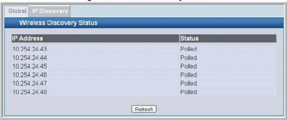
The status is in one of the following states:
- Not Polled—The switch has not attempted to contact the IP address in the L3/IP Discovery list.
- Polled —The switch has attempted to contact the IP address.
- Discovered—The switch contacted the peer switch or AP with IP address in the L3/IP Discovery list and has authenticated or validated the device.
- Discovered - Failed—The switch contacted the peer switch or AP with IP address in the L3/IP Discovery list and was unable to authenticate or validate the device.
Click Refresh to update the screen with the most current information.
If the device is an access point, an entry appears in the AP failure list with a failure reason.
For information about adding IP addresses to the IP Discovery list, see "Configuring IP Addresses of Peers and APs in the Switch" on page 66.
Monitoring Peer Switch Status
The Peer Switch page provides information about other D-Link Unified Switches in the network. To access the peer switch information, click Monitoring > Peer Switch.
Peer Unified Switches within the same peer group exchange data about themselves, their managed APs, and clients. The switch maintains a database with this data so you can view information about a peer, such as its IP address and software version. If the switch loses contact with a peer, all of the data for that peer is deleted.
Software User Manual D-Link Unified Access System
02/15/2011
Peer switches do not exchange configuration profiles or additional data about their managed APs. This means that you cannot view any other status or statistics for a managed AP from a peer switch. However, switches do use shared information for rogue AP detection.
Figure 59: Peer Switch Status

Table 28 describes the fields available on the Peer Switch Status page.
Table 28: Peer Switch Status
| Field Description | |
| IP Address IP address of the peer Unified Switch managed in the peer group. | |
| Vendor ID Vendor of the peer switch software. | |
| Software Version The software version for the given peer switch. | |
| Protocol Version Version of WS software on the peer switch. | |
| Discovery Reason | The discovery method of the given peer switch, which can be one of the following methods:• L2 Poll• IP Poll |
| Age Time since last communication with the switch in Hours, Minutes, and Seconds. | |
Click Refresh to update the screen with the most current information.
Monitoring All Access Points
The Monitoring > Access Points > All Access Points page shows summary information about managed, failed, and rogue access points the switch has discovered or detected.
Figure 60: All Access Points
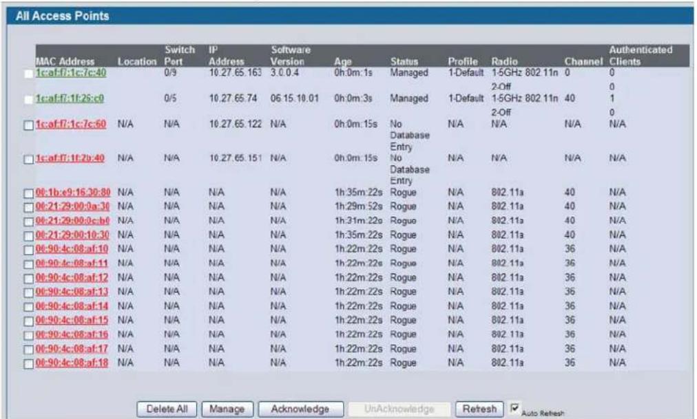
In the AP listing, a green font color indicates a Managed AP. All other APs are listed in red, regardless of their type: Failed, Rogue, or Peer Managed.
You can manually delete status entries. To clear all APs from the All Access Points status page except Managed Access Points, click Delete All.
To configure an Authentication Failed AP to be managed by the switch the next time it is discovered, select the check box next to the MAC address of the AP and click Manage. You will be presented with the Valid Access Point Configuration page. You can then configure the AP and click Submit to save the AP in the local Valid AP database. If you use a RADIUS server for AP validation, you must add the MAC address of the AP to the AP database on the RADIUS server. For more information, see Appendix B:, "Configuring the External RADIUS Server" on page 207.
To identify an AP as an Acknowledged Rogue, select the check box next to the MAC address of the AP and click Acknowledge. The switch adds the AP to the Valid AP database as an Acknowledged Rogue.
To identify an AP as a rogue (again), select the check box next to the MAC address of the acknowledged AP and click Unacknowledge. The switch deletes the AP from the Valid AP database.
Click Refresh to update the screen with the most current information.
When the Auto Refresh option is selected, the page will be refreshed after every 30 seconds.
To view additional information about the detected AP, click the MAC address of the AP.
Table 29 describes the fields on the All Access Points page.
Table 29: Monitoring All Access Points
| Field Description | |
| MAC Address Shows the MAC address of the access point. | |
| Location | A location description for the AP. This is the value configured in the valid AP database (either locally or on the RADIUS server). |
| Switch Port | The physical port (in the slot/port format) on the switch that the AP is connected to either directly or indirectly in the same L3 domain. If the AP is beyond the L3 network boundary, then 'Unknown' is displayed. |
| IP Address The network address of the access point. | |
| Software Version | Shows the version of D-Link Access Point software that the AP is running. |
| Age | Shows how much time has passed since the AP was last detected and the information was last updated. |
| Status Shows the access point status: | |
| Managed—The AP profile configuration has been applied to the AP and it's operating in managed mode.No Database Entry—The MAC address of the AP does not appear in the local or RADIUS Valid AP database.Authentication (Failed AP)—The AP failed to be authenticated by the Unified Switch or RADIUS server tiersFailed—The Unified Switch lost contact with the AP; a failed entry will remain in the managed AP database unless you remove it.Note:A managed AP will temporarily show a failed status during a reset.Rogue—The AP has not attempted to contact the switch, and the MAC address of the AP is not in the Valid AP database.Acknowledged Rogue—The AP has been acknowledged as a known rogue, and its MAC address of the AP is in the Valid AP database. | |
| Profile | The AP profile configuration currently applied to the managed AP. The profile is assigned to the AP in the valid AP database.Note:Once an AP is discovered and managed by the Unified Switch, if the profile is changed in the valid AP database (either locally or on the RADIUS server) the AP is automatically reset when a new profile is assigned. |
| Radio | Shows the wireless radio mode that each radio on the AP is using. The D-Link DWL-3500AP access point has one radio, and the D-Link DWL-8500AP access point has two radios. |
| Channel | Shows the operating channel for the radio. |
| Authenticated Clients | Shows the number of wireless clients that are associated and authenticated with the access point per radio. |

Note: Some status values for some APs in the All Access Points list are not available. Those are listed as N/A.

Note: You can sort the list of APs by any of the column heading except for Radio, Channel, and Authenticated Clients. For example, to sort the APs by the profile they use, click Profile.
MONITORING MANAGED ACCESS POINT STATUS
From the Monitoring > Access Points > Managed Access Points page, you can access a variety of information about each AP that the switch manages. The pages you access from the Status tab provide configuration and association information about managed APs and their neighbors. The pages you access from the Statistics page display information about the number of packets and bytes transmitted and received on different interfaces.
Figure 61 shows the Managed Access Point Status page with three managed APs.
Figure 61: Managed AP Status
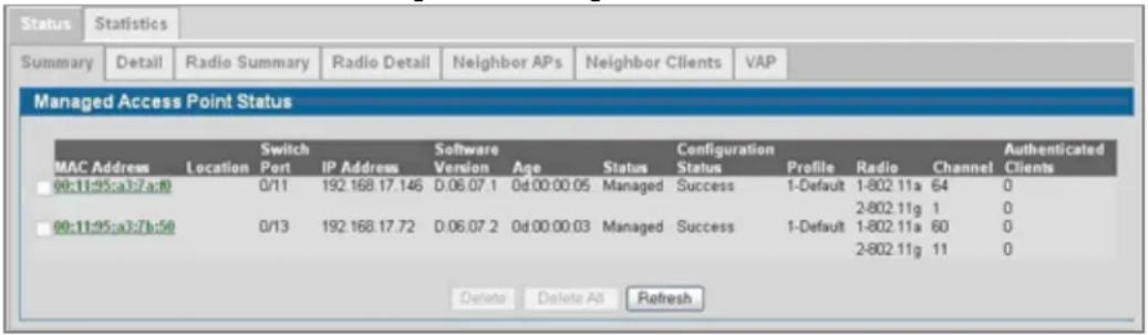
The following tabs are available from the Managed AP Status page:
• Summary—Lists the APs managed by the switch and provides summary information about them.
- Detail—Shows detailed status information collected from the AP.
• Radio Summary—Shows the channel, transmit power, and number of associated wireless clients for all managed APs.
- Radio Detail—From the Radio Summary page, click the MAC address of the AP to view detailed status for a radio interface. Use the radio button to navigate between the two radio interfaces.
- Neighbor APs—Shows the neighbor APs that the specified AP has discovered through periodic RF scans on the selected radio interface.
- Neighbor Clients—Shows information about wireless clients associated with an AP or detected by the AP radio.
- VAP—Shows summary information about the virtual access points (VAPs) for the selected AP and radio interface on the APs that the switch manages.
Table 30 describes the fields you see on the Summary page for the managed access point status.
Table 30: Managed Access Point Status
| Field Description | |
| MAC Address The Ethernet address of the Unified Switch managed AP. | |
| Location | A location description for the AP. This is the value configured in the valid AP database (either locally or on the RADIUS server). |
| Switch Port | The physical port (in the slot/port format) on the switch that the AP is connected to either directly or indirectly in the same L3 domain. If the AP is beyond the L3 network boundary, then ‘Unknown’ is displayed. |
| IP Address The network IP address of the managed AP. | |
| Software Version The software version the AP is currently running. | |
| Age Time since last communication between the WDS and the AP. | |
Table 30: Managed Access Point Status
| Field Description | |
| Status The current managed state of the AP. The possible values are:·Discovered - The AP is discovered and by the switch, but is not yet authenticated.·Authenticated - The AP has been validated and authenticated (if authentication is enabled), but it is not configured.·Managed - The AP profile configuration has been applied to the AP and it's operating in managed mode.·Failed - The Unified Switch lost contact with the AP, a failed entry will remain in the managed AP database unless you remove it.Note:A managed AP will temporarily show a failed status during a reset. | |
| Configuration Status | This status indicates if the AP is configured successfully with the assigned profile. The status is one of the following:·Not Configured - The profile has not been sent to the AP yet, the AP may be discovered but not yet authenticated.·In Progress - The switch is currently sending the AP profile configuration packet to the AP.·Success - The entire profile has been sent to the AP and there were no configuration errors.·Partial Success - The entire profile has been sent to the AP and there were configuration errors (for example, some configuration parameters were not accepted), but the AP is operational.·Failure - The profile has been sent to the AP and there were configuration errors, the AP is not operational. |
| Profile | The AP profile configuration currently applied to the managed AP, the profile is assigned to the AP in the valid AP database.Note:Once an AP is discovered and managed by the Unified Switch, if the profile is changed in the valid AP database (either locally or on the RADIUS server) the AP must be reset to configure with the new profile. |
| Radio | Shows the wireless radio mode that each radio on the AP is using. The D-Link DWL-3500AP access point has one radio, and the D-Link DWL-8500AP access point has two radios. |
| Channel Shows the operating channel for the radio. | |
| Authenticated Clients | Shows the number of wireless clients associated and associated with the access point per radio. |

Note: You can sort the list of APs by any column heading except Radio, Channel, and Authenticated Clients. For example, to sort the APs by the profile they use, click Profile.
Use the buttons at the bottom of the page to perform the following tasks:
- Select any failed AP from the list and click Delete to clear that AP from the list.
- Click Delete All to clear all the failed APs from the list.
- Click Refresh to update the screen with the most current information.
- When the Auto Refresh option is selected, the page will be refreshed after every 30 seconds.
Viewing Detailed Managed Access Point Status
To view detailed information about an AP that the switch manages, select the MAC address of the AP from the menu above the table that displays the detailed information. Click the Reset button to reset the managed AP. A pop-up asks you to confirm that you want to reset the AP. Any wireless clients associated with the access point will be disassociated. To refresh the status information for the AP, click Refresh.
Table 31 describes the fields you see on the Detail page for the managed access point status.
Table 31: Detailed Managed Access Point Status
| Field Description | |
| MAC Address - Location | The label at the top of the table shows the MAC address and location of the AP. The location is the value configured in the Valid AP database. |
| Hardware Type | Type of the AP hardware. Possible values are DWL-8500AP, DWL-8600AP, or DWL-3500AP. |
| Switch Port | The physical port (in the slot/port format) on the switch that the AP is connected to either directly or indirectly in the same L3 domain. If the AP is beyond the L3 network boundary, then ‘Unknown’ is displayed. |
| IP Address The network IP address of the managed AP. | |
| Profile | The AP profile configuration currently applied to the managed AP, the profile is assigned to the AP in the valid AP database.Note: Once an AP is discovered and managed by the Unified Switch, if the profile is changed in the valid AP database (either locally or on the RADIUS server) the AP must be reset to configure with the new profile. |
| Status The current managed state of the AP. The possible values are:Discovered - The AP is discovered and by the switch, but is not yet authenticated.Authenticated - The AP has been validated and authenticated (if authentication is enabled), but it is not configured.Managed - The AP profile configuration has been applied to the AP and it's operating in managed mode.Failure - The Unified Switch lost contact with the AP, a failed entry will remain in the managed AP database unless you remove it.Note: A managed AP will temporarily show a failed status during a reset. | |
| Discovery Reason | This status value indicates how the managed AP was discovered, the status is one of the following values:IP Poll Received - The AP was discovered via an IP poll from the Unified Switch, its IP address is configured in the IP polling list.Peer Redirect - The AP was discovered through a peer switch redirect, the AP tried to associate with another peer switch and learned the current Unified Switch IP address from the peer (peer learned Unified Switch IP address in RADIUS server response when validating the AP).Switch IP Configured - The managed AP is configured with the Unified Switch IP address.Switch IP DHCP - The managed AP learned the current Unified Switch IP address through DHCP option 43.L2 Poll Received - The AP was discovered through the D-Link Wireless Device Discovery protocol. |
| Configuration Status | This status indicates if the AP is configured successfully with the assigned profile. The status is one of the following:Not Configured - The profile has not been sent to the AP yet, the AP may be discovered but not yet authenticated.In Progress - The switch is currently sending the AP profile configuration packet to the AP.Complete Success - The entire profile has been sent to the AP and there were no configuration errors.Partial Success - The entire profile has been sent to the AP and there were configuration errors, but the AP is operational.Failure - The profile has been sent to the AP and there were configuration errors, the AP is not operational. |
| Protocol Version | Indicates the protocol version supported by the software on the AP, this is learned from the AP during discovery. |
Table 31: Detailed Managed Access Point Status
| Field Description | |
| Software Version | Indicates the version of software on the AP, this is learned from the AP during discovery. |
| Last Failing Configuration Element | If the configuration status indicates a partial success or complete failure, this field indicates the last element that failed during configuration. This field is only visible if there is a failed element. |
| Configuration Failure Error Message | If the configuration status indicates a partial success or complete failure, this field contains an ASCII string filled in by the AP containing the error message for the last failing configuration element. |
| Code Download Status | This indicates the current status of a code download request for this AP. The possible values include the following:Not Started - A code download has not been requested for the AP.Requested - A code download has been requested for the AP, the switch has not processed the request.In Progress - The switch is processing a code download request for the AP.Success - The AP has successfully downloaded the new software image.Failure - The AP failed to download the new software image. |
| Associated Clients | Total number of clients currently associated to the AP. This is the sum of all associated clients for all the VAPs enabled on the AP. Association is a transitional state. |
| Authenticated Clients | Total number of clients currently authenticated to the AP. This is the sum of all authenticated clients for all the VAPs enabled on the AP. |
| System Uptime Time in seconds since last power-on reset of the managed AP. | |
| Age Time since last communication between the WDS and the AP. | |
Use the buttons at the bottom of the page to perform the following tasks:
- Click Refresh to update the screen with the most current information.
- When the Auto Refresh option is selected, the page will be refreshed after every 30 seconds.
- Click Reset to reset the managed AP.
Viewing Managed Access Point Radio Summary Information
You can view general information about each operational radio on all APs managed by the switch. The Managed Access Point Radio Summary page shows the channel, transmit power, and number of associated wireless clients for all managed APs. For more information about a specific radio on an AP, click the radio.
Table 32 describes the fields you see on the Radio Summary page for the managed access point status.
Table 32: Managed AP Radio Summary
| Field Description | |
| MAC Address | The Ethernet address of the Unified Switch managed AP. |
| Location | A location description for the AP, this is the value configured in the valid AP database (either locally or on the RADIUS server). |
| Radio | Indicates the radio interface and configured mode of the radio, if the radio is disabled the radio mode will be displayed as Off instead of showing the configured mode. |
| Channel | If radio is operational, the current operating channel for the radio. |
| Transmit Power | If radio is operational, the current transmit power for the radio. |
Table 32: Managed AP Radio Summary
| Field Description | |
| Associated Clients | Total count of clients associated on the physical radio, this is a sum of all the clients associated to each VAP enabled on the radio. |
| Authenticated Clients | Total number of clients currently associated to the AP that have been authenticated. This is the sum of all authenticated clients for all the VAPs enabled on the radio. |
Click Refresh to update the screen with the most current information.
Viewing Detailed Managed Access Point Radio Information
You can view detailed information about each radio on the APs that the Unified Switch manages on the Radio Detail page for the managed access point radio status.
Table 33 describes the fields you see on the Radio Detail page for the managed access point status.
Table 33: Managed AP Radio Detail
| Field Description | |
| MAC Address -Location (Menu) | Shows the MAC address and location of the AP to which the values on the page apply. To view details about a different AP, select its MAC address from the menu. |
| Radio | Indicates the radio interface and configured mode of the radio, if the radio is disabled the radio mode will be displayed as Off instead of showing the configured mode. |
| Supported Channels | The list of eligible channels the AP reported to the switch for channel assignment. The list is based on country code, hardware capabilities, and any configured channel limitations. |
| Channel If radio is operational, the current operating channel for the radio. | |
| Transmit Power If radio is operational, the current transmit power for the radio. | |
| Fixed Channel Indicator | This flag indicates if a fixed channel is configured and assigned to the radio, a fixed channel can be configured in the valid AP database (locally or on a RADIUS server). |
| Manual Channel Adjustment Status | Indicates the current state of a manual request to change the channel on this radio. The valid values are:Not Started - No request has been made to change the channel.Requested - A channel change has been requested by the user but has not been processed by the switch.In Progress - The switch is processing a channel change request for this radio.Success - A channel change request is complete.Failure - A channel change request failed. |
| WLAN Utilization | Indicates the total network utilization for the physical radio, this value is based on radio statistics. |
| Authenticated Clients | Total count of clients authenticated on the physical radio, this is a sum of all the clients authenticated to each VAP enabled on the radio. |
| Fixed Power Indicator | This flag indicates if a fixed power setting is configured and assigned to the radio, a fixed transmit power can be configured in the valid AP database (locally or on a RADIUS server). |
Table 33: Managed AP Radio Detail
| Field Description | |
| Manual Power Adjustment Status | Indicates the current state of a manual request to change the power setting on this radio. The valid values are:None - No request has been made to change the power.Requested - A power adjustment has been requested by the user but has not been processed by the switch.In Progress - The switch is processing a power adjustment request for this radio.Success - A power adjustment request is complete.Failure - A power adjustment request failed. |
| Total Neighbors | Total number of neighbors (both APs and clients) that can be seen by this radio in its RF area. |
Use the buttons at the bottom of the page to perform the following tasks:
- Click Refresh to update the screen with the most current information.
- Click Back to see the Radio Summary.
Viewing Managed Access Point Neighbor APs
During the RF scan, an access point collects and stores beacon information visible from neighboring access points. Access points can store the neighbor information for up to 64 neighbor APs. If the neighbor scan information exceeds the capacity the oldest data in the neighbor list is overwritten.
- The Delete All Neighbors button clears the list. The list is repopulated as neighbors are discovered.
- Click Refresh to update the screen with the most current information.
Table 34 describes the fields you see on the Neighbor APs page for the managed access point status.
Table 34: Managed AP Neighbor Status
| Field Description | |
| MAC Address -Location (Menu) | Shows the MAC address and location of the AP to which the values on the page apply. To view details about a different AP, select its MAC address from the menu. |
| Radio (ex. 1-802.11g) | Indicates a radio interface and its configured mode. Select one of the radios to view the neighbor APs detected via an RF scan on that radio. |
| Neighbor AP MAC | The Ethernet MAC address of the neighbor AP network, this could be a physical radio interface or VAP MAC address. For D-Link Access Points this is always a VAP MAC address. The neighbor AP MAC address may be cross-referenced in the RF Scan status. |
| SSID Service Set ID of the neighbor AP network. | |
| RSSI | Received signal strength indication, this is an indicator of the signal strength relative to the neighbor and may give an idea of the neighbor's distance from the managed AP. |
| Status | Indicates the managed status of the AP, whether this is a valid AP known to the switch or a Rogue on the network. The valid values are:WS Managed - The neighbor AP is managed by this switch, the neighbor AP status can be referenced using its base MAC address.Peer WS Managed - The neighbor AP is managed by another switch within the peer group.Acknowledged Rogue - The AP is configured as a valid AP entry (local or RADIUS), it has been acknowledged and is not reported as Rogue.Ad Hoc Rogue - The AP neighbor was detected participating in an ad hoc network. |
Table 34: Managed AP Neighbor Status (Cont.)
| Field Description |
| Age Indicates the time since this AP was last reported from an RF scan on the radio. |
Viewing Clients Associated with Neighbor Access Points
The Neighbor Clients page shows information about wireless clients that have been discovered by the selected AP. D-Link Access Points can store information for up to 1024 wireless clients. If the information exceeds the capacity, the oldest data in the neighbor client list is overwritten.
- Click the Delete All Neighbors button to clear the list. The list is repopulated as neighbors and associated clients are discovered.
- Click Refresh to update the screen with the most current information.
Table 35 describes the fields you see on the Neighbor Clients page for the managed access point status.
Table 35: Neighbor AP Clients
| Field Description | |
| MAC Address -Location (Menu) | Shows the MAC address and location of the AP to which the values on the page apply. To view details about a different AP, select its MAC address from the menu. |
| Radio (ex. 1-802.11g) | Indicates a radio interface and its configured mode. Select one of the radios to view the neighbor clients detected on that radio. |
| Neighbor Client MAC The Ethernet address of client station. | |
| RSSI | Received signal strength indication, this is an indicator of the signal strength relative to the neighbor and may give an idea of the neighbor's distance from the managed AP. |
| Channel | The managed AP channel the client frame was received on, which may be different than the operating channel for this radio. |
| Discovery Reason | Indicates one or more discovery methods for the neighbor client. One or more of the following values may be displayed:RF Scan - The client was reported from an RF scan on the radio.Note:Client stations are difficult to detect via RF scan, the other methods are more common for client neighbor detection.Probe Request - The managed AP received a probe request from the client.Associated to Managed AP- This neighbor client is associated to another managed AP.Associated to This AP - The client is associated to this managed AP on the displayed radio.Associated to Peer AP - The client is associated to an AP managed by a peer switch.Ad Hoc Rogue - The client was detected as part of an Ad Hoc network. |
| Age | Indicates the time since this client was last reported from an RF scan on the radio. |
Viewing Managed Access Point VAPs
There are eight virtual access points (VAPs) available on each radio of an AP. For each radio of an access point managed by the switch, you can view a summary of the VAP configuration and the number of wireless clients associated with a particular VAP.
Table 36 describes the fields you see on the VAPs page for the managed access point status.
Table 36: Managed Access Point VAP Status
| Field Description | |
| MAC Address -Location (Menu) | Shows the MAC address and location of the AP to which the values on the page apply. To view details about a different AP, select its MAC address from the menu. |
| Radio (ex. 1-802.11g) | Indicates a radio interface and its configured mode. Select one of the radios to view VAP status for that radio. |
| VAP ID | The integer ID used to identify the VAP (0-7), this is used to uniquely identify the VAP for configuration via CLI/SNMP. |
| VAP Mode | Indicates whether or not the VAP is enabled or disabled. VAPs are always configured, but are only sending beacons and accepting clients when they are Enabled. |
| BSSID The Ethernet address of the VAP. | |
| SSID | Indicates the network assigned to the VAP. The network for each VAP is configured within the AP profile and the SSID is based on the network configuration. |
| Client Associations | Indicates the total number of clients currently associated to the VAP. |
| Client Authentications | Indicates the total number of clients currently authenticated with the VAP. |
Click Refresh to update the screen with the most current information.
Monitoring Managed AP Statistics
The managed AP statistics show information about traffic on the wired and wireless interface of the access point. This information can help diagnose network issues, such as throughput problems.
Figure 62 shows the Managed Access Point Statistics page with two managed APs.
Figure 62: Managed AP Statistics
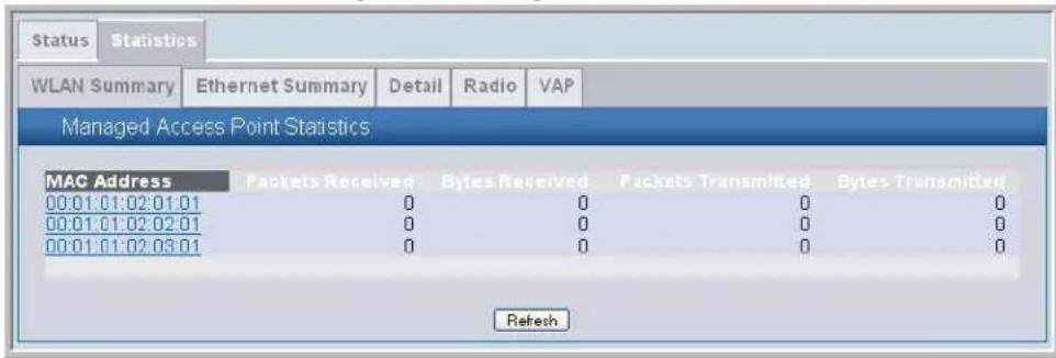
The following tabs are available from the Managed AP Statistics page:
- WLAN Summary—Shows summary information about the wireless interfaces on each AP the switch manages.
- Ethernet Summary—Shows summary information about the Ethernet (wired) interfaces on each AP the switch manages.
• D e t a i l —Shows the number and type of packets transmitted and received on a specific AP.
• Radio—Shows per-radio information about the number and type of packets transmitted and received for a specific AP. - VAP—Shows per-VAP information about the number of packets transmitted and received and the number of wireless client failures for a specific AP
On the WLAN Summary and Ethernet Summary pages, click the MAC address of the AP to view detailed statistics about the AP.
Table 37: Managed Access Point WLAN Summary Statistics
| Field Description |
| MAC Address The Ethernet address of the Unified Switch managed AP. |
| Packets Received Total packets received by the AP on the wireless network. |
| Bytes Received Total bytes received by the AP on the wireless network. |
| Packets Transmitted Total packets transmitted by the AP on the wireless network. |
| Bytes Transmitted Total bytes transmitted by the AP on the wireless network. |

Note: You can sort the list of APs by any of the column headings. For example, to sort the APs by the number of packets transmitted, click Packets Transmitted.
Click Refresh to update the screen with the most current information.
Viewing Managed Access Point Ethernet Statistics
The Ethernet summary statistics show information about the number of packets and bytes transmitted and received on the wired interface of each access point managed by the switch. The wired interface is physically connected to the LAN.
Table 38 describes the fields you see on the Ethernet Summary page for the managed access point statistics.
Table 38: Managed Access Point Ethernet Summary Statistics
| Field Description | |
| MAC Address The Ethernet address of the Unified Switch managed AP. | |
| Packets Received Total packets received by the AP on the wired network. | |
| Bytes Received Total bytes received by the AP on the wired network. | |
| Packets Transmitted Total packets transmitted by the AP on the wired network. | |
| Bytes Transmitted | Total bytes transmitted by the AP on the wired network. |
Click Refresh to update the screen with the most current information.
Viewing Detailed Managed Access Point Statistics
The detailed AP statistics show information about the packets and bytes transmitted and received on the wired and wireless interface of a particular access point managed by the switch.
Software User Manual D-Link Unified Access System
02/15/2011
Table 39 describes the fields you see on the Detail page for the managed access point statistics.
Table 39: Detailed Managed Access Point Statistics
| Field Description | |
| MAC Address -Location Menu) | Shows the MAC address and location of the AP to which the values on the page apply. To view details about a different AP, select its MAC address from the menu. |
| WLAN Packets Received Total packets received by the AP on the wireless network. | |
| WLAN Bytes Received Total bytes received by the AP on the wireless network. | |
| WLAN Packets Transmitted Total packets transmitted by the AP on the wireless network. | |
| WLAN Bytes Transmitted Total bytes transmitted by the AP on the wireless network. | |
| Ethernet Packets Received Total packets received by the AP on the wired network. | |
| Ethernet Bytes Received Total bytes received by the AP on the wired network. | |
| Ethernet Packets Transmitted Total packets transmitted by the AP on the wired network. | |
| Ethernet Bytes Transmitted Total bytes transmitted by the AP on the wired network. | |
| Multicast Packets Received Total multicast packets received by the AP on the wired network. | |
| Total Receive Errors Total receive errors detected by the AP on the wired network. | |
| Total Transmit Errors Total transmit errors detected by the AP on the wired network. | |
Click Refresh to update the screen with the most current information.
Viewing Managed Access Point Radio Statistics
The radio statistics show detailed information about the packets and bytes transmitted and received on the radio (wireless) interface of a particular access point managed by the switch.
Table 40 describes the fields you see on the Radio page for the managed access point statistics.
Table 40: Managed Access Point Radio Statistics
| Field Description | |
| MAC Address -Location (Menu) | Shows the MAC address and location of the AP to which the values on the page apply. To view details about a different AP, select its MAC address from the menu. |
| WLAN Packets Received | Total packets received by the AP on this radio interface. |
| WLAN Bytes Received Total bytes received by the AP on this radio interface. | |
| WLAN Packets Transmitted | Total packets transmitted by the AP on this radio interface. |
| WLAN Bytes Transmitted | Total bytes transmitted by the AP on this radio interface. |
| Fragments Received | Count of successfully received MPDU frames of type data or management. |
| Fragments Transmitted | Number of transmitted MPDU with an individual address or an MPDU with a multicast address of type Data or Management. |
| Multicast Frames Received | Count of MSDU frames received with the multicast bit set in the destination MAC address. |
| Multicast Frames Transmitted | Count of successfully transmitted MSDU frames where the multicast bit is set in the destination MAC address. |
| Field | Description |
| Duplicate Frame Count | Number of times a frame is received and the Sequence Control field indicates is a duplicate. |
| Failed Transmit Count | Number of times a MSDU is not transmitted successfully due to transmit attempts exceeding either the short retry limit or the long retry limit. |
| Transmit Retry Count | Number of times a MSDU is successfully transmitted after one or more retries. |
| Multiple Retry Count | Number of times a MSDU is successfully transmitted after more than one retry. |
| RTS Success Count Count of CTS frames received in response to an RTS frame. | |
| RTS Failure Count Count of CTS frames not received in response to an RTS frame. | |
| ACK Failure Count Count of ACK frames not received when expected. | |
| FCS Error Count Count of FCS errors detected in a received MPDU frame. | |
| Frames Transmitted Count of each successfully transmitted MSDU. | |
| WEP Undecryptable Count | Count of encrypted frames received and the key configuration of the transmitter indicates that the frame should not have been encrypted or that frame was discarded due to the receiving station not implementing the privacy option. |
Click Refresh to update the screen with the most current information.
Viewing Managed Access Point VAP Statistics
The VAP statistics show information about the client failures and number of packets and bytes transmitted and received on each VAP on radio one or two for a particular access point managed by the switch.
Table 41 describes the fields you see on the VAP page for the managed access point statistics.
Table 41: Managed Access Point VAP Statistics
| Field Description | |
| MAC Address -Location (Menu) | Shows the MAC address and location of the AP to which the values on the page apply. To view information about a different AP, select its MAC address from the menu. |
| Radio (ex. 1-802.11g) | Indicates a radio interface and its configured mode. Select one of the radios to view its VAP statistics. |
| VAP ID | Select one of the 8 VAPs from the menu to display its statistics. All VAPs are available regardless of whether they are enabled. |
| WLAN Packets Received | Total packets received by the AP on this VAP. |
| WLAN Bytes Received | Total bytes received by the AP on this VAP. |
| WLAN Packets Transmitted | Total packets transmitted by the AP on this VAP. |
| WLAN Bytes Transmitted | Total bytes transmitted by the AP on this VAP. |
| Client Association Failures | Number of clients that have been denied association to the VAP. |
| Client Authentication Failures | Number of clients that have failed authentication to the VAP. |
Click Refresh to update the screen with the most current information.
VIEWING ACCESS POINT AUTHENTICATION FAILURE STATUS
An AP might fail to associate to the switch due to errors such as invalid packet format or vendor ID, or because the AP is not configured as a valid AP with the correct local or RADIUS authentication information.
Status entries for failed access points are collected at a point in time and eventually age out. The age value for each entry shows how long ago the switch recorded the entry. You can configure the age out time for status entries on the Administration > Advanced Configuration > Global page. You can also manually delete status entries.
To view a list of APs that failed to associate with the D-Link Unified Switch, click Monitoring > Access Points > Authentication Failed Access Points.
Figure 63: Authentication Failed AP Status
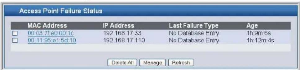
The AP authentication failure list shows information about APs that failed to establish communication with the D-Link Unified Switch. The AP can fail due to one of the following reasons:
- No Database Entry—The MAC address of the AP is not in the local Valid AP database or the external RADIUS server database, so the AP has not been validated.
- Authentication—The authentication password configured in the AP did not match the password configured in the local database or RADIUS database.
Use the buttons at the bottom of the page to perform the following tasks:
• To delete the entries for all APs from the failure list, click Delete All.
- To configure an Authentication Failed AP to be managed by the switch the next time it is discovered, select the check box next to the MAC address of the AP and click Manage.
- You will be presented with the Valid Access Point Configuration page. You can then configure the AP and click Submit to save the AP in the local Valid AP database.
- Click Back to see a list of Authentication Failed Access Points.
- Click Refresh to update the screen with the most current information.
- When the Auto Refresh option is selected, the page will be refreshed after every 30 seconds.
If you use a RADIUS server for AP validation, you must add the MAC address of the AP to the RADIUS server database. For more information, see Appendix B: "Configuring the External RADIUS Server" on page 207.
Click the MAC address of the AP to view more information about the AP. If the AP is not a D-Link Access Point, some values are unknown.
To view additional data (beacon information) for an AP in the failure list, you can search for the MAC address of the failed AP on the Rogue/RF Scan page. However, some APs that attempt to contact the switch on the wired network might not be detected during the RF scan.
Table 42: Access Point Authentication Failure Status
| Field Description | |
| MAC Address The Ethernet address of the AP. | |
| IP Address The network IP address of the AP. | |
| Last Failure Type Indicates the last type of failure that occurred. | |
| Vendor ID Vendor of the AP software. | |
| Validation Failures The count of association failures for this AP. | |
| Authentication Failures The count of authentication failures for this AP. | |
| Protocol Version Indicates the protocol version supported by the software on the AP. | |
| Software Version | Indicates the version of software on the AP. |
| Hardware Type | Hardware platform for the AP. |
| Age | Time in seconds since failure occurred. |
- Click Back to see a list of Authentication Failed Access Points.
- Click Refresh to update the screen with the most current information.
Monitoring Rogue and RF Scan Access Points
The radios on each D-Link Access Point can periodically scan the radio frequency to collect information about other APs and wireless clients that are within range. In normal operating mode the AP always scans on the operational channel for the radio. Two other scan modes are available for each radio on the APs:
- Scan Other Channels—Configures the AP to periodically leave its operational channel and scan other channels within that frequency.
- Scan Sentry—Disables normal operation of the radio and performs a continuous radio scan. In this mode, no beacons are sent, and no clients are allowed to associate with the AP.
When Scan Other Channels or Scan Sentry modes are enabled, the AP scans all available channels on each radio. When the scan is complete, the AP sends information it collected during the RF scan to the switch that manages it. For information about how to configure the scan mode, see "Configuring Wireless Radio Settings" on page 81.
The D-Link Unified Switch considers an access point to be a Rogue if is detected during the RF scan process and the MAC address of the detected AP is not in the local or RADIUS Valid AP database or if the AP is not managed by a peer switch.
To start mitigation on any Rogue Access Point, select the checkbox of the AP and click Add to Attack List.
From the Monitoring > Access Points > Rogue/RF Scan Access Points page, you can view information about all APs detected via RF scan, including those reported as Rogues.
You can sort the APs in the list based any of the column headings. For example, to group all Rogue APs together, click Status.

Note: You cannot sort the list in the Under Mitigation column.
Status entries in the RF Scan list are collected at a point in time and eventually age out. The age value for each entry shows how long ago the switch recorded the entry. You can configure the age out time for status entries on the Administration > Advanced Configuration > Global page. You can also manually delete status entries. To clear all APs from the RF scan list, click Delete All.
To configure a Rogue AP to be managed by the switch the next time it is discovered, select the check box next to the MAC address of a detected AP and click Manage. You will be presented with the Valid Access Point Configuration page. You can then configure the AP and click Submit to save the AP in the local Valid AP database. If you use a RADIUS server for AP validation, you must add the MAC address of the AP to the AP database on the RADIUS server. For more information, see Appendix B: "Configuring the External RADIUS Server" on page 207.
Figure 64: RF Scan
| MAC Address | SSIO | Physical Mode | Channel | Status | Age |
| 00:00:bc:00:12:50 | ST-WS-AP5g | 802.11a | 64 | Rogue | 0d:01:15:54 |
| 00:02:bc:00:12:50 | Broadcom VAP | 802.11g | 1 | Rogue | 0d:02:56:14 |
| 00:02:bc:00:12:50 | ST-WS-AP3a | 802.11a | 161 | Rogue | 0d:00:00:23 |
| 00:02:bc:00:12:80 | ST-WS-AP4a | 802.11a | 161 | Rogue | 0d:00:00:23 |
| 00:02:bc:00:12:a8 | ST-WS-AP2g | 802.11a | 64 | Rogue | 0d:01:31:23 |
| 00:02:bc:00:12:b0 | ST-WS-AP2a | 802.11a | 161 | Acknowledged Rogue | 0d:00:00:23 |
| 00:02:bc:00:13:10 | Metrics-Test | 802.11a | 56 | Rogue | 0d:00:58:24 |
| 00:02:bc:00:13:70 | Metrics-Test | 802.11a | 153 | Rogue | 0d:01:41:31 |
| 00:02:bc:00:13:a0 | Metrics-Test | 802.11a | 153 | Rogue | 0d:01:12:58 |
| 00:02:bc:00:13:b8 | Metrics-Test | 802.11a | 56 | Rogue | 0d:00 21:54 |
| 00:02:bc:00:14:30 | Metrics-Test | 802.11a | 56 | Rogue | 0d:00 01:53 |
| 00:02:bc:00:14:50 | Metrics-Test | 802.11a | 56 | Rogue | 0d:00 21:54 |
| 00:02:bc:00:14:90 | Metrics-Test | 802.11a | 56 | Rogue | 0d: 01 : 26 : 58 |
| 00:02:bc:00:14:a8 | Metrics-Test | 802.11a | 153 | Rogue | 0d 00 15 : 53 |
| O_D O_D O_D O_D O_D O_D O_D O_D O_D O_D O_D O_D O_D O_D O_D O_D O_D O_D O_D O_D O_D^* |
To identify an AP as an acknowledge rogue, select the check box next to the MAC address of the AP and click Acknowledge. The switch adds the AP to the Valid AP database as an Acknowledged Rogue. To identify an AP as a rogue (again), select the check box next to the MAC address of the acknowledged AP and click Unacknowledge. The switch deletes the AP from the Valid AP database.
- Click Refresh to update the screen with the most current information.
- When the Auto Refresh option is selected, the page will be refreshed after every 30 seconds.
When you manage or acknowledge a rogue AP, the switch adds an entry to the valid AP database but does not change the entry on the RF Scan Status page. However, the next time the switch discovers the AP, its entry in the RF Scan Status list will be handled based on the change.
To view additional information about the detected AP, click the MAC address of the AP. Click Back to see the list of Rogue/RF Scan Access Points.
DETAILED ACCESS POINT RF SCAN STATUS
The detailed status for access points detected during the RF scan shows the information on the summary page plus some additional information learned from the beacon frame, such as transmission rate.
The following table shows the information the Access Point RF Scan Status page shows for an individual access point.
Table 43: Access Point RF Scan Status
| Field Description | |
| MAC Address | The Ethernet MAC address of the detected AP, this could be a physical radio interface or VAP MAC. For D-Link Access Points this is always a VAP MAC address. |
| SSID Service Set ID of the network, this is broadcast in detected beacon frame. | |
| Physical Mode Indicates the 802.11 mode being used on the AP. | |
| Channel Transmit channel of the AP. | |
| Status | Indicates the managed status of the AP, whether this is a valid AP known to the switch or a Rogue on the network. The valid values are:WS Managed - The neighbor AP is managed by this switch, the neighbor AP status can be referenced using its base MAC address.Peer WS Managed - The neighbor AP is managed by another switch within the peer group.Acknowledged Rogue - The AP is configured as a valid AP entry (local or RADIUS), it has been acknowledged and is not reported as Rogue.Ad Hoc Rogue - The AP neighbor was detected participating in an ad hoc network. |
| Transmit Rate Indicates the rate at which the AP is currently transmitting data. | |
| Beacon Interval Beacon interval for the neighbor AP network. | |
| Discovered Age Time in seconds since this AP was first detected in an RF scan. | |
| Age Time in seconds since this AP was last detected in an RF scan. | |
- Click Refresh to update the screen with the most current information.
- Click Back to return to the list of Rogue/RF Scan Access Points.
Monitoring WIDS AP De-Authentication Attack Status
The basic technique employed by the wireless system for automatically protecting the network against rogue APs is to send de-authentication messages to clients by faking the rogue AP MAC address as the source MAC and BSSID of the de-authentication frame and using the broadcast MAC address as the destination of the de-authentication packet. The de-authentication attack feature must be globally enabled in order for the wireless system to do this function. The administrator must insure that no legitimate APs are classified as rogues before enabling the attack feature. The de-authentication attack feature is disabled by default. To enable the de-authentication attack feature, use the AP De-Authentication Attack configuration parameter on the WLAN > Basic Setup > Global > Wireless Global Configuration page. See Table 4: "Basic Wireless Global Configuration," on page 54. The AP De-Authentication Attack configuration parameter persists across a switch reboot if the setting is saved in the configuration.
The wireless system can conduct the de-authentication attack against up to 16 APs at the same time. The intent of this attack is to serve as a temporary measure until the rogue AP is located and disabled.
The wireless switch maintains a list of BSSIDs against which it is conducting a de-authentication attack. The switch sends the list of BSSIDs and channels on which the rogue APs are operating to every managed AP.
Both sentry radios and operational-mode radios participate in the de-authentication attack. The sentry radios send de-authentication messages whenever they are tuned to the appropriate channel during the RF scan. If the sentry radio is not configured to scan the band where the rogue is operating, then it never sends de-authentication message to that rogue.
The operational mode radios send de-authentication frames only to rogue APs that operate on the same channel as the managed AP radio. The messages are sent every 10 seconds. For instance if five BSSIDs in the attack list are on the same channel as the operational mode radio, then the radio sends a burst of five de-authentication frames, one for each BSSID, every 10 seconds. The attack interval is communicated by the switch to the AP, but is not configurable by the administrator and is set to 10 seconds.
The switch sends the attack list to all new APs that connect to the managed network. The switch also sends the attack list every time the list changes. The whole list and the number of rogue BSSIDs in the list are sent every time. If there is no attack in progress, then the number of BSSIDs is zero.
The BSSIDs are added to the attack list by the administrator through the switch Web UI. When a rogue AP is acknowledged by the administrator or the rogue RF Scan entry is deleted from the RF Scan database, the BSSID is removed from the attack list.
The RF Scan entry for detected APs indicates whether a de-authentication attack is in progress against this AP. This is indicated by the status of that AP as Rogue – Under Mitigation on the WLAN > Monitoring > Access Point > Rogue/RF Scan Access Points page. See “Monitoring Rogue and RF Scan Access Points” on page 138.
The Rogue AP Mitigation Count and Rogue AP Mitigation Limit parameters contain global information about the Rogue AP Mitigation. These status parameters are displayed on the WLAN > Monitoring > Global web page. See Table 27: "Global WLAN Statistics," on page 120.
To view information about APs under mitigation, the parameters listed below are displayed for each AP on the WLAN >Monitoring >Access Point >AP De-Authentication Attack Status page. On the web page, the MAC addresses provide a link to the RF Scan database.
Figure 65: AP De-Authentication Attack Status

Table 44: AP De-Authentication Attack Status
| Field Description | |
| BSSID | BSSID of the AP against which the attack is launched. The range is MAC Address. |
| Channel The channel on which the rogue AP is operating. The range is 1-161. | |
| Time Since Attack Launched The time since the attack started on this AP. The range is the time stamp. | |
| Age The time since the RF Scan report about this AP. The range is the time stamp. | |
Click Refresh to update the screen with the most current information.
Monitoring Associated Client Information
You can view a variety of information about the wireless clients that are associated with the APs the switch manages. To access the associated client information, click Monitoring > Client > Associated Clients.
Figure 66: Associated Client Status
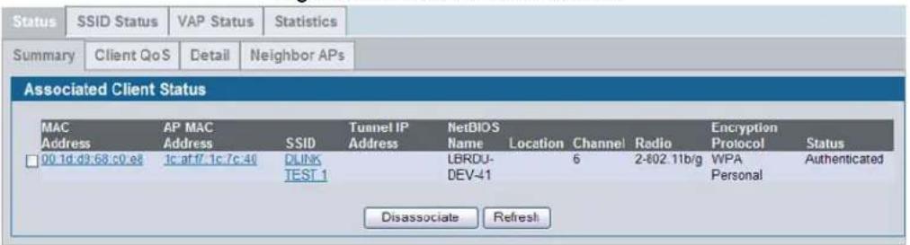
The following tabs are available:
- Status—Shows status information about wireless clients that are associated with APs managed by the switch and contains the following information:
- Summary—Shows basic information about associated clients.
- Client QoS—Shows Associated Client QoS status.
- Detail—Shows more detailed information about associated clients, such as which VLAN the client is assigned to and how long the client has been inactive.
- Neighbor APs—Shows the managed APs that are within range of the wireless clients, which can help you determine the managed AP an associated client might use for roaming.
• SSID Status—Shows the SSID and client MAC address of all clients connected to specific networks.
• V A P S t a t u s —Shows the clients associated with a specific VAP on a D-Link Access Point
• Statistics—Shows statistics about wireless clients that are associated with APs managed by the switch and contains the following information:
- Association Summary—Shows the statistics for a wireless client while it is associated with a single AP.
- Session Summary—If a wireless client roams among different managed APs, the switch can track the statistics for the entire session.
- Association Detail—Shows additional information about packets the associated client transmits and receives during association with a single managed AP.
- Session Detail—Shows additional information about packets the associated client transmits and receives during a session, which can include statistics for one or more managed AP associations if the client has roamed.
Since the associated client database supports roaming across APs, an entry is not removed when a client disassociates from a specific AP. After a client has disassociated the entry is deleted after the client times out. You configure the timeout value in the Client Roam Timeout field on the WLAN > Administration > Advanced Configuration > Global page. The timeout value corresponds to the time allowed for roaming to another managed AP.
Viewing Associated Client Status
Table 45 describes the information available on the Summary page for the associated client status.
Table 45: Associated Client Status Summary
| Field Description | |
| MAC Address The Ethernet address of client station. | |
| AP MAC Address The Ethernet MAC address of the AP that the client is associated with. | |
| SSID Indicates the network on which the client is connected. | |
| Tunnel IP Address | If the client is using an L3 Tunnel, this field shows the IP address of the client. Otherwise, this field is blank. |
| NetBIOS Name | A unique 16-byte identifier that NetBIOS services use to identify resources on a network. |
| Location | The location of the AP that the client is associated with. The AP location is configured in the Valid AP database. |
| Channel | Indicates the operating channel for the client association. |
| Radio | The mode of the radio that the wireless client is using. |
| Encryption Protocol | The security that the wireless client is using to connect to the WLAN. |
| Status | Indicates whether or not the client has associated and/or authenticated. The valid values are:Associated - The client is current associated to the managed AP.Authenticated - The client is currently associated and authenticated to the managed AP.Disassociated - The client has disassociated from the managed AP, if the client does not roam to another managed AP within the client roam timeout, it will be deleted. |
- Click Disassociate to disassociate the client from the AP it is associated with.
- Click Refresh to update the screen with the most current information.
Monitoring Associated Client QoS Information
Client-based Rate Limiting relies on 802.1X authentication and RADIUS to establish bi-directional maximum rate limits for wireless clients. A client authentication record, as identified by username and password, contains vendor-specific attributes
WISPr-Bandwidth-Max-Up and WISPr-Bandwidth-Max-Down that are used by 802.1X-authenticated wireless clients to supply the necessary rate limiting information to the AP.
Similar bandwidth maximum up and down rate limit parameters are included in the wireless network configuration to be used for clients without valid RADIUS attributes of their own. These values are not enforced for the network as a whole, but are defined as per-client defaults. A Rate Limiting global configuration parameter provides the master control for AP Client rate limit enforcement of wireless clients.
The Rate Limiting operation occurs in either managed or standalone mode. A WS-managed AP receives its QoS configuration from the WS and proceeds to set up the necessary facilities in the AP software. A standalone AP uses its own user interface (Web, CLI) or SNMP MIB to configure similar AP Client QoS parameters as the WS in order to perform comparable AP software operation.
For RADIUS exchanges, the AP acts as a Network Authentication Server (NAS). The two new RADIUS attributes defined for rate limiting, WISPr-Bandwidth-Max-Up and WISPr-Bandwidth-Max-Down are described below in Table 46.
To access the associated client QoS information, click Monitoring > Client > Associated Clients > Status tab > Client QoS.
Figure 67: Associated Client QoS Status
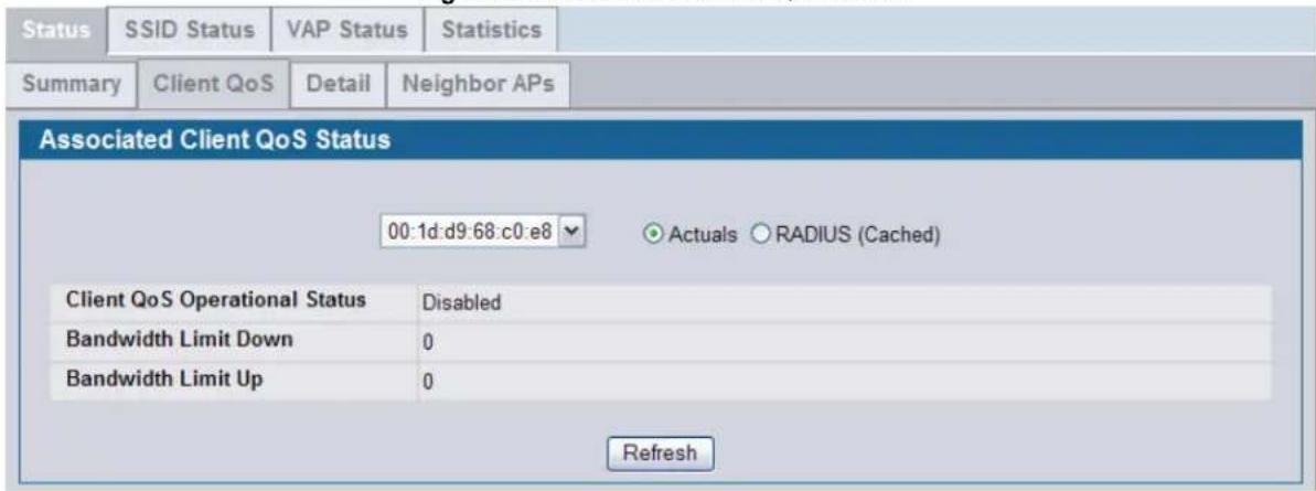
Table 47 describes the information available on the Associated Client QoS Status page.
Table 46: Associated Client QoS Status
| Field Description | |
| MAC Address The Ethernet address of client station. | |
| ActualsRADIUS (Cached) | Use the selector to determine the source of the information the page displays:Select Actuals to display the actual status parameters configured on the AP.Select RADIUS (Cached) to display any client QoS parameters that were obtained for the client from a RADIUS server when using 802.1X authentication. |
| Client QoS Operational Status Displays whether QoS is enforced for the client. | |
Table 46: Associated Client QoS Status
| Field | Description |
| Bandwidth Limit Down Shows the maximum rate at which the client receives traffic from the AP in bits per second. The rate shown in this field is the configured value rounded down to the nearest 64 kbps. A value of 0 means no bandwidth limiting is in effect in this direction. | |
| Bandwidth Limit Up Shows the maximum rate at which the client transmits traffic to the AP in bits per second. The rate shown in this field is the configured value rounded down to the nearest 64 kbps. A value of 0 means no bandwidth limiting is in effect in this direction. | |
- Click Refresh to update the screen with the most current information.
Viewing Detailed Associated Client Status
For each client associated with an AP that the switch manages, you can view detailed status information about the client and its association with the access point.
Table 47 describes the information available on the Detail page for the associated client status.
Table 47: Detailed Associated Client Status
| Field Description | |
| MAC Address | The Ethernet address of client station. To view details about a different client, select its MAC address from the menu. |
| SSID Indicates the network on which the client is connected. | |
| AP MAC Address MAC address of the AP to which this client is associated. | |
| BSSID | Indicates the Ethernet MAC address for the managed AP VAP where this client is associated. |
| Location Location of the AP to which this client is associated. | |
| Status | Indicates whether or not the client has associated and/or authenticated. The valid values are:• Associated - The client is current associated to the managed AP.• Authenticated - The client is currently associated and authenticated to the managed AP.• Disassociated - The client has disassociated from the managed AP, if the client does not roam to another managed AP within the client roam timeout, it will be deleted. |
| Radio Indicates the radio on which the client is associated. | |
| Channel | Indicates the operating channel for the client association. |
| VLAN | If client is on a VAP using VLAN data forwarding mode, indicates the current assigned VLAN. |
| User Name | Indicates the user name of client that have authenticated via 802.1X, clients on networks with other security modes will not have a user name. |
| Transmit Data Rate | Indicates the rate at which the client station is currently transmitting data. |
| Inactive Period | For current association, period of time that the AP has not seen any traffic for the client. |
| Age | Indicates the time in seconds since the switch has received new association data for this client. |
| NetBIOS Name | A unique 16-byte identifier that NetBIOS services use to identify resources on a network. |
| Tunnel IP Address | This field is blank for all non-tunneled clients. For a tunneled client, this is the assigned tunnel IP address. |
Table 47: Detailed Associated Client Status
| Field Description | |
| Captive Portal | This field appears only if the wireless client has accessed the network through a captive portal and has been authenticated by the switch.To view additional information about the client’s captive portal connection, click “Authenticated,” which links to the detailed client information accessible from the Captive Portal > Client Connection Status page. |
- Click Disassociate to disassociate the selected associated client.
- Click Refresh to update the screen with the most current information.
Viewing Associated Client Neighbor AP Status
The Neighbor AP page for the associated client status shows information about access points that the client detects. The information on this page can help you determine the managed AP an associated client might use for roaming.
Table 48 describes the information available on the Neighbor AP page for the associated client status.
Table 48: Associated Client Neighbor AP Status
| Field Description | |
| MAC Address (Menu) | Shows the MAC address of the client to which the values on the page apply. To view details about a different associated client, select its MAC address from the menu. |
| AP MAC Address The base Ethernet address of the Unified Switch-managed AP. | |
| Location The configured descriptive location for the managed AP | |
| Radio | The radio interface and its configured mode that detected this client as a neighbor. |
| Discovery Reason | Indicates one or more discovery methods for the neighbor client. One or more of the following values may be displayed:RF Scan - The client was reported from an RF scan on the radio.Note:Client stations are difficult to detect via RF scan, the other methods are more common for client neighbor detection.Probe Request - The managed AP received a probe request from the client.Associated to Managed AP- This neighbor client is associated to another managed AP.Associated to this AP - The client is associated to this managed AP on the displayed radio.Associated to Peer AP - The client is associated to an AP managed by a peer switch.Ad Hoc Rogue - The client was detected as part of an ad hoc network with this AP. |
Click Refresh to update the screen with the most current information.
Viewing Associated Client SSID Status
Each managed AP can have up to 16 different networks that each have a unique SSID. Although several wireless clients might be connected to the same physical AP, they might not connect by using the same SSID. The SSID Status page lists the SSIDs of the networks that each wireless client associated with a managed AP has used for WLAN access.
Table 49: Associated Client SSID Status
| Field Description | |
| SSID Indicates the network on which the client is connected. | |
| MAC Address The Ethernet address of client station. | |
| Channel Indicates the operating channel for the client association. | |
| Status | Indicates whether or not the client has associated and/or authenticated. The valid values are:• Associated - The client is current associated to the managed AP.• Authenticated - The client is currently associated and authenticated to the managed AP.• Disassociated - The client has disassociated from the managed AP, if the client does not roam to another managed AP within the client roam timeout, it will be deleted. |
Click Refresh to update the screen with the most current information.
Viewing Associated Client VAP Status
Each AP has 8 Virtual Access Points (VAPs) per radio, and every VAP has a unique MAC address (BSSID). The VAP Associated Client Status page shows information about the VAPs on the managed AP that have associated wireless clients.
Table 50: Associated Client VAP Status
| Field Description | |
| BSSID | Indicates the Ethernet MAC address for the managed AP VAP where this client is associated. |
| SSID The SSID the client is using to connect to the WLAN. | |
| AP MAC Address | This field indicates the base AP Ethernet MAC address for the managed AP. |
| Location The descriptive location configured for the managed AP. | |
| Radio | Displays the managed AP radio interface the client is associated to and its configured mode. |
| Client MAC Address The Ethernet address of client station. | |
| Tunnel IP Address | If the client is using an L3 Tunnel, this field shows the IP address of the client. Otherwise, this field is blank. |
Click Refresh to update the screen with the most current information.
Viewing Associated Client Statistics
A wireless client can roam among APs without interruption in WLAN service. The D-Link Unified Switch tracks the traffic the client sends and receives during the entire wireless session while the client roams among APs that the switch manages. The switch stores statistics about client traffic while it is associated with a single AP as well as throughout the roaming session.
The statistics on the Association Summary page show information about the traffic a wireless client receives and transmits while it is associated with a single AP.
Table 51: Associated Client Association Summary Statistics
| Field | Description |
| MAC Address | The Ethernet address of client station. |
Table 51: Associated Client Association Summary Statistics
| Field Description |
| Packets Received Packets received from the client station. |
| Bytes Received Bytes received from the client station. |
| Packets Transmitted Packets transmitted to the client station. |
| Bytes Transmitted Bytes transmitted to the client station. |
Click Refresh to update the screen with the most current information.
The statistics on the Session Summary page show information about the traffic a wireless client receives and transmits while it is connected to the same WLAN network shared by APs that the switch manages.
If the client roams from one AP to another AP but remains connected to the same network, the session continues and the session statistics continue to accumulate. If the client closes the wireless connection or roams out of the range of an AP managed by the switch, the session ends.
Table 52: Associated Client Summary Statistics
| Field Description |
| MAC Address The Ethernet address of client station. |
| Packets Received Packets received from the client station. |
| Bytes Received Total bytes received from the client station. |
| Packets Transmitted Total packets transmitted to the client station. |
| Bytes Transmitted Total bytes transmitted to the client station. |
Click Refresh to update the screen with the most current information.
The statistics on the Association Detail page show information about the traffic a wireless client receives and transmits while it is associated with a single AP.
Table 53: Associated Client Association Detail Statistics
| Field Description | |
| MAC Address (Menu) | Shows the MAC address of the client to which the values on the page apply. To view details about a different associated client, select its MAC address from the menu. |
| Packets Received Total packets received from the client station. | |
| Bytes Received Total bytes received from the client station. | |
| Packets Transmitted Total packets transmitted to the client station. | |
| Bytes Transmitted Total bytes transmitted to the client station. | |
| Fragments Received Total fragmented packets received from the client station. | |
| Fragments Transmitted Total fragmented packets transmitted to the client station. | |
| Transmit Retries | Number of times transmits to client station succeeded after one or more retries. |
| Transmit Retries Failed | Number of times transmits to client station failed after one or more retries. |
Table 53: Associated Client Association Detail Statistics
| Field Description |
| Duplicates Received Total duplicate packets received from the client station. |
- Click Refresh to update the screen with the most current information.
- Click Back to see the Association Summary.
The statistics on the Session Detail page show information about the traffic a wireless client receives and transmits while it is connected to the same WLAN network shared by APs that the switch manages.
Table 54: Associated Client Session Detail Statistics
| Field Description | |
| MAC Address (Menu) | Shows the MAC address of the client to which the values on the page apply. To view details about a different associated client, select its MAC address from the menu. |
| Packets Received Total packets received from the client station. | |
| Bytes Received Total bytes received from the client station. | |
| Packets Transmitted Total packets transmitted to the client station. | |
| Bytes Transmitted Total bytes transmitted to the client station. | |
| Fragments Received Total fragmented packets received from the client station. | |
| Fragments Transmitted Total fragmented packets transmitted to the client station. | |
| Transmit Retries | Number of times transmits to client station succeeded after one or more retries. |
| Transmit Retries Failed | Number of times transmits to client station failed after one or more retries. |
| Duplicates Received Total duplicate packets received from the client station. | |
Use the buttons at the bottom of the page to perform the following tasks:
- Click Back to see the Associated Client Statistics Session Summary.
- Click Refresh to update the screen with the most current information.
VIEWING CLIENT AUTHENTICATION FAILURE STATUS
Wireless clients that fail to associate or authenticate with an AP appear in the client failure list along with the number of failed attempts. The client might have security or authentication information that does not match the settings on the AP.
Status entries for failed clients are collected at a point in time and eventually age out. The age value for each entry shows how long ago the switch recorded the entry. You can configure the age out time for status entries on the Administration > Advanced Configuration > Global page. You can also manually delete status entries.
To view a list of clients that fail to associate or authenticate with the a D-Link Access Point, click the Failed Clients page.
Figure 68: Client Authentication Failure Status
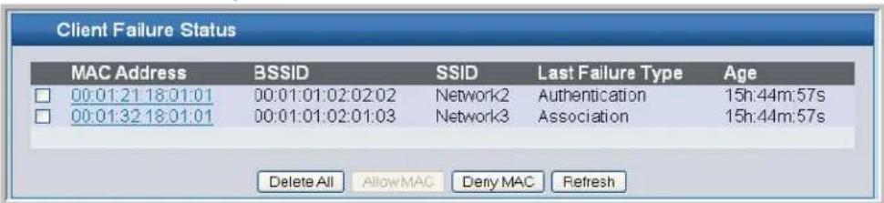
• To delete all clients from the list, click Delete All.
- To block a failed client from WLAN access, select the check box next to the MAC address of the client and click Deny MAC. The MAC address is added to the MAC Authentication Deny MAC List for all AP Profiles where the default action is Deny.
- To add the client to the MAC Authentication Allow MAC List for all profiles where the default action is Allow, select the client and click Allow MAC. You must re-apply the AP profiles in order for the changes to be applied to the APs.

Note: If the Deny MAC button is not available, it means all profiles use Allow as the default MAC Authentication action. Likewise, if the Allow MAC button is not available, no profiles have an Allow default action.

Note: If you use RADIUS for MAC authentication in one or more AP profiles, you must add the MAC Address to the RADIUS database.
Table 55 shows the fields on the summary page for failed client status.
Table 55: Failed Client Status
| Field Description | |
| MAC Address The Ethernet address of the client. | |
| BSSID The managed AP VAP Ethernet MAC address on which the client attempted to associate and/or authenticate. | |
| SSID The network SSID on which client attempted to associate and/or authenticate. | |
| Last Failure Type | Indicates the last type of failure that occurred, which can be Authentication or Association. |
| Age Time since failure occurred. | |
- Click Refresh to update the screen with the most current information.
Click the MAC address of the failed client to view additional information about a client.

Note: If a wrong password is entered on a client for WEP, this page may not list that authentication failed client. This issue actually arises from a known problem with the IEEE 802.11 specification. The specification says that if the AP is unable to decode the third frame (containing the encrypted challenge text), it should send an unsuccessful result. However, if the AP is unable to decode a WEP frame, it does not know whether that frame is actually the third frame, or even a Shared Key frame at all, and does not send a result. This issue only applies to WEP (which is not recommended due to security issues) that uses Shared Key authentication when the key is incorrect.
Software User Manual D-Link Unified Access System
02/15/2011
The client authentication failure status for an individual client shows information about the client that failed to authenticate or associate with an AP and list the number of authentication or association failures. A client with a high number of failed authentications might indicate a possible threat to the WLAN.
Table 56 shows the fields on the detail page for Client Authentication Failure Status.
Table 56: Client Authentication Failure Status
| Field Description | |
| MAC Address The Ethernet address of the client. | |
| BSSID The managed AP VAP Ethernet MAC address on which the client attempted to associate and/or authenticate. | |
| SSID The network SSID on which client attempted to associate and/or authenticate. | |
| Last Failure Type | Indicates the last type of failure that occurred, which can be Authentication or Association. |
| Authentication Failure Count Count of authentication failures for this client. | |
| Association Failure Count Count of association failures for this client. | |
| Age Time since failure occurred. | |
Monitoring and Managing Ad Hoc Clients
An ad hoc client is a wireless client that gains access to the WLAN through a wireless client that is associated with an access point. The ad hoc client does not communicate directly with the AP. Ad hoc networks are a particular concern because they consume RF bandwidth and can present a security risk.
Status entries for ad hoc clients are collected at a point in time and eventually age out. The age value for each entry shows how long ago the switch recorded the entry. You can configure the age out time for status entries on the Administration > Advanced Configuration > Global page. You can also manually delete status entries.
From the Monitoring > Client > Ad Hoc Clients page, you can view and manage wireless clients that are connected to the WLAN through an ad hoc network.
Figure 69: Ad Hoc Clients
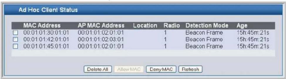
• To delete the ad hoc client entries from the list, click Delete All. The status list is cleared on the switch.

Note: Clearing the list does not disassociate any of the ad hob clients, and the clients might still be involved in the ad hoc network.
- If you want to block an ad hoc client from WLAN access, select the check box next to the MAC address of the client and click Deny MAC. The MAC address is added to the MAC Deny List in the AP Profile MAC Authentication settings.
- If you select the check box and click Allow MAC, the MAC address is added to the Allow MAC List in the AP Profile MAC Authentication settings.

Note: The MAC address is added to the local MAC authentication list for all profiles where the global default action is set to allow (for Allow MAC), or deny (for Deny MAC). If you use RADIUS for MAC authentication in one or more AP profiles, you must add the MAC to the RADIUS database.
- Click Refresh to update the screen with the most current information.
Each AP profile has one global MAC authentication list which is either a list to deny access to all MAC addresses on the list or to allow access to all MAC addresses on the list. To set the mode for the default AP Profile, click the Administration > Basic Setup > AAA/RADIUS tab. Set the MAC Authentication Default Action field to Allow or Deny all MAC Addresses in the list. To set the mode for a different AP profile go to the Global tab on the AP Profile to configure.
The switch does not remove MAC entries from this list even when a client successfully authenticates with an AP. The historical ad hoc data gives you more time to take action against clients that establish ad hoc networks on the WLAN.
Table 57: Ad Hoc Client Status
| Field Description | |
| MAC Address | The Ethernet address of the client. If the Detection Mode is Beacon then the client is represented as an AP in the RF Scan database and the Neighbor AP List. If the Detection Mode is Data Frame then the client information is in the Neighbor Client List. |
| AP MAC Address | The base Ethernet MAC Address of the managed AP which detected the client. |
| Location The configured descriptive location for the managed AP. | |
| Radio The radio interface and its configured mode that detected the ad hoc device. | |
| Detection Mode | The mechanism of detecting this Ad Hoc device. The possible values are Beacon Frame or Data Frame. |
| Age Time in seconds since last detection of the ad hoc network. | |
Section 9: Configuring Advanced Settings
This chapter contains the following sections to help you configure your D-Link Unified Access System network:
- "Creating, Configuring, and Managing AP Profiles"
- "Configuring Global Settings"
- "Enabling SNMP Traps"
- "Configuring QoS"
Creating, Configuring, and Managing AP Profiles
Access point configuration profiles are a useful feature for large wireless networks with APs that serve a variety of different users. You can create multiple AP profiles on the D-Link Unified Switch to customize APs based on location, function, or other criteria. Profiles are like templates and, once you create an AP profile, you can apply that profile to any AP that the Unified Switch manages.
For each AP profile, you can configure the following features:
• Global RADIUS settings
• MAC authentication list
- Radio settings
• Network settings
- QoS configuration
Figure 70 shows ten APs that are managed by a D-Link Unified Switch in a campus network. Each building has multiple APs, and the users in one building have different network requirements than the users in other buildings. The administrator of this WLAN has created two AP profiles on the switch in addition to the default profile.
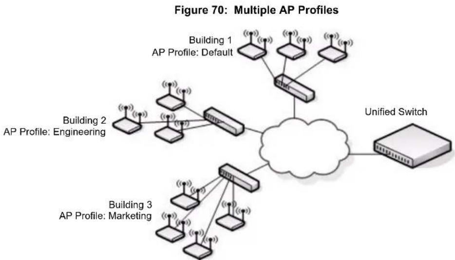
flowchart
graph TD
    subgraph AP_Profiles_Architecture
        A["Building 1: Default"] --> B["AP Profile: Default"]
        C["Building 2: Engineering"] --> D["AP Profile: Engineering"]
        E["Building 3: Marketing"] --> F["AP Profile: Marketing"]
    end
    B --> G["Unified Switch"]
    F --> G
    style G fill:#f9f,stroke:#333,stroke-width:2px
Building 1 contains the main lobby and several conference rooms. The WLAN users in this location are primarily non-employees and guests. The APs in Building 1 uses the default AP profile with no additional networks and no security.
Building 2 is the engineering building. The Building 2 APs use a profile called "Engineering." The Engineering profile has three different VAPs that each have a unique SSID: Hardware, Software and Test.
Building 3 is the Sales and Marketing building. The Building 3 AP uses a profile called "Marketing." The Marketing AP Profile has three VAPs. The SSIDs for the VAPs are: Sales, Marketing, and Program Management.
If the network administrator adds another AP to Building 2, she assigns the Engineering profile to the AP during the AP validation process.
Creating, Copying, and Deleting AP Profiles
From the Access Point Profile Summary page, you can create, copy, or delete AP profiles. You can create up to 16 AP Profiles on the D-Link Unified Switch. To create a new profile, enter the name of the profile in the Profile Name field, and then click Add.
Figure 71: Adding a Profile
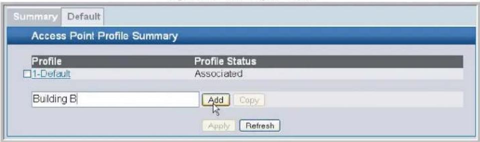
After you add the profile, the Global Configuration page for the profile appears, and a new tab with the name of the profile appears at the top of the page. Click the Radio, VAP, or QoS tabs to configure additional features for the profile.
Figure 72 shows the layout for AP Profile configuration.
Figure 72: Configuring an AP Profile
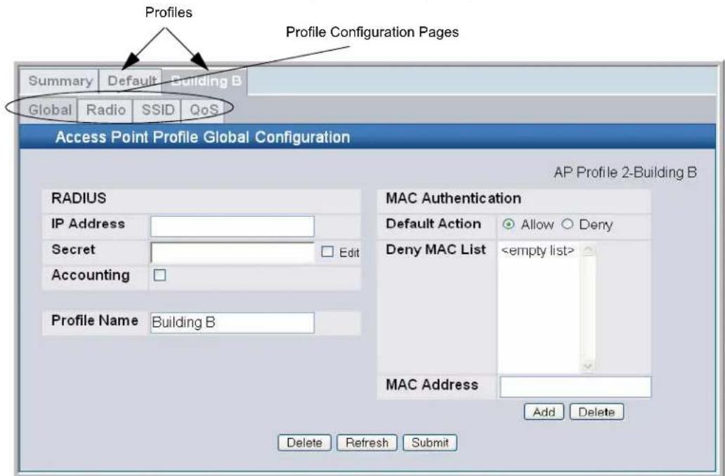
To copy an existing profile and all of its configurations to a new profile, select the profile with the configuration to copy, enter a name for the new profile, and click Copy.
To delete a profile, select the profile and click Delete.

Note: You cannot delete a profile if the switch is managing an access point that is currently using that profile.
Click Refresh to update the screen with the most current information.
To access an existing profile, click the tab with the name of the profile. When you add a new profile, it has the default AP settings, which are listed in Appendix A "D-Link Unified Access System Default Settings". When you copy a profile, it has the AP settings configured in the original profile.
To modify any settings within a profile, click the Global, Radio, Network or QoS settings for the profile you select and update the appropriate fields.
For more information about the fields on the Global page, see "Configuring AAA and RADIUS Settings" on page 79.
For more information about the fields on the Radio page, see "Configuring Wireless Radio Settings" on page 81.
For more information about the fields on the Network page, see "Configuring SSID Settings" on page 86.
For more information about the fields on the QoS page, see "Click Submit to update the switch with the values on the screen. If you want the switch to retain the new values across a power cycle you must perform a save." on page 159.
Applying an AP Profile
After you update an AP Profile on the Unified Switch, the changes are not applied to the access points that use that profile until you explicitly apply the profile on the Access Point Profile Summary page or reset the APs that use the profile.

Note: When you change the VLAN ID for a wireless network, the AP might temporarily lose its DHCP-assigned IP address when you apply the updated profile. If this occurs, the AP goes into Standalone mode. As soon as the AP regains its IP address from the DHCP server on your network, it resumes normal operation as a managed AP. You might also see this behavior when you enable or disable a VAP (SSID) and re-apply the AP profile.
To apply the profile changes to all access points that use a profile, select the profile and click Apply, as Figure 73 shows.
Figure 73: Applying the AP Profile

Selected Profile to Apply

Note: When you apply new AP Profile settings to an AP, the access point stops and restarts system processes. If this happens, wireless clients will temporarily lose connectivity. We recommend that you change access point settings when WLAN traffic is low.
The Profile Status field can have one of the following values:
• Associated—The profile is configured, and one or more APs managed by the switch are associated with this profile.
- Associated-Modified—The profile has been modified since it was applied to one or more associated APs; the profile must be re-applied for the changes to take effect.
- Apply Requested—After you select a profile and click Apply, the screen refreshes and shows that an apply has been requested.
- Apply In Progress—The profile is being applied to all APs that use this profile. During this process the APs reset, and all wireless clients are disassociated from the AP.
- Configured—The profile is configured, but no APs managed by the switch currently use this profile.

Note: You associate a profile with an AP in the Valid AP database.
Configuring Global Settings
The fields on the Administration > Advanced Configuration > Global > General tab are settings that apply to the D-Link Unified Switch.
Figure 74: Global Configuration
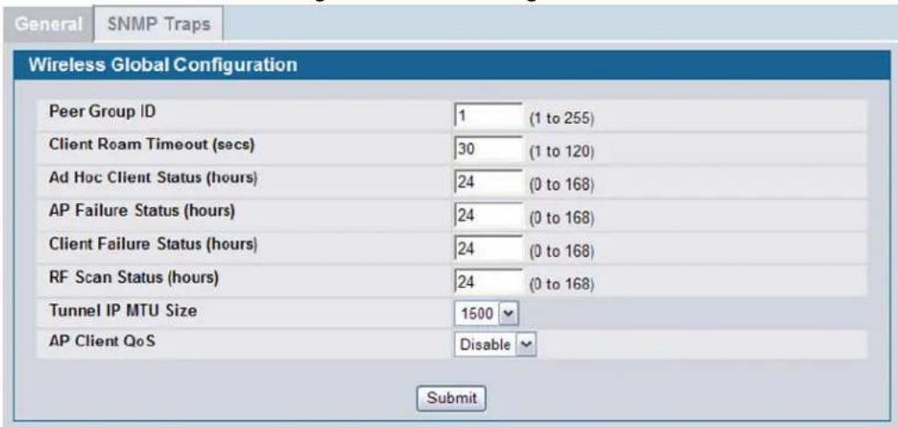
Table 58 describes the fields on the Wireless Global Configuration page.
Table 58: General Global Configurations
| Field Description | |
| Peer Group ID | In order to support larger networks, you can configure Unified Switches as peers, with up to 4 switches in a peer group. Peer Unified Switches share some information about APs and allow L3 roaming among them.Peer Unified Switches are grouped according to the Group ID. |
| Client Roam Timeout | This value determines how long to keep an entry in the Associated Client Status list after a client has disassociated. Each entry in the status list shows an age, and when the age reaches the value you configure in the timeout field, the entry is deleted. |
| Ad Hoc Client Status | This value determines how long to keep an entry in the Ad Hoc Client Status list. Each entry in the status list shows an age, and when the age reaches the value you configure in the timeout field, the entry is deleted. |
| AP Failure Status | This value determines how long to keep an entry in the AP Authentication Failure Status list. Each entry in the status list shows an age, and when the age reaches the value you configure in the timeout field, the entry is deleted. |
| Client Failure Status | This value determines how long to keep an entry in the Client Authentication Failure Status list. Each entry in the status list shows an age, and when the age reaches the value you configure in the timeout field, the entry is deleted. |
| RF Scan Status | This value determines how long to keep an entry in the RF Scan Status list. Each entry in the status list shows an age, and when the age reaches the value you configure in the timeout field, the entry is deleted. |
Table 58: General Global Configurations
| Field Description | |
| Tunnel IP MTU Size | Sets the maximum size of the IP packet handled by the network. The MTU is enforced only on tunneled VAPs. Select one of the following values:1500: Maps the tunneled IP frame size to 1518 bytes (untagged) and 1522 bytes (tagged). Use this setting if your network does not support jumbo frames. Using 1500 as the Tunnel IP MTU size forces the D-Link Unified Access System to limit its maximum message size to 1518/1522 bytes. This setting directs the wireless system to mitigate the problem of oversized frames by enabling the MTU discovery protocol and limiting the maximum segment size in TCP connection setup messages.1520: Maps the tunneled IP frame size to 1538 bytes (untagged) and 1542 bytes (tagged). Use this setting if your network supports jumbo frames and you have configured the physical ports between the switch and the APs to support 1538/1542 byte packets.IP Packets that use the L3 tunnel have an extra 20 bytes in the header for encapsulation. This means that wireless clients configured with a 1500 byte IP MTU size may exceed the maximum MTU size of the existing network infrastructure if it is set up to switch and route 1518 (1522-tagged) byte frames.Setting the Network MTU Size to 1500 or 1520 does not affect physical port MTU size. The physical ports on the switch and the rest of the network devices must be configured with the appropriate MTU size.Note: If the AP is not connected directly to the wireless switch and the Tunnel IP MTU Size is set to 1520, any Ethernet segments in the path between the AP and the wireless switch must support jumbo frames and be configured for jumbo frames. |
| AP Client QoS | Select this option to apply access control lists (ACLs) and differentiated service (DiffServ) policies to the AP. |
Click Submit to update the switch with the values on the screen. If you want the switch to retain the new values across a power cycle you must perform a save.
Enabling SNMP Traps
If you use Simple Network Management Protocol (SNMP) to manage the D-Link Unified Switch, you can configure the SNMP agent on the switch to send traps to the SNMP manager on your network from the Administration > Advanced Configuration > Global > SNMP Traps tab.
Figure 75: SNMP Trap Configuration
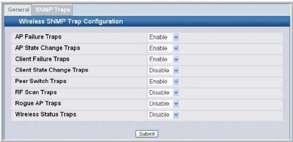
Software User Manual D-Link Unified Access System
02/15/2011
The AP does not send out any traps. The switch generates all SNMP traps based on its own events and events it learns about through updates from the APs it manages.
Table 59 describes the events that generate SNMP traps. All traps are disabled by default.
Table 59: SNMP Traps
| Field Description | |
| AP Failure Traps | If you enable this field, the SNMP agent sends a trap if an AP fails to associate or authenticate with the switch. |
| AP State Change Traps | If you enable this field, the SNMP agent sends a trap for one of the following reasons:Managed AP DiscoveredManaged AP FailedManaged AP Unknown Protocol DiscoveredManaged AP Load Balancing Utilization Exceeded |
| Client Failure Traps | If you enable this field, the SNMP agent sends a trap if a wireless client fails to associate or authenticate with an AP that is managed by the switch. |
| Client State Change Traps | If you enable this field, the SNMP agent sends a trap for one of the following reasons associated with the wireless client:Client Association DetectedClient Disassociation DetectedClient Roam Detected |
| Peer Switch Traps | If you enable this field, the SNMP agent sends a trap for one of the following reasons associated with a peer switch:Peer Unified Switch DiscoveredPeer Unified Switch FailedPeer Unified Switch Unknown Protocol Discovered |
| RF Scan Traps | If you enable this field, the SNMP agent sends a trap when the RF scan detects a new AP, wireless client, or ad-hoc client. |
| Rogue AP Traps | If you enable this field, the SNMP agent sends a trap when the switch discovers a rogue AP. |
| Wireless Status Traps | If you enable this field, the SNMP agent sends a trap if the operational status of the D-Link Unified Switch changes or of any of the following databases or lists has reached the maximum number of entries:Managed AP databaseAP Neighbor ListClient Neighbor ListAP Authentication Failure ListRF Scan AP ListClient Association DatabaseClient Authentication Failure List |
| Client Authentication Trap | If you enable this field, the SNMP agent sends a trap when a wireless client authenticates successfully to the network through a captive portal. |
Click Submit to update the switch with the values on the screen. If you want the switch to retain the new values across a power cycle you must perform a save.
CONFIGURING QoS
Quality of Service (QoS) provides you with the ability to specify parameters on multiple queues for increased throughput and better performance of differentiated wireless traffic like Voice-over-IP (VoIP), other types of audio, video, and streaming media as well as traditional IP data over the D-Link Unified Access System.
For detailed information about QoS and how it is used in the D-Link Unified Access System, see Appendix D "Understanding Quality of Service".
Figure 76: QoS Configuration
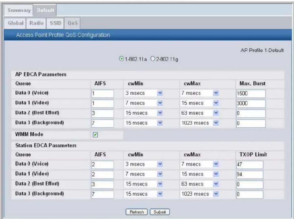
Configuring QoS on the D-Link Unified Access System consists of setting parameters on existing queues for different types of wireless traffic, and effectively specifying minimum and maximum wait times (through Contention Windows) for transmission. The settings described here apply to data transmission behavior on the access point only, not to that of the client stations.
AP Enhanced Distributed Channel Access (EDCA) Parameters affect traffic flowing from the access point to the client station. Station Enhanced Distributed Channel Access (EDCA) Parameters affect traffic flowing from the client station to the access point.

Note: QoS is configured per radio interface.
Table 60 describes the QoS settings you can configure.
Table 60: QoS Settings
| Field Description | |
| Queue Queues are defined for different types of data transmitted from AP-to-station:Data 0 (Voice)High priority queue, minimum delay. Time-sensitive data such as VoIP and streaming media are automatically sent to this queue.Data 1(Video)High priority queue, minimum delay. Time-sensitive video data is automatically sent to this queue.Data 2 (best effort)Medium priority queue, medium throughput and delay. Most traditional IP data is sent to this queue.Data 3 (Background)Lowest priority queue, high throughput. Bulk data that requires maximum throughput and is not time-sensitive is sent to this queue (FTP data, for example). | |
| AIFS (Inter-Frame Space) | The Arbitration Inter-Frame Spacing (AIFS) specifies a wait time (in milliseconds) for data frames.Valid values for AIFS are 1 through 255. |
| cwMin (Minimum Contention Window) | This parameter is input to the algorithm that determines the initial random backoff wait time ("window") for retry of a transmission.The value specified here in the Minimum Contention Window is the upper limit (in milliseconds) of a range from which the initial random backoff wait time is determined.The first random number generated will be a number between 0 and the number specified here.If the first random backoff wait time expires before the data frame is sent, a retry counter is incremented and the random backoff value (window) is doubled. Doubling will continue until the size of the random backoff value reaches the number defined in the Maximum Contention Window.Valid values for the "cwmin" are 1, 3, 7, 15, 31, 63, 127, 255, 511, or 1023. The value for "cwmin" must be lower than the value for "cwmax". |
| cwMax (Maximum Contention Window) | The value specified here in the Maximum Contention Window is the upper limit (in milliseconds) for the doubling of the random backoff value. This doubling continues until either the data frame is sent or the Maximum Contention Window size is reached.Once the Maximum Contention Window size is reached, retries will continue until a maximum number of retries allowed is reached.Valid values for the "cwmax" are 1, 3, 7, 15, 31, 63, 127, 255, 511, or 1023. The value for "cwmax" must be higher than the value for "cwmin". |
| Max. Burst Length | AP EDCA Parameter Only (The Max. Burst Length applies only to traffic flowing from the access point to the client station.)This value specifies (in milliseconds) the Maximum Burst Length allowed for packet bursts on the wireless network. A packet burst is a collection of multiple frames transmitted without header information. The decreased overhead results in higher throughput and better performance.Valid values for maximum burst length are 0 through 999. |
| WMM Mode | Wi-Fi MultiMedia (WMM) is enabled by default. With WMM enabled, QoS prioritization and coordination of wireless medium access is on. With WMM enabled, QoS settings on the D-Link Unified Access System controldownstreamtraffic flowing from the access point to client station (AP EDCA parameters) and theupstreamtraffic flowing from the station to the access point (station EDCA parameters).Disabling WMM deactivates QoS control of station EDCA parameters onupstreamtraffic flowing from the station to the access pointWith WMM disabled, you can still set some parameters on the downstream traffic flowing from the access point to the client station (AP EDCA parameters).To disable WMM extensions, clickDisabled.To enable WMM extensions, clickEnabled. |
| Queue Queues are defined for different types of data transmitted from station-to-AP:Data 0 (Voice)Highest priority queue, minimum delay. Time-sensitive data such as VoIP and streaming media are automatically sent to this queue.Data 1(Video)Highest priority queue, minimum delay. Time-sensitive video data is automatically sent to this queue.Data 2 (best effort)Medium priority queue, medium throughput and delay. Most traditional IP data is sent to this queue.Data 3 (Background)Lowest priority queue, high throughput. Bulk data that requires maximum throughput and is not time-sensitive is sent to this queue (FTP data, for example). | |
| AIFS (Inter-Frame Space) | The Arbitration Inter-Frame Spacing (AIFS) specifies a wait time (in milliseconds) for data frames.Valid values for AIFS are 1 through 255. |
| cwMin (Minimum Contention Window) | This parameter is input to the algorithm that determines the initial random backoff wait time ("window") for retry of a transmission.The value specified in the Minimum Contention Windowis the upper limit (in milliseconds) of a range from which the initial random backoff wait time is determined.The first random number generated will be a number between 0 and the number specified here.If the first random backoff wait time expires before the data frame is sent, a retry counter is incremented and the random backoff value (window) is doubled. Doubling will continue until the size of the random backoff value reaches the number defined in the Maximum Contention Window.Valid values forcwMinare 1, 3, 7, 15, 31, 63, 127, 255, 511, or 1023. The value for cwMin can be equal to or lower than the value for cwMax. |
| cwMax (Maximum Contention Window) | The value specified in the Maximum Contention Windowis the upper limit (in milliseconds) for the doubling of the random backoff value. This doubling continues until either the data frame is sent or the Maximum Contention Window size is reached.Once the Maximum Contention Window size is reached, retries will continue until a maximum number of retries allowed is reached.Valid values forcwMaxare 1, 3, 7, 15, 31, 63, 127, 255, 511, or 1023. The value for cwMax can be equal to or higher than the value for cwMin. |
Software User Manual D-Link Unified Access System
02/15/2011
Table 60: QoS Settings (Cont.)
| Field Description | |
| TXOP Limit | Station EDCA Parameter Only (The TXOP Limit applies only to traffic flowing from the client station to the access point.)The Transmission Opportunity (TXOP) is an interval of time when a WME client station has the right to initiate transmissions onto the wireless medium (WM).This value specifies (in milliseconds) the Transmission Opportunity (TXOP) for client stations; that is, the interval of time when a WMM client station has the right to initiate transmissions on the wireless network.The TXOP Limit range is 0 to 65535. The value is in units of 32-microsecond periods. |
Use the buttons at the bottom of the page to perform the following tasks:
- Click Refresh to update the screen with the most current information.
- Click Submit to update the switch with the values on the screen. If you want the switch to retain the new values across a power cycle you must perform a save.
Section 10: Configuring the Captive Portal
The Captive Portal (CP) feature allows you to block wired and wireless clients from accessing the network until user verification has been established.
This chapter contains the following sections to help you configure and monitor the CP feature on the Unified Switch.
- "Configuring Global Captive Portal Settings"
- "Configuring the Captive Portal"
• "Monitoring and Configuring Captive Portal Users"
• "Associating Interfaces with the Captive Portal"
• "Viewing the Captive Portal Global Status"
• "Viewing the Client Summary" - "SNMP Trap Configuration"
For information about the commands you use to manage and maintain the APs by using the CLI, see the D-Link CLI Command Reference.

Note: The captive portal configuration pages are available from the Security folder under both the LAN and WLAN tabs.
Figure 77: Navigating to the Captive Portal Feature
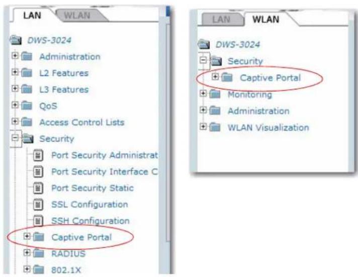
Configuring Global Captive Portal Settings
Use the CP Global Configuration page to control the administrative state of the CP feature and configure global settings that affect all captive portals configured on the switch. To configure the global CP settings, click Security > Captive Portal > Global Configuration.
Figure 78: Global Captive Portal Configuration
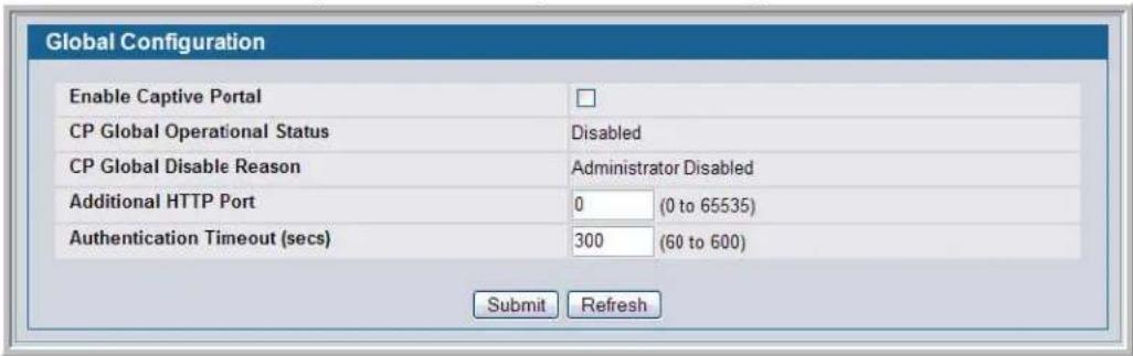
Table 61 describes the global CP fields you can view or configure.
Table 61: Global Captive Portal Configuration
| Field Description | |
| Enable Captive Portal | Select the check box to enable the CP feature on the switch. Clear the check box to disable the captive portal feature. |
| CP Global Operational Status Shows whether the CP feature is enabled. | |
| CP Global Disable Reason | If CP is disabled, this field displays the reason, which can be one of the following:NoneAdministratively DisabledNo IPv4 AddressRouting Enabled, But no IPv4 routing interface |
| Additional HTTP Port | HTTP traffic uses port 80, but you can configure an additional CP authentication server port for HTTP web connection. Enter a port number between 0-65535 (excluding port 80, 443, and the configured switch management port). The HTTP port default is 0 which denotes no additional port. |
| Authentication Timeout | To access the network through a portal, the client must first enter authentication information on an authentication Web page. Enter the number of seconds to keep the authentication session open with the client. When the timeout expires, the switch disconnects any active TCP or SSL connection with the client. The range is 60-600 seconds. The default is 300 seconds. |
Use the buttons at the bottom of the page to perform the following tasks:
- Click Submit to update the switch with the values on the screen. If you want the switch to retain the new values across a power cycle you must perform a save.
- Click Refresh to update the screen with the most current information.
Configuring the Captive Portal
Use the CP Summary page to create or delete captive portal configurations. The switch supports 10 CP configurations. CP configuration 1 is created by default and can not be deleted. Each CP configuration can contain up to 5 locale specific web configurations. Therefore a total maximum of 50 custom web page configurations can be created. Each captive portal configuration can have unique guest or group access modes and a customized acceptance use policy that displays when the client connects.
To view summary information about existing captive portals, or to add or delete a captive portal, click Security > Captive Portal > CP Configuration.
Figure 79: Captive Portal Summary
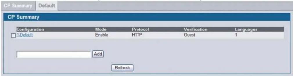
To create a CP configuration, enter the configuration name in the text box and click Add. After you add the configuration, the CP Configuration page for that configuration displays, and a new tab with the name of that configuration appears.
To delete an existing CP, select the check box for the CP to remove, and then click Delete.
To configure the settings for an existing CP, click the name in the Configuration column or click the appropriate tab.
Table 62 describes the fields on the CP Summary page.
Table 62: Captive Portal Summary
| Field Description | |
| Configuration Shows the captive portal ID and name. To access the configuration page for an existing CP, click the configuration name. | |
| Mode Shows whether the CP is enabled. | |
| Protocol Indicates whether the portal uses HTTP or HTTPS. | |
| Verification Specifies which type of user verification to perform: ·G u e s t : The user does not need to be authenticated by database. ·Local: The switch uses a local database to authenticate users. ·RADIUS: The switch uses a database on a remote RADIUS server to authenticate users. To configure authorized users on the local or remote RADIUS database, see “Monitoring and Configuring Captive Portal Users” on page 177. |
Click Refresh to update the screen with the most current information.
Changing the Captive Portal Settings
By default, the D-Link Unified Switch has one captive portal. You can change the settings for that captive portal, and you can also create and configure up to nine additional portals. After you create a captive portal from the CP Summary page, you can change its settings.
Figure 80: Captive Portal Configuration
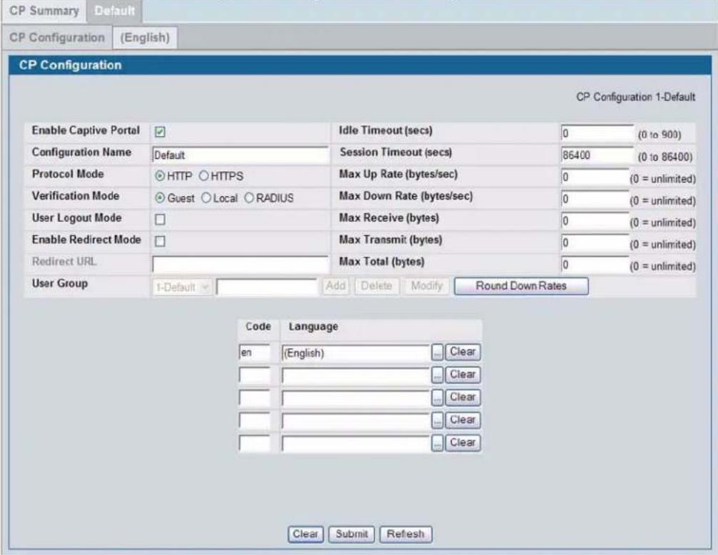
Table 63 describes the fields on the CP Configuration page.
Table 63: CP Configuration
| Field Description |
| Enable Captive Portal Select the check box to enable the CP. Clear the check box to disable it. The default is Enable. |
| Configuration Name This field allows you to change the name of the portal added from the CP Summary page. The range is 0-32 characters. The default name is Default. |
Table 63: CP Configuration (Cont.)
| Field | Description |
| Protocol Mode Choose whether to use HTTP or HTTPS as the protocol for the portal to use during the verification process.·HTTP: Does not use encryption during verification·HTTPS: Uses the Secure Sockets Layer (SSL), which requires a certificate to provide encryption. The certificate is presented to the user at connection time.The default is HTTP. | |
| Verification Mode Select the mode for the CP to use to verify clients:·G u e s t : The user does not need to be authenticated by database.·Local: The switch uses a local database to authenticate users.·RADIUS: The switch uses a database on a remote RADIUS server to authenticate users.The default is Guest. | |
| User Logout Mode Select the check box to specify that the user logout will be used.Selecting the check box enables client side de-authentication requests for this configuration.In order for the user logout to function properly, the client browser must be configured such that javascript is enabled and popup windows are allowed. For more information, see “Customizing the Captive Portal Web Page” on page 170. | |
| Enable Redirect Mode Select the check box to specify that the CP should redirect thenewly authenticated client to the configured URL. If the check box is clear, the user sees the locale-specific welcome page after a successful verification. | |
| Redirect URL Specify the URL to which the newly authenticated client is redirected if the URL Redirect Mode is enabled. The range is 0-256 characters. | |
| User Group If the Verification Mode is Local or RADIUS, assign an existingUser Group to the captive portal or create a new group. All users who belong to the group are permitted to access the network through this portal. The User Group list is the same for all CP configurations on the switch.The User Group field also allows you to add, delete, or rename user groups for all captive portals.To assign an existing user group to the CP, select it from the menu.To create a new user group, enter the group name in the blank field and click Add. The name can be 0-32 characters. The default name is Default.To delete a user group, select it from the menu and click Delete.Note: The User Group fields are unavailable if the Verification Mode is Guest.To change the name of an existing user group, select the name to change from the menu, enter the new name in the blank field, and click Modify. | |
| Idle Timeout (secs) Enter the number of seconds a user can remain idle before automatically being logged out. If the value is set to 0 then the timeout is not enforced. The range is 0 to 900. The default value is 0.Note: Idle timeout is not supported for wired clients. | |
| Session Timeout (secs) | Enter the number of seconds to wait before terminating a session. A user is logged out once the session timeout is reached. If the value is set to 0 then the timeout is not enforced. The range is 0 to 86400 seconds. The default value is 86400 seconds. |
| Max Up Rate (bytes/sec) | Enter the speed (bps) the client can transmit traffic when using the Captive Portal instance. A value of zero equals unlimited. |
| Max Down Rate (bytes/sec) | Enter the speed (bps) the client can receive traffic when using the Captive Portal instance. A value of zero equals unlimited. |
| Max Receive (bytes) | Enter the number of bytes a client is allowed to receive when using the Captive Portal instance. A value of zero equals unlimited. |
| Max Transmit (bytes) Enter the number of bytes a client is allowed to transmit when using the Captive Portal instance. A value of zero equals unlimited. | |
| Max Total (bytes) Enter the number of bytes a client is allowed to transfer when using the Captive Portal instance. A value of zero equals unlimited. | |
| Code Used to identify the user's language of choice for customized content. Enter the IANA Language Subtag code for the language. All codes are listed in the IANA Language Subtag Registry. If the language is currently supported by the switch, the code is filled in automatically when you select the language. The default is en. | |
| Language To add a captive portal configuration in a language that is supported by the switch, click the ... button to display and select the language to use for the captive portal. The range is 1-32 Unicode characters. You must provide a label. The default is English.To remove a captive portal configuration in a language, click Clear. | |
Use the buttons on the page to perform the following tasks:
- Because the Max Up Rate and the Max Down Rate have to be set to n*1000 bytes/sec (n = 0, 1, 2...), click the Round Down Rates button to:
- Round down the values to the nearest multiple of 1000 bytes/sec if the value entered is greater than 1000 bytes/second. For example, if the rate is 1200 bps, click the Round Down Rates button to round down the value to 1000 bps.
- Round up to 1000 bytes/sec if the value entered is less than 1000 bytes/second. For example, if the rate is 400 bps, click the Round Down Rates button to round up the value to 1000 bps.
- Click Clear to reset the page to the default values.
- Click Submit to update the switch with the values on the screen. If you want the switch to retain the new values across a power cycle you must perform a save.
- Click Refresh to update the screen with the most current information.
Customizing the Captive Portal Web Page
When a client connects to the switch, either through a wired connection or through an access point, the user is presented with the captive portal Web page. The CP Web Page Customization page allows you to customize the appearance of that page with specific text and images.
You can create up to five locale-specific web pages for each captive portal as long as the pages all use the same verification type; either guest or authorized user web pages. This allows you to create pages in a variety of languages to accommodate a diverse group of users.
To customize the page that wired and wireless clients see when they access the captive portal, click the tab that corresponds to the language of the page to customize.
Custom Background
The administrator can optionally specify the background image to be used for the client authentication screen on the user's browser window.
Custom Authentication Logout Request
The administrator can optionally configure and enable user logout. This feature allows the authenticated clients to deauthenticate from the network. In response to the request, the authenticated user is removed from the connection status tables and, for wireless clients, they are disassociated. If the client logout request feature is not enabled, or the user does not specifically request logout, the user connection status will remain authenticated until such time as Captive Portal deauthenticates (for example, session timeout, idle time, etc.) In order for the user logout to function properly, the client browser must be configured such that javascript is enabled and popup windows are allowed.
From the menu, select the CP web page to customize. Options are:
• Global Parameters described in Table 64 on page 172.
• Authentication Page described in Table 65 on page 173.
• Welcome Page described in Table 66 on page 175.
- Logout Page described in Table 67 on page 176.
- Logout Success Page described in Table 68 on page 176.
The web page option the administrator selects determines which fields are displayed on the CP Web Page Customization page.
Figure 81: CP Web Page Customization - Global Parameters
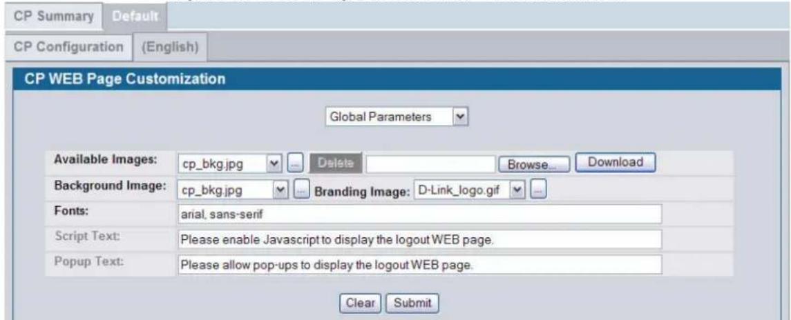
The following table describes the fields on the CP Web Page Customization - Global Parameters page.
Table 64: CP Web Page Customization - Global Parameters
| Field Description | |
| Available Images The menu shows the images that are available to use for the pagebranding and the account image. To add images, clickBrowseand select an image on your local system (or accessible from yourlocal system). ClickDownloadto download the image to theswitch.The image should be 5 KB max, 200 x 200 pixels, GIF or JPGformat.To delete an image from the list, select the file name from themenu and clickDelete. You can only delete images that youdownload. | |
| Background Image The administrator can optionally specify the background image tobe used for the client authentication screen on the user's browserwindow. The range is 0-32 characters. The default is cp_bkg.jpg. | |
| Branding Image Select the name of the image file to display on the top left cornerof the page. This image is used for branding purposes, such as thecompany logo. The image should be 5KB maximum, 200x200pixels, GIF or JPG format. The range is 0-32 characters. Thedefault is D-Link_logo.gif. | |
| Fonts Enter the name of the font to use for all text on the CP page. Aprioritized, comma separated, list of fonts is used by the clientbrowser. Font specifications are necessary for proper localdisplay. The range is 1-512 characters. The default is "MS UIGothic", Arial, sans-serif" for Japanese, all others "Arial, sans-serif". | |
| Script Text Optional text used to indicate to the client that java script shouldbe enabled. The range is 0-128 Unicode characters. The defaultis To take advantage of the full functionality of the authorizationprocess, please enable java script. | |
| Popup Text Optional text used to remind the user to allow pop-ups for this website so that they can de-authenticate when finished using thenetwork. The range is 0-128 Unicode characters. The default is Totake advantage of the full functionality of the authorizationprocess, please allow pop-ups from our web site. |
Use the buttons at the bottom of the page to perform the following tasks:
- Click Clear to reset the page to the default values.
- Click Submit to update the switch with the values on the screen. If you want the switch to retain the new values across a power power cycle you must perform a save.
Figure 82: CP Web Page Customization - Authentication Page
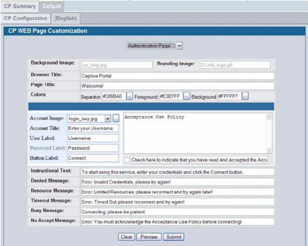
The following table describes the additional fields on the CP Web Page Customization - Authentication page.
Table 65: CP Web Page Customization - Authentication Page
| Field Description | |
| Browser Title | Enter the text to display on the client's Web browser title bar or tab. The range is 1-128 Unicode characters. The default is Captive Portal. |
| Page Title | Enter the text to use as the page title. This is the text that identifies the page and is used to greet the user. The range is 1-128 Unicode characters and must provide a greeting. The default is Welcome! |
| Colors | Select the colors to use for the CP page. Click the ... button, and then select the color to use. The sample account information is updated with the colors you choose.Separator - Separator bar color of the login page using a well known name or RGB value. The range is 1-32 characters. The default is #BFBFBF.Foreground - Foreground color of the login page using a well known color name or RGB value. The range is 1-32 characters. The default is 999999.Background - Background color of login page using a well known color name or RGB value. The range is 1-32 characters. The default is #BFBFBF. |
| Field | Description |
| Account Image | Select the optional account image that is stretched across the account column. To download a new image to the switch, use the Available Image field. The image name is 0-32 characters. The default is login_key.jpg. |
| Account Title | Enter the summary text to display that instructs users to authenticate. The range is 0-32 Unicode characters. The default is Enter your username. |
| User Label | Enter the text to display next to the field where the user enters the username. If the Guest account and label is not empty, then the label is displayed with user prompting. The range is 0-32 Unicode characters. The default is Username. |
| Password Label | Enter the text to display next to the field where the user enters the password. The label is not applicable for Guest accounts. The range is 0-64 Unicode characters. The default is Password. |
| Button Label | Enter the text to display on the button the user clicks to connect to the network. The range is 2-32 Unicode characters. The default is Connect. |
| AUP Text used to specify the appropriate Acceptance Use Policy. A default AUP is not preloaded. The range is 0-8192 Unicode characters. The default is Acceptance Use Policy. | |
| Accept Label | Select the option to display the Accept label text. The range is 0-128 Unicode characters. The default is Check here to indicate that you have read and accepted the Acceptance Use Policy. |
| Instructional Text | Enter the detailed text to display that instructs users to authenticate. This text appears under the button. The range is 0-256 Unicode characters. The default is To start using this service, enter your credentials and click the Connect button. |
| Denied Message | Enter the text to display when the user does not provide valid authentication information. This message also appears when the user is not a member of the user group assigned through the CP Configuration page. This message displays after the user clicks the button to connect to the network. The range is 1-128 Unicode characters. The default is Error: Invalid Credentials, please try again! |
| Resource Message | Enter the text to display when the system has rejected authentication due to system resource limitations. This message displays after the user clicks the button to connect to the network. The range is 1-128 Unicode characters. The default is Error: Limited resources, please reconnect and try again later! |
| Timeout Message | Enter the text to display when the system has rejected authentication because the authentication transaction took too long. This could be due to user input time, or a timeout due to the overall transaction. The range is 1-128 Unicode characters. The default is “Error: Timed Out, please reconnect and try again!” |
| Busy Message | Enter the text to display when the Captive Portal is processing the authentication request. This message displays after the user clicks the button to connect to the network. The range is 1-128 Unicode characters. The default is Connecting, please be patient. |
| No Accept Message | Enter the text to display when the user did not acknowledge the acceptance use policy. This message displays after the user clicks the button to connect to the network. The range is 1-128 Unicode characters. The default is Error: You must acknowledge the Acceptance User Policy before connecting! |
Figure 83: CP Web Page Customization - Welcome Page
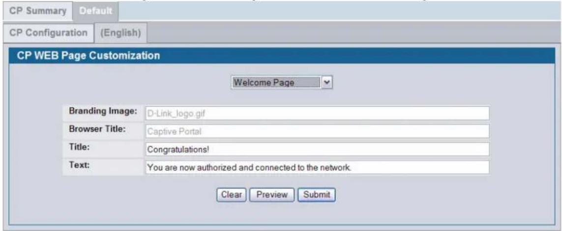
The following table describes the additional fields on the CP Web Page Customization - Welcome page.
Table 66: CP Web Page Customization - Welcome Page
| Field Description | |
| Title | Enter the title to display to greet the user after he or she successfully connects to the network. The range is 1-128 characters. The default is Congratulations! |
| Text | Enter the optional text to display to further identify the network to be accessed by the CP user. This message displays under the Welcome Title. The range is 0-256 Unicode characters. The default is You are now authorized and connected to the network. |
Figure 84: CP Web Page Customization - Logout Page
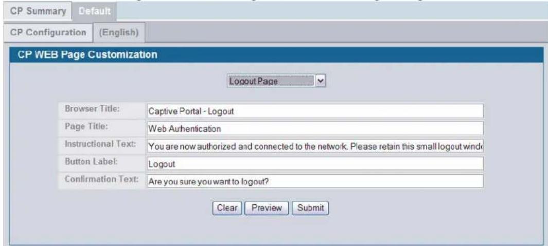
The following table describes the additional fields on the CP Web Page Customization - Logout page.
Table 67: CP Web Page Customization - Logout Page
| Field Description | |
| Browser Title | Title text displayed in client's logout browser title bar. The range is 1-128 Unicode characters. The default is Captive Portal – Logout. |
| Page Title | The primary title text. The range is 1-128 Unicode characters. You must provide a greeting. The default is Web Authentication. |
| Instructional Text | Text used to describe what the client logout popup window is used for. The range is 1-126 Unicode characters. The default is You are now authorized and connected to the network. Please retain this small logout window in order to de-authenticate. Press the Logout button when done. |
| Button Label | Enter the text to display on the button the user clicks to logout. The range is 2-32 Unicode characters. The default is Logout. |
| Confirmation Text | Enter the detailed text to confirm that the user wants to de-authenticate. This text appears under the button. The range is 1-128 Unicode characters. The default is Are you sure you want to logout? |
Figure 85: CP Web Page Customization - Logout Success Page
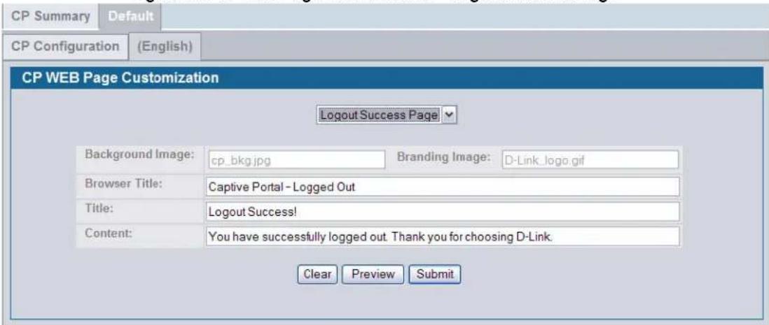
The following table describes the additional fields on the CP Web Page Customization - Logout Success page.
Table 68: CP Web Page Customization - Logout Success Page
| Field Description | |
| Background Image | Optional Background Image is configurable from the Global Parameters option of the CP Web Page Customization page. |
| Branding Image | Optional Branding Image is configurable from the Global Parameters option of the CP Web Page Customization page. |
| Browser Title | Title text displayed in client's logout browser title bar. The range is 1-128 Unicode characters. The default is Captive Portal – Logged Out. |
| Title | Enter the title to display to greet the user after he or she successfully logs out of the network. The range is 1-128 Unicode characters. You must provide a greeting. The default is Logout Success! |
Software User Manual D-Link Unified Access System
02/15/2011
Table 68: CP Web Page Customization - Logout Success Page
| Field Description | |
| Content | Enter the optional text to display to indicate successful de-authentication. This message displays under the logout success title. The range is 1-256 Unicode characters. The default is You have successfully logged out. Thank you for choosing D-Link. |
- Click Clear to reset the page to the default values.
- Click Preview to preview the customized page.
- Click Refresh to update the screen with the most current information.
- Click Submit to update the switch with the values on the screen. If you want the switch to retain the new values across a power cycle you must perform a save.
Monitoring and Configuring Captive Portal Users
You can configure a portal to accommodate guest users and authorized users. Guest users do not have assigned user names and passwords. Authorized users provide a valid user name and password that must first be validated against a local database or RADIUS server. Authorized users can gain network access once the D-Link Unified Switch confirms the user's credentials.
The Local User Summary page allows you to add authorized users to the local database, which can contain up to 128 user entries. You can also delete users from the local database from the Local User Summary page.
To view and configure CP users in the local database, click Security > Captive Portal > Local User.
Any users that are already configured are listed on the Local User Summary page.
Figure 86: Captive Portal Local User Summary
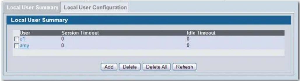
Table 69 describes the fields on the Local User Summary page.
Table 69: Local User Summary
| Field Description | |
| User Identifies the name of the user. | |
| Session Timeout | Shows the number of seconds a user is permitted to remain connected to the network. Once the Session Timeout value is reached, the user is logged out automatically. A value of 0 means that the user does not have a Session Timeout limit. |
Table 69: Local User Summary
| Field Description | |
| Idle Timeout | Shows the number of seconds the user can remain idle before the switch automatically logs the user out. A value of 0 means that the user will not be logged out automatically.Note: Idle timeout is not supported for wired clients. |
Use the buttons at the bottom of the page to perform the following tasks:
• To access the configuration page for a specific user listed on the page, click the user name.
• To add a new user and configure the Local User settings, click Add.
- To delete a user from the local database, select the check box next to the user to remove and click Delete. Select multiple check boxes to delete more than one user at a time.
- Click Delete All to remove all configured users from the local database.
- Click Refresh to update the screen with the most current information.
Configuring Users in the Local Database
From the Local User Configuration page, you can configure additional settings for an existing CP user in the local database.
Figure 87: Local User Configuration
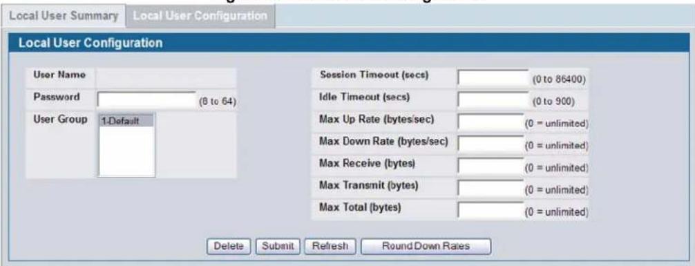
Table 70 describes the fields you use to configure CP users in the local database.
Table 70: Local User Configuration
| Field Description | |
| User Name Enter the name of the user. The range is 1-32 characters. | |
| Password | Enter an authentication password for the user. The password length can be from 8 to 64 characters. |
| User Group | Assign the user to at least one User Group. To assign a user to more than one group, press the Ctrl key and click each group. The range is 1-32 characters. The default is Default.New users are assigned to the 1-Default user group by default. |
| Group ID Unique group identifier. The range is an unsigned integer. The default is 1. | |
Table 70: Local User Configuration
| Field | Description |
| Session Timeout (secs) | Enter the number of seconds a user is permitted to remain connected to the network. Once the Session Timeout value is reached, the user is logged out automatically. A value of 0 means using the default value configured for the captive portal. The range is an integer in seconds, range 0 to 86400. The default is 0. |
| Idle Timeout (secs) | Enter the number of seconds the user can remain idle before the switch automatically logs the user out. A value of 0 means using the default value configured for the captive portal. The range is an integer 0 to 900 in seconds. The default value is 0.Note: Idle timeout is not supported for wired clients. |
| Max Up Rate (bytes/sec) | Enter the speed (bps) the client can transmit traffic when using the Captive Portal instance. |
| Max Down Rate (bytes/sec) | Enter the speed (bps) the client can receive traffic when using the Captive Portal instance. |
| Max Receive (bytes) | Enter the number of bytes a client is allowed to receive when using the Captive Portal instance. |
| Max Transmit (bytes) | Enter the number of bytes a client is allowed to transmit when using the Captive Portal instance. |
| Max Total (bytes) | Enter the number of bytes a client is allowed to transfer when using the Captive Portal instance. |
Use the buttons at the bottom of the page to perform the following tasks:
- Click Delete to delete the local user configuration.
- Click Submit to update the switch with the values on the screen. If you want the switch to retain the new values across a power cycle you must perform a save.
- Click Refresh to update the screen with the most current information.
- Because the Max Up Rate and the Max Down Rate have to be set to n*1000 bytes/sec (n = 0, 1, 2...), click the Round Down Rates button to:
- Round down the values to the nearest multiple of 1000 bytes/sec if the value entered is greater than 1000 bytes/second. For example, if the rate is 1200 bps, click the Round Down Rates button to round down the value to 1000 bps.
- Round up to 1000 bytes/sec if the value entered is less than 1000 bytes/second. For example, if the rate is 400 bps, click the Round Down Rates button to round up the value to 1000 bps.
Configuring Users in a Remote RADIUS Server
You can use a remote RADIUS server client authorization. You must add all users to the RADIUS server. The local database in the D-Link Unified Switch does not share any information with the remote RADIUS database.
Table 71 indicates the RADIUS attributes you use to configure authorized captive portal clients. The table indicates both RADIUS attributes and vendor-specific attributes (VSA). VSAs are denoted in the Attribute column and are comma delimited (vendor id, attribute id).
Table 71: Captive Portal User RADIUS Attributes
| Attribute | Number | Description | Range | Usage | Default |
| User-Name | 1 | User name to be authorized | 1-32 characters | Required None | |
Table 71: Captive Portal User RADIUS Attributes
| Attribute | Number | Description | Range | Usage | Default |
| User-Password 2 | User password | 8-64 | characters | Required None | |
| DLink-Captive-Portal-Groups | 6132, 127 | A comma-delimited list of group names that correspond to the configured CP instance configurations. | String Optional None. The | default group is used if not defined here. | |
| Session-Timeout 27 | Logout once | session timeout is reached (seconds). If the attribute is 0 or not present then use the value configured for the captive portal. | Integer (seconds) | Optional 0 | |
| Idle-Timeout 28 | Logout once | idle timeout is reached (seconds). If the attribute is 0 or not present then use the value configured for the captive portal. | Integer (seconds) | Optional 0 | |
Associating Interfaces with the Captive Portal
From the Interface Association page, you can associate a configured captive portal with a specific physical interface or wireless network (SSID). The CP feature only runs on the wired or wireless interfaces that you specify. A CP can have multiple interfaces associated with it, but an interface can be associated to only one CP at a time.
To associate interfaces with CPs, click Security > Captive Portal > Interface Association.

Note: When associating a physical interface with a captive portal configuration, note the following restrictions:
- Captive portal and STP should not be enabled on the same physical interface.
- Captive portal and 802.1X cannot be enabled on the same physical interface.
- Port security and captive portal cannot be enabled on the same physical interface.
- If a physical interface is made a LAG member, the captive portal becomes disabled on the interface.
Figure 88: Global Captive Portal Configuration
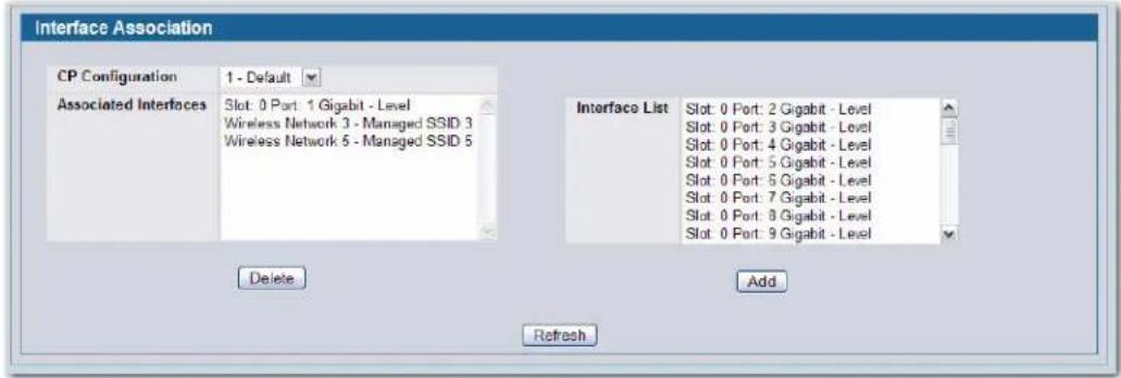
Table 72 describes the fields on the Interface Association page.
Table 72: Global Captive Portal Configuration
| Field Description | |
| CP Configuration Lists the captive portals configured on the switch by number and name. | |
| Associated Interfaces | Lists the interfaces that are currently associated with the selected captive portal. Wireless interfaces are identified by the wireless network number and SSID. Physical (wired) interfaces are identified by the Port Description that includes slot number, port number, and interface type. |
| Interface List | Lists the interfaces available on the switch that are not currently associated with a CP. Wireless interfaces are identified by the wireless network number and SSID. Physical (wired) interfaces are identified by the Port Description that includes slot number, port number, and interface type. The range is an integer. |
Use the following steps to associate one or more interfaces with a captive portal.
1 Select the desired captive portal from the CP Configuration list.
2 Select the interface or interfaces from the Interface List. To select more than one interface, hold the Ctrl key and click multiple interfaces.
3 Click Add.

Note: When you associate an interface with a captive portal, the interface is removed from the Interface List. Each interface can be associated with only one CP at a time.
Use the following steps to remove an interface from the Associated Interfaces list for a captive portal.
1 Select the desired captive portal from the CP Configuration list.
2 In the Associated Interfaces field, select the interface or interfaces to remove. To select more than one interface, hold the Ctrl key and click multiple interfaces.
3 Click Delete.
The interface is removed from the Associated Interface list and appears in the Interface List.
Click Refresh to update the screen with the most current information.
Viewing the Captive Portal Global Status
The CP Global Status page contains a variety of information about the CP feature. From the CP Global Status page, you can access information about the CP activity and interfaces.
To view captive portal status information, click Security > Captive Portal > CP Status.
Figure 89: Global Captive Portal Status
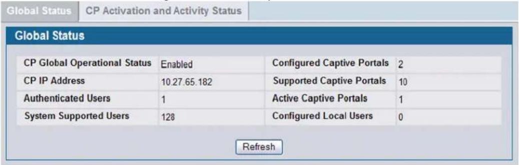
Table 73 describes the fields displayed on the CP Global Status page.
Table 73: Global Captive Portal Status
| Field Description | |
| CP Global Operational Status | Shows whether the CP feature is enabled. The default is disabled. |
| CP Global Disable Reason | If CP is disabled, this field indicates the reason for the CP to be disabled, which can be one of the following:None – CP is enabledAdministrator DisabledNo IPv4 AddressRouting Enabled, but no IPv4 routing interfaceThe default is Administrator Disabled.This field does not appear if the CP operational status is Enabled. |
| CP IP Address Shows the captive portal IP address. | |
| Authenticated Users | Shows the number of users currently authenticated to all captive portal instances on this switch. For the WIDS Controller, the number includes users authenticated on all switches in the peer group. The range is an integer. The default is 0. |
| System Supported Users | Shows the number of authenticated users that the system can support. This is a platform-defined constant. The range is an integer. The default is 128. |
| Configured Captive Portals | Shows the number of captive portal instances that have been administratively configured. The range is an integer. The default is 0. |
| Supported Captive Portals | Shows the number of supported captive portals in the system. This is a platform-defined constant. The range is an integer. The default is 10. |
| Active Captive Portals | Shows the number of captive portal instances that are operationally enabled. The range is an integer. The default is 0. |
| Configured Local Users | The number of users currently configured in the local database. The default is 0. See “Configuring Users in the Local Database” on page 178. |
Click Refresh to update the screen with the most current information.
Viewing CP Activation and Activity Status
The CP Activation and Activity Status page provides information about each CP configured on the switch.
Figure 90: CP Activation and Activity Status
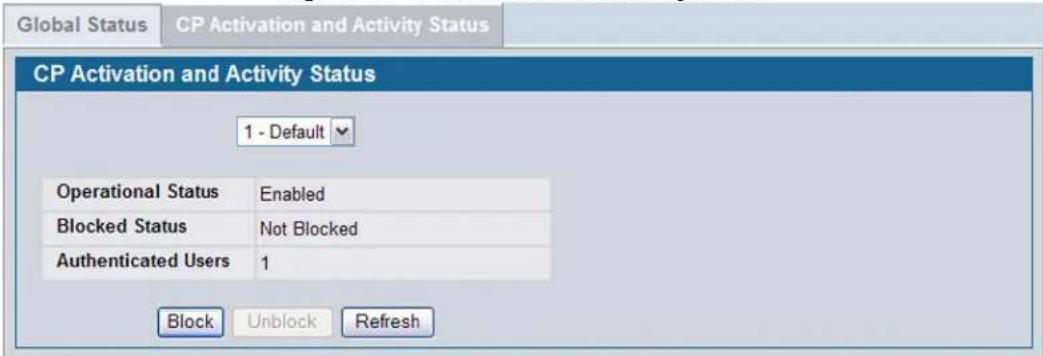
The CP Activation and Activity Status page has a menu that contains all captive portals configured on the switch. When you select a captive portal, the activation and activity status for that portal displays.
Table 74 describes the information that displays for each portal.
Table 74: CP Activation and Activity Status
| Field Description | |
| Operational Status Indicates whether the captive portal is enabled or disabled. | |
| Disable Reason | If the captive portal is disabled, then this field indicates the reason. The portal instance may be disabled for the following reasons:None - CP is enabled.Administratively DisabledRADIUS Authentication mode enabled, but RADIUS server is not defined.Not associated with any interfaces.The associated interfaces do not exist or do not support the CP capability. |
| Blocked Status | Indicates whether authentication attempts to the captive portal are currently blocked.Use theBlock and Unblockbuttons to control the blocked status. If the CP is blocked, users cannot gain access to the network through the CP. Use this function to temporarily protect the network during unexpected events, such as denial of service attacks.Note:The Blocked Status is the operational status and not the configured status. It does not persist over a reboot. By default, the status is unblocked.Block and Unblockare only available when the CP operational status is Enabled. |
| Authenticated Users | Shows the number of users that successfully authenticated to this captive portal and are currently using the portal. The range is an integer. The default is 0. |
The following buttons are available on the CP Activation and Activity page:
- Block—Click Block to prevent users from gaining access to the network through the selected captive portal.
- Unblock—If the Blocked Status of the selected captive portal is Blocked, click Unblock to allow access to the network through the captive portal.
- Refresh—Click Refresh to update the screen with the most current information.
Viewing Interface Activation Status
The Interface Activation Status page shows information for every interface assigned to a captive portal instance. Use the menus to select the portal or interface with the information you want to view.
Figure 91: Interface Activation Status
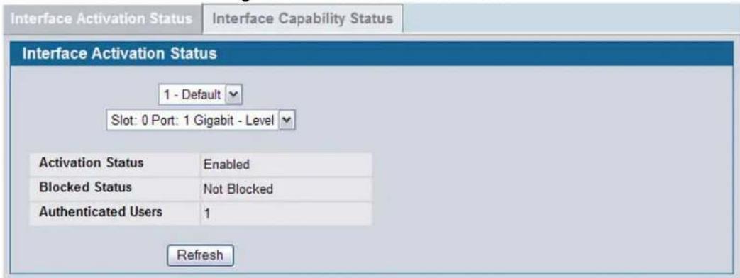
Table 75 describes the fields on the Interface Activation Status page.
Table 75: Interface Activation Status
| Field Description | |
| Operational Status | Shows whether the portal is active on the specified interface. Possible values are Enabled or Disabled. |
| Disable Reason | If the selected CP is disabled on this interface, this field indicates the reason, which can be one of the following:Interface Not AttachedDisabled by Administrator |
| Blocked Status | Indicates whether the captive portal is temporarily blocked for authentications. Possible values are:0 – Not blocked1 – BlockedThe default is 0. |
| Authenticated Users | Displays the number of authenticated users using the captive portal instance on this interface.The default is 0. |
Click Refresh to update the screen with the most current information.
Viewing Interface Capability Status
The Interface Capability Status page contains information about interfaces that can have CPs associated with them. The page also contains status information for various capabilities. Specifically, this page indicates what services are provided through the CP to clients connected on this interface. The list of services is determined by the interface capabilities.
Figure 92: Interface Capability Status
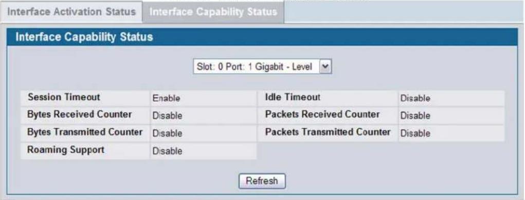
The menu contains all the physical interfaces and wireless interfaces available on the switch. Physical (wired) interfaces are identified by the Port Description that includes slot number, port number, and interface type. Wireless interfaces are identified by the wireless network number and SSID. Use the menu to select the interface with the information to display.
Table 76 describes the fields on the Interface Capability Status page.
Table 76: Interface and Capability Status
| Parameter Description | |
| Session Timeout | Shows whether the interface supports client session timeout. This attribute is supported on all interfaces. Possible values are Enable or Disable. The default is Enable. |
| Idle Timeout | Shows whether the interface supports a timeout when the user does not send or receive any traffic. Possible values are Enable or Disable. |
| Bytes Received Counter | Shows whether the interface supports displaying the number of bytes received from each client. Possible values are Enable or Disable. |
| Packets Received Counter | Shows whether the interface supports displaying the number of packets received from each client. Possible values are Enable or Disable. |
| Bytes Transmitted Counter | Shows whether the interface supports displaying the number of bytes transmitted to each client. Possible values are Enable or Disable. |
| Packets Transmitted Counter | Shows whether the interface supports displaying the number of packets transmitted to each client. Possible values are Enable or Disable. |
| Roaming Support | Shows whether the interface supports client roaming. Only wireless interfaces support client roaming. Possible values are Enable or Disable. |
Click Refresh to update the screen with the most current information.
Viewing the Client Summary
Use the Client Summary page to view summary information about all authenticated clients that are connected to the network through the captive portal. From this page, you can manually force the captive portal to disconnect one or more authenticated clients. The list of clients is sorted by client MAC address.
To view information about the clients connected to the D-Link Unified Access System through the captive portal, click Security > Captive Portal > Client Connection Status.
Figure 93: Client Summary
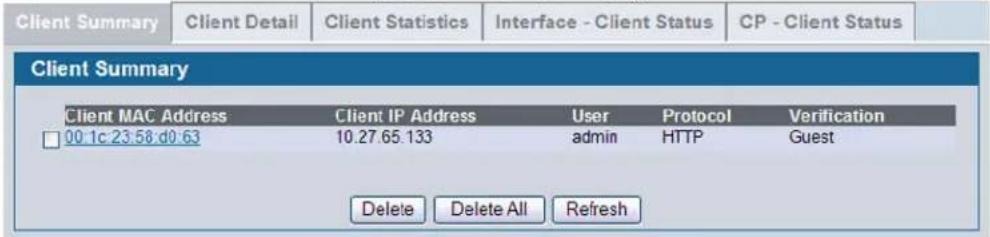
Table 77 describes the fields on the Client Summary page.
Table 77: Client Summary
| Field Description | |
| Client MAC Address | Identifies the MAC address of the client that has connected to the network through a captive portal. |
| Client IP Address Identifies the IP address of the client. The default is 0.0.0.0. | |
| User | Displays the user name (Local, RADIUS, or Guest ID) of the connected client. The range is 1-32 characters. |
| Protocol Shows the current connection protocol, which is either HTTP or HTTPS. | |
| Verification Shows the current account type, which is Guest, Local, or RADIUS. | |
- To force the captive portal to disconnect an authenticated client, select the check box next to the client MAC address and click Delete.
• To disconnect all clients from all captive portals, click Delete All. - Click Refresh to update the screen with the most current information.
Click the MAC address of a client to view additional status information.
Viewing Client Detail
The Client Detail page shows detailed information about each client connected to the network through a captive portal.
Figure 94: Client Detail
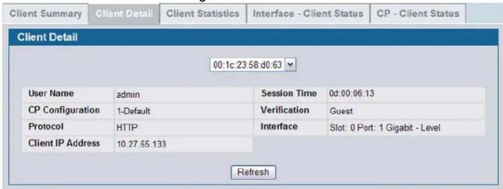
The menu lists each associated client by MAC address. To view status information for a client, select it from the list. Table 78 describes the fields on the Client Detail page.
Table 78: Client Detail
| Field Description |
| User Name Displays the user name (or Guest ID) of the connected client. |
| CP Configuration Identifies the name of the CP the client is using. The switch supports up to 10 CPs. |
| Protocol Shows the current connection protocol, which is either HTTP or HTTPS. |
| Client IP Address Identifies the IP address of the client. |
| Session Time Shows the amount of time that has passed since the client was authorized. |
| Verification Shows the current account type, which is Guest, Local, or RADIUS. |
| Interface Identifies the interface the client is using. |
Click Refresh to update the screen with the most current information.
Viewing the Client Statistics
Use the Client Statistics page to view information about the traffic a client has sent or received.
Figure 95: Client Statistics
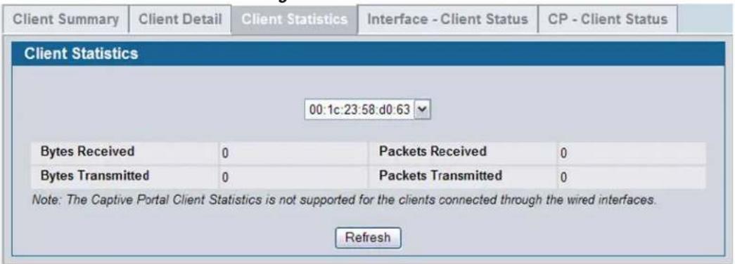
The menu lists each associated client by MAC address. To view statistical information for a client, select it from the list.
Table 79 describes the fields on the Client Statistics page.
Table 79: Client Interface Association Connection Statistics
| Field Description | |
| Bytes Transmitted | Total bytes the client has transmitted. The minimum collection time is 5 seconds. The switch may recalculate the collection interval after more APs become managed. |
| Bytes Received Total bytes the client has received | |
| Packets Transmitted Total packets the client has transmitted | |
| Packets Received Total packets the client has received | |
- Click Refresh to update the screen with the most current information.
Viewing the Client Interface Association Status
Use the Interface - Client Status page to view clients that are authenticated to a specific interface.
Figure 96: Interface - Client Status
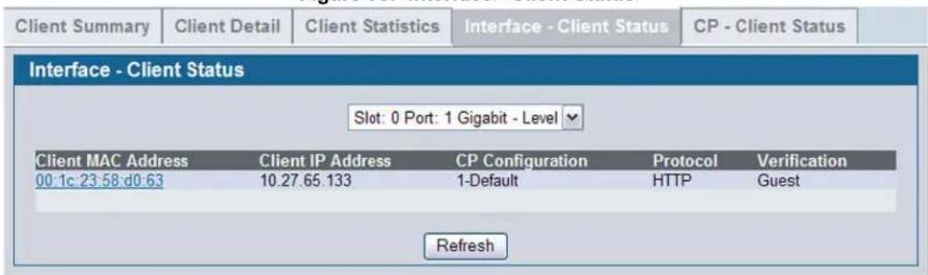
Software User Manual D-Link Unified Access System
02/15/2011
The menu lists each interface on the switch. To view information about the clients connected to a CP on this interface, select it from the list.
Table 80 describes the fields on the Interface - Client Status page.
Table 80: Interface - Client Status
| Field Description |
| Client MAC Address Identifies the MAC address of the client |
| Client IP Address Identifies the IP address of the client |
| CP Configuration Identifies the captive portal the client used to access the network |
| Protocol Shows the current connection protocol, which is either HTTP or HTTPS |
| Verification Shows the current account type, which is Guest, Local, or RADIUS. |
Click Refresh to update the screen with the most current information.
Viewing the Client CP Association Status
Use the CP - Client Status page to view clients that are authenticated to a specific CP configuration.
Figure 97: CP - Client Status
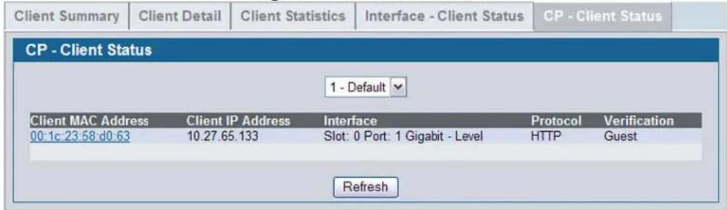
The menu lists each CP configured on the switch. To view information about the clients connected to the CP, select it from the list.
Table 81 describes the fields on the Client CP Association Status page.
Table 81: CP - Client Status
| Field Description | |
| Client MAC Address Identifies the MAC address of the client | |
| Client IP Address Identifies the IP address of the client | |
| Interface Identifies the interface the client used to access the network | |
| Protocol | Shows the current connection protocol, which is either HTTP or HTTPS |
| Verification | Shows the current account type, which is Guest, Local, or RADIUS. |
Click Refresh to update the screen with the most current information.
Use the SNMP Trap Configuration page to configure whether or not SNMP traps are sent from the Captive Portal and to specify captive portal events that will generate a trap.
All CP SNMP traps are disabled by default.
To configure SNMP trap settings for various captive portal features, click Security > Captive Portal > SNMP Trap Configuration.
Figure 98: SNMP Trap Configuration
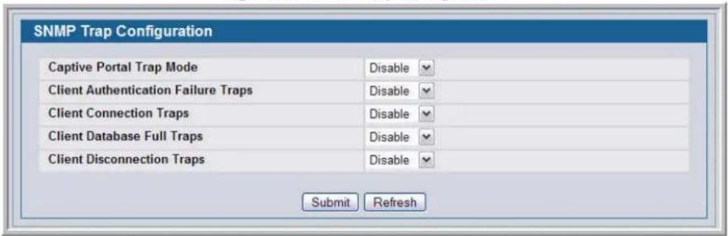
Table 82 describes the events that generate SNMP traps when the status is Enabled.
Table 82: SNMP Trap Configuration
| Field Description | |
| Captive Portal Trap Mode Choose one of the following captive portal trap modes:Select Enable to allow the SNMP agent on the switch to generate captive portal SNMP traps that are enabled.Select Disable to prevent the SNMP agent on the switch from generating any captive portal SNMP traps, even if they are individually enabled. | |
| Client Authentication Failure Traps | If you enable this field, the SNMP agent sends a trap when a client attempts to authenticate with a captive portal but is unsuccessful. |
| Client Connection Traps | If you enable this field, the SNMP agent sends a trap when a client authenticates with and connects to a captive portal. |
| Client Database Full Traps | If you enable this field, the SNMP agent sends a trap each time an entry cannot be added to the client database because it is full. |
| Client Disconnection Traps | If you enable this field, the SNMP agent sends a trap when a client disconnects from a captive portal. |
- To update the switch with the values on the screen, click Submit. If you want the switch to retain the new values across a power cycle you must perform a save.
• To update the screen with the most current information, click Refresh.
Section 11: Visualizing the Wireless Network
The WLAN Visualization component is an optional feature that graphically shows information about the wireless network. WLAN Visualization uses a Java applet to display D-Link Unified Switches, D-Link Access Points, other access points, and associated wireless clients. The WLAN Visualization tool can help you visualize where the APs are in relationship to the building.
You can upload one or more custom images to create a background for the graph. Then, you place the WLAN components discovered by the switch on the graph to help provide a realistic representation of your wireless network. From each object on the WLAN Visualization graph, you can access information about the object and links to configuration pages on the Web interface.
This chapter contains the following sections to help you manage the WLAN Visualization component of the D-Link Unified Access System:
- "Importing and Configuring a Background Image"
- "Setting Up the Graph Components"
- "Understanding the Menu Bar Options"
- "Managing the Graph"
Figure 99 shows an example of a floor plan with a D-Link Unified Switch that manages two APs. The figure also shows two switches and a rogue AP.
Figure 99: Sample WLAN Visualization
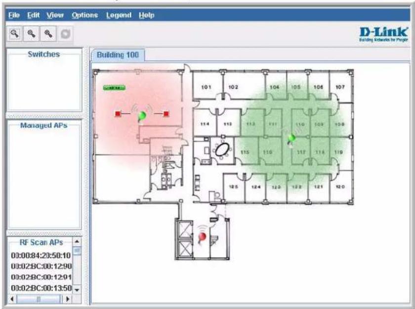
Importing and Configuring a Background Image
By default, the WLAN Visualization graph does not have a background image. You can upload one or more images, such as your office floor plan, to provide a site context and site related information.
Images that you upload should be in one of the following two file formats:
• GIF (Graphics Interchange Format)
• JPG (Joint Photographic Experts Group)
Additionally, we recommend that you do not use color images since the WLAN components might not show up as well.
To load an image onto the switch to use as a background for the WLAN Visualization graph, use the following procedures:
1 Click WLAN Visualization > Download Image.
2 Click Browse to navigate to the file location.
3 Select the file to upload and click Start File Transfer.
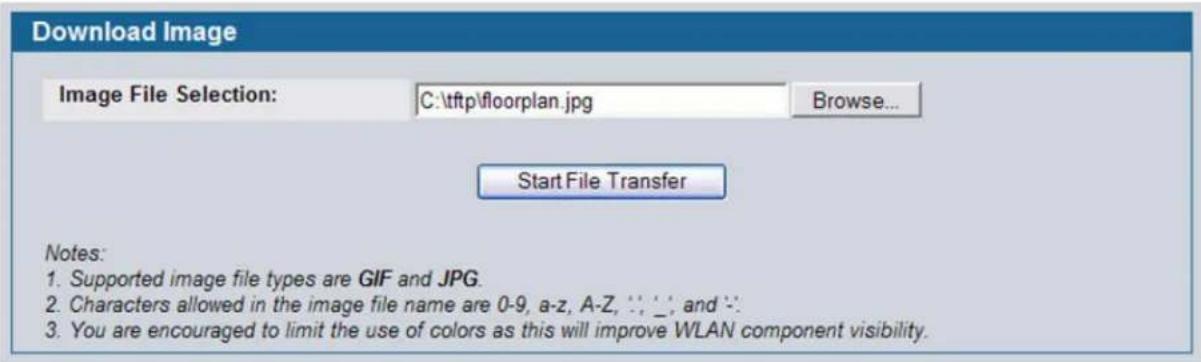
Once you upload an image file and save the running configuration, the image remains on the switch and you can assign it to an existing graph using the WLAN Visualization application.
SETTING UP THE GRAPH COMPONENTS
To start the WLAN Visualization tool, click WLAN Visualization > Launch... This opens a new browser window and starts the Java applet.
The first time you launch the WLAN Visualization tool, there is no background image, and all discovered WLAN components are ungraphed. The screen is split into two panes. The left pane has 3 container views that are used to hold un-graphed components. The right pane is an area where graph definitions are shown. This graph pane is initially blank and must be defined before WLAN components can be placed.
Creating a New Graph
To create a new graph and load the background image, launch the WLAN Visualization tool and use the following steps.
1 From the WLAN Visualization menu bar, click Edit > New Graph.
The New Graph Definition dialogue box opens.
2 Enter a name to identify the graph and select the image to use as the background.
For information about how to upload an image to use as a graph background, see "Importing and Configuring a
Background Image" on page 191.
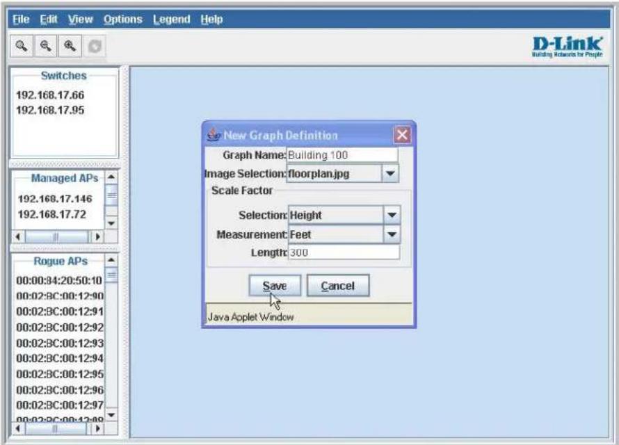
3 Enter the represented length for one of the graph dimensions (height or width).
Use the Selection and Measurement menus to specify whether the length is the height or width, and whether it is in meters or feet.
The length you enter determines the scale of the background image in relation to the network components. The scale of the background image affects the way the WLAN Visualization tool presents the radio frequency (RF) coverage of the access points, so it is important to be as accurate as possible when you specify the length.
For example, in the following graphs, the background image is the same, and the APs are in the same location in both images. The only difference between the images is that one image was set up with a graph definition length of 200 feet,
and the other image was set up with a graph definition length of 800 feet.
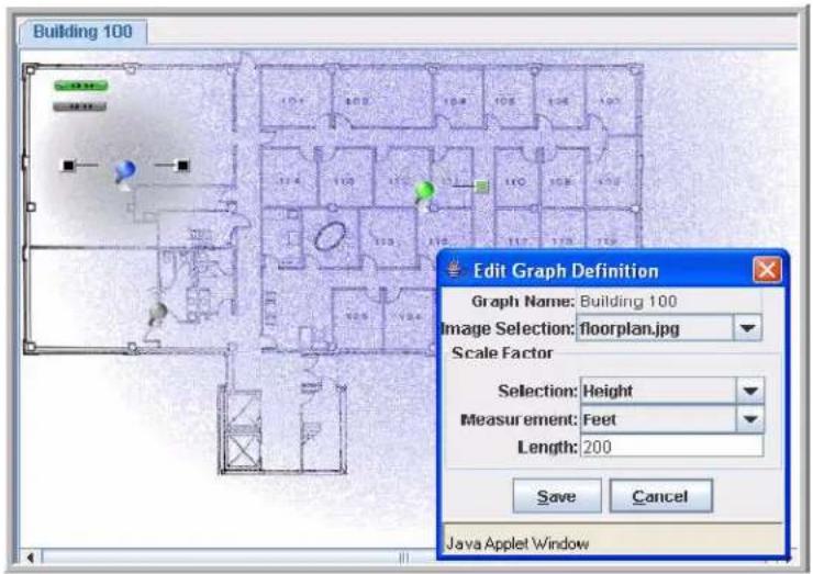
Graph Definition
Length = 200'
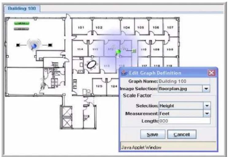
Graph Definition
Length = 800'
4 Click Save to complete the graph setup.
The background you uploaded to the switch appears in the background of the graph.
You can create multiple graphs. For example, if your network spans multiple floors or buildings, you might have a graph for each area. Additional graphs that you create appear as tabs at the top of the graph panel, as Figure 100 shows.
Figure 100: Multiple Graphs
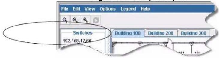
To create additional graphs, repeat the steps in this section.
Graphing the WLAN Components
The WLAN Visualization tool automatically shows the WLAN components that the switch has discovered.
The panel lists the following component types:
• Switches (Unified Switch and peer Unified Switches)
- Managed Access Points
• RF Scan Access Points
These components appear in the panel on the left until you drag them onto the graph. From the View menu, you can choose to view the components in a list view, which shows all three types of components in the left panel or in a tabbed view, which shows one type of component at a time, organized by tabs. Figure 101 shows an example of a list view and a tabbed view of the same components. Access points are listed by location or MAC address, and switches are listed by IP address.
Figure 101: List View and Tabbed View
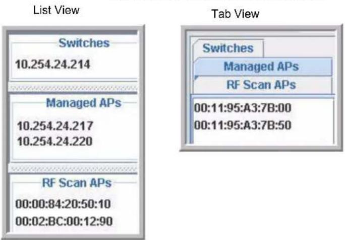
Wireless clients do not appear in the panel. Instead, they are automatically graphed based on their association with (or disassociation from) a D-Link Access Point that is graphed.
If you mouse-over an ungraphed component, a tool tip appears to provide additional information about the ungraphed component, as shown in Figure 102.
Figure 102: Component Tool Tip
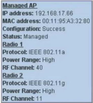
To graph a component that is listed in the panel, click the component and drag it to the location in the graph that represents the physical location of the component in the building. Once you move a switch or access point to the graph area, it is removed from the panel.
Hold the SHIFT or CTRL key to select multiple components, then right-click a selected component to drag the components onto the graph at the same time.
Figure 103: Graphed Components
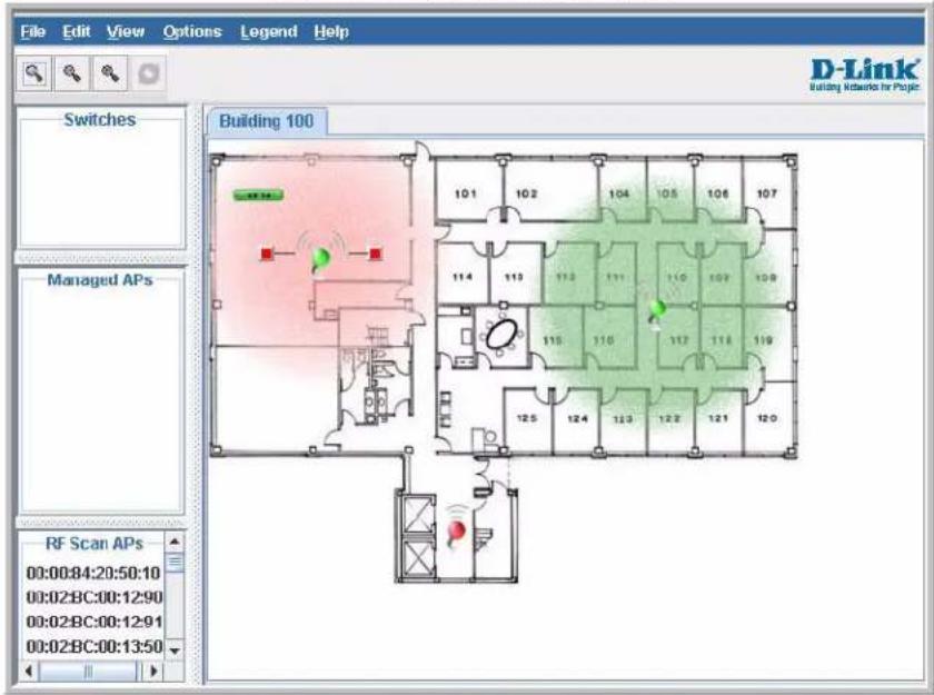
To remove a component from the graph, right-click the component, the select Edit > Un-Graph.
UNDERSTANDING THE MENU BAR OPTIONS
The following table provides an overview of the menu items available in the WLAN Visualization tool.
Table 83: WLAN Visualization Menu Bar Options
| Menu Item Description | |
| File | |
| Force Refresh Resynchronizes the Java client application. If you edit the graph, you can force a refresh to manually update the view. | |
| Reconnect and Refresh Disconnects the client application from the switch and re-connects it. | |
| Exit Exits the WLAN Visualization application. | |
| Edit | |
| New Graph Opens a window that allows you to create and configure a new graph, including the name, background image, and scale factor for the graph. | |
| Edit Graph Opens the window for an existing graph. You can change the background image or graph scale. To change the name of the graph, you must create a new graph. | |
| Delete Graph Deletes the active graph. When you select this item, a dialogue box appears to confirm that you want to delete the graph. | |
| Image Management Lists the available background images and allows you to delete any available image. | |
| View | |
| Ungraphed Components Allows you to change the view of the ungraphed components in the panel on the left:Tab View—Shows one type of component at a time, organized by tabs.List View—Shows all three types of components in the left panel.Figure 101 on page 195 shows the difference between the tab view and list view. | |
Table 83: WLAN Visualization Menu Bar Options
| Menu Item Description | |
| AP Power Display Select the power range image to display for a managed AP: | |
| Disable Power Display—The power range image is not displayed | |
| Show 802.11 a—Shows the transmit power for all managed APs that have a radio operating in 802.11a mode. | |
| Show 802.11 b/g—Shows the transmit power for all managed APs that have a radio operating in 802.11 b/g mode. | |
| The size of the power range image is based on the transmit power for the radio, which can be low, medium, or high. The size of the power range image also depends on the actual scale factor of the current background image. | |
| If the AP has two radios that are configured in the same mode, two power range images are displayed. | |
| Note: The color of the power range image is based on the assigned channel of the associated radio. | |
| If two APs use the same channel (or channels that are close together) and are within each other's transmission range, the APs will interfere with each other and wireless clients will experience poor WLAN performance. To reduce interference, you can take one of the following steps: | |
| Reduce the transmit power on the APs. | |
| Physically place the APs further apart. | |
| Use the automatic channel adjustment algorithm on the APs or statically set the channels so they are non-interfering channels. | |
| Caution! Power ranges are for illustrative purposes only. The actual power distribution varies based on factors such as office wall propagation and background RF noise. | |
Options
| Show Managed APs Controls whether to display D-Link Access Point on the graph. Clearing the check box hides but does not un-graph the objects. | |
| Show RF Scan APs Controls whether to display the APs detected through the RF scan. Clearing the check box hides but does not un-graph the objects. | |
| Show Managed AP Clients Controls whether to display wireless clients associated with managed APs. Clearing the check box hides but does not un-graph the objects. | |
| Legend | |
| Images Shows the icons associated with each WLAN component on the graph. | |
| Channel Color Maps the color of the power transmission image to the channel that the radio is using for transmission. | |
| Help | |
| Table of Contents Opens a new HTML window to display the table of contents for the WLAN online Help. | |
Legend Menu
The items in the Legend menu contain information about the icons and colors that appear on the graph.
The Images menu item shows the icons that represent the WLAN components on the graph.
Figure 104: Legend
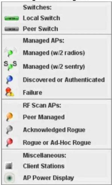
As the legend shows, the Managed AP icon can be blue, green, or red, depending on the status of the AP:
- Blue—The AP has been discovered and by the switch, but it is in a transitional state. The AP could be waiting to be authenticated, or it has been validated and authenticated but not configured.
- Green—The AP profile configuration has been applied to the AP, and it is operating in managed mode.
- Red—The switch has lost contact with the AP, the AP is being reset, or the AP has experienced an authentication failure.
When a radio is operating in Sentry Mode, the antenna on the AP icon is replaced by the letter "S" as Figure 105 shows.
Figure 105: Sentry Mode - Detailed View
For radios in sentry mode, the AP power display image around the AP is gray.
The Channel Color legend maps the color of the power display image to the channel that the image color represents. The color corresponds to the channel that the radio is using for transmission. The available channels depend on the mode and country of operation.
Figure 106: Channel Colors
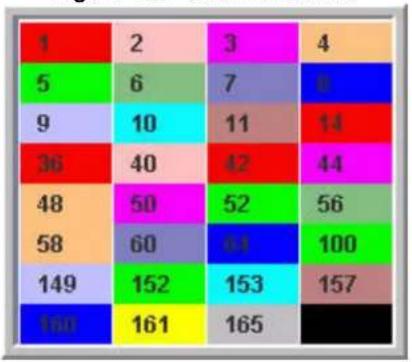
heatmap
| | 1 | 2 | 3 | 4 | |---|---|---|---|---| | 1 | | | | | | 5 | | 6 | 7 | 8 | | 9 | | 10 | 11 | 14 | | 36 | | 40 | 42 | 44 | | 48 | | 50 | 52 | 56 | | 58 | | 60 | 54 | 100 | | 149 | | 152 | 153 | 157 | | 160 | | 161 | 165 | | The values in the matrix are explicitly labeled as '1', '2', '3', '4', '5', '6', '7', '8' respectively. The values in the matrix are represented by colored cells (color intensity) and are not explicitly labeled on the axes.To view the channel that a radio is using, you can mouse-over the managed AP to activate the tool tip. The tool tip displays general information about the AP, including the channel that each radio uses.
Figure 107: Tool Tip for Radio Managed AP Information
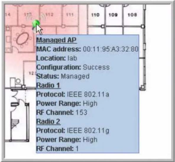
You can also right-click the object to access a variety of information, which the next section describes.
MANAGING THE GRAPH
After you place a component on the graph, you can right-click the component to learn more information about it, un-graph it, or link to a page on the Web UI to manage or monitor the component.
Figure 108: Wireless Component Attributes
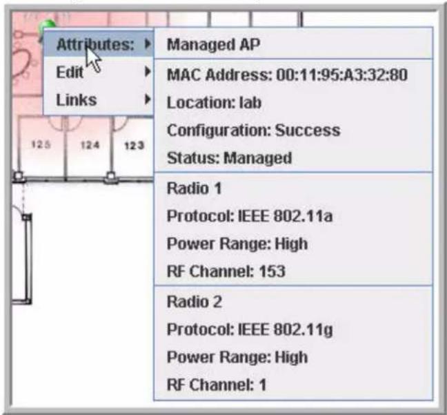
Table 84 lists the attribute and link information available from each component.
Table 84: Component Information
| Component Attributes Links/Commands | |
| Switch IP Address Basic Setup | RF ManagementGlobal Status/Statistics |
| Peer Switch IP Address Peer Switch Status | |
| Managed AP MAC Address | Configuration |
| Location | AP Profile Configuration |
| Configuration | Valid AP Configuration |
| Status—Managed | Management |
| Radio—1 or 2 | Radio |
| Protocol—802.11b/g or 802.11a | Software Download |
| Power Range—Low, Medium, or High | Debug |
| RF Channel—Depends on channel plan | Status and Statistics |
| Sentry Mode (if enabled) | Managed AP Status DetailRadio Status and StatisticsCommand: AP Reset |
Table 84: Component Information
| Component Attributes Links/Commands | |
| Other AP MAC Address | Status |
| Status—Rogue, Standalone, Peer Managed, or Acknowledged AP | Commands: |
| Manage | |
| RF Channel | Acknowledge |
| Wireless Client MAC Address | Associated Client Status Detail |
| Radio—1 or 2 | Command: Disassociate |
| RF Channel—Depends on channel plan | |
Appendix A: D-Link Unified Access System Default Settings
This chapter identifies the default values for the D-Link Unified Switch, the default D-Link Access Point settings, and the default AP Profile setting that the switch assigns to the AP after it is discovered and authenticated (when the AP uses the default profile).
DEFAULT D-LINK UNIFIED SWITCH SETTINGS
Table 85 shows the default settings for the D-Link Unified Switch.
Table 85: Switch Defaults
| Feature Default | |
| System Information | |
| User Name admin | |
| Password None | |
| Network Information | |
| DHCP Client Disabled | |
| Network Configuration Protocol None | |
| IP Address 10.90.90.90 | |
| Subnet Mask 255.0.0.0 | |
| 802.1Q Enabled | |
| Management VLAN ID 1 | |
| Untagged VLAN ID 1 | |
| Spanning Tree Protocol | Enabled |
| WLAN Information | |
| Unified Switch Mode | Enabled |
| AP Authentication | Disabled |
| AP Validation | Local |
| Country Code | US |
| Default Profile Name | Default |
| Peer Switch Group ID | 1 |
| L2 (VLAN) /L3 (IP) Discovery | Enabled |
| SNMP Traps | Disabled |
| Client Roam Timeout | 30 seconds |
| Ad Hoc Client Status | 24 hours |
| AP Failure Status | 24 hours |
| Client Failure Status | 24 hours |
| RF Scan Status | 24 hours |
DEFAULT D-LINK ACCESS POINT SETTINGS
Table 86 shows the default D-Link Access Point settings. The settings are the same for DWL-3500AP, DWL-8500AP, and DWL-8600AP.
Table 86: Default AP Settings
| Feature Default | |
| System Information | |
| User Name admin | |
| Password admin | |
| Network Information | |
| DHCP Client Enabled | |
| Management IP Address 10.90.90.91 (If not assigned by DHCP) | |
| Subnet Mask 255.0.0.0 (If not assigned by DHCP) | |
| Management VLAN 1 | |
| Untagged VLAN 1 | |
DEFAULT D-LINK ACCESS POINT PROFILE SETTINGS
Table 87 shows the AP settings for the default profile. By default, when a D-Link Access Point associates with the switch, the settings in this table are assigned to the AP upon successful AP validation.

Note: Only the settings for Radio 2 will be applied to DWL-3500APs if they are managed by a DWS-3000 switch.
Table 87: AP Profile Default Settings
| Feature Default | |
| Radio Settings | |
| Radio (1 and 2) State On | |
| Radio 1 IEEE 802.11 Mode 802.11a | Note: If the AP operates in a regulatory domain where 802.11a is not supported, the radio is disabled and no mode is configured. |
| Radio 2 IEEE 802.11 Mode 802.11b/g | |
| Super AG Disabled | |
| RTS Threshold 2347 bytes | |
| Load Balancing | Disabled |
| Load Utilization | 60% |
| RF Scan Other Channels | Disabled |
| RF Scan Interval | 60 seconds |
| RF Scan Sentry | Disabled |
| Station Isolation | Disabled |
| Feature | Default |
| RF Scan Sentry Channels Disabled | |
| RF Scan Duration 10 milliseconds | |
| Transmit Lifetime 512 milliseconds | |
| Receive Lifetime 512 milliseconds | |
| Channel Bandwidth 20 MHz | |
| Maximum Clients 256 | |
| DTIM Period 10 beacons | |
| Beacon Period 100 milliseconds | |
| Automatic Channel Enabled | |
| Limit Channels Disabled | |
| Automatic Power Enabled | |
| Initial Power 100 | |
| Antenna Diversity | Primary |
| Fragmentation Threshold | 2346 bytes |
| Short Retries | 7 |
| Long Retries | 4 |
| 802.11n Protection | Auto |
| Primary Channel | Lower |
| Rate Sets Supported (Mbps) | IEEE 802.1a: 54, 48, 36, 24, 18, 12, 9, 6IEEE 802.1g: 54, 48, 36, 24, 18, 12, 11, 9, 6, 5.5, 2, 1IEEE 802.1b: 11, 5.5, 2, 1Atheros Dynamic Turbo 5 GHz: 108, 96, 72, 48, 36, 24, 18, 12 |
| Rate Sets (Mbps) (Basic/Advertised) | IEEE 802.1a: 24, 12, 6IEEE 802.1g: 11, 5.5, 2, 1IEEE 802.1b: 2, 1Atheros Dynamic Turbo 5 GHz: 48, 24, 12 |
| Virtual Access Point and Network Settings | |
| Status | VAP0 is enabled on both radios, all other VAPs disabled |
| Network Name (SSID) | dlink1 |
| VLAN | 1 |
| Hide SSID | Disabled |
| L3 Tunnel | Disabled |
| Security Mode | Open System |
| MAC Authentication | Disabled |
| RADIUS IP Address | Use Profile (Global) |
| RADIUS Accounting | Disabled |
| Other Settings | |
| QoS | Enabled |
| WMM | Enabled |
DEFAULT CAPTIVE PORTAL SETTINGS
Table 88 shows the default captive portal settings.
Table 88: Default Captive Portal Settings
| Feature Default | |
| Global Configuration | |
| Operational Status Enabled | |
| Additional HTTP Port None | |
| Peer Switch Statistics Reporting Interval 120 seconds | |
| Authentication Session Timeout 600 seconds | |
| CP Configuration | |
| Status Enabled | |
| Configuration Name None | |
| Protocol Mode HTTP | |
| Verification Mode Guest | |
| User Group None | |
| URL Redirect Mode Disabled | |
| Session Timeout 0 (unlimited) | |
| Idle Timeout 0 (unlimited) | |
| Languages English | |
Appendix B: Configuring the External RADIUS Server
You can store the Valid AP configuration on a local database on the D-Link Unified Switch or on an external RADIUS server. This appendix describes the attributes you must define for each feature to setup their configuration on the RADIUS server.
One important reason why you might define the AP information on the RADIUS server rather than on the switch is to allow peer switches to obtain the data from a single source rather than having to define it on each switch.
CONFIGURING RADIUS SETTINGS FOR ACCESS POINTS
Since the AP is identified by its physical MAC address, you must add a RADIUS entry for each AP with the User-Name attribute set to the MAC address. Table 89 indicates the attributes to configure in the RADIUS server entry for each AP. Add the vendor-specific attributes by using the D-Link vendor ID (6132) and the identifier D-Link-Wireless-AP-* (where "*" represents the attribute name).

Note: This appendix does not describe RADIUS configuration for AP network authentication using 802.1X. This feature is separate from a valid AP configuration entry. The edge device that connects to the AP performs the network authentication. The edge device might not be the Unified Switch.
Table 89: RADIUS Attributes for the Access Point
| RADIUS Server Attribute Description Range Usage | |||
| User-Name (1) Ethernet Address of the AP. Valid Ethernet MAC Address Required | |||
| User-Password (2) A fixed password used to lookup an AP entry. | 8-63 characters, default NOPASSWORD | Required | |
| Vendor-Specific (26) Location | A description for the AP, often based on its location. | 1-32 characters Optional | |
| Vendor-Specific (26) Mode | Indicates whether this AP is managed by the switch, by an administrator, or is a rogue AP. | WS Managed (1) Standalone (2) Acknowledged Rogue (3) | Required |
| Vendor-Specific (26) Profile-ID | If AP is managed by a switch, the ID of the configuration profile for this AP. | 1-16 Required if mode is | WS managed. |
| Vendor-Specific (26) Switch-IP | If there is more than one WS using this RADIUS server, indicates the IP address of the WS to managed this AP. | Valid IP Address Optional | |
| Vendor-Specific (26) Radio-1-Chan | Indicates a fixed channel for the radio. | Valid channels depend on the regulatory domain (country-code) and the configured mode for that radio in the assigned AP profile. If the channel is not valid, its ignored. | Optional, if defined and valid will override auto channel configuration |
| Vendor-Specific (26) Radio-2-Chan | 0 indicates automatic channel assignment. | ||
| Vendor-Specific (26) Radio-1-Power | Indicates a fixed power setting for the radio. | 0, 1-100 percent0 indicates automatic power assignment. | Optional, if defined and valid will override auto power configuration |
| Vendor-Specific (26) Radio-2-Power | Indicates a fixed power setting for the radio. | 0, 1-100 percent0 indicates automatic power assignment. | Optional, if defined and valid will override auto power configuration |
When you do not require authentication between the APs and the RADIUS server, the switch uses the password "NOPASSWORD" in communications between the RADIUS client on the switch and the RADIUS server. The RADIUS client on the switch uses this password when it retrieves entries from the server. When you do require AP authentication, the password for AP authentication to the Unified Switch (separate from and in addition to AP authentication to the network) will be in this field.
FREERADIUS SERVER CONFIGURATION EXAMPLE
FreeRADIUS is an open source RADIUS server that you can download free from
http://www.freeradius.org. The example in this section describes the files you need to configure in order to authenticate the D-Link Unified Switch and the D-Link Access Point with the RADIUS server and to configure the Valid AP settings in the RADIUS database.
Configuring RADIUS Clients
If you require the D-Link Unified Switch or D-Link Access Points to authenticate themselves with the RADIUS server, you must configure client entries for the devices in the RADIUS server's etc/raddb/clients.conf file.
The entry contains the IP address of the client, the shared secret, and a nickname (or DNS name) for the device.
The following entry in the clients.conf file is for a switch with the following information:
• IP address: 192.168.30.249
- Subnet mask: 255.255.255.0
- Shared secret: wireless
• DNS name: wireless-sw1
The following code shows the format of the client entry in the clients.conf file:
client 192.168.30.249/24 {
    secret = wireless
    shortname = wireless-swl
}
Creating and Including an Attribute Dictionary
You configure attributes in an attribute dictionary so that you can assign the attributes and values to an access point when you configure it in the Valid AP database on the RADIUS server. For example, to assign a location to an access point, the attribute you define has the following format:
ATTRIBUTE
D-Link-Wireless-AP-Location
101
string D-Link
The fields in the attribute are as follows:
- Attribute—type of entry
• D-Link-Wireless-AP-Location—name of the attribute
• 101—ID number assigned to the attribute; you must use this number when you configure the location attribute
• string—type of data for the attribute
• D-Link—vendor-specific name for the attribute
The following VALUE field defines one of the values you can assign to an AP for the AP Mode.
VALUE D-Link-Wireless-AP-Mode WS-Managed 1
The VALUE fields are as follows:
- VALUE—type of entry
• D-Link-Wireless-AP-Mode—name of the attribute - WS-Managed—value for the attribute
• 1—name-to-number mapping for the attribute
The following code is an example of the D-Link attribute dictionary. The code shows the complete file. You can create your own dictionary and configure the attributes and values that your WLAN requires. The VENDOR field has the vendor-specific attribute name-to-number mapping.
After you create the file, save the dictionary in the etc/raddb directory with a file name dictionary.
VENDOR D-Link 6132
#
<h1 id="d-link-vendor-specific-extensions">D-Link Vendor Specific Extensions</h1>
#
#
ATTRIBUTE D-Link-Wireless-AP-Location 101 string D-Link
ATTRIBUTE D-Link-Wireless-AP-Mode 102 integerD-Link
ATTRIBUTED-Link-Wireless-AP-Profile-ID 103 integer D-Link
ATTRIBUTE D-Link-Wireless-AP-Switch-IP 104 ipaddr D-Link
ATTRIBUTE D-Link-Wireless-AP-Radio-1-Chan 105 integer D-Link
ATTRIBUTE D-Link-Wireless-AP-Radio-2-Chan 106 integer D-Link
ATTRIBUTE D-Link-Wireless-AP-Radio-1-Power 107 integer D-Link
ATTRIBUTE D-Link-Wireless-AP-Radio-2-Power 108 integer D-Link

VALUE D-Link-Wireless-AP-Mode WS-Managed 1
VALUE D-Link-Wireless-AP-Mode Standalone 2
VALUE D-Link-Wireless-AP-Mode Rogue 3
VALUE D-Link-Wireless-AP-Radio-1-Chan Auto 0
VALUE D-Link-Wireless-AP-Radio-2-Chan Auto 0
VALUE D-Link-Wireless-AP-Radio-1-Power Auto 0
VALUE D-Link-Wireless-AP-Radio-1-Power Minimum 1
VALUE D-Link-Wireless-AP-Radio-1-Power Maximum 100
VALUE D-Link-Wireless-AP-Radio-2-Power Auto 0
VALUE D-Link-Wireless-AP-Radio-2-Power Minimum 1
VALUE D-Link-Wireless-AP-Radio-2-Power Maximum 100
After you create an attribute dictionary file, you must insert an INCLUDE statement into the main file dictionary for the FreeRADIUS server.
The main dictionary is etc/raddb/dictionary. The following example shows an INCLUDE statement for the D-Link attribute dictionary called dictionary.D-Link.
\$INCLUDE dictionary.D-Link
Adding Access Points to the Valid AP Database
You use the attributes you define in the dictionary file to configure the settings for an access point in the Valid AP database on the RADIUS server. The file you configure is the etc/raddb/users file. The following code is an example of a database entry for an AP with the MAC address 00:11:95:a3:32:80.

Note: In the FreeRADIUS database, the MAC address is case sensitive, and the octets must be separated by hyphens.
00-11-95-a3-32-80 Auth-Type := Local, User-Password=="NOPASSWORD"
D-Link-Wireless-AP-Mode = WS-Managed,
D-Link-Wireless-AP-Location = "Lobby AP",
D-Link-Wireless-AP-Profile-ID = 1,
D-Link-Wireless-AP-Switch-IP = 192.168.30.4,
D-Link-Wireless-AP-Radio-1-Chan = Auto,
D-Link-Wireless-AP-Radio-2-Chan = Auto,
D-Link-Wireless-AP-Radio-1-Power = Auto,
D-Link-Wireless-AP-Radio-2-Power = Auto
CONFIGURING RADIUS SETTINGS FOR WIRELESS CLIENTS
You can configure D-Link Access Points to use 802.1X authentication on the RADIUS server to allow or deny specific users on client stations access to the wireless network. If you enable 802.1X authentication, the client entry on a RADIUS server can support user-based VLANs and subnet assignments for IP tunneling. Table 90 shows the attributes to set for wireless clients within the RADIUS server.
Table 90: RADIUS Attributes for Wireless Clients
| RADIUS Server Attribute | Description | Range | Usage |
| User-Name (1) – 1-32 characters Required | |||
| User-Password (2) – 1-128 characters Required | |||
| Tunnel-Medium-Type (65) – 802 Optional | |||
Configuring RADIUS for Client MAC Authentication
You can configure the AP to use RADIUS-based MAC authentication to allow or deny specific client stations access to the wireless network. Although this method is less secure than 802.1X, you can use it for client stations that do not support 802.1X.
The addresses you enter are either allowed or denied based on the global default action within the AP profile.
Table 91 indicates the attributes that you configure in the RADIUS server entry.
Table 91: RADIUS Attributes for Wireless Client MAC Authentication
| RADIUS Server Attribute | Description | Range | Usage |
| User-Name (1) Ethernet Address of the client station. Valid Ethernet MAC Address. | Required | ||
| User-Password (2) A fixed password used to lookup a client MAC entry. | NOPASSWORD Required | ||
FREERADIUS EXAMPLE FOR WIRELESS CLIENT CONFIGURATION
You can use an external RADIUS server, such as a server running FreeRADIUS, to authenticate users who attempt to connect to an access point. The authentication is based on the username and password, and not the wireless client used for access. The RADIUS server can also assign the user to a VLAN after he or she is authenticated by the server.
In addition to user-based authentication, you can configure MAC-based authentication to allow or deny wireless clients access to the AP based on the MAC address of the client.
Configuring User-Based Authentication and Dynamic VLANs
You can configure an entry in the external RADIUS server to pass a users credentials to the access point and to dynamically assign the user to a VLAN.
Dynamic VLANs allow you to assign a user to a VLAN, and switches dynamically use this information to configure the port on the switch automatically. Selection of the VLAN is usually based on the identity of the user. The RADIUS server informs the access point of the selected VLAN as part of the authentication. This setup enables users of Dynamic VLANs to move from one location to another without intervention and without having to make any changes to the switches.
If you use an external RADIUS server to manage VLANs, you configure the server to use Tunnel attributes in Access-Accept messages in order to inform the access point about the selected VLAN. These attributes are defined in RFC 2868 and their use for dynamic VLAN is specified in RFC 3580.
The VLAN attributes defined in RFC3580 are as follows:
• Tunnel-Type = VLAN (13)
• Tunnel-Medium-Type = 802
• Tunnel-Private-Group-ID = VLANID
To create a user and assign the user to a particular VLAN by using FreeRADIUS, open the etc/raddb/users file, which contains the user account information, and add for the new user.
The following example shows the entry for a user in the users file. The username is "johndoe," the password is "test1234." The user is assigned to VLAN 77.
johndoe Auth-Type: = EAP, User-Password == "test1234"
Tunnel-Type = "VLAN",
Tunnel-Medium-Type = "IEEE-802",
Tunnel-Private-Group-ID = "77",
Tunnel-Type and Tunnel-Medium-Type use the same values for all stations. Tunnel-Private-Group-ID is the selected VLAN ID and can be different for each user.

Note: Do not use the management VLAN ID of the AP for the value of the Tunnel-Private-Group-ID. The dynamically-assigned RADIUS VLAN cannot be the same as the management VLAN. If the RADIUS server attempts to assign a dynamic VLAN that is also the management VLAN, the AP ignores the dynamic VLAN assignment, and a newly associated client is assigned to the default VLAN for that VAP. A re-authenticating client retains its previous VLAN ID. The limitation is only on the DWL-8500APs. When the DWL-8600APs are managed by the DWS-3000 switch, the limitation does not apply.
The dynamically-assigned RADIUS VLAN cannot be the same as the AP's management VLAN. If the RADIUS server attempts to assign a dynamic VLAN to a client that associates with an AP with that VLAN as the management VLAN, the AP ignores the dynamic VLAN assignment and a newly associated client is assigned to the default VLAN for that VAP. A re-authenticating client retains its previous VLAN ID.
The default management VLAN ID for all APs is 1. The only way to change an AP's management VLAN ID is by using the set management vlan-id command from the CLI.
After you change the etc/raddb/users file, you must restart the RADIUS server daemon to apply the changes.
Configuring MAC Authentication
For each network, you can configure whether to use a local or RADIUS database for client MAC authentication. To use RADIUS-based MAC authentication for wireless clients, you add an entry for each client in the etc/raddb/users file. If the default action for MAC Authentication on the switch is set to "Allow," only clients that have an entry in the users file are allowed access to the network through the AP. If the default action is set to "deny" the clients with a MAC address in the users file cannot authenticate with the AP.
The following line is an example of an entry for a client in the etc/raddb/users file.
00-0F-FE-1C-F2-67 Auth-Type: = Local, User-Password == "NOPASSWORD"

Note: The password is always NOPASSWORD, and the MAC address of the client uses hyphens, not colons.
Appendix C: L3 Roaming Example
L3 Roaming can be achieved by using VLAN trunking (associate the SSID with a VLAN) or by using an L3 Tunnel (associate the SSID with a tunnel subnet). The example in this appendix describes how to configure a D-Link Unified Switch by using an L3 Tunnel for a network that needs L3 roaming capabilities.
This example contains information about the following features, which might be required to use L3 tunneling on your WLAN:
- "Configuring the WLAN and Tunnel Interfaces"
- "Configuring the L3 Tunnel Network"
- "Configuring DHCP Relay and the DHCP Server"
CONFIGURING THE WLAN AND TUNNEL INTERFACES
The following figure shows an example of a network that uses L3 tunnels to support wireless roaming. The subnet that all clients will use for L3 roaming is 192.168.60.0/24. The configuration examples in the rest of this appendix use the network information in this figure.
Figure 109: Example of a Network with L3 Tunnel Subnet
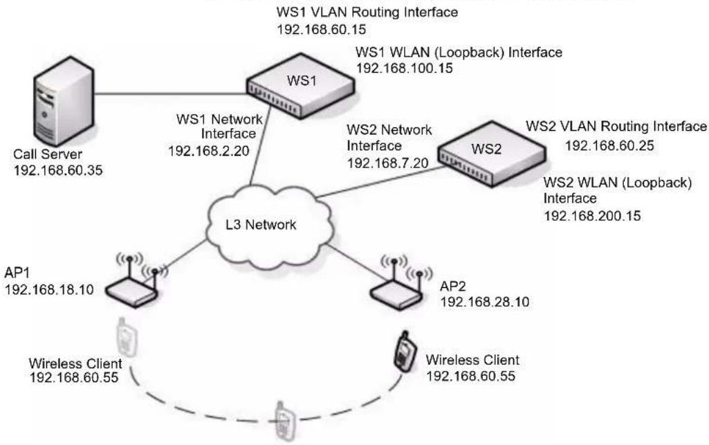
flowchart
graph TD
    WS1["WS1"] -->|WS1 Network Interface 192.168.2.20| L3["L3 Network"]
    WS1 -->|WS1 VLAN Routing Interface 192.168.60.15| WS2["WS2"]
    WS1 -->|WS1 WLAN (Loopback) Interface 192.168.100.15| WS2
    WS2 -->|WS2 VLAN Routing Interface 192.168.60.25| L3
    WS2 -->|WS2 WLAN (Loopback) Interface 192.168.200.15| L3
    WS2 -->|AP1 192.168.18.10| L3
    WS2 -->|AP2 192.168.28.10| L3
    WS2 -->|Wireless Client 192.168.60.55| L3
    WS2 -->|Wireless Client 192.168.60.55| L3
    WS1 -->|Call Server 192.168.60.35| WS1
    WS2 -->|Wireless Client 192.168.60.55| Wireless Client
The network in the example has the following characteristics:
• The VLAN Routing interface on each switch, call server, and roaming wireless client are all on the L3 tunnel subnet.
- Peer Unified Switches have logical interfaces on the same L3 tunnel subnet in order for clients to roam among APs managed by all peer Unified Switches on the network.
- Peer Unified Switches are not on the same physical subnet.
- The APs are not in the same subnet as the switches or as the L3 tunnel subnet.
- The call server is physically connected to a Unified Switch, and the port the call server uses is assigned to the VLAN ID of the VLAN Routing interface of the tunneled subnet.
- Each switch uses a loopback interface for the WLAN functions, and the loopback interface is on a different network than the L3 tunnel subnet.
- Routing is enabled on each switch.
- Network devices have routes to the loopback and L3 tunnel subnets, and a host can ping the loopback interface and L3 tunnel interface on each switch.
- DHCP relay is enabled on each switch so that a DHCP server on the network can assign IP addresses to the wireless clients.
- The wireless client receives an IP address in the L3 tunnel subnet and keeps that IP address throughout the roaming session.

Caution! APs, peer Unified Switches, and other routers must not be connected to the tunneling routing interface.
Some phone system require placement of a call server on the same subnet as the phones. The D-Link tunneling feature supports this configuration.
There are a few things to consider when planning a network with L3 roaming capabilities:
- Packets that use the L3 tunnel have an extra 20 bytes in the header for encapsulation.
• To support these larger frames, you can increase the MTU size on all intermediate ports and Unified Switch ports. - If you use tunneling only for IP telephony, or if you set the MTU size on all wireless clients that use tunneling to 1480, you do not need to increase the MTU size in the network.
- For traffic in the L3 tunnel, the switch forwards IPv4 unicast frames in hardware; other types of traffic, such as multicast and non-IP traffic, are forwarded in software.
- Multicast and non-IP traffic on the L3 tunneling network could cause network congestion.
- Wireless tunneling does not work if IPv6 or multicast traffic is enabled on the L3 tunnel interface.
- All devices that use the L3 tunnel network are stored in the ARP cache because the wireless subnet is local to the switch, which means the ARP cache can fill up faster than expected.
- When tunneled clients are used in conjunction with peer switches, one of the peer switches must be configured as a default gateway for the tunneled clients. Normally the default gateway routes all traffic from the client's subnet to other subnets, however in a peer switch network the Unified Switch that manages the AP to which the client is associated routes the frames into the remote subnets. This means that each peer switch must have routing table entries that enable it to route frames to every subnet in the network.
Using a Loopback Interface for the Wireless Functions
By creating a loopback interface, you can control which routing interface the wireless function uses for its IP address when multiple routing interfaces exist. With the loopback interface, the IP address of the wireless function is always the same.

Note: In this context, the loopback interface does not refer to the loopback interface with the 127.0.0.1 IP address. When you configure a loopback interface for the wireless interface on the switch, it is essentially a permanent logical interface and cannot have an IP address of 127.0.0.1. You must create a dedicated subnet for the loopback interface, and other devices on the network must be able to contact the IP address of the loopback interface.
You must create static routes so other devices can find the loopback interface.
The advantage of defining a loopback interface is that the interface never goes down. The disadvantage is that network configuration is more complex because the loopback interface is located on its own subnet and the rest of the network must know how to get to the subnet.
The network must have routes between the Unified Switch and the APs to manage. The APs must be able to ping the IP address of the loopback interface used as the WLAN interface on the Unified Switch.
The following procedures show an example of how to enable routing and configure an IP address on a loopback or routing interface.
1 Log on to the CLI and switch to Global Config mode:
(System-Prompt)
User: admin
Password:
(System-Prompt) >enable
Password:
(System-Prompt) #config
(System-Prompt) (Config)#
2 Enable routing.
3 Change to Interface Config mode for loopback interface 0, and assign an IP address and subnet mask.
(System-Prompt) (Config)#interface loopback 0
(System-Prompt) (Interface loopback 0)#ip address 192.168.100.15 255.255.255.255
You can also use the Web interface or SNMP to enable routing and configure an IP address. The following example shows the procedures to enable routing and configure an IP address on the switch by using the Web interface.
1 Log on to the Web interface and click Routing > IP > Configuration to access the IP Configuration page.
2 From the Routing Mode menu, choose Enable, and then click Submit.
3 To create a loopback interface, click Routing > Loopback > Configuration.
4 From the Loopback menu, choose Create, and then click Submit
5 Enter an IPv4 address and subnet mask in the appropriate fields, and then click Submit.
Creating the VLAN Routing Interface
The D-Link Unified Switch and the D-Link Access Point support Virtual LANs (VLANs) to provide the logical separation of a physical network. You can use VLANs to segment the wireless network on a per-VAP basis. VLAN routing interfaces allow VLANs to span across different subnets, which is useful for L3 Tunneling.
In Figure 109, WS1 and WS2 have a VLAN routing interface on the L3 Tunnel subnet. The following commands show how to configure the interface for WS1, which has a VLAN Routing interface with VLAN ID 200 and an IP address of 192.168.60.15.
1 Enter VLAN config mode, create a VLAN, and give it a name.
(switch-prompt) #vlan database
(switch-prompt) (Vlan) #vlan 200
(switch-prompt) (Vlan) #vlan name 200 "L3 Tunnel"
2 Create a VLAN routing interface on VLAN 200.
(switch-prompt) (Vlan)#vlan routing 200
3 Exit to Privileged EXEC mode and view the VLAN routing interface configuration.
(switch-prompt) (Vlan) #exit
(switch-prompt) #show ip vlan
MAC Address used by Routing VLANs: 00:00:00:01:00:02
| VLAN ID | Logical Interface | IP Address | Subnet Mask |
| 200 | 0/4/1 | 0.0.0.0 | 0.0.0.0 |
The new VLAN routing interface is 0/4/1 in unit/slot/port format. For non-stacking platforms, the interface would be 4/1.
4 Enter the interface configuration mode for the new VLAN routing interface.
(switch-prompt) #configure (switch-prompt) (Config)#interface 0/4/1
5 Assign an IP address to the interface and enable routing.
(switch-prompt) (Interface 0/4/1)#ip address 192.168.60.15 255.255.255.0
(switch-prompt) (Interface 0/4/1)#routing
6 Add the port to which the call server is attached to VLAN 200 (in this example, the call server is attached to port 3).
(switch-prompt) (Config)#interface 1/0/3 (switch-prompt) (Interface 1/0/3)#vlan participation include 200
To perform the same steps by using the Web interface, use the following procedures:
1 From the L2 Features > VLAN > Configuration page, create a VLAN, give it a name, and add the port to which the call server is attached to VLAN 200 (in this example, the call server is attached to port 3).
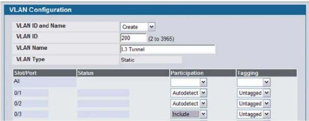
2 From the L3 Features > VLAN Routing Configuration page, create a VLAN routing interface on VLAN 200.
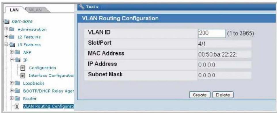
3 From the L3 Features > IP > Interface Configuration page, assign an IP address and subnet mask to the interface, and make sure routing is enabled.
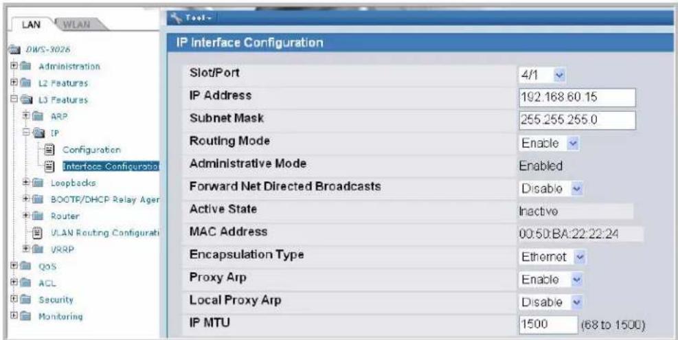
4 From the Monitoring > L3 Status > VLAN Routing Summary page, view the summary information for the VLAN routing interface.

CONFIGURING THE L3 TUNNEL NETWORK
Configure L3 tunneling by modifying or adding a Network. Then, make sure the network is associated with a VAP on the AP Profile assigned to the APs that wireless clients might use for roaming. Once you change the AP Profile, re-apply the profile to the APs to reset the APs that use the profile.

Note: When L3 tunneling is enabled, the VLAN ID for the network is not used. In fact, the switch puts the management VLAN ID, if any, on the tunneled packets.
In this example, the L3 Tunnel network is on Network 3 on the Default AP Profile. The SSID of the network is "L3 Tunnel," and the security mechanism is WPA Enterprise.
Example of Configuring L3 Roaming by Using the CLI
The following procedures show how to configure the D-Link Unified Switch by using the CLI. The Web interface configuration procedures follow this example.
1 Enter the network configuration mode for network 3.
(switch-prompt) #configure
(switch-prompt) (Config)#wireless
(switch-prompt) (Config-wireless)#network 3
2 Create the network name (SSID).
(switch-prompt) (Config-network)#ssid "L3 Tunnel"
3 Configure security on the network to control wireless client access.
For this network, the administrator uses WPA Enterprise for the security mode. The administrator must also configure the security on each client that is allowed to access the L3 Tunnel network.
(switch-prompt) (Config-network)#security mode wpa-enterprise
4 Enable L3 roaming.
(switch-prompt) (Config-network)#tunnel
5 Configure the L3 network IP address and subnet mask for the tunnel.

Note: The network address you enter must be the same subnet used by the VLAN routing interface created in "Creating the VLAN Routing Interface" on page 215.
(switch-prompt) (Config-network)#tunnel subnet 192.168.60.0 mask 255.255.255.0
6 Exit out of Network mode and Enter AP profile configuration mode for the default profile (Profile 1).
(switch-prompt) (Config-network)#exit
(switch-prompt) (Config-wireless)#ap profile 1
7 Enter the AP Profile Radio Config mode for the radio you want to use.
In this example, the L3 Tunnel network uses Radio 1, which is the 802.11g radio by default.
(switch-prompt) (Config-ap-profile)#radio 1
8 Enter the AP Profile VAP Config mode for VAP 2 and enable the VAP.
VAP 0 is the default network and is the only network enabled by default. In this example, the Guest networks is on VAP 0, the Corporate Network is on VAP 1, and the L3 Tunnel Network is on VAP 2.
(switch-prompt) (Config-ap-radio) #vap 2 (switch-prompt) (Config-ap-profile-vap) #enable
9 Associate the L3 Tunnel Network (network 3) with VAP 2.
(switch-prompt) (Config-ap-profile-vap) #network 3
10 Enter CTRL + Z to exit to Privileged EXEC mode and view the network configuration to make sure the L3 Tunnel Status is listed as "Configured" and to confirm that other network settings are correct.
(switch-prompt) #show wireless network 3
| Network ID...... | 3 |
| SSID...... | L3 Tunnel |
| Default VLAN...... | 1 |
| Hide SSID...... | Disable |
| Deny Broadcast...... | Disable |
| L3 Tunnel Mode...... | Enable |
| L3 Tunnel Status...... | Configured |
| L3 Tunnel Subnet IP...... | 192.168.60.0 |
| L3 Tunnel Subnet Mask...... | 255.255.255.0 |
| Security Mode...... | WPA Enterprise |
| MAC Authentication...... | Disable |
| RADIUS Use AP Profile...... | Enable |
| RADIUS Server IP...... | 0.0.0.0 |
| RADIUS Secret Configured...... | No |
| RADIUS Accounting...... | Disable |
| WPA Versions...... | WPA/WPA2 |
| WPA Ciphers...... | TKIP |
| WPA Key Type...... | ASCII |
| WPA Key...... | |
| WPA2 Pre-Authentication...... | Enable |
| WPA2 Pre-Authentication Limit (minutes)...... | 0 |
| WPA2 Pre-Authentication Timeout (minutes)...... | 0 |
| --More-- or (q)uit | |
| WPA2 Key Forwarding...... | Enable |
| WPA2 Key Caching Holdtime (minutes)...... | 10 |
| WEP Authentication Type...... | Open System |
| WEP Key Type...... | HEX |
| WEP Key Length (bits)...... | 128 |
| WEP Transfer Key Index...... | 1 |
| WEP Key 1...... | |
| WEP Key 2...... | |
| WEP Key 3...... | |
| WEP Key 4...... | |
An important value to note is the L3 Tunnel Status value. The following table lists the possible values and explains what they mean.
Table 92: L3 Tunnel Status Values
| L3 Tunnel Status Description | |
| None The status might be None for one of the following reasons:The WLAN Operational Status is disabledL3 Tunnel is DisabledThe network is not associated with any AP profiles. If you create or edit a network and configure L3 Tunneling, but there are no VAPs on any AP Profiles that use the network, the status is None. | |
| Configured | The L3 Tunnel is configured and ready to be applied to the APs that use this profile. |
| Not Configured - Routing Disabled | Routing is disabled on the routing interface. |
| Not Configured - No Routing Interface | The status might show this value for one of the following reasons:The routing interface for the L3 Tunnel network does not exist.IPv6 is enabled on the routing interface.IP Multicast is enabled on the routing interface.The Tunnel subnet address does not match a routing interface.In the example in this appendix, the VLAN routing interface has an IP address of 192.168.60.15/24, and the L3 Tunnel Subnet is 192.168.60.0/24, so the tunnel subnet matches a routing interface. |
11 From Privileged EXEC mode, apply the modified default profile to the APs that use the default profile (Profile 1). (switch-prompt) #wireless ap profile apply 1
After the managed AP updates complete, the L3 Tunnel network is available on all APs that use the default profile. Users who connect to an AP by using the L3 Tunnel SSID can roam among all APs without traffic interruption.
To test connectivity, make sure you can ping from each AP to the switch loopback IP address and the IP address used by the routing interface for L3 tunnels. From Privileged EXEC mode, you can enable debugging on the AP with the wireless ap debug
Once a wireless client associates with the tunneled subnet, use the ping command and set a large packet size to make sure you can send the desired MTU size through the tunnel.
From a Windows client, use -1
ping -l 1542 -f 192.168.60.15
From a Unix system, use -s
ping -s 1542 -M do 192.168.60.15
Example of Configuring L3 Roaming by Using the Web Interface
The following steps shows the procedures to configure the L3 Tunnel Network by using the Web interface on the switch.
1 From the Administration > Basic Setup > SSID tab, select the check box next to the SSID to configure and click Edit.
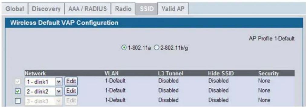
2 From Wireless Network Configuration page, configure the following settings:
- SSID—L3 Tunnel
- L3 Tunnel check box—Selected
- L3 Tunnel Subnet—192.168.60.0
- L3 Tunnel Mask—255.255.255.0.
- Security—WPA/WPA2
The L3 Tunnel Subnet is the network IP address of the VLAN routing interface configured in the procedures for "Creating the VLAN Routing Interface".
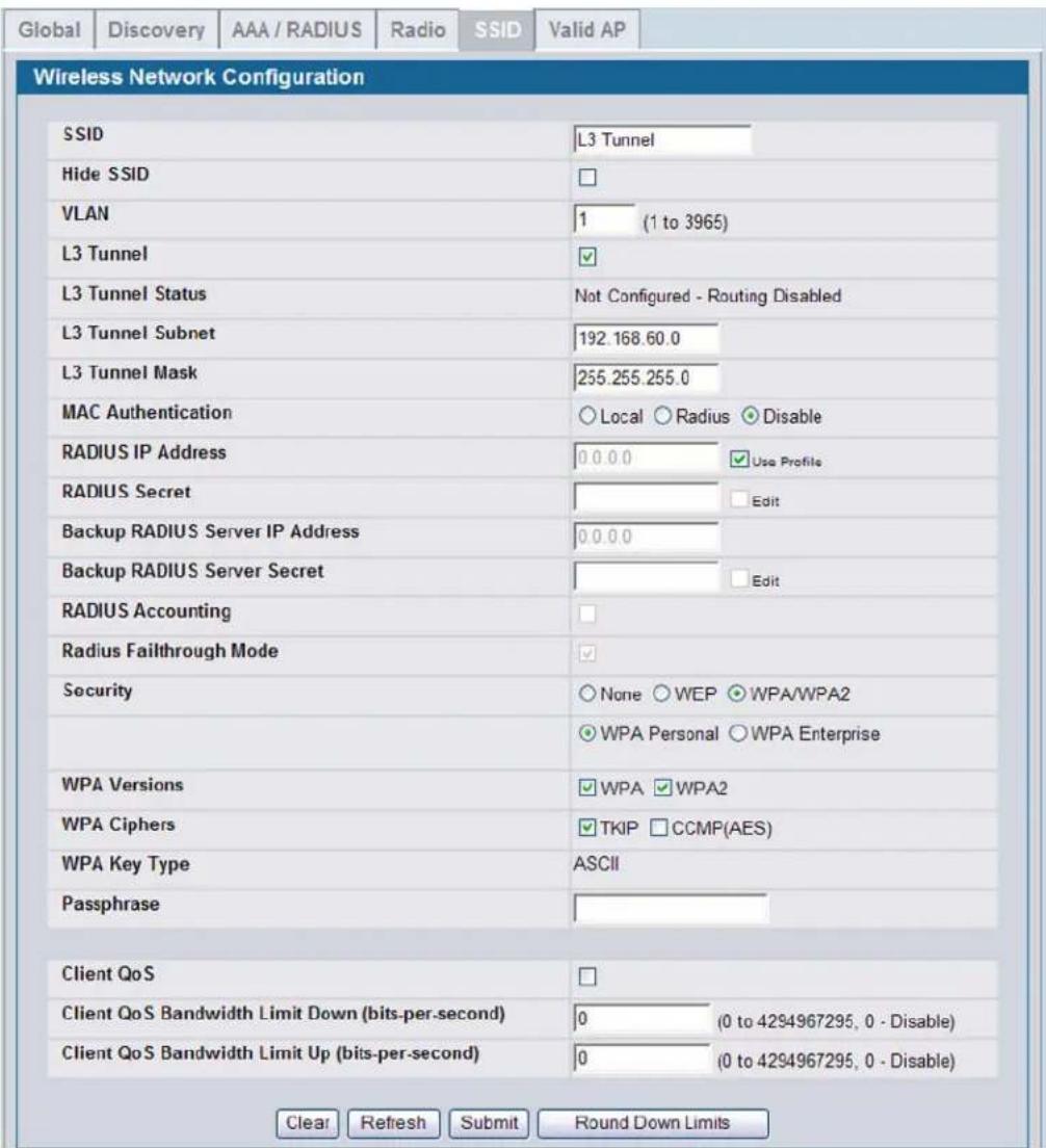
3 Click Submit to save the changes to the L3 Tunnel network configuration.
4 Check the L3 Tunnel Status to make sure the L3 Tunnel Status is Configured.
5 To apply the profile changes to the APs, click Administration > Advanced Configuration > AP Profiles.
6 Select the Default profile check box and click Apply.
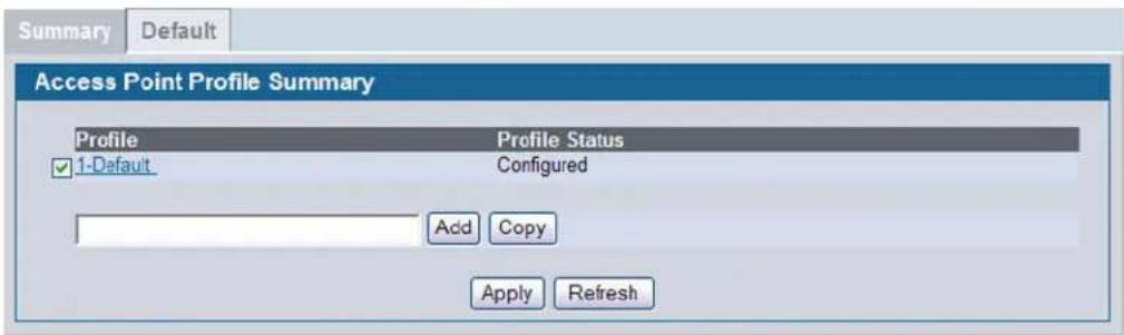
When you update the profile, the Unified Switch adds the L3 Tunnel network to the Managed APs that use the default profile.
CONFIGURING DHCP RELAY AND THE DHCP SERVER
Unless you use the Unified Switch as a DHCP server or use static IP addresses for all devices, you must enable DHCP relay on the switch so that the switch can forward DHCP requests from the roaming wireless clients to the DHCP server on your network.
If you choose to use the Unified Switch as a DHCP server for wireless clients, you must configure the DHCP server and the address pool for wireless clients.
Configuring the Relay Agent
Use the following command in Global Config mode to enable BootP and DHCP relay on the switch:
bootpdhcprelay enable
Use the following command in Global Config mode to specify the IP address of the BootP or DHCP server that will assign IP addresses to wireless clients:
bootpdhcprelay serverip 192.168.30.2
To configure BootP and DHCP relay from the Web interface on the switch, go to the L3 Features > BootP/DHCP Relay Agent > Configuration page. Configure the server IP address and enable the Admin Mode, then click Submit.
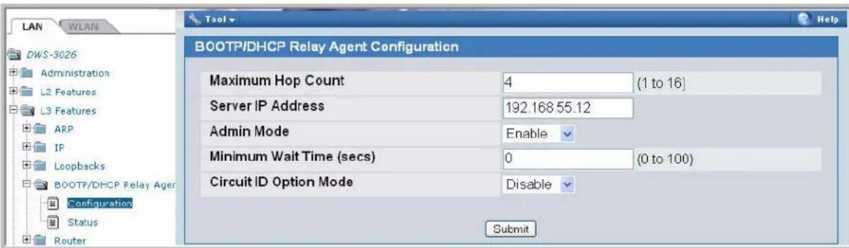
Configuring the DHCP Server
To configure DHCP on the D-Link Unified Switch, you configure the global DHCP settings and the address pool for the clients. The following example shows how to create an address pool for the wireless clients on the L3 Tunnel network. You can create additional address pools so that the DHCP server on the Unified Switch can serve IP addresses to wireless clients that use other networks (such as the Guest Network or Corporate LAN).
The following commands show how to configure a DHCP server to use for the wireless clients that connect to the L3 Tunnel wireless network.
1 From Global Config mode, enable DHCP.
(switch-prompt) (Config)#service dhcp
2 Exclude the IP addresses in the range of 192.168.60.1 through 192.168.60.50, which includes the IP addresses of WS1, WS2, and the Call Server.
(switch-prompt) (Config)#ip dhcp excluded-address 192.168.2.201 192.168.2.255
3 Create an address pool.
(switch-prompt) (Config)#ip dhcp pool vlan200
4 Configure the L3 Tunnel subnet and netmask as the network address for the clients on VLAN 200.
(switch-prompt) (Config)network 192.168.60.0 255.255.255.0
5 Configure the default router for the address pool.
(switch-prompt) (Config)default-router 192.168.60.1
Use the following procedures to perform the same configuration by using the Web interface.
1 From the Administration > DHCP Server > Global Configuration page, enable the Admin Mode and enter the range of IP addresses that you do not want to assign to wireless clients, then click Submit.
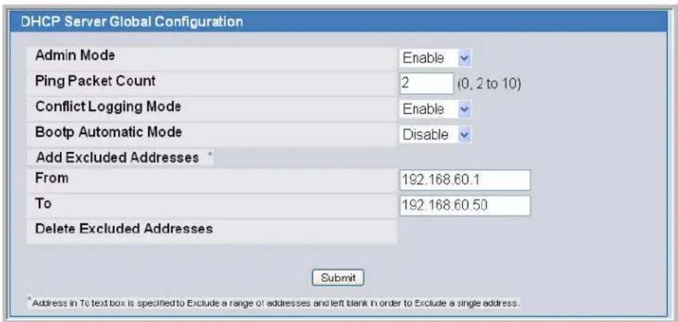
2 Navigate to the Administration > DHCP Server > Pool Configuration page and select Create from the Pool Name menu.
3 Enter a name for the address pool in the Pool Name field and select Dynamic from the Type of Binding menu.
4 Enter a network number, network mask, and default router address in the appropriate fields and click Submit.
Manual
Access the guide for the D-Link DWS-3026 here, completely free. This manual falls under the not categorized category and has been rated by 2 users with an average score of 7.3. The manual is presently available in the following languages: English. If you have any specific questions about the D-Link DWS-3026 or need further assistance with your product, feel free to ask.
Ask your question here

natural_image
Illustration of two people in speech bubbles with a question mark above their head (no text or symbols present)Need help?
Do you have a particular question about the D-Link DWS-3026 not answered by the manual?
Type your question here ...
Ask a question
√ Receive updates on solutions
√ Get answers to your question
Question and answer
Number of questions: 0
Appendix D: Understanding Quality of Service
Quality of Service (QoS) provides you with the ability to specify parameters on multiple queues for increased throughput and better performance of differentiated wireless traffic like Voice-over-IP (VoIP), other types of audio, video, and streaming media as well as traditional IP data over the D-Link Unified Access System.
A primary factor that affects QoS is network congestion due to an increased number of clients attempting to access the air waves and higher traffic volume competing for bandwidth during a busy time of day. The most noticeable degradation in service on a busy, overloaded network will be evident in time-sensitive applications like Video, Voice-over-IP (VoIP), and streaming media.
Unlike typical data files which are less affected by variability in QoS, Video, VoIP and streaming media must be sent in a specific order at a consistent rate and with minimum delay between Packet transmission. If the quality of service is compromised, the audio or video will be distorted.
QoS AND LOAD BALANCING
By using a combination of load balancing and QoS techniques, you can provide a high quality of service for time-sensitive applications even on a busy network. Load balancing sets thresholds for client associations and AP utilization. QoS is a means of allocating bandwidth and network access based on transmission priorities for different types of wireless traffic within a single access point.
802.11E AND WMM STANDARDS SUPPORT
QoS describes a range of technologies for controlling data streams on shared network connections. The IEEE 802.11e task group is in the process of defining a QoS standard for transmission quality and availability of service on wireless networks. QoS is designed to provide better network service by minimizing network congestion; limiting jitter, latency, and packet loss; supporting dedicated bandwidth for time-sensitive or mission critical applications, and prioritizing wireless traffic for channel access.
As with all IEEE 802.11 working group standards, the goal is to provide a standard way of implementing QoS features so that components from different companies are interoperable.
The D-Link Access Points provide QoS based on the Wireless Multimedia (WMM) specification, which implements a subset of 802.11e features.

Note: For the IEEE 802.11e, only Unscheduled Automatic Power Save Delivery (U-APSD), part of the 802.11e, is supported when DWL-8600APs are managed by a DWS-3000 switch.
Both access points and wireless clients (laptops, consumer electronics products) can be WMM-enabled by the Wi-Fi Alliance.
COORDINATING TRAFFIC FLOW
Configuring QoS options on the D-Link Unified Access System consists of setting parameters on existing queues for different types of wireless traffic. You can configure different minimum and maximum wait times for the transmission of packets in
each queue based on the requirements of the media being sent. Queues automatically provide minimum transmission delay for Voice, Video, multimedia, and mission critical applications, and rely on best-effort parameters for traditional IP data.
For example, time-sensitive Voice, Video, and multimedia are given effectively higher priority for transmission (lower wait times for channel access), while other applications and traditional IP data which are less time-sensitive but often more data-intensive are expected to tolerate longer wait times.
The D-Link Unified Access System implements QoS based on the IEEE Wireless Multimedia (WMM) standard. A Linux-based queuing class is used to tag packets and establish multiple queues. The queues provided offer built-in prioritization and routing based on the type of data being transmitted.
The Administration UI provides a way for you to configure parameters on the queues.
QoS QUEUES AND DSCP ON PACKETS
QoS on the D-Link Unified Access System leverages WMM information in the IP packet header related to Diff-Serv Code Point (DSCP). Every IP packet sent over the network includes a DSCP field in the header that indicates how the data should be prioritized and transmitted over the network. The DSCP field consists of a 6 bit value defined by the local administration. For WMM, Wi-Fi Alliance suggests a particular mapping for DSCP values
The access point examines the DSCP field in the headers of all packets that pass through the AP. Based on the value in a packet's DSCP field, the AP prioritizes the packet for transmission by assigning it to one of the queues. This process occurs automatically, regardless of whether you deliberately configure QoS or not.
A different type of data is associated with each queue. The queue and associated priorities and parameters for transmission are as follows:
- Data 0 (Voice). Highest priority queue, minimum delay. Time-sensitive data such as Voice over IP (VoIP) is automatically sent to this queue.
- Data 1 (Video). High priority queue, minimum delay. Time-sensitive data such as Video and other streaming media are automatically sent to this queue.
• Data 2 (Best Effort). Medium priority queue, medium throughput and delay. Most traditional IP data is sent to this queue. - Data 3 (Background). Lowest priority queue, high throughput. Bulk data that requires maximum throughput and is not time-sensitive is sent to this queue (FTP data, for example).
Using the QoS settings in the AP profile, you can configure Enhanced Distributed Channel Access (EDCA) parameters that determine how each queue is treated when it is sent by the access point to the client or by the client to the access point.
Wireless traffic travels:
- Downstream from the access point to the client station
- Upstream from client station to access point
- Upstream from access point to network
- Downstream from network to access point
With WMM enabled, QoS settings on the D-Link Unified Access System affect the first two of these; downstream traffic flowing from the access point to client station (AP EDCA parameters) and the upstream traffic flowing from the station to the access point (station EDCA parameters).
With WMM disabled, you can still set some parameters on the downstream traffic flowing from the access point to the client station (AP EDCA parameters).
The other phases of the traffic flow (to and from the network) are not under control of the QoS settings on the AP.
EDCF CONTROL OF DATA FRAMES AND AIFS
Data is transmitted over 802.11 wireless networks in frames. A frame consists of a discrete portion of data along with some descriptive meta-information packaged for transmission on a wireless network.
Each frame includes a source and destination MAC address, a control field with protocol version, frame type, frame sequence number, frame body (with the actual information to be transmitted) and frame check sequence for error detection.
The 802.11 standard defines various frame types for management and control of the wireless infrastructure, and for data transmission. 802.11 frame types are (1) management frames, (2) control frames, and (3) data frames. Management and control frames (which manage and control the availability of the wireless infrastructure) automatically have higher priority for transmission.
802.11e uses interframe spaces to regulate which frames get access to available channels and to coordinate wait times for transmission of different types of data.
Management and control frames wait a minimum amount of time for transmission; they wait a short interframe space (SIF). These wait times are built-in to 802.11 as infrastructure support and are not configurable.
The D-Link Unified Access System supports the Enhanced Distribution Coordination Function (EDCF) as defined by the 802.11e standard. EDCF, which is an enhancement to the DCF standard and is based on CSMA/CA protocol, defines the interframe space (IFS) between data frames. Data frames wait for an amount of time defined as the arbitration interframe space (AIFS) before transmitting.
This parameter is configurable.
RANDOM BACKOFF AND CONTENTION WINDOWS
If an access point detects that the medium is in use (busy), it uses the DCF random backoff timer to determine the amount of time to wait before attempting to access a given channel again. Each access point waits some random period of time between retries. The wait time (initially a random value within a range specified as the Minimum Contention Window) increases exponentially up to a specified limit (Maximum Contention Window). The random delay avoids most of the collisions that would occur if multiple APs got access to the medium at the same time and tried to transmit data simultaneously. The more active users you have on a network, the more significant the performance gains of the backoff timer will be in reducing the number of collisions and retransmissions.
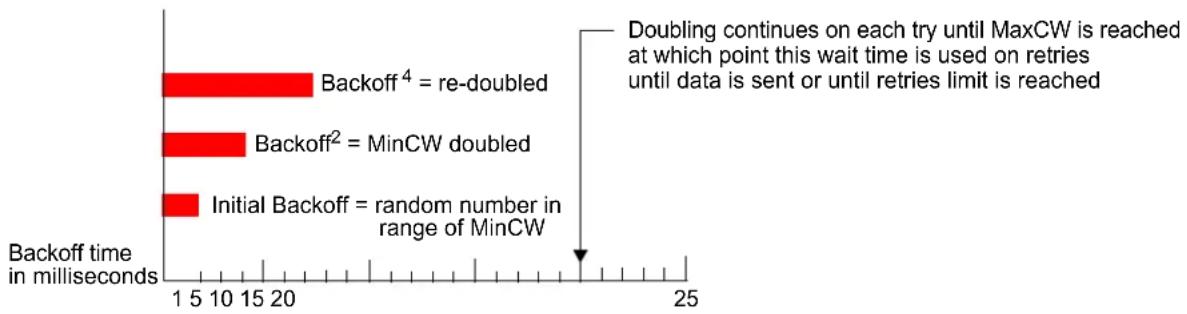
bar
| Method | Backoff time (milliseconds) | | :--- | :--- | | Backoff⁴ = re-doubled | 21 | | Backoff² = MinCW doubled | 14 | | Initial Backoff = random number in range of MinCW | 15 |The random backoff used by the access point is a configurable parameter. To describe the random delay, a "Minimum Contention Window" (MinCW) and a "Maximum Contention Window" (MaxCW) is defined.
- The value specified for the Minimum Contention Window is the upper limit of a range for the initial random backoff wait time. The number used in the random backoff is initially a random number between 0 and the number defined for the Minimum Contention Window.
- If the first random backoff time ends before successful transmission of the data frame, the access point increments a retry counter, and doubles the value of the random backoff window. The value specified in the Maximum Contention Window is the upper limit for this doubling of the random backoff. This doubling continues until either the data frame is sent or the Maximum Contention Window size is reached.
PACKET BURSTING FOR BETTER PERFORMANCE
The D-Link Unified Access System includes 802.11e based packet bursting technology that increases data throughput and speed of transmission over the wireless network. Packet bursting enables the transmission of multiple packets without the extra overhead of header information. The effect of this is to increase network speed and data throughput. The size of packet bursts allowed (maximum burst length) is a configurable parameter.
TXOP INTERVAL FOR CLIENT STATIONS
The Transmission Opportunity (TXOP) is an interval of time when a Wi-Fi Multimedia (WMM) client station has the right to initiate transmissions onto the wireless medium (WM).
802.1P AND DSCP TAGS
IEEE 802.1p is an extension of the IEEE 802 standard and is responsible for QoS provision. One purpose of 802.1p is to prioritize network traffic at the data link/ MAC layer.
The 802.1q tag includes a three-bit field for prioritization, which allows packets to be grouped into various traffic classes. Eight priority levels are defined. The highest priority is seven, which might go to network critical traffic (voice). The lowest priority level is zero, this is used as a best-effort default, it is invoked automatically when no other value has been set.

Note: IEEE 802.1 prioritization will not work unless QoS and WMM are enabled. WMM must be enabled on both the AP and on the client connecting to the AP.
Figure 110 outlines the way in which tags are retrieved and traffic prioritized on a network.
Figure 110: Traffic Prioritization
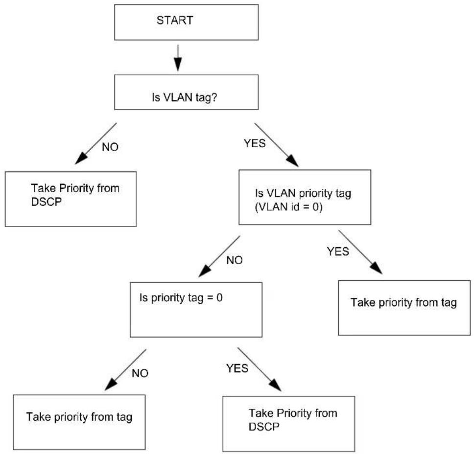
flowchart
graph TD
    A["START"] --> B["Is VLAN tag?"]
    B -->|NO| C["Take Priority from DSCP"]
    B -->|YES| D["Is VLAN priority tag (VLAN id = 0)"]
    C -->|NO| E["Is priority tag = 0"]
    D -->|YES| F["Take priority from tag"]
    E -->|NO| G["Take priority from tag"]
    E -->|YES| H["Take Priority from DSCP"]
Table 93 outlines the VLAN priority and DSCP values.
Table 93: VLAN Priority Tags
| VLAN Priority Priority DSCP Value | |||
| 0 | B | e0 | $ |
| 1 Background 16 | |||
| 2 Background | 8 | ||
| 3 Best Effort 24 | |||
| 4 Video 32 | |||
| 5 Video 40 | |||
| 6 Voice 48 | |||
| 7 Voice 56 | |||
Appendix E: Limited Warranty (USA Only)
Subject to the terms and conditions set forth herein, D-Link Systems, Inc. ("D-Link") provides this Limited Warranty:
• Only to the person or entity that originally purchased the product from D-Link or its authorized reseller or distributor, and
- Only for products purchased and delivered within the fifty states of the United States, the District of Columbia, U.S. Possessions or Protectorates, U.S. Military Installations, or addresses with an APO or FPO.
Limited Warranty: D-Link warrants that the hardware portion of the D-Link product described below (“Hardware”) will be free from material defects in workmanship and materials under normal use from the date of original retail purchase of the product, for the period set forth below (“Warranty Period”), except as otherwise stated herein.
Limited Lifetime Warranty for the product is defined as follows:
- Hardware: For as long as the original customer/end user owns the product, or five (5) years after product discontinuance, whichever occurs first (excluding power supplies and fans)
• Power supplies and fans: Three (3) Year - Spare parts and spare kits: Ninety (90) days
The customer's sole and exclusive remedy and the entire liability of D-Link and its suppliers under this Limited Warranty will be, at D-Link's option, to repair or replace the defective Hardware during the Warranty Period at no charge to the original owner or to refund the actual purchase price paid. Any repair or replacement will be rendered by D-Link at an Authorized D-Link Service Office. The replacement hardware need not be new or have an identical make, model or part. D-Link may, at its option, replace the defective Hardware or any part thereof with any reconditioned product that D-Link reasonably determines is substantially equivalent (or superior) in all material respects to the defective Hardware. Repaired or replacement hardware will be warranted for the remainder of the original Warranty Period or ninety (90) days, whichever is longer, and is subject to the same limitations and exclusions. If a material defect is incapable of correction, or if D-Link determines that it is not practical to repair or replace the defective Hardware, the actual price paid by the original purchaser for the defective Hardware will be refunded by D-Link upon return to D-Link of the defective Hardware. All Hardware or part thereof that is replaced by D-Link, or for which the purchase price is refunded, shall become the property of D-Link upon replacement or refund.
Limited Software Warranty: D-Link warrants that the software portion of the product ("Software") will substantially conform to D-Link's then current functional specifications for the Software, as set forth in the applicable documentation, from the date of original retail purchase of the Software for a period of ninety (90) days ("Software Warranty Period"), provided that the Software is properly installed on approved hardware and operated as contemplated in its documentation. D-Link further warrants that, during the Software Warranty Period, the magnetic media on which D-Link delivers the Software will be free of physical defects. The customer's sole and exclusive remedy and the entire liability of D-Link and its suppliers under this Limited Warranty will be, at D-Link's option, to replace the non-conforming Software (or defective media) with software that substantially conforms to D-Link's functional specifications for the Software or to refund the portion of the actual purchase price paid that is attributable to the Software. Except as otherwise agreed by D-Link in writing, the replacement Software is provided only to the original licensee, and is subject to the terms and conditions of the license granted by D-Link for the Software. Replacement Software will be warranted for the remainder of the original Warranty Period and is subject to the same limitations and exclusions. If a material non-conformance is incapable of correction, or if D-Link determines in its sole discretion that it is not practical to replace the non-conforming Software, the price paid by the original licensee for the non-conforming Software will be refunded by D-Link; provided that the non-conforming Software (and all copies thereof) is first returned to D-Link. The license granted respecting any Software for which a refund is given automatically terminates.
Non-Applicability of Warranty: The Limited Warranty provided hereunder for Hardware and Software portions of D-Link's products will not be applied to and does not cover any refurbished product and any product purchased through the inventory clearance or liquidation sale or other sales in which D-Link, the sellers, or the liquidators expressly disclaim their warranty
obligation pertaining to the product and in that case, the product is being sold “As-Is” without any warranty whatsoever including, without limitation, the Limited Warranty as described herein, notwithstanding anything stated herein to the contrary.
Submitting A Claim: The customer shall return the product to the original purchase point based on its return policy. In case the return policy period has expired and the product is within warranty, the customer shall submit a claim to D-Link as outlined below:
- The customer must submit with the product as part of the claim a written description of the Hardware defect or Software nonconformance in sufficient detail to allow D-Link to confirm the same, along with proof of purchase of the product (such as a copy of the dated purchase invoice for the product) if the product is not registered.
- The customer must obtain a Case ID Number from D-Link Technical Support at 1-877-453-5465, who will attempt to assist the customer in resolving any suspected defects with the product. If the product is considered defective, the customer must obtain a Return Material Authorization ("RMA") number by completing the RMA form and entering the assigned Case ID Number at https://rma.dlink.com/.
- After an RMA number is issued, the defective product must be packaged securely in the original or other suitable shipping package to ensure that it will not be damaged in transit, and the RMA number must be prominently marked on the outside of the package. Do not include any manuals or accessories in the shipping package. D-Link will only replace the defective portion of the product and will not ship back any accessories.
- The customer is responsible for all in-bound shipping charges to D-Link. No Cash on Delivery ("COD") is allowed. Products sent COD will either be rejected by D-Link or become the property of D-Link. Products shall be fully insured by the customer and shipped to D-Link Systems, Inc., 17595 Mt. Herrmann, Fountain Valley, CA 92708. D-Link will not be held responsible for any packages that are lost in transit to D-Link. The repaired or replaced packages will be shipped to the customer via UPS Ground or any common carrier selected by D-Link. Return shipping charges shall be prepaid by D-Link if you use an address in the United States, otherwise we will ship the product to you freight collect. Expedited shipping is available upon request and provided shipping charges are prepaid by the customer.
D-Link may reject or return any product that is not packaged and shipped in strict compliance with the foregoing requirements, or for which an RMA number is not visible from the outside of the package. The product owner agrees to pay D-Link's reasonable handling and return shipping charges for any product that is not packaged and shipped in accordance with the foregoing requirements, or that is determined by D-Link not to be defective or non-conforming.
What Is Not Covered: The Limited Warranty provided herein by D-Link does not cover: Products that, in D-Link's judgment, have been subjected to abuse, accident, alteration, modification, tampering, negligence, misuse, faulty installation, lack of reasonable care, repair or service in any way that is not contemplated in the documentation for the product, or if the model or serial number has been altered, tampered with, defaced or removed; Initial installation, installation and removal of the product for repair, and shipping costs; Operational adjustments covered in the operating manual for the product, and normal maintenance; Damage that occurs in shipment, due to act of God, failures due to power surge, and cosmetic damage; Any hardware, software, firmware or other products or services provided by anyone other than D-Link; and Products that have been purchased from inventory clearance or liquidation sales or other sales in which D-Link, the sellers, or the liquidators expressly disclaim their warranty obligation pertaining to the product. While necessary maintenance or repairs on your Product can be performed by any company, we recommend that you use only an Authorized D-Link Service Office. Improper or incorrectly performed maintenance or repair voids this Limited Warranty.
Disclaimer of Other Warranties: EXCEPT FOR THE LIMITED WARRANTY SPECIFIED HEREIN, THE PRODUCT IS PROVIDED "AS-IS" WITHOUT ANY WARRANTY OF ANY KIND WHATSOEVER INCLUDING, WITHOUT LIMITATION, ANY WARRANTY OF MERCHANTABILITY, FITNESS FOR A PARTICULAR PURPOSE AND NON-INFRINGEMENT. IF ANY IMPLIED WARRANTY CANNOT BE DISCLAIMED IN ANY TERRITORY WHERE A PRODUCT IS SOLD, THE DURATION OF SUCH IMPLIED WARRANTY SHALL BE LIMITED TO NINETY (90) DAYS. EXCEPT AS EXPRESSLY COVERED UNDER THE LIMITED WARRANTY PROVIDED HEREIN, THE ENTIRE RISK AS TO THE QUALITY, SELECTION AND PERFORMANCE OF THE PRODUCT IS WITH THE PURCHASER OF THE PRODUCT.
Limitation of Liability: TO THE MAXIMUM EXTENT PERMITTED BY LAW, D-LINK IS NOT LIABLE UNDER ANY CONTRACT, NEGLIGENCE, STRICT LIABILITY OR OTHER LEGAL OR EQUITABLE THEORY FOR ANY LOSS OF USE OF THE PRODUCT, INCONVENIENCE OR DAMAGES OF ANY CHARACTER, WHETHER DIRECT, SPECIAL, INCIDENTAL OR CONSEQUENTIAL (INCLUDING, BUT NOT LIMITED TO, DAMAGES FOR LOSS OF GOODWILL, LOSS OF REVENUE OR PROFIT, WORK STOPPAGE, COMPUTER FAILURE OR MALFUNCTION, FAILURE OF OTHER EQUIPMENT OR COMPUTER PROGRAMS TO WHICH D-LINK'S PRODUCT IS CONNECTED WITH, LOSS OF INFORMATION OR DATA CONTAINED IN, STORED ON, OR INTEGRATED WITH ANY PRODUCT RETURNED TO D-LINK FOR WARRANTY SERVICE) RESULTING FROM THE USE OF THE PRODUCT, RELATING TO WARRANTY SERVICE, OR ARISING OUT OF ANY BREACH OF THIS LIMITED WARRANTY, EVEN IF D-LINK HAS BEEN ADVISED OF THE POSSIBILITY OF SUCH DAMAGES. THE SOLE REMEDY FOR A BREACH OF THE FOREGOING LIMITED WARRANTY IS REPAIR, REPLACEMENT OR REFUND OF THE DEFECTIVE OR NON-CONFORMING PRODUCT. THE MAXIMUM LIABILITY OF D-LINK UNDER THIS WARRANTY IS LIMITED TO THE PURCHASE PRICE OF THE PRODUCT COVERED BY THE WARRANTY. THE FOREGOING EXPRESS WRITTEN WARRANTIES AND REMEDIES ARE EXCLUSIVE AND ARE IN LIEU OF ANY OTHER WARRANTIES OR REMEDIES, EXPRESS, IMPLIED OR STATUTORY.
Governing Law: This Limited Warranty shall be governed by the laws of the State of California. Some states do not allow exclusion or limitation of incidental or consequential damages, or limitations on how long an implied warranty lasts, so the foregoing limitations and exclusions may not apply. This Limited Warranty provides specific legal rights and you may also have other rights which vary from state to state.
Trademarks: D-Link is a registered trademark of D-Link Systems, Inc. Other trademarks or registered trademarks are the property of their respective owners.
Copyright Statement: No part of this publication or documentation accompanying this product may be reproduced in any form or by any means or used to make any derivative such as translation, transformation, or adaptation without permission from D-Link Corporation/D-Link Systems, Inc., as stipulated by the United States Copyright Act of 1976 and any amendments thereto. Contents are subject to change without prior notice. Copyright 2007 by D-Link Corporation/D-Link Systems, Inc. All rights reserved.
CE Mark Warning: This is a Class A product. In a residential environment, this product may cause radio interference, in which case the user may be required to take adequate measures.
FCC Statement: This equipment has been tested and found to comply with the limits for a Class A digital device, pursuant to part 15 of the FCC Rules. These limits are designed to provide reasonable protection against harmful interference in a commercial installation. This equipment generates, uses, and can radiate radio frequency energy and, if not installed and used in accordance with the instructions, may cause harmful interference to radio communication. However, there is no guarantee that interference will not occur in a particular installation. Operation of this equipment in a residential environment is likely to cause harmful interference to radio or television reception. If this equipment does cause harmful interference to radio or television reception, which can be determined by turning the equipment off and on, the user is encouraged to try to correct the interference by one or more of the following measures:
- Reorient or relocate the receiving antenna.
- Increase the separation between the equipment and receiver.
- Connect the equipment into an outlet on a circuit different from that to which the receiver is connected.
- Consult the dealer or an experienced radio/TV technician for help.
For detailed warranty information applicable to products purchased outside the United States, please contact the corresponding local D-Link office.
PRODUCT REGISTRATION
Register your D-Link product online at http://support.dlink.com/register.
Product registration is entirely voluntary and failure to complete or return this form will not diminish your warranty rights.
LIMITED WARRANTY
D-Link provides this limited warranty for its product only to the person or entity who originally purchased the product from D-Link or its authorized reseller or distributor. D-Link would fulfill the warranty obligation according to the local warranty policy in which you purchased our products.
Limited Hardware Warranty: D-Link warrants that the hardware portion of the D-Link products described below ("Hardware") will be free from material defects in workmanship and materials from the date of original retail purchase of the Hardware, for the period set forth below applicable to the product type ("Warranty Period") if the Hardware is used and serviced in accordance with applicable documentation; provided that a completed Registration Card is returned to an Authorized D-Link Service Office within ninety (90) days after the date of original retail purchase of the Hardware. If a completed Registration Card is not received by an authorized D-Link Service Office within such ninety (90) period, then the Warranty Period shall be ninety (90) days from the date of purchase.
Product Type Warranty Period
| Product (including Power Supplies and Fans) One (1) Year |
| Spare parts and pare kits Ninety (90) days |
D-Link's sole obligation shall be to repair or replace the defective Hardware at no charge to the original owner. Such repair or replacement will be rendered by D-Link at an Authorized D-Link Service Office. The replacement Hardware need not be new or of an identical make, model or part; D-Link may in its discretion may replace the defective Hardware (or any part thereof) with any reconditioned product that D-Link reasonably determines is substantially equivalent (or superior) in all material respects to the defective Hardware. The Warranty Period shall extend for an additional ninety (90) days after any repaired or replaced Hardware is delivered. If a material defect is incapable of correction, or if D-Link determines in its sole discretion that it is not practical to repair or replace the defective Hardware, the price paid by the original purchaser for the defective Hardware will be refunded by D-Link upon return to D-Link of the defective Hardware. All Hardware (or part thereof) that is replaced by D-Link, or for which the purchase price is refunded, shall become the property of D-Link upon replacement or refund.
Limited Software Warranty: D-Link warrants that the software portion of the product ("Software") will substantially conform to D-Link's then current functional specifications for the Software, as set forth in the applicable documentation, from the date of original delivery of the Software for a period of ninety (90) days ("Warranty Period"), if the Software is properly installed on approved hardware and operated as contemplated in its documentation. D-Link further warrants that, during the Warranty Period, the magnetic media on which D-Link delivers the Software will be free of physical defects. D-Link's sole obligation shall be to replace the non-conforming Software (or defective media) with software that substantially conforms to D-Link's functional specifications for the Software. Except as otherwise agreed by D-Link in writing, the replacement Software is provided only to the original licensee, and is subject to the terms and conditions of the license granted by D-Link for the Software. The Warranty Period shall extend for an additional ninety (90) days after any replacement Software is delivered. If a material non-conformance is incapable of correction, or if D-Link determines in its sole discretion that it is not practical to replace the non-conforming Software, the price paid by the original licensee for the non-conforming Software will be refunded by D-Link; provided that the non-conforming Software (and all copies thereof) is first returned to D-Link. The license granted respecting any Software for which a refund is given automatically terminates.
What You Must Do For Warranty Service:
Registration Card. The Registration Card provided at the back of this manual must be completed and returned to an Authorized D-Link Service Office for each D-Link product within ninety (90) days after the product is purchased and/or licensed. The addresses/telephone/fax list of the nearest Authorized D-Link Service Office is provided in the back of this manual. FAILURE TO PROPERLY COMPLETE AND TIMELY RETURN THE REGISTRATION CARD MAY AFFECT THE WARRANTY FOR THIS PRODUCT.
Submitting A Claim. Any claim under this limited warranty must be submitted in writing before the end of the Warranty Period to an Authorized D-Link Service Office. The claim must include a written description of the Hardware defect or Software nonconformance in sufficient detail to allow D-Link to confirm the same. The original product owner must obtain a Return Material Authorization (RMA) number from the Authorized D-Link Service Office and, if requested, provide written proof of purchase of the product (such as a copy of the dated purchase invoice for the product) before the warranty service is provided. After an RMA number is issued, the defective product must be packaged securely in the original or other suitable shipping package to ensure that it will not be damaged in transit, and the RMA number must be prominently marked on the outside of the package. The packaged product shall be insured and shipped to Authorized D-Link Service Office with all shipping costs prepaid. D-Link may reject or return any product that is not packaged and shipped in strict compliance with the foregoing requirements, or for which an RMA number is not visible from the outside of the package. The product owner agrees to pay D-Link's reasonable handling and return shipping charges for any product that is not packaged and shipped in accordance with the foregoing requirements, or that is determined by D-Link not to be defective or non-conforming.
What Is Not Covered
This limited warranty provided by D-Link does not cover:
- Products that have been subjected to abuse, accident, alteration, modification, tampering, negligence, misuse, faulty installation, lack of reasonable care, repair or service in any way that is not contemplated in the documentation for the product, or if the model or serial number has been altered, tampered with, defaced or removed;
- Initial installation, installation and removal of the product for repair, and shipping costs;
• Operational adjustments covered in the operating manual for the product, and normal maintenance;
• Damage that occurs in shipment, due to act of God, failures due to power surge, and cosmetic damage;
• Any hardware, software, firmware or other products or services provided by anyone other than D-Link.
Disclaimer of Other Warranties: EXCEPT FOR THE LIMITED WARRANTY SPECIFIED HEREIN, THE PRODUCT IS PROVIDED "AS-IS" WITHOUT ANY WARRANTY OF ANY KIND INCLUDING, WITHOUT LIMITATION, ANY WARRANTY OF MERCHANTABILITY, FITNESS FOR A PARTICULAR PURPOSE AND NON-INFRINGEMENT. IF ANY IMPLIED WARRANTY CANNOT BE DISCLAIMED IN ANY TERRITORY WHERE A PRODUCT IS SOLD, THE DURATION OF SUCH IMPLIED WARRANTY SHALL BE LIMITED TO NINETY (90) DAYS. EXCEPT AS EXPRESSLY COVERED UNDER THE LIMITED WARRANTY PROVIDED HEREIN, THE ENTIRE RISK AS TO THE QUALITY, SELECTION AND PERFORMANCE OF THE PRODUCT IS WITH THE PURCHASER OF THE PRODUCT.
Limitation of Liability: TO THE MAXIMUM EXTENT PERMITTED BY LAW, D-LINK IS NOT LIABLE UNDER ANY CONTRACT, NEGLIGENCE, STRICT LIABILITY OR OTHER LEGAL OR EQUITABLE THEORY FOR ANY LOSS OF USE OF THE PRODUCT, INCONVENIENCE OR DAMAGES OF ANY CHARACTER, WHETHER DIRECT, SPECIAL, INCIDENTAL OR CONSEQUENTIAL (INCLUDING, BUT NOT LIMITED TO, DAMAGES FOR LOSS OF GOODWILL, WORK STOPPAGE, COMPUTER FAILURE OR MALFUNCTION, LOSS OF INFORMATION OR DATA CONTAINED IN, STORED ON, OR INTEGRATED WITH ANY PRODUCT RETURNED TO D-LINK FOR WARRANTY SERVICE) RESULTING FROM THE USE OF THE PRODUCT, RELATING TO WARRANTY SERVICE, OR ARISING OUT OF ANY BREACH OF THIS LIMITED WARRANTY, EVEN IF D-LINK HAS BEEN ADVISED OF THE POSSIBILITY OF SUCH DAMAGES. THE SOLE REMEDY FOR A BREACH OF THE FOREGOING LIMITED WARRANTY IS REPAIR, REPLACEMENT OR REFUND OF THE DEFECTIVE OR NON-CONFORMING PRODUCT.
GOVERNING LAW: This Limited Warranty shall be governed by the laws of the state of California.
Some states do not allow exclusion or limitation of incidental or consequential damages, or limitations on how long an implied warranty lasts, so the foregoing limitations and exclusions may not apply. This limited warranty provides specific legal rights and the product owner may also have other rights which vary from state to state.
Trademarks
© 2001-2010 D-Link Corporation. All Rights Reserved. Contents subject to change without prior notice. D-Link is a registered trademark of D-Link Corporation/D-Link Systems, Inc. All other trademarks belong to their respective proprietors.
Copyright Statement
No part of this publication may be reproduced in any form or by any means or used to make any derivative such as translation, transformation, or adaptation without permission from D-Link Corporation/D-Link Systems Inc., as stipulated by the United States Copyright Act of 1976.
FCC Warning
This equipment has been tested and found to comply with the limits for a Class A digital device, pursuant to Part 15 of the FCC Rules. These limits are designed to provide reasonable protection against harmful interference when the equipment is operated in a commercial environment. This equipment generates, uses, and can radiate radio frequency energy and, if not installed and used in accordance with this manual, may cause harmful interference to radio communications. Operation of this equipment in a residential area is likely to cause harmful interference in which case the user will be required to correct the interference at his own expense.
Appendix F: Technical Support
Technical Support
D-Link's website contains the latest user documentation and software updates for D-Link products.
U.S. and Canadian customers can contact D-Link Technical Support through our website or by phone.
United States
Telephone
(877) 354-6555
World Wide Web
http://support.dlink.com
Canada
Telephone
(877) 354-6560
World Wide Web
http://support.dlink.com
D-Link®
© 2001-2010 D-Link Corporation. All Rights Reserved. D-Link, the D-Link logo, and AirPremier are trademarks or registered trademarks of D-Link Corporation or its subsidiaries in the United States and other countries. Other trademarks are the property of their respective owners. All references to speed are for comparison purposes only. Product specifications, size, and shape are subject to change without notice, and actual product appearance may differ from that depicted herein. Visit www.dlink.com for more details.
Technical Support
You can find software updates and user documentation on the D-Link websites.
If you require product support, we encourage you to browse our FAQ section on the website before contacting the support line. We have many FAQ's that we hope will provide you a speedy resolution for your problem.
For Customers within the United Kingdom & Ireland:
D-Link UK & Ireland Technical Support over the Internet:
http://www.dlink.co.uk
ftp://ftp.dlink.co.uk
D-Link UK & Ireland Technical Support over the Telephone:
08456 12 0003 (United Kingdom)
+1890 886 899 (Ireland)
Lines Open
8.00am-10.00pm Mon-Fri
10.00am-7.00pm Sat & Sun
D-Link®
Building Networks for People
Building Networks for People
Assistance technique
e-mail : support@dlink.ca
D-Link®
Building Networks for People
Asistencia Técnica
Building Networks for People
Supporto tecnico
Building Networks for People
Technical Support
You can find software updates and user documentation on the D-Link website.
D-Link provides free technical support for customers within Benelux for the duration of the warranty period on this product.
Benelux customers can contact D-Link technical support through our website, or by phone.
Tech Support for customers within the Netherlands:
D-Link Technical Support over the Telephone:
0900 501 2007
Monday to Friday 9:00 am to 10:00 pm
D-Link Technical Support over the Internet:
www.dlink.nl
Tech Support for customers within Belgium:
D-Link Technical Support over the Telephone:
070 66 06 40
Monday to Friday 9:00 am to 10:00 pm
D-Link Technical Support over the Internet:
www.dlink.be
Tech Support for customers within
Luxemburg:
D-Link Technical Support over the Telephone:
+32 70 66 06 40
Monday to Friday 9:00 am to 10:00 pm
D-Link Technical Support over the Internet:
www.dlink.be
D-Link®
Building Networks for People
Pomoc techniczna
Building Networks for People
Technická podpora
Building Networks for People
Technikai Támogatás
Building Networks for People
Teknisk Support
Building Networks for People
Teknisk Support
Building Networks for People
Building Networks for People
Teknisk Support
Building Networks for People
Suporte Técnico
http://www.dlink.pt/support/
ftp://ftp.dlink.es
D-Link®
Building Networks for People
Τεχνική Υποστήριξη
Building Networks for People
Technical Support
You can find software updates and user documentation on the D-Link website.
Tech Support for customers in
Australia:
Tel: 1300-766-868
24/7(24Hrs, 7days a week) technical support
http://www.dlink.com.au
e-mail: support@dlink.com.au
India:
Tel: 1800-222-002
9.00 AM to 9.00 PM. All days
http://www.dlink.co.in/support/productsupport.aspx
Indonesia, Malaysia, Singapore and Thailand:
Tel: +62-21-5731610 (Indonesia)
Tel: 1800-882-880 (Malaysia)
Tel: +65 66229355 (Singapore)
Tel: +66-2-719-8978/9 (Thailand)
24/7, for English Support Only
http://www.dlink.com.sg/support/
e-mail: support@dlink.com.sg
Korea:
Tel: +82-2-2028-1815
Monday to Friday 9:00am to 6:00pm
http://www.d-link.co.kr
e-mail: arthur@d-link.co.kr
New Zealand:
Tel: 0800-900-900
24/7(24Hrs, 7days a week) technical support
http://www.dlink.co.nz
e-mail: support@dlink.co.nz
D-Link®
Building Networks for People
Technical Support
You can find software updates and user documentation on the D-Link website.
Tech Support for customers in
Egypt:
Tel: +202-2919035 or +202-2919047
Sunday to Thursday 9:00am to 5:00pm
http://support.dlink-me.com
Email: support.eg@dlink-me.com
Iran:
Te: +98-21-88880918,19
Saturday to Thursday 9:00am to 5:00pm
http://support.dlink-me.com
Email : support.ir@dlink-me.com & support@dlink.ir
Israel:
Magshimim 20 St., Matalon center,
Petach Tikva, Israel 49348
Consumer support line: 03-9212886
Business support line: 03-9212608
Pakistan:
Tel: +92-21-4548158 or +92-21-4548310
Monday to Friday 10:00am to 6:00pm
http://support.dlink-me.com
E-mail: zkashif@dlink-me.com
South Africa and Sub Sahara Region:
Tel: +27-12-665-2165
08600 DLINK (for South Africa only)
Monday to Friday 8:30am to 9:00pm South Africa Time
http://www.d-link.co.za
Turkey:
Tel: +90-212-2895659
Monday to Friday 9:00am to 6:00pm
http://www.dlink.com.tr
e-mail: turkiye@dlink-me.com
e-mail: support@d-link.co.za
U.A.E and North Africa:
Tel: +971-4-4278127 (U.A.E)
Sunday to Thursday 9.00AM to 6.00PM GMT+4
Web: http://www.dlink-me.com
E-mail: support.me@dlink-me.com
Saudi ARABIA (KSA):
Telephone: +966 01 217 0008
Facsimile: +966 01 217 0009
e-mail: Support.sa@dlink-me.com
Saturday to Wednesday 9.30AM to 6.30PM
Thursdays 9.30AM to 2.00 PM
D-Link®
Building Networks for People
Building Networks for People
SOPORTE TÉCNICO
Building Networks for People
Suporte Técnico
Building Networks for People
Building Networks for People
Technical Support
URL:http://www.dlink-jp.com
D-Link®
Building Networks for People
INTERNATIONAL OFFICES
U.S.A
Fountain Valley, CA 92708
TEL: 1-800-326-1688
URL: www.dlink.com
Canada
2180 Winston Park Drive
Oakville, Ontario, L6H 5W1
Canada
TEL: 1-905-8295033
FAX: 1-905-8295223
URL: www.dlink.ca
Europe (U. K.)
D-Link (Europe) Ltd
D-Link House, Abbey Road
Park Royal, London NW10 7BX
United Kingdom
TEL: +44 (0)20 8955 9000
FAX: +44 (0)20 8955 9001
URL: www.dlink.co.uk
Austria
Millennium Tower
Handelskai 94-96
A-1200 WIEN.
Austria
TEL: +43 (0)1 240 27 270
FAX: +43 (0)1 240 27 271
URL: www.dlink.at
Belgium
Rue des Colonies 11
B-1000 Brussels.
Belgium
TEL: +32 (0)2 517 7111
FAX: +32 (0)2 517 6500
URL: www.dlink.be
Bulgaria
60A Bulgaria Blvd., Office 1,
Sofia 1680.
Bulgaria
TEL: +359 2 958 22 42
FAX: +359 2 958 65 57
URL: www.dlink.eu
Czech Republic
Vaclavske namesti 36
110 00 Praha 1
Czech Republic
TEL: +420 224 247 500
FAX: +420 224 234 967
Hot line CZ: +420 225 281 553
Hot line SK: +421 263 813 628
URL: www.dlink.cz
URL: www.dlink.sk
Denmark
Naverland 2,
DK-2600 Glostrup, Copenhagen,
Denmark
TEL: +45 43 96 9 040
FAX: +45 43 42 43 47
URL: www.dlink.dk
Finland
Latokartanontie 7A
FIN-00700 Helsinki.
Finland
TEL: +358 10 309 8840
FAX: +358 10 309 8841
URL: www.dlink.fi
France
41 boulevard Vauban
78280 Guyancourt
France
TEL: +33 (0)1 30 23 86 88
FAX: +33 (0)1 30 23 86 89
URL: www.dlink.fr
Germany
Avenida Diagonal, 593-95, 9th floor
08014 Barcelona.
Spain
TEL: +34 93 409 07 70
FAX: +34 93 491 07 95
URL: www.dlink.es
Sweden
1 International Business Park
03-12 The Synergy
Singapore 60991
TEL: 65-6774-6233
FAX: 65-6774-6322
URL: www.dlink-intl.com
Australia
1 Giffnock Avenue
North Ryde, NSW 2113
Australia
TEL: 61-2-8899-1800
FAX: 61-2-8899-1868
URL: www.dlink.com.au
India
D-Link House, Plot No.5,
Kurla-Bandra Complex Road, Off.
CST Road.
Santacruz (E), Mumbai - 400 098 India
TEL: 91-22-26526696/30616666
FAX: 91-22-26528914/8476
URL: www.dlink.co.in
Middle East (Dubai)
P.O.Box: 500376
Office: 103, Building:3
Dubai Internet City
Dubai, United Arab Emirates
TEL: +971-4-3916480
FAX: +971-4-3908881
URL: www.dlink-me.com
Turkey
Cayazaya Maslak Yolu
S/A Kat: 5,
Istanbul, Turkey
TEL: 0212-289-5659
FAX:0212-289-7606
URL: www.dlink.com.tr
Iran
Unit 6, No. 39, 6th Alley,
Sanaei St, Karimkhan Ave
Tehran-IRAN
TEL: 9821 8882 2613
FAX: 9821 8883 5492
Pakistan
Office#311, Business Avenue
Main Shahrah-e-Faisal
Karachi-Pakistan
TEL: 92-21-4548158, 4548310
FAX: 92-21-4535103
Egypt
47,El Merghany street, Heliopolis
Cairo-Egypt
TEL: +202-2919035, +202-2919047
FAX: +202-2919051
URL: www.dlink-me.com
Israel
11 Hamanofim Street
Ackerstein Towers, Regus Business
Center
P.O.B 2148, Hertzelia-Pituach
46120
Israel
TEL: +972-9-9715700
FAX: +972-9-9715601
URL: www.dlink.co.il
Latin America
Av. Vitacura # 2939, floor 6th
Las Condes, Santiago
RM Chile
TEL: 56-2-5838-950
FAX: 56-2-5838-952
URL: www.dlinkla.com
Brazil
102-106 Witch-Hazel Avenue
First Floor Block B
Einstein Park II
Highveld Techno Park
Centurion
Gauteng
Republic of South Africa
TEL: 27-12-665-2165
FAX: 27-12-665-2186
URL: www.d-link.co.za
Russia
Grafsky per., 14, floor 6
Moscow
129626 Russia
TEL: 7-495-744-0099
FAX: 7-495-744-0099 #350
URL: www.dlink.ru
Japan K.K.
Level 6 Konan YK Building, Konan
2-4-12
Minato-Ku Tokyo 108-0075, Japan
URL: www.dlink-jp.com
China
No.202, C1 Building, Huitong Of-
fice Park, No. 71, Jianguo Road,
Chaoyang District, Beijing
100025, China
TEL +86-10-58635800
FAX: +86-10-58635799
URL: www.dlink.com.cn
Taiwan
No. 289, Sinhu 3rd Rd.,
Neihu District,
Taipei City 114,Taiwan
TEL: 886-2-6600-0123
FAX: 886-2-6600-1188
URL: www.dlink.com.tw
REGISTRATION CARD
ALL COUNTRIES AND REGIONS EXCLUDING USA
Print, type or use block letters.
Your name: Mr./Ms
Organization:
Dept.
Your title at organization:
Telephone:
Fax:
Organization's full address:
Country:
Date of purchase (Month/Day/Year):
Product Model Product Serial No.
Product was purchased from:
Reseller's name:
Telephone:
Fax:
Answers to the following questions help us to support your product:
- Where and how will the product primarily be used?
?Home
?Office
?Travel
?Company Business ?Home Business ?Personal Use
- How many employees work at installation site?
?1 employee
?2-9 ?10-49
?50-99 ?100-499 ?500-999
?1000 or more
- What network protocol(s) does your organization use?
?XNS/IPX
?TCP/IP
?DECnet
Others
- What network operating system(s) does your organization use?
?D-Link LANsmart ? Novell NetWare ? NetWare Lite ?SCO Unix/Xenix ?PC NFS ?8Com 3+Open
?Cisco Network
Banyan Vines
?DECnet Pathwork ?Windows NT ?Windows 2000 ?Windows XP
Others
- What network management program does your organization use?
?D-View ?HP OpenView/Windows ?HP OpenView/Unix ?SunNet Manager ?Novell NMS
?NetView 6000 Others
- What network medium/media does your organization use?
?Fiber-optics ?Thick coax Ethernet ?Thin coax Ethernet ?10BASE-T UTP/STP
?100BASE-TX ?100BASE-T4 Wireless 802.11b and 802.11g ?Wireless 802.11a Others
- What applications are used on your network?
?Desktop publishing ?Spreadsheet ?Word processing ?CAD/CAM
?Database management Accounting
Others
- What category best describes your company?
?Aerospace ?Engineering Education ?Finance Hospital Legal ?Insurance/Real Estate
?Manufacturing ?Retail/Chainstore/Wholesale ?Government ?Transportation/Utilities/Communication
?VAR ? System house/company Other
- Would you recommend your D-Link product to a friend?
?Yes ?No Don't know yet
- Your comments on this product?


D-Link®
- USER MANUAL
- FCC Warning
- CE Mark Warning
- Warnung!
- Section 1: About This Document....17
- Section 2: Overview of the D-Link Unified Access System....21
- Section 3: Planning the D-Link Unified Access System Network....33
- Section 4: Installing the Hardware ....39
- Section 5: Installing the D-Link Unified Access System .... 51
- Software User Manual D-Link Unified Access System
- Section 6: Configuring Access Point Settings ....77
- Section 7: Managing and Maintaining D-Link Access Points ....105
- Section 8: Monitoring Status and Statistics ....119
- Section 9: Configuring Advanced Settings ....153
- Section 10: Configuring the Captive Portal ....165
- Section 11: Visualizing the Wireless Network....191
- Appendix A: D-Link Unified Access System Default Settings....203
- Appendix B: Configuring the External RADIUS Server....207
- Appendix C: L3 Roaming Example ......213
- Appendix D: Understanding Quality of Service....227
- Appendix E: Limited Warranty (USA Only) 233
- Appendix F: Technical Support....239
- LIST OF FIGURES
- D-Link Unified Access System Software User Manual
- LIST OF TABLES
- Section 1: About This Document
- AUDIENCE
- ORGANIZATION
- DOCUMENT CONVENTIONS
- SAFETY INSTRUCTIONS
- Safety Cautions
- General Precautions for Rack-Mountable Products
- Protecting Against Electrostatic Discharge
- Battery Handling Reminder
- Section 2: Overview of the D-Link Unified Access System
- D-LINK UNIFIED ACCESS SYSTEM COMPONENTS
- D-Link Unified Switch
- D-Link Access Point
- WLAN Visualization
- D-LINK UNIFIED ACCESS SYSTEM TOPOLOGY
- Single Unified Switch Deployment
- Peer Unified Switch Deployment
- UNDERSTANDING THE USER INTERFACES
- Using the Web Interface
- Interface Configuration Graphic
- Navigation Menu
- Configuration and Monitoring Options
- WLAN Tabs
- Tools Menu
- Using the Command-Line Interface
- Using SNMP
- WIRELESS SYSTEM FEATURES AND STANDARDS SUPPORT
- Section 3: Planning the D-Link Unified Access System Network
- SYSTEM REQUIREMENTS
- WLAN TOPOLOGY CONSIDERATIONS
- Access Point-to-Switch Discovery
- Access Point Placement
- NETWORK PLANNING TO SUPPORT LAYER 3 ROAMING
- Section 4: Installing the Hardware
- HARDWARE OVERVIEW
- Front Panel Components
- LED Indicators
- Rear Panel Description
- Side Panels
- INSTALLATION
- Package Contents
- Installation Guidelines
- Installing the Switch without the Rack
- Installing the Switch in a Rack
- Powering On the Switch
- Installing the SFP ports
- Installing the Optional Modules
- Connecting to the External Redundant Power System
- CONNECTING THE SWITCH
- Connecting the Switch to the Network
- Connecting the Switch and AP Directly
- Connecting the Switch and AP through the L2/L3 Network
- Connecting to the Core Network
- Section 5: Installing the D-Link Unified Access System
- SYSTEM DEPLOYMENT OVERVIEW
- Null User Authentication
- ENABLING THE WLAN FEATURES ON THE SWITCH
- PREPARING THE ACCESS POINTS
- Logging on to the AP
- Changing the AP Password
- Configuring 802.1X Authentication Information on the AP
- Configuring AP-to-Switch Authentication Information
- Configuring VLAN Information on the Access Point
- DISCOVERING ACCESS POINTS AND PEER SWITCHES
- Understanding the Discovery Methods
- Example 1: L2 Discovery
- Discovery and Peer Switches
- Assigning the IP Address to Switches and Managed APs
- D-Link Unified Switch with Routing Enabled
- Enabling the AP and Peer Switch Discovery
- D-Link Wireless Device Discovery Protocol
- AUTHENTICATING AND VALIDATING ACCESS POINTS
- Configuring AP Authentication
- Using the Local Database for AP Validation
- Using the RADIUS Database for AP Validation
- Managing Failed or Rogue APs
- Section 6: Configuring Access Point Settings
- AP Profiles, Networks, and the Local Database
- Access Point Profiles
- Networks
- Local Access Point Database
- Configuring AAA and RADIUS Settings
- Configuring Wireless Radio Settings
- Configuring SSID Settings
- Managing Virtual Access Point Configuration
- WIRELESS NETWORK SUMMARY
- Enabling and Configuring Additional VAPs
- Configuring a VAP for L3 Tunnels
- Configuring AP Security
- Static WEP Rules
- Using WPA/WPA2 Personal or Enterprise
- Configuring Valid Access Point Settings
- Section 7: Managing and Maintaining D-Link Access Points
- Resetting THE ACCESS POINTS
- Managing Radio Frequency Settings
- Configuring Channel Plan and Power Settings
- Viewing the Channel Plan History
- Initiating Manual Channel Plan Assignments
- Initiating Manual Power Adjustments
- Upgrading the Access Point Software
- Performing Advanced Access Point Management
- Enabling AP Debugging
- Adjusting the Channel and Power
- Section 8: Monitoring Status and Statistics
- Monitoring Wireless Global Information
- Viewing IP Discovery Status
- Monitoring Peer Switch Status
- Monitoring All Access Points
- MONITORING MANAGED ACCESS POINT STATUS
- Monitoring Managed AP Statistics
- VIEWING ACCESS POINT AUTHENTICATION FAILURE STATUS
- Monitoring Rogue and RF Scan Access Points
- DETAILED ACCESS POINT RF SCAN STATUS
- Monitoring WIDS AP De-Authentication Attack Status
- Monitoring Associated Client Information
- The following tabs are available:
- Viewing Associated Client Status
- Monitoring Associated Client QoS Information
- Viewing Associated Client SSID Status
- Viewing Associated Client VAP Status
- Viewing Associated Client Statistics
- VIEWING CLIENT AUTHENTICATION FAILURE STATUS
- Monitoring and Managing Ad Hoc Clients
- Section 9: Configuring Advanced Settings
- Creating, Configuring, and Managing AP Profiles
- Creating, Copying, and Deleting AP Profiles
- Applying an AP Profile
- Configuring Global Settings
- Enabling SNMP Traps
- CONFIGURING QoS
- Section 10: Configuring the Captive Portal
- Configuring Global Captive Portal Settings
- Configuring the Captive Portal
- Changing the Captive Portal Settings
- Customizing the Captive Portal Web Page
- Monitoring and Configuring Captive Portal Users
- Configuring Users in the Local Database
- Configuring Users in a Remote RADIUS Server
- Associating Interfaces with the Captive Portal
- Viewing the Captive Portal Global Status
- Viewing CP Activation and Activity Status
- Viewing Interface Activation Status
- Viewing Interface Capability Status
- Viewing the Client Summary
- Viewing Client Detail
- Viewing the Client Statistics
- Viewing the Client Interface Association Status
- Viewing the Client CP Association Status
- Section 11: Visualizing the Wireless Network
- Importing and Configuring a Background Image
- SETTING UP THE GRAPH COMPONENTS
- Creating a New Graph
- Click Save to complete the graph setup.
- Graphing the WLAN Components
- UNDERSTANDING THE MENU BAR OPTIONS
- Legend Menu
- MANAGING THE GRAPH
- Appendix A: D-Link Unified Access System Default Settings
- DEFAULT D-LINK UNIFIED SWITCH SETTINGS
- DEFAULT D-LINK ACCESS POINT SETTINGS
- DEFAULT D-LINK ACCESS POINT PROFILE SETTINGS
- DEFAULT CAPTIVE PORTAL SETTINGS
- Appendix B: Configuring the External RADIUS Server
- CONFIGURING RADIUS SETTINGS FOR ACCESS POINTS
- FREERADIUS SERVER CONFIGURATION EXAMPLE
- Configuring RADIUS Clients
- Creating and Including an Attribute Dictionary
- Adding Access Points to the Valid AP Database
- CONFIGURING RADIUS SETTINGS FOR WIRELESS CLIENTS
- Configuring RADIUS for Client MAC Authentication
- FREERADIUS EXAMPLE FOR WIRELESS CLIENT CONFIGURATION
- Configuring User-Based Authentication and Dynamic VLANs
- Configuring MAC Authentication
- Appendix C: L3 Roaming Example
- CONFIGURING THE WLAN AND TUNNEL INTERFACES
- Using a Loopback Interface for the Wireless Functions
- Creating the VLAN Routing Interface
- CONFIGURING THE L3 TUNNEL NETWORK
- Example of Configuring L3 Roaming by Using the CLI
- Example of Configuring L3 Roaming by Using the Web Interface
- CONFIGURING DHCP RELAY AND THE DHCP SERVER
- Configuring the Relay Agent
- Configuring the DHCP Server
- Manual
- Question and answer
- Appendix D: Understanding Quality of Service
- QoS AND LOAD BALANCING
- 802.11E AND WMM STANDARDS SUPPORT
- COORDINATING TRAFFIC FLOW
- QoS QUEUES AND DSCP ON PACKETS
- Wireless traffic travels:
- EDCF CONTROL OF DATA FRAMES AND AIFS
- RANDOM BACKOFF AND CONTENTION WINDOWS
- PACKET BURSTING FOR BETTER PERFORMANCE
- TXOP INTERVAL FOR CLIENT STATIONS
- 802.1P AND DSCP TAGS
- Appendix E: Limited Warranty (USA Only)
- PRODUCT REGISTRATION
- LIMITED WARRANTY
- What You Must Do For Warranty Service:
- What Is Not Covered
- Trademarks
- Copyright Statement
- Appendix F: Technical Support
- Technical Support
- United States
- Canada
- D-Link®
- For Customers within the United Kingdom & Ireland:
- Assistance technique
- Asistencia Técnica
- Supporto tecnico
- Tech Support for customers within the Netherlands:
- Tech Support for customers within Belgium:
- Tech Support for customers within
- Luxemburg:
- Pomoc techniczna
- Technická podpora
- Technikai Támogatás
- Teknisk Support
- Suporte Técnico
- Τεχνική Υποστήριξη
- Tech Support for customers in
- Australia:
- India:
- Indonesia, Malaysia, Singapore and Thailand:
- Korea:
- New Zealand:
- SOPORTE TÉCNICO
- INTERNATIONAL OFFICES
- U.S.A
- Europe (U. K.)
- Austria
- Belgium
- Bulgaria
- Czech Republic
- Denmark
- Finland
- France
- Germany
- Sweden
- 03-12 The Synergy
- Australia
- India
- Middle East (Dubai)
- Turkey
- Iran
- Pakistan
- Egypt
- Israel
- Latin America
- Brazil
- Russia
- Japan K.K.
- China
- Taiwan
- REGISTRATION CARD
- ALL COUNTRIES AND REGIONS EXCLUDING USA
- Print, type or use block letters.
- Answers to the following questions help us to support your product:
Brand : D-LINK
Model : DWS-3026
Category : Network switch