
SpaLink RS - Contrôle de spa Jandy - Free user manual and instructions
Find the device manual for free SpaLink RS Jandy in PDF.


| Type | Spa Side Remote Control |
| Brand | Jandy |
| Model | SpaLink RS |
| Dimensions (without frame) | Width: 6.5" (165 mm), Height: 2.56" (65 mm), Depth: 1" (25 mm) |
| Weight (estimated) | 0.5 lb (0.23 kg) |
| Power Supply | Low voltage from AquaLink RS Power Center |
| Number of Buttons | 8 programmable buttons |
| Display | LED display (water temperature, thermostat setting, air temperature, sleep mode) |
| Communication | 4-wire connection to AquaLink RS Power Center |
| Compatibility | AquaLink RS system with firmware Rev. G or later |
| Installation Options | Surface mount (vertical/horizontal), flush mount with snap-on frame, with or without optional mud box |
| Maximum Water Temperature | 104°F (40°C) |
| Safety Certifications | ETL listed to UL Standard 1563, double insulated |
| Material | Plastic housing |
| Color Options | White, Gray, Black |
| Cable Length Options | 150 ft (45.7 m), 200 ft (61 m), 300 ft (91.4 m) |
| Accessories Included | Snap-on frame, cable ties, (150' cable default), optional mud box (sold separately) |
| Warranty | 1 year limited warranty (parts) |
| Maximum Number per System | Up to 3 SpaLink RS controls per AquaLink RS system |
| Addressing | Unique addressing via white wire connection (first: white+green, second: white+red, third: white capped) |
| Operating Temperature | Ambient: typical pool/spa environment |
Frequently Asked Questions - SpaLink RS Jandy
User questions about SpaLink RS Jandy
0 question about this device. Answer the ones you know or ask your own.
Ask a new question about this device
Download the instructions for your Contrôle de spa in PDF format for free! Find your manual SpaLink RS - Jandy and take your electronic device back in hand. On this page are published all the documents necessary for the use of your device. SpaLink RS by Jandy.
USER MANUAL SpaLink RS Jandy
Installation and Operation Manual
SpaLink® RS
8 Function Spa Side Remote
(For use with AquaLink® RS)

WARNING
FOR YOUR SAFETY - This product must be installed and serviced by a pro fes sion al pool/spa service technician. The procedures in this manual must be followed ex act ly. Failure to follow warning notices and instructions may result in property damage, serious injury, or death. Improper installation and/or operation will void the warrant.
Table of Contents
Section 1. Important Safety Instructions ... 4
Section 2. Product Description ......6
Section 3. Installation Instructions ...... 6
3.1 Installation of SpaLink RS without Snap-on Frame (Surface Mount) 6
3.1.1 Vertical Installation into the Spa Wall ...... 6
3.1.2 Horizontal Installation into the Deck .....7
3.2 Installation of SpaLink RS with Snap-on Frame without Mud Box 7
3.2.1 Vertical and Horizontal Installation Flush Mounted into a Wood Deck ....7
3.3 Installation of SpaLink RS with Snap-on Frame with Mud Box 8
3.3.1 Vertical Surface Installation with Optional Mud Box 8
3.3.2 Horizontal Surface Installation with Optional Mud Box 9
3.4 Installation of SpaLink RS Flush Mount Mud Box 9
3.4.1 Rough-in Installation on a Vertical Wall ..... 9
3.4.2 Rough-in Installation on a Horizontal Surface 10
Section 4. Wiring Configuration ...... 11
4.1 Bonding 11
4.2 Control Wiring 11
Section 5. SpaLink RS Operation .... 12
Section 6. Programming the SpaLink RS ....13
6.1 Using the All Button 13
6.2 Using the OneTouch 13
Section 7. Exploded View and Replacement Parts ....14
Section 8. Installation Template for SpaLink RS into Deck with Snap-on Frame Only ....15
EQUIPMENT INFORMATION RECORD
DATE OF INSTALLATION
INSTALLER INFORMATION
INITIAL PRESSURE GAUGE READING (WITH CLEAN FILTER)
PUMP MODEL HORSEPOWER
FILTER MODEL _SERIAL_NUMBER
CONTROL PANEL MODEL _SERIAL_NUMBER
NOTES:
Section 1. Important Safety Instructions READ AND FOLLOW ALL INSTRUCTIONS
All electrical work must be performed by a licensed electrician and conform to all national, state, and local codes. When installing and using this electrical equipment, basic safety precautions should always be followed, including the following:
DANGER
To reduce the risk of injury, do not remove the suction fittings of your spa or hot tub. Never operate a spa or hot tub if the suction fittings are broken or missing. Never replace a suction fitting with one rated less than the flow rate marked on the equipment assembly.
WARNING
Prolonged immersion in hot water may induce hyperthermia. Hyperthermia occurs when the internal temperature of the body reaches a level several degrees above the normal body temperature of 98.6^ F. The symptoms of hyperthermia include dizziness, fainting, drowsiness, lethargy, and an increase in the internal temperature of the body. The effects of hyperthermia include: 1) unawareness of impending danger; 2) failure to perceive heat; 3) failure to recognize the need to exit spa; 4) physical inability to exit spa; 5) fetal damage in pregnant women; 6) unconsciousness resulting in a danger of drowning.
WARNING
To Reduce the Risk of Injury -
a) The water in a spa should never exceed 104^ F ( 40^ C). Water temperatures between 100^ F ( 38^ C) and 104^ F ( 40^ C) are considered safe for a healthy adult. Lower water temperatures are recommended for young children and when spa use exceeds 10 minutes.
b) Since excessive water temperatures have a high potential for causing fetal damage during the early months of pregnancy, pregnant or possibly pregnant women should limit spa water temperatures to 100^ F ( 38^ C).
c) Before entering a spa or hot tub, the user should measure the water temperature with an accurate thermometer since the tolerance of water temperature-regulating devices varies.
d) The use of alcohol, drugs, or medication before or during spa or hot tub use may lead to unconsciousness with the possibility of drowning.
e) Obese persons and persons with a history of heart disease, low or high blood pressure, circulatory system problems, or diabetes should consult a physician before using a spa.
f) Persons using medication should consult a physician before using a spa or hot tub since some medication may induce drowsines while other medication may affect heart rate, blood pressure, and circulation.
WARNING
Risk of electric shock - install the power center at least five (5) feet (152.4cm) from the inside wall of the pool and/or hot tub using non-metallic plumbing. Canadian installations must be at least three (3) meters from the water.
Children should not use spas or hot tubs without adult supervision.
Do not use spas or hot tubs unless all suction guards are installed to prevent body and hair entrapment.
People using medications and/or having an adverse medical history should consult a physician before using a spa or hot tub.
AVERTISSEMENT
People with infectious diseases should not use a spa or hot tub.
To avoid injury, exercise care when entering or exiting the spa or hot tub.
Do not use drugs or alcohol before or during the use of a spa or hot tub to avoid unconsciousness and possible drowning.
Pregnant or possibly pregnant women should consult a physician before using a spa or hot tub.
Water temperature in excess of 100^ F/ 38^ C may be injurious to your health.
Before entering a spa or hot tub measure the water temperature with an accurate thermometer.
Do not use a spa or hot tub immediately following strenuous exercise.
Prolonged immersion in a spa or hot tub may be injurious to your health.
Do not permit any electric appliance (such as a light, telephone, radio, or television) within 5 feet (1.5 m) of a spa or hot tub.
The use of alcohol, drugs or medication can greatly increase the risk of fatal hyperthermia in hot tubs and spas.
Water temperature in excess of 100^ F/38°C may be hazardous to your health.
AVERTISSEMENT
A terminal bar marked "GROUND" is provided within the power center. To reduce the risk of electrical shock, connect this terminal bar to the grounding terminal of your electric service or supply panel with a continuous copper conductor having green insulation and one that is equivalent in size to the circuit conductors supplying this equipment, but no smaller than no. 12 AWG (3.3mm). In addition, a second wire connector should be bonded with a no. 8 AWG (4.115mm) copper wire to any metal ladders, water pipes, or other metal within five (5) feet (1.52m) of the tub.
CAUTION
A ground-fault circuit-interrupter must be provided if this device is used to control underwater lighting fixtures. The conductors on the load side of the ground-fault circuit-interrupter shall not occupy conduit, boxes, or enclosures containing other conductors unless the additional conductors are also protected by a ground-fault circuit-interrupter. Refer to local codes for complete details.
CAUTION
Control system is intended to control heaters with built-in high limit circuits only.

Attention installer: Install to provide drainage of compartment for electrical components.
SAVE THESE INSTRUCTIONS
Section 2. Product Description
NOTE For use with an AquaLink® RS System ONLY!
AquaLink® RS software revision must be Rev. "G" or later.
The SpaLink ^® RS Spa Side Remote is a double insulated, control device which is ETL listed (to UL Stan dard 1563) for installation at the water's edge. It is typically installed at the tile-line of the spa wall, or in the deck within arm's reach of the spa. It can be used with a gunite spa, acryl ic spa, or hot-tub. See Figure 1.
When installing the SpaLink RS Remote, it is important to make provisions for this hard-wired remote before pool/spa construction is complete by running electrical conduit from the desired remote location to the future Power Center location. Do not install the SpaLink RS Re mote until con struc tion of spa and deck is com plete.
Dimensions of SpaLink RS without Frame
Width: 6½"
Height: 2 ^9/_16
Depth: 1"
Section 3. Installation Instructions

WARNING
Potentially high voltages in the AquaLink RS Power Center can create dangerous electrical hazards, possibly causing death, serious injury or property damage. Turn off power at the main circuit of the AquaLink RS Power Center to disconnect the Power Center from the system. To properly and safely wire the system, be sure to carefully follow the applicable requirements of the National Electrical Code (NEC), NFPA 70 or the Canadian Electric Code (CEC), CSA C22.1. All applicable local installation codes must also be adhered to.
3.1 Installation of SpaLink RS without Snap-on Frame (Surface Mount)
NOTE For any type of installation, do not install the SpaLink RS until the construction of the pool/spa or deck is complete.
3.1.1 Vertical Installation into the Spa Wall

WARNING
The positioning and location of the spa side control should be selected to avoid a tripping hazard which can result in injury.
- Install a 6" (minimum) piece of 1½" or 1" Schedule 40 PVC pipe in the pool/spa wall so that the SpaLink RS Remote will not be constantly submerged in water. A 1½" to 1" adapter is in clud ed for use if 1½" PVC pipe is being used. This pipe will house the remote in stalled ver ti cal ly in the wall of the pool or spa. Care ful ly trim the end of the pipe fl ush with the wall after all tile work is com plet ed. There must be at least 2" of clear ance from coping stones or other raised objects to the Schedule 40 pipe.
- Install a reducer to the end of the 6" piece of pipe and run a 12 " or 34 " electrical conduit under ground from the reducer to the AquaLink RS Power Center location (refer to the AquaLink RS Installation Manual for further details on the Power Center). Use sweep elbows for turns (do not use 90° elbows) so that the SpaLink RS cable can be easily pulled through later.
- Use an electrician's snake (or similar tool) to pull the SpaLink RS cable through the conduit to the Power Center. At the Power Center, feed the SpaLink RS cable into the low voltage com part ment (left side). Strip the cable jacket 4" and strip each wire 14 ". Use the Wiring Di a gram on the inside of the Power Center door to piggyback (double-up) the SpaLink RS wires with the 4-pin terminal bar. See the Wiring Diagram as shown in Figure 8.
Apply silicone sealant around boss of SpaLink RS before sliding it into Adapter and PCV.
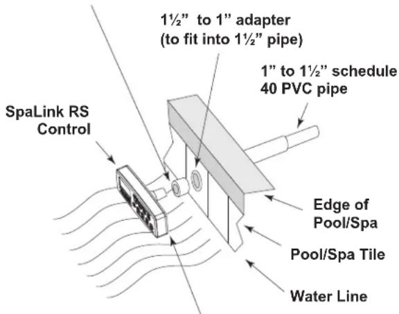
Apply 1/8" bead of silicone sealant around edge of SpaLink RS after pushing it into place.
Figure 1. Installation on a Vertical Surface
- Apply a silicone sealant around the edge of the cone-shaped base of the SpaLink RS and slide it into the adapt er (if one is being used), then into the PVC. At the mounting location, press (do not screw) the SpaLink RS into the PVC. Place a 18 " bead of silicone seal ant around the back of the SpaLink RS and let cure.
NOTE Do not alter the SpaLink RS hous ing. Cut ting the hous ing may damage its seal and will void the warranty.
3.1.2 Horizontal Installation into the Deck

WARNING
The positioning and location of the spa side control should be selected to avoid a tripping hazard which can result in injury.
- To house the SpaLink RS, plumb a 6" long piece of 1½" or 1" Schedule 40 PVC pipe as shown in Figure 2. A 1½" to 1" adapter is in clud ed for use if 1½" PVC is being used. Care fully trim the end of the pipe flush with the deck after all the deck work is com plet ed. Leave at least 2" of clear ance around the con duit from coping stones or other raised objects.
NOTE Remove "O" rings before pressing SpaLink RS into a 1" hole in an acrylic spa or wood deck. Use the adapter to secure the SpaLink RS in place from under the deck. - Install a reducer to the end of the 6" piece of pipe and run a 12 " or 34 " electrical conduit under ground from the reducer to the AquaLink RS Power Center location (refer to the AquaLink RS Installation Manual for further details on the Power Center). Use sweep elbows for turns so that the SpaLink RS cable can be easily pulled through later.
- Use an electrician's snake (or similar tool) to pull the SpaLink RS cable through the conduit to the Power Center. At the Power Center, feed the SpaLink RS cable into the low voltage com part ment (left-hand side). Strip the cable jacket 4" and strip each wire 14 ". Use the Wiring Diagram on the inside of the Power Center door to piggyback (double-up) the SpaLink RS wires with the 4-pin terminal bar.
- Apply a silicone sealant around the edge of the cone-shaped base of the SpaLink RS and slide it into the adapt er (if one is being used), then into the PVC. At the mounting location, press (do not screw) the SpaLink RS into the PVC. Place
a 18 " bead of silicone seal ant around the back of SpaLink RS and let cure.
NOTE Do not alter the SpaLink RS hous ing. Cut ting the housing may damage its seal and will void the warranty.
3.2 Installation of SpaLink RS with Snap-on Frame without Mud Box
3.2.1 Vertical and Horizontal Installation Flush Mounted into a Wood Deck

WARNING
The positioning and location of the spa side control should be selected to avoid a tripping hazard which can result in injury.
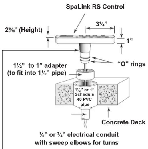
Apply silicone sealant around boss before sliding it into adapter and PVC
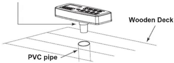
NOTE: Apply 1/8" bead of silicone sealant around edge of SpaLink RS after pushing into place.
Figure 2. Installation on a Horizontal Concrete Deck
- Use the template in Section 8 to position and mark the opening to be cut through the mounting surface. Run a 12 " or 34 " electrical conduit from a position adjacent to this hole to the AquaLink RS Power Center location. Use sweep elbows for turns so that the SpaLink RS cable can be easily pulled through later.
- IMPORTANT - Install the snap-on frame onto the SpaLink RS. Securely fasten the cable ties provided around the "T" bars of the frame legs. The cable ties provide additional support and prevent the SpaLink RS from slipping out of the frame.
- Use an electrician's snake (or similar tool) to pull the SpaLink RS cable through the conduit to the Power Center. At the Power Center, feed the SpaLink RS cable into the low voltage com part ment (left-hand side). Strip the cable jacket 4" and strip each wire 14 ". Use the Wiring Diagram on the inside of the Power Center door to piggyback (double-up) the SpaLink RS wires with the 4-pin terminal bar.
- Apply a 14 " to 38 " diameter bead of silicone sealant all around the part at the corner shown below in Figure 3. Position the SpaLink RS within the opening and temporarily tape the SpaLink RS control to the correct position. Allow 24 hours for the sealant to cure, then remove the tape.
NOTE Do not alter the SpaLink RS housing. Cutting the housing may damage its seal and will void the warranty.
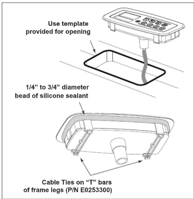
Figure 3. Flush Mount Installation on a Wood Deck
IMPORTANT
Wood must be dry before sealant is applied.
3.3 Installation of SpaLink RS with Snap-on Frame with Mud Box
3.3.1 Vertical Surface Installation with Optional Mud Box
NOTE Order part no. 7940 SpaLink RS Mud Box for use with tile or concrete.

WARNING
The positioning and location of the spa side control should be selected to avoid a tripping hazard which can result in injury.
- Refer to Figure 4 to install the optional mud box for use with concrete or tile.
- Install a reducer from the end of the 1" Schedule 40 PVC pipe and run a 12 " or 34 " electrical conduit underground from the reducer to the AquaL ink RS Power Center location. Use sweep elbows for turns so that the SpaLink RS cable can be easily pulled through later.
- Install the snap-on frame onto the SpaLink RS.
NOTE When using the mud box, do not install the cable ties provided.
-
Use an electrician's snake (or similar tool) to pull the SpaLink RS cable through the conduit to the Power Center. At the Power Center, feed the SpaLink RS cable into the low voltage com part ment (left side). Strip the cable jacket 4" and strip each wire 14 ". Use the Wiring Di a gram on the inside of the Power Center door to piggyback (double-up) the SpaLink RS wires with the 4-pin terminal bar.
-
Apply a 14 " to 38 " diameter bead of silicone sealant all around the part at the corner shown below in Figure 4. Position the SpaLink RS, secured in the snap-on frame, within the mud box and temporarily tape the SpaLink RS control into the correct position. Allow 24 hrs for the sealant to cure, then remove the tape.
NOTE Do not alter the SpaLink RS housing. Cutting the housing may damage its seal and will void the warranty.
3.3.2 Horizontal Surface Installation with Optional Mud Box
NOTE Order part no. 7940 SpaLink RS Mud Box for use with tile or concrete.

WARNING
The positioning and location of the spa side control should be selected to avoid a tripping hazard which can result in injury.
- Refer to Figure 5 to install the optional mud box for use with concrete or tile.
CAUTION
A 1/2" inside di am e ter drain tube must be connected to the mudbox to eliminate any standing water around the control. See SpaLink RS Mud Box for horizontal surface installation instructions as shown in Figure 5.
- Install a re duc er from the end of the 1" Schedule 40 PVC pipe and run a 12 " or 34 " elec tri cal con duit un der ground from the reducer to the AquaLink RS Pow er Center location. Use sweep el bows for turns so that the SpaLink RS cable can be easily pulled through later.
- Install the snap-on frame onto the SpaLink RS.
NOTE When using the mud box, do not install the cable ties provided.
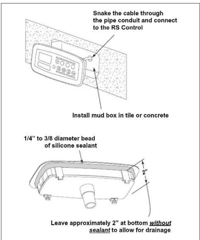
Figure 4. Vertical Installation with Optional Mud Box
- Use an electrician's snake (or similar tool) to pull the SpaLink RS cable through the conduit to the Power Center. At the Power Center, feed the SpaLink RS cable into the low voltage com part ment (left side). Strip the cable jacket 4" and strip each wire ¼". Use the Wiring Di a gram on the inside of the Power Center door to piggyback (double-up) the SpaLink RS wires with the 4-pin terminal bar.
- Apply a 14 " to 38 " diameter bead of silicone sealant all around the part at the corner shown below in Figure 5. Position the SpaLink RS, secured in the snap-on frame, within the mud box and temporarily tape the SpaLink RS control into the correct po si tion. Allow 24 hrs for the sealant to cure, then remove the tape.
NOTE Do not alter the SpaLink RS housing. Cutting the housing may damage its seal and will void the warranty.
3.4 Installation of SpaLink RS Flush Mount Mud Box
3.4.1 Rough-in Installation on a Vertical Wall
NOTE Order part no. 7940 SpaLink RS Mud Box for use with tile or concrete.
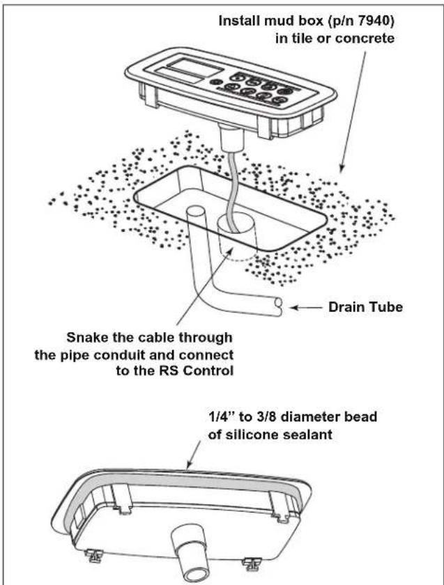
Figure 5. Horizontal Installation with Optional Mud Box
NOTE These in struc tions are for installing the SpaLink RS Flush Mount Mud Box. The mud box is for use with the new style SpaLink RS that is provided with a matching snap-on frame. The mud box will not work with the earlier version of SpaLink RS.
- Locate position to install mud box. The mud box face must be installed flush to the finished surface. It may be installed up to 14 " underflush to finished surface.
NOTE The mud box must be installed above the normal water line.
NOTE Leave the foam insert in place during construction.
- Prime a 1" Schedule 40 PVC pipe for wiring conduit and the inside PVC fi tting located on the bottom of the mudbox using Oatey® Primer 30752. Install the PVC pipe to the mudbox using primer Oatey Cement 30834. Allow to cure for 24 hours to secure properly. Reduce to 12 " or 34 " and connect to electrical conduit with sweep elbows for run back to the AquaLink RS Pow er Center location. Sweep el bows allow for turns so that the SpaLink RS cable can be easily pulled through later.
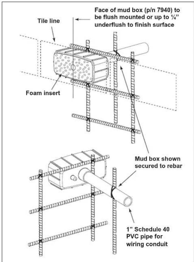
Figure 6. Vertical Wall Rough-in Installation
- Apply a 14 " to 38 " diameter bead of silicone sealant around the mud box. Position and secure the mud box in place. Figure 6 shows mud box secured to rebar.
3.4.2 Rough-in Installation on a Horizontal Surface
NOTE Order part no. 7940 SpaLink RS Mud Box for use with tile or concrete.
NOTE These in struc tions are for installing the SpaLink RS Flush Mount Mud Box. The mud box is for use with the new style SpaLink RS that is provided with a matching snap-on frame. The mud box will not work with the earlier version of SpaLink RS.
- Locate position to install mud box. The mud box face must be installed flush to the finished surface. It may be installed up to 14 " underflush to finished surface.
NOTE Leave the foam insert in place during construction.
- Cut the end of the drain boss on mud box and attach 12 " I.D. plastic tubing. Route tubing to a suitable location to allow the control box to drain.
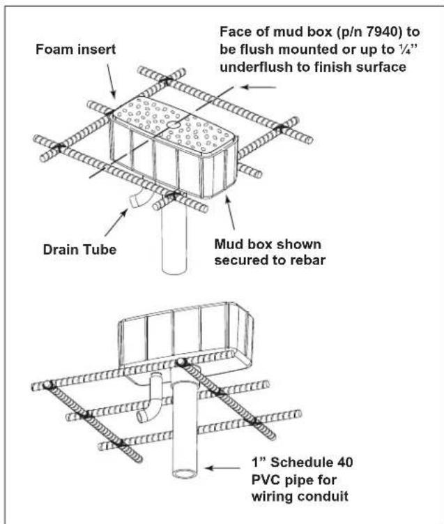
Figure 7. Horizontal Surface Rough-in Installation
-
Prime a 1" Schedule 40 PVC pipe for wiring conduit and the inside PVC fi tting located on the bottom of the mudbox using Oatey® Primer 30752. Install the PVC pipe to the mudbox using primer Oatey Cement 30834. Allow to cure for 24 hours to secure properly. Reduce to 12 " or 34 " and connect to electrical conduit with sweep elbows for run back to the AquaLink RS Pow er Center location. Sweep el bows allow for turns so that the SpaLink RS cable can be easily pulled through later.
-
Apply a 14 " to 38 " diameter bead of silicone sealant around the mud box. Position and secure the mud box in place. Figure 7 shows mud box secured to rebar.
Section 4. Wiring Configuration
4.1 Bonding
Install the washer, bonding lug, and screw (included with the SpaLink RS package) to the Power Center enclosure. Connect the bond lug, using a #8 (minimum) solid copper core wire, to an approved earth ground (an approved ground stake, grid, or conducting metal water pipe buried to a suffi cient depth).

WARNING
The bonding connection from the Power Center cabinet to an approved earth ground is intended to minimize the potential hazard of electrical shock to the user. To properly and safely wire the system, be sure to carefully follow the applicable requirements of the National Electrical Code (NEC), NFPA 70 or the Canadian Electric Code (CEC), CSA C22.1. All applicable local installation codes must also be adhered to.
4.2 Control Wiring
The wires coming from the SpaLink RS can be “doubled up” on the red terminal bar with the four wires coming from the Indoor Controller.
NOTE If you are installing more than two wires in each terminal, order and use a Jandy Multiplex PCB Kit (p/n 6584). Never put more than two wires into each of the pins of the terminal bar.
Up to three SpaLink RS Con trols can be in stalled on one AquaL ink RS system. Each SpaLink RS installed must be uniquely “addressed” for the system to properly recognize it. This is done by changing the white wire con nec tion for each SpaLink RS installed. Follow the guide below:
First SpaLink RS - White wire paired with green wire
Second SpaLink RS - White wire paired with red wire
Third SpaLink RS - White wire not installed (cut off and cap end of wire)
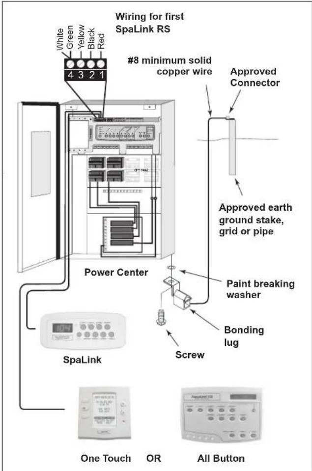
Figure 8. Wiring Configuration
Section 5. SpaLink RS Operation
If Rev. G fi rmware is installed on the RS Power Center PCB, three dashed lines across the L.E.D. display indicate that the spa is not on. If Rev. H fi rmware or later is installed, the display will read “OFF”. To display water tem per a ture, turn on the spa. It takes approximately 60 seconds for the watertemperature to appear.
Three dots at the bottom of the L.E.D. display indicate that the display is in “Sleep” mode. To wake up the display, press the Temp Display button.
When the spa is on, press the Temp Display button to cycle the display from Water Temperature of the spa to "Sleep" mode, to Thermostat Setting, and then to Air Temperature.
When the spa is on and the thermostat mode is activated, the display will flash. The temperature setting can then be changed by pressing the up or down arrows. The maximum temperature is 104^ .
When Air Temperature is displayed, the L.E.D. in the upper right hand corner of the display will be lit.
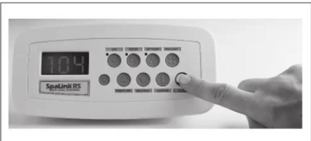
Figure 9. Operating the SpaLink RS Buttons
| Button Button | Factory Default SettingsRS Combo and Dual Models | Button Factory Default SettingsPool or Spa Only Models |
| ○ | SPA Filter Pump | |
| ○○ | SPA HTR TEMP 1 | |
| ○○○ | AUX 1 AUX 1 | |
| ○○○○ | AUX 2 AUX 2 | |
| △ | AUX 3 AUX 3 | |
| ▽ | AUX 4 AUX 4 | |
| □ | AUX 5 AUX 5 | |
| □ | AUX 6 AUX 6 |
NOTE: At the AquaLink® RS Indoor Controller, the buttons can be "reprogrammed" to change the settings.
Section 6. Programming the SpaLink RS
6.1 Using the All Button
The All Button SpaLink RS Menu allows you to define which equipment is controlled by the but tons on the SpaLink RS. You may want to write down your SpaLink RS button assignments so that you can label the buttons on the switch with the label pack provided.
-
On the All Button, press the MENU button, then press the BACK arrow button. Scroll through the menu to SYSTEM SETUP.
-
Press ENTER. Then press FORWARD to SpaLink RS and press ENTER again.
NOTE If only one SpaLink RS is installed, press ENTER when 1 SpaLink is displayed. If a second or third SpaLink RS is installed, use the FORWARD or BACK buttons to move from 1 SpaLink to 2 SpaLinks or 3 SpaLinks. When the number of SpaLink RS units installed is displayed, press ENTER.
- The All Button display will read SELECT DEVICE FOR BUTTON 1. Press the button on the Controller for the piece of equipment that you want to control from the first button of the SpaLink RS (for example, the Spa button). It is not necessary to press ENTER after your selection.
NOTE If there is more than one SpaLink RS installed in the system, the buttons on the second SpaLink RS will be buttons 9 through 16 and the buttons on the third SpaLink RS will be buttons 17 through 24.
- Repeat this process for each remaining button on the SpaLink RS. When you have finished, the All Button display will show the settings for each button.
6.2 Using the OneTouch
Like the All Button, the OneTouch SpaLink RS Menu allows you to define which equipment is controlled by the but tons on the SpaLink RS.
-
On the OneTouch, press the DOWN arrow button to scroll down to MENU/HELP. Press SELECT.
-
Scroll through the menu to SYSTEM SETUP. Press SELECT.
-
Scroll through the menu to SPALINK and press SELECT again. The SPALINK SETUP screen appears. Scroll to the number of SpaLink RS units installed, then press SELECT.
-
The OneTouch display will read SPALINK BUTTON SETUP. Scroll to the button that you want to control on the selected SpaLink RS and press SELECT. For example, if you want to assign a piece of equipment to button 3 on the second SpaLink RS, then scroll to 2:3 and press SELECT.
NOTE The SpaLink RS button selections are designated as 1:1 through 1:8. If more than one SpaLink RS is installed in the system, the buttons on the second SpaLink RS will be 2:1 through 2:8 and the buttons on the third SpaLink RS will be 3:1 through 3:8.
-
Scroll to the piece of equipment (for example, the filter pump) that you want to assign to the selected button of the SpaLink RS and press SELECT.
-
Repeat this process for each remaining button on the SpaLink RS. When you have finished, the OneTouch display will show the settings for each button.
Section 7. Exploded View and Replacement Parts
| Dwg.# | Kit # Description Qty. | |
| 1 | 7227 SpaLink RS, Frame, CableTies (2), 150' Cable, White | 1 |
| 7489 SpaLink RS, Frame, CableTies (2), 200' Cable, White | 1 | |
| 7626 SpaLink RS, Frame, CableTies (2), 300' Cable, White | 1 | |
| 7887 SpaLink RS, Frame, CableTies (2), 150' Cable, Gray | 1 | |
| 7890 SpaLink RS, Frame, CableTies (2), 200' Cable, Gray | 1 | |
| 7893 SpaLink RS, Frame, CableTies (2), 300' Cable, Gray | 1 | |
| 7888 SpaLink RS, Frame, CableTies (2), 150' Cable, Black | 1 | |
| 7891 SpaLink RS, Frame, CableTies (2), 200' Cable, Black | 1 | |
| 7894 SpaLink RS, Frame, CableTies (2), 300' Cable, Black | 1 | |
| 2 | 7940 Flush Mount Mud Box 1 | |
| 3 | R0552500 SpaLink RS Frame, White 1 | |
| R0552600 SpaLink RS Frame, Gray 1 | ||
| R0552700 SpaLink RS Frame, Black 1 | ||
| 4 | E0253300 Cable Ties 2 |
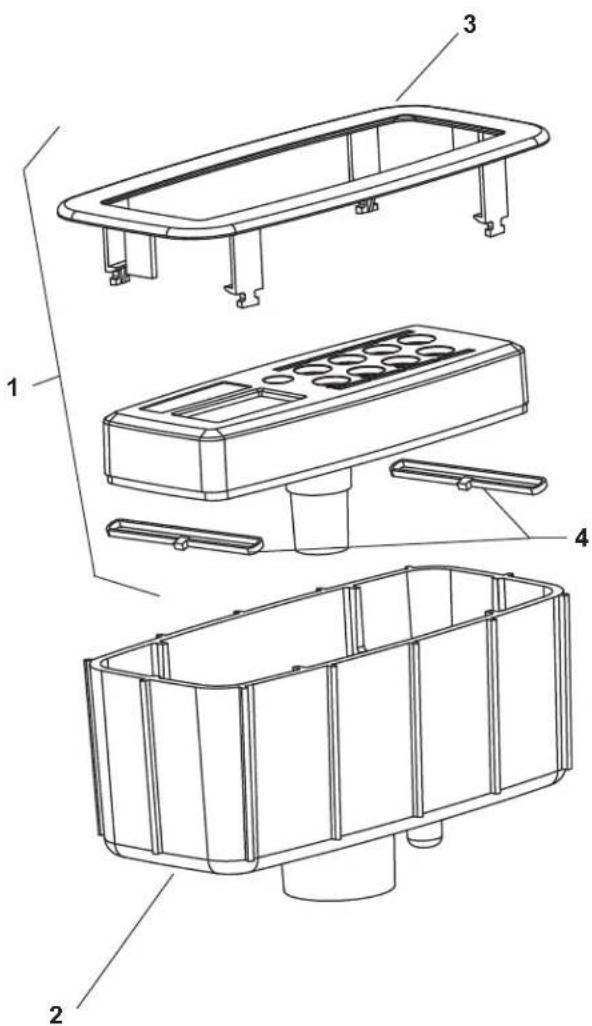
Section 8. Installation Template for SpaLink RS into Deck with Snap-on Frame Only
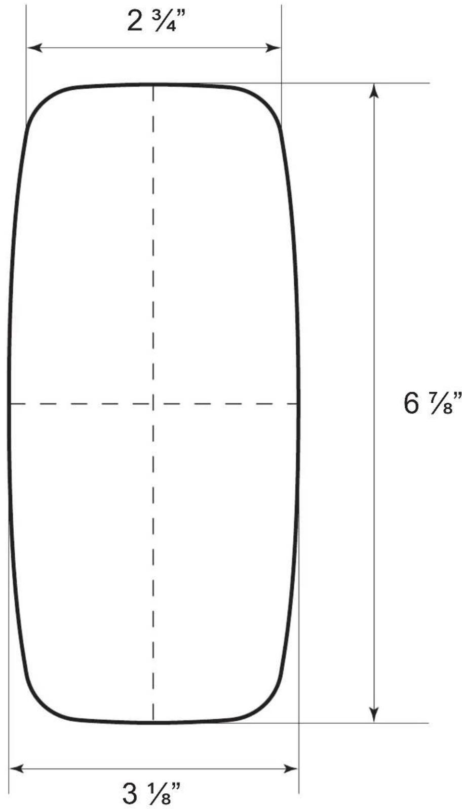
Remove page and cut out center of template. Use remaining outer tem plate to locate and mark the outline of the hole to be cut.
LIMITED WARRANTY
Thank you for purchasing Jandy ^® pool and spa products. Jandy Pool Products, Inc. warrants all parts to be free from manufacturing defects in materials and workmanship for a period of one (1) year from the date of retail purchase, with the following exceptions:
- AquaLink® RS units installed with Jandy Surge Protection Kits will be covered for two (2) years.
- Never Lube® valves are warranted for the life of pool and/or spa on which they were originally installed.
- AquaPure® Electronic Chlorine Generator Electrolytic Cells carry a five (5) year limited warranty on a prorated basis.
This warranty is limited to the first retail purchaser, is not transferable, and does not apply to products that have been moved from their original installation sites. The liability of Jandy Pool Products, Inc. shall not exceed the repair or replacement of defective parts and does not include any costs for labor to remove and reinstall the defective part, transportation to or from the factory, and any other materials required to make the repair. This warranty does not cover failures or malfunctions resulting from the following:
- Failure to properly install, operate or maintain the product(s) in accordance with our published Installation, Operation and Maintenance Manuals provided with the product(s).
- The workmanship of any installer of the product(s).
- Not maintaining a proper chemical balance in your pool and/or spa [pH level between 7.2 and 7.8, Total Alkalinity (TA) between 80 to 120 ppm, Total Dissolved Solids (TDS) less than 2000 not including salt ppm].
- Abuse, alteration, accident, fire, flood, lightning, rodents, insects, negligence or acts of God.
- Scaling, freezing, or other conditions causing inadequate water circulation.
- Operating the product(s) at water flow rates outside the published minimum and maximum specifications.
- Use of non-factory authorized parts or accessories in conjunction with the product(s).
- Chemical contamination of combustion air or improper use of sanitizing chemicals, such as introducing sanitizing chemicals upstream of the heater and cleaner hose or through the skimmer.
- Overheating; incorrect wire runs; improper electrical supply; collateral damage caused by failure of O-Rings, DE grids, or cartridge elements; or damage caused by running the pump with insufficient quantities of water.
LIMITATION OF LIABILITY:
This is the only warranty given by Jandy Pool Products, Inc. No one is authorized to make any other warranties on behalf of Jandy Pool Products, Inc. THIS WARRANTY IS IN LIEU OF ALL OTHER WARRANTIES, EXPRESSED OR IMPLIED, INCLUDING BUT NOT LIMITED TO ANY IMPLIED WARRANTIES OF FITNESS FOR A PARTICULAR PURPOSE AND MERCHANTABILITY. JANDY POOL PRODUCTS, INC. EXPRESSLY DISCLAIMS AND EXCLUDES ANY LIABILITY FOR CONSEQUENTIAL, INCIDENTAL, INDIRECT OR PUNITIVE DAMAGES FOR BREACH OF ANY EXPRESSED OR IMPLIED WARRANTY. This warranty gives you specific legal rights. You may also have other rights that vary by state or province.
WARRANTY CLAIMS:
For prompt warranty consideration, contact your dealer and provide the following information: proof of purchase, model number, serial number and date of installation. The installer will contact the factory for instructions regarding the claim and to determine the location of the nearest designated service center. If the dealer is not available, you can locate a service center in your area by visiting www.jandy.com or by calling our technical support department at (707) 776-8200 extension 260. All returned parts must have a Returned Material Authorization number to be evaluated under the terms of this warranty.
- Installation and Operation Manual
- SpaLink® RS
- Function Spa Side Remote
- WARNING
- Table of Contents
- Section 1. Important Safety Instructions ... 4
- Section 2. Product Description ......6
- Section 3. Installation Instructions ...... 6
- Section 4. Wiring Configuration ...... 11
- Section 5. SpaLink RS Operation .... 12
- Section 6. Programming the SpaLink RS ....13
- Section 7. Exploded View and Replacement Parts ....14
- Section 8. Installation Template for SpaLink RS into Deck with Snap-on Frame Only ....15
- EQUIPMENT INFORMATION RECORD
- Section 1. Important Safety Instructions READ AND FOLLOW ALL INSTRUCTIONS
- DANGER
- To Reduce the Risk of Injury -
- AVERTISSEMENT
- CAUTION
- SAVE THESE INSTRUCTIONS
- Section 2. Product Description
- NOTE For use with an AquaLink® RS System ONLY!
- Dimensions of SpaLink RS without Frame
- Section 3. Installation Instructions
- Installation of SpaLink RS without Snap-on Frame (Surface Mount)
- Vertical Installation into the Spa Wall
- Horizontal Installation into the Deck
- Installation of SpaLink RS with Snap-on Frame without Mud Box
- Vertical and Horizontal Installation Flush Mounted into a Wood Deck
- IMPORTANT
- Installation of SpaLink RS with Snap-on Frame with Mud Box
- Vertical Surface Installation with Optional Mud Box
- Horizontal Surface Installation with Optional Mud Box
- Installation of SpaLink RS Flush Mount Mud Box
- Rough-in Installation on a Vertical Wall
- Rough-in Installation on a Horizontal Surface
- Section 4. Wiring Configuration
- Bonding
- Control Wiring
- Section 5. SpaLink RS Operation
- Section 6. Programming the SpaLink RS
- Using the All Button
- Using the OneTouch
- Section 8. Installation Template for SpaLink RS into Deck with Snap-on Frame Only
- LIMITED WARRANTY
- LIMITATION OF LIABILITY:
- WARRANTY CLAIMS:
Brand : Jandy
Model : SpaLink RS
Category : Contrôle de spa