
GL500 - Water pump Global Water - Free user manual and instructions
Find the device manual for free GL500 Global Water in PDF.


| Type | Data Logger |
| Brand | Global Water |
| Model | GL500 |
| Power Supply | 4.2 VDC min to 24.0 VDC max |
| Standby Current | 70 µA typical |
| Logging Current | 5 mA typical + sensor current |
| Operating Temperature | -40°C to +85°C |
| Analog Sensor Inputs | 7 channels, 4-20 mA (0-5 VDC optional), 12-bit resolution |
| Digital Inputs | 2 independent pulse counters, max 100 Hz, 16-bit |
| Sample Modes | Fixed interval (1 sec to >1 year), high speed (10/sec), logarithmic, exception logging |
| Storage Capacity | 40,879 recordings with time stamp |
| Communication Ports | RS-232 DB9, USB Type B |
| Baud Rates | 9600, 19200, 28800, 38400, 57600, 115200, auto-detect or fixed |
| Software | Global Logger Interface for Windows 98/ME/2000/XP/Vista/7 |
| Warranty | One year from shipment |
| Dimensions | Not specified in manual, typical enclosure size |
| Weight | Not specified in manual, typically < 1 kg |
Frequently Asked Questions - GL500 Global Water
User questions about GL500 Global Water
0 question about this device. Answer the ones you know or ask your own.
Ask a new question about this device
Download the instructions for your Water pump in PDF format for free! Find your manual GL500 - Global Water and take your electronic device back in hand. On this page are published all the documents necessary for the use of your device. GL500 by Global Water.
USER MANUAL GL500 Global Water
GL500-7-2 Data Logger

natural_image
Simple black-and-white icon with a stylized wave and rounded rectangle, enclosed in a rounded square border (no text or symbols)Global Water
Instrumentation, Inc.
11390 Amalgam Way
Gold River, CA 95670
T: 800-876-1172
Int'l: (916) 638-3429, F: (916) 638-3270
globalw@globalw.com
11/30/09
01-401

Global Water
800-876-1172 • globalw.com
Congratulations on your purchase of a Global Water GL500 Data Logger. This instrument has been quality tested and approved for providing accurate and reliable measurements. We are confident that you will find the logger to be a valuable asset to your applications. Should you require assistance, our technical staff will be happy to help.
Table of Contents
| I. | Checklist | □ | □ | □ | □ | □ | 3 |
| II. | Inspection | □ | □ | □ | □ | 3 | |
| III. | Warranty | □ | □ | □ | □ | □ | 3 |
| IV. | GL500 Specification | □ | □ | □ | □ | 4 | |
| V. | System Requirements | □ | □ | □ | 5 | ||
| VI. | Software Installation | □ | □ | □ | □ | 5 | |
| VII. | Direct Connection | □ | □ | □ | □ | 8 | |
| VIII. | Modem Connection | □ | □ | □ | □ | 10 | |
| IX. | Main Screen | □ | □ | □ | □ | □ | 12 |
| X. | On-Line Help Files | □ | □ | □ | □ | 16 | |
| XI. | Get History | □ | □ | □ | □ | □ | 17 |
| XII. | Setup Menus | □ | □ | □ | □ | □ | 18 |
| XIII. | General Setup | □ | □ | □ | □ | □ | 19 |
| XIV. | Analog Setup | □ | □ | □ | □ | □ | 22 |
| XV. | Digital Setup | □ | □ | □ | □ | □ | 25 |
| XVI. | Programming | □ | □ | □ | □ | □ | 27 |
| XVII. | Connections | □ | □ | □ | □ | □ | 28 |
| XVIII. | Modem Cable Diagrams | □ | □ | □ | 29 | ||
| XIX. | Maintenance | □ | □ | □ | □ | □ | 30 |
| XX. | Troubleshooting | □ | □ | □ | □ | 30 | |
| XXI. | Customer Support | □ | □ | □ | 31 | ||
| XXII. | CE Certification | □ | □ | □ | □ | 32 |

Global Water
800-876-1172 • globalw.com
I. Checklist:
a. GL500 Data Logger
b. GL500 Data Logger Manual
c. RS-232 Serial Cable
d. USB Cable, Type A to B
e. Global Logger Interface Software CDROM
II. Inspection:
a. Your Data Logger was carefully inspected and certified by our Quality Assurance Team before shipping. If any damage has occurred during shipping; please notify Global Water Instrumentation, Inc. and file a claim with the carrier involved.
III. Warranty:
a. Global Water Instrumentation, Inc. warrants that its products are free from defects in material and workmanship under normal use and service for a period of one year from date of shipment from factory. Global Water's obligations under this warranty are limited to, at Global Water's option: (I) replacing or (II) repairing; any products determined to be defective. In no case shall Global Water's liability exceed the products original purchase price. This warranty does not apply to any equipment that has been repaired or altered, except by Global Water Instrumentation, Inc., or which has been subject to misuse, negligence or accident. It is expressly agreed that this warranty will be in lieu of all warranties of fitness and in lieu of the warranty of merchantability.
b. The warranty begins on the date of your invoice.

Global Water
800-876-1172 • globalw.com
IV. GL500 Specification:
Power Supply: Voltage: 4.2 VDC Min. to 24.0 VDC Absolute Maximum
Standby Current: 70uA Typical
Logging Current: 5mA Typical + sensor current
Operating Temperature Industrial, -40°C to +85°C (Battery may not apply)
Analog Sensor Inputs: 4-20mA (0-5VDC as factory option)
Resolution: 12-Bit, 4096 Steps
7 Input channels + battery voltage monitor
Sensor Warm-up Time: Programmable, 0-60 Seconds
Digital Inputs: 2 Independent pulse counters
Maximum Input Voltage: 24VDC
Maximum Frequency: 100Hz
Minimum Pulse Width: 2mS
Maximum Count: 65,535 (16-Bit)
Sample Now Input: Sample-on-Demand input, software enabled
Maximum Input Voltage: 24VDC
Minimum Pulse Width: 2mS
Sample Modes: Fixed Interval: Programmable from 1 Sec. to >1 Year
High Speed: 10 Samples per second
Logarithmic Sample Rate (Approximation)
Exception (Log only on deviation from previous n
Storage Capacity: 40,879 Recordings for all inputs plus time stamp
Communication Ports: RS-232 DB9 or USB Type B
Selectable Baud Rates:
9600, 19200, 28800, 38400, 57600, 115200
Auto Detect or Fixed Ra

Global Water
800-876-1172 • globalw.com
V. System Requirements:
Desktop or Laptop computer with:
1) Windows 98, ME, 2000, XP Vista or Windows 7 Operating Systems
2) CDROM Drive
3) RS-232 or USB Port
Note that the software provided with the GL500 data logger is for running on desktop and laptop computers only. Software for many popular Handheld PDA devices is available from Global Water. Special cables may be required.
VI. Software Installation:
Global Logger Installation: This software is for use on Windows based desktop and laptop computers only. Insert the software installation CD and run the Setup program. This will install the Global Logger application in the Program Files folder and automatically put the Global Logger icon on the desktop.
Serial communication: If you are using the RS-232 serial port to access the data logger, no further action is needed. You can start using the logger by opening the Global Logger application program. If you plan to use the USB port, you must install the driver. You may consider installing the driver now, even if you plan to use the serial port.
USB Driver Installation: With the installation CD in the CDROM drive and DC power applied to the logger, plug the USB cable into the data logger to open the ADD New Hardware Wizard. The menus that follow will look different for different operation systems but the procedure is the same. Do not allow the Hardware Wizard to automatically search for the driver. Instead, specify the location (CDROM). If a generic driver gets, or has been previously installed, it must be uninstalled before proceeding by using the Add or Remove Programs section of the Control Panel. Instead, click the Search External Media box or Specify a Location box and install the driver from the CDROM. Running the Setup program that installs the Global Logger software also installs a folder with the driver in it. This location can also be specified if the CDROM is not available; although, it is recommended that the driver be installed at the same time the Global Logger is installed.

Global Water
800-876-1172 • globalw.com
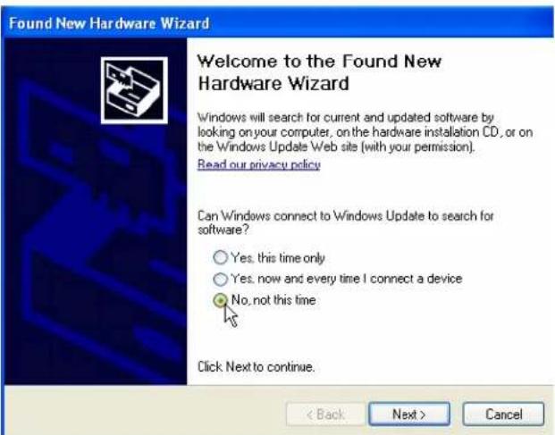
The following menus apply to the Windows XP operating system.
1) Do not let Windows search for software. Click "No, not at this time" when asked if Windows Update can search for software.
Click Next.
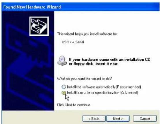
2) Do not let Windows automatically install the software. Click "Install from a specific location".
Click Next.
3) Specify the location of the driver. Make sure the Global Logger CDROM is in the CD drive and click "Search removable media" only.
Click Next.


Global Water
800-876-1172 • globalw.com
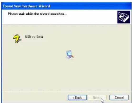
4) The Hardware Wizard searches for the driver.
If Windows advises that the software is not certified, click:
"Continue Anyway".
This only means that Microsoft has not licensed the software. Second party software is allowed and no harm will come to your computer.
5) The first half of the installation is complete. The Hardware Wizard may need to make two passes.
Click Finish.

6) Two drivers are sometimes required so the Hardware Wizard may repeat the exact same process again. As before; a: do not let the Windows Update do a search, b: tell Windows to search from a specific location instead of automatically installing software, c: tell Windows to search from removable media (CDROM).
7) The installation is complete.
Click Finish.


Global Water
800-876-1172 • globalw.com
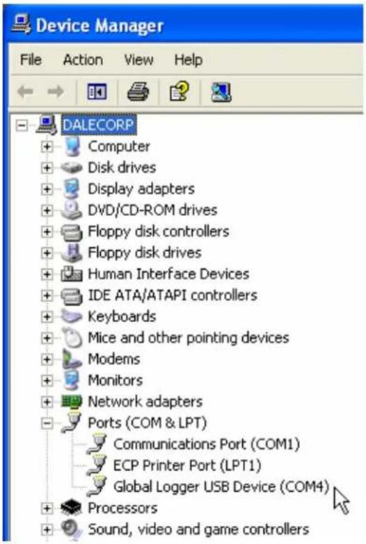
8) To confirm the installation, look in the Device Manager and find the USB Serial Port. The COM setting following that will show the virtual COM port that has been automatically assigned to the driver. As you will see in the following section, this COM port will be automatically detected by the Global Logger software so it is not necessary to note which port is being used by the driver.
VII. Direct Connection:
Important: This data logger supports an Auto Baud Rate Mode which automatically detects the communication speed. However; this communication software also supports loggers which may be programmed in a Fixed Baud Rate Mode. This is useful in telemetry applications, particularly when using Global Water data loggers with our Global Access radio modem software. The upcoming discussion assumes that the logger is programmed in auto detect mode. If you cannot connect to the logger and suspect that the logger may be using a fixed rate mode; try each connection speed separately, especially 38400 which is required when using the Global Access software.

Global Water
800-876-1172 • globalw.com
There are 3 ways to connect to the GL500 data Logger, direct connection through the RS-232 serial port or USB port and dial out through an installed modem.
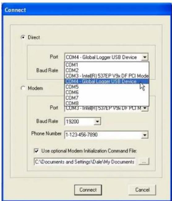

To make a direct connection to the logger, click the "Direct" option and from the "Port" menu, select the port you wish to use. For USB access select the USB serial port at the COM port the driver was assigned, which is automatically shown in the list. Serial connection is generally done through the 9-pin COM1 connector although COM2 can also be used. When an external modem or other device is assigned to COM1, the port can still be used for accessing the logger, but the external device must be disconnected. Both the serial and USB ports can be connected to the logger at the same time but you must select which of them is to be used. No difference will be noticed by the user except while downloading historical data. Because of the excessive handshaking done by the USB port, the serial port will run about 50% faster at the same baud rate. Next, select the desired baud rate from the "Baud Rate" menu. Generally, the fastest rate of 115,200 is used although; long cables or other factors may require a slower setting. Click "Connect" to make the connection. If a connection is not made, a message will appear. Check the power connection, communication cable, driver installation and COM port settings.

Global Water
800-876-1172 • globalw.com
VIII. Modem Connection:
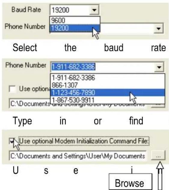
Access to the GL500 can be made through dial-out to a remote modem by clicking the "Modem" option. The connection from modem to logger requires an RS-232 serial modem, USB modems are not supported as an interface to the logger. Also, some switch settings must be made to the remote modem and an initialization string may be required to properly configure the host modem.
Two baud rates are supported 9600 and 19200. Should you experience difficulty establishing a reliable connection at 19200, use the slower connection speed. Note that due to the slower baud rates and the additional handshaking performed during modem communication, The Global Logger software will operate significantly slower than during a direct connection.
The Global Logger software will remember the last 4 numbers dialed and has a provision for using a stored text file (.txt extension) for initialization of the host modem using standard AT commands. Some experience may be required to configure your modem but a sample command file and some useful tips follow.

Select the modem's COM port

Global Water
800-876-1172 • globalw.com
Sample initialization text file:
This is for reference and applies to an external US Robotics modem only.
ATM1 ; speaker off when connects
AT&B1 ; fixed serial port rate
AT&D2 ; normal DTR
AT&H1&R2 ; h/w flow control
AT&I0 ; disable s/w flow control
AT&K0 ; disable compression
AT&M4 ; normal error control
Select the COM port for your modem and the baud rate. Type in the phone number or select it from the list of prestored numbers. If necessary, click the "Use Initialization File" box and use the browse button to search for the initialization text file for your modem. Click "Connect" and the software will dial out, showing the status screen shown above. Once a connection is established, "Connect" will appear for a few seconds along with the baud rate of the connection. After connecting, the normal Global Logger screen will appear and operate exactly as if a direct connection was made. All options and features work the same but at a reduced communication speed.

When connecting the GL500 Data Logger to an external modem, a special cable is required. Wiring diagrams are provided at the end of this manual and pre-wired cables are available from Global Water. The remote modem is configured by setting DIP switches. They should be set to auto-answer on, DTR Normal, carrier detect normal and smart mode. Global Water can provide external modems and interface cables at an additional cost if requested. Contact our sales department for more information.
It may not be necessary to use an initialization string to configure the host modem but if problems arise the modem should be set with software handshaking off (Xoff), DTR normal, fixed baud rate, compression off and error correction on. This configuration is done by building an initialization file using the standard AT commands and loading it into the connection screen. Global Water suggests that you test the modems operation before installing in the field.

Global Water
800-876-1172 • globalw.com
IX. Main Screen:
The main screen is where the status and option menus are accessed. The GL500 data logger will continue to log at normal intervals while connected to the Global Logger software. While connected, the logger will draw an addition current from the power supply of 5-10mA so it is advised that, if you are operating on battery power and plan not to access the logger for extended periods of time, you disconnect to increase battery life. Interface cables may remain connected. To disconnect, click on the “Disconnect” button. This label on this button will change to “Connect” and clicking on it will return you to the connection screen as previously discussed.

bar
Global Logger v2.0.6 | Sample | Continuously | Disconnect | Get Sample | Get History | Clear History | Sync Time | Setup | | :--- | :--- | :--- | :--- | :--- | :--- | :--- | :--- | | 1 | -58.0 Temp F | 88.1 | 88.0 | 88.5 | 88.7 | 89.0 | 122.0 | | 2 | 100.00 Humidity% | 22.18 | 22.18 | 22.28 | 22.31 | 22.41 | 100.00 | | 3 | 0.0 WindMPH | 7.7 | 7.7 | 7.8 | 7.8 | 7.9 | 110.0 | | 4 | 0.0 WindDeg | 168.0 | 167.9 | 168.6 | 168.7 | 169.2 | 360.0 | | 5 | 0 W/M3 | 984 | 983 | 987 | 988 | 991 | 1500 | | 6 | 28.00 inHg | 30.15 | 30.15 | 30.16 | 30.16 | 30.17 | 32.00 | | 7 | 4.00 mA | 17.03 | 17.02 | 17.07 | 17.08 | 17.11 | 20.00 | | 8 | 0.00 Volts | 12.63 | 12.62 | 12.66 | 12.67 | 12.69 | 24.00 | Pulse Channel 1: 0.00 Inches; Pulse Channel 2: 0 Pulses; Alarm 1: 8:36:00 AM; Alarm 2: 12:00:00 AMThe functions and information in this screen are discussed in the following sections.

Global Water
800-876-1172 • globalw.com
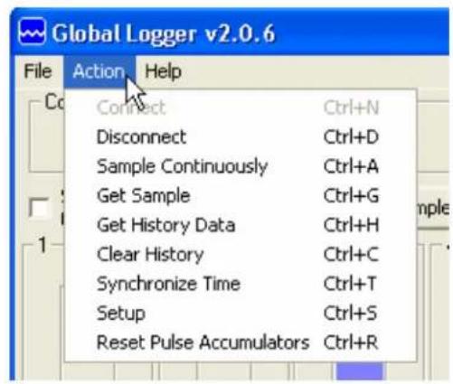
Tool Bar: The tool bar at the top of the screen has 3 options; File, Action and Help. In this screen, the File option is used to exit the program only. Action allows a menu driven interface to the various functions and displays the hot-keys, which can be used for fast access. In the Help menu; Help allows you to view the on-line help files (see section X, Page 16), About shows contact information and Revision information for the Global Logger software and Firmware Version displays the GL500 Data Logger revision number.


COM Status: This reads "Connected" in green or "Not Connected" in red, depending on the current connection status.
Logger Name: The logger name is a user defined name associated with a particular logger to identify one from another. It is programmed in the Setup menu as described later and is limited to 32 characters.
Logger Time: The time and date displayed is that of the real-time clock in the logger. It is only updated upon initial connection and certain functions that cause data to be read from the logger. These include Sample Continuously, Get Sample, Sync Time and Setup whose functions are to be described later.
Interval: This field displays the logging mode. "Fast" indicates high-speed mode and "Logarithmic" is shown in logarithmic mode. If the logger is in the normal fixed interval sampling mode, the time between samples will be displayed. These modes are to be described later.
Warmup: This displays the sensor warm-up time.

Global Water
800-876-1172 • globalw.com
Records: This field indicates the number of data recordings in memory.
Logging State: This shows whether the GL500 is currently logging waiting to be started or stopped by the alarm timers. These features are described in detail later.
Sample Continuously: Clicking this check box causes the Global Logger software to take and display a real-time reading once per second until stopped by clicking it again, as well as update the rest of the fields on the screen. These data readings are not stored in the historical record and do not affect the normal recording of the logger. The initial reading has a sensor warm-up time of 50mS and the sensor is left powered up until this feature is turned off.
Get Sample: Clicking this button causes the Global Logger software to take and display a single reading as well as update the rest of the fields on the screen. This data reading is not stored in the historical record and does not affect the normal recording of the logger. The sensor warm-up time is fixed at 50mS.
Get History: This button starts the download of all the historical data stored in the logger memory. Oldest data is collected first and Clicking "Stop" halts the process. This function is described in detail later.
Clear History: This resets the number of recordings in memory to zero. The user is warned first and must confirm the action before the memory is cleared.

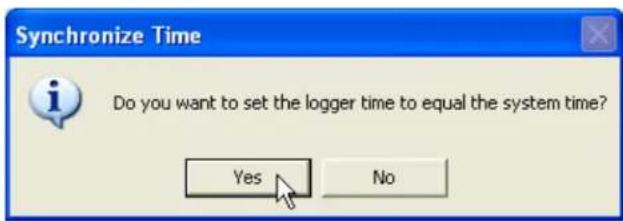
Sync Time: This button causes the data logger's internal clock to be set to the system time of the computer it is connected to. The user is warned first and must confirm the action before the time is set.
Setup: Clicking this button enters the setup screen where the user can change and program all parameters into the data logger. This function is described in detail later.

Global Water
800-876-1172 • globalw.com
Bar Graphs: The bar graphs show a visual representation of the most recent data reading taken by using the Sample Continuously or Get Sample functions. The upper and lower limits of the display are defined by the user as discussed in detail later.
Numerical Reading: The numerical reading at the bottom of the bar graph shows the actual data reading and is updated at the same time as the bar graph.
Successive numerical readings taken by using Sample Continuously or Get Sample are shown in a list below the bar, up to 5.
Pulse channels: The GL500 Data Logger has two independent pulse channels, each with a maximum count of 65,535. At the time of the logger's normal sampling interval, the counts are stored in memory along with the other sensor data and time stamp, and then the counters are set to zero to start the counting sequence over again. The Pulse Channel 1 and Pulse Channel 2 fields show how many pulses have been counted since the last logger recording for each of the 2 pulse channels. For example: If the logger is set to record once per minute and it is put into Sample Continuously mode, the display will be updated once per second and as pulses are applied to the pulse inputs, the Pulse Channel fields will update the count. At the end of the normal one minute sampling interval, the total number of pulses will be stored in memory and the Pulse Channel fields will show zero until more pulses are applied. Note that the pulse channels can be scaled to show rainfall, water flow etc. by multiplying the count by a user definable number as described in detail later.
Alarm 1: This field shows the time that the logger is set to start logging. The start alarm is a 24-hour timer which will initiate logging, when enabled, at the next occurrence of that time.
Alarm 2: This field shows the time that the logger is set to stop logging. The stop alarm is a 24-hour timer which will halt logging, when enabled, at the next occurrence of that time after the logger has started recording. If the Alarm 1 timer is set to initiate logging, the Alarm 2 timer will halt logging at the next occurrence of the Alarm 2 time after the logger has been started by Alarm 1. If the Alarm 1 timer is not enabled, the Alarm 2 timer will halt logger on the next occurrence of that time.
Note: Use care when programming the alarm times. If left enabled, changing and reprogramming any of the setup parameters will restart the alarm timers.

Global Water
800-876-1172 • globalw.com
X. On-Line Help Files:
Clicking on Help displays the on-line help files which contain all of the information contained in this manual. There are 3 ways to access the information. The first tab is Contents which accesses the table of contents for the manual. Clicking on any of the topics opens up the
body of text on that subject. Within each body of text is a discussion of that subject and links to related topics underlined in blue. Clicking on the link will bring up a new window with specific information on that topic. In this case, Sensor Warm-up time in the General Setup menu.


Click the Index tab to find a listing of topics. Type letters into the keyword field and the program automatically sorts the topics alphabetically. To find relevant topics based on a keyword, click the Search tab. Type in a keyword and click List Topics. When the desired topic is found, double-click on it or click Display at the bottom of the screen to show information on that subject.

Global Water
800-876-1172 • globalw.com
Xl. Get History:
Clicking the Get History button begins the downloading of the historical data into an information screen. This screen allows the viewing of the recorded data and also provides a path to export the data to an Excel compatible file. Note that the logger continues to log as data is downloaded. Thus, more data points may be downloaded than originally indicated.

other
Historical Data Viewer Logger Name American River - Pump Station 2 Records Retrieved 1490 Date / Time Volts Volts Volts mA mA mA 10/4/06 07:04:12 2.534 1.250 1.162 6.535 16.775 15.683 10/4/06 07:04:34 2.533 1.250 1.162 6.530 16.760 15.678 10/4/06 07:05:09 2.533 1.249 1.161 6.525 16.760 15.673 10/4/06 07:05:55 2.532 1.249 1.161 6.520 16.746 15.663 10/4/06 07:07:46 2.538 1.251 1.164 6.540 16.795 15.708 10/4/06 07:12:46 2.529 1.248 1.160 6.520 16.741 15.653 10/4/06 07:17:46 2.526 1.246 1.159 6.510 16.721 15.633 10/4/06 07:22:46 2.516 1.242 1.155 6.490 16.656 15.579 10/4/06 07:27:46 2.516 1.242 1.154 6.485 16.651 15.574 10/4/06 07:32:46 2.516 1.242 1.154 6.485 16.651 15.574 10/4/06 07:37:46 2.516 1.242 1.154 6.485 16.656 15.579 10/4/06 07:42:46 2.516 1.242 1.155 6.490 16.656 15.584 10/4/06 07:47:46 2.516 1.242 1.155 6.490 16.656 15.579 10/4/06 07:52:46 2.516 1.242 1.155 6.490 16.661 15.584 10/4/06 07:57:46 2.516 1.242 1.155 6.490 16.656 15.579 10/4/06 08:02:46 2.516 1.242 1.155 6.490 16.661 15.584 10/4/06 08:07:46 2.516 1.242 1.155 6.490 16.666 15.584 10/4/06 08:12:46 2.516 1.242 1.155 6.490 16.666 15.584 10/4/06 08:17:46 2.520 1.244 1.156 6.500 16.686 15.603 10/4/06 08:22:46 2.517 1.243 1.155 6.490 16.666 15.589 10/4/06 08:27:46 2.517 1.243 1.155 6.490 16.671 15.589At the top of the screen is shown the name assigned to the logger and the number of recordings that have been retrieved. At the bottom of the screen are three buttons, Pack, Save to File and OK.
Pack: The Pack function removes recordings that are identical to the previous ones. All the channels must be the same as the row above for it to be removed. If even a single channel has data that differs from the previous sample, the row will not be removed. This function works best when a single channel is being recorded and allows only the data showing changing conditions to be viewed.

Global Water
800-876-1172 • globalw.com
Save to File: Clicking this button allows the data to be exported to an Excel compatible .CSV file. Specify the path and the file name and click the Save button
Options: This opens a menu which Allows you to select if you want the Time and date in the time stamp to Be in one column or two in the saved .CSV file. Click Close to return.

OK: Clicking the OK button returns you to the main screen.
XII. Setup Menus:

Clicking the Setup button enters the setup menu which is composed of three sections, Analog, Digital and General. The first screen to appear is General Setup. At the top of the setup screen is a toolbar with three options, File, Action and Help.
File: The File option allows you to exit the setup screen but most importantly, it allows all of the configuration information for the logger to be saved to a file or restored from a file. Select "Load Setup File" to restore a configuration from a file that has been previously saved or "Save Setup File" to save the current setup and calibration information. The last 4 files are shown for convenience. Setup files have a .SET extension. It is advised that after you calibrate and configure the logger, you save the configuration to a file as a backup precaution before exiting the setup
menu.


Global Water
800-876-1172 • globalw.com
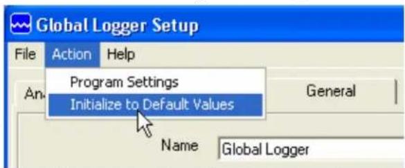
Action: The Action menu has two options, "Program Settings" and "Initialize to Default Values". Program settings will reprogram the data logger with all the setup and calibration information and works the same as the Program Settings Button at
the bottom of the screen. Initialize will restore all of the analog, digital and general setup information fields to default values. Only the setup menus are changed, the data logger must still be programmed with the new default values. A warning message will appear before this action is taken.
Help: The Help menu provides access to the on-line help files and Global Water contact information as described previously.
XIII. General Setup:
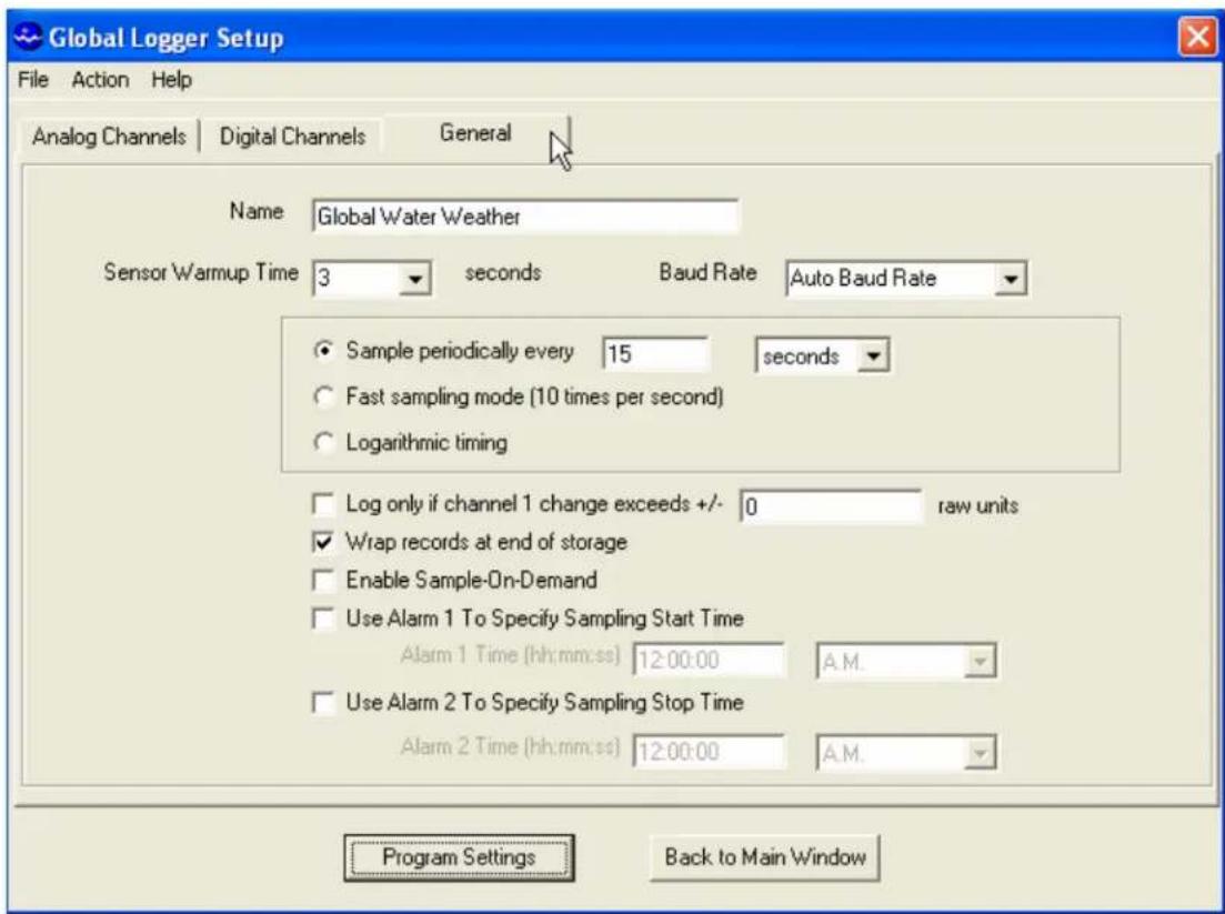
In the General Setup menu, the logger name, sensor warm-up time, logging mode, logging interval and alarm times are entered.

Global Water
800-876-1172 • globalw.com
Name: The logger is a user definable name to identify the logger. Up to 32 characters are allowed however, a continuous string of characters of more than 16 with no spaces may not be displayed correctly. Click on the field to enter information.
Sensor Warm-up Time: To conserve battery life, the sensors do not normally have power applied to them. Before taking a reading, the logger powers up the sensors for the sensor warm-up time, and then removes power from them again. The allowable times are zero (50mS) to 60 seconds. Click on the field to enter or select the time in seconds from the pull-down menu.


Baud Rate: Leave this set to Auto Baud Rate. Only change this to a fixed baud rate if planning to use this logger in a telemetry application, such as using Global Water's Global Access radio modem software. Once programmed in a fixed rate mode,

you must set the baud rate in the opening connection menu of the Global Logger II software to this speed, or the logger will not communicate.
Sample Periodically: Sampling at regular intervals is the most common recording mode. Click the Sample Periodically option, select the units from the pull-down menu and click the numerical field to enter the number of those units up to 65,535.
Fast Sampling Mode: In Fast mode, the sample rate is fixed at 10 times per second. The time stamp will not read fractions of a second so there will be 10 samples per time stamp. Click the Fast mode option to select this feature.

Global Water
800-876-1172 • globalw.com
Logarithmic Timing: Typically used in groundwater pump studies, this mode speeds up the sample rate over time. Click the “Logarithmic” option to select this mode. This a logarithmic approximation that steps up the sample rate:
a. 10 times per second for 20 seconds, 200 samples
b. 1 second interval for 100 seconds, 100 samples
c. 10 second interval for 10 minutes, 60 samples
d. 1 minute interval for 60 minutes, 60 samples
e. 10 minute interval for 10 hours, 60 samples
f. 1 hour interval for 48 hours, 48 samples
g. 1 day interval until memory s full
√ Log only if channel 1 change exceeds +/- 1638 raw units
√ Wrap records at end of storage
Log Upon Deviation: Clicking the "Log only if Channel 1 change exceeds +/-" box causes the logger to record the current reading in memory only if it exceeds the previously reading by the preset amount entered in the numeric field. This logging exception applies to channel 1 only and the deviation is measured in Raw Data units where the approximate raw data range is from 0-65535, corresponding to 0-20mA.
To find the actual number of raw data units per engineering unit, use the calibration numbers in the Analog Setup screen for channel 1 as follows: Raw Data Units per Engineering Unit = (High Raw - Low Raw) / (High EU - Low EU). For example: Assume a 15 foot water level sensor has a High EU of 15, a Low EU of zero, a High Raw of 62256 and a Low Raw of 13104. (62256-13104) / (15-0) = 3277 units/foot. Thus, if you want to log only when a reading exceeds the previous on by 0.5 feet, set the deviation to about 1638. Click the numeric field to enter the desired range.
Wrap records: If the "Wrap records at End of Storage" box is checked, Enable Sample-On-Demand Use Alarm 1 To Specify Sampling Start Time
once the memory is full, the oldest data points will be replaced with the newest. Thus, the memory block represents only the newest. If this feature is not checked, the logger will halt recording once the memory is full.
Sample-On-Demand: When this box is checked, applying a pulse to the Sample-On-Demand input will cause the logger to take a data reading and store it in memory. This feature works in all sampling modes and will not interrupt normal data recording. If the sample interval is one hour, the historical record will show data

Global Water
800-876-1172 • globalw.com
once per hour as well as the time that the sample-on-demand was triggered. This feature is used to record the time that special events occurred such as when water sampler was triggered, a door was opened, etc.
Alarm Times: Check the box associated with each alarm to enable that feature and enter the desired start or stop time. The logger will start at the next

occurrence of the Alarm 1 time and stop at the next occurrence of the Alarm 2 time after the Alarm 1 timer has expired. Either or both alarms can be enabled.
Note: The alarm start and stop cycle is a one time occurrence. Once stopped by the Alarm 2 timer, the logger will not resume logging again until the logger is reprogrammed. Reprogramming the logger with the timers enabled will restart the alarm cycle. Reprogramming the logger with the timers disabled will return the logger to a normal logging state
Use care when programming the alarm times. If left enabled, changing and reprogramming any of the setup parameters will restart the alarm timers and could cause the logger to stop recording.
XIV. Analog Setup:
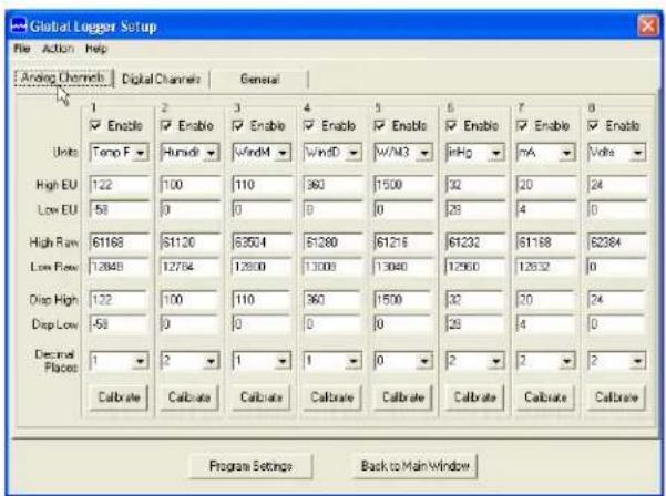
The Analog Setup screen sets the engineering units and calibration numbers for each of the analog channels, the endpoints of the bar graphs in the main screen and which of the analog channels are enabled. These channels are calibrated in the same way so a single channel will be discussed.
It is important to note here that the information stored in the data logger's memory is just the sensors output level before it is adjusted by the following calibration parameters. These parameters are used to adjust the stored data for display and storage purposes only, at the time the data is downloaded. If they are changed, the same stored data can be downloaded again and the data will be scaled differently according to the new settings.

Global Water
800-876-1172 • globalw.com
The calibration of channel one to a pH sensor is discussed in the following example where it is not practical to calibrate a sensor over its full range. The pH sensor is measures over the range of zero to 14 but is generally calibrated over a lesser range such as 4 and 10 even when it is desirable to measure beyond these limits.
Enable: If the "Enable" box at the top of a column is checked, data for that channel will be shown in the historical record and be available for export to Excel. The data for all the analog channels is always being recorded whether the channel is enabled or not.
Units: This field shows the units that will appear at the top of the data column for that channel in the historical record as well as the display of data in the main screen. Click on the field to enter the unit or select from a predefined list.


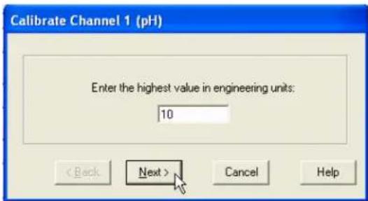
High EU: The High EU field is the engineering unit where the highest output from the sensor is achieved during the calibration process, in this case a pH of 10.
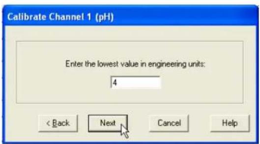
Low EU: The Low EU field is the engineering unit where the lowest output from the sensor is achieved during the calibration process, in this case a pH of 4.
High Raw: This is the raw data value as measured by the GL500 Data Logger that corresponds to the High EU value and is automatically set by the calibration process. In this case, the raw data value returned by the logger at a pH of 10.
Low Raw: This is the raw data value as measured by the logger that corresponds to the Low EU value and is automatically set by the calibration process. In this case, the raw data value returned by the logger at a pH of 4.
Disp High: This field sets the upper limit of the bar graph displayed in the main screen and provides a way of scaling the graph beyond the upper limit used to

Global Water
800-876-1172 • globalw.com
calibrate the logger. In this example, the upper calibration point was a pH of 10 but the bar graph will end at 14.
Disp Low: This field sets the lower limit of the bar graph displayed in the main screen and provides a way of scaling the graph beyond the lower limit used to calibrate the logger. In this example, the lower calibration point was a pH of 4 but the bar graph will go down to zero.
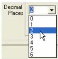
Decimal Places: From the pull-down menu, select the number of decimal places to the right of the decimal point that should appear in the historical data and in the numerical data field at the bottom of the bar graph.
Calibrate: The "Calibrate" button provides a simple 4-step process for calibrating the GL500 Data Logger to a particular sensor. Click the Calibrate button and follow the menu instructions.
Click on the High EU field and enter the high engineering unit that will be used to calibrate the sensor, not the highest reading the sensor can output. In the example of pH, enter 10 which is the highest calibration solution to be used. Click Next.
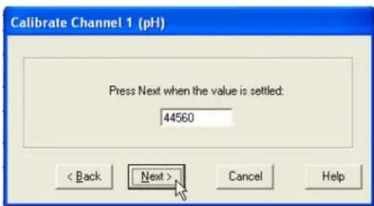
Place the sensor in the condition that will cause it to output the level corresponding to the high EU entered in the previous menu. Wait for the data reading to stabilize. Click Next.

Global Water
800-876-1172 • globalw.com
Click on the Low EU field and enter the low engineering unit that will be used to calibrate the sensor, not the lowest reading the sensor can output. In the example of pH, enter 4 which is the lowest calibration solution to be used. Click Next.
Place the sensor in the condition that will cause it to output the level corresponding to the low EU entered in the previous menu. Wait for the data reading to stabilize. Click Next to complete the calibration.

XV. Digital Setup:
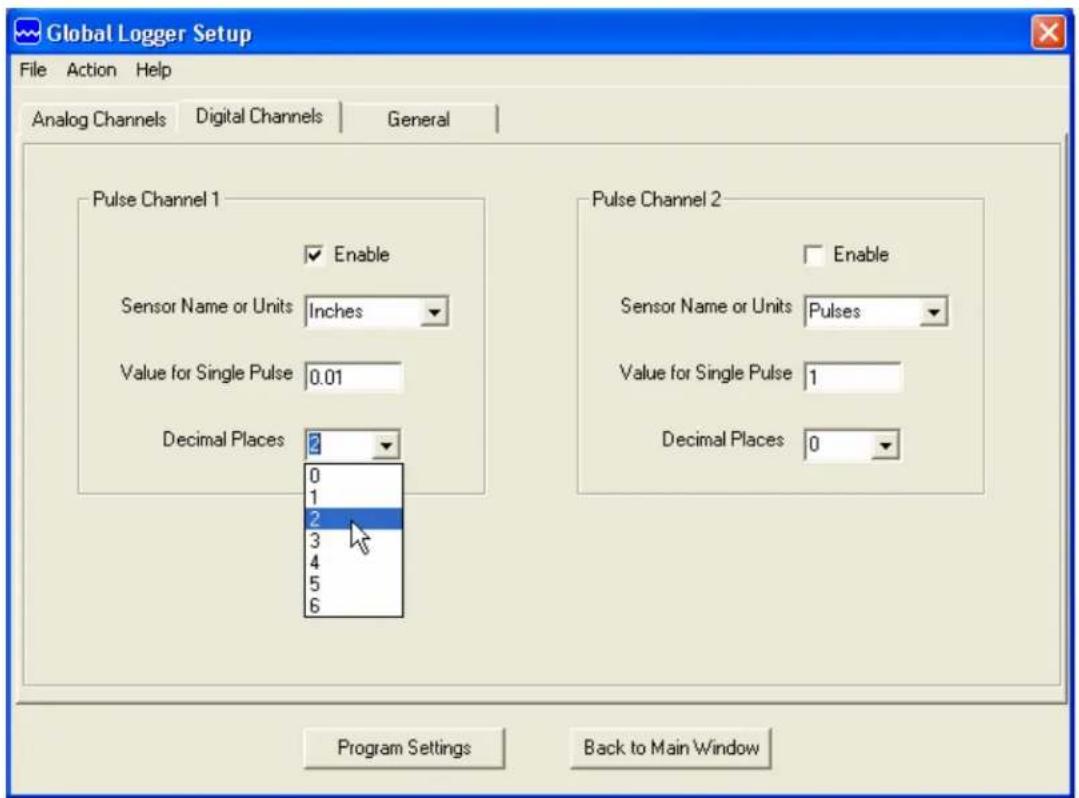
The Digital Setup screen is used for setting up the two digital pulse channels.

Global Water
800-876-1172 • globalw.com
Enable: Checking the Enable box allows the display of the data for that channel in the historical record. The pulse channels are always being monitored and the counts between sampling intervals stored whether they are enabled or not.
Units: To enter a Sensor Name or Units, click on the field and enter it or select from a list of units predefined in the pull-down menu
Value for a Single Pulse: The number of pulses is multiplied by this number to scale it to rainfall, water flow, etc. If a pulse channel is connected to a rain gauge that puts out a pulse every 1/100" of rain, click on the field and enter 0.01 to display rain
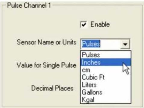
Decimal Places: This field determines how many places to the right of the decimal point the data will be displayed in the main screen and historical data record. Select the desired number of decimal places from the pull-down menu.

Global Water
800-876-1172 • globalw.com
XVI. Programming
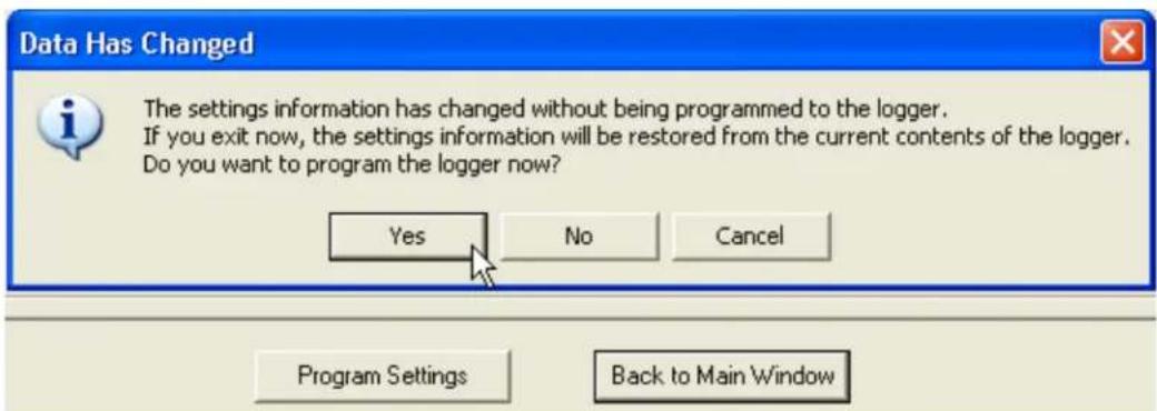
Program Settings: The Program Settings button at the bottom of the setup menus will cause all the setup and calibration information to be programmed into the data
logger. A warning will appear requiring the use to confirm the action. Click Yes to program the logger and No to cancel the operation.

Back to Main Window: The Back to Main Menu button exits back to the main
screen. If no settings have changed, Exit will occur immediately. If settings have changed but not saved yet, a message will appear that asks the user if they would like to save them now. If the settings have changed but not yet programmed into the logger, another message will

be shown asking if the logger should be reprogrammed. These layers of protection are designed to prevent the user from unintentionally changing settings or forgetting to save the configuration file. Should the settings accidentally be changed, a saved configuration file can be loaded and used to restore the original settings.

Global Water
800-876-1172 • globalw.com
XVII. Connections:
Left Hand Connector:
P2+ Pulse channel 2 +, connected to VBAT
P2 IN Pulse channel 2 pulse input
P1+ Pulse channel 1 +, connected to VBAT
P1 IN Pulse channel 2 pulse input
SMP+ Sample-On-Demand +, VBAT
SMPL Sample-On-Demand pulse input
GND Spare Ground
GND Spare Ground
VBAT Spare positive battery connection
VBAT Spare positive battery connection
GND Negative battery connection
VBAT Positive battery connection
Right Hand Connector:
V+ Switched sensor power
CH1 Analog channel 1 input
GND Sensor ground
V+ Switched sensor power
CH2 Analog channel 2 input
GND Sensor ground
V+ Switched sensor power
CH3 Analog channel 3 input
GND Sensor ground
V+ Switched sensor power
CH4 Analog channel 4 input
GND Sensor ground
V+ Switched sensor power
CH5 Analog channel 5 input
GND Sensor ground
V+ Switched sensor power
CH6 Analog channel 6 input
GND Sensor ground
V+ Switched sensor power
CH7 Analog channel 7 input
GND Sensor ground
GND Spare ground connection


flowchart
graph TD
    A["2-Wire Sensor"] --> B["Switched Power Sensor Input"]
    C["3-Wire Sensor"] --> D["Switched Power Sensor Input"]
    C --> E["Ground"]

Global Water
800-876-1172 • globalw.com
XVIII. Modem Cable Diagrams:
Use the following wiring diagrams to make a cable to connect the GL500 Data Logger to an external modem. Pre-wired cables are available from Global Water.

a. Except for an optional battery pack, there are no user-serviceable parts inside the Data Logger.
b. Global Water recommends checking the battery on a regular basis, the period depending on the type of battery used.
XX. Troubleshooting:
Issue: Logger is reading incorrectly.
a. Verify the power source is supplying enough voltage. The logger requires at least 4.2 volts to operate. If the logger is supplying power to the sensors, consult the requirements for the individual sensors.
b. Check the logger and sensor calibration and recalibrate if necessary, saving the setup file first as described in section XI.
c. Check the sensor connections and clean them according to the manufacturers recommendations.
Issue: Cannot communicate with the logger.
a. Verify that sufficient power is applied and wired correctly.
b. Check the communication cable.
c. If the connection is through the USB port, use the Device Manager to confirm that the driver is loaded and the correct virtual COM port is selected in the connection menu of the Global Logger software.
d. Check the Device Manager in your operating system and confirm that the USB COM port is not being used by another device.
e. Try reducing the baud rate in the connection screen of the Global Logger software.
f. Try switching from RS-232 to USB or USB to RS-232.

Global Water
800-876-1172 • globalw.com
XXI. Customer Support:
Call Global Water for tech support: 800-876-1172 or 916-638-3429 (many problems can be solved over the phone). Fax: 916-638-3270 or Email: globalw@globalw.com.
When calling for tech support, have the following information ready:
- Model #.
- Unit serial number.
- P.O.# the equipment was purchased on.
- Our sales number or the invoice number.
- Repair instructions and/or specific problems relating to the product.
Be prepared to describe the problem you are experiencing including specific details of the application, installation, and any additional pertinent information.
In the event that the equipment needs to be returned to the factory for any reason, please call to obtain an RMA# (Return Material Authorization). Do not return items without an RMA# displayed on the outside of the package. Include a written statement describing the problems.
Send the package with shipping prepaid to our factory address. Insure your shipment; Global Water's warranty does not cover damage incurred during transit.

Global Water
800-876-1172 • globalw.com
Declaration of CE Conformity
Global Water Instrumentation, Inc.
11390 Amalgam Way
Gold River, CA 95670 USA
FAX: 00 1 916 638 3270
Phone: 00 1 916 638 3429
declares that the Products:
Product Names: Data Loggers and Pressure Loggers
Model Numbers: GL500-7-2, GL500U-2-1, GL500S-2-1, PL200H, PL200G
conforms to the following European Council directives:
Low Voltage Directives: 2006/95/EC; Requirements covering all health and safety risks of electrical equipment operating within certain voltage ranges.
According to the following standards:
EN61010-1: 2001
Electro-Magnetic Directives: 2004/108/EC: Requirements to prevent electrical and electronic equipment from generating or being affected by electromagnetic disturbances.
According to the following standard:
EN 61326-1: 2006
Batteries Directive: 2006/66/EC; Requirements regarding the
proper handling and
accumulators.
disposal of batteries and
Global Water hereby certifies that the product stated above conforms to all directives and standards required for it to bear the CE mark.

Dale Daniel
Engineering Manager
Global Water Instrumentation, Inc.
- GL500-7-2 Data Logger
- Global Water
- 800-876-1172 • globalw.com
- Checklist:
- Inspection:
- Warranty:
- GL500 Specification:
- System Requirements:
- Desktop or Laptop computer with:
- Software Installation:
- If Windows advises that the software is not certified, click:
- "Continue Anyway".
- Direct Connection:
- Modem Connection:
- Main Screen:
- On-Line Help Files:
- Xl. Get History:
- Setup Menus:
- General Setup:
- Analog Setup:
- Digital Setup:
- Programming
- Connections:
- Left Hand Connector:
- Right Hand Connector:
- Modem Cable Diagrams:
- Troubleshooting:
- Customer Support:
- Declaration of CE Conformity
Brand : Global Water
Model : GL500
Category : Water pump