
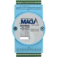
USB-5830-AE - Industrial electronic module Advantech - Free user manual and instructions
Find the device manual for free USB-5830-AE Advantech in PDF.


| Product Type | Industrial USB 3.0 Isolated I/O Module |
| Model | USB-5830-AE |
| Dimensions (W x H x D) | 120 x 120 x 40 mm (4.72 x 4.72 x 1.57 in) |
| Weight | Approx. 200 g (estimated) |
| Power Supply | 10 ~ 30 V DC (redundant inputs supported) |
| Power Consumption | Typical 240 mA @ 5 V; Max 480 mA @ 5 V |
| Operating Temperature | 0 ~ 60 °C (32 ~ 140 °F) |
| Storage Temperature | -40 ~ 70 °C (-40 ~ 158 °F) |
| Storage Humidity | 5 ~ 95% RH (non-condensing) |
| Isolated Digital Inputs | 16 channels, 10-30 V DC logic 1, 2500 Vdc isolation |
| Isolated Digital Outputs | 16 channels, sink 350 mA/ch @ 25°C, 5-40 V DC, 2500 Vdc isolation |
| USB Interface | USB 3.0 SuperSpeed, Type A (host) and Type B (hub) |
| Daisy Chaining | Built-in USB hub, up to 5 levels; external power required for >2 modules |
| Board ID Switch | 4-bit DIP switch (BID) for module identification, default 0 |
| LED Indicators | Power (on/off), Up/Error (green/red), Down (blue/hub connected) |
| Connectors | 2 x 10-pin terminal blocks (3.81 mm), 2 x 3-pin screw terminal (power) |
| Certifications | CE, FCC Class A |
| ESD Protection | 8 kV air, 6 kV contact |
| DC Surge Protection | 2 kV |
| Software Support | Windows XP/7/8/10, DAQNavi SDK, LabVIEW, Visual Studio |
| Mounting | DIN-rail mount kit included |
Frequently Asked Questions - USB-5830-AE Advantech
User questions about USB-5830-AE Advantech
0 question about this device. Answer the ones you know or ask your own.
Ask a new question about this device
Download the instructions for your Industrial electronic module in PDF format for free! Find your manual USB-5830-AE - Advantech and take your electronic device back in hand. On this page are published all the documents necessary for the use of your device. USB-5830-AE by Advantech.
USER MANUAL USB-5830-AE Advantech
natural_image
Illustration of a computer motherboard with two electronic components, one showing internal circuitry and the other a rectangular base (no text or symbols)USB-5800 Series
Industrial USB 3.0 Isolated I/O Modules
Copyright
This documentation and the software included with this product are copyrighted 2018 by Advantech Co., Ltd. All rights are reserved. Advantech Co., Ltd. reserves the right to improve the products described in this manual at any time without notice.
No part of this manual may be reproduced, copied, translated, or transmitted in any form or by any means without the prior written permission of Advantech Co., Ltd. The information provided in this manual is intended to be accurate and reliable. However, Advantech Co., Ltd. assumes no responsibility for its use, nor for any infringements of the rights of third parties that may result from its use.
Acknowledgments
Intel and Pentium are trademarks of Intel Corporation.
Microsoft Windows and MS-DOS are registered trademarks of Microsoft Corp.
All other product names or trademarks are properties of their respective owners.
Product Warranty (2 years)
Advantech warrants the original purchaser that each of its products will be free from defects in materials and workmanship for two years from the date of purchase.
This warranty does not apply to any products that have been repaired or altered by persons other than repair personnel authorized by Advantech, or products that have been subject to misuse, abuse, accident, or improper installation. Advantech assumes no liability under the terms of this warranty as a consequence of such events.
Because of Advantech's high quality-control standards and rigorous testing, most customers never need to use our repair service. If an Advantech product is defective, it will be repaired or replaced free of charge during the warranty period. For out-of-warranty repairs, customers are billed according to the cost of replacement materials, service time, and freight. Consult your dealer for more details.
If you believe that your product is defective product, follow the steps outlined below.
- Collect all information about the problem encountered. (For example, CPU speed, Advantech products used, other hardware and software used, etc.) Note anything abnormal and list any onscreen messages displayed when the problem occurs.
- Call your dealer and describe the problem. Have your manual, product, and any helpful information readily available.
- If your product is diagnosed as defective, obtain an return merchandise authorization (RMA) number from your dealer. This allows us to process your return more quickly.
- Carefully pack the defective product, a completed Repair and Replacement Order Card and a proof of purchase date (such as a photocopy of your sales receipt) into a shippable container. Products returned without a proof of purchase date are not eligible for warranty service.
- Write the RMA number visibly on the outside of the package. Then ship the package prepaid to your dealer.
Part No. 2001580010 Edition 1
Printed in China February 2018
CE
This product has passed the CE test for environmental specifications when shielded cables are used for external wiring. We recommend the use of shielded cables. This type of cable is available from Advantech. Please contact your local supplier for ordering information.
Technical Support and Assistance
- Visit the Advantech web site at http://support.advantech.com.tw/ to obtain the latest product information.
- Contact your distributor, sales representative, or Advantech's customer service center for technical support if you need additional assistance. Please have the following information ready before calling:
– Product name and serial number
– Description of your peripheral attachments
– Description of your software (operating system, version, application software, etc.)
– A complete description of the problem
– The exact wording of any error messages
Packing List
Before setting up the system, check that the items listed below are included and in good condition. If any item is missing or damaged, contact your dealer immediately.
1 x USB-5800 module
■ 2 x terminal blocks (see Appendix A - Specifications for more details)
1 x startup manual
■ 1 x USB 3.0 lockable cable (1 m)
SDK/driver DVD
Safety Precautions - Static Electricity
Follow these simple precautions to protect yourself from harm and the products from damage.
- To avoid electrical shock, always disconnect the power from the PC chassis before manual handling. Do not touch any components on the CPU card or other cards while the PC is powered on.
- Disconnect the power before implementing any configuration changes. The sudden rush of power after connecting a jumper or installing a card may damage sensitive electronic components.
Contents
Chapter 1 Introduction......1
1.1 Features ...... 2
1.2 Installation Guide .... 3
Figure 1.1 Installation flowchart .... 4
1.3 Software Overview 5
1.4 DAQnavi Device Driver Programming Roadmap 5
1.5 Accessories....6
Chapter 2 Installation....9
2.1 Unpacking Instructions.... 10
2.2 Driver Installation 11
Figure 2.1 Advantech automation software setup screen...... 11
Figure 2.2 Driver setup options....12
2.3 Hardware Installation 12
2.4 Device Setup and Configuration 13
Figure 2.3 USB-5830 device settings 13
Figure 2.4 Device settings page 14
Figure 2.5 USB-5830 device testing 14
Chapter 3 Signal Connections .....17
3.1 Overview 18
3.2 Dimensions 18
3.3 Switch and Pin Assignments.... 20
Figure 3.1 Connector and switchILocations....20
3.3.1 BID 21
3.3.2 LEDs 21
Table 3.1: Power Indicator....21
Table 3.2: Up/Error Indicator 21
Table 3.3: Down Indicator....21
3.4 Connections 22
3.4.1 Isolated DI Connection.... 22
3.4.2 Isolated DO Connection.... 22
3.4.3 Relay Output 23
3.5 Field Wiring Considerations 23
Appendix A Specifications 25
A.1 General 26
A.2 I/O Channels 26
A.3 Isolated Digital Input 26
A.4 Isolated Digital Output 27
A.5 PhotoMOS Relay Output 27
A.6 Relay Output 27
Chapter 1
Introduction
This chapter introduces USB-5800 and its typical applications.
Features
Applications
Installation Guide
Software Overview
Roadmap
Accessories
The USB-5800 series of industrial USB 3.0 isolated I/O modules are compact and equipped with a DIN-rail mount kit for easy cabinet installation. The built-in USB hub supports daisy chaining to ensure convenient expansion and reduced overall costs. Two European-type pluggable terminal blocks and LED indicator are included to assist users with system setup and maintenance. Additionally, all digital input and digital output channels feature 2,500 Vdc isolation protection.
1.1 Features
USB 3.0 SuperSpeed
■ Supports daisy chaining via a built-in USB hub
■ Digital I/O with 2,500 V dc isolation protection
■ Wide input voltage range (10 \~ 30 V DC)
■ Wide output voltage range (5 \~ 40 V DC) and high output current (350 mA/ch)
■ 1500 V dc optical isolation for photoMOS relay outputs
■ Quick-removal European-type connector
■ LED indicators for I/O status
■ Supports Windows XP/7/8/10 operating systems
The USB-5800 series modules offer the following main features:
USB 3.0 SuperSpeed
The USB-5800 series modules support USB 3.0 SuperSpeed for an accelerated response time.
Easy Maintenance
The LED indicators, rotary switch, and terminal blocks are all front-facing for easy access and wiring. The European-type pluggable terminal blocks also simplify maintenance, reducing overall service time.
Compact Size
The compact design and high density channel count increases effective space utilization, while the DIN-rail mounting kit ensures easy installation in cabinets.
Built-In USB Hub with Support for Daisy Chaining
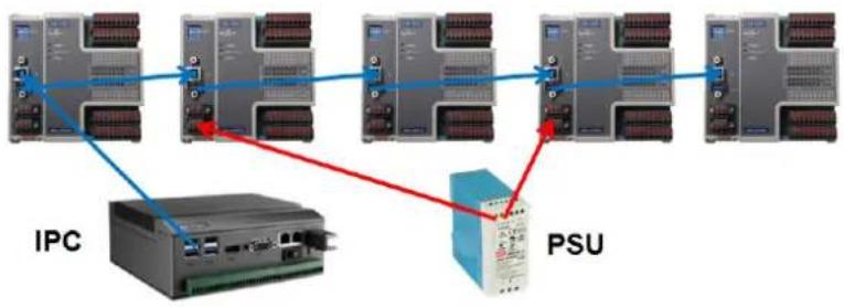
The USB-5800 module is equipped with a USB hub that supports daisy chain topologies. This feature frees up the IPC USB ports by enabling more than one USB-5800 module to be integrated into a single system.
Note! Because USB 3.0 only supplies 1A power, if more than two modules are connected via the hub, an external power unit must also be employed. Please refer to the following image.
flowchart
graph LR
    A["IPC"] --> B["Switch"]
    B --> C["PSU"]
    C --> D["Switch"]
    D --> E["PSU"]
    style A fill:#f9f,stroke:#333
    style E fill:#bbf,stroke:#333
Note! The USB host (system) can support up to five levels of hubs. If more than five levels are cascaded, the USB modules may malfunction.

Redundant Power
USB-5800 modules feature two power input terminals, an input power range of +10 to +30 VDC, and power redundancy support. For modules connected to two power input sources, if one source is inactive or interrupted, the other power source is capable of taking over immediately. The USB-5800 modules can operate as normal with only a single power source.
(If not using the USB hub function, the module can be powered via a USB 3.0port.)
BoardID Switch
The USB-5800 series modules feature a built-in DIP switch (BID) that is used to define each module's board ID. When multiple modules are integrated on the same system, the board ID switch is useful for identifying each module's device number.
After setting all the USB-5800 modules, users can identify each module in the system using their device numbers. The default Board ID value is 0.
1.2 Installation Guide
Before USB-5800 module installation, please ensure you have the following necessary components:
USB-5800 module
USB-5800 user manual
■ Advantech DAQNavi driver software (available on the accompanying DVD-ROM)
■ Personal computer or workstation with a USB interface (running the Windows 10/8/7/XP operating system)
10 \~ 30 V power supply (96PS-A40WDIN optional)
Other optional components are also available for enhanced operation:
■ DAQ Navi, LabView, and other third-party software
Once you have the necessary components and any additional accessories for enhanced operation, you can begin installing your USB-5800 module. Figure 1.1 is a flowchart that provides a broad overview of the software and hardware installation procedures.

flowchart
graph TD
    A["Install driver from DVD-ROM and turn off computer"] --> B["Install hardware and turn on computer"]
    B --> C["Use driver utility to configure hardware"]
    C --> D["Use test utility to test hardware"]
    D --> E["Read examples & driver manual"]
    E --> F["Start writing your own application"]
Figure 1.1 Installation flowchart
1.3 Software Overview
Advantech offers a wide range of DLL drivers, third-party driver support, and application software for fully exploiting the functions of your USB-5800 module:
■ Device drivers (located on the accompanying DVD-ROM)
■ Advantech DAQNavi
DAQNavi Software
Advantech's DAQNavi software includes device drivers and a software development kit (SDK), which features a comprehensive I/O function library to boost application performance. This software is provided on the accompanying DVD-ROM at no extra cost and comes with all Advantech DA&C cards. The Advantech DAQNavi software for Windows XP/7/8/10 (desktop mode) works seamlessly with development tools such as Visual Studio.NET, Visual C++, Visual Basic, and Borland Delphi.
1.4 DAQnavi Device Driver Programming Roadmap
This section provides a roadmap for building an application from scratch using Advantech's DAQNavi Device Driver with a range of development tools such as Visual Studio.NET, Visual C++, Visual Basic, Delphi, and C++ Builder. Step-by-step instructions for application development using each tool are provided in the device driver manual. A large library of example source code is also provided for your reference.
Programming Tools
Programmers can develop application programs using their preferred development tools.
Visual Studio.NET
■ Visual C++ and Visual Basic
Delphi
C++ Builder
For instructions on programming using each development tool, Advantech offers a tutorial chapter in the DAQNavi SDK manual for your reference. Please refer to the corresponding sections in the DAQNavi SDK manual to begin programming. You can also look at the example source codes provided for each programming tool. The examples can help jump start a project.
The DAQNavi SDK manual can be found on the accompanying DVD-ROM. Alternatively, if you have already installed the device drivers on your system, the DAQNavi SDK manual can be readily accessed via the Start button:
Start/Programs/Advantech Automation/DAQNavi/DAQNavi Manuals/DAQNavi SDK Manual
The example source code can be found under the corresponding installation folder/default installation path:
\Advantech\DAQNavi\Examples
For information about using other function groups or other development tools, refer to chapter titled "Using DAQnavi SDK" in the DAQnavi SDK manual, or watch the video tutorials in the Advantech Navigator.
Programming with DAQNavi Device Drivers Function Library
Advantech DAQNavi device drivers offer a comprehensive function library that can be utilized in various application programs. This function library consists of numerous
APIs that support many development tools, such as Visual Studio.NET, Visual C++, Visual Basic, Delphi and C++ Builder.
According to their functions or services, APIs can be categorized into several function groups:
■ Analog Input Function Group
■ Analog Output Function Group
■ Digital Input/Output Function Group
Counter Function Group
■ Port Function Group (direct I/O)
■ Event Function Group
For the usage and parameters of each function, refer to the chapter "Using DAQnavi SDK" in the DAQnavi SDK manual.
Troubleshooting DAQNavi Device Drivers Error
Driver functions return a status code when called to perform a certain task for an application. When a function returns a code that is not zero, it means the designated function has failed to perform. To troubleshoot the device drivers error, you can pass the error or check the error code and error description within the Error Control of each function in the DAQnavi SDK manual.
1.5 Accessories
Advantech offers accessories to support the USB-5800 module. These accessories are as follows:
Power supply unit
■ 96PS-A40WDIN 40 W, 24 V DIN-rail power supply
Chapter 2
Installation
This chapter includes a packing checklist, instructions for unpacking, and step-by-step procedures for both driver and card installation.
■ Unpacking Instructions
Driver Installation
Hardware Installation
■ Device Setup and Configuration
2.1 Unpacking Instructions
After receiving your USB-5800 module, inspect the package contents. The package should include the following items:
1 x USB-5800 module
■ 2 x Terminal blocks (see Specifications for more details)
1 x Startup manual
■ 1 x USB 3.0 lockable cable (1 m)
1 x SDK/Driver DVD
The USB-5800 module harbors contains electronic components that are vulnerable to electrostatic discharge (ESD). ESD can easily damage the integrated circuits and components if preventive measures are not carefully implemented. Before removing the module from the antistatic plastic bag, take the following precautions to prevent possible ESD damage:
■ Touch the metal part of your computer chassis with your hand to discharge any static electricity accumulated on your body. You can also use a grounding strap.
■ Make contact between the antistatic bag and ground before opening. After removing the module from the packaging, first inspect the module for any signs of external damage (loose or damaged components, etc.). If the module is visibly damaged, notify our service department or a local sales representative immediately. Avoid using a damaged module with your system.
- Avoid physical contact with materials that may hold static electricity, such as plastic, vinyl, and styrofoam.
2.2 Driver Installation
We recommend installing the driver before installing the USB-5800 module to guarantee a problem-free installation process.
The Advantech DAQNavi Device Drivers setup program for the USB-5800 module is included in the accompanying DVD-ROM. Follow the steps outlined below to install the driver software:
- Insert the accompanying DVD-ROM into the DVD-ROM drive.
- The setup program should launch automatically if the system's autoplay function is enabled. When the setup program is launched, a setup screen (see Figure 2.1) will be displayed.
Note! If the autoplay function is not enabled on your computer, use Windows Explorer or Windows Run commands to execute autorun.exe on the DVD-ROM.
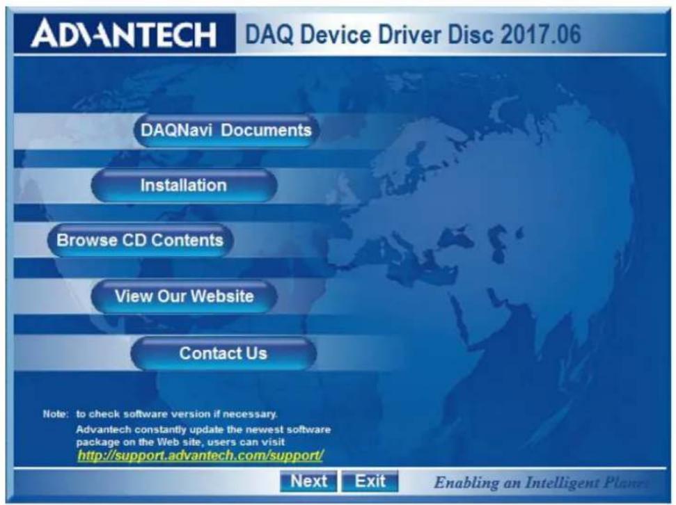
Figure 2.1 Advantech automation software setup screen
- Select the "Installation" option.
- Select the "Legacy SDK" and "Drivers" options for installation.
- Select the "Individual Drivers" option.
- Select the USB series and the specific device then follow the installation instructions step by step to complete device driver installation and setup.
- Click the back button and select the "Windows SDK" and "Drivers" options and install the Advantech Navigator.
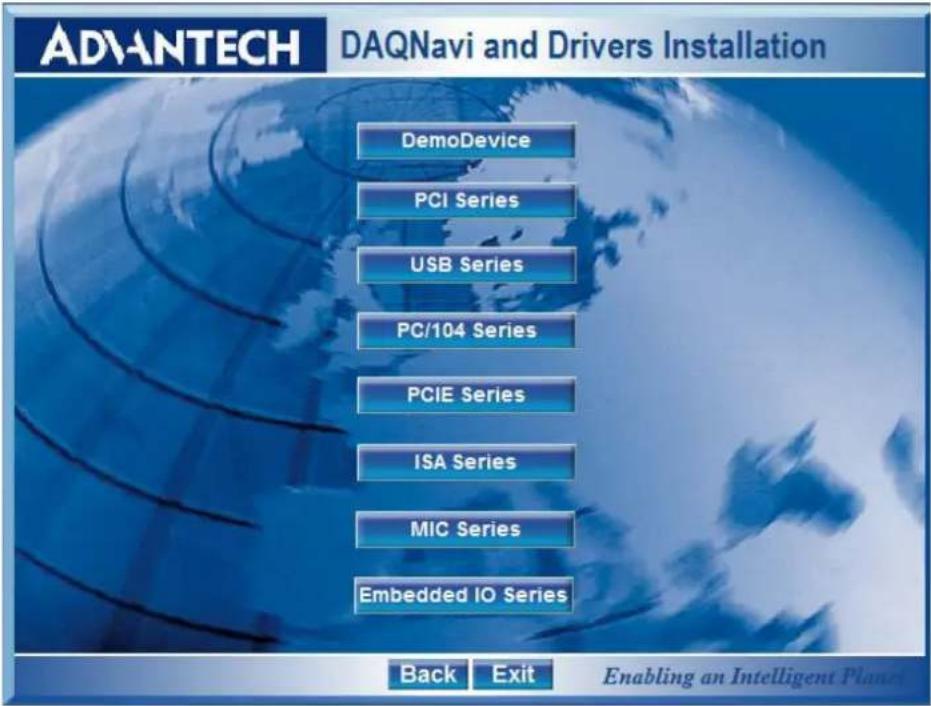
Figure 2.2 Driver setup options
For further information on driver-related issues, an online version of the DAQNavi SDK manual can be accessed using the following path:
Start/Programs/Advantech Automation/DAQNavi/DAQNavi Manuals/DAQNavi SDK Manual
2.3 Hardware Installation
Note! Ensure that the driver is installed before installing the card (refer to 2.2 Driver Installation)

After the device drivers are installed, the USB-5800 module can be installed in your computer. We recommend referring to the computer user manual or related documentation if you have any concerns. Follow the steps outlined below for module installation.
- Touch the metal part on the surface of your computer to discharge any static electricity that might be on your body.
- Plug the USB module into the selected USB port. Avoid using excessive force to prevent damage to the module.
After the module is installed, you can configure your device using the Advantech Navigator Program that is automatically installed during driver setup. A complete device installation procedure should include device setup, configuration, and testing. Information is provided in the following sections to guide users through the device setup, configuration, and testing.
2.4 Device Setup and Configuration
The Advantech Navigator program is a utility that allows users to setup, configure, and test the device, and later stores the system settings in the system registry. These settings are used when you call Advantech's device driver APIs. Consider the device details for USB-5830 shown in Figure 2.3 as an example.
Setting Up the Device
- To install an I/O device into the module, first run the Advantech Navigator program (by accessing Start/Programs/Advantech Automation/Navigator for DN4).
- Users can view the device(s) already installed on the system (if any) in the Installed Devices list box. Once the software/hardware installation is complete, you will see the USB-5830 module in the Installed Devices list.

Figure 2.3 USB-5830 device settings
Configuring the Device
- Go to the Device Setting page to configure the device. Here you can configure the USB-5830 modules' digital input/output.
![Navigator DAQNavi Devices Installed Devices DemoDevice BID#0 USB-5830,BID#0 Device Setting Profile Firmware Download Device Test Scenarios Reference Supported Devices SDK DAQNavi Tools ICOMNavi Public Tools Profile for USB-5830,BID#0 Device setting for: USB-5830 Digital Input/Output D[Inverse Ports] D[Interrupt] Port0 B47 B48 B49 B41 B42 B43 B44 B45 B46 B47 B48 B49 B50 B51 B52 B53 B54 B55 B56 B57 B58 B59 B60 B61 B62 B63 B64 B65 B66 B67 B68 B69 B70 B71 B72 B73 B74 B75 B76 B77 B78 B79 B80 B81 B82 B83 B84 B85 B86 B87 B88 B89 B90 B91 B92 B93 B94 B95 B96 B97 B98 B99 B100 Enable Channel: Port1 B47 B48 B49 B41 B42 B43 B44 B45 B46 B47 B48 B49 B50 B51 B52 B53 B54 B55 B56 B57 B58 B59 B60](/content/2026/05/942918/images/552e98cda264f062b605d6bc5ce667ae8cffca9106000cfa9e057af5d564f64e.jpg)
Figure 2.4 Device settings page
- After the module is properly installed and configured, go to the Device Test page to test the hardware using the testing utility provided.
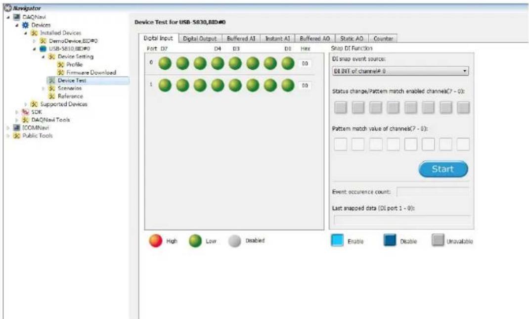
Figure 2.5 USB-5830 device testing
For more detailed information, please refer to the DAQNavi SDK manual or the user interface manual in Advantech Navigator.
Chapter 3
Signal Connections
This chapter provides useful information about connecting input and output signals to the USB-5800 module via the I/O connector.
Overview
Board ID Settings
Signal Connections
Field Wiring Considerations
3.1 Overview
Maintaining signal connections is one of the most important factors in ensuring that your application system is sending and receiving data correctly. A good signal connection can prevent unnecessary and costly damage to your PC and other hardware devices. This chapter provides useful information about how to connect input and output signals to the USB-5800 module via the I/O connector.
3.2 Dimensions
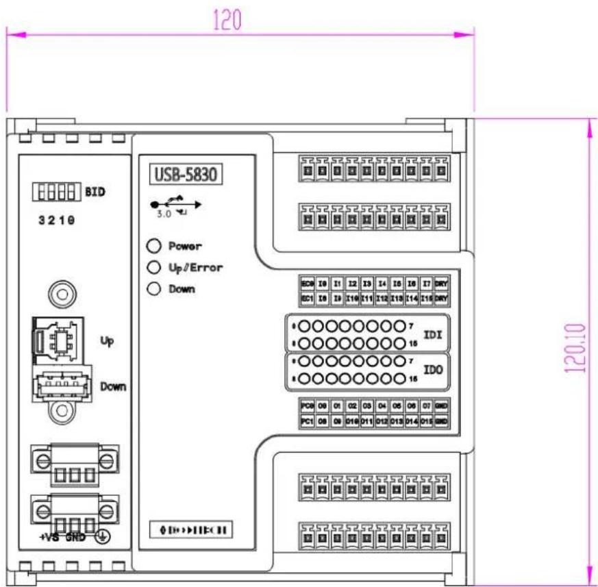
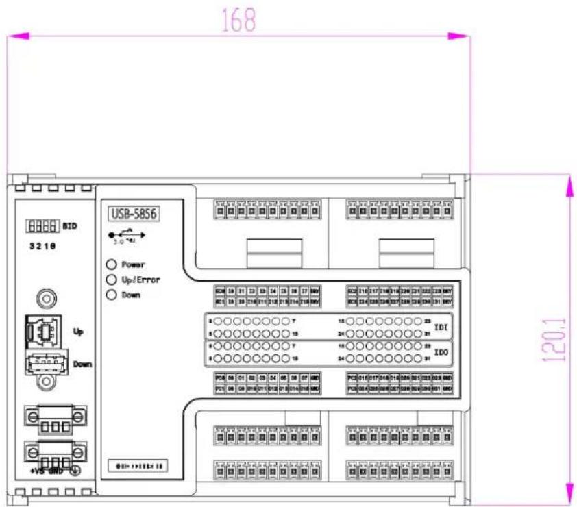
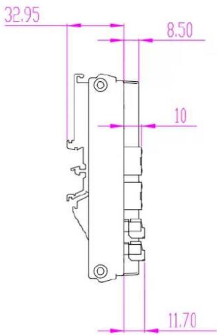
3.3 Switch and Pin Assignments
Figure 3.1 shows the jumper and switch locations on the USB-5800 module.
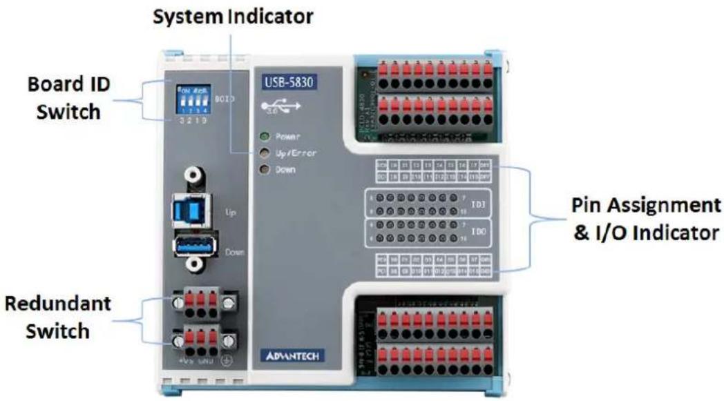
Figure 3.1 Connector and switchLocations
3.3.1 BID
The USB-5800 series modules feature a built-in DIP switch (BID), which is used to define each module's board ID. When multiple modules are installed on the same system, this board ID switch is useful for identifying each module's device number.
After setting each USB-5800, you can identify each module in the system using their different device numbers. The board ID default value is 0. Should you need to adjust the BID, refer to the table provided below.
Board ID Setting
| SW1 | Position 1 | Position 2 | Position 3 | Position 4 |
| BoardID | ID3 | ID2 | ID1 | ID0 |
| 0 | ON | ON | ON | ON |
| 1 | ON | ON | ON | OFF |
| 2 | ON | ON | OFF | ON |
| 3 | ON | ON | OFF | OFF |
| 4 | ON | OFF | ON | ON |
| 5 | ON | OFF | ON | OFF |
| 6 | ON | OFF | OFF | ON |
| 7 | ON | OFF | OFF | OFF |
| 8 | OFF | ON | ON | ON |
| 9 | OFF | ON | ON | OFF |
| 10 | OFF | ON | OFF | ON |
| 11 | OFF | ON | OFF | OFF |
| 12 | OFF | OFF | ON | ON |
| 13 | OFF | OFF | ON | OFF |
| 14 | OFF | OFF | OFF | ON |
| 15 | OFF | OFF | OFF | OFF |
Default Setting is 0
3.3.2 LEDs
Table 3.1: Power Indicator
| Indicator State Description |
| Off The system is not on/power is off |
| On The system is on/power is on |
Table 3.2: Up/Error Indicator
| Indicator State Condition |
| Green On The device is connected to the system |
| Red On The device is not connected to the system |
Table 3.3: Down Indicator
| Indicator State Description |
| Off The USB hub is not connected to any device |
| Blue On The USB hub is connected to a device |
3.4 Connections
3.4.1 Isolated DI Connection
All isolated digital input channels accept voltages ranging from 10 to 30 V.
Additionally, every eight input channels share one external common pin (channels 0 \~ 7 use EC0, channels 8 \~ 15 use EC1). The figure below shows how to connect an external input source to the module's isolated inputs.

3.4.2 Isolated DO Connection
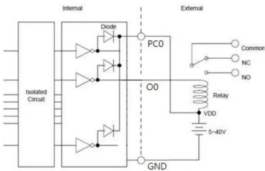
If an external voltage source (5 \~ 40 V) is connected to each isolated output channel (On) and its isolated digital output is turned on (350 mA max./ch), the module will sink current from the external voltage source. Isolated DO modules provide EGND pins for IDO connection. The following figure shows how to connect an external output load to the module's isolated outputs.
3.4.3 Relay Output
The figure below illustrates the structures and connections of the relay outputs.

3.5 Field Wiring Considerations
When using USB-5800 modules for data collection in an outdoor environment, any noises from the environment can significantly affect the accuracy. The following measures are helpful for reducing possible interference when running signal wires between signal sources and the USB-5800 module.
Signal cables must be kept away from strong electromagnetic sources, such as power lines, large electric motors, circuit breakers, or welding machines, because they may cause strong electromagnetic interference. Keep analog signal cables away from video monitors because they can significantly affect data acquisition systems.
If the cable travels through an area with significant electromagnetic interference, users should use individually shielded, twisted-pair wires as the analog input cable. This type of cable features signal wires twisted together and shielded with a metal mesh. The metal mesh should only be connected to one point at the signal source ground.
- Avoid running the signal cables through any conduit that may have power lines running through it.
If you must place your signal cable parallel to a power line that has a high voltage or high current running through it, try to keep a safe distance between them. Alternatively, you can place the signal cable at a right angle to the power line to minimize undesirable effects.
Appendix A
Specifications
A.1 General
| Item Description | |
| Connectors | 10-pin terminal block, 3.81 mm *N |
| 3-pin screw terminal block, 3.81 mm * 2 (power) | |
| USB 3.0 type A (to PC) | |
| USB 3.0 type B (hub) | |
| Dimensions | 120 x 120 x 40 mm (4.72 x 4.72 x 1.57 in) for USB-5830/5850/5860 |
| 168 x 120 x 40 mm for (6.61 x 4.72 x 1.57) USB-5855/5856/5862 | |
| Operating Temperature | 0 ~ 60 °C (32 ~ 140 °F) |
| Storage Temperature | -40 ~ 70 °C (-40 ~ 158 °F) |
| Storage Humidity | 5 ~ 95% RH (non-condensing) |
| Power Supply | 10 ~ 30 V DC |
| Power Consumption | Typical 240mA @5 V |
| Max. 480mA @ 5V for USB-5830/5850/5860 | |
| Max. 720mA @ 5V for USB-5855/5856/5862 | |
| Certification CE, FCC Class A | |
| ESD Protection 8KV (air), 6KV (contact) | |
| DC Surge Protection 2KV | |
*N
| USB-5830 | USB-5850 | USB-5855 | USB-5856 | USB-5860 | USB-5862 | |
| N | 4 | 4 | 8 | 8 | 3 | 6 |
A.2 I/O Channels
| Item | USB-5830 | USB-5850 | USB-5855 | USB-5856 | USB-5860 | USB-5862 |
| Isolated digital input channels | 16 16 | 32 32 | 8 | 16 | ||
| Isolated digital output channels | 16 | - | - | 32 | - | - |
| PhotoMOS relay output channels | - | 8 | 16 | - | - | - |
| Relay output channels | - | - | - | - | 8 | 16 |
A.3 Isolated Digital Input
| Item Description | |
| Input voltage | Logic 0: 3 V max. |
| Logic 1: 10 V min. (30 V max.) | |
| Isolation protection | 2,500 V_DC |
A.4 Isolated Digital Output
| Item Description | |
| Load voltage 5 ~ 40 V DC | |
| Load current | 350mA/ch (sink)@25 °C |
| 250mA/ch (sink) @60 °C | |
| Isolation protection | 2,500 V_DC |
| Opto-isolator response time | 100 us |
A.5 PhotoMOS Relay Output
| Item Description |
| Relay type PhotoMOS SPST (Form A) |
| Load voltage 60 V (AC peak or DC) |
| Load current 1.2A |
| Peak load current 4A @100 ms (1 pulse) |
| Isolation protection 1,500 V DC |
| Turn-on time 1 ms typical |
| Turn-off time 0.6 ms typical |
A.6 Relay Output
| Item Description | |
| Relay type Form A | |
| Contact rating (resistive) 2A@250 VAC,2A@30 VDC | |
| Max. switching power 500 VAC, 60W | |
| Max. switching voltage 270 V AC, 125 VDC | |
| Resistance 30 mΩ max. | |
| Operating time Max. 10 ms | |
| Releasing time Max. 5ms | |
| Life expectancy Mechanical 2 × 10^7 ops. at no load. | |
| Electrical 3 × 10^4 ops. @2A/250 VAC |
www.advantech.com
Please verify specifications before quoting. This guide is intended for reference purposes only.
All product specifications are subject to change without notice.
No part of this publication may be reproduced in any form or by any means, such as electronically, by photocopying, recording or otherwise, without prior written permission from the publisher.
All brand and product names are trademarks or registered trademarks of their respective companies.
© Advantech Co., Ltd. 2017

- USB-5800 Series
- Copyright
- Acknowledgments
- Product Warranty (2 years)
- CE
- Technical Support and Assistance
- Packing List
- Safety Precautions - Static Electricity
- Contents
- Chapter 1 Introduction......1
- Chapter 2 Installation....9
- Chapter 3 Signal Connections .....17
- Appendix A Specifications 25
- Chapter 1
- Introduction
- Features
- USB 3.0 SuperSpeed
- Easy Maintenance
- Compact Size
- Built-In USB Hub with Support for Daisy Chaining
- Redundant Power
- BoardID Switch
- Installation Guide
- Software Overview
- DAQNavi Software
- DAQnavi Device Driver Programming Roadmap
- Programming Tools
- Start/Programs/Advantech Automation/DAQNavi/DAQNavi Manuals/DAQNavi SDK Manual
- \Advantech\DAQNavi\Examples
- Programming with DAQNavi Device Drivers Function Library
- Troubleshooting DAQNavi Device Drivers Error
- Accessories
- Power supply unit
- Chapter 2
- Installation
- Unpacking Instructions
- Driver Installation
- Hardware Installation
- Device Setup and Configuration
- Setting Up the Device
- Configuring the Device
- Chapter 3
- Signal Connections
- Overview
- Dimensions
- Switch and Pin Assignments
- BID
- LEDs
- Connections
- Isolated DI Connection
- Isolated DO Connection
- Relay Output
- Field Wiring Considerations
- Appendix A
- A.1 General
- A.2 I/O Channels
- A.3 Isolated Digital Input
- A.4 Isolated Digital Output
- A.5 PhotoMOS Relay Output
- A.6 Relay Output
- www.advantech.com
Brand : Advantech
Model : USB-5830-AE
Category : Industrial electronic module