
VSNC - Solenoid Valve Festo - Free user manual and instructions
Find the device manual for free VSNC Festo in PDF.


User questions about VSNC Festo
0 question about this device. Answer the ones you know or ask your own.
Ask a new question about this device
Download the instructions for your Solenoid Valve in PDF format for free! Find your manual VSNC - Festo and take your electronic device back in hand. On this page are published all the documents necessary for the use of your device. VSNC by Festo.
USER MANUAL VSNC Festo
natural_image
Technical illustration of a mechanical assembly with gears and bolts (no text or symbols)FESTO
Festo SE & Co. KG
Ruiter Straße 82
73734 Esslingen
Germany
+49 711 347-0
www.festo.com
Assembly instructions
8149698
2021-01
[8149700]

Translation of the original instructions
© 2021 all rights reserved to Festo SE & Co. KG
1 Applicable Documents
i
All available documents for the product → www.festo.com/sp.
2 Safety
2.1 Safety instructions
– Before working on the product, switch off the power supply and secure it against being switched on again.
2.2 Intended use
The solenoid valve is intended for mounting on a drive with a NAMUR plug pattern in accordance with VDI/VDE 3845 Sheet 1:2010-09.
3 Additional information
- Accessories www.festo.com/catalogue.
4 Product overview
4.1 Included in scope of delivery
VSNC-F...-M52-...-P2
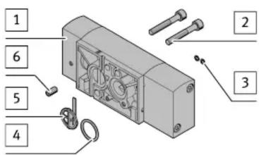
1 Basic valve (1x)
single solenoid,
5/2 or 3/2
2 Screw (2x)
3 0-ring 3x1 (2x)
4 O-ring 16x2 (1x)
5 Sheet metal seal (1x)
6 Coding pin (1x)
Fig. 1 VSNC-F...-M52-...-P2
VSNC-F...-B52-...-P2

1 Basic valve (1x)
double solenoid 5/2
2 Screw (2x)
3 O-ring 3x1 (4x)
4 O-ring 16x2 (2x)
6 Coding pin (1x)
Fig. 2 VSNC-F...-B52-...-P2
VSNC-F...-P53...-...-P2

1 Basic valve (1x)
double solenoid 5/3
2 Screw (2x)
3 0-ring 3x1 (4x)
4 O-ring 16x2 (2x)
6 Coding pin (1x)
Fig. 3 VSNC-F...-P53...-...-P2
4.2 Not in scope of delivery
Pilot valve

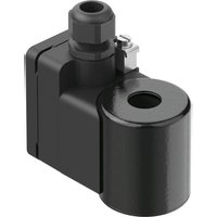
7 Pilot valve (1x)
MGXDH-3/2-1.2-...-EX,
MGXIAH-3/2-0.8-24DC-EX
8 Screw (2x)
M4x35
Fig. 4
Connector

9 Connector (1x)
VABF-B14-P1-G18,
VABF-B14-P1-N18
10 Screw (2x)
M4x16
Fig. 5
5 Preassembly

Fig. 6
- Press O-rings 3 into the recesses [A].
5.1 With electrical control
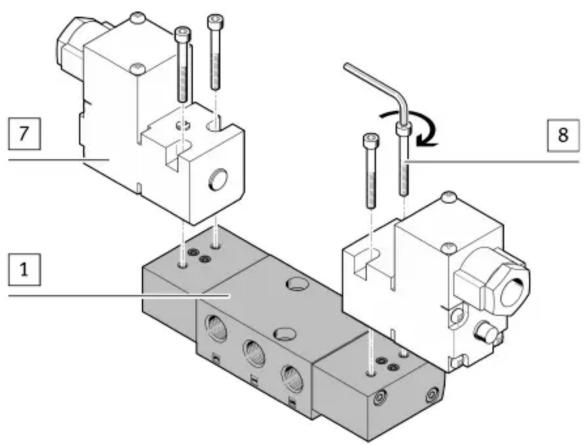
Fig. 7
1. Place pilot valves 7 on the basic valve 1.
2. Tighten screws 8. Tightening torque: 1.4 Nm ± 10%
5.2 With pneumatic control

Fig. 8
1. Place the connectors 9 on the basic valve 1.
2. Tighten screws 10. Tightening torque: 1.4 Nm ± 10%
6 Assembly
Requirement for outdoor application:
Protection against sealing of exhaust ducts 3/5 e.g. by frozen condensate or nesting insects.
- Take on-site environmental conditions into account.
- Take suitable protective measures. For example:
– Use exhaust protection VABD-D3-SN-G14. - Duct exhaust air.
i
The orientation of the basic valve 1 depends on the position of the coding pin 6. The position of the coding pin 6 determines the direction of movement at the drive.
6.1 VSNC-F...-M52-...-P2

Fig. 9 Valve function 5/2

Fig. 10 Valve function 3/2
- Press O-ring 4 into the recess [C].
- Orient the sheet metal seal 5 in accordance with the desired valve function.
- Press sheet metal seal 5 into the recess [D].
6.2 VSNC-F...-B52/-P53...-...-P2

Fig. 11
- Press O-rings 4 into the recesses [B].
6.3 Mounting on the drive

Fig. 12
- Position coding pin 6 on the thread [E]/[F] in accordance with the desired direction of movement.
- Screw coding pin 6 into the thread [E]/[F] to the stop.
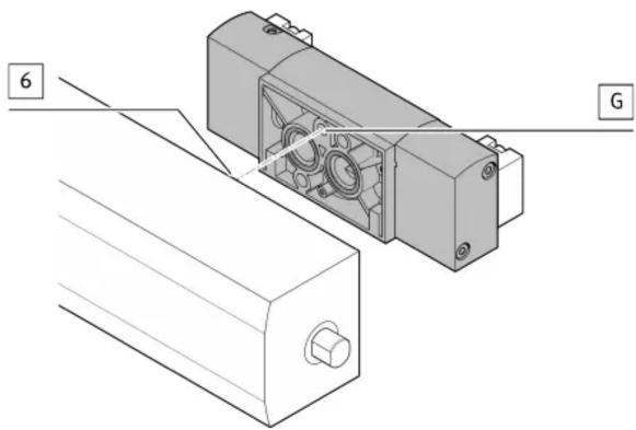
Fig. 13
- Place coding recess [G] on the coding pin 6.

natural_image
Technical line drawing of a mechanical assembly with a lever and adjustment knob (no text or symbols)Fig. 14
- Tighten screws 2. Tightening torque: 3.5 Nm ± 20%
7 Circuit diagrams
VSNC-F...-...-P2
 |
Tab. 1

Brand : Festo
Model : VSNC
Category : Solenoid Valve