
PTP 700 - Router Cambium Networks - Free user manual and instructions
Find the device manual for free PTP 700 Cambium Networks in PDF.


| Product Type | Point-to-Point Wireless Ethernet Bridge |
| Brand | Cambium Networks |
| Model | PTP 700 Series (PTP 45700 / PTP 78700) |
| Frequency Bands | 4.4–5.875 GHz (PTP 45700), 7.125–8.5 GHz (PTP 78700) |
| Data Capacity | Up to 503 Mbps aggregate (PTP 78700, 45 MHz channel) |
| Range | Up to 250 km (PTP topology), up to 100 km (HCMP topology) |
| Duplexing | Time Division Duplex (TDD), symmetric or asymmetric |
| Modulation | OFDM with adaptive modulation (BPSK to 256QAM), MIMO-A / MIMO-B |
| Channel Bandwidth | 5, 10, 15, 20, 30, 40, 45 MHz (PTP); 20 or 40 MHz (HCMP) |
| Ethernet Interfaces | Main PSU (PoE), SFP (copper/fiber), Aux (with PoE out) |
| Power Supply | AC+DC Enhanced Power Injector 56V (input 100–240V AC) |
| Outdoor Unit Dimensions (approx) | 30 x 30 x 8 cm (varies by variant) |
| Outdoor Unit Weight (approx) | 3–5 kg depending on variant |
| Security | AES 128/256 encryption, FIPS 140-3 Level 2, TLS/PSK |
| Management | Web GUI (HTTP/HTTPS), SNMP v1/2c/v3, cnMaestro, syslog, RADIUS |
| Synchronization | TDD synchronization via PTP-SYNC or direct connection, GPS optional |
| Protected Links | Hot Standby (1+1) and 2+0 link aggregation |
| Environmental Protection | IP66/67 (ODU), lightning protection with LPU, grounding kit |
| Maintenance | No user-serviceable parts; clean with dry cloth; firmware upgrade via web |
| Spare Parts & Repair | PSU, LPU, drop cables, SFP modules, antennas; RMA via Cambium support |
Frequently Asked Questions - PTP 700 Cambium Networks
User questions about PTP 700 Cambium Networks
0 question about this device. Answer the ones you know or ask your own.
Ask a new question about this device
Download the instructions for your Router in PDF format for free! Find your manual PTP 700 - Cambium Networks and take your electronic device back in hand. On this page are published all the documents necessary for the use of your device. PTP 700 by Cambium Networks.
USER MANUAL PTP 700 Cambium Networks
natural_image
Person in camouflage uniform holding a tablet, outdoors with blurred greenery background (no text or symbols visible)
Cambium Networks™

natural_image
Green military radar or missile launcher device against a clear blue sky (no visible text or symbols)
natural_image
Silhouette of a coastal area with multiple communication towers against a twilight sky with scattered clouds (no text or symbols visible)
natural_image
Outdoor megaphone mounted on a pole against a blue sky with clouds and trees (no visible text or symbols)USER GUIDE
PTP 700 Series
System Release 700-04-20

natural_image
Two military scenes: top shows a soldier operating equipment near a vehicle; bottom shows a soldier using a handheld device in a grassy field (no visible text or symbols)
natural_image
Silhouettes of military personnel on armored vehicles at sunset, no visible text or symbolsReservation of Rights
Cambium reserves the right to make changes to any products described herein to improve reliability, function, or design, and reserves the right to revise this document and to make changes from time to time in content hereof with no obligation to notify any person of revisions or changes. Cambium recommends reviewing the Cambium Networks website for the latest changes and updates to products. Cambium does not assume any liability arising out of the application or use of any product, software, or circuit described herein; neither does it convey license under its patent rights or the rights of others. It is possible that this publication may contain references to, or information about Cambium products (machines and programs), programming, or services that are not announced in your country. Such references or information must not be construed to mean that Cambium intends to announce such Cambium products, programming, or services in your country.
Copyrights
This document, Cambium products, and 3 rd Party software products described in this document may include or describe copyrighted Cambium and other 3 rd Party supplied computer programs stored in semiconductor memories or other media. Laws in the United States and other countries preserve for Cambium, its licensors, and other 3 rd Party supplied software certain exclusive rights for copyrighted material, including the exclusive right to copy, reproduce in any form, distribute and make derivative works of the copyrighted material. Accordingly, any copyrighted material of Cambium, its licensors, or the 3 rd Party software supplied material contained in the Cambium products described in this document may not be copied, reproduced, reverse engineered, distributed, merged or modified in any manner without the express written permission of Cambium. Furthermore, the purchase of Cambium products shall not be deemed to grant either directly or by implication, estoppel, or otherwise, any license under the copyrights, patents or patent applications of Cambium or other 3rd Party supplied software, except for the normal non-exclusive, royalty free license to use that arises by operation of law in the sale of a product.
Restrictions
Software and documentation are copyrighted materials. Making unauthorized copies is prohibited by law. No part of the software or documentation may be reproduced, transmitted, transcribed, stored in a retrieval system, or translated into any language or computer language, in any form or by any means, without prior written permission of Cambium.
License Agreements
The software described in this document is the property of Cambium and its licensors. It is furnished by express license agreement only and may be used only in accordance with the terms of such an agreement.
© 2024 Cambium Networks Limited. All Rights Reserved.
About This User Guide....1
Contacting Cambium Networks....1
Purpose ....1
Cross references....2
Feedback 2
Important regulatory information....3
Complying with rules for the country of operation....3
Radar avoidance....3
Application firmware....3
External antennas....3
Ethernet networking skills....4
Lightning protection 4
Training 4
Problems and warranty ....5
Reporting problems ....5
Repair and service....5
Hardware warranty....5
Security advice 6
Precautionary statements....7
Warning....7
Attention....7
Note 7
Caring for the environment....8
In EU countries 8
In non-EU countries 8
Chapter 1: Product description....1-1
Overview of the PTP 700 Series....1-2
Purpose 1-2
Key features....1-2
Frequency bands....1-4
Typical bridge deployment 1-4
Hardware overview....1-5
Protected links....1-6
Wireless topology....1-8
PTP topology 1-8
HCMP topology....1-8
Hot Standby (1+1) link protection.... 1-9
2+0 link protection 1-11
Wireless interface 1-12
Orthogonal Frequency Division Multiplexing (OFDM)....1-12
OFDM and channel bandwidth....1-12
Adaptive modulation....1-13
MIMO 1-14
Spatial diversity....1-15
Time division duplexing in PTP wireless topology 1-16
Time division duplexing in Hot Standby (1+1) link protection....1-18
Time division duplexing in HCMP wireless topology....1-19
TDD synchronization 1-21
Wireless resource allocation....1-24
License keys and regulatory bands....1-24
Spectrum management 1-25
RF channel selection....1-25
Fixed frequency 1-26
Dynamic spectrum optimization....1-26
Slave scan in HCMP 1-28
Radar avoidance....1-29
Link mode optimization....1-30
Link symmetry 1-31
Dynamic time slot allocation in HCMP 1-35
Automatic alignment....1-36
Beam Steering ODU 1-36
TD-90 antenna positioner 1-37
Using the Beam Steering ODU with TD-90....1-38
Wireless encryption 1-39
Access method....1-39
Encryption options 1-39
TLS RSA 1-40
TLS PSK 128-bit and TLS PSK 256-bit....1-41
Over the air rekeying 1-42
Designing PTP networks 1-43
Ethernet bridging....1-45
Ethernet ports....1-45
Data and management services 1-45
Ethernet switching....1-46
Data Service 1-47
Out-of-Band Management Service....1-49
Link protection....1-51
TD-90 Service....1-52
Protocol model....1-52
Synchronous Ethernet....1-53
IEEE 1588-2008 Transparent Clock....1-54
TDM bridging 1-55
System management....1-56
Management agent....1-56
Network management....1-57
IPv6 1-59
cnMaestro device agent....1-60
Critical security parameters 1-61
Configuration templates....1-61
Web server....1-63
Web management authentication 1-65
SNMP 1-69
Standalone management of TD-90....1-70
Integrated management of TD-90 1-70
System Clock 1-72
SNMPv3 security 1-72
System logging (syslog)....1-75
Domain Name Service (DNS)....1-75
Instant messaging 1-76
AES license 1-76
Firmware upgrade....1-77
Capability upgrades 1-78
Full capability trial period 1-79
Recovery mode 1-80
Upgrade from earlier releases....1-81
PTP topology 1-81
HCMP topology 1-81
FIPS 140-3 mode....1-82
FIPS 140-3 approved mode....1-82
Exiting from the FIPS operational state....1-84
Reverting to the standard (non-FIPS) mode....1-85
Chapter 2: System hardware....2-1
Outdoor unit (ODU) 2-2
ODU description 2-2
PTP 45700 Connectorized+Integrated ODU....2-3
PTP 45700 Connectorized ODU 2-6
PTP 45700 Beam Steering ODU 2-8
PTP 78700 Integrated ODU 2-9
PTP 78700 Connectorized ODU....2-10
ODU capability upgrades 2-12
ODU accessories....2-13
ODU cables 2-13
ODU mounting brackets 2-13
ODU interfaces 2-15
ODU mechanical specifications....2-18
Power supply units (PSU) 2-20
AC+DC Enhanced Power Injector 56V....2-20
Antennas and antenna cabling 2-24
Antenna requirements....2-24
RF cable and connectors....2-24
Antenna accessories 2-24
RF Combiner Kit 2-25
Ethernet cabling 2-27
Ethernet standards and cable lengths....2-27
Outdoor copper Cat5e Ethernet cable 2-28
Cable grounding kit 2-29
Lightning protection unit (LPU) and grounding kit 2-30
LPU for GPS drop cables 2-31
RJ45 connectors and spare glands 2-32
Cable hoisting grip....2-33
Indoor Cat5e cable....2-33
SFP module kits 2-33
Optical cable and connectors....2-35
PTP-SYNC unit 2-37
PTP-SYNC unit description....2-37
PTP-SYNC part numbers 2-38
PTP-SYNC unit interfaces....2-39
PTP-SYNC specifications....2-40
GPS receivers 2-43
Trimble Acutime™ GG GPS receiver for PTP-SYNC 2-43
Chapter 3: System planning ....3-1
Typical deployment 3-2
ODU with POE interface to PSU 3-2
SFP and Aux Ethernet interfaces 3-5
GPS receiver interfaces 3-8
Site planning 3-10
Grounding and lightning protection 3-10
Lightning protection zones 3-10
Site grounding system....3-11
ODU and external antenna location 3-11
ODU ambient temperature limits 3-12
ODU wind loading 3-13
Hazardous locations....3-14
PSU DC power supply 3-14
PSU AC power supply 3-14
PSU location 3-14
PTP-SYNC location 3-14
GPS receiver location....3-14
Drop cable grounding points....3-15
LPU location 3-16
Multiple LPUs 3-16
Hot Standby 3-19
Radio spectrum planning....3-20
General wireless specifications 3-20
Regulatory limits....3-21
Conforming to the limits....3-22
Available spectrum....3-22
Channel bandwidth....3-22
Frequency selection 3-22
Link planning 3-24
LINKPlanner 3-24
Range and obstacles....3-24
LINKPlanner for synchronized networks 3-25
Path loss....3-25
Adaptive modulation 3-25
Calculating data rate capacity....3-25
Planning for connectorized units....3-30
When to install connectorized units....3-30
Choosing external antennas....3-30
Protected links with shared antenna 3-31
Link configurations for protection and spatial diversity 3-32
Unprotected links 3-32
Protected links....3-33
End configurations for spatial diversity....3-34
Configuration options for TDD synchronization....3-36
Using PTP-SYNC with PTP 45700 3-36
Using a direct connection between ODUs....3-39
TDD burst durations in PTP topology 3-40
TDD frame durations....3-45
TDD frame design for standalone synchronization....3-46
TDD frame design for network-wide synchronization 3-46
Data network planning....3-47
Ethernet bridging 3-47
Layer two control protocols....3-47
Ethernet port allocation....3-48
VLAN membership....3-53
Priority for management traffic 3-53
IP interface for NMS 3-54
IP interface for integrated TD-90 management....3-54
Quality of service for bridged Ethernet traffic....3-54
Integrated management of TD-90 3-55
"Daisy-chaining" PTP 700 links....3-55
Green Ethernet switches 3-56
Network management planning....3-57
Planning for cnMaestro 3-57
Standard templates in the simplified web interface 3-57
Custom templates in the simplified web interface 3-60
Planning for SNMP operation....3-61
SNMP Configuration Mode....3-62
Planning for Domain Name Service (DNS) 3-67
Hot Standby links 3-67
Security planning 3-68
License key digital signature....3-68
Planning for SNTP operation 3-69
Using the Security Wizard 3-69
Planning for wireless encryption....3-70
Planning for HTTPS/TLS operation 3-72
Planning for protocols and ports....3-73
Planning for SNMPv3 operation....3-73
Planning for RADIUS operation 3-77
Planning for Single Sign-On (SSO) Operation 3-78
Internally-generated random keys....3-79
Integrated management of TD-90 3-79
Planning for FIPS 140-3 operation.... 3-80
System threshold, output power and link loss....3-82
Connectorized+Integrated ODUs....3-83
Connectorized and Beam Steering ODUs....3-94
Data throughput capacity tables....3-112
Data capacity in PTP topology 3-112
Time slots per frame in PTP topology with synchronization.... 3-169
Frame duration in HCMP topology with standard configuration....3-172
Frame duration in HCMP topology with expert configuration 3-180
Capacity per time slot 3-181
Chapter 4: Regulatory information....4-1
Compliance with safety standards 4-2
Electrical safety compliance 4-2
Electromagnetic compatibility (EMC) compliance 4-2
Human exposure to radio frequency energy 4-2
Compliance with radio regulations 4-5
Chapter 5: Installation....5-1
Safety 5-2
Power lines 5-2
Working at heights 5-2
PSU 5-2
Grounding and protective earth 5-2
AC supply 5-2
DC supply 5-2
Powering down before servicing 5-3
Primary disconnect device 5-3
External cables 5-3
Drop cable tester....5-3
Grounding PTP-SYNC 5-3
RF exposure near the antenna 5-3
Minimum separation distances....5-3
Grounding and lightning protection requirements.... 5-3
Grounding cable installation methods 5-4
Siting ODUs and antennas 5-4
Thermal Safety 5-4
ODU variants and mounting bracket options 5-5
Installing the ODU and top LPU 5-6
Attach ground cables to the ODU 5-6
Mount the ODU on the mast 5-6
Mount the top LPU 5-11
Interconnect and ground the ODU and top LPU....5-12
Install external antennas....5-15
Install RF Combiners....5-17
Assemble and mount the RF Combiners....5-17
Interconnect the RF Combiners, ODUs and antennas....5-18
Installing the copper Cat5e Ethernet interface 5-19
Install the ODU to top LPU drop cable 5-19
Install the main drop cable 5-22
Install the bottom LPU to PSU drop cable....5-24
Test resistance in the drop cable 5-26
Installing the PSU 5-27
Installing the AC+DC Enhanced Power Injector 56V....5-27
Installing a PTP-SYNC unit 5-29
Mounting the PTP-SYNC unit 5-29
Connecting up the PTP-SYNC unit 5-30
Powering up the PTP-SYNC installation....5-32
Installing the Trimble Accutime GPS receiver 5-33
Mounting the GPS receiver 5-33
Preparing the GPS drop cable....5-33
Assembling an RJ45 plug and housing for GPS....5-34
Assembling a 12 way circular connector ....5-36
Connecting the GPS drop cable 5-40
Top grounding point for GPS adapter cable 5-40
Installing and connecting the GPS LPU 5-42
Installing an SFP Ethernet interface 5-43
Fitting the long cable gland 5-45
Inserting the SFP module....5-46
Connecting the cable....5-48
Fitting the gland 5-49
Removing the cable and SFP module 5-51
Installing an Aux Ethernet interface 5-52
Supplemental installation information 5-53
Stripping drop cable 5-53
Creating a drop cable grounding point 5-54
Weatherproofing an N type connector....5-57
Replacing PSU fuses....5-60
Chapter 6: Configuration and alignment....6-1
Preparing for configuration and alignment.... 6-2
Safety precautions 6-2
Regulatory compliance 6-2
Selecting configuration options....6-2
Generating license keys 6-2
Connecting to the unit....6-4
Configuring the management PC....6-4
Connecting to the PC and powering up 6-5
Using the web interface....6-6
Creating a user account....6-6
Logging into the web interface....6-7
Using the menu options for the standard web interface 6-8
Using the menu options for the simplified web interface....6-11
Standard Installation menu 6-12
Starting the Installation Wizard 6-12
Disarm Installation page 6-13
Current Installation Summary page....6-13
Software License Key page....6-16
Wireless Topology Configuration page 6-18
Interface Configuration page....6-19
Management Configuration page 6-26
Wireless Configuration page....6-28
TDD Frame page 6-37
TDD Synchronization page (optional)....6-41
Confirm Installation Configuration page 6-45
Simplified Installation menu....6-47
Starting the Installation Wizard 6-47
Disarm Installation page 6-47
Current Installation Summary page....6-48
Equipment Configuration page....6-49
Template Configuration page 6-50
Wireless Configuration page....6-51
Interface Configuration page....6-53
Confirm Installation Configuration page 6-54
System menu 6-56
System Configuration page....6-56
LAN Configuration page 6-60
QoS Configuration page 6-70
SFP Configuration page....6-73
Authorization Control page....6-75
Save and Restore Configuration page 6-77
Reset Configuration page 6-79
Software Upgrade page 6-80
Management menu....6-83
Web-Based Management page 6-83
Local User Accounts page 6-85
RADIUS Configuration page 6-89
SSO Configuration page 6-91
Webpage Properties page 6-92
Email Configuration page....6-95
Instant Messaging page 6-97
Diagnostic Alarms page....6-98
Time Configuration page....6-99
Syslog Configuration page 6-104
SNMP pages (for SNMPv3) 6-106
Current SNMP Summary (for SNMPv3) 6-106
Step 1: SNMP Configuration (for SNMPv3)....6-107
Step 2: SNMP MIB-II System Objects (for SNMPv3)....6-109
Step 3: SNMP User Policy Configuration (for SNMPv3) 6-110
Step 4: SNMP User Accounts Configuration (for SNMPv3) 6-111
Step 5: SNMP Trap Configuration (for SNMPv3)....6-112
Confirm SNMP Configuration (for SNMPv3)....6-114
SNMP pages (for SNMPv1/2c) 6-115
Current SNMP Summary (for SNMPv1/2c) 6-115
Step 1: SNMP Configuration (for SNMPv1/2c) 6-115
Step 2: SNMP MIB-II System Objects (for SNMPv1/2c)....6-116
Step 3: SNMP Trap Configuration (for SNMPv1/2c)....6-117
Confirm SNMP Configuration (for SNMPv1/2c) 6-118
Template Manager....6-119
Security menu 6-122
Preparation 6-122
Security Configuration Wizard page 6-122
Security options....6-123
Key of Keys....6-124
Entropy 6-126
Enter User Security Banner 6-126
Enter Login Information Settings....6-127
Enter HTTPS Configuration 6-128
Configure Wireless Security 6-129
HTTP and Telnet options....6-132
Confirm Security Configuration 6-134
Zeroize SSPs page 6-136
Configuring security for FIPS 140-3 applications....6-137
Prerequisites for FIPS 140-3 configuration....6-137
Configuration procedures for FIPS 140-3 6-138
Checking that the unit is in the FIPS 140-3 operational state 6-138
External Devices....6-140
TD-90 antenna positioner 6-140
Aligning fixed beam antennas....6-144
Hardware installation 6-144
Management connection....6-144
Arm the ODUs for installation 6-144
Aligning antennas....6-144
Aligning separate antennas for spatial diversity 6-145
ODU installation tones....6-146
Graphical Install page 6-147
Disarming the units....6-148
Comparing actual to predicted performance....6-149
Beam Steering ODU automatic alignment....6-150
Hardware installation 6-150
Management connection....6-150
Configure the ODUs for installation with automatic alignment....6-150
Automatic alignment 6-150
Disarming the units....6-151
Comparing actual to predicted performance....6-151
Automatic alignment at one end of a link 6-153
Automatic alignment at the Slave 6-153
Automatic alignment at the Master....6-153
Other configuration tasks 6-154
Connecting to the network....6-154
Upgrading firmware using TFTP 6-155
Chapter 7: Operation 7-1
System summary and status....7-2
System Summary page 7-2
Standard System Status page 7-3
Simplified System Status page 7-17
Rebooting and logging out 7-22
Login Information page 7-22
Reboot Wireless Unit page 7-22
Change Password page 7-23
Logging out 7-23
Alarms, alerts and messages 7-24
Alarms....7-24
Email alerts 7-27
Syslog page 7-28
Format of syslog server messages 7-29
Configuration and status messages 7-29
Event messages 7-29
Spectrum Management 7-32
Spectrum Expert and Spectrum Management pages 7-32
Spectrum Expert page 7-33
Spectrum Management page....7-38
Spectrum Management Settings 7-39
Interpreting the receive spectrum plot....7-41
Barring channels 7-47
Selecting a Channel and a Time period 7-49
Interpreting the timeseries plot....7-50
Interpreting the Interference Waterfall plot 7-51
Interpreting the histogram plot 7-53
Spectrum Expert example 7-54
Managing security....7-57
Exiting FIPS 140-3 approved mode....7-57
Zeroizing sensitive security parameters....7-57
System statistics....7-59
System Statistics page 7-59
Wireless Port Counters page 7-65
Main Port Counters page (PTP topology only)....7-68
Aux Port Counters page (PTP topology only) 7-70
SFP Port Counters page (PTP topology only)....7-71
Ethernet Port Counters page (HCMP topology only) 7-71
Management Counters page (HCMP topology only) 7-73
SyncE Status page 7-73
Diagnostics Plotter page 7-76
Generate Downloadable Diagnostics page 7-78
Recovery mode....7-80
Entering recovery mode....7-80
Upgrading firmware image 7-83
Resetting IP & Ethernet configuration....7-84
Resetting all configuration data 7-86
Zeroize Sensitive Security Parameters 7-87
Rebooting the unit 7-89
Chapter 8: Troubleshooting ....8-1
Cable Diagnostics 8-2
Test scenarios 8-2
Cable Diagnostics test 8-3
Testing link end hardware 8-7
AC+DC Enhanced Power Injector 56V LED sequence....8-7
Ethernet packet test....8-10
Testing the radio link 8-13
No activity....8-13
Some activity 8-13
Radio and television interference 8-14
Testing PTP-SYNC 8-15
Checking the PTP-SYNC LEDs 8-15
LEDs do not illuminate 8-15
STATUS LED is on steady....8-16
STATUS LED double-blinks 8-16
ODU LED does not illuminate within 90 seconds....8-16
CONTENTS
ODU LED blinks red....8-16
GPS LED does not illuminate or blink on clustered units 8-16
Glossary ....I
This guide describes the planning, installation, configuration and operation of the Cambium PTP 700 Series of point-to-point wireless Ethernet bridges. It is intended for use by the system designer, system installer and system administrator.
For radio network design, refer to the following chapters:
• Chapter 1: Product description
• Chapter 2: System hardware
• Chapter 3: System planning
• Chapter 4: Regulatory information
For radio equipment installation, refer to the following chapter:
• Chapter 5: Installation
For system configuration, monitoring and fault-finding, refer to the following chapters:
• Chapter 6: Configuration and alignment
• Chapter 7: Operation
• Chapter 8: Troubleshooting
Contacting Cambium Networks
Support website: https://support.cambiumnetworks.com
Main website: http://www.cambiumnetworks.com
Sales enquiries: solutions@cambiumnetworks.com
Support enquiries: https://support.cambiumnetworks.com
RMA enquiries https://support.cambiumnetworks.com
Telephone number list: http://www.cambiumnetworks.com/contact-us/
Address: Cambium Networks Limited,
Linhay Business Park,
Eastern Road,
Ashburton,
Devon, UK,
TQ13 7UP
Purpose
Cambium Networks Point-To-Point (PTP) documents are intended to instruct and assist personnel in the operation, installation and maintenance of the Cambium PTP equipment and ancillary devices. It is recommended that all personnel engaged in such activities be properly trained.
Cambium disclaims all liability whatsoever, implied or express, for any risk of damage, loss or reduction in system performance arising directly or indirectly out of the failure of the customer, or anyone acting on the customer's behalf, to abide by the instructions, system parameters, or recommendations made in this document.
Cross references
References to external publications are shown in italics. Other cross references, emphasized in blue text in electronic versions, are active links to the references.
This document is divided into numbered chapters that are divided into sections. Sections are not numbered, but are individually named at the top of each page, and are listed in the table of contents.
Feedback
We appreciate feedback from the users of our documents. This includes feedback on the structure, content, accuracy, or completeness of our documents. Send us feedback at https://support.cambiumnetworks.com
Important regulatory information
Complying with rules for the country of operation
The PTP 45700 product operates in frequency bands between 4.4 GHz and 5.8 GHz. These bands are made available for licensed or unlicensed operation according to the individual rules and regulations in force in each country.
Ensure that the equipment is operated in accordance with applicable regulations.
Obtain the necessary licenses or permits before using the equipment in licensed bands.
Some regional variants of PTP 45700 are locked to a single country of operation. For the remaining regional variants, use the Cambium Networks Support Centre to obtain a country-specific license key for the country of operation. Country-specific license keys are automatically populated with the list of regulatory bands allowed in that country.
In some regulatory bands, PTP 45700 may be allowed as a secondary user of the band, where operation is subject to the condition that the product does not cause interference to primary users of the band. In this case, take care to avoid causing interference to primary users.
Radar avoidance
In countries where radar systems are the primary band users, the regulators have mandated special requirements to protect these systems from interference caused by unlicensed devices. Unlicensed devices must detect and avoid co-channel operation with radar systems.
The PTP 45700 provides detect and avoid functionality for countries and frequency bands requiring protection for radar systems.
Installers and users must meet all local regulatory requirements for radar detection. To meet these requirements, users must install a license key for the correct country during commissioning of the PTP 700. If this is not done, installers and users may be liable to civil and criminal penalties.
Contact Cambium Customer Support if more guidance is required.
Application firmware
Download the latest PTP 700 Series firmware and install it in the Outdoor Units (ODUs) before deploying the PTP 700 equipment. Instructions for installing firmware are provided in Upgrading firmware image on page 7-83.
External antennas
When using an external connectorized antenna (as compared to the integrated antenna in the Integrated or Conectorized+Integrated platform variants), the conducted transmit power may need to be reduced to ensure the regulatory limit on transmitter EIRP is not exceeded. The installer must have an understanding of how to compute the effective antenna gain from the actual antenna gain and the feeder cable losses.
The ranges of permissible values for maximum antenna gain and feeder cable losses are included in this user guide together with a sample calculation. The product GUI automatically applies the correct conducted power limit to ensure that it is not possible for the installation to exceed the EIRP limit, when the appropriate values for antenna gain and feeder cable losses are entered into the GUI.
Ethernet networking skills
The installer must have the ability to configure IP addressing on a PC and to set up and control products using a web browser interface.
Lightning protection
To protect outdoor radio installations from the impact of lightning strikes, the installer must be familiar with the normal procedures for site selection, bonding and grounding. Installation guidelines for the PTP 700 can be found in Chapter 2: System hardware and Chapter 5: Installation.
Training
The installer needs to have basic competence in radio and IP network installation. The specific requirements applicable to the PTP 700 should be gained by reading Chapter 5: Installation and Chapter 6: Configuration and alignment and by performing sample set ups at base workshop before live deployments.
Problems and warranty
Reporting problems
If any problems are encountered when installing or operating this equipment, follow this procedure to investigate and report:
1 Search this document and the System Release Notes of supported releases.
2 Visit the support website.
3 Ask for assistance from the Cambium product supplier.
4 Gather information from affected units, such as any available diagnostic downloads.
5 Escalate the problem by emailing or telephoning support.
Repair and service
If unit failure is suspected, obtain details of the Return Material Authorization (RMA) process from the support website.
Hardware warranty
Cambium's standard hardware warranty is for one (1) year from date of shipment from Cambium Networks or a Cambium distributor. Cambium Networks warrants that hardware will conform to the relevant published specifications and will be free from material defects in material and workmanship under normal use and service. Cambium shall within this time, at its own option, either repair or replace the defective product within thirty (30) days of receipt of the defective product. Repaired or replaced product will be subject to the original warranty period but not less than thirty (30) days.
To register PTP products or activate warranties, visit the support website. For warranty assistance, contact the reseller or distributor.

Attention Using non-Cambium parts for repair could damage the equipment or void warranty. Contact Cambium for service and repair instructions.
Portions of Cambium equipment may be damaged from exposure to electrostatic discharge. Use precautions to prevent damage.
Security advice
Cambium Networks systems and equipment provide security parameters that can be configured by the operator based on their particular operating environment. Cambium recommends setting and using these parameters following industry recognized security practices. Security aspects to be considered are protecting the confidentiality, integrity, and availability of information and assets. Assets include the ability to communicate, information about the nature of the communications, and information about the parties involved.
In certain instances, Cambium makes specific recommendations regarding security practices, however the implementation of these recommendations and final responsibility for the security of the system lies with the operator of the system.
Precautionary statements
The following describes how precautionary statements are used in this document.
Warning
Precautionary statements with the Warning tag precede instructions that contain potentially hazardous situations. Warnings are used to alert the reader to possible hazards that could cause loss of life or physical injury. A warning has the following format:

Warning Warning text and consequence for not following the instructions in the warning.
Attention
Precautionary statements with the Attention tag precede instructions that are used when there is a possibility of damage to systems, software, or individual items of equipment within a system. However, this damage presents no danger to personnel. An attention statement has the following format:

Attention Attention text and consequence for not following the instructions.
Note
Precautionary statements with the Note tag incidate the possibility of an undesirable situation or provide additional information to help the reader understand a topic or concept. A note has the following format:

Note Note text.
Caring for the environment
The following information describes national or regional requirements for the disposal of Cambium Networks supplied equipment and for the approved disposal of surplus packaging.
In EU countries
The following information is provided to enable regulatory compliance with the European Union (EU) directives identified and any amendments made to these directives when using Cambium equipment in EU countries.

Disposal of Cambium equipment
European Union (EU) Directive 2002/96/EC Waste Electrical and Electronic Equipment (WEEE)
Do not dispose of Cambium equipment in landfill sites. For disposal instructions, refer to
http://www.cambiumnetworks.com/support/weee-compliance
Disposal of surplus packaging
Do not dispose of surplus packaging in landfill sites. In the EU, it is the individual recipient's responsibility to ensure that packaging materials are collected and recycled according to the requirements of EU environmental law.
In non-EU countries
In non-EU countries, dispose of Cambium equipment and all surplus packaging in accordance with national and regional regulations.
This chapter provides a high-level description of products in the PTP 700 series. It describes in general terms the function of the product, the main product variants and the main hardware components. The following topics are described in this chapter:
- Overview of the PTP 700 Series on page 1-2 introduces the key features, typical uses, product variants and components of the PTP 700 series.
- Wireless on page 1-8 describes how the PTP 700 wireless link is operated, including modulation modes, power control and spectrum management.
- Ethernet bridging on page 1-45 describes how the PTP 700 controls Ethernet data, in both the customer data and system management networks.
- System management on page 1-56 introduces the PTP 700 management system, including the web interface, installation, configuration, security, alerts and upgrades.
• FIPS 140-3 mode on page 1-82 describes the (optional) FIPS 140-3 approved mode of operation.
Overview of the PTP 700 Series
This section introduces the key features, typical uses, product variants and components of the PTP 700 series.
Purpose
Cambium PTP 700 Series Bridge products are designed for Ethernet bridging over point-to-point (PTP) and high-capacity multipoint (HCMP) microwave links in licensed, unlicensed and lightly licensed frequency bands.
Two PTP 700 frequency variants are available with the following frequency ranges:
• PTP 45700: 4400 MHz to 5875 MHz.
• PTP 78700: 7125 MHz to 8500 MHz.
Users must ensure that the PTP 700 Series complies with local operating regulations.
The PTP 700 Series acts as a transparent bridge between two or more segments of the operator's network. In this sense, it can be treated as a virtual wired connection between two or more points. The PTP 700 Series forwards 802.3 Ethernet frames destined for the other part or parts of the network and filters frames it does not need to forward. The system is transparent to higher-level protocols such as VLANs and Spanning Tree.
Key features
The PTP 700 is a high-performance wireless bridge for Ethernet traffic with a maximum throughput of 503 Mbps. It can operate in line-of-sight (LOS), near-LOS and non-LOS propagation conditions. Its maximum LOS range is 250 km. It has a very high spectral efficiency of 11.2 bps/Hz and supports a channel bandwidth of up to 45 MHz.
The PTP 700 operates in licensed, unlicensed and lightly licensed frequency bands, with two frequency variants covering the following frequency ranges:
• 4400 MHz to 5875 MHz.
• 7125 MHz to 8500 MHz.
The PTP 45700 (4400-5875 MHz) is available as a Connectorized+Integrated ODU for use with an external antenna or with an integrated 22 dBi flat plate antenna, as a Connectorized ODU for use with an external antenna, and as Beam Steering ODU with an electronically-steerable integrated 21 dBi flat plate antenna for automatic alignment.
The PTP 78700 (7125-8500 MHz) is available as Integrated ODU with an integrated 26 dBi flat plate antenna, and as a Connectorized ODU for use with an external antenna.
PTP 700 operates in two distinct wireless topologies: point-to-point (PTP) and high-capacity multipoint (HCMP). A PTP link consists of one outdoor unit (ODU) configured as a Master and one ODU configured as a Slave. An HCMP sector consists of one ODU configured as a Master and up to eight ODUs configured as Slaves.
The wireless link uses Time Division Duplex (TDD) to connect in both directions over a single RF channel and supports both symmetric and asymmetric TDD configurations.
The PTP 700 wireless link forwards Ethernet traffic between wired Ethernet interfaces as a transparent Layer 2 bridge. Each ODU supports up to three Gigabit Ethernet ports. Two ports support twisted pair Gigabit Ethernet. One of them can provide power via standard 802.3at PoE to an external device such as a video surveillance camera or a wireless access point. The third port accepts either a twisted pair or fibre GE SFP module.
The PTP 700 Series has extensive quality of service (QoS) classification capability and supports up to eight levels of queues. Management of the unit may be via the same interface as the bridged traffic (in-band management) or on a separate port (out-of-band local or remote management).
PTP 700 supports both synchronous Ethernet and operation as an IEEE 1588-2008 transparent clock.
Table 1 gives a summary of the main PTP 700 characteristics.
Table 1 Main characteristics of the PTP 700 Series
| Characteristic | Value |
| Topology | PTP, HCMP |
| Wireless link condition | LOS, near LOS or non-LOS |
| Range | Up to 250 km (PTP topology), up to 100 km (HCMP topology) |
| Duplexing | TDD (symmetric and asymmetric) |
| Modulation | OFDM |
| Connectivity | Ethernet |
| Maximum Ethernet Frame Size | PTP: 9600 bytes |
| HCMP: 2000 bytes | |
| Protected Links | Hot Standby (1+1), 2+0 |
| Synchronous Ethernet | ITU-T G.8262/Y.1362 EEC-Option 1 and EEC-Option 2 |
| Transparent clock | IEEE 1588-2008 compliant |
| Operating frequencies | PTP 45700: 4400 MHz to 5875 MHz |
| PTP 78700: 7125 MHz to 8500 MHz | |
| Channel bandwidth | 5, 10, 15, 20, 30, 40 or 45 MHz |
| High spectral efficiency | Up to 11.2 bps/Hz (PTP 78700, 45 MHz channel BW) |
| Aggregate data capacity | Up to 503 Mbps (PTP 78700, 45 MHz channel BW) |
| Management protocols | cnMaestro, HTTP, HTTPS, SNMP v1/2c, SNMP v3, syslog, SMTP, RADIUS |
| Security | AES, FIPS 140-3 Level 2 |
| Color | White, Green, Desert Tan |
Frequency bands
The PTP 45700 ODU can be configured by the user to operate in the following bands:
• 4.7 GHz band: 4400 MHz to 5000 MHz
• 4.9 GHz band: 4940 MHz to 4990 MHz
• 5.1 GHz band: 5150 MHz to 5250 MHz
• 5.2 GHz band: 5250 MHz to 5350 MHz
• 5.4 GHz band: 5470 MHz to 5725 MHz
• 5.8 GHz band: 5725 MHz to 5875 MHz

Note The supported frequency coverage may be restricted in some country licenses to comply with the applicable regulations.
The PTP 78700 ODU can be configured by the user to operate at any frequency in the 7125 MHz to 8500 MHz spectrum.
Typical bridge deployment
The PTP 700 is an “all outdoor” solution consisting of a wireless bridge between two or more sites. Each site installation consists of a PTP 700 Integrated outdoor unit (ODU), PTP 700 Connectorized ODU, PTP 700 Connectorized+Integrated ODU, PTP 700 Beam Steering ODU, and a power injector (PSU) (Figure 1). The ODU provides the following interfaces:
- PSU port: This provides proprietary power over Ethernet and connection to the management and/or data networks via 100BASE-TX or 1000BASE-T Ethernet. In the basic configuration, this is the only Ethernet connection to the ODU.
- SFP port: This provides an optical or copper Gigabit Ethernet interface for customer data and/or network management.
- Aux port: This provides an optional power and 100BASE-TX or 1000BASE-T Ethernet connection to an IEEE803.2at device such as a video camera or wireless access point.
Figure 1 PTP 700 typical bridge deployment

flowchart
graph TD
    subgraph_Building_1["Building 1"]
        A["PSU"] -->|AC supply| B["Network equipment"]
        B --> C["Out-of-band local management"]
        C --> D["Optical or copper SFP Ethernet interface to connected device (not powered)"]
        D --> E["ODU"]
        E --> F["Auxiliary equipment"]
        F --> G["Power over Ethernet interface"]
        G --> H["Lightning protection units"]
        H --> I["PSU"]
        I --> J["Network equipment"]
        J --> K["AC supply"]
        K --> L["Out-of-band local management"]
    end
    subgraph_Building_2["Building 2"]
        M["PSU"] --> N["Network equipment"]
        N --> O["Out-of-band local management"]
        O --> P["Optical or copper SFP Ethernet interface to connected device (not powered)"]
        P --> Q["ODU"]
        Q --> R["Auxiliary equipment"]
        R --> S["Power over Ethernet interface"]
        S --> T["Lightning protection units"]
        T --> U["PSU"]
        U --> V["Network equipment"]
        V --> W["AC supply"]
        W --> X["Out-of-band local management"]
    end
Hardware overview
The main hardware components of the PTP 700 are as follows:
- Outdoor unit (ODU): The ODU is a self-contained transceiver unit that houses both radio and networking electronics. The PTP 700 ODU is supplied in five configurations:
- A PTP 45700 Connectorized ODU intended to work with separately mounted external antennas.
- A PTP 45700 Connectorized+Integrated ODU intended to work with either separately mounted external antennas or with an integrated 22 dBi flat plate antenna.
- A PTP 45700 Beam Steering ODU with an integrated, electronically steerable 21 dBi antenna, supporting automatic alignment. The Beam Steering ODU eliminates the need for manual alignment, leading to reduced effort for installers in tactical deployments, and minimizing exposure for installers in hazardous environments.
-
A PTP 78700 Connectorized ODU intended to work with separately mounted external antennas.
• A PTP 78700 Integrated ODU intended to work with an integrated 26 dBi flat plate antenna. -
Power supply unit (PSU): The AC+DC Power Injector 56V is required when powering a single PTP 700 ODU from a DC supply, when powering an auxiliary device, or when using PTP-SYNC.
- Antennas and antenna cabling: Connectorized ODUs require external antennas connected using RF cable.
• RF Combiners for protected links
- PTP SYNC unit (optional): The PTP SYNC unit can be used with the AC+DC Enhanced Power Injector 56V to provide TDD synchronization at a TDD Master ODU. PTP-SYNC must be used with the AC+DC Enhanced Power Injector 56V. The PTP-SYNC unit is not supported by PTP 78700 ODUs.
- GPS receivers: The Trimble Acutime™GG GPS receiver is used with PTP-SYNC for network-wide TDD synchronization.
- Ethernet cabling: All configurations require a copper Ethernet Cat5e connection from the ODU (PSU port) to the PSU. Advanced configurations may also require one or both of the following:
- A copper or optical Ethernet connection from the ODU (SFP port) to network terminating equipment or another device.
- A copper Ethernet Cat5e connection from the ODU (Aux port) to an auxiliary device.
- Lightning protection unit (LPU): LPUs are installed in the PSU and Aux copper drop cables to provide transient voltage surge suppression.
- Ground cables: ODU, LPUs and outdoor copper Ethernet cables are bonded to the site grounding system using ground cables.
For more information about these components, including interfaces, specifications and Cambium part numbers, refer to Chapter 2: System hardware.
Protected links
PTP 700 ODUs can be deployed as a high-availability Hot Standby PTP link for mission-critical applications. In a Hot Standby (1+1) link, Primary and Secondary Master ODUs are collocated at one end of the link, and Primary and Secondary Slave ODUs are collocated at the other end of the link. The ODUs are connected to a standard Ethernet switch at each end of the link.

Note The PTP-SYNC unit is not supported for TDD synchronization with PTP 78700 (7125-8500 MHz) ODUs. For these ODUs, use an alternative synchronization source.
The Hot Standby link is resilient to failure of any single unit or interconnection, and resilient to some multiple failures.
The hardware components for a Hot Standby link are as follows:
• Four PTP 700 ODUs, Integrated, Connectorized or Connectorized+Integrated
- Two ODUs collocated at each end of the link
• Power Supply Units (PSUs): Two AC+DC Power Injector 56V at each end of the link.
• Antennas and antenna cabling for individual antennas or shared antennas
• RF Combiners for shared antennas
- If AC+DC Power Injector 56V is used:
- Two PTP SYNC units connected to ODUs at the Master end of the link.
- Two Trimble Acutime™GG GPS receivers connected to the PTP-SYNC units
- Ethernet cabling:
• Copper Ethernet Cat5e connection from the ODUs (PSU port) to the PSUs
- Copper Ethernet Cat5e connection (suitable for 1000BASE-T) as a Protection link between the Aux ports of collocated ODUs
- Lightning protection units (LPUs): LPUs installed in the PSU drop cables to provide transient voltage surge suppression.
- Ground cables: ODU, LPUs and outdoor copper Ethernet cables are bonded to the site grounding system using ground cables.
Wireless topology
PTP 700 supports operation in two distinct topologies:
- Point to point (PTP)
• High-capacity multipoint (HCMP)
PTP topology
The PTP topology provides Ethernet bridging over a point-to-point wireless link consisting of one outdoor unit (ODU) configured as a TDD Master and one ODU configured as a TDD Slave.
The PTP topology supports the following features:
- Range: Up to 250 km
- Operating frequencies: 4400 MHz to 5875 MHz, 7125 MHz to 8500 MHz
• Channel bandwidth: 5 MHz, 10 MHz, 15 MHz, 20 MHz, 30 MHz, 40 MHz, 45 MHz
• TDD ratio: 1:5, 1:3, 1:2, 1:1, 2:1, 3:1, 5:1, adaptive - Link optimization: IP or TDM
- TDD synchronization using PTP-SYNC (PTP 45700 MHz ODUs only)
• Spectral efficiency: Up to 11.2 bps/Hz - Aggregate data capacity: Up to 503 Mbit/s
• Dynamic Spectrum Optimization (DSO): Symmetric, Asymmetric
• Out-of-band management - Synchronous Ethernet
- IEEE 1588 Transparent Clock
• Hot Standby (1+1) and 2+0 link protection
• Maximum Ethernet frame size: 9600 bytes
HCMP topology
The optional HCMP topology provides Ethernet bridging over a star of individual point-to-point wireless links connecting one ODU configured as a TDD Master with up to eight ODUs configured as TDD Slaves. Each of the individual wireless links is connection-oriented and operates in a dedicated transmission burst in the TDD frame. The capacity of the sector is shared between the individual links, but apart from this each of the links has efficiency and performance similar to links provided in the PTP topology.
The Master ODU will normally be installed with a connectorized sector or omni-directional antenna. Slave ODUs will normally be installed with an integrated or connectorized directional antenna.
The Master ODU includes an Ethernet bridging function with address learning to forward Ethernet data traffic via a wireless link to the appropriate Slave, based on the destination address of the end-station reached through the Slave. Traffic with broadcast or unknown unicast destination address is duplicated in the Master and forwarded on each of the links separately.
The star of wireless links and the Ethernet bridging function in the Master together provide LAN-like connectivity between the wired ports at up to nine ODUs. Data traffic forwarded from a wired port on one Slave to a wired port on a different Slave is delivered via the Master ODU and thus consumes wireless capacity in two different time slots.
The HCMP topology supports the following features:
- Operating frequencies: 4400 MHz to 5875 MHz, 7125 MHz to 8500 MHz
• Channel bandwidth: 20 MHz or 40 MHz - Range: Up to 100 km
• Number of Slaves: Up to eight - Link symmetry: 4:1, 3:1, 2:1, 1:1, 1:2, 1:3, 1:4. Link symmetry at 20 MHz channel bandwidth depends on maximum range and the maximum number of Slaves
- Link optimization: IP
- TDD synchronization using PTP-SYNC (PTP 45700 ODUs only)
• Spectral efficiency: Up to 8.3 bps/Hz - Aggregate data capacity: Up to 338 Mbit/s
• Dynamic Spectrum Optimization (DSO): Symmetric
• Maximum Ethernet frame size: 2000 bytes
Synchronous Ethernet and IEEE 1588 Transparent Clock are not supported for the HCMP topology in this release, but may be added in later releases.
Further reading
| For information about... | Refer to... |
| Wireless encryption in HCMP topology | Wireless encryption on page 1-39 |
| Capability upgrades for HCMP | Capability upgrades on page 1-78 |
| Configuring encryption in HCMP | Wireless encryption on page 1-39 |
| Configuring the Whitelist | Authorization Control page on page 6-75 |
Hot Standby (1+1) link protection
The Hot Standby feature of PTP 700 provides a high-availability PTP link configuration for mission-critical applications.
The overall arrangement uses four ODUs, with Primary and Secondary Master ODUs collocated at one end of the link, and Primary and Secondary Slave ODUs collocated at the other end of the link.
The four ODUs are based on identical hardware and firmware, configured appropriately for four individual roles, as follows:
- Primary Master
- Primary Slave
- Secondary Master
- Secondary Slave
Use of Primary and Secondary wireless links
A Primary wireless link is established between the Primary ODUs, and a Secondary wireless link is established between the Secondary ODUs, as shown in Figure 2.
Primary and Secondary wireless links are established concurrently during normal operation. This is different from typical protection schemes for licensed microwave where only one link is established at any time. The protection scheme does not require (or allow) a Primary Master to establish a link with a Secondary Slave, or a Secondary Master to establish a link with a Primary Slave. This also is different from typical protection schemes.
Figure 2 Hot Standby Link

flowchart
graph TD
    A["Ethernet Switch"] -->|Data port| B["Primary Master ODU"]
    B -->|Protection port| C["Secondary Master ODU"]
    C -->|Protection port| D["Primary Slave ODU"]
    D -->|Protection port| E["Secondary Slave ODU"]
    E -->|Protection port| F["Ethernet Switch"]
    F -->|Data port| B
    B -->|Protection Link| C
    C -->|Protection Link| D
    D -->|Protection Link| E
    E -->|Protection Link| F
    B <-->|Primary Wireless Link| D
    C <-->|Secondary Wireless Link| E
Protection state
Normally, one link (Primary or Secondary) in a Hot Standby arrangement is established and in the Active protection state, and the other link (Secondary or Primary respectively) is established and in the Standby protection state. A link in the Active state forwards traffic in the Data and Management services; a link in the Standby state blocks Data and Management services.
Any link with a fault is not available for service, and therefore necessarily in the Standby state. It follows that if both Primary and Secondary links have faults, both are in the Standby state.
A protection switch is the event where a link transitions from Active to Standby protection state, or from Standby to Active protection state. Protection switching is normally coordinated between Primary and Secondary links.
Channel bandwidth
The Hot Standby feature is available in the following bandwidths:
- 20 MHz
- 30 MHz
- 40 MHz
- 45 MHz
RF combiners
For the highest availability, connect neighboring ODUs in a Hot Standby link to independent antennas. If this is not possible, consider connecting the two ODUs to a shared dual-polarized antenna through the Cambium RF combiner Kit.
Further reading
| For information about... | Refer to... |
| RF Combiner Kit | RF Combiner Kit on page 2-25 |
| Planning link configurations for Hot Standby | Link configurations for protection and spatial diversity on page 3-32 |
2+0 link protection
Two PTP 700 links can be deployed in a 2+0 PTP link configuration so that the capacity of Primary and Secondary links is aggregated using an external Ethernet switch at each network site.
The individual links must operate on different RF channels and will normally have their TDD frames synchronized to avoid mutual interference. It is almost impossible to achieve enough isolation between collocated antennas, or shared antennas, to operate the 2+0 configuration without using TDD Synchronization.

Note PTP 700 does not provide, and does not require, a specific 2+0 Link Protection mode. 2+0 deployments consist of two standard synchronized links on different channels with external link aggregation.
RF combiners
For the highest availability, connect neighboring ODUs in a 2+0 link to independent antennas. If this is not possible, consider connecting the two ODUs to a shared dual-polarized antenna through the Cambium RF Combiner Kit (N000070L123A).
Further reading
| For information about... | Refer to... |
| RF Combiner Kit | RF Combiner Kit on page 2-25 |
| Planning link configurations for 2+0 | Link configurations for protection and spatial diversity on page 3-32 |
Wireless interface
Orthogonal Frequency Division Multiplexing (OFDM)
PTP 700 transmits using Orthogonal Frequency Division Multiplexing (OFDM) to encode data onto multiple RF carriers, with Low Density Parity Check (LDPC) for Forward Error Correction (FEC). The PTP 700 radio transmits on two orthogonal polarizations with polarization diversity (single payload, sometimes called MIMO-A) or polarization multiplexing (dual payload, sometimes called MIMO-B).
Time slots
PTP 700 transmit bursts always contain a multiple of 10 OFDM symbols. In most PTP and HCMP applications, the system selects the multiple of 10 symbols in a transmit burst automatically, based on configured attributes including Topology, Channel Bandwidth, Symmetry, Link Optimization, Link Range and (in the case where Link Optimization is set to Adaptive) traffic loading in each direction. In TDD Synchronized operation, the burst duration is again a multiple of 10 OFDM symbols but is selected directly with units of µ s. The HCMP Expert mode offers a finer level of control over wireless operation in HCMP, and here burst duration is selected in terms of time slots.
A time slot is simply the time taken to transmit 10 OFDM symbols. The duration of a time slot varies inversely with Channel Bandwidth.
OFDM and channel bandwidth
The PTP 700 series transmits using Orthogonal Frequency Division Multiplexing (OFDM). This wideband signal consists of many equally spaced sub-carriers. Although each sub carrier is modulated at a low rate using conventional modulation schemes, the resultant data rate from the sub-carriers is high. OFDM works exceptionally over a Non-Line-of-Sight (NLoS) channel.
In the PTP wireless topology, the channel bandwidth of the OFDM signal is configurable to one of the following values: 5, 10, 15, 20, 30, 40 and 45 MHz. Higher bandwidths provide greater link capacity at the expense of using more bandwidth. Systems configured for a narrower channel bandwidth provide better receiver sensitivity and can also be an appropriate choice in deployments where the amount of free spectrum is limited.
In the HCMP wireless topology, the channel bandwidth of the OFDM signal is 20 MHz or 40 MHz.
Each channel is offset in center frequency from its neighboring channel by 10 MHz or 5 MHz.

Note The Channel Bandwidth must be configured to the same value at both ends of the link. Not all channel bandwidths are available in all regulatory bands.
Further reading
| For information about... | Refer to... |
| Channel bandwidths per frequency band | General wireless specifications on page 3-20 |
| How to plan for channel bandwidth | Channel bandwidth on page 3-22 |
| Effect of channel bandwidth on link data throughput capacity | Calculating data rate capacity on page 3-25Data throughput capacity tables on page 3-112 |
| How to configure channel bandwidth | Wireless Configuration page on page 6-28 |
| How to monitor channel bandwidth | Spectrum Management on page 7-32 |
Adaptive modulation
The PTP 700 series can transport data over the wireless link using a number of different modulation modes ranging from 256QAM 0.94 to BPSK 0.63. For a given channel bandwidth and TDD frame structure, each modulation mode transports data at a fixed rate. Also, the receiver requires a minimum signal to noise ratio in order to successfully demodulate a given modulation mode.
Although the more complex modulations such as 256QAM 0.94 will transport data at a much higher rate than the less complex modulation modes, the receiver requires a much higher signal to noise ratio.
The PTP 700 series provides an adaptive modulation scheme where the receiver constantly monitors the quality of the received signal and notifies the far end of the link of the optimum modulation mode with which to transmit. In this way, optimum capacity is achieved at all times. This is one of a number of features which allows the PTP 700 to operate in challenging non-line of sight radio channels.

Note LINKPlanner includes an estimate of mean data rate, the data rate provided by each modulation and the percentage of time spent in each modulation mode.
Further reading
| For information about... | Refer to... |
| Lowest data modulation mode | Lowest Data Modulation Mode on page 1-49 |
| Planning for adaptive modulation | Adaptive modulation on page 3-25 |
| Effect of modulation mode on link data throughput capacity | Calculating data rate capacity on page 3-25Data throughput capacity tables on page 3-112 |
| Effect of modulation mode on system threshold, output power and link loss | System threshold, output power and link loss on page 3-82 |
| How to configure modulation modes | Interface Configuration page on page 6-19Wireless Configuration page on page 6-28System Configuration page on page 6-56 |
| Modulation mode when the ODU is armed | Arm on page 6-144 |
| How to view the transmit and receive modulation modes | Standard System Status page on page 7-3Wireless Port Counters (PTP topology) on page 7-62 |
MIMO
Multiple-Input Multiple-Output (MIMO) techniques provide protection against fading and increase the probability that the receiver will decode a usable signal. When the effects of MIMO are combined with those of OFDM techniques and a high link budget, there is a high probability of a robust connection over a non-line-of-sight path.
The PTP 700 transmits two signals on the same radio frequency, one of which is vertically polarized and the other horizontally polarized. Depending on the channel conditions, the PTP 700 will adapt between two modes of operation:
- Dual Payload: When the radio channel conditions allow, the PTP 700 will transmit two different and parallel data streams, one on the vertically polarized channel and one on the horizontally polarized channel. This doubles the capacity of the PTP 700. Dual payload is an example of polarization multiplexing, sometimes referred to as "MIMO-B".
- Single Payload:. In non-line-of-sight (NLOS) transmission, the direct path is typically blocked by terrain, buildings or foliage. Fading is a bigger problem in a link with an NLOS path, than in a link with a Line of Sight (LOS) path. However, fading in the vertical polarization is largely independent from fading in the horizontal polarization. There is therefore a greatly reduced probability that both polarizations will fade simultaneously. PTP 700 detects this fading condition and exploits the independence between H and V channels by selecting only single payload modulation modes. In single payload, PTP 700 transmits the same data ion both channels and the receiver combines the two signals to maximise availability. Single payload is an example of polarization diversity, sometimes referred to as "MIMO-A".
Lower order modulations (BPSK 0.63 up to QPSK 0.87) only operate in single payload mode. Higher order modulations (16QAM 0.63 to 256QAM 0.94) are available in single payload mode and dual payload mode. The switching between modes is automatically controlled by the adaptive modulation feature described in Adaptive modulation on page 1-13.

Note The system automatically chooses between dual and single payload to try to increase the capacity of a link. If necessary, disable the dual payload mode, forcing the more robust option of single payload.
Further reading
| For information about... | Refer to... |
| How to configure dual or single payload | Wireless Configuration page on page 6-28 |
| Single and dual payload modulation modes | System threshold, output power and link loss on page 3-82 |
Spatial diversity
MIMO on page 1-14 describes the benefit of polarization diversity in a fading NLOS link.
Fading may also be caused by multipath interference in a Line of Sight (LOS) link. Multipath fading occurs where a signal reflected from water, or from a flat land surface, combines with the direct signal so that the reflected signal fully or partially cancels the direct signal. The deepest fade occurs when the two signals are similar amplitude but out of phase. This is the case when the reflected path is longer than the direct path by an odd number of half wavelengths. Where the same direct and reflected paths are used for horizontal and vertical polarization, the multipath cancellation tends to occur in both polarizations simultaneously. This means that polarization diversity alone does not address problems caused by multipath fading in a LOS path.
The unwanted effects of multipath interference can be reduced significantly by incorporating connectorized antennas with spatial diversity (SD) techniques. In PTP 700, SD requires separate antennas for horizontal and vertical polarization at one end or both ends of the link. The separate antennas ensure that the path length for horizontal polarization is different from the path length for vertical polarization. With optimum antenna spacing, fading in the two paths is independent. Single payload modulation then allows the receiver to combine data received in the two paths to achieve high availability.
Spatial diversity can be used with separate antennas at both ends of the link, but this configuration does not offer advantages over the simpler option with separate antennas at one end only.
Figure 3 shows an example of a link with spatial diversity and separate single-polarized antennas at one end.
Figure 3 Horizontal and vertical paths in spatial diversity

flowchart
graph TD
    A["Dual-polarized antenna"] -->|H-polarized direct| B["Single-polarized antennas"]
    A -->|V-polarized direct| C["Single-polarized antennas"]
    A -->|H-polarized reflected| D["Ground"]
    B -->|V-polarized reflected| C
    style A fill:#f9f,stroke:#333
    style B fill:#ccf,stroke:#333
    style C fill:#cfc,stroke:#333

Attention To ensure high availability always use connectorized antennas with spatial diversity in links where there is a possibility of multipath interference reflected from water. This is often the case with a link across a bay, between islands, from an island to the mainland, or where one end is on a oil or gas platform.

Note LINKPlanner provides a very effective calculation of the optimum antenna spacing in links with Spatial Diversity.
Time division duplexing in PTP wireless topology
TDD cycle
PTP 700 links operate using Time Division Duplexing (TDD). They use a TDD cycle in which the ODUs alternately transmit and receive TDD bursts. The TDD cycle for a PTP link is illustrated in Figure 4. The steps in the cycle are as follows:
1 The TDD master transmits a burst to the TDD Slave.
2 A delay occurs as the Master-Slave burst propagates over the link.
3 The Slave receives the burst from the Master.
4 The Slave processes the Master-Slave burst.
5 The Slave transmits a burst to the Master.
6 A delay occurs as the Slave-Master burst propagates over the link.
7 The Master receives the burst from the Slave.
8 The Master transmits the next burst to the Slave.
The frame duration must be long enough to allow the Master to receive the complete burst in 7 before starting to transmit in 8.
TDD frame parameters
The TDD burst duration varies depending on the following:
- Channel bandwidth
- Link range
- Link optimization mode
- Link symmetry
- Offered traffic loading.
The TDD frame duration varies depending on the following:
• TDD burst duration Master-Slave.
• TDD burst duration Slave-Master.
- Link range.
The propagation delay in Step 2 is necessarily equal to the propagation delay in Step 6, and is determined solely by the link range.
Figure 4 TDD cycle for PTP

flowchart
graph TD
    A["Master transmits"] --> B["1"]
    B --> C["Burst duration"]
    C --> D["2"]
    D --> E["Master receives"]
    E --> F["3"]
    F --> G["Slave receives to transmit delay"]
    G --> H["4"]
    H --> I["Slave transmits"]
    I --> J["5"]
    J --> K["Propagation delay"]
    K --> L["6"]
    L --> M["Master receives"]
    M --> N["7"]
    style A fill:#f9f,stroke:#333
    style E fill:#f9f,stroke:#333
    style I fill:#f9f,stroke:#333
    style M fill:#f9f,stroke:#333
Channel selection
The PTP 700 series links can transmit and receive on the same channel, or on different channels. In other words, the slave-master direction may use a different channel from the master-slave direction. Independent selection of transmit and receive frequencies can be useful in planned networks or for countering interference.
When links operate in radar avoidance regions, each unit monitors its transmit channel for the presence of radar signals. Therefore, transmit and receive channels are always identical.
Time division duplexing in Hot Standby (1+1) link protection
In a PTP 700 link with Hot Standby (1+1) link protection, a Primary wireless link is established between a pair of Primary ODUs, and a Secondary wireless link is established between a pair of Secondary ODUs. Primary and Secondary wireless links are established concurrently during normal operation. The Primary and Secondary links have their TDD frames synchronized and interleaved to avoid mutual interference, and ideally share a single RF channel.
Burst duration
A Secondary link in Hot Standby scheme operates with the same bandwidth and same TDD frame duration as the associated Primary link. The Primary and Secondary links have synchronized TDD frames.
The transmit (or receive) burst duration of a link in the Standby state is always equivalent to a single time slot. The transmit (or receive) burst duration of an Active link is normally equivalent to several time slots. A transition between Active and Standby states therefore involves a modification of the transmit and receive burst duration.
Capacity
The capacity or spectral efficiency of the Active link is reduced compared with an equivalent unprotected link because the overall burst duration of the Hot Standby system is divided (unequally) between the Active and the Standby links, while only the Active link is used for customer data traffic. Longer burst durations increase the proportion of the burst that is used for customer traffic and thereby provide higher efficiency.
Time division duplexing in HCMP wireless topology
TDD cycle
The TDD cycle in HCMP operation is like the equivalent case for the PTP topology, except that the individual wireless links are accommodated in separate time slots within the TDD frame.
The TDD cycle for a simple HCMP sector with two Slave ODUs is illustrated in Figure 5. The steps in the cycle are as follows:
1 The TDD Master transmits a burst to the first TDD Slave.
2 A delay occurs as the Master-Slave burst propagates over the link.
3 The first Slave receives the burst from the Master.
4 The first Slave processes the Master-slave burst.
5 The first Slave transmits a burst to the Master.
6 A delay occurs as the Slave-Master burst propagates over the link.
7 The Master receives the burst from the first Slave.
8 The Master transmits a burst to the second TDD Slave. A similar set of steps leads to:
9 The Master receives the burst from the second Slave.
10 The Master transmits the next burst to the first Slave.
Sectors configured for more than two Slaves necessarily have extended frame duration to accommodate additional Master-Slave and Slave-Master transmissions.
TDD frame parameters
In the HCMP topology, the TDD burst duration is a multiple of the time slot duration.
The TDD frame duration varies depending on the following:
• Maximum link range
- Link symmetry
• Maximum number of Slaves
The propagation delay in Step 2 is necessarily equal to the propagation delay in Step 6, and is determined solely by the link range. The propagation delay for the second Slave will be different from the delay for the first Slave unless the two Slaves are at the same range.
Figure 5 TDD cycle for HCMP

flowchart
graph TD
    A["Burst Burst duration"] --> B["Master transmits"]
    B --> C["Propagation delay 1"]
    C --> D["Slave 1 receives"]
    D --> E["Slave Receive to Transmit delay"]
    E --> F["Slave 1 transmits"]
    F --> G["Propagation delay 2"]
    G --> H["Slave 2 receives"]
    H --> I["Slave Receive to Transmit delay"]
    I --> J["Slave 2 transmits"]
    J --> K["Propagation delay"]
    K --> L["Master receives"]
    style A fill:#f9f,stroke:#333
    style B fill:#ccf,stroke:#333
    style C fill:#cfc,stroke:#333
    style D fill:#fcc,stroke:#333
    style E fill:#cff,stroke:#333
    style F fill:#ffc,stroke:#333
    style G fill:#cfc,stroke:#333
    style H fill:#fcc,stroke:#333
    style I fill:#cfc,stroke:#333
    style J fill:#fcc,stroke:#333
    style K fill:#cfc,stroke:#333
    style L fill:#fcc,stroke:#333
Channel selection
In the HCMP topology, the ODUs in a sector all transmit and receive on a common channel.
Further reading
| For information about... | Refer to... |
| TDD synchronization in PTP and HCMP networks | TDD synchronization on page 1-21 |
TDD synchronization
PTP 700 supports two hardware options for TDD Synchronization of PTP 45700 and one option for TDD Synchronization of PTP 78700:
- PTP-SYNC: One PTP-SYNC unit is connected in line in the drop cable between the AC+DC Power Injector 56V and each Master PTP 45700 ODU, close to the AC+DC Power Injector 56V. The PTP SYNC hardware option can synchronize an isolated or standalone cluster of PTP-SYNC units without a GPS receiver. An optional GPS receiver can be added to provide network-wide synchronization. PTP-SYNC is not supported for PTP 78700.
- Direct connection between two ODUs: Two PTP 700 Master ODUs may be synchronized in a standalone configuration using a direct cable connection between wired Ethernet ports. There is no option in this case to synchronize with a GPS receiver, and so no possibility of network-wide synchronization. This option may be useful in an isolated Hot Standby (1+1) link, an isolated 2+0 link, or at the centre point of a relay of two links using the same mast.
PTP-SYNC

Note The PTP-SYNC unit is not supported for TDD synchronization with PTP 78700 (7125-8500 MHz) ODUs. For these ODUs, use an alternative synchronization source.
Up to ten PTP-SYNCs can be connected in a chain to share the timing signal from one timing reference.
PTP-SYNC provides two deployment options:
- An isolated or standalone cluster of PTP-SYNC units, without an external timing reference. In this case, one ODU acts as a reference for other collocated units. The associated ODUs may be synchronized with each other, but will not be synchronized with Master ODUs at other sites.
- One PTP-SYNC unit, or a cluster of several PTP-SYNC units, connected to an external timing reference, which is typically a GPS receiver. In this case, all of the associated ODUs may be synchronized with a network-wide reference, and thereby synchronized with other Master ODUs in the network. The timing reference can be from any timing system that provides a 1 Hz signal, accurately synchronized in frequency and phase with a network-wide master timing reference. GPS timing receivers are a very practical way of obtaining a suitable reference. The PTP-SYNC is compatible with the Trimble Acutime™ GG and Trimble Acutime™ Gold GPS receivers.

Attention The PTP-SYNC is compatible only with the AC+DC Power Injector 56V. PTP-SYNC is not compatible with standards-based power-over-Ethernet (PoE).
Direct connection between two ODUs
The Direct Connection option consists of one ODU configured as a free-running synchronization source, with a 1PPS output on its Aux port, and one ODU configured to receive the 1PPS signal at its Main PSU port or Aux port. The two ODUs must be interconnected using standard outdoor Cat5e cable that is gel-filled and shielded with copper-plated steel.
Configuring the TDD frame
In synchronized operation, frame duration, master-slave burst duration and slave-master burst duration must be configured directly in the web-based management interface. Frame duration must be identical across all links in a synchronized network.
The PTP LINKPlanner provides a capability for computing suitable frame parameters in a synchronized network. Please refer to the LINKPlanner User Guide for guidance on configuring TDD synchronization.
In the HCMP topology, frame duration is determined automatically as a function of the maximum number of Slaves and the maximum link range.
Link capacity in synchronized networks
The TDD frame duration is extended in synchronized networks to allow for the propagation delay of the longest link in the network and to incorporate additional guard periods. These guard periods protect against delayed interference from distant units in the same network.
The longer frame duration results in slightly lower link capacity than for an equivalent non-synchronized link with the same channel bandwidth and modulation mode. However, TDD synchronization also reduces interference, and this may allow operation in higher modulation modes. The benefit of operating in a higher modulation mode normally outweighs the penalty of the slightly longer TDD frame.
Links in Hot Standby
PTP links configured for Hot Standby can use extended TDD frame durations, identical to the frame durations used in HCMP topology. The longer frame duration ensures that the capacity sacrificed by operating a link in the Standby state is minimised, and the capacity of the associated Active state link is maximised.
End-to-end latency is increased when long frame durations are used.
Unprotected PTP links can be operated with the long frame durations, allowing constructions of synchronized links containing a mixture of protected and unprotected links. To use the extended frame duration, set the Long Frame Duration attribute to Enabled.
Further reading
| For information about... | Refer to... |
| The PTP-SYNC unit | PTP-SYNC unit on page 2-37 |
| Trimble GPS and cnPulse receivers | GPS receivers on page 2-43 |
| Typical deployment diagrams for GPS | GPS receiver interfaces on page 3-8 |
| Choosing a site for the PTP-SYNC unit | PTP-SYNC location on page 3-14 |
| Choosing a site for the GPS receiver | GPS receiver location on page 3-14 |
| Use of LINKPlanner for TDD synchronization | LINKPlanner for synchronized networks on page 3-25 |
| TDD synchronization methods that may be implemented using PTP-SYNC | Configuration options for TDD synchronization on page 3-36 |
| TDD frame duration in HCMP topology | Frame duration in HCMP topology with standard configuration on page 3-172Frame duration in HCMP topology with expert configuration on page 3-180 |
| How to install a PTP-SYNC unit | Installing a PTP-SYNC unit on page 5-29 |
| How to install an optional GPS receiver | Installing the Trimble Accutime GPS receiver on page 5-33 |
| How to enable TDD synchronization | Wireless Configuration page on page 6-28 |
| How to configure TDD synchronization | TDD Synchronization page (optional) on page 6-41 |
| How to view TDD synchronization status | Standard System Status page on page 7-3 |
| TDD synchronization alarms | Alarms on page 7-24 |
| How to test a PTP-SYNC installation when a fault is suspected | Testing PTP-SYNC on page 8-15 |
Wireless resource allocation
License keys and regulatory bands
The PTP 700 license key specifies the country of operation for the ODU, and lists the regulatory bands that are licensed by regulators in that country. If a license key provides access to more than one regulatory band, PTP 700 provides a choice between the available bands. In each regulatory band, PTP 700 sets the following aspects of wireless operation to comply with the applicable regulations:
• Maximum transmit power
- Radar avoidance
• Transmit power reduction in edge channels
- Frequency range
- Channel plan
• HCMP and/or PTP topology
The country of operation (and thus the supported regulatory bands) can be changed by generating a new license key at the License Key Generator page of the Cambium web-site, and entering the new license key using the Installation Wizard.
ODU kits (see Table 7, Table 10) provide an option to order CE-marked ODUs. CE marking indicates that the upgraded ODU complies with all applicable EU regulations including EMC, safety, hazardous materials, and wireless. CE-marked ODUs can only be used with country-specific License Keys for countries that are EU members, EEA members, or Turkey. These licenses necessarily restrict the maximum power that can be transmitted in 5 GHz bands to comply with EU regulations. Operation in 4 GHz bands is not regulated by the EU and is unchanged from the Global variant.

Attention To avoid possible enforcement action by the country regulator, always operate links in accordance with local regulations.
Further reading
| For information about... | Refer to... |
| Planning PTP 700 links to conform to the regulatory band restrictions | Radio spectrum planning on page 3-20 |
| Radio regulations in the country of operation | Compliance with radio regulations on page 4-5 |
| How to generate a license key for the country of operation | Generating license keys on page 6-2 |
| How to configure the regulatory band | Wireless Configuration page on page 6-28 |
| How to view the regulatory band | Standard System Status page on page 7-3 |
| Regulatory band alarms | Alarms on page 7-24 |
Spectrum management
The spectrum management feature of the PTP 700 Series monitors the wireless spectrum and provides a real-time spectrum analyzer display to indicate the levels of interference in the available channels. This interference analysis supports a manual or automatic selection of the best operating channel.
Spectrum management measurements
The PTP 700 Series performs two signal measurements per TDD cycle. This measurement represents the mean received signal power during a 40 µ s measurement period.
The Spectrum Management algorithm makes measurements using a round-robin channel selection process to collect an equal amount of measurements from each channel. The measurement process is not altered by the channel barring process. Measurements are still collected for all channels irrespective of the number of barred channels.
Measurement analysis
Spectrum Management uses statistical analysis to process the received peak and mean measurement. The statistical analysis is based on a fixed, one minute, measurement quantization period. Spectrum Management collects data for the specified quantization period and only at the end of the period is the statistical analysis performed.
Statistical summary
The display of statistical measurement on the Spectrum Expert and Spectrum Management pages always shows a statistical summary of all channel measurement. The mean and percentile values displayed for each channel are calculated over a 20-minute statistics window period. All channel decisions are made using the values computed over the statistics window period.
Further reading
| For information about... | Refer to... |
| How to perform spectrum management | Spectrum Management on page 7-32 |
RF channel selection
The PTP 700 Series supports two methods for Spectrum Management Control:
- Fixed frequency
• Dynamic Spectrum Optimization (DSO)
Master and Slave ODUs in a PTP link, or in an HCMP sector must be configured with the same setting for Spectrum Management Control.
Fixed frequency
Transmit and receive frequencies can be fixed in a PTP 700 wireless link. Once fixed frequency mode is configured, the spectrum management function will not attempt to move the wireless link to a channel with lower co-channel and adjacent-channel interference. Therefore, this mode of operation is only recommended for deployments where the installer has a good understanding of the prevailing interference environment. Care must also be taken to ensure that the frequency allocations at each end of the link are compatible.
Fixed frequency mode is not available in regions where radar detection is required by the regulations.
Dynamic spectrum optimization
Dynamic Spectrum Optimization (DSO) is an interference mitigation technique where the operating channel is selected based on background spectrum measurements at each of the ODUs. This is a dynamic process allowing the PTP 700 to move to a channel with a minimum level of co-channel and adjacent channel interference.
PTP topology
Two modes of DSO operation are available:
- Symmetric: the two link directions use the same frequency, determined by the Master ODU based on worst-case measurements at Master and Slave ODUs.
• Asymmetric: the frequency of operation is determined independently for each direction.
The Asymmetric mode is not permitted in radar regions.

Note Dynamic Spectrum Optimization is not supported in a PTP Hot Standby link.
HCMP topology
In the HCMP topology, only the Symmetric mode of DSO is supported. The Master ODU selects the optimum channel considering co-channel and adjacent channel interference measured in the uplink direction, together with co-channel and adjacent channel interference measured in the downlink direction and reported by each of the Slave ODUs.
Further reading
| For information about... | Refer to... |
| Using DSO in PTP and HCMP networks | Using Dynamic Spectrum Optimization on page 1-43 |
| Planning to use DSO | Frequency selection on page 3-22 |
| How to configure DSO | Wireless Configuration page on page 6-28 |
| Asymmetric DSO in non-radar regions | Spectrum Management Settings on page 7-39 |
Null Steering
The PTP 45700 Beam Steering ODU employs analog beamforming to achieve high directional gain and significant side lobe reduction. Currently, side lobes are reduced to as low as 8 dB for most steering angles up to 45°. However, this lower side lobe level does not guarantee the cancellation of interference sources, especially if they align with one of the grating lobes. To address this issue, a Null Steering algorithm is employed to create adaptive nulls and reject strong interfering sources.
The potential sources of interference considered in the PTP 45700 Beam Steer ODU communication scenario include:
- Signal Interference from Jammers: Intentional jamming is common in defense environments to block communications (EW attacks).
- Interference from Radars: Radars operating in the same band can cause interference to Radios mounted on the same platform and using nearby Frequency bands.
- Self-Interference from other PTP 45700 Links: These links may be deployed in the same frequency band or with partial overlap.
The Null Steering algorithm in the PTP system is based on an optimization approach and uses SINR (Vector Error) as a fitness metric to optimize the performance. The algorithm does not require knowledge of the interferer's direction of arrival and effectively creates a radiation pattern with a null in the direction of the interferer.
A subset of available patches is used by the algorithm for null creation. The radiation pattern is modified by using the existing codebook and adjusting the edge elements to achieve a pattern with a null towards the interferer and minimal degradation to the main lobe beam. Patch selection is optimized to create effective nulls of 10 dB or more. The algorithm is designed to handle single or multiple interferers, providing an overall improvement in vector error.
The algorithm has a low convergence time, completing the optimization process within a couple of minutes. Null steering can be enabled in both fixed frequency and DSO modes of operation.
Fixed Frequency Mode
For the Fixed frequency mode of operation, the Null Steering algorithm provides better channel conditions in case of interference. The algorithm uses an initial SINR baseline which is calculated upon wireless link establishment. The baseline is used for monitoring an SINR delta change on the ongoing link. If the SINR delta changes by 6 dB or more, the Null Steering algorithm is triggered. Typically, the Null Steering algorithm converges on an average in less than 2 minutes. The baseline SINR is recalculated continuously for monitoring the wireless link conditions to trigger Null steering if conditions dictate it.
DSO Mode
On powerup, PTP will always run DSO initially on the available frequencies to search for a channel with maximum Channel quality/ SNR. Once DSO selects the best channel (out of all available Channels), Radio does the initial SINR baseline for use as a reference operating point for the existing link. In case Radio detects a drop in SINR by an order of 6 dB, then an automatic Null Steering Algorithm will be triggered. This will take a couple of minutes to optimize the SINR. During the Null Steering process, Channel measurements are still taken in the DSO slot but channel changeover is deactivated to avoid conflict with ongoing optimization. After completion of the Null Steering process, a new measurement will be taken and compared against the set threshold (Interference Threshold + Interference Tolerance Margin). If the SINR after completion of Null Steering is above the set threshold and max mod is achieved, the link will continue to operate at the same frequency, and channel changeover will not be considered.
Operators have the flexibility to change the interference threshold or Interference Tolerance Margin on the Spectrum Expert page based on specific requirements which will allow preference of DSO channel change over Null steering to decide in case of bad interference scenario conditions.
The DSO channel change considers interference conditions at both nodes (Master and Slave). The Null Steering algorithm is mainly designed to work in a node (Master/Slave) and only depends on the Interference conditions around this node.
Slave scan in HCMP
A Slave ODU operating in the HCMP topology with Spectrum Management Control set to Fixed Frequency (meaning that DSO is disabled) provides three different approaches for determining the operating channel. These options are selected using the Slave Scan attribute:
- Disabled: The Slave must be configured with the same Fixed Frequency channels as the associated Master ODU. The channel is selected by management action.
- Auto Single: The Slave scans the selected Regulatory Band, connecting to the first suitable HCMP Master that it detects. This avoids the need to know the operating channel in advance and minimises the scan time.
- Auto Optimum: The Slave scans the whole of the selected Regulatory Band, connecting to the best (highest spare capacity or strongest signal) HCMP Master that it detects. This is a more reliable approach in a network where several HCMP Masters serve the same area. All Master and Slave ODUs must be configured with the same Group ID.

Note To use automatic Slave Scan in an HCMP sector, configure the HCMP Master with the same (fixed) Transmit and Receive frequencies.
Barring channels at the Slave ODU
An HCMP Slave ODU using Slave Scan provides an option to administratively bar RF channels using the Spectrum Expert page in the web-based interface. Barred channels are not scanned for Slave Scan.
If the channels used by the available Master ODUs are known, the remaining (unused) channels can be barred so that the Slave Scan considers only a small subset of channels. This approach reduces the scan time and allows Slaves to connect with less delay.
Force scan
Use the Force Scan button in the Spectrum Expert page to restart a new scan at the lowest channel. This may be useful if some aspect of the physical installation (for example antenna alignment) has been changed while the scan is in progress.
Auto optimum slave scan
The Auto Single behavior is appropriate and useful in a planned network, where the assignment of Slave ODUs to Master ODUs is unique and determined in advance.
However, other deployment models are possible, resulting in a network with a selection of Master ODUs on different RF channels but configured with the same Group ID. This situation typically occurs in the case in HCMP networks in tactical or rapidly-developing scenarios. If multiple Master ODUs are configured with the same Group ID, the first-come-first-served behavior of the standard Auto Single Scan technique can result in the Slave ignoring correctly-configured alternative Master ODUs that would have offered stronger RF signal level and/or greater unused capacity.
This problem is addressed by the Auto Optimum Slave Scan feature, allowing a Slave to survey the whole of the selected Regulatory Band, and to then select a Master based on received signal level and free capacity.
Auto Optimum Slave Scan necessarily involves an increase in scan time because the Slave cannot attempt to establish a link until the scan is complete.
Auto optimum selection method
An HCMP Slave ODU using Auto Optimum Slave Scan scans until it completes a complete scan having detected one or more correctly-configured Master ODUs. It then constructs a scan list of Masters with spare capacity, excluding from the list any Master ODU providing received signal level significantly below the level from the strongest Master. The remaining Masters in the scan list are then ranked according to spare capacity, from highest to lowest.
The threshold for excluding Masters with low receive signal level is set by the Master Receive Power Threshold attribute. If the threshold is set to a low value (say 6 dB) the selection method is predominantly based on signal strength. If the threshold is set to a high value (say 30 dB) the selection method is predominantly based on spare capacity.
In Standard TDD Frame Configuration, any Master with remaining capacity necessarily has capacity to connect at least one more Slave.
In Expert TDD Frame Configuration, the Slave additionally excludes from the scan list any Master that does not have spare capacity equal to or greater than the configured Uplink and Downlink Slots Request.

Note An HCMP Slave will not detect a Master ODU that has no remaining capacity.
Establishing a link
An HCMP Slave ODU using Auto Optimum Slave Scan attempts to connect to the highest ranked Master ODU in the scan list and, if this fails, tries the remaining Master ODUs in order until the list is exhausted. If none of the listed Master ODUs forms a link, the Slave ODU repeats the scan of the Regulatory Band.
Radar avoidance
In regions where protection of radars is part of the local regulations, the PTP 700 must detect interference from radar-like systems and avoid co-channel operation with these systems.
To meet this requirement, the PTP 700 implements the following features:
- The radar detection algorithm will always scan a usable channel for 60 seconds for radar interference before making the channel an available channel.
- This compulsory channel scan will mean that there is at least 60 seconds service outage every time radar is detected and that the installation time is extended by at least 60 seconds even if no radar is found.
- When operating on a channel, the spectrum management algorithm implements a radar detection function which looks for impulsive interference on the operating channel. If impulsive interference is detected, spectrum management will mark the current operating channel as having detected radar (unavailable channel) and initiate a channel hop to an available channel. The previous operating channel will remain in the unavailable state for thirty minutes after the impulsive interference pulse was detected.
• After the thirty minutes have expired the channel will be returned to the usable channel pool.
There is a secondary requirement for bands requiring radar avoidance. Regulators have mandated that products provide a uniform loading of the spectrum across all devices. In general, this prevents operation with fixed frequency allocations. Fixed frequency allocation is not recommended in radar avoidance regions, as any radar detection would cause a system outage of at least 30 minutes.

Note PTP 700 does not support Radar Avoidance in the PTP 78700 ODUs.

Note PTP 700 does not support Radar Avoidance in the HCMP topology.

Note PTP 700 does not support Radar Avoidance in a Hot Standby link.
Further reading
| For information about... | Refer to... |
| Radar avoidance in the country of operation | License keys and regulatory bands on page 1-24 |
| Planning for mandatory radar detection | Frequency selection on page 3-22 |
| Radar avoidance when aligning antennas | ODU installation tones on page 6-146 |
| Effect of radar detection on spectrum management | Spectrum Expert page in radar avoidance mode on page 7-44 |
Link mode optimization
Link mode optimization allows the PTP 700 link to be optimized according to the type of traffic that will be bridged. The link supports two modes, IP Traffic and TDM Traffic.
IP link optimization in the PTP topology
The IP link optimization mode provides the maximum possible link capacity. IP mode is an appropriate choice where applications in the bridged networks provide some measure of reliable transmission, and where very low latency is not critical. IP mode supports both fixed and adaptive link symmetry.
TDM link optimization in the PTP topology
The TDM link optimization mode provides the lowest possible latency. TDM mode additionally implements a more conservative approach to adaptive modulation, leading to lower error rates in fading channels at the expense of slightly lower link capacity. TDM mode is an appropriate choice for delay intolerant data without reliable transmission (for example voice over IP data). TDM Traffic mode is selected automatically when TDM interfaces are enabled.
Link optimization in the HCMP topology
The HCMP topology supports only IP link optimization.
Further reading
| For information about... | Refer to... |
| Effect of IP and TDM modes on link symmetry | Link symmetry on page 1-31 |
| Effect of IP and TDM modes on link data throughput capacity | Calculating data rate capacity on page 3-25Data throughput capacity tables on page 3-112 |
| Effect of IP and TDM modes on system threshold, output power and link loss | System threshold, output power and link loss on page 3-82 |
| How to configure link mode optimization | Wireless Configuration page on page 6-28 |
| Link mode optimization alarms | Alarms on page 7-24 |
Link symmetry
PTP topology without TDD Synchronization
The PTP 700 series provides eight configuration options for apportioning the available capacity between the two link directions.
- Symmetric – The Master and Slave have equal capacity. The PTP 700 series achieves this by allocating an equal Burst Duration for the Master and the Slave.
- 5:1 - The capacity in the direction Master to Slave is five times that of the direction Slave to Master. The PTP 700 series achieves this by setting the Burst Duration of the Master to five times that of the Slave
- 3:1 - The capacity in the direction Master to Slave is three times that of the direction Slave to Master. The PTP 700 series achieves this by setting the Burst Duration of the Master to three times that of the Slave.
-
2:1 – The capacity in the direction Master to Slave is twice that of the direction Slave to Master. The PTP 700 series achieves this by setting the Burst Duration of the Master to twice that of the Slave.
-
1:2 - The capacity in the direction Slave to Master is twice that of the direction Master to Slave. The PTP 700 series achieves this by setting the Burst Duration of the Slave to twice that of the Master.
- 1:3 – The capacity in the direction Slave to Master is three times that of the direction Master to Slave. The PTP 700 series achieves this by setting the Burst Duration of the Slave to three times that of the Master.
- 1:5 – The capacity in the direction Slave to Master is five times that of the direction Master to Slave. The PTP 700 series achieves this by setting the Burst Duration of the Slave to five times that of the Master.
- Adaptive - This is only available on the Full capacity variant. The capacity allocated to a given link direction is dependent on the offered level of network traffic in both link directions. If the level of offered traffic in both directions is equally high or equally low, the PTP 700 will allocate equal capacity to both directions. If however the offered level of traffic is greater in one direction, it is allocated a greater proportion of the overall link capacity. The PTP 700 series achieves this by increasing (or decreasing) the duration of the Transmit Burst in a given link direction as the offered level of network traffic increases (or decreases) in this same direction. This is done independently for the two directions.

Note Adaptive mode is not available in the following configurations:
- When link mode optimization is set to TDM Traffic (see Link mode optimization on page 1-30).
- In regions where radar avoidance is operational (see Radar avoidance on page 1-29).
- When the ODU is the Lite capacity variant.
PTP topology with TDD Synchronization
When the PTP 700 series is used with TDD Synchronization, the ODU supports independent selection of the TDD burst duration in the master-slave and slave-master directions, providing different capacity in the two directions.
When the optional Long Frame Duration option is enabled, the ODU allows maximum asymmetric configurations of:
• 20 MHz channel bandwidth: 85.7% of the capacity in one direction
• 30/40/45 MHz channel bandwidth: 88.2% of the capacity in one direction

Note Asymmetric TDD is not available for a synchronized link in regions where radar avoidance is operational (see Radar avoidance on page 1-29).
HCMP topology with Standard TDD Frame Configuration
The PTP 700 series provides seven configuration options for apportioning the available capacity between the two link directions.
- 4:1 - The capacity in the downlink (Master to Slave) direction is four times that of the uplink (Slave to Master) direction.
• 3:1 – The capacity in the downlink direction is three times that of the uplink direction.
• 2:1 - The capacity in the downlink direction is twice the uplink direction.
• 1:1 - Uplink and downlink capacity is equal.
• 1:2 - The capacity in the uplink direction is twice the downlink direction.
• 1:3 – The capacity in the uplink direction is three times that of the downlink direction.
• 1:4 – The capacity in the uplink direction is four times that of the downlink direction.
The asymmetric options are available independent of TDD Synchronization.
The available Link Symmetry options in HCMP topology depend on Channel Bandwidth, Maximum Link Range and the number of Slaves, as shown in Table 2.
Table 2 Link symmetry options in HCMP
| Channel Bandwidth | Number of slaves | Maximum Link Range | Supported link symmetry options |
| 20 MHz | Two, three, four | 5.0 km to 100.0 km | 4:1, 3:1, 2:1, 1:1, 1:2, 1:3, 1:4 |
| Five | 5.0 km to 100.0 km | 3:1, 2:1, 1:1, 1:2, 1:3 | |
| Six | 5.0 km to 100.0 km | 2:1, 1:1, 1:2 | |
| Seven | 5.0 km to 57.0 km | 2:1, 1:2 | |
| 5.0 km to 100.0 km | 1:1 | ||
| Eight | 5.0 km to 100.0 km | 1:1 | |
| 40 MHz | Two to eight | 5.0 km to 100.0 km | 4:1, 3:1, 2:1, 1:1, 1:2, 1:3, 1:4 |
HCMP topology with Expert TDD Frame Configuration
The Expert option for TDD Frame Configuration Mode offers a flexible approach to configuring link symmetry in HCMP sectors, allowing individual links to be provided with additional time slots in the uplink or downlink as required to meet differing traffic loads. This is useful where HCMP Slaves are deployed to serve different organizational functions.
In the Expert mode, the HCMP Master is configured for:
- Channel Bandwidth
• HCMP Maximum Link Range
• Maximum Number of Slaves
• Total Downlink Time Slots
• Total Uplink Time Slots
• TDD Frame Configuration Mode = Expert
The Master configuration determines the overall TDD frame structure for the HCMP sector.
The HCMP Slaves are all configured to match the HCMP Master, and individually configured with:
- Downlink Slots Request
- Uplink Slots Request
- Downlink Slots Limit
- Uplink Slots Limit
The HCMP Master allows a Slave to connect if it can provide at least the requested uplink and downlink time slots. If some capacity is available, but it is insufficient to meet the request then the Master rejects the connection attempt.
Table 3 shows the maximum number of time slots in the TDD frame as a function of Channel Bandwidth and Maximum Link Range.
Table 3 Maximum number of time slots in HCMP Expert mode
| Channel Bandwidth | Maximum Link Range | Maximum total number of time slots |
| 20 MHz | 5.0 km to 57.0 km | 21 |
| 57.1 km to 100.0 km | 20 | |
| 40 MHz | 5.0 km to 11.9 km | 44 |
| 12.0 km to 59.7 km | 43 | |
| 59.8 km to 100.0 km | 42 |
The minimum uplink or downlink request for one HCMP Slave is 1 time slot.
The maximum uplink or downlink request for one HCMP Slave is 15 time slots.

Note The Expert mode allows a population of Slaves to be created where the sum of all uplink or downlink requests exceeds the total time slots available at the Master. The system does not apply a check for this condition when Slaves are configured. If the time slots requested exceeds the total time slots, some Slaves will be unable to connect.
If it is important for all Slaves to be able to connect at the same time, take care not to over-subscribe the total number of time slots.
Further reading
| For information about... | Refer to... |
| Link symmetry in synchronized PTP networks | TDD synchronization on page 1-21 |
| Effect of link symmetry on link data throughput capacity | Calculating data rate capacity on page 3-25Data throughput capacity tables on page 3-112 |
| How to configure link symmetry | Wireless Configuration page on page 6-28 |
Dynamic time slot allocation in HCMP
Standard TDD Frame Configuration
In the Standard TDD Frame Configuration mode, the TDD frame is constructed with the number of time slots needed to support the maximum number of slaves at the configured asymmetry. For example, four Slaves and 3:1 asymmetry requires a total of 16 time slots.
If the number of Slaves connected at some time is less than the configured maximum, the surplus time slots will be temporarily assigned to the connected slaves. The temporarily assigned time slots may be reassigned in the future if a new Slave connects. It follows from this that the capacity of an HCMP link may be greater than the planned value.
The allocation of surplus time slots is on a round robin basis, aiming to provide even distribution of the surplus resources.

Note Dynamic time slot allocation is reassessed when HCMP Slaves connect or disconnect. Resources are not assigned based on traffic load or the volume of queued traffic.
Expert TDD Frame Configuration
In the Expert TDD Frame Configuration mode, the TDD frame is constructed with a configured number of uplink and downlink time slots. Time slots are assigned to Slaves when a link is established, based on the Requested Uplink Timeslots and Requested Downlink Timeslots attributes configured for the Slave.
If the sum of the requested time slots at some time is less than the total time slots available at the Master, the surplus time slots will be temporarily assigned to the connected slaves. The temporarily assigned time slots may be reassigned in the future if a new Slave connects.
The allocation of surplus time slots is on a round robin basis, aiming to provide even distribution of the surplus time slots, measured as a multiple of the requested time slots.
The allocation of surplus time slots is subject to a limit set by the Uplink Timeslot Limit and Downlink Timeslot Limit attributes.

Note Dynamic time slot allocation is reassessed when HCMP Slaves connect or disconnect. Resources are not assigned based on traffic load or the volume of queued traffic.

Note If there is no advantage in providing additional capacity to a particular Slave (for example because the link carries constant rate traffic) set the Timeslots Limit equal to the Requested Timeslots. This ensures that surplus resources are assigned to other links where there may be some benefit.
Automatic alignment
Beam Steering ODU
The PTP 45700 Beam Steering ODU includes an integrated electronically-steerable phased array antenna to provide effective automatic alignment in fixed PTP links.
Automatic alignment removes the need for accurate mechanical antenna alignment when a PTP link is installed, reducing the work load for installers in urgent tactical deployments, and minimizing exposure for installers in hazardous environments.
Supported features when automatic alignment is disabled
When automatic alignment is disabled, the Beam Steering ODU operates as a conventional fixed-beam integrated ODU, with the ODU supporting the same features as the Integrated antenna option in a PTP 45700 Connectorized+Integrated ODU.
When automatic alignment is disabled, the antenna in the Beam Steering ODU can be configured for a 120° sector pattern with antenna gain of approximately 14 dBi, or a fixed directional pattern with antenna gain of approximately 21 dBi, centred on the axis normal to the plane of the antenna.
Supported features when automatic alignment is enabled
The Beam Steering ODU supports the same features as the Integrated antenna option in a PTP 45700 Connectorized+Integrated ODU except that the following configurations are not available:
- Wireless Topology = HCMP
- Protection Mode = Hot Standby Primary
- Protection Mode = Hot Standby Secondary
The electronically steerable directional pattern covers the range 360irc in azimuth and 315irc in elevation, centered on the axis normal to the physical plane of the antenna. Antenna gain is approximately 21 dBi in the centre of the coverage. Similar to other planar phased array antennas, the antenna gain is progressively reduced for alignments further away from the center of the coverage.
Installation with automatic alignment
The Beam Steering ODU determines the optimum antenna alignment during installation, scanning over the full range of 360irc in azimuth and 315irc in elevation, and selecting the alignment that provides the maximum received signal strength indication (RSSI). The steerable antenna provides a resolution of 2irc in azimuth and 1irc in elevation. This results in a worst-case loss due to quantization of the beam position of less than 0.5 dB.
When a link is installed between two ODUs with automatic alignment enabled, the link is aligned during the Searching state of the Wireless Link Status, so that alignment is complete before the Wireless Link Status transitions to the Up state.
The Beam Steering ODU is prepared for installation using the Installation Wizard, by selecting Installation Mode = Arm Without Tones. The option for alignment with tones is not available with the Beam Steering ODU. Alternatively, the installation mode can be selected by clicking on the Force Scan button in the Spectrum Expert page of the web-based interface.
Link acquisition in the installation mode of automatic alignment is necessarily slower than regular link acquisition because the ODUs must scan to determine the optimum alignment. This extended acquisition time only occurs during installation and automatic alignment is almost always simpler and quicker than manual alignment.
Null Steering
When Automatic Alignment is enabled, you can enable or disable the Null Steering feature using the Null Steering Control. Null Steering is enabled by default.
Operation of installed link
When alignment of a link between Beam Steering ODUs is complete, the ODUs operate using the beam coordinates determined during installation, and link acquisition is essentially identical for all ODU variants. Importantly, the Beam Steering ODU does not scan and realign following a restart unless it is first placed into the installation mode.
Interworking between ODU platform variants
Beam Steering ODUs will normally be deployed as a pair, with both ends of the link automatically aligned using the installation mode. PTP 700 additionally supports interworking between beam steering and fixed beam ODUs, with the Beam Steering ODU aligned automatically, and the fixed beam ODUs aligned manually. This mixed operation requires a modified alignment process, described in detail in Automatic alignment at one end of a link on page 6-153.
Further reading
| For information about... | Refer to... |
| Installation with automatic alignment | Beam Steering ODU automatic alignment on page 6-150 |
TD-90 antenna positioner
The Cambium Networks TD-90 antenna positioner provides mechanical automatic alignment of a PTP 700 ODU using an integrated fixed-beam antenna or a connectorized antenna up to 90 cm diameter. The TD-90 aligns the PTP 700 antenna using signal strength and link status information provided by the PTP 700 via SNMP.

Note The TD-90 antenna positioner cannot be used at an HCMP Master ODU.
PTP 700 and TD-90 support two deployment scenarios for network management of the TD-90 as follows:
• Standalone management
- Integrated management
SFP interface
In the integrated management configuration, the TD-90 is connected at the SFP port of the PTP 700 ODU, requiring the Gig-Ethernet SFP Interface per ODU SFP module kit (C000065L010A).
Transmission of alignment messages
When TD-90 antenna positioners are used at both ends of a link, the two TD-90 units exchange UDP broadcast messages to coordinate alignment.
In the standalone management scenario, the TD-90 units at both ends of the link are connected in the same Layer 2 network, with connectivity over the PTP 700 wireless link.
For integrated management, the two TD-90 units are automatically connected via a dedicated Ethernet link between the TD-90 and the SFP port of the PTP 700, and a dedicated virtual circuit in the PTP 700 wireless link.
Further reading
| For information about... | Refer to... |
| TD-90 Operation and Maintenance | Cambium TD-90 User Guide |
| Integrated management for TD-90 | Integrated management of TD-90 on page 1-70 |
| Copper SFP module kit | SFP module kits on page 2-33 |
| Ethernet port allocation for TD-90 | Ethernet port allocation on page 3-48 |
Using the Beam Steering ODU with TD-90
Beam Steering and TD-90 automatic alignment will not interwork, and should not be enabled at the same time on the same ODU, or on ODUs at opposite ends of a PTP link.
The Beam Steering ODU and TD-90 can be used together in the following configurations:
- Using one TD-90 under manual control to approximately align a Beam Steering ODU before enabling Beam Steering automatic alignment.
- As above but with TD-90 at both ends of the link.
- A TD-90 platform hosting a Beam Steering ODU with automatic alignment disabled on the ODU, and TD-90 automatic alignment enabled. The Beam Steering ODU emulates a conventional fixed-beam Integrated ODU.
- As above but with TD-90 at both ends of the link.
Wireless encryption
Access method
PTP topology
PTP 700 provides protection against accidentally establishing a PTP link to the wrong remote unit using a choice of three different access methods:
- Link Access: The MAC address of the remote unit must match the configured Target MAC Address.
- Link Name Access: The Link Name of the remote unit must match the configured Link Name.
- Group Access: The Group ID of the remote unit must match the configured Group ID.
HCMP topology
In the HCMP wireless topology, PTP 700 always uses the Group Access method. The Master and Slave ODUs must all share the same Group ID.

Note The configured Access Method provides effective protection against an accidental attempt to form a link with the wrong remote unit. Use wireless encryption to protect against a malicious attempt to connect an unauthorized ODU to the wireless network.
Further reading
| For information about... | Refer to... |
| Configuring Access Method | Wireless Configuration page on page 6-28 |
| Configuring Target MAC Address | Wireless Configuration page on page 6-28 |
| Authorization Control page | Authorization Control page on page 6-75 |
Encryption options
The PTP 700 supports optional encryption for data transmitted over the wireless link using a choice of three different encryption algorithms. In each case, the ODUs establish a randomly-generated master secret using Elliptic Curve Diffie Hellman Ephemeral (ECDHE) key agreement.
- TLS RSA: The ODUs authenticate each other by exchange of RSA certificates. The TLS RSA option supports unencrypted operation of traffic in the wireless link, or encryption with 128-bit or 256-bit AES.
- TLS PSK 128-bit: The ODUs authenticate each other using the same 128-bit pre-shared key. The wireless link is encrypted using 128-bit AES.
- TLS PSK 256-bit: The ODUs authenticate each other using the same 256-bit pre-shared key. The wireless link is encrypted using 256-bit AES.
The Advanced Encryption Standard (AES) is a symmetric encryption algorithm approved by U.S. Government organizations (and others) to protect sensitive information. The AES implementation in PTP 700 is approved to FIPS 197.
The use of AES encryption in PTP 700 is controlled by the AES license and enabled through the purchase of a capability upgrade.

Note Encryption Algorithm cannot be configured as TLS RSA when Access Method is Link Name Access. In this case, only the TLS PSK algorithms are supported.
TLS RSA
Wireless encryption TLS RSA can be used with the following Access Methods:
- Link Access
- Group Access
Access Method is automatically configured to Group Access in the HCMP topology.
Authentication using TLS RSA
TLS RSA uses the bidirectional exchange and verification of RSA device certificates to determine the authentic identity of both ODUs. The ODU will not form a wireless link if the encryption algorithm is TLS RSA and the certificate of the remote unit cannot be verified.
PTP 700 can be configured to use factory-installed device certificates, or user-supplied device certificates. Both ends of the link must use the same certificate type.
User-supplied device certificates must be RSA certificates with key size of 2048 bits and SHA2-256, where the subject of the certificate is the MAC address of the ODU. For user-supplied certificates, each ODU must be additionally configured with a self-signed Root CA certificate that validates the device certificate of the remote ODU.
The private key, public key certificate and root certificate for User-supplied device certificates are zeroized along with the other Sensitive Security Parameters (SSPs). Factory-installed certificates are in permanent memory and are never zeroized.
Authorization using TLS RSA with Link Access
When PTP 700 is configured for Wireless encryption of TLS RSA and Access Method of Link Access, the ODU will not connect unless the authenticated MAC address of the remote ODU is equal to the configured Target MAC Address attribute. The Target MAC Address authorizes the remote ODU.
Authorization using TLS RSA with Group Access
When PTP 700 is configured for Wireless encryption of TLS RSA and Access Method of Group Access, two options are available for authorizing the remote ODU. With the Whitelist option, the ODU will connect only if the authenticated MAC address of the remote unit has previously been added to a list of authorized ODUs. With the Blacklist option, the ODU will always connect unless the authenticated MAC address has previously been added to a list of unauthorized ODUs. The Whitelist and Blacklist cannot be used at the same time. The selection of Whitelist and Blacklist is independent of the selection of Factory or User-provided certificates.
The default Blacklist/Factory combination offers limited benefits in a deployed network, since it is impossible to add all PTP 700 ODUs with Factory certificates to the Blacklist. However, this combination does provide a relatively simple way to build a network with the minimum of configuration, in applications where security is not an immediate priority, for example when evaluating wireless performance.
The Blacklist/User combination is attractive where links are to be established on an ad hoc basis, as units pre-configured with the user-supplied certificate form a closed group that is automatically trusted, whilst only compromised units from the closed group need be added to the Blacklist.

Note Authentication is the process of verifying the identity of the remote unit that is attempting to form a connection. Authorization is the check that takes place to confirm that a unit with the authenticated identity is permitted to connect. For example, a genuine unit that is not under the control of the operator might be authenticated, but not authorized.
Negotiation of TLS RSA key size
In TLS RSA operation, the ODUs encrypt wireless traffic using the largest mutually supported key size provided in the respective AES licenses. For example, if the Master has the 256-bit AES license and the Slave has the 128-bit AES license, then the link may be encrypted using a key size of 128 bits.
PTP 700 also allows a TLS Minimum Security Level to be configured; this is the smallest key size that will be allowed in a link between Master and Slave. For example, if the Master has TLS Minimum Security Level of 128-bit AES and the Slave has no AES license then the link cannot be established.
In a network where all links must be encrypted, set TLS Minimum Security Level to TLS RSA 128-bit or TLS RSA 256-bit to prevent inadvertent connection of unencrypted links.
Further reading
| For information about... | Refer to... |
| Description of Access Method | Access method on page 1-39 |
| Authentication of the remote ODU | Wireless encryption on page 1-39 |
| Licensing AES encryption | AES license on page 1-76Capability upgrades on page 1-78 |
| How to generate AES license keys | Generating license keys on page 6-2 |
| How to configure AES encryption | System Configuration page on page 6-56 |
| Configuring the Whitelist of approved ODUs for an HCMP sector. | Authorization Control page on page 6-75 |
TLS PSK 128-bit and TLS PSK 256-bit
Wireless Encryption TLS PSK can be used with the following Access Methods:
- Link Access
- Link Name Access
- Group Access
Access Method is automatically configured to Group Access in the HCMP topology.
Authentication and authorization in TLS PSK 128-bit or TLS PSK 256-bit occur as a single step, based on the secret pre-shared key. Both ends of the link must be configured for the same key size. Each unit will connect only to a remote unit that shares the same secret.
Further reading
| For information about... | Refer to... |
| Description of Access Method | Access method on page 1-39 |
| Authentication of the remote ODU | Wireless encryption on page 1-39 |
| Licensing AES encryption | AES license on page 1-76Capability upgrades on page 1-78 |
| How to generate AES license keys | Generating license keys on page 6-2 |
| How to configure AES encryption | System Configuration page on page 6-56 |
Over the air rekeying
PTP 700 provides an option for automatically refreshing the TLS master secret (and thereby the AES session keys) after a configured interval. Over the air rekeying can be used with TLS RSA or TLS PSK encryption algorithms. This capability is controlled by the Over the Air Rekey license.
Further reading
| For information about... | Refer to... |
| General description of TLS-RSA | TLS RSA on page 1-40. |
| General description of TLS-PSK | TLS PSK 128-bit and TLS PSK 256-bit on page 1-41 |
| Upgrading for Over the Air Rekey | Capability upgrades on page 1-78 |
| Configuring Rekey Interval | System Configuration page on page 6-56 |
Designing PTP networks
Using Dynamic Spectrum Optimization
The Dynamic Spectrum Optimization (DSO) feature allows a PTP 700 unit to select wireless channels for a lower level of radio frequency (RF) interference. This approach is appropriate where the network consists of a small number of PTP links, or where the RF interference is predominantly from equipment belonging to other operators.
Using frequency planning
Networks will benefit from the use of fixed channel allocations if (a) the network consists of multiple PTP links, and (b) RF interference predominantly arises from equipment in the same network.
Frequency planning is the exercise of assigning operating channels to PTP units so as to minimize RF interference between links. Frequency planning must consider interference from any PTP unit to any other PTP unit in the network. Low levels of interference normally allow for stable operation and high link capacity.
The frequency planning task is made more straightforward by use of the following techniques:
• Using several different channels
- Separating units located on the same mast
• Using high performance (directional) external antennas
Synchronized networks
TDD synchronization can be used to relax constraints on the frequency planning of PTP networks. Synchronization has the following benefits:
- Allows tighter frequency re-use, and thus wider channel bandwidth.
- Allows more convenient collocation of units on a single mast.
- Allows use of smaller or lower performance antennas.
- Reduces inference, resulting in use of more efficient modulation modes.
In a correctly designed synchronised network, all links are configured with the same TDD frame duration, and the TDD frame contains guard periods longer than the propagation delay between the most distant interfering units.
Each synchronized unit is assigned to one of two phases. A master ODU can be assigned to either phase. A slave ODU must be assigned to a different phase from the associated master ODU. The phase is set by suitable configuration of TDD Frame Offset.
TDD synchronization eliminates RF interference between units in the same phase. This means that frequency planning in a synchronized network is concerned only with interference between units in different phases. Frequency planning is still necessary, but the number of potential interference paths to be considered is halved. Frequency planning in a synchronized TDD network has approximately the same level of complexity as frequency planning in a Frequency Division Duplex (FDD) network.
Further reading
| For information about... | Refer to... |
| How to plan networks | Chapter 3: System planning, or contact your Cambium distributor or re-seller. |
Ethernet bridging
This section describes how the PTP 700 ODU processes Ethernet data, and how Ethernet ports are allocated to the Data Service, Management Service, Local Management Service, Protection Service and TD-90 Service.
Ethernet ports
The PTP 700 Series ODU has three Ethernet ports:
- Main PSU: The Main PSU port provides a copper Ethernet interface for 100BASE-TX and 1000BASE-T, and accepts power from the AC+DC Enhanced Power Injector 56V to the ODU using a proprietary power over Ethernet (PoE) method.
- Aux: The Aux port provides a copper Ethernet interface for 100BASE-TX and 1000BASE-T, and supplies power from the ODU to external equipment using standards-based power over Ethernet (PoE) complying with IEEE 802.3at.
- SFP: The SFP port is a small format pluggable receptacle accepting copper or optical plug-in modules supplied as part of the SFP module kit.
Data and management services
The PTP 700 Series ODU supports five different types of virtual circuits or Ethernet services providing data and management transport.
- Data Service: This transparent service carries customer's data between Ethernet ports at the local ODU and Ethernet ports at an associated remote ODU.
- Management Service: This transparent service connects management systems at both ends of the link with the embedded management agents in the ODUs. The Management Service may be configured as:
• In-Band Management
• Out-of-Band Management - Local Management Service: The Local Management service provides a connection to the embedded management agent, isolated from the customer data network. Management frames in the Local Management Service are not forwarded over the wireless link.
- Protection Service: The Protection Service carries fault status and configuration data between neighbor ODUs as part of Hot Standby Link Protection.
- TD-90 Service: The TD-90 Service carries SNMP network management traffic between the ODU and an associated collocated TD-90 antenna positioner. This service also forwards alignment messages over the wireless link between the local TD-90 and a second TD-90 at the remote end of the link.
The Data, Out-of-Band Management, Local Management, Protection and TD-90 Services are carried by isolated virtual circuits, and Ethernet frames in one service never cross over to another service.
In-Band Management shares the same virtual circuit as the Data Service.
Further reading
| For information about... | Refer to... |
| A more detailed description of the Data Service | Data Service on page 1-47 |
| A more detailed description of the Out-of-Band Management Service | Out-of-Band Management Service on page 1-49 |
| SFP optical or copper module kits | SFP module kits on page 2-33 |
| The PSU, AUX and SFP ports of the ODU | ODU interfaces on page 2-15 |
| Diagrams showing Ethernet connections | Typical deployment on page 3-2 |
| How to plan the use of Ethernet ports for customer and management traffic | Ethernet bridging on page 3-47 |
| How to install the Ethernet interfaces to the ODU | Installing the copper Cat5e Ethernet interface on page 5-19Installing an SFP Ethernet interface on page 5-29Installing an Aux Ethernet interface on page 5-52 |
| How to configure the ODU Ethernet ports | Interface Configuration page on page 6-19LAN Configuration page on page 6-60 |
| Ethernet port status attributes | Ethernet / Internet on page 7-8 |
| Ethernet port alarms | Alarms on page 7-24 |
Ethernet switching
Port Allocation
The ODU provides conventional Ethernet bridging between wired Ethernet ports configured for the same service, using an embedded Ethernet switch. The wired Ethernet ports may be configured as follows:
- One to three Ethernet ports may be allocated to the Data Service. If In Band Management is configured, management access shares the same set of ports.
- If Out of Band Management is configured, up to two ports may be allocated to the Management service. These ports are not used by the Data Service.
- Up to two ports can be allocated to the Local Management Service.
The Protection Service and TD-90 Service cannot be mapped to more than one port. If the TD-90 Service is enabled, it is always mapped to the SFP Port.
MAC Filtering
The embedded Ethernet switch implements standard Layer 2 bridging with MAC address filtering by learning the location of end stations in a filter database, and forwarding Ethernet frames with a learned unicast destination address at the appropriate wired or wireless port. Importantly, MAC filtering protects the capacity of the wireless link by ensuring that traffic is not forwarded across the link if the destination address (DA) in a frame is associated with a wired port on the same ODU.
Disabling MAC Filtering
PTP 700 allows MAC address filtering to be disabled in the embedded Ethernet switch. If filtering is disabled, the embedded switch does not learn the location of end stations and all (unicast, multicast and broadcast) frames are flooded to the configured wired or wireless ports.
Two steps are required to disable MAC filtering:
- Set MAC Filtering Control = Enabled on the Web Properties page. This adds the MAC Filtering control under the Bridging heading on the LAN Configuration page.
- Set MAC Filtering = Disabled on the LAN Configuration page.
MAC filtering should normally be enabled in PTP 700 applications, and always where multiple wired ports are allocated to the Data Service or Management Service. MAC filtering should always be enabled for an ODU configured as an HCMP Master.
MAC filtering can be usefully disabled in PTP 700 applications where external Ethernet switches use a network protocol to build a loop-free network, for example Spanning Tree Protocol (STP) or Rapid Spanning Tree Protocol (RSTP). In this application, ensure that:
- A single wired port is allocated to the Data Service at each ODU, AND
• No more than one wired port is allocated to the Management Service at each ODU
Further reading
| For information about... | Refer to... |
| Enabling the MAC Filtering Control | Webpage Properties page on page 6-92 |
| Disabling MAC Filtering | LAN Configuration page on page 6-60 |
Data Service
Transparent Ethernet service
The PTP 700 Series provides an Ethernet service between Ethernet ports at a local ODU and Ethernet ports at an associated remote ODU. The Ethernet service is based on conventional layer two transparent bridging, and is equivalent to the Ethernet Private Line (EPL) service defined by the Metro Ethernet Forum (MEF).
The service is transparent to untagged frames, standard VLAN frames, priority-tagged frames, provider bridged frames, Q-in-Q frames and provider backbone bridged frames. In each case, the service preserves MAC addresses, VLAN ID, Ethernet priority and Ethernet payload in the forwarded frame. The maximum frame size for bridged frames in the customer network is 9600 bytes.
There is no requirement for the customer data network to be connected to the same Ethernet ports at both ends of a wireless link. For example, it is possible to connect the Main PSU port to the customer data network at one end of the link and to connect the SFP and Aux ports to the customer data network at the other end of the link.
Layer two control protocols
The Data Service in the PTP 700 Series is transparent to layer two control protocols (L2CP) including:
- Spanning tree protocol (STP), rapid spanning tree protocol (RSTP)
• Multiple spanning tree protocol (MSTP) - Link aggregation control protocol (LACP)
- Link OAM, IEEE 802.3ah
• Port authentication, IEEE 802.1X - Ethernet local management interface (E-LMI), ITU-T Q.933.
- Link layer discovery protocol (LLDP)
• Multiple registration protocol (MRP) - Generic attribute registration protocol (GARP)
The PTP 700 Series does not generate or respond to any L2CP traffic.
Quality of service for bridged Ethernet traffic
In the PTP wireless topology, the PTP 700 supports eight traffic queues in the Data Service for Ethernet frames waiting for transmission over the wireless link. In the HCMP wireless topology, the PTP 700 supports four queues for each wireless link.
Ethernet frames are classified by inspection of the Ethernet priority code point in the outermost VLAN tag, the Differentiated Services Code Point (DSCP) in an IPv4 or IPv6 header including DSCP in an IPv4 or IPv6 datagrams encapsulated in PPP and PPPoE headers, or the Traffic Class in an MPLS header.
PTP 700 provides a configurable mapping between Ethernet, IP or MPLS priority and transmission queue, together with a simple way to restore a default mapping based on the recommended default in IEEE 802.1Q-2005. Untagged frames, or frames with an unknown network layer protocol, can be separately classified.
Scheduling for transmission over the wireless link is by strict priority. In other words, a frame at the head of a given queue is transmitted only when all higher priority queues are empty.
Fragmentation
The PTP 700 Series minimizes latency and jitter for high-priority Ethernet traffic by fragmenting Ethernet frames before transmission over the wireless link. The fragment size is selected automatically according to channel bandwidth and modulation mode of the wireless link. Fragments are reassembled on reception, and incomplete Ethernet frames are discarded.
Data port wireless link down alert
The PTP 700 Series provides an optional indication of failure of the wireless link by means of a brief disconnection of the copper or optical data port allocated to the customer data network. The Wireless link down alert can be used to trigger protection switching by Spanning Tree Protocol (STP) or Ethernet Automatic Protection Switching (EAPS) and other higher layer protocols in a redundant network.

Note PTP 700 does not support Data port wireless link down alert in the HCMP topology.
Lowest Data Modulation Mode
The PTP 700 ODU can be configured to discard Ethernet frames in the Data Service when the modulation mode is lower than the configured Lowest Data Modulation Mode.
This feature is likely to be useful in networks that have alternate routes, for example in a ring or mesh topology where EAPS or RSTP is used to resolve loops. In this application, Lowest Data Modulation Mode should be set to ensure that an active link will provide at least the minimum necessary capacity for high-priority constant bit rate traffic such as voice over IP or TDM pseudo wire. An active link will be blocked when the capacity falls below the minimum required, triggering a routing change in associated Ethernet switches to bring alternate links into use.
Lowest Data Modulation Mode should normally be set to BPSK 0.63 Single in simply connected tree networks or other topologies that do not have alternative routes.
Further reading
| For information about... | Refer to... |
| Factors to be considered when planning PTP 700 customer data networks | Data network planning on page 3-47 |
| How to configure the Ethernet service | LAN Configuration page on page 6-60 |
| How to configure Ethernet quality of service | QoS Configuration page on page 6-70 |
| How to monitor Ethernet performance | System statistics on page 7-59 |
Out-of-Band Management Service
Transparent Ethernet service
The PTP 700 Series provides an optional Ethernet service for out-of-band network management between Ethernet ports at a local ODU and Ethernet ports at an associated remote ODU. The Ethernet service is based on conventional layer two transparent bridging. The PTP 700 maintains complete separation between Ethernet traffic in the customer Data Service and the Management Service.
The service is transparent to untagged frames, standard VLAN frames, priority-tagged frames, provider bridged frames, Q-in-Q frames and provider backbone bridged frames. In each case, the service preserves MAC addresses, VLAN ID, Ethernet priority and Ethernet payload in the forwarded frame. The maximum frame size for bridged frames in the management network is 2000 bytes.
There is no requirement for the management network to be connected to the same Ethernet ports at both ends of a wireless link. For example, it is possible to connect the Main PSU port to the management network at one end of the link and to connect the Aux port to the management network at the other end of the link.
Layer two control protocols
The Management Service in the PTP 700 Series is transparent to layer two control protocols (L2CP) including:
- Spanning tree protocol (STP), rapid spanning tree protocol (RSTP)
• Multiple spanning tree protocol (MSTP) - Link aggregation control protocol (LACP)
- Link OAM, IEEE 802.3ah
• Port authentication, IEEE 802.1X - Ethernet local management interface (E-LMI), ITU-T Q.933.
- Link layer discovery protocol (LLDP)
• Multiple registration protocol (MRP) - Generic attribute registration protocol (GARP)
The management service in the PTP 700 Series does not generate or respond to any L2CP traffic.
Quality of service for bridged Ethernet traffic
The PTP 700 Series supports a single traffic queue in the Management Service for Ethernet frames waiting for transmission over the wireless link. The priority of the queue can be varied with respect to the eight queues used for the Data Service.
Fragmentation
Ethernet frames in the PTP 700 Series management service are always fragmented for transmission over the wireless link, even when the single queue for the management service has higher priority than all of the customer data queues.
Management port wireless Down Alert
The PTP 700 Series provides an optional indication of failure of the wireless link by means of a brief disconnection of the copper or optical data port allocated to the management network. The Wireless link down alert can be used to trigger protection switching by Spanning Tree Protocol (STP) or Ethernet Automatic Protection Switching (EAPS) and other higher layer protocols in a redundant network.
Lowest Data Modulation Mode
The Lowest Data Modulation Mode attribute does not prevent bridging in the management service. See Lowest Data Modulation Mode on page 1-49.
Further reading
| For information about... | Refer to... |
| Factors to be considered when planning PTP 700 management data networks | Data network planning on page 3-47 |
| How to configure the Ethernet service | LAN Configuration page on page 6-60 |
| How to configure Ethernet quality of service | QoS Configuration page on page 6-70 |
| How to monitor Ethernet performance | System statistics on page 7-59 |
Link protection
Ethernet switches
Hot Standby (1+1) Link Protection depends on external Ethernet switches to forward Ethernet frames to the link in the Active protection state. The protection switch event in Hot Standby requires only standard Ethernet switch functions, but it does require the switch to flush entries from its Filter Database (FDB) when the ODU disconnects the Ethernet connection briefly. The FDB flush action is commonly supported by managed Ethernet switches, but is sometimes missing from basic desktop switches.

Note Ensure that external Ethernet switches used as part of a PTP Hot Standby link can be configured to flush corresponding entries in the Filter Database on disconnection of an Ethernet port.
Data bridging in the PTP link
Data bridging is disabled at the ODU wireless interface in a PTP link in the Standby protection state. This blocks end-to-end forwarding of traffic in the Data and Management services. The Management Agent in the ODU remains accessible via suitably configured wired Ethernet ports, but is not accessible via the wireless link.
Normally, the Management Agent at a remove ODU in the Standby protection state can be reached via the Active wireless link and the Ethernet switch at the remote site.
Mapping of Data and Management services
In standard non-protected operation, the embedded Ethernet switch offers relatively flexible configuration options, including the possibility of between one and three ports mapped to the Data service. When configured for Hot Standby, this flexibility is constrained as follows:
- Exactly one port must be mapped to the Data service
• Either the Aux port or SFP port must be configured as a Protection port.
• A Protection port cannot be mapped to the Data or Management services.
A consequence of this is that no more than one port can be mapped to the Management service.
TD-90 Service
PTP 700 supports an integrated deployment scenario for network management of a collocated TD-90 antenna positioner. In this scenario, the TD-90 is managed by the NMS via the web-based management interface or SNMP interface of the PTP 700, with the PTP 700 acting as an SNMP Proxy. The connection between the PTP 700 and the NMS may be secured using the standard PTP 700 HTTPS or SNMPv3 features.
Integrated management of the TD-90 is enabled by allocating the PTP 700 SFP Port to the TD-90 Service.
The TD-90 Service provides a transparent Ethernet service with the following connectivity:
- From the PTP 700 Management Agent to the local SFP port. This carries SNMPv1 or SNMPv2c messages between the Management Agent and the TD-90.
- From the SFP Port on the local ODU to the SFP Port on the remote ODU. This carries alignment messages between the TD-90 antenna positioners when TD-90 is used at both ends of the link.
SFP interface
The TD-90 Service requires the Gig-Ethernet SFP Interface per ODU SFP module kit (C000065L010A).
Quality of service for bridged Ethernet traffic
The PTP 700 Series supports a single high priority traffic queue in the TD-90 Service for Ethernet frames waiting for transmission over the wireless link. This ensures that TD-90 alignment is not interrupted when the link is saturated by customer data traffic.

Note The TD-90 antenna positioner cannot be used at an HCMP Master ODU.
Further reading
| For information about... | Refer to... |
| TD-90 Operation and Maintenance | Cambium TD-90 User Guide |
| SNMP Proxy for TD-90 | Integrated management of TD-90 on page 1-70 |
| Copper SFP module kit | SFP module kits on page 2-33 |
| Ethernet port allocation for TD-90 | Ethernet port allocation on page 3-48 |
Protocol model
Ethernet bridging behavior at each end of the wireless link is equivalent to a four-port, managed, transparent MAC bridge where the ports are the three wired Ethernet ports and the Wireless port.
The wired ports may be allocated to the Data Service, Out-of-Band Management Service or Local Management Service. Ethernet frames are bridged between wired ports allocated to the same service. Frames are not bridged between different services.
Frames are transmitted at the Wireless port over a proprietary point-to-point circuit-mode link layer between ends of the PTP 700 link. The Wireless Port provides two distinct service access ports (SAPs) where the first is always used for the Data Service, while the second is used by the Out-of-Band Management Service.
Ethernet frames received at the Ethernet ports, or generated internally within the management agent, are encapsulated within a lightweight MAC layer for transmission over the wireless link.
Further reading
| For information about... | Refer to... |
| Layer two control protocols (L2CPs) identified by PTP 700 | Layer two control protocols on page 3-47 |
Synchronous Ethernet

Note PTP 700 does not support Synchronous Ethernet in the HCMP topology.
PTP 700 can be configured to relay a Synchronous Ethernet frequency reference across the wireless link, supporting operation as part of an ITU-T G.781 Synchronous Digital Hierarchy. A single PTP 700 link has at least two, and up to six, active Ethernet ports. When the link is synchronised to an external frequency reference, one of these active ports receives the reference (acting a Sync E slave port) and the remaining active ports transmit the frequency reference (acting as Sync E master ports).
At each end of the link, either the Main PSU port or the Fiber SFP port can be nominated as a candidate Sync E Slave Port.
In an established link, if the ODU detects a valid reference at the nominated port at the local end, or at the nominated port at the remote end, it relays the reference received at this port to all of the remaining Ethernet ports. If the ODU detects a valid reference at both ends of the link, it selects the best reference. If the ODU does not detect any valid reference at either end of the link, it operates in a free-running or holdover mode.
The nominated Sync E Slave Port can be set to Main PSU Port at one end of the link and to SFP Port at the other end of the link, forwarding the reference between two different media.
If the wireless link is down, the ODU configured as the TDD Master can relay the reference received at the nominated Sync E Slave Port to the remaining ports. The ODU configured as the TDD Slave does not forward the reference frequency until the link is established.
PTP 700 makes the selection of the best incoming reference based on the Quality Level (QL) in Synchronization Status Messages (SSMs) received at the nominated ports. SSMs are processed and transmitted as specified by ITU-T G.8264 and in Section 5 of G.781.

Note PTP 700 does not support Synchronous Ethernet on a copper SFP module.
Further reading
| For information about... | Refer to... |
| Availability of synchronous Ethernet | Capability upgrades on page 1-78 |
| Relationship between synchronous Ethernet and Ethernet port allocation | Additional port allocation rules on page 3-53 |
| How to configure synchronous Ethernet | LAN Configuration page on page 6-60 |
| Upgrading to synchronous Ethernet | Generating license keys on page 6-2 |
| Synchronous Ethernet status indicators | Synchronous Ethernet on page 7-14 |
| Synchronous Ethernet alarms | Alarms on page 7-24 |
| Synchronous Ethernet status | SyncE Status page on page 7-73 |
IEEE 1588-2008 Transparent Clock

Note PTP 700 does not support IEEE 1588-2008 Transparent Clock in the HCMP topology.
PTP 700 is capable of operating as an IEEE 1588-2008 Transparent Clock. When operational, IEEE 1588-2008 event frames (Sync, Delay_Req, Pdelay_Req, Pdelay_Resp) have their "Correction Field" adjusted to reflect the residence time of the frame in the system. This results in greatly improved performance of downstream 1588-2008 slave clocks. The Transparent Clock feature is available at the Main PSU Port, Aux Port and at the SFP Port when a fiber SFP module is installed.
Unicast and multicast addressing models are supported, along with UDP over IPv4 or IPv6, and Ethernet communication services. The IEEE 1588 messages can be encapsulated in Untagged, C-tagged, S-tagged, S-C-tagged and C-C-tagged Ethernet frames.

Note For the most accurate residence time corrections, use Synchronous Ethernet in conjunction with the Transparent Clock feature. In this configuration, PTP 700 uses the Synchronous Ethernet clock to increase the accuracy of 1588 residence time measurements.

Note PTP 700 does not support IEEE 1588 Transparent Clock on a copper SFP module.
Further reading
| For information about... | Refer to... |
| Availability of IEEE 1588-2008 Transparent Clock | Capability upgrades on page 1-78 |
| Relationship between IEEE 1588-2008 Transparent Clock and Ethernet port allocation | Additional port allocation rules on page 3-53 |
| Relationship between IEEE 1588-2008 Transparent Clock and VLAN membership | VLAN membership on page 3-53 |
| Upgrading to IEEE 1588-2008 | Generating license keys on page 6-2 |
| How to configure IEEE 1588-2008 Transparent Clock | LAN Configuration page on page 6-60 |
| IEEE 1588-2008 Transparent Clock status indicators | Synchronous Ethernet on page 7-14 |
| IEEE 1588-2008 Transparent Clock alarms | Alarms on page 7-24 |
TDM bridging
This release of PTP 700 does not support the TDM bridging feature. TDM traffic (E1 or T1) may be carried over PTP 45700 links using the Network Indoor Unit (NIDU) using System Release PTP 700-02-50.
System management
This section introduces the PTP 700 management system, including the web interface, installation, configuration, alerts and upgrades.
Management agent
PTP 700 equipment is managed through an embedded management agent. Management workstations, network management systems or PCs can be connected to this agent using a choice of in-band or out-of-band network management modes. These modes are described in detail in Network management on page 1-57.
Application layer protocols
The management agent supports the following application layer protocols at the NMS interface:
• Hypertext transfer protocol (HTTP)
- HTTP over transport layer security (HTTPS/TLS)
• RADIUS authentication
• SAML for single sign on authentication
- TELNET
- Simple network management protocol (SNMP)
- Simple mail transfer protocol (SMTP)
- Simple network time protocol (SNTP)
• System logging (syslog)
- Domain Name Service (DNS)
- cnMaestro

Note PTP 700 supports a single public key certificate for HTTPS. Certificates using the Common Name field must be based on an IPv4 or IPv6 address, but not both. Certificates using the Subject Alternative Name (SAN) field can be based on multiple addresses. The SAN field should be used with the Dual IPv4/IPv6 interface.
IP interface for NMS
The management agent includes a dual IPv4/IPv6 interface for the connection to a Network Management System (NMS). The IP interface operates in the following modes:
- IPv4 only (default)
- IPv6 only
- Dual IPv4/IPv6
In the dual IPv4/IPv6 mode, the IP interface is configured with an IPv4 address and an IPv6 address and can operate using both IP versions concurrently. This dual mode of operation is useful when a network is evolving from IPv4 to IPv6.
The NMS interface supports all of the application layer protocols listed in Application layer protocols above.
IP interface for TD-90
The management agent includes an optional separate IPv4 interface for configuration, performance and fault management of an attached TD-90 antenna positioner. This interface is configured automatically by the ODU to communicate with a collocated TD-90 in factory default configuration.
The management agent supports the SNMP v1/v2c application layer protocol at the TD-90 interface, with the following functions:
- SNMP Agent: Provides signal strength and link status information to the TD-90 supporting the alignment and tracking function of the TD-90. The TD-90 queries this information, acting as an SNMP Manager.
- SNMP Manager: Provides remote configuration and fault management of the TD-90 using the SNMP Proxy Function in the PTP 700. The PTP 700 communicates with the SNMP Agent in the TD-90.
The dedicated copper Ethernet connection between the PTP 700 and the TD-90 uses the TD-90 Service at the SFP Port.
Further reading
| For information about... | Refer to... |
| TD-90 Antenna Positioner | TD-90 antenna positioner on page 1-37 |
| TD-90 Service | Data and management services on page 1-45 |
| TD-90 SNMP Proxy | Integrated management of TD-90 on page 1-70 |
Network management
IPv4 and IPv6 interfaces for NMS
The PTP 700 ODU contains an embedded management agent with IPv4 and IPv6 interfaces. Network management communication is exclusively based on IP and associated higher layer transport and application protocols. The default IPv4 address of the management agent is 169.254.1.1. There is no default IPv6 address. The PTP 700 does not require use of supplementary serial interfaces.
MAC address
The management agent end-station MAC address is recorded on the enclosure and is displayed on the Status web page. The MAC address is not configurable by the user.
VLAN membership
The management agent can be configured to transmit and receive frames of one of the following types: untagged, priority-tagged, C-tagged (IEEE 802.1Q) or S-tagged (IEEE 802.1ad). C-tagged and S-tagged frames must be single tagged. The VLAN ID can be 0 (priority tagged) or in the range 1 to 4094.
Ethernet and DSCP priority
The management agent transmits IPv4 and IPv6 management packets with a configurable DSCP value in the range 0 to 63. If the management agent is configured to operate in a management VLAN, the Ethernet frames will be transmitted with a configurable Ethernet priority in the range 0 to 7. The same DSCP and Ethernet priorities are assigned to all management packets generated by the agent. Management frames are multiplexed with customer data frames of the same priority for transmission at the wireless port.
Access to the management agent
The management agent can be reached from any Ethernet port at the local ODU that is allocated to the Management Service or the Local Management Service.
If the wireless link is established, the management agent can also be reached from the remote ODU via an Ethernet port that is allocated to the Management Service.
Management frames are processed by the management agent if (a) the destination MAC address in the frame matches the ODU MAC address, and (b) the VLAN ID in the frame matches the VLAN configuration of the management agent.
If Local Packet Filtering is enabled, unicast frames forwarded to the management agent are filtered, that is, not forwarded in the customer data network or the management network.
MAC address and IP address of the management agent
The MAC address and IP address used by the management agent will be the same at each port that is allocated the Management Service or Local Management Service. The management agent does not provide the function of a dual-homed or multi-homed host. Network designers should take care to ensure that the ODU will not be connected to more than one IP network.
Further examples of useful port allocation schemes are provided in Chapter 3: System planning.
Further reading
| For information about... | Refer to... |
| Planning the IP interface | IP interface on page 3-54 |
| How to configure the IP interface | Interface Configuration page on page 6-19 |
| How to configure the target MAC address | Wireless Configuration page on page 6-28 |
| Planning VLAN membership | VLAN membership on page 3-53 |
| How to configure VLAN for the management interface | Interface Configuration page on page 6-19LAN Configuration page on page 6-60 |
| Planning the Ethernet and IP (DSCP) priority | Priority for management traffic on page 3-53 |
| Planning the use of Ethernet ports for customer and management traffic | Additional port allocation rules on page 3-53 |
IPv6
The PTP 700 management agent supports the following IPv6 features:
Neighbor discovery
PTP 700 supports neighbor discovery for IPv6 as specified in RFC 4861 including:
- Neighbor un-reachability detection (NUD),
- Sending and receiving of neighbor solicitation (NS) and neighbor advertisement (NA) messages,
- Processing of redirect functionality.
PTP 700 sends router solicitations, but does not process router advertisements.
Path MTU discovery and packet size
PTP 700 supports path MTU discovery as specified in RFC 1981, and packet fragmentation and reassembly as specified in RFC 2460 and RFC 5722.
ICMP for IPv6
PTP 700 supports ICMPv6 as specified in RFC 4443. PTP 700 does not support RFC 4884 (multi-part messages).
Addressing
The PTP 700 management agent is compatible with the IPv6 addressing architecture specified in RFC 4291. PTP 700 allows static configuration of the following:
- Global unicast address
- IPv6 prefix length
- IPv6 default router.
PTP 700 additionally assigns an automatically configured Link Local address using stateless address auto-configuration (SLAAC) as specified in RFC 4862. PTP 700 does not assign a global unicast IP address using SLAAC.
PTP 700 responds on the standard management agent interfaces (HTTP, HTTPS, syslog, Telnet, SNMP, SMTP, SNTP) using the global unicast address.
Privacy extensions
PTP 700 does not support the privacy extensions specified in RFC 4941.
DHCPv6
PTP 700 does not support address assignment using DHCPv6. The address of the management agent must be configured statically.
Multicast listener discovery for IPv6
The PTP 700 management agent supports Multicast Listener Discovery version 1 (MLDv1) as specified in RFC 2710.
PTP 700 does not support Multicast Listener Discovery version 2 (MLDv2).
Textual representation of IPv6 addresses
PTP 700 allows users to input text-based IP addresses in any valid format defined in RFC 5952. IPv6 addresses are automatically converted by PTP 700 to the preferred compressed form, apart from those using the prefix length on the same line as the address, such as 2000::1/64.
Security
PTP 700 does not support IP security (IPsec).
Further reading
| For information about... | Refer to... |
| Planning the IPv6 interface | IP interface on page 3-54 |
| How to enable IPv6 capability | Software License Key page on page 6-16 |
| How to configure IPv6 | Interface Configuration page on page 6-19LAN Configuration page on page 6-60 |
cnMaestro device agent
The cnMaestro Wireless Network Management System is a cloud-based or on-premises software platform for secure, end-to-end network control. cnMaestro wireless network manager simplifies device management by offering full network visibility and zero touch provisioning.
The PTP 700 management agent includes the device agent function for cnMaestro. The device agent implementation in PTP 700 provides Fault Management, Performance Management and regular synchronization of the system clock.
Support for additional functional areas may be introduced in later releases.
The device agent shares a common IP interface with the remaining management protocols (HTTP, HTTPS, SNMP, SMTP, syslog, RADIUS).
PTP 700 makes an outgoing connection to the cnMaestro server using the WebSocket Secure protocol. The connection between the PTP 700 and the cnMaestro server is encrypted using AES.
The cnMaestro server address is configured in the PTP 700 as follows:
• Cloud cnMaestro Server: Pre-configured Fully Qualified Domain Name (FQDN)
• On-Premises cnMaestro Server: Static IPv4 address or FQDN
PTP 700 supports the following Onboarding Methods:
- Cloud cnMaestro Server: Serial Number, Cambium ID
- On-Premises cnMaestro Server: Serial Number, Cambium ID, MAC Address
The device identity is authenticated to the server as follows:
- Serial number: Random characters embedded in the serial number
- MAC address: MAC address pre-configured in the cnMaestro server
• Cambium ID: Onboarding key.
The cnMaestro device agent operates in ODUs configured as PTP Master, PTP Slave, HCMP Master and HCMP Slave. Master devices do not act as proxy agents for the associated Slave devices. All ODUs must be configured for connection to the cnMaestro server.
Critical security parameters
The critical security parameters (CSPs) are the secret cryptographic keys or passwords that form the basis for security in PTP 700. CSPs are a subset of Sensitive Security Parameters (SSPs). The non-volatile CSPs are as follows:
• Key of keys.
- Entropy seed.
- Private key for the HTTPS/TLS interface.
- Private key for user-supplied device certificates.
• Pre-shared key (PSK) for authentication and encryption the wireless interface.
• SNMPv3 USM authentication keys
• SNMPv3 USM privacy keys
• SNTP server keys for SHA1
• SHA2-256 digest of user account passwords for the web-based interface.
CSPs are encrypted for non-volatile storage in the ODU and are never exported. The CSPs can be reset (zeroized) along with other sensitive security-related attributes using the web-based interface.
Further reading
| For information about... | Refer to... |
| How to zeroize SSPs | Zeroize SSPs page on page 6-136 |
| How to zeroize SSPs (recovery mode) | eroize Sensitive Security Parameters on page 7-87 |
Configuration templates
PTP 700 provides four standard configuration templates, and up to eight user-defined custom configuration templates. Standard and custom configuration templates are applied by an operator with the Installer user-role using the simplified Installation Wizard in the web-based management interface.
The standard templates are pre-configured and optimized to address four different commonly-occurring use-cases. The custom templates can be created by an expert user to address specific missions or deployment cases not covered by the standard templates.
The custom configuration templates are created, imported, exported, and deleted by operators with the Security Officer or System Administrator user-roles using the Template Manager page in the web-based management interface.
Each standard or custom configuration template captures the complete non-volatile configuration of the PTP 700 ODU, with the following exceptions:
Table 4 Configuration attributes excluded from configuration templates
| Attribute | Notes |
| License Key | The ODU License Key is not saved in a template. The existing License Key preserved when a template is applied. |
| Equipment configuration | Attributes Unit Name and Site Name are not saved in a template. An Installer user has an opportunity to enter values for Unit Name and Site Name when configuraing an ODU using the simplified Installation Wizard. |
| Security configuration | Security parameters (including Sensitive Security Parameters) are not saved in a template. The existing ODU security configuration (including user accounts, passwords, wireless encryption, encryption keys, and certificates) is preserved when a template is applied. |
| Antenna configuration | Attributes Antenna Type and Antenna Selection are not saved in a template. Existing values are preserved when a template is applied. |
| Web properties | Web properties are not saved in a template. Existing values in Web properties are preserved when a template is applied. |
| Editable controls | In addition to selecting the template, the simplified Installation Wizard allows a user with the Installer role to configure some essential attributes at the point of installation. The attributes that can be configured individually are as follows:Master Slave ModeTarget MAC AddressLink NameGroup IDMaximum Transmit PowerInstallation ModeIP ConfigurationSpectrum Management ControlLower Centre FrequencyFixed Tx Frequency, Fixed Rx FrequencyEach custom template specifies the individually-configured attributes that will be available for use with that template in the simplified Installation Wizard.When an editable control is selected for use as an individually-configured attribute in a custom template, the associated attribute value is not saved in the template.When an editable control is not selected for a custom template, the associated attribute value is saved in the template, and set in the ODU when the template is applied, in the same way as for non-editable controls. |
Further reading
| For information about... | Refer to... |
| Details of the preconfigured standard templates in the simplified web interface. | Standard templates in the simplified web interface on page 3-57 |
| Preparing custom templates in the simplified web interface. | Custom templates in the simplified web interface on page 3-60. |
Web server
The PTP 700 management agent contains a web server. The web server supports the HTTP and HTTPS/TLS interfaces.
Web-based management offers a convenient way to manage the PTP 700 equipment from a locally connected computer or from a network management workstation connected through a management network, without requiring any special management software. The web-based interfaces are the only interfaces supported for installation of PTP 700.
Web interfaces
PTP 700 provides two different web interfaces:
- Simplified: This interface is used by users with the Installer user role. The simplified interface allows configuration to be selected from a list of standard and custom templates. In addition to selecting the template, an Installer can configure a limited set of attributes that must be individually configured for each ODU. The simplified interface provides a subset of the most important performance management data.
- Standard: This interface is used by the remaining user roles. Allows any feature to be configured (subject to licensing) and exposes all performance management data.
Web pages in the simplified interface
The web-based management interfaces provide essential web-based fault, configuration, and performance management functions organized into the following web-pages and groups:
• Status: The Status web-page reports the detailed status of the PTP 700, including alarms.
- Installation: The Installation Wizard is used to configure the PTP 700 ODU and to arm the unit ready for alignment.
- Change Password: The Change Password web page changes the web interface password of the active user.
- Logout: Allows a user to log out from the web-based interface.
Web pages in the standard interface
The web-based management interfaces provide comprehensive web-based fault, configuration, performance and security management functions organized into the following web-pages and groups:
- Home: The Home web-page reports Wireless Link Status and basic information needed to identify the link.
• Status: The Status web-page reports the detailed status of the PTP 700.
• Alarms: The Alarms web-page lists all active alarm conditions. - System: The System web-pages provide configuration management, performance management, and fault location for the ODU.
- Installation: The Installation Wizard is used to install license keys, configure the PTP 700 wireless and LAN interfaces, and to arm the unit ready for alignment.
- Management: The Management web-pages are used to configure the network management protocols and interfaces used by the embedded management agent.
- Template Manager: The Template Manager is used to create, import, export and delete custom configuration Templates. The Templates are applied to ODU configuration by an Installer user using the Simplified Web Interface.
- Security: The Security Wizard is used to configure a master Key of Keys, an external entropy source, security banner, login information, HTTPS/TLS interface, wireless security, and HTTP and telnet options. The Security Wizard is disabled until AES encryption is enabled by license key.
- Change Password: The Change Password web page changes the web interface password of the active user. The User Accounts page is also used to change passwords.
- Logout: Allows a user to log out from the web-based interface.
Transport layer security
The HTTPS/TLS interface provides the same set of web-pages as the HTTP interface, but allows HTTP traffic to be encrypted using Transport Layer Security Version 1.3 (TLS 1.3). PTP 700 uses AES encryption for HTTPS/TLS with the following cipher suites:
• TLS_AES_256_GCM_SHA384
• TLS_AES_128_GCM_SHA256
Operation of HTTPS/TLS is enabled by purchase of an optional AES upgrade.
HTTPS/TLS requires installation of a private key and a public key certificate where the Common Name of the subject, or the Subject Alternative Name, in the public key certificate is the IP address or host name of the PTP 700 unit. PTP 700 supports certificates with 2048-bit key size.
HTTPS/TLS operation is configured through the web-based interfaces using the Security Wizard.

Note The PTP 700 has no default public key certificate, and Cambium Networks is not able to generate private keys or public key certificates for specific network applications. See the RSA Certificate Generation User Guide for further information about generating security material using open-source software.

Note PTP 700 supports a single public key certificate for HTTPS. This certificate must be based on an IPv4 or IPv6 address as the Common Name or Subject Alternative Name (SAN). Any attempt to use HTTPS without a certificate for the associated IP address will not be secure and will trigger browser security warnings. Use certificates with the SAN extension to encode dual addresses with the Dual IPv4/IPv6 interface.
Further reading
| For information about... | Refer to... |
| Planning the security material needed for HTTPS/TLS. | Security planning on page 3-68 |
| How to log in and use the menu. | Using the web interface on page 6-6 |
| How to configure user accounts. | Local User Accounts page on page 6-85 |
Web management authentication
Locally-authenticated role-based authentication
By default, the PTP 700 web-based interface is protected by a single password shared by all users. Configuration, fault, performance and security management capabilities can be utilized on entry of the valid password. The configured password is stored securely within the ODU, and access to the management network is not needed for authentication.
PTP 700 allows the following attributes to be configured for role-based authentication:
• Auto Logout Period
- Web Absolute Timeout
• Minimum Password Change Period
- Password Expiry Period
• Maximum Number of Login Attempts
- Login Attempt Lockout Period
In role-based authentication, PTP 700 applies a straightforward minimum password length of eight characters.

Note PTP 700 does not use a default password, and a new password must be set on first use of the ODU.
Locally-authenticated identity-based user accounts
When the Identity Based User Accounts attribute is enabled in the Local User Accounts page, the PTP 700 web-based interface allows up to 10 locally-authenticated user accounts to be configured, with individual usernames and passwords. Users must enter one of the configured user names together with the associated password in order to log in. The user account credentials are stored securely within the ODU, and access to the management network is not needed for authentication.
Identity-based user accounts are associated with one of four possible user roles:
- Security officer.
• System administrator. - Installer.
- Read only.
When Identity Based User Accounts is Enabled, PTP 700 allows a user with the Security Officer user role to enforce a configurable policy for password complexity.

Note PTP 700 uses the Simplified Web Interface for users with the Installer role, and the Standard Web Interface for other roles.

Note Identity-based user accounts are automatically enabled in the FIPS 140-3 Approved mode.
Remote authentication using RADIUS
PTP 700 supports remote authentication for users of the web interface using the Remote Authentication Dial-In User Service (RADIUS). RADIUS is only available when PTP 700 is configured for Identity-based User Accounts.
RADIUS authentication can be used in addition to local authentication, or can be used as a alternative to local authentication. If remote and local authentication methods are used together, PTP 700 first checks log in attempts against locally-stored user credentials. If the entered user name is not found in the local user accounts, and the PTP 700 submits a challenge and response to the RADIUS server for remote authentication. Remote authentication is not attempted if the username and password match locally stored credentials, or fails against the local database.
RADIUS can be used with the following authentication methods:
- Challenge Handshake Authentication Protocol (CHAP)
• Microsoft CHAP Version 2 (MS-CHAPv2)
PTP 700 supports connections to primary and secondary RADIUS servers. The RADIUS interface is configured through the RADIUS Authentication page of the web-based interfaces.
PTP 700 RADIUS supports the standard Service Type attribute to indicate authentication roles of System Administrator and Read Only together with a vendor specific attribute (VSA) to indicate authentication roles of Security Officer, System Administrator, Installer and Read Only.

Note The RADIUS feature is disabled in FIPS 140-3 approved mode.
Remote authentication using Single Sign On method
PTP 700 supports remote authentication using an external Identity Provider (IdP) using a standard Single Sign On (SSO) architecture based on messages in the Secure Assertion Markup Language (SAML) format, where authentication and authorization of a user is handled by the IdP, and authorization is delivered from the IdP to the ODU by means of a secure token.
If SSO is configured in the ODU, a user can choose to enter username and password locally using the standard login dialog or to use SSO with the external IdP.
In the SSO architecture, the user enters credentials at a web interface provided by the IdP. An operator may then choose to authenticate users using a simple username and password, or to implement a variety of different schemes offering two-factor authentication (2FA) or even multi-factor authentication (MFA).

Note
When PTP 700 is used with RADIUS, users enter username and password credentials at the PTP 700 login dialog, and the ODU requests authentication from the RADIUS server based on these credentials. By contrast, in the SSO feature, the ODU redirects a login attempt from the ODU to the IdP, and authentication occurs between the users web browser and the IdP..
An example message flow for the case where the user is successfully authorized with SSO is shown in Figure 6.
- The login dialog served by the ODU provides options for local authentication with username and password, or single sign on (SSO). Here the user has selected SSO.
- The ODU creates a SAML Authentication Request containing identification of the Service Provider (the ODU). The message includes a redirection request to the Identity Provider (IdP).
- The Browser reformats the SAML Authentication Request and sends it to the IdP.
- The IdP authenticates the Service Provider and serves the SSO login dialog to the Browser. The User provides necessary credentials. This could be username and password, or a security certificate.
- The IdP could additionally include further authenticating factors, such as entering a time-based one time password (TOTP) sent via a registered mobile device.
- The IdP authenticates and authorizes the user based on the credentials provided. If authorized, the IdP sends a SAML response to the browser with redirection request to the ODU.
- The browser redirects the SAML response.
- The ODU authenticates the SAML response and extracts the details of the authorization (for example, authorized user role). The ODU sets a cookie in the browser and provides web access to the user.
Figure 6 SSO message flow
Identity Provider Browser ODU
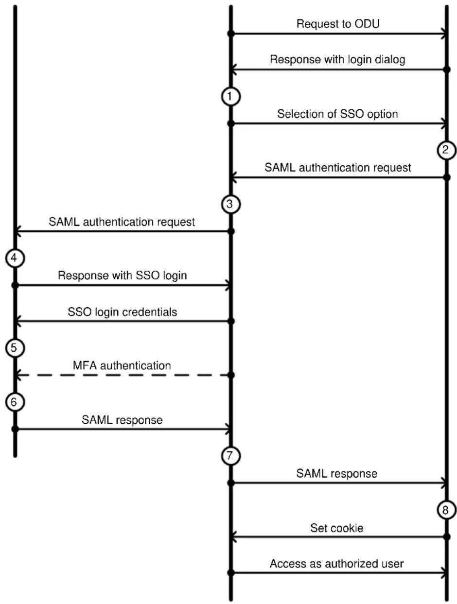
flowchart
graph TD
    A["Request to ODU"] --> B["Response with login dialog"]
    B --> C["Selection of SSO option"]
    C --> D["SAML authentication request"]
    D --> E["SAML authentication request"]
    E --> F["Response with SSO login"]
    F --> G["SSO login credentials"]
    G --> H["MFA authentication"]
    H --> I["SAML response"]
    I --> J["SAML response"]
    J --> K["Set cookie"]
    K --> L["Access as authorized user"]
SNMP control of passwords
PTP 700 allows the role-based and identity-based passwords for the web-based interface to be updated using the proprietary SNMP MIB. This capability is controlled by the SNMP Control of Passwords, and is disabled by default. SNMP Control of Passwords is automatically and permanently disabled in the FIPS 140-3 mode.
SNMP Control of Passwords can be used together with SNMPv3 to provide a secure means to update passwords from a central network manager. Password complexity rules configured in the web interface are applied to passwords updated using SNMP.
Further reading
| For information about... | Refer to... |
| How to plan the use of RADIUS | Planning for RADIUS operation on page 3-77 |
| How to plan the use of SSO | Error! Reference source not found. on page Error! Bookmark not defined. |
| How to configure RADIUS | RADIUS Configuration page on page 6-89 |
| How to configure SSO | SSO Configuration page on page 6-91 |
SNMP
The management agent supports configuration, fault and performance management by means of an SNMP interface. The management agent is compatible with SNMP v1, SNMP v2c, and SNMPv3.
Standard MIBs
PTP 700 supports the following Management Information Bases (MIBs):
• RFC-1493. BRIDGE-MIB. dot1dBase group.
• RFC-2233. IF-MIB. Interfaces group, and ifXTable table.
• RFC-3411. SNMP-FRAMEWORK-MIB. snmpEngine group.
• RFC-3412. SNMP-MPD-MIB. snmpMPDStats group.
- RFC-3413. SNMP-TARGET-MIB. snmpTargetObjects group and SNMP-NOTIFICATION-MIB snmpNotifyTable table.
- RFC-3414. SNMP-USER-BASED-SM-MIB. usmStats group and usmUser group.
• RFC-3415. SNMP-VIEW-BASED-ACM-MIB vacmMIBObjects group.
• RFC-3418. SNMPv2-MIB. System group, SNMP group, and set group.
• RFC-3826. SNMP-USM-AES-MIB. usmAesCfb128Protocol OID.
• RFC-4293 IP-MIB, ipForwarding, ipAdEntAddr, ipAdEntIfIndex, ipAdEntNetMask
Enterprise MIB
PTP 700 is managed using the following enterprise MIB:
- PTP 700 Series proprietary MIB.
SNMP Configuration Mode
PTP 700 supports configuration management via SNMP with a transactional model, and validation of the requested configuration equivalent to validation in the web-based management interface.
Configuration management using SNMP addresses approximately the same range of user-configurable attributes as the System Administrator role in the web-based interface.
Further reading
| For information about... | Refer to... |
| Planning for for SNMPv1/2c | Planning for SNMP operation on page 3-61 |
| Planning for SNMP Configuration Mode | SNMP Configuration Mode on page 3-62 |
| How to enable SNMP control of HTTP, Telnet and passwords | Web-Based Management page on page 6-83HTTP and Telnet options on page 6-132. |
| How to configure SNMPv1 or SNMPv2c | SNMP pages (for SNMPv1/2c) on page 6-115 |
| How to upgrade firmware remotely using Trivial FTP (TFTP) triggered by SNMP | Upgrading firmware using TFTP on page 6-155 |
Standalone management of TD-90
The TD-90 antenna positioner can be managed directly from a suitable Network Management System (NMS), using the TD-90 web-based management interface or using SNMP. Secure network management is provided using SNMPv3.
In this scenario, the TD-90 and PTP 700 are managed independently.

Note The TD-90 antenna positioner cannot be used at an HCMP Master ODU.
Integrated management of TD-90
PTP 700 provides optional integrated network management for the TD-90 antenna positioner. In this case, the TD-90 is managed by the NMS via the web-based management interface or SNMP interface of the PTP 700, with the PTP 700 acting as an SNMP Proxy.
The connection between the PTP 700 and the NMS may be secured using the standard PTP 700 HTTPS or SNMPv3 features.
The connection between the ODU and the TD-90 is on an isolated, directly-connected Ethernet link using SNMPv1 or SNMPv2c.
SNMP Proxy
In the integrated management scenario for TD-90, the PTP 700 ODU acts as an SNMP Proxy Forwarder.
The Proxy Forwarder consists of:
- The standard SNMP Agent function that receives GET and SET commands from the NMS in the Management Service. The Enterprise MIB for the PTP 700 includes objects that model all the managed functions of the TD-90, and is therefore a superset of the TD-90 MIB. The SNMP Agent supports SNMPv1, SNMPv2c and SNMPv3.
- Web pages in the PTP 700 web-based management interface that duplicate pages of the TD-90 web-based management. Controls in the PTP 700 web pages are linked to attributes in the PTP 700 data manager.
• Non-volatile storage in the PTP 700 data manager for attributes relating to TD-90 configuration
• Volatile storage in the PTP 700 data manager for attributes relating to TD-90 status - A translation function mapping attributes in the PTP 700 data manager to the SNMP objects in the TD-90 Enterprise MIB.
- An SNMP Manager that generates GET and SET commands sent to the attached TD-90, and processes GET RESPONSE and SET RESPONSE messages received from the TD-90. All communication between the PTP 700 and the TD-90 is in the isolated TD-90 Service. The SNMP Manager supports SNMPv1 and SNMPv3.
Offline configuration
The TD-90 can be configured in the PTP 700 when the TD-90 is offline. Stored configuration for the TD-90 is passed to the TD-90 when the connection is subsequently re-established, or when the TD-90 is reset.
SNMP Agent for antenna alignment
The PTP 700 provides a separate instance of the SNMP Agent attached to the TD-90 Service allowing the TD-90 to obtain signal strength and link status information from the PTP 700 to support the alignment and tracking function.
IP interface
PTP 700 provides a dedicated IPv4 interface for connection to the TD-90 in the TD-90 Service. This interface is configured automatically. The IP address is set to one of two values depending on the Master/Slave status of the ODU.
Discovery
The TD-90 antenna positioner uses a discovery method to detect the IP interface in the PTP 700 TD-90 Service at the Master or Slave ODU. The discovery method is armed by resetting the TD-90 to factory defaults. The TD-90 selects its own IP address automatically following discovery of an attached PTP 700.

Note The TD-90 antenna positioner cannot be used at an HCMP Master ODU.
Further reading
| For information about... | Refer to... |
| TD-90 Operation and Maintenance | Cambium TD-90 User Guide |
| Ethernet bridging in the TD-90 Service | TD-90 Service on page 1-52 |
| Ethernet port allocation for TD-90 | Ethernet port allocation on page 3-48 |
System Clock
The System Clock supplies accurate date and time information to the system. It can be set manually, configured to synchronize at regular intervals to a network time server using SNTP, or configured to synchronize at registration with a connected cnMaestro server.
The System Clock is configured to display local time by setting the time zone and daylight saving in the Time Configuration web page.
PTP 700 can be configured to authenticate received NTP messages using an MD5 or SHA-1 signature.
Further reading
| For information about... | Refer to... |
| How to plan for SNTP operation | Planning for SNTP operation on page 3-69 |
| How to configure SNTP | Time Configuration page on page 6-99 |
SNMPv3 security
SNMP Engine ID
PTP 700 supports four different formats for SNMP Engine ID:
- MAC address
- IPv4 address
- Configurable text string
- IPv6 address
SNMPv3 security configuration is re-initialized when the SNMP Engine ID is changed.
User-based security model
PTP 700 supports the SNMPv3 user-based security model (USM) for up to 10 users, with MD5, SHA-1, DES and (subject to the license key) AES protocols in the following combinations:
- MD5, no privacy,
- SHA-1, no privacy,
- MD5, DES,
- SHA-1, DES,
- MD5, AES,
- SHA-1, AES.
- No authentication, no privacy,
Use of AES privacy requires the PTP 700 AES upgrade described in AES license on page 1-76.
View-based access control model
PTP 700 supports the SNMPv3 view-based access control model (VACM) with a single context. The context name is the empty string. The context table is read-only, and cannot be modified by users.
Access to sensitive security parameters
The SNMPv3 management interface does not provide access to sensitive security parameters (SSPs) of PTP 700 except for the security configuration of the SNMPv3 interface itself.
MIB-based management of SNMPv3 security
PTP 700 supports a standards-based approach to configuring SNMPv3 users and views through the SNMP MIB. This approach provides maximum flexibility in terms of defining views and security levels appropriate for different types of user.
PTP 700 provides a default SNMPv3 configuration. This initial configuration is not secure, but it provides the means by which a secure configuration can be created using SNMPv3.
The secure configuration should be configured in a controlled environment to prevent disclosure of the initial security keys necessarily sent as plaintext, or sent as encrypted data using a predictable key. The initial security information should not be configured over an insecure network.
The default configuration is restored when any of the following occurs:
- All ODU configuration data is erased.
- All SNMP users are deleted using the SNMP management interface.
- The SNMP Engine ID Format has been changed.
• The SNMP Engine ID Format is Internet Address AND the Internet Address has been changed. - The SNMP Engine ID Format is Text String AND the text string has been changed.
- The SNMP Engine ID Format is MAC Address AND configuration has been restored using a file saved from a different unit.
- SNMPv3 Security Management is changed from web-based to MIB-based.
The default user configuration is specified in SNMPv3 default configuration (MIB-based) on page 3-75.
PTP 700 creates the initial user and template users with localized authentication and privacy keys derived from the passphrase string 123456789. Authentication keys for the templates users are fixed and cannot be changed. Any or all of the template users can be deleted.
The default user initial is created with a view of the entire MIB, requiring authentication for SET operations. There is no access for template users.

Note VACM grants access for requests sent with more than the configured security level.
The default user initial will have read/write access to the whole of the MIB. This is described in further detail in View-based access control model on page 1-73. The template users have no access to the MIB in the default configuration. User initial will normally be used to create one or more additional users with secret authentication and privacy keys, and with appropriate access to the whole of the MIB or to particular views of the MIB according to the operator's security policy. New users must be created by cloning template users. The user initial may then be deleted to prevent access using the well-known user name and keys. Alternatively, the keys associated with initial may be set to some new secret value.
Web-based management of SNMPv3 security
PTP 700 supports an alternative, web-based approach for configuring SNMPv3 security. In this case, the web-based interface allows users to specify SNMPv3 users, security levels, privacy and authentication protocols, and passphrases. Web-based management will be effective for many network applications, but the capabilities supported are somewhat less flexible than those supported using the MIB-based security management.
Selection of web-based management for SNMPv3 security disables the MIB-based security management.
Web-based management of SNMPv3 security allows for two security roles:
- Read Only
• System Administrator
Read Only and System Administrator users are associated with fixed views allowing access to the whole of the MIB, excluding the objects associated with SNMPv3 security. System Administrators have read/write access as defined in the standard and proprietary MIBs.
Web-based management of SNMPv3 security allows an operator to define the security levels and protocols for each of the security roles; all users with the same role share a common selection of security level and protocols.
Web-based security configuration is re-initialized when any of the following occurs:
- All ODU configuration data is erased.
- The SNMP Engine ID Format has been changed.
• The SNMP Engine ID Format is Internet Address and the Internet Address has been changed.
• The SNMP Engine ID Format is Text String and the text string has been changed. - The SNMP Engine ID Format is MAC Address and configuration has been restored using a file saved from a different unit.
- SNMPv3 Security Management is changed from MIB-based to web-based.
Additionally, all SNMP user accounts are disabled when the authentication protocol, the privacy protocol, or the security level is changed.
Downgrade of the license key
A possible lockout condition exists if a user downgrades the PTP 700 license key so as to disable the AES capability when SNMPv3 users are configured with AES privacy and VACM is configured to require privacy. In this case, recovery is by either (a) restoring the correct license key, or (b) using recovery mode to reset all configuration and entering new configuration.
Option (b) will cause default users and access configuration to be re-created.
Further reading
| For information about... | Refer to... |
| How to plan for SNMPv3 operation | Planning for SNMPv3 operation on page 3-73 |
| How to configure SNMPv3 | SNMP pages (for SNMPv3) on page 6-106 |
System logging (syslog)
PTP 700 supports the standard syslog protocol to log important configuration changes, status changes and events. The protocol complies with RFC 3164.
PTP 700 creates syslog messages for configuration changes to any attribute that is accessible via the web-based interface, or via the enterprise MIB at the SNMP interface.
PTP 700 additionally creates syslog messages for changes in any status variable displayed in the web-based interface.
PTP 700 creates syslog messages on a number of events (for example successful and unsuccessful attempts to log in to the web-based interface).
PTP 700 can be configured to send syslog messages to one or two standard syslog servers.
Additionally, PTP 700 logs event notification messages locally. Locally-stored event messages survive reboot of the unit, and are overwritten only when the storage capacity is exhausted (approximately 2000 messages). The locally stored events can be reviewed using the web-based user interface.
Only users with Security Officer role are permitted to configure the syslog client. Users with Security Officer, System Administrator or Read Only roles are permitted to review the locally logged event messages.
Further reading
| For information about... | Refer to... |
| Configuring system logging | Syslog Configuration page on page 6-104 |
| Syslog alarms | Alarms on page 7-24 |
| How to view the local log of event messages | Syslog page on page 7-28 |
| How to interpret syslog messages | Format of syslog server messages on page 7-29 |
Domain Name Service (DNS)
The PTP 700 Management Agent supports use of an external DNS server to resolve the Domain Name configured for network management servers to IPv4 or IPv6 addresses. PTP 700 allows the configuration of a primary DNS server and optionally a second DNS server.
When DNS is enabled and configured, the following server addresses can be configured as a Fully Qualified Domain Name (FQDN):
- cnMaestro Server
- RADIUS Server
- SMTP Server
- SNMP Trap
- SNTP Server
- Syslog Server
- TFTP Server
The FQDN must comply with the following:
• Not longer than 63 characters
- Must contain some structure (at least one “.”)
- Must consist of only the characters "0".."9", "a".."z", "A".."Z", "\$", hyphen, underscore, dot/stop, plus, exclamation, star, single quote, left parenthesis, right parenthesis
Instant messaging
PTP 700 provides a simple text-based messaging service between the ODUs in a link. The Instant Messaging interface can be used to send messages to a technician or operator at the remote end of the link. The messaging service does not depend on external servers and can be used as soon as basic connectivity is achieved.
The maximum message size is 180 characters.
Unread messages are indicated by an alert in the Status Bar of the web-based interface.
AES license
PTP 700 provides optional encryption using the Advanced Encryption Standard (AES). Encryption is not available in the standard PTP 700 system.
AES upgrades are purchased from your Cambium Point-to-Point distributor or solutions provider. The upgrade authorizes AES operation for one ODU. Two upgrades are needed to operate AES on a link.
AES encryption may be used in the following ways:
- At the wireless port to encrypt data transmitted over the wireless link.
- At the SNMP management interface in the SNMPv3 mode.
- At the HTTPS/TLS management interface.
Two levels of encryption are available to purchase:
- 128-bit: This allows an operator to encrypt all traffic sent over the wireless link using 128-bit encryption.
• 256-bit: This allows an operator to encrypt traffic using either 128-bit or 256-bit encryption.
Wireless encryption can be configured for TLS RSA, TLS PSK 128-bit, or TLS PSK 256-bit algorithms. TLS RSA uses factory installed or user-supplied RSA device certificates to authorize remote units. TLS RSA automatically uses the largest key size mutually supported by licensing at the two ends of the link. TLS PSK algorithms using a 128-bit or 256-bit pre-shared key are available only if the associated key size is supported by licensing at both ends of the link.
AES encryption for SNMPv3 is always based on a 128-bit key, regardless of level enabled in the PTP 700 license key.

Note that the connection between the PTP 700 and the cnMaestro server is always encrypted using TLS 1.3 with AES. The optional AES license is not required for secure operation with cnMaestro.
Further reading
| For information about... | Refer to... |
| General description of wireless encryption in PTP 700 | Wireless encryption on page 1-39 |
| Capability upgrades for AES | Capability upgrades on page 1-78 |
| AES and HTTPS/TLS operation | Planning for HTTPS/TLS operation on page 3-72 |
| AES and SNMPv3 operation | Planning for SNMPv3 operation on page 3-73 |
| How to generate an AES license key | Generating license keys on page 6-2 |
| How to enable AES capability | Software License Key page on page 6-16 |
| How to configure AES encryption | System Configuration page on page 6-56 |
| How to configure security with AES | Security menu on page 6-122 |
Firmware upgrade
The management agent supports application firmware upgrade using either the web-based interface or the SNMP interface.
PTP 700 firmware images are digitally signed, and the ODU will accept only images that contain a valid Cambium Networks digital signature. The ODU always requires a reboot to complete a firmware upgrade.

Note Obtain the application firmware and this user guide from the support website.

Attention ODU firmware version must be the same at both ends of the link. Limited operation may sometimes be possible with dissimilar firmware versions, but such operation is not supported by Cambium Networks.

Attention Take care when upgrading ODU firmware using the wireless link to a remote ODU. Upgrade the remote unit first, reboot the remote ODU, and then upgrade the local unit to the same firmware version.
Transition of digital signature algorithms
Application firmware from System Release 700-04-10 onwards accepts only replacement firmware signed using the Edwards Curve Digital Signature Algorithm (EdDSA). Firmware with a EdDSA signature is indicated by a file extension of DLD3.
Application firmware from releases earlier than 700-04-10 accepts only replacement firmware signed using the Digital Signature Algorithm (DSA), indicated by a file extension of DLD2.
Firmware for System Release 700-04-10 is available for download from the support website and includes separate firmware images with EdDSA signature (DLD3) and DSA signature (DLD2).
Recovery firmware from RECOVERY-02-00 onwards accepts only DLD3. Earlier versions of Recovery accept only DLD2.


Note Install firmware PTP45700-04-10.DLD2 or PTP78700-04-10.DLD2 to upgrade from an earlier release to 700-04-10.
Attention EdDSA provides enhanced security. DSA is deprecated for security-critical applications. A PTP 700 ODU with Application firmware 700-04-10 or later, and Recovery firmware RECOVERY-02-00 or later, cannot be downgraded to a release earlier than 700-04-10 by any means.
Further reading
| For information about... | Refer to... |
| How to upgrade the firmware using the web interface | Software Upgrade page on page 6-80 |
| How to upgrade firmware remotely using Trivial FTP (TFTP) triggered by SNMP | Upgrading firmware using TFTP on page 6-155 |
Capability upgrades
ODUs are shipped with a default License Key factory-installed. The default license key enables a limited set of capabilities which depend upon the ODU variant.
Capability upgrades are purchased from Cambium and supplied as an Entitlement Certificate, delivered by email. One Entitlement Certificate can deliver multiple upgrades. Follow the instructions in the certificate to redeem the purchased upgrade products at the Cambium Support Center.
Individual upgrades can then be activated by specifying the MAC address of a PTP 700 ODU. For each upgrade activated, the Support Center creates a new license key and delivers it by email. Install the license key using the ODU web interface to enable the purchased capability in the ODU.

Note License keys are bound to a single ODU and are not transferrable.
Further reading
| For information about... | Refer to... |
| Capabilities of the PTP 45700 Connectorized+Integrated ODU | PTP 45700 Connectorized+Integrated ODU on page 2-3 |
| Capabilities of the PTP 45700 Connectorized ODU | PTP 45700 Connectorized ODU on page 2-6 |
| Capabilities of the PTP 45700 Beam Steering ODU | PTP 45700 Beam Steering ODU on page 2-8 |
| Capabilities of the PTP 78700 Integrated ODU | PTP 78700 Integrated ODU on page 2-9 |
| Capabilities of the PTP 78700 Connectorized ODU | PTP 78700 Connectorized ODU on page 2-10 |
| Ordering capability upgrades | ODU capability upgrades on page 2-12 |
| How to obtain License Keys | Generating license keys on page 6-2 |
| How to install capability upgrades | Software License Key page on page 6-16 |
Full capability trial period
A full capability trial period is available for PTP 45700 units that are licensed for "Lite" (up to 225 Mbps) data throughput capability. This trial allows the ODU to operate with "Full" capability (up to 450 Mbps) during a 60 day period, reverting to the Lite capability afterwards. The trial period can be started, paused and resumed from the web interface.

Note PTP 45700 does not support HCMP topology in units with the Lite capacity variant, and the trial period is therefore not applicable to HCMP operation.
Further reading
| For information about... | Refer to... |
| How to control the trial period | Software License Key page on page 6-16 |
Recovery mode
The PTP 700 recovery mode provides a means to recover from serious configuration errors including lost or forgotten passwords and unknown IP addresses.
Recovery mode also allows new main application firmware to be loaded even when the integrity of the existing main application firmware image has been compromised. The most likely cause of an integrity problem with the installed main application firmware is where the power supply has been interrupted during an earlier firmware upgrade.
The ODU operates in recovery mode in the following circumstances:
- When a checksum error occurs for the main application firmware image.
- When a power on, power off, power on cycle is applied to the ODU with the power off period being around 5sec.
Recovery mode supports a single IPv4 interface, with IP address 169.254.1.1, and with default link settings. Recovery mode does not support IPv6.

Note When Recovery has been entered through a power on/off/on cycle, the ODU will revert to normal operation if no web access has been made to the unit within 30 seconds. This prevents the unit remaining inadvertently in recovery following a power outage.
Recovery mode options
Options in recovery mode (IPv4 only) are as follows:
- Load new main application firmware.
- Reset all configuration data. This option resets IP, Ethernet and security configuration
- Reset IP and Ethernet configuration.
- Reset (zeroize) sensitive security parameters.
- Reboot with existing firmware and configuration.
If recovery mode has been entered because of a checksum error, after a 30 second wait the ODU will attempt to reboot with existing firmware and configuration.
The recovery firmware image is installed during manufacture of the ODU and cannot be upgraded by operators.
Further reading
| For information about... | Refer to... |
| How to recover from configuration errors or firmware image corruption | Recovery mode on page 7-80 |
Upgrade from earlier releases
PTP topology
To upgrade a PTP link to 700-04-10, upload the new firmware to the ODUs at the two ends of the link, program the firmware image into non-volatile memory in the two ODUs, and then reboot both ODUs together.
HCMP topology
To upgrade an HCMP sector to 700-04-10, upload the new firmware to all of the ODUs, program the firmware image into non-volatile memory in the ODUs, and then reboot all ODUs together.

Note Upgrade new Slave ODUs with earlier firmware to 700-04-10 before installing on the upgraded Master ODU.

Note See Transition of digital signature algorithms on page 1-78 for details of a transition in digital signatures of replacement firmware.
FIPS 140-3 mode
This section describes the (optional) FIPS 140-3 cryptographic mode of operation.
PTP 700 provides an optional secure cryptographic mode of operation that complies with the requirements for Level 2 of Federal Information Processing Standards (FIPS) Publication 140-3.
FIPS 140-3 approved mode
PTP 700 operates in the FIPS 140-3 approved mode whenever the special FIPS firmware is installed in the PTP 700 ODU.

Attention Use the following NIST web site to confirm that the FIPS firmware has been validated: https://csrc.nist.gov/Projects/cryptographic-module-validation-program/validated-modules/search
The special FIPS firmware image can be identified by a FIPS- prefix to the filename, for example: FIPS-PTP700-04-10.DLD3.

Note PTP 700 will not upload the FIPS firmware unless the unit is licensed for 128-bit or 256-bit AES encryption and for FIPS operation.
Indication of FIPS 140-3 approved mode
The FIPS 140-3 approved mode is indicated by the "FIPS 140-3" text displayed at the top of the navigation bar in the web-based interface, as shown in Figure 7.
Figure 7 Indication of FIPS 140-3 capability

Enforced configuration in FIPS approved mode
When the PTP 700 ODU operates in the FIPS approved mode, the following configuration settings are automatically enforced:
- Identity-based user accounts is Enabled.
- Telnet management interface is Disabled.
• SNMP control of HTTP and Telnet is Disabled.
• SNMP control of passwords is Disabled.
• TFTP client is Disabled.
• RADIUS client is Disabled.
• Device Certificate is User.
In addition, the License Key must have a valid EdDSA signature.
Secure mode alarm
The Secure mode alarm indicates that the unit is operating in the FIPS approved mode, but that it has not been configured correctly for FIPS 140-3 operation. The secure mode alarm appears in the System Summary page as shown in Figure 8.
Figure 8 Secure mode alarm in the System Summary page
| System Summary | ||
| Attributes | Value | Units |
| Wireless Link Status | Searching | |
| Link Name | Pikes Peak to Cripple Creek | |
| Elapsed Time Indicator | 00:01:01 | |
| Secure Mode Alarm | Secure Mode Is Not Configured | |
The Secure mode alarm is also displayed in the first page of the Security Wizard as shown in Figure 9.
Figure 9 Secure mode alarm in the Security Wizard

Security configuration for FIPS approved mode
The security configuration for the FIPS approved mode consists of the following:
• Key of keys (128-bit or 256-bit to match the AES license)
- Entropy (512-bit)
- The HTTPS/TLS management interface must be correctly configured, including:
- Private key (2048-bit RSA key size)
- Public key certificate (2048-bit RSA key size, signed using SHA2-256 Secure Hash Algorithm)
- The HTTP management interface must be Disabled
• AES encryption must be configured and enabled at the wireless interface.
- Passwords must be configured (with minimum length 15 characters) for enabled accounts in the web-based interface.
When the security configuration is completed correctly, the Secure mode alarm is cleared from the System Summary page and the Security Wizard displays the Active state as shown in Figure 10.
Figure 10 Secure mode active
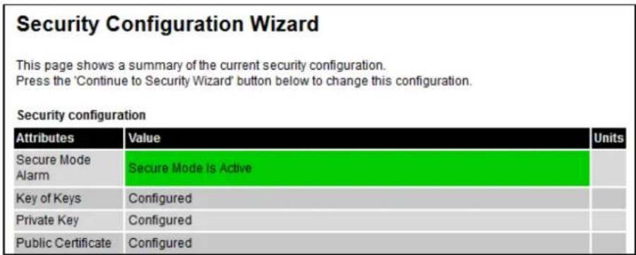
Further reading
| For information about... | Refer to... |
| Cryptographic material needed for FIPS operation | Planning for FIPS 140-3 operation on page 3-80 |
| Installing license keys | Software License Key page on page 6-16 |
| Loading firmware images | Software Upgrade page on page 6-80 |
| Configuring the ODU for FIPS operation | Configuring security for FIPS 140-3 applications on page 6-137 |
Exiting from the FIPS operational state
A PTP 700 ODU in the FIPS operation state can be prepared to accept new security configuration by zeroizing sensitive security parameters (SSPs). The unit remains in the FIPS approved mode.
Further reading
| For information about... | Refer to... |
| Zeroizing the SSPs | Zeroize SSPs page on page 6-136 |
Reverting to the standard (non-FIPS) mode
A FIPS 140-3 capable ODU can be used in standard (non-FIPS) mode by loading a standard (non-FIPS) firmware image and rebooting.
The sensitive security parameters (SSPs) are zeroized when the unit is no longer FIPS 140-3 capable.
Further reading
| For information about... | Refer to... |
| Exiting the FIPS approved mode | Managing security on page 7-57 |
This chapter describes the hardware components of a PTP 700 link.
The following topics are described in this chapter:
- Outdoor unit (ODU) on page 2-2 describes ODU hardware variants, upgrades, accessories, cables, and brackets.
• Power supply units (PSU) on page 2-20 contains details of the AC+DC Enhance Power Injector. - Antennas and antenna cabling on page 2-24 lists cable and connector types for antenna connections, together with the RF Combiner Kit used in some protected links.
- Ethernet cabling on page 2-27 lists ready made data cables for PTP 78700 and specifies approved Ethernet cable and connectors for permanent or infrastructure deployments. This section also deals with Lightning Protection Units (LPUs) and SFP modules.
- PTP-SYNC unit on page 2-37 provides information about the optional PTP-SYNC unit used for TDD Synchronization with PTP 45700.
• GPS receivers on page 2-43 describes the Trimble Acutime GPS receiver used with PTP-SYNC.
Outdoor unit (ODU)
ODU description
The ODU is a self-contained transceiver unit that houses both radio and networking electronics.
Two ODUs are required for a PTP link.
One ODU is required as a Master in an HCMP sector, with up to eight ODUs configured as Slaves.
Hardware platform variants
PTP 700 ODUs are available in five different hardware platform and frequency variants:
• PTP 45700 Connectorized+Integrated ODU (4400-5875 MHz)
• PTP 45700 Connectorized ODU (4400-5875 MHz)
- PTP 45700 Beam Steering ODU (4400-5875 MHz)
• PTP 78700 Integrated ODU (7125-8500 MHz)
• PTP 78700 Connectorized ODU (7125-8500 MHz)
PTP 700 ODUs are available in three color schemes:
- White
- Green
- Desert Tan
Regional variants
PTP 700 ODUs are available as a Global variant.
In PTP 45700 ODUs, the default License Key for country “Other” supports the following regulatory bands:
• 8 "5.4 GHz unrestricted"
• 35 "5.8 GHz unrestricted"
• 61 "4.9 GHz unrestricted"
• 62 "5.2 GHz unrestricted"
• 81 "4.7 GHz NATO Band IV"
ODUs may be configured for individual country licenses. Refer to Generating license keys on page 6-2 and Software License Key page on page 6-16. The list of available regulatory bands depends on the country.
PTP 45700 ODU kits (see Table 7, Table 10) provide an option to order CE-marked ODUs. CE marking indicates that the upgraded ODU complies with all applicable EU regulations including EMC, safety, hazardous materials, and wireless. CE-marked ODUs can only be used with country-specific License Keys for countries that are EU members, EEA members, or Turkey. These licenses necessarily restrict the maximum power that can be transmitted in 5 GHz bands to comply with EU regulations. Operation in 4 GHz bands is not regulated by the EU and is unchanged from the Global variant.
PTP 45700 Beam Steering ODUs and PTP 78700 ODUs are supplied exclusively for use of governments and public safety and carry the CE marking without restriction on the wireless capabilities.
Capacity variants
Some of the PTP 45700 ODU models were previously available in a Lite capacity variant. The Lite capacity variant provides data transfer capped at half the capacity of the equivalent configuration in the Full capacity variant. The Lite capacity variant is no longer available from Cambium Networks. Existing ODUs licensed for Lite capacity can be operated at the reduced capacity, or can be licensed for the Full capacity by purchase of an upgrade (see ODU capability upgrades on page 2-12).
PTP 45700 Connectorized+Integrated ODU
The PTP 45700 Connectorized+Integrated ODU provides a choice between using external antennas, similar to the Connectorized ODU, or a 22 dBi integrated antenna (Figure 11 and Figure 12). The integrated antenna offers a convenient and easily-deployed solution where the additional gain of external antennas is not needed.
Figure 11 PTP 45700 Connectorized+Integrated ODU - White (front and rear views)

natural_image
White rectangular electronic device labeled 'Cymbium Networks' against a black background (no other text or symbols visible)
natural_image
Exterior view of a white industrial electrical enclosure mounted on a metal pipe, with no visible text or symbols.Figure 12 PTP 45700 Connectorized+Integrated ODU -Desert Tan (front and rear views)

natural_image
Two views of a yellow electronic device casing, one showing top and side views with black connectors (no visible text or symbols)Capacity and capability licensing
PTP 45700 ODUs support the following capacity and capability upgrades (see ODU capability upgrades on page 2-12):
- Lite to Full capacity upgrade
- SFP port operation
- AES encryption
• Synchronous Ethernet and 1588 Transparent Clock
• High-Capacity Multipoint (HCMP)
• Over-the air rekeying

Note The HCMP upgrade can only be applied to ODUs that have the Full capacity license.
Full capability trial period
A full capability trial period is available for PTP 45700 ODUs of the Lite capacity variant. This trial allows the ODU to operate with Full capacity during a 60 day period, reverting to Lite capability afterwards. The trial period can be started, paused and resumed from the web interface (Software License Key page on page 6-16).

Note The HCMP upgrade can only be applied to ODUs that already have the Full capacity license, and so the Full capability trial does not apply to ODUs operating in the HCMP topology.
Individual ODU part numbers
Order PTP 45700 Connectorized+Integrated ODUs from Cambium Networks (Table 5). ODUs are supplied without mounting brackets.
Table 5 PTP 45700 Connectorized+Integrated ODU individual part numbers
| Cambium description | Capacity variant | Cambium part number |
| PTP 700 Connectorized+Integrated ODU (Global), White, 4400-5875 MHz | Full | C045070B004A |
| PTP 700 Connectorized+Integrated ODU (Global), Green, 4400-5875 MHz | Full | C045070B038A |
| PTP 700 Connectorized+Integrated ODU (Global), Desert Tan, 4400-5875 MHz | Full | C045070B040A |
PTP 700 Lite
The Lite capacity PTP 45700 ODU (Table 6) is no longer available from Cambium Networks. Existing Lite capacity ODUs are supported in the PTP 700 firmware and can be upgraded to the Full capacity license (see ODU capability upgrades on page 2-12).
Table 6 PTP 700 Lite Connectorized+Integrated individual ODU part numbers
| Cambium description | Capacity variant | Cambium part number |
| PTP 700 Lite Connectorized+Integrated ODU (Global), White, 4400-5875 MHz | Lite | C045070B010A |
ODU kit part numbers
Order PTP 45700 Connectorized+Integrated ODU kits from Cambium Networks (Table 7).
Each of the parts listed in Table 7 includes the following items:
• One Connectorized+Integrated ODU (Global).
- Upgrade to apply CE marking to the ODU.
Table 7 PTP 45700 ODU kit part numbers for Connectorized+Integrated ODUs
| Cambium description | Capacity variant | Cambium part number |
| PTP 700 Connectorized+Integrated ODU with CE mark, White, 4400-5875 MHz | Full | C045070H032A |
| PTP 700 Connectorized+Integrated ODU with CE mark, Green, 4400-5875 MHz | Full | C045070H034A |
| PTP 700 Connectorized+Integrated ODU with CE mark, Desert Tan, 4400-5875 MHz | Full | C045070H036A |
PTP 45700 Connectorized ODU
The PTP 45700 Connectorized ODU is intended to work with separately mounted external antennas (Figure 13). External antennas generally have higher gains than the integrated antennas, allowing the PTP 700 to cope with more difficult radio conditions.
Figure 13 PTP 45700 Connectorized ODU - White (front and rear views)

natural_image
Two views of a metallic industrial component with internal features and mounting brackets, shown against black background (no text or symbols)Figure 14 PTP 45700 Connectorized ODU - Green (front and rear views)

natural_image
Two green industrial electronic devices with heat sinks and connectors, shown from front and side views (no visible text or symbols)
Note To determine when to install external antennas and to calculate their impact on link performance and regulatory limits, see Planning for connectorized units on page 3-30.
To select antennas, RF cables and connectors for connectorized units, see Antennas and antenna cabling on page 2-24.
Capacity and capability licensing
PTP 45700 ODUs support the following capacity and capability upgrades (see ODU capability upgrades on page 2-12):
- Lite to Full capacity upgrade
- SFP port operation
- AES encryption
• Synchronous Ethernet and 1588 Transparent Clock
• High-Capacity Multipoint (HCMP)
• Over-the air rekeying
Full capability trial period
A full capability trial period is available for PTP 45700 ODUs of the Lite capacity variant. This trial allows the ODU to operate with Full capacity during a 60 day period, reverting to Lite capability afterwards. The trial period can be started, paused and resumed from the web interface (Software License Key page on page 6-16).

Note The HCMP upgrade can only be applied to ODUs that already have the Full capacity license, and so the Full capability trial does not apply to ODUs operating in the HCMP topology.
Individual ODU part numbers
Order PTP 45700 Connectorized ODUs from Cambium Networks (Table 8). ODUs are supplied without mounting brackets.
Table 8 PTP 45700 Connectorized individual ODU part numbers
| Cambium description | Capacity variant | Cambium part number |
| PTP 700 Connectorized ODU (Global), White, 4400-5875 MHz | Full | C045070B003B |
| PTP 700 Connectorized ODU (Global), Green, 4400-5875 MHz | Full | C045070B034A |
| PTP 700 Connectorized ODU (Global), Desert Tan, 4400-5875 MHz | Full | C045070B039A |
PTP 700 Lite
The Lite capacity ODU (Table 9) is no longer available from Cambium Networks. Existing Lite capacity ODUs are supported in the PTP 700 firmware and can be upgraded to the Full capacity license (see ODU capability upgrades on page 2-12).
Table 9 PTP 45700 Lite Connectorized individual ODU part numbers
| Cambium description | Capacity variant | Cambium part number |
| PTP 700 Lite Connectorized ODU (Global), White, 4400-5875 MHz | Lite | C045070B009B |
ODU kit part numbers
Order PTP 45700 Connectorized ODU kits from Cambium Networks (Table 10).
The part listed in Table 10 includes the following items:
• One Connectorized ODU (Global).
- Upgrade to apply CE marking to the ODU.
Table 10 PTP 45700 ODU kit part numbers for Connectorized ODUs
| Cambium description | Capacity variant | Cambium part number |
| PTP 700 Connectorized ODU with CE mark, White, 4400-5875 MHz | Full | C045070H031A |
| PTP 700 Connectorized ODU with CE mark, Green, 4400-5875 MHz | Full | C045070H033A |
| PTP 700 Connectorized ODU with CE mark, Desert Tan, 4400-5875 MHz | Full | C045070H035A |
PTP 45700 Beam Steering ODU
The PTP 45700 Beam Steering ODU (Figure 15) provides an integrated, electronically steerable 21 dBi antenna, supporting automatic alignment. The Beam Steering ODU eliminates the need for manual alignment, leading to reduced effort for installers in tactical deployments, and minimizing exposure for installers in hazardous environments.
Figure 15 PTP 45700 Beam Steering ODU - White (front and rear views)

natural_image
White rectangular electronic device mounted on a pole against a dark background (no text or symbols visible)
natural_image
Exterior view of a white rectangular electronic device mounted on a vertical metal frame with mounting bolts (no visible text or symbols)Capability licensing
PTP 45700 Beam Steering ODUs support the following capability upgrades (see ODU capability upgrades on page 2-12):
- SFP port operation
- AES encryption
• Synchronous Ethernet and 1588 Transparent Clock
• High-Capacity Multipoint (HCMP)
• Over-the air rekeying
Individual ODU part numbers
Order PTP 45700 Beam Steering ODUs from Cambium Networks (Table 11).
Table 11 PTP 45700 Beam Steering ODU individual part numbers
| Cambium description | Cambium part number |
| PTP 700 Beam Steering ODU (Global), White, 4400-5875 MHz | C045070B041A |
| PTP 700 Beam Steering ODU (Global), Green, 4400-5875 MHz | C045070B042A |
| PTP 700 Beam Steering ODU (Global), Desert Tan, 4400-5875 MHz | C045070B043A |
PTP 78700 Integrated ODU
The PTP 78700 Integrated ODU incorporates a 26 dBi integrated antenna (Figure 16). The integrated antenna offers a convenient and easily deployed solution where the additional gain of external antennas is not needed.
Figure 16 PTP 78700 Integrated ODU - White (front and rear views)

natural_image
Two views of a white rectangular electronic device mounted on a pole, showing its exterior and internal structure (no text or symbols visible)Capability licensing
PTP 78700 ODUs support the following capability upgrades (see ODU capability upgrades on page 2-12):
- SFP port operation
- AES encryption
• Synchronous Ethernet and 1588 Transparent Clock
• High-Capacity Multipoint (HCMP)
• Over-the air rekeying
Individual ODU part numbers
Order PTP 78700 Integrated ODUs from Cambium Networks (Table 12). ODUs are supplied without mounting brackets.
Table 12 PTP 78700 Integrated ODU part numbers
| Cambium description | Capacity variant | Cambium part number |
| PTP 700 Integrated ODU (Global), White, 7125-8500 MHz | Full | C070070B002A |
| PTP 700 Integrated ODU (Global), Green, 7125-8500 MHz | Full | C070070B004A |
| PTP 700 Integrated ODU (Global), Desert Tan, 7125-8500 MHz | Full | C070070B006A |
PTP 78700 Connectorized ODU
The PTP 78700 Connectorized ODU is intended to work with separately mounted external antennas (Figure 17 and Figure 18). External antennas generally have higher gains than the integrated antennas, allowing the PTP 700 to cope with more difficult radio conditions.
Figure 17 PTP 78700 Connectorized ODU - Green (front and rear views)
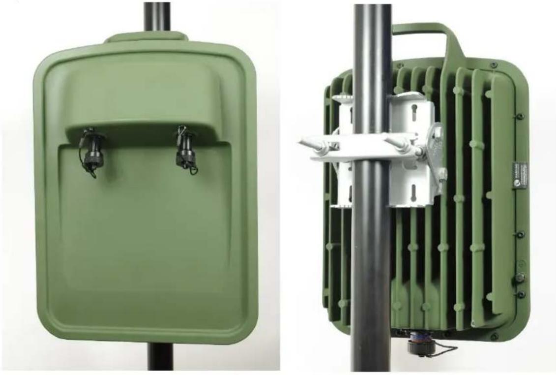
natural_image
Two green industrial equipment enclosures with metal clamps and connectors, mounted on a pole (no visible text or symbols)Figure 18 PTP 78700 Connectorized ODU - Desert Tan (front and rear views)

natural_image
Two beige electronic device modules with black connectors and mounting holes, shown from different angles (no text or symbols visible)
Note To determine when to install external antennas and to calculate their impact on link performance and regulatory limits, see Planning for connectorized units on page 3-30.
To select antennas, RF cables and connectors for connectorized units, see Antennas and antenna cabling on page 2-24.
Capability licensing
PTP 78700 ODUs support the following capability upgrades (see ODU capability upgrades on page 2-12):
- SFP port operation
- AES encryption
• Synchronous Ethernet and 1588 Transparent Clock
• High-Capacity Multipoint (HCMP)
• Over-the air rekeying
Individual ODU part numbers
Order PTP 78700 Connectorized ODUs from Cambium Networks (Table 13). ODUs are supplied without mounting brackets.
Table 13 PTP 78700 Connectorized ODU part numbers
| Cambium description | Capacity variant | Cambium part number |
| PTP 700 Connectorized ODU (Global), White, 7125-8500 MHz | Full | C070070B001A |
| PTP 700 Connectorized ODU (Global), Green, 7125-8500 MHz | Full | C070070B003A |
| PTP 700 Connectorized ODU (Global), Desert Tan, 7125-8500 MHz | Full | C070070B005A |
ODU capability upgrades
To upgrade a PTP 700 ODU to one or more new capabilities, order the necessary upgrades from Cambium Networks (Table 14). For details of how to install the capability upgrades, refer to Generating license keys on page 6-2 and Software License Key page on page 6-16.
Table 14 Capacity and capability upgrades available for PTP 700 Series ODUs
| Cambium description | Part number |
| PTP 700 128-bit AES Encryption - per END (*1) | C000070K001A |
| PTP 700 256-bit AES Encryption - per END (*1) | C000070K002A |
| PTP 700 Precise Network Timing Software License - per END | C000070K003A |
| PTP 700 FIPS 140 Upgrade including 128-bit AES - per END | C000070K005A |
| PTP 700 FIPS 140 Upgrade including 256-bit AES - per END | C000070K006A |
| PTP 700 Lite to Full Upgrade - per END (*2) | C000070K008A |
| PTP 700 High Capacity Multipoint Upgrade - per END (*3) | C000070K009A |
| PTP 700 Over-the-Air Rekey License (*4) | C000070K013A |
| Global to CE Conversion Kit (*5) | C045070K001A |
(*1) Cambium Networks will supply AES upgrades only if there is official permission to export AES encryption to the country of operation.
(*2) The Lite to Full upgrade can be applied to PTP 45700 Lite ODUs.
(*3) Order one upgrade for every ODU that will be used as a TDD Master or TDD Slave in an HCMP sector. The HCMP upgrade can only be applied to ODUs that already have the Full capacity license.
(*4) Order one upgrade for every ODU that will be used as a TDD Master in an HCMP sector or PTP link.
(*5) The upgrade to apply CE marking is applied in the Distribution Centre when the ODU is ordered as part of an ODU Kit (C045070H031A, C045070H032A, C045070H033A, C045070H034A, C045070H035A, C045070H036A). The conversion kit (C045070K001A) cannot be ordered separately.
ODU accessories
ODU accessories available from Cambium Networks are listed in Table 15.
Table 15 ODU accessory part numbers
| Cambium description | Cambium part number |
| Blanking Plug Pack (Qty 10) | N000065L036A |
ODU cables
Use the following cables to connect the PTP 78700 ODU to the top LPU:
Table 16 ODU cables for PTP 78700 ODUs
| Cambium description | Cambium part number |
| PTP 700 Drop Cable 38999 to 1 x RJ45 male extension Cable 2' | N000070L018A |
| PTP 700 Drop Cable 38999 to 2 x RJ45 male extension Cable 2' | N000070L019A |
ODU mounting brackets
The Tilt Bracket Assembly (Figure 19) and Heavy Duty Mounting Bracket (Integrated) bracket (Figure 20) are used to mount a PTP 700 ODU on a pole with diameter in the range 40 mm to 80 mm (1.6 inches to 3.1 inches). The Tilt Bracket Assembly may be used with third-party band clamps to mount an ODU on pole with diameter in the range 90 mm to 230 mm (3.6 inches to 9.0 inches).
The Smart Antenna Clamp Set (Figure 21) is used to mount a PTP 45700 Beam Steering ODU on a pole with diameter in the range 40 mm to 100 mm (1.6 inches to 3.9 inches)
Order ODU mounting brackets from Cambium Networks (Table 17).
Figure 19 ODU Tilt Bracket Assembly

natural_image
Two views of a metal automotive bracket assembly: one showing a frame with bolts and joints, the other showing disassembled parts including bolts, screws, and bolts (no text or symbols visible)Figure 20 ODU Heavy Duty Mounting Bracket (Integrated)

natural_image
Two metallic automotive components with bolts and fasteners, shown from different angles (no text or symbols visible)Figure 21 Smart Antenna Clamp Set

natural_image
Collection of metal mechanical components including clips, bolts, and screws arranged on a plain surface (no text or symbols visible)Table 17 ODU mounting bracket part numbers
| Bracket | ODU variants | Bracket part number |
| Tilt Bracket Assembly | PTP 700 IntegratedPTP 700 Connectorized+IntegratedPTP 700 Connectorized | N000045L002A |
| Heavy Mounting Bracket (Integrated) | PTP 700 IntegratedPTP 700 Connectorized+Integrated | N000070L021A |
| Beam Steering ODU Pole Mounting Bracket | PTP 700 Beam Steering | N000070L022A |
ODU interfaces
Ethernet and power ports
The Main PSU, AUX and SFP ports are on the rear of the ODUs (Figure 22 and Figure 23). These interfaces are described in Table 18 and Table 19.
Each of the PSU, AUX and SFP ports can be configured to disable Ethernet traffic, connected in a local loop-back between any two ports, or selected to the following services:
- Data Service
• Management Service - Local Management Service
- Protection Service
Figure 22 Ethernet and power interfaces for PTP 45700 ODU

Figure 23 Ethernet and power interfaces for PTP 78700 ODU
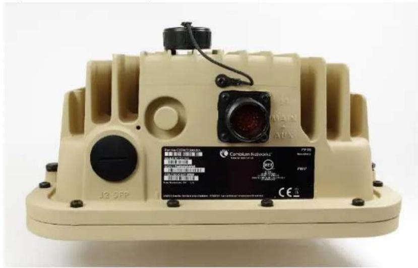
natural_image
Exterior view of a beige industrial device with camera lens and control buttons (no readable text or symbols)Table 18 Ethernet interfaces PTP 45700 ODU
| Port name | Connector | Interface | Description |
| Main PSU | RJ45 | POE input | Proprietary power over Ethernet (POE). |
| 100/1000BASE-T Ethernet | Management and/or data. | ||
| AUX | RJ45 | 100/1000BASE-T Ethernet with 802.3at compliant POE out capability | Auxiliary Ethernet port which can be used, for example, to connect and power a video camera or wireless access point. Data and Management Services. |
| SFP | SFP | Optical or Copper Gigabit Ethernet | Data and Management Services. Plug-in SFP module must be purchased separately. |
Table 19 Ethernet interfaces PTP 78700 ODU
| Port name | Connector | Interface | Description |
| Main PSU | 38999 (J1) | POE input | Proprietary power over Ethernet (POE). |
| 100/1000BASE-T Ethernet | Management and/or data. | ||
| AUX | 38999 (J1) | 100/1000BASE-T Ethernet with 802.3at compliant POE out capability | Auxiliary Ethernet port which can be used, for example, to connect and power a video camera or wireless access point. Data and Management Services. |
| SFP | SFP (J2) | Optical or Copper Gigabit Ethernet | Data and Management Services. Plug-in SFP module must be purchased separately. |
The front of the Connectorized or Connectorized+Integrated ODU (Figure 24, Figure 25 and Figure 26) provides N type female connectors for RF cable interfaces to antennas with horizontal (H) and vertical (V) polarization.
Figure 24 PTP 45700 Connectorized ODU antenna interfaces

natural_image
Close-up of a white electronic device housing with multiple connectors and ports (no visible text or symbols)Figure 25 PTP 45700 Connectorized+Integrated ODU antenna interfaces

natural_image
Close-up of a white plastic electrical connector with metallic connectors and metal fittings (no text or symbols visible)Figure 26 PTP 78700 Connectorized ODU antenna interfaces

natural_image
Close-up of two black earbuds with ear tags on a beige plastic tray (no text or symbols visible)ODU mechanical specifications
The PTP 700 ODU conforms to the specifications listed in Table 20.
Table 20 ODU specifications
| Category | Specification | |
| Dimensions | PTP 45700 Connectorized+Integrated | 371 mm (14.6 in) x 430 mm (16.9 in) x 98 mm (3.9 in) |
| PTP 45700 Connectorized | 204 mm (8.0 in) x 318 mm (12.5 in) x 98 mm (3.9 in) | |
| PTP 45700 Beam Steering | 581 mm (22.9 in) x 595 mm (23.4 in) x 84 mm (3.3 in) | |
| PTP 78700 Integrated | 401 mm (15.7 in) x 459 mm (18.1 in) x 146 mm (5.7 in) | |
| PTP 78700 Connectorized | 234 mm (9.2 in) x 348 mm (13.7 in) x 140 mm (5.5 in) | |
| Weight | PTP 45700 Connectorized+Integrated | 4.1 kg (9.0 lbs) excluding bracket |
| PTP 45700 Connectorized | 3.1 kg (6.8 lbs) including bracket | |
| PTP 45700 Beam Steering | 9.1 kg (20.1 lbs) including bracket | |
| PTP 78700 Integrated | 9.3 kg (20.4 lbs) including bracket | |
| PTP 78700 Connectorized | 7.1 kg (15.8 lbs) including bracket | |
| Temperature | -40°C (-40°F) to +60°C (140°F) | |
| Wind loading | PTP 45700 Connectorized+IntegratedPTP 45700 Connectorized | 200 mph (323 kph) maximum. |
| PTP 45700 Beam Steering | ||
| PTP 78700 Integrated | ||
| PTP 78700 Connectorized | ||
| PTP 45700 Beam Steering | 160 mph (257 kph) maximum. | |
| See ODU wind loading on page 3-13. | ||
| Humidity | 100% condensing | |
| Liquid and particle ingress | IP66, IP67 | |
| UV exposure | 10 year operational life (UL746C test evidence) | |
| Static discharge | See Electromagnetic compatibility (EMC) compliance on page 4-2 | |
Power supply units (PSU)
AC+DC Enhanced Power Injector 56V
PSU description
The AC+DC Enhanced Power Injector 56V PSU (Figure 27) is an indoor unit that is connected to the ODU and network terminating equipment using Cat5e cable with RJ45 connectors. It supplies a single ODU, accepts both AC and DC input, and allows the ODU to support a device on the Aux port, such as a video camera or wireless access point. It also allows the ODU to provide DC power output.
The AC+DC Power Injector 56V is approved for use with the PTP 45700 and PTP 78700 frequency variants of the ODU.
Figure 27 AC+DC Enhanced Power Injector 56V




Warning Always use an appropriately rated and approved AC supply cord-set in accordance with the regulations of the country of use.
Attention The PSU ODU ports are designed to connect only to PTP 700 ODUs, PTP-SYNC units, or LPUs. Do not connect any other equipment, as damage may occur. Do not connect the PIDU Plus PTP 300/500/600 Series to the PTP 700 ODU or LPU.
Note Each of the ODU kits listed in Table 7 includes one PSU and one US or EU line cord as stated in the Cambium description.
PSU part numbers
Order PSUs and (for AC power) line cords from Cambium Networks (Table 21).
Table 21 Power supply component part numbers
| Cambium description | Cambium part number |
| AC+DC Enhanced Power Injector 56V | C000065L002C, C000065L002D |
| US Line Cord Fig 8 | N000065L003A |
| UK Line Cord Fig 8 | N000065L004A |
| EU Line Cord Fig 8 | N000065L005A |
| Australia Line Cord Fig 8 | N000065L006A |
AC+DC Enhanced Power Injector 56V interfaces
The AC+DC Enhanced Power Injector 56V interfaces are shown in Figure 28 and described in Table 22.
Figure 28 AC+DC Enhanced Power Injector 56V interfaces

Table 22 AC+DC Enhanced Power Injector 56V interface functions
| Interface | Function |
| AC power input | Main AC supply. 100-240V 47-63Hz 1.5A |
| DC In | Alternative DC power supply input. |
| DC Out | DC power output to a second PSU (for power supply redundancy). |
| ODU port | RJ45 socket for connecting Cat5e cable to ODU. |
| LAN port | RJ45 socket for connecting Cat5e cable to network. |
| DC Power In (green) LED | DC Power supply detection |
| AC Power In (green) LED | AC Power supply detection |
| Ethernet (yellow) LED | Ethernet traffic detection |
PSU specifications
The AC+DC Enhanced Power Injector 56V conforms to the specifications listed in Table 23.
Table 23 AC+DC Enhanced Power Injector 56V specifications
| Category | Specification |
| Dimensions | 250 mm (9.75 in) x 40 mm (1.5 in) x 80 mm (3 in) |
| Weight | 0.864 Kg (1.9 lbs) |
| Temperature | -40°C (-40°F) to +60°C (140°F) |
| Humidity | 0 to 90% non-condensing |
| Waterproofing | Not waterproof |
| AC Input | 90-264 V AC, 47-60 Hz |
| Alternative DC Input | 37-60 V DC |
| DC Output Voltage | For mains input: 58 V, +2V, -0VFor DC input: Output voltage at maximum rated output current, not more than 1.5 V below the DC input voltage.Maximum length of DC output cable: 3 meters. |
| AC Input connector | IEC-320-C8 |
| DC Output current | 1.7A |
| Efficiency | Better than 84% |
| Over Current Protection | Hiccup current limiting, trip point set between 120% to 150% of full load current |
| Hold up time | At least 20 milliseconds |
| Power factor | Better than 0.9 |
Further reading
| For information about... | Refer to... |
| General description of TDD Synchronization | TDD synchronization on page 1-21 |
Antennas and antenna cabling
Antenna requirements
Each connectorized ODU requires one external antenna (normally dual-polarized), or if spatial diversity is required, each ODU requires two antennas.

Note To determine when to install connectorized units and to calculate their impact on link performance and regulatory limits, see Planning for connectorized units on page 3-30.
RF cable and connectors
RF cable of generic type LMR-400 is required for connecting the ODU to the antenna. N type male connectors are required for connecting the RF cables to the connectorized ODU. Two connectors are required per ODU. Use weatherproof connectors, preferably ones that are supplied with adhesive lined heat shrink sleeves that are fitted over the interface between the cable and connector. Order CNT-400 RF cable and N type male connectors from Cambium Networks (Table 24).
Table 24 RF cable and connector part numbers
| Cambium description | Cambium part number |
| 50 Ohm Braided Coaxial Cable - 75 meter | 30010194001 |
| 50 Ohm Braided Coaxial Cable - 500 meter | 30010195001 |
| RF Connector, N, Male, Straight for CNT-400 Cable | 09010091001 |

Note To select the correct connectors for the antenna end of the RF cable, refer to the antenna manufacturer's instructions.
Antenna accessories
Connectorized ODUs require the following additional components:
- Cable grounding kits: Order one cable grounding kit for each grounding point on the antenna cables. Refer to Lightning protection unit (LPU) and grounding kit on page 2-30 for specifications and part numbers.
- Self-amalgamating and PVC tape: Order these items to weatherproof the RF connectors.
- Lightning arrestors: When the connectorized ODU is mounted indoors, lightning arrestors (not PTP 700 LPUs) are required for protecting the antenna RF cables at building entry. One arrestor is required per antenna cable. One example of a compatible lightning arrestor is the Polyphaser LSXL-ME or LSXL (not supplied by Cambium Networks).
RF Combiner Kit
The RF Combiner Kit includes two RF Combiners together with mounting brackets for a standard pole or tower standoff. Use one RF Combiner Kit for each end of a Hot Standby (1+1) or 2+0 link where two PTP 78700 Connectorized ODUs are connected to a shared dual-polarized antenna.
The RF Combiner is shown in Figure 29.
Figure 29 RF Combiner

natural_image
White electronic device with three metallic connectors and a circular logo on top, against a black background (no readable text or symbols)The assembly of two RF Combiners on the supplied brackets is shown in Figure 30.
Figure 30 RF Combiner Kit assembled
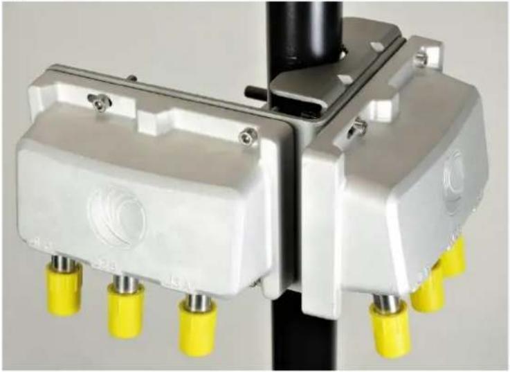
natural_image
Close-up of two white industrial sensors mounted on a black vertical pole with yellow connectors, no visible text or symbols.Order one kit for each end of the link.
Table 25 RF Combiner part numbers
| Cambium description | Cambium part number |
| PTP 700 2-way RF Combiner Kit | N000070L123A |
RF Combiner specifications
The table below shows the specification for a single RF Combiner.
Table 26 RF Combiner specifications
| Category | Specification |
| Dimensions | 150 mm (5.9 in) × 100 mm (3.9 in) × 55 mm (2.2 in) |
| Weight | 0.75 kg (1.7 lbs) |
| Temperature | -40°C (-40°F) to 60°C (140°F) |
| Humidity | 0 to 100%, condensing |
| Liquid and particle ingress | IP66, IP67 |
| RF connector | N-type |
| Frequency range | 4.4 GHz to 8.5 GHz |
| Typical insertion loss, 4.4 GHz to 6.8 GHz | J1P to J3A: 4.4 dB, J2S to J3A: 4.4 dB |
| Typical insertion loss, 6.8 GHz to 8.5 GHz | J1P to J3A: 4.7 dB, J2S to J3A: 4.7 dB |
| Minimum isolation | J1P to J2S: 24 dB |
Ethernet cabling
Ethernet standards and cable lengths
All configurations require a copper Ethernet connection from the ODU (PSU port) to the PSU. Advanced configurations may also require one or both of the following:
• A copper Ethernet connection from the ODU (Aux port) to an auxiliary device.
- An optical or copper Ethernet connection from the ODU (SFP port) to network terminating equipment or a linked ODU.
Table 27 and Table 28 specify, for each type of PSU and power supply, the maximum permitted PSU drop cable length.
Table 29 specifies, for Aux and copper SFP interfaces, the Ethernet standards supported and the maximum permitted drop cable lengths.

Note For optical SFP interfaces, refer to SFP module kits on page 2-33 for details of the Ethernet standards supported and maximum permitted cable lengths.
Table 27 PSU drop cable length restrictions for PTP 45700 ODU
| Type of PSU installed | Power supply to PSU | Ethernet supported | Power output to auxiliary device | Maximum cable length (*1) |
| AC+DC Enhanced Power Injector 56V | AC mains | No (*2) | No | 250 m (820 ft) |
| 56 V dc | No (*2) | No | 250 m (820 ft) | |
| AC mains | 100BASE-TX 1000BASE-T | Yes | 100 m (330 ft) | |
| 56 V dc | 100BASE-TX 1000BASE-T | Yes | 100 m (330 ft) |
(*1) Maximum length of Cat 5E Ethernet cable from ODU to network terminating equipment via PSU.
(*2) Ethernet is provided via optical SFP interface.
Table 28 PSU drop cable length restrictions for PTP 78700 ODU
| Type of PSU installed | Power supply to PSU | Ethernet supported | Power output to auxiliary device | Maximum cable length (*1) |
| AC+DC Enhanced Power Injector 56V | AC mains | No (*2) | No | 150 m (490 ft) |
| 56 V dc | No (*2) | No | 150 m (490 ft) | |
| AC mains | 100BASE-TX 1000BASE-T | Yes | 100 m (330 ft) | |
| 56 V dc | 100BASE-TX 1000BASE-T | Yes | 100 m (330 ft) |
(*1) Maximum length of Cat 5E Ethernet cable from ODU to network terminating equipment via PSU.
(*2) Ethernet is provided via optical SFP interface.
Table 29 Aux and copper SFP Ethernet standards and cable length restrictions
| ODU drop cable | Power over Ethernet | Ethernet supported | Maximum cable length (*1) |
| Aux - auxiliary device | POE to auxiliary device | 100BASE-TX1000BASE-T | 100 m (330 ft) |
| None | 100BASE-TX | 100 m (330 ft) | |
| SFP (copper) - linked device | None | 100BASE-TX | 100 m (330 ft) |
(*1) Maximum length of Ethernet cable from the ODU to the linked device.
Outdoor copper Cat5e Ethernet cable
For copper Cat5e Ethernet connections from the ODU to the PSU, LPUs and other devices, use Cat5e cable that is gel-filled and shielded with copper-plated steel, for example Superior Essex EnduraGain OSP Armored Cat 5e. This is known as “drop cable” (Figure 31).

Attention Always use Cat5e cable that is gel-filled and shielded with copper-plated steel. Alternative types of drop cable are not supported by Cambium Networks for the PTP 700.
Order Superior Essex EnduraGain OSP Armored Cat 5e cable from Cambium Networks (Table 30). Other lengths of this cable are available from Superior Essex.
Figure 31 Outdoor drop cable

Table 30 Drop cable part numbers
| Cambium description | Cambium part number |
| 1000 ft Reel Outdoor Copper Clad CAT5e | WB3175 |
| 328 ft (100 m) Reel Outdoor Copper Clad CAT5e | WB3176 |
Cable grounding kit
Copper drop cable shields must be bonded to the grounding system in order to prevent lightning creating a potential difference between the structure and cable, which could cause arcing, resulting in fire risk and damage to equipment. Optical cables do not require grounding.
One grounding kit (Figure 32) is required for each grounding point on the PSU, Aux and copper SFP drop cables. Order cable grounding kits from Cambium Networks (Table 31).

Attention To provide adequate protection, all grounding cables must be a minimum size of 10 mm2 csa (8AWG), preferably 16 mm2 csa (6AWG), or 25 mm2 csa (4AWG).
Figure 32 Cable grounding kit

natural_image
Assorted electrical components including a black cable, metal clamps, and a rolled-up cable with tape (no visible text or symbols)Table 31 Cable grounding kit part numbers
| Cambium description | Cambium part number |
| Cable Grounding Kits For 1/4" And 3/8" Cable | 01010419001 |
Lightning protection unit (LPU) and grounding kit
PTP 700 LPUs provide transient voltage surge suppression for PTP 700 installations. Each PSU or Aux drop cable requires two LPUs, one near the ODU and the other near the linked device, usually at the building entry point (Table 32).
Table 32 LPU and grounding kit contents
| Lightning protection units (LPUs)LPU grounding point nuts and washers | ODU to top LPU drop cable (600 mm)EMC strain relief cable glands |
 |  |
| U-bolts, nuts and washers for mounting LPUs | ODU to top LPU ground cable (M6-M6) |
 | 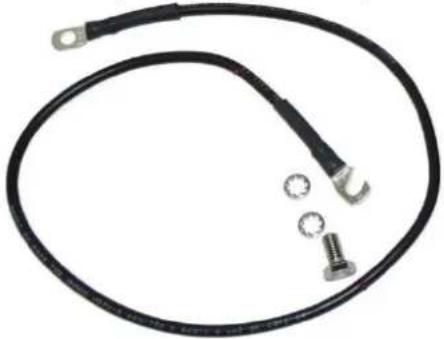 |
Bottom LPU ground cable (M6-M10)

natural_image
Black cable with three metal components and a separate screw, shown against a white background (no text or symbols)ODU to ground cable (M6-M10

natural_image
Coiled black electrical terminal with two metal terminals (no text or symbols visible)One LPU and grounding kit (Table 32) is required for the PSU drop cable connection to the ODU. If the ODU is to be connected to an auxiliary device, one additional LPU and grounding kit is required for the Aux drop cable. Order the kits from Cambium Networks (Table 33).
Table 33 LPU and grounding kit part number
| Cambium description | Cambium part number |
| LPU and Grounding Kit (One Kit Per End) | C000065L007 |

Note PTP 700 LPUs are not suitable for installation on SFP copper Cat5e Ethernet interfaces. For SFP drop cables, obtain suitable surge protectors from a specialist supplier.
SFP optical Ethernet interfaces do not require surge protectors.
LPU for GPS drop cables
When a GPS receiver is the timing reference source for PTP-SYNC (optional), an LPU must be installed near the point at which the GPS drop cable enters the building. A single LPU from the LPU and Grounding Kit (C000065L007) (Table 32) is suitable. Alternatively, the single LPU kit for PTP 250/300/500 (Figure 33) could be used.
Figure 33 LPU kit used for GPS receiver drop cables

Table 34 LPU and grounding kit part number - Use with GPS receiver drop cable only
| Cambium description | Cambium part number |
| LPU End Kit PTP 250/300/500 | WB2978 |
RJ45 connectors and spare glands
RJ45 connectors are required for plugging Cat5e cables into ODUs, LPUs, PSUs and other devices. Order RJ45 connectors and crimp tool from Cambium Networks (Table 35).

Note The RJ45 connectors and crimp tool listed in Table 35 work with Superior Essex EnduraGain OSP Armored Cat 5e cable (as supplied by Cambium Networks). They may not work with other types of cable.
The ODU is supplied with one environmental sealing gland for the drop cable. However, this is not suitable when surge protection is required: EMC glands must be used instead. EMC strain relief cable glands (quantity 5) are included in the LPU and grounding kit (Figure 34). These are identified with a black sealing nut. If extra glands are required, order them from Cambium Networks (in packs of 10) (Table 35).
One long EMC strain relief gland (Figure 37) is included in each SFP module kit. This is longer than the standard cable gland as it must house an SFP module plugged into the ODU.
Figure 34 Cable gland
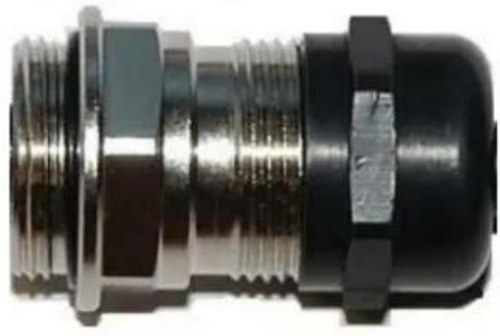
natural_image
Close-up of a metallic connector with threaded metal and black housing (no visible text or symbols)Table 35 RJ45 connector and spare gland part numbers
| Cambium description | Cambium part number |
| Tyco/AMP, Mod Plug RJ45 Unscreened, 100 pack | WB3177 |
| Tyco/AMP Crimp Tool | WB3211 |
| RJ-45 Spare Grounding Gland - PG16 size (Qty. 10) | N000065L033 |
Cable hoisting grip
One or more grips are required for hoisting the drop cable up to the ODU without damaging the gland or RJ45 plug (Figure 35). They are not supplied by Cambium Networks.
Figure 35 Cable hoisting grip

natural_image
Close-up of a metallic wire-wrapped tool or connector with coiled wires and metal connectors (no text or symbols visible)Indoor Cat5e cable
To connect the PSU to network terminating equipment, use indoor Cat5e cable. The ODU network connection implements automatic MDI/MDI-X sensing and pair swapping, allowing connection to networking equipment that requires cross-over cables (MDI-X networks) or straight-through cables (MDI Networks).
SFP module kits
SFP module kits allow connection of a PTP 700 Series ODU to a network over a Gigabit Ethernet interface in one of the following full-duplex modes:
• Optical Gigabit Ethernet: 1000BASE-LX or 1000BASE-SX
• Copper Gigabit Ethernet: 100BASE-TX or 1000BASE-T
Order SFP module kits from Cambium Networks (Table 36).
Table 36 SFP module kit part numbers
| Cambium description | Cambium part number |
| Single Mode Optical SFP Interface per ODU | C000065L008A |
| Multi-mode Optical SFP Interface per ODU | C000065L009A |
| Gig-Ethernet SFP Interface per ODU | C000065L010A |
To compare the capabilities of the two optical SFP modules, refer to Table 37 and Table 38.
Table 37 Single Mode Optical SFP Interface (part number C000065L008A)
| Core/ cladding (microns) | Mode | Bandwidth at 1310 nm (MHz/km) | Maximum length of optical interface | Insertion loss (dB) |
| 62.5/125 | Multi | 500 | 550 m (1800 ft) | 2.35 |
| 50/125 | Multi | 400 | 550 m (1800 ft) | 2.35 |
| 50/125 | Multi | 500 | 550 m (1800 ft) | 2.35 |
| 10/125 | Single | N/A | 5000 m (16400 ft) | 4.57 |
Table 38 Multi-mode Optical SFP Interface (part number C000065L009A)
| Core/ cladding (microns) | Mode | Bandwidth at 850 nm (MHz/km) | Maximum length of optical interface | Insertion loss (dB) |
| 62.5/125 | Multi | 160 | 220 m (720 ft) | 2.38 |
| 62.5/125 | Multi | 200 | 275 m (900 ft) | 2.6 |
| 50/125 | Multi | 400 | 500 m (1640 ft) | 3.37 |
| 50/125 | Multi | 500 | 550 m (1800 ft) | 3.56 |
The upgrade kits contain the following components:
• Optical or copper SFP transceiver module (Figure 36)
• Long EMC strain relief cable gland (Figure 37)
• The Ethernet SFP Module Installation Guide
- License key instructions and unique Access Key
Figure 36 Optical or copper SFP transceiver module

Figure 37 Long cable gland

natural_image
Close-up of a metallic cylindrical connector with threaded ends and black housing (no visible text or symbols)
Note PTP 700 does not support the Synchronous Ethernet or 1588 Transparent Clock features using copper SFP transceivers.
Optical cable and connectors
Order an optical cable with LC connectors from a specialist fabricator, quoting the specification shown in Figure 38. It must be the correct length to connect the ODU to the other device. LC connectors should be supplied with dust caps to prevent dust build up.
Figure 38 Optical optic cable and connector specification
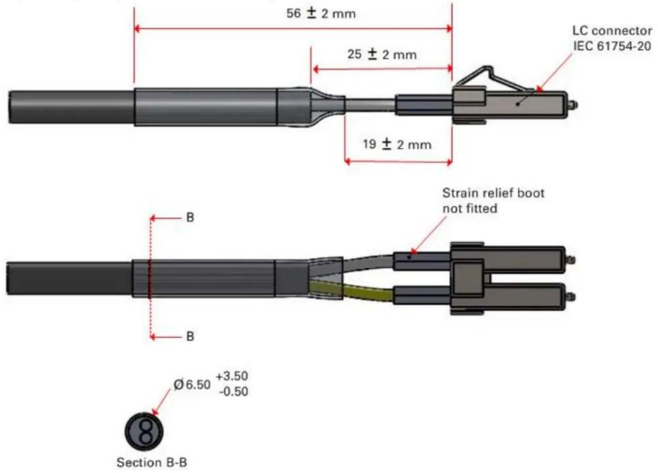
PTP-SYNC unit

Note The PTP-SYNC unit is not supported for TDD synchronization with PTP 78700 (7125-8500 MHz) ODUs. For these ODUs, use an alternative synchronization source.
PTP-SYNC unit description
The PTP-SYNC unit is an optional component, used to synchronize the ODU TDD frame with a network-wide reference. It measures the difference between the TDD frame timing and a 1 Hz timing reference, and signals this time difference to the ODU. For more information on this feature, refer to TDD synchronization on page 1-21.
The PTP-SYNC unit is a compact indoor unit mounted on a wall, shelf or (using an optional rack mounting adaptor) in a standard 19 inch rack (Figure 40).
The PTP-SYNC unit is connected in line in the drop cable between the AC+DC Power Injector 56V and the ODU, and is collocated with the AC+DC Power Injector 56V. The PTP-SYNC draws power from the drop cable, and does not require a separate power supply.

Attention The PTP-SYNC is compatible only with the AC+DC Power Injector 56V. PTP-SYNC is not compatible with standards-based power-over-Ethernet (PoE).
Figure 39 PTP-SYNC kit
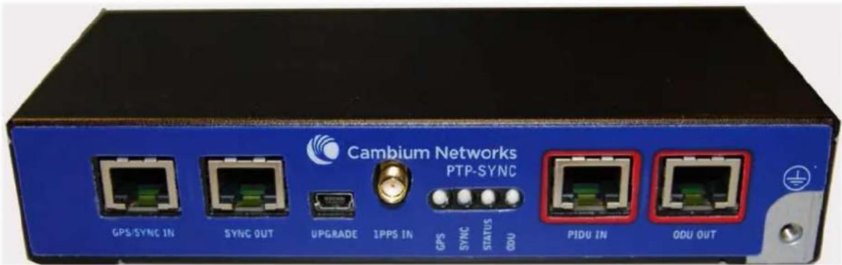
Figure 40 PTP-SYNC rack mounting adapter
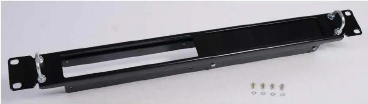
natural_image
Black metal mechanical bracket with mounting holes and a series of small metallic pins (no text or symbols visible)PTP-SYNC part numbers
Order PTP-SYNC kits and associated components from Cambium Networks (Table 39).
Table 39 PTP-SYNC component part numbers
| Cambium description | Cambium part number |
| PTP-SYNC kit | WB3665 |
| CMU/PTP-SYNC/NIDU 19inch Rack Mount Installation Kit | WB3486 |
The PTP-SYNC kit contains:
- 1 x PTP-SYNC unit
- 1 x M4 pan screw
- 2 x M4 washers
- 2 x M3 (6mm) torx drive screws
- 1 x lug for unit ground (cable not supplied)
- 1 x Cat5e cable (length 1 meter)
- Installation guide
If the 1 meter Cat5e cable supplied with the PTP-SYNC kit is not long enough, order a longer length of Cat5e cable, up to 2 meters long.
The PTP-SYNC rack mount kit contains:
- 1 x rack bracket
- 8 x M3 washers
- 8 x M3 screws
- 1 x rack mount blank plate
- 8 x M5 nuts
- 8 x M5 washers
- 2 x rack handles
PTP-SYNC unit interfaces
The PTP-SYNC front panel is illustrated in Figure 41. The annotated interfaces are described in Table 40 and Table 41.
Figure 41 PTP-SYNC front panel

Table 40 PTP-SYNC interface functions
| # | Description | Function |
| 1 | GPS/SYNC IN | Input from GPS receiver or from the daisy-chained SYNC OUT signal of another PTP-SYNC. |
| 2 | SYNC OUT | Output to daisy-chained PTP-SYNC units. |
| 3 | USB | Input for firmware upgrades. Contact Cambium for instructions. |
| 4 | 1PPS IN | Coaxial alternative to GPS/SYNC IN. Peak input voltage must not exceed 5 V. |
| 5 | LED bank | LEDs and their functions are described in Table 41. |
| 6 | PIDU IN | Input from PSU. |
| 7 | ODU OUT | Output to ODU. |
| 8 | Ground stud | For connecting to a ground point. |
Table 41 PTP-SYNC LED functions
| LED | Function |
| GPS | GPS satellite data detection. |
| SYNC | SYNC OUT port data detection. |
| STATUS | Power and satellite lock detection. |
| ODU | ODU signal detection. |
For a full list of LED states and fault-finding actions, refer to Testing PTP-SYNC on page 8-15.
PTP-SYNC specifications
The PTP-SYNC unit conforms to the specifications listed in Table 42, Table 43 and Table 44.
Table 42 PTP-SYNC unit physical specifications
| Category | Specification |
| Dimensions | Width excluding ears 174 mm (6.69 in) |
| Width including ears 196 mm (7.54 in) | |
| Height 31.5 mm (1.21 in) | |
| Depth 79 mm (3.04 in) | |
| Weight | 0.485 Kg (1.1 lbs) |
Table 43 PTP-SYNC unit environmental specifications
| Category | Specification |
| Temperature | -40°C (-40°F) to +60°C (140°F)Suitable for use indoors, or outdoors within a weatherproofed cabinet. |
| Humidity | 0 to 95% non-condensing |
| Waterproofing | Not waterproof |
Table 44 PTP-SYNC unit electrical specifications
| Category | Specification |
| Power supply | Integrated with PSU |
| Power consumption | 1.5 W max (extra power is required to supply a GPS receiver) |
There are two timing inputs to the PTP-SYNC unit: GPS/SYNC IN (RJ-45) (Table 45) and 1PPS IN (SMA) (Table 46).
Table 45 PTP-SYNC unit timing specifications - GPS/SYNC IN (RJ-45)
| Category | Specification |
| Signal type | Differential 1 Hz signal |
| Common mode range | -7 V to +7 V, relative to GPS/SYNC IN pin 2 (ground) |
| Maximum differential voltage | 35 V |
| Threshold | 30.4 V |
| Impedance | 90 ohms to 110 ohms |
| Pulse width | 1 μs to 500 ms |
| Polarity | Reference edge is when pin 3 (PPSA) is positive with respect to pin 6 (PPSB) |
Table 46 PTP-SYNC unit timing specifications - 1PPS IN (SMA)
| Category | Specification |
| Signal type | 1 Hz signal |
| Pulse | Positive pulse, reference edge is rising edge |
| Maximum voltage | 5 V |
| Threshold | 0.4 V to 0.6 V |
| Input impedance | 45 ohms to 55 ohms |
| Pulse width | 1µs to 500ms |
The pinouts of the PTP-SYNC unit GPS/SYNC IN port are specified in Table 47.
Table 47 GPS/SYNC IN port pinouts
| Pin no. | Connector pinout signal name | Signal description |
| Pin 1 | 12VGPS | 12 V output to GPS receiver module, 250 mA max |
| Pin 2 | GND | Ground |
| Pin 3 | GPS_1PPSA | 1 Hz pulse input |
| Pin 4 | GPS_RXDA | GPS receive data |
| Pin 5 | GPS_RXDB | GPS receive data |
| Pin 6 | GPS_1PPSB | 1 Hz pulse input |
| Pin 7 | GPS_TXDA | GPS transmit data |
| Pin 8 | GPS_TXDB | GPS transmit data |

Note The GPS_1PPS, GPS_RXD and GPS_TXD signals conform to International Telecommunication Union (ITU) recommendation V.11 (RS422)
Signal polarities
A 1 PPS timing datum is detected when GPS_1PPSA goes positive relative to GPS_1PPSB. A serial data start bit is detected when GPS_RXDA (or GPS_TXDA) goes positive relative to GPS_RXDB (or GPS_TXDB).
GPS receivers
Trimble Acutime™ GG GPS receiver for PTP-SYNC

Note The PTP-SYNC unit is not supported for TDD synchronization with PTP 78700 (7125-8500 MHz) ODUs. For these ODUs, use an alternative synchronization source.
The GPS receiver (Figure 42) is an optional timing reference source for PTP-SYNC. It provides a 1 Hz signal, accurately synchronized in frequency and phase across the network.
Figure 42 GPS receiver

natural_image
White dome-shaped security helmet with internal components, set against an orange background (no text or symbols visible)The GPS receiver is supplier with a GPS adapter cable kit (Figure 43). This avoids the need to fit a 12 way circular connector to the GPS drop cable. The kit contains one adapter cable (GPS receiver circular connector to RJ45 socket) and one RJ45 plug housing.
Figure 43 GPS adapter cable kit

natural_image
Black plastic electrical connector with attached cable and multiple connectors (no text or symbols visible)GPS receiver part numbers
Order GPS receivers and associated components from Cambium Networks (Table 48).
Table 48 GPS receiver component part numbers
| Cambium description | Cambium part number |
| Trimble AcutimeTMGG GPS receiver | WB4141 |
| PTP-SYNC <-> Trimble Adapter Cable (*1) | WB3961 |
| 1000 ft Reel Outdoor Copper Clad CAT5E (*2) | WB3175 |
| 328 ft (100 m) Reel Outdoor Copper Clad CAT5E (*2) | WB3176 |
| Tyco/AMP, Mod Plug RJ45 Unscreened, 100 pack (*3) | WB3177 |
| Tyco/AMP Crimp Tool (*3) | WB3211 |
| Cable Grounding Kits For 1/4" And 3/8" Cable (*4) | 01010419001 |
| LPU End Kit PTP 250/300/500 (*5) | WB2978D |
(*1) This adapter cable is included with the GPS receiver (part number WB4141).
(*2) Other lengths of this EnduraGain OSP Armored Cat 5e drop cable are available from Superior Essex.
(*3) The RJ45 connectors and crimp tool only work with Superior Essex EnduraGain OSP Armored Cat 5e cable.
(*4) One grounding kit is required per drop cable grounding point.
(*5) One LPU kit is required per GPS receiver.
Twelve way circular connector
As an alternative to the GPS adapter cable, the drop cable can be connected directly to the GPS unit via a 12 way circular connector, using the components and tools listed in Table 49.
Table 49 Recommended outdoor connectors for Trimble GPS receiver
| Item | Manufacturer | Part number |
| 12 way circular connector | Deutsch | IMC26-2212X |
| Size 22 crimp socket | Deutsch | 6862-201-22278 |
| Crimp tool | Daniels Manufacturing Corp | MH860 |
| Positioner | Daniels Manufacturing Corp | 86-5 |
| Insertion / extraction tool | Deutsch | 6757-201-2201 |
| Adaptor | Deutsch | IMC2AD |
| Self amalgamating tape |
This chapter provides information to help the user to plan a PTP 700 link.
The following topics are described in this chapter:
- Typical deployment on page 3-2 contains diagrams illustrating typical PTP 700 site deployments.
- Site planning on page 3-10 describes factors to be considered when planning the proposed link end sites, including grounding, lightning protection and equipment location.
- Radio spectrum planning on page 3-20 describes how to plan PTP 700 links to conform to the regulatory restrictions that apply in the country of operation.
- Link planning on page 3-24 describes factors to be taken into account when planning links, such as range, path loss and throughput.
- Planning for connectorized units on page 3-30 describes factors to be taken into account when planning to use connectorized ODUs with external antennas in PTP 700 links.
- Configuration options for TDD synchronization on page 3-36 describes the different configuration options that may be used for implementing TDD synchronization in the PTP 700 Series.
- Data network planning on page 3-47 describes factors to be considered when planning PTP 700 data networks. This section describes various services provided for Ethernet traffic; these are: Data Service, Management Service, Local Management Service, Protection Service, TD-90 Service.
- Network management planning on page 3-57 describes how to plan for PTP 700 links to be managed remotely using SNMP.
- Security planning on page 3-68 describes how to plan for PTP 700 links to operate in secure mode.
- System threshold, output power and link loss on page 3-82 contains tables that specify the system threshold (dBm), output power (dBm) and maximum link loss (dB) per channel bandwidth and modulation mode.
- Data throughput capacity tables on page 3-112 contains tables and graphs to support calculation of the data rate capacity that can be provided by PTP 700 configurations.
Typical deployment
This section contains diagrams illustrating typical PTP 700 site deployments.
ODU with POE interface to PSU
In the basic configuration, there is only one Ethernet interface, a copper Cat5e power over Ethernet (POE) from the PSU to the ODU (PSU port), as shown in the following diagrams: mast or tower installation (Figure 44), wall installation (Figure 45) and roof installation (Figure 46).
Figure 44 Mast or tower installation

flowchart
graph TD
    A["Power over Ethernet CAT5e cable (gel-filled, shielded with copper-plated steel)"] --> B["Network CAT5e cable"]
    B --> C["PTP 700 ground cables"]
    C --> D["Site grounding system"]
    D --> E["Top LPU"]
    E --> F["ODU"]
    G["Equipment building or cabinet"] --> H["Bottom LPU"]
    H --> I["PSU"]
    I --> J["AC supply"]
    J --> K["Network equipment"]
    K --> L["Building entry"]
    L --> M["Tower ground bar"]
    M --> N["Intermediate ground cable(s) as required"]
    N --> O["Ground ring"]
Figure 45 Wall installation

flowchart
graph TD
    A["Power over Ethernet CAT5e cable (gel-filled, shielded with copper-plated steel)"] --> B["Network Cat5e cable"]
    B --> C["PTP 700 ground cables"]
    C --> D["Site grounding system"]
    E["Top LPU"] --> F["ODU"]
    G["Bottom LPU"] --> H["PSU"]
    I["Building entry"] --> J["AC supply"]
    K["Ground ring"] --> L["Network equipment"]
Figure 46 Roof installation
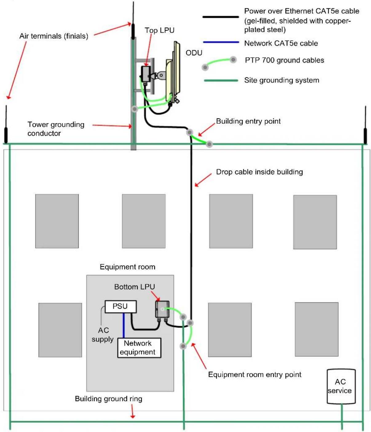
flowchart
graph TD
    A["Power over Ethernet CAT5e cable (gel-filled, shielded with copper-plated steel)"] --> B["Network CAT5e cable"]
    B --> C["PTP 700 ground cables"]
    C --> D["Site grounding system"]
    E["Air terminals (finials)"] --> F["Tower grounding conductor"]
    F --> G["Building entry point"]
    G --> H["Drop cable inside building"]
    I["Equipment room"] --> J["Bottom LPU"]
    J --> K["PSU"]
    K --> L["AC supply"]
    L --> M["Network equipment"]
    M --> N["Building ground ring"]
    O["Equipment room entry point"] --> P["AC service"]
SFP and Aux Ethernet interfaces
There may be one or two additional Ethernet interfaces connected to the ODU: one to the SFP port (copper or optical) and one to the Aux port, as shown in the following diagrams:
• ODU with copper SFP and PSU interfaces - Figure 47
• ODU with optical SFP and PSU interfaces - Figure 48
• ODU with Aux and PSU interfaces - Figure 49
Figure 47 ODU with copper SFP and PSU interfaces
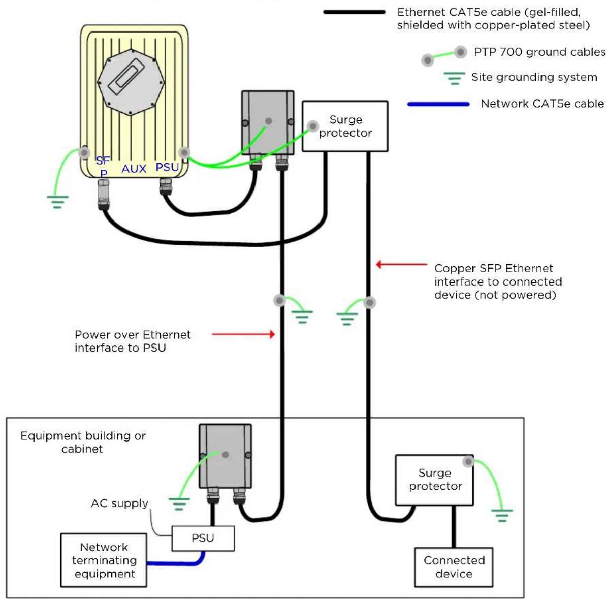
flowchart
graph TD
    A["Power over Ethernet interface to PSU"] --> B["Surge protector"]
    B --> C["Network CAT5e cable (gel-filled, shielded with copper-plated steel)"]
    B --> D["Copper SFP Ethernet interface to connected device (not powered)"]
    D --> E["Connected device"]
    F["Network terminating equipment"] --> G["AC supply"]
    G --> H["Equipment building or cabinet"]
    H --> I["PSU"]
    I --> J["Power over Ethernet interface to PSU"]
    K["SPP AUX PSU"] --> L["PGS"]
    M["PGS"] --> N["PGS"]
    O["PGS"] --> P["PGS"]
    Q["PGS"] --> R["PGS"]
    S["PGS"] --> T["PGS"]
    U["PGS"] --> V["PGS"]
    W["PGS"] --> X["PGS"]
    Y["PGS"] --> Z["PGS"]
    AA["PGS"] --> AB["PGS"]
    AC["PGS"] --> AD["PGS"]
    AE["PGS"] --> AF["PGS"]
Figure 48 ODU with optical SFP and PSU interfaces

flowchart
graph TD
    A["Connected device"] --> B["SFP AUX PSU"]
    B --> C["PSU"]
    C --> D["Network terminating equipment"]
    D --> E["AC supply"]
    E --> F["Equipment building or cabinet"]
    G["Ethernet optical cable"] --> H["Optical cable"]
    I["Ethernet CAT5e cable (gel-filled, shielded with copper-plated steel)"] --> J["Power over Ethernet interface to PSU"]
    K["PTP 700 ground cables"] --> L["Site grounding system"]
    M["Network CAT5e cable"] --> N["Power over Ethernet interface to PSU"]
Figure 49 ODU with Aux and PSU interfaces

flowchart
graph TD
    A["SFP AUX PSU"] --> B["Power over Ethernet interface to PSU"]
    B --> C["Equipment building or cabinet"]
    C --> D["AC supply"]
    D --> E["PSU"]
    E --> F["Network terminating equipment"]
    G["Auxiliary device"] --> H["Ethernet interface (with optional power) to auxiliary device"]
    I["Ethernet CAT5e cable (gel-filled, shielded with copper-plated steel)"] --> J["PTP 700 ground cables"]
    J --> K["Site grounding system"]
    K --> L["Network CAT5e cable"]
GPS receiver interfaces
If a GPS receiver is deployed for PTP-SYNC, it may be mounted on the wall of the equipment building (Figure 50) (preferred option), or on a metal tower or mast (Figure 51).
Figure 50 GPS receiver wall installation

flowchart
graph TD
    A["Power over Ethernet CAT5e cable (gel-filled, shielded with copper-plated steel)"] --> B["Network Cat5e cable"]
    B --> C["PTP 700 ground cables"]
    C --> D["Site grounding system"]
    D --> E["GPS receiver"]
    E --> F["First point of contact between drop cable and wall"]
    F --> G["Drop cable to top LPU and ODU"]
    H["AC+DC Power Injector"] --> I["PSU"]
    I --> J["AC supply"]
    J --> K["Network equipment"]
    K --> L["PTP-SYNC"]
    L --> M["Ground ring"]
    M --> N["Ground"]
Figure 51 GPS receiver tower or mast installation

flowchart
graph TD
    A["Power over Ethernet CAT5e cable (gel-filled, shielded with copper-plated steel)"] --> B["Network CAT5e cable"]
    B --> C["PTP 700 ground cables"]
    C --> D["Site grounding system"]
    D --> E["GPS receiver"]
    E --> F["First point of contact between drop cable and tower"]
    F --> G["Intermediate ground cable(s) as required"]
    G --> H["Tower ground bar"]
    H --> I["Ground ring"]
    I --> J["AC+DC Power Injector"]
    I --> K["PSU"]
    I --> L["Network equipment"]
    I --> M["AC supply"]
    I --> N["Drop cable to top LPU and ODU"]
    I --> O["Equipment building or cabinet"]
Site planning
This section describes factors to be considered when planning the proposed link end sites, including grounding, lightning protection and equipment location for the ODU, PSU, PTP-SYNC unit (if installed) and GPS receivers (if installed).
Grounding and lightning protection

Warning Electro-magnetic discharge (lightning) damage is not covered under warranty. The recommendations in this guide, when followed correctly, give the user the best protection from the harmful effects of EMD. However, 100% protection is neither implied nor possible.
Structures, equipment and people must be protected against power surges (typically caused by lightning) by conducting the surge current to ground via a separate preferential solid path. The actual degree of protection required depends on local conditions and applicable local regulations. To adequately protect a PTP 700 installation, both ground bonding and transient voltage surge suppression are required.
Full details of lightning protection methods and requirements can be found in the international standards IEC 61024-1 and IEC 61312-1, the U.S. National Electric Code ANSI/NFPA No. 70-1984 or section 54 of the Canadian Electric Code.

Note International and national standards take precedence over the requirements in this guide.
Lightning protection zones
Use the rolling sphere method (Figure 52) to determine where it is safe to mount equipment. An imaginary sphere, typically 50 meters in radius, is rolled over the structure. Where the sphere rests against the ground and a strike termination device (such as a finial or ground bar), all the space under the sphere is considered to be in the zone of protection (Zone B). Similarly, where the sphere rests on two finials, the space under the sphere is considered to be in the zone of protection.
Figure 52 Rolling sphere method to determine the lightning protection zones
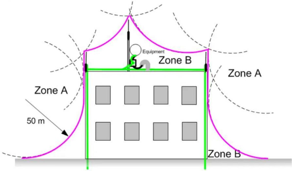
Zone A: In this zone a direct lightning strike is possible. Do not mount equipment in this zone.
Zone B: In this zone, direct EMD (lightning) effects are still possible, but mounting in this zone significantly reduces the possibility of a direct strike. Mount equipment in this zone.

Warning Never mount equipment in Zone A. Mounting in Zone A may put equipment, structures and life at risk.
Site grounding system
Confirm that the site has a correctly installed grounding system on a common ground ring with access points for grounding PTP 700 equipment.
If the outdoor equipment is to be installed on the roof of a high building (Figure 46), confirm that the following additional requirements are met:
- A grounding conductor is installed around the roof perimeter to form the main roof perimeter lightning protection ring.
- Air terminals are installed along the length of the main roof perimeter lightning protection ring, typically every 6.1m (20ft).
- The main roof perimeter lightning protection ring contains at least two down conductors connected to the grounding electrode system. The down conductors should be physically separated from one another, as far as practical.
ODU and external antenna location
Find a location for the ODU (and external antenna for connectorized units) that meets the following requirements:
- The equipment is high enough to achieve the best radio path.
- People can be kept a safe distance away from the equipment when it is radiating. The safe separation distances are defined in Calculated distances on page 4-4.
- The equipment is lower than the top of the supporting structure (tower, mast or building) or its lightning air terminal.
- If the ODU is connectorized, select a mounting position that gives it maximum protection from the elements, but still allows easy access for connecting and weatherproofing the cables. To minimize cable losses, select a position where the antenna cable lengths can be minimized. If diverse or two external antennas are being deployed, it is not necessary to mount the ODU at the midpoint of the antennas.
ODU ambient temperature limits
Select a location where the ODU can operate within safe ambient temperature limits.
The ODU must be mounted in a Restricted Access Location (as defined in EN 60950-1) if the operating ambient temperature may exceed 40irc C, including solar radiation.
If the ambient temperature never exceeds 40irc C, the temperature of the external metal case parts of the ODU will not exceed the touch temperature limit of 70irc C.
If the ambient temperature never exceeds 60irc C, the temperature of the external metal case parts of the ODU will not exceed the touch temperature limit of 90irc C.

Note A restricted access location is defined (in EN 60950-1) as one where access may only be gained by use of a tool or lock and key, or other means of security, and access is controlled by the authority responsible for the location. Access must only be gained by persons who have been instructed about the reasons for the restrictions applied to the location and about any precautions that must be taken. Examples of permissible restricted access locations are a lockable equipment room or a lockable cabinet.
ODU wind loading
Ensure that the ODU and the structure on which it is mounted are capable of withstanding the prevalent wind speeds at a proposed PTP 700 site. Wind speed statistics should be available from national meteorological offices.
The ODU and its mounting bracket are capable of withstanding wind speeds of up to 325 kph (200 mph), with the exception of the Beam Steering ODU, which is capable of withstanding 257 kph (160 mph).
Wind blowing on the ODU will subject the mounting structure to significant lateral force. The magnitude of the force depends on both wind strength and the variant of the ODU. Wind loading is estimated using the following formulae:
• Force (in newtons) = 0.5 × ρ × V2 × A × Cd
- “ρ” is the density of air = 1.225 kg/m 3 ,
• "V" is the wind speed in meters per second, - “A” is the projected surface area of the ODU in square meters, and
- “C d ” is the drag coefficient = 1.385.
The drag coefficient has been measured when the cover plate or antenna is perpendicular to the air flow.
Applying this formula to the PTP 700 ODUs at different wind speeds, the resulting wind loadings are shown in Table 50
Table 50 ODU wind loading (newtons)
| Type of ODU | Max surface area (square meters) | Wind speed (kilometers per hour) | ||||
| 225 | 250 | 275 | 300 | 325 | ||
| Connectorized+Integrated | 0.160 | 530 N | 655 N | 792 N | 943 N | 1106 N |
| Connectorized | 0.062 | 205 N | 254 N | 307 N | 365 N | 429 N |
| Beam Steering | 0.346 | 1147 N | 1415 N | - | - | - |
Equivalent results in US customary units are shown in Table 51.
Table 51 ODU wind loading (pounds force)
| Type of ODU | Max surface area (square feet) | Wind speed (miles per hour) | ||||
| 140 | 155 | 170 | 185 | 200 | ||
| Connectorized+Integrated | 1.72 | 120 lb | 147 lb | 176 lb | 209 lb | 244 lb |
| Connectorized | 0.67 | 46 lb | 57 lb | 68 lb | 81 lb | 95 lb |
| Beam Steering | 3.724 | 258 lb | 317 lb | - | - | - |
If an external antenna is installed, add the wind loading of the antenna to that of the ODU. The antenna manufacturer should be able to quote wind loading.
Hazardous locations
Check that the ODUs will not be exposed to hazardous gases, as defined by HAZLOC (USA) and ATEX (Europe) regulations.
PSU DC power supply
If using the DC input on the AC+DC Power Injector 56V, ensure that the DC power supply meets the following requirements:
- The voltage and polarity must be correct and must be applied to the correct PSU terminals.
- The power source must be rated as Safety Extra Low Voltage (SELV).
• The power source must be rated to supply at least 1.5A continuously. - The power source cannot provide more than the Energy Hazard Limit as defined by IEC/EN/UL60950-1, Clause 2.5, Limited Power (The Energy Hazard Limit is 240VA).
PSU AC power supply
Always use an appropriately rated and approved AC supply cord-set in accordance with the regulations of the country of use.
PSU location
Find a location for the PSU (AC+DC Enhanced Power Injector 56V) that meets the following requirements:
- The AC+DC Enhanced Power Injector 56V can be mounted on a wall or other flat surface.
• The PSU is kept dry, with no possibility of condensation, flooding or rising damp. - The PSU is located in an environment where it is not likely to exceed its operational temperature rating, allowing for natural convection cooling.
- The PSU can be connected to the ODU drop cable and network terminating equipment.
- The PSU can be connected to a compatible power supply. AC+DC Enhanced Power Injector 56V: the use of DC supplies of less than 55V will reduce the usable distance between the PSU and ODU.
PTP-SYNC location
If PTP-SYNC is to be installed, consider the following factors when selecting a site:
- Indoor location with no possibility of condensation.
- Accessibility for viewing status indicators.
• The maximum cable length between the PSU and the PTP-SYNC is 2 m (6 ft).
GPS receiver location
Mount the GPS receiver for PTP-SYNC at a location that meets the following requirements:
- It must be possible to protect the installation as described in Grounding and lightning protection on page 3-10.
- It must have an un-interrupted view of at least half of the sky. For a receiver mounted on a wall there must be no other significant obstructions in the view of the sky.
- It must be mounted at least 1 m (3 ft), preferably 2 m (6 ft), away from other GPS receiving equipment.
- It must not be sited in the field of radiation of co-located radio communications equipment and should be positioned at a distance of at least 3 m (10 ft) away.
Mount the GPS receiver on the wall of the equipment building, if there is a suitable location on the wall that can meet these requirements. Failing that, mount it on a metal tower or mast.

Attention The GPS receiver is not approved for operation in locations where gas hazards exist, as defined by HAZLOC (USA) and ATEX (Europe).
Mounting the GPS receiver module on the equipment building
If mounting the GPS receiver for PTP-SYNC on the equipment building (Figure 50), select a position on the wall that meets the following requirements:
- It must be below the roof height of the equipment building or below the height of any roof-mounted equipment (such as air conditioning plant).
- It must be below the lightning air terminals.
- It must not project more than 600mm (24 inches) from the wall of the building.
If these requirements cannot all be met, then the module must be mounted on a metal tower or mast.
Mounting the GPS receiver module on a metal tower or mast
If mounting the GPS receiver module on a metal tower or mast (Figure 51), select a position that meets the following requirements:
- It must not be mounted any higher than is necessary to receive an adequate signal from four GPS satellites.
- It must be protected by a nearby lightning air terminal that projects farther out from the tower than the GPS receiver module.
Drop cable grounding points
To estimate how many grounding kits are required for each drop cable, refer to the site installation diagrams (Figure 44, Figure 45 and Figure 46) and use the following criteria:
- The drop cable shield must be grounded near the ODU at the first point of contact between the drop cable and the mast, tower or building.
- The drop cable shield must be grounded at the building entry point.
For mast or tower installations (Figure 44), use the following additional criteria:
- The drop cable shield must be grounded at the bottom of the tower, near the vertical to horizontal transition point. This ground cable must be bonded to the tower or tower ground bus bar (TGB), if installed.
- If the tower is greater than 61 m (200 ft) in height, the drop cable shield must be grounded at the tower midpoint, and at additional points as necessary to reduce the distance between ground cables to 61 m (200 ft) or less.
- In high lightning-prone geographical areas, the drop cable shield must be grounded at spacing between 15 to 22 m (50 to 75 ft). This is especially important on towers taller than 45 m (150 ft).
For roof installations (Figure 46), use the following additional criteria:
- The drop cable shield must be bonded to the building grounding system at its top entry point (usually on the roof).
- The drop cable shield must be bonded to the building grounding system at the entry point to the equipment room.
LPU location
Find a location for the top LPU that meets the following requirements:
- There is room to mount the LPU, either on the ODU mounting bracket or on the mounting pole below the ODU.
• The drop cable length between the ODU and top LPU must not exceed 600 mm. - There is access to a metal grounding point to allow the ODU and top LPU to be bonded in the following ways: top LPU to ODU; ODU to grounding system.
Find a location for the bottom LPU that meets the following requirements:
- The bottom LPU can be connected to the drop cable from the ODU.
- The bottom LPU is within 600 mm (24 in) of the point at which the drop cable enters the building, enclosure or equipment room within a larger building.
- The bottom LPU can be bonded to the grounding system.
Multiple LPUs
If two or three drop cables are connected to the ODU, the PSU and Aux drop cables each require their own top LPU, and the copper SFP drop cable requires a top surge protector, not a PTP 700 LPU (Figure 53). Optical cables do not require LPUs or ground cables (Figure 54).
The copper SFP drop cable requires a bottom surge protector, not a PTP 700 LPU (Figure 55).
The Aux drop cable may require an LPU near the auxiliary device.
Figure 53 ODU with PSU, Aux and copper SFP interfaces

flowchart
graph TD
    A["ODU"] --> B["Grounding point for ODU"]
    A --> C["Copper SFP module"]
    A --> D["Com mon grounding point for top LPUs and surge protector"]
    A --> E["Auxiliary drop cable"]
    A --> F["Surge protector (not PTP 650 LPU)"]
    A --> G["Copper SFP drop cable"]
    B --> H["Grounding system"]
    C --> I["PSU drop cable"]
    D --> J["PGP"]
    E --> K["PGP"]
    F --> L["PGP"]
Figure 54 ODU with PSU, Aux and optical SFP interfaces
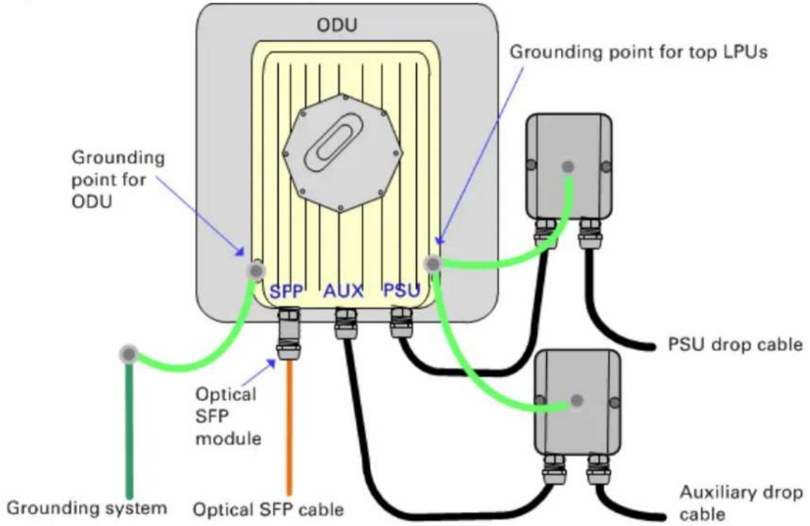
Figure 55 Bottom LPU and surge protector

flowchart
graph TD
    A["Connected device"] --> B["PSU"]
    B --> C["Grounding system"]
    D["Network terminating equipment"] --> E["AC supply"]
    E --> F["Surge protector (not PTP 650 LPU)"]
    F --> G["Copper SFP drop cable"]
    G --> H["Maximum 600 mm (24 inches)"]
    H --> I["PSU drop cable"]
    style A fill:#f9f,stroke:#333
    style D fill:#ccf,stroke:#333
    style B fill:#cfc,stroke:#333
    style F fill:#fcc,stroke:#333
    style G fill:#ffc,stroke:#333
    style H fill:#fcc,stroke:#333
    style I fill:#fcc,stroke:#333
Hot Standby
ODUs used in a Hot Standby link are installed in pairs. Neighbouring ODUs should normally be located close together and installed on the same grounded metal structure. In this case, the Protection Link can be made using suitable outdoor Ethernet cable of the same type as the drop cable, and LPUs are not needed.
If it is not possible to locate neighboring ODUs close together on the same structure, use only fiber interconnections with the optical SFP interface for the Protection Link.
Radio spectrum planning
This section describes how to plan PTP 700 links to conform to the regulatory restrictions that apply in the country of operation.

Attention It is the responsibility of the user to ensure that the PTP product is operated in accordance with local regulatory limits.

Note Contact the applicable radio regulator to find out whether or not registration of the PTP 700 link is required.
General wireless specifications
Table 52 lists the wireless specifications that apply to all PTP 700 frequency bands.
Table 53 lists the wireless specifications that are specific to a single frequency band.
Table 52 PTP 700 wireless specifications (all variants)
| Item | Specification |
| Channel selection | Manual selection (fixed frequency).Dynamic frequency selection (DFS or DFS with DSO) is available in radar avoidance regions. |
| Manual power control | To avoid interference to other users of the band, maximum power can be set lower than the default power limit. |
| Integrated antenna type | 22 dBi Flat plate antenna (PTP 45700 Connectorized+Integrated)21 dBi Electronically steerable flat plate antenna (PTP 45700 Beam Steering).26 dBi Flat plate antenna (PTP 78700 Connectorized+Integrated) |
| Duplex schemes | Symmetric fixed, asymmetric fixed, adaptive TDD.The adaptive TDD option is not available in an ODU with the Lite capacity license. |
| Range | Line-of-Sight: 250 km (156 miles).Non-Line-of-Sight: 10 km (6 miles). |
| Over-the-air encryption | AES 128-bit or 256-bit. |
| Weather sensitivity | Sensitivity at higher modes may be reduced by adjusting the Adaptive Modulation Threshold. |
| Error Correction | FEC |
Table 53 PTP 45700 wireless specifications (per frequency band)
| Item | 4.7 GHz | 4.9 GHz | 5.1 GHz | 5.2 GHz | 5.4 GHz | 5.8 GHz |
| RF band (MHz) | 4400-5000 | 4900-4990 | 5150-5250 | 5250-5350 | 5470-5725 | 5725-5875 |
| Channel bandwidth (MHz) | 5, 10, 15,20, 30,40, 45 | 5, 10, 15,20 | 5, 10, 15,20, 30,40, 45 | 5, 10, 15,20, 30,40, 45 | 5, 10, 15,20, 30,40, 45 | 5, 10, 15,20, 30,40, 45 |
| Typical receiver noise | 7.5 dB | 7.5 dB | 7.5 dB | 7.8 dB | 7.8 dB | 8.1 dB |
| Typical antenna gain (integrated) | 22.0 dBi | 22.0 dBi | 22.0 dBi | 22.0 dBi | 22.0 dBi | 22.0 dBi |
| Antenna beamwidth (integrated) | 8irc | 8irc | 8irc | 8irc | 8irc | 8irc |
Table 54 PTP 78700 wireless specifications
| Item | |
| RF band (MHz) | 7125-8500 |
| Channel bandwidth (MHz) | 5, 10, 15, 20, 30, 40, 45 |
| Typical receiver noise figure | 8.5 dB |
| Typical antenna gain (integrated) | 26.0 dBi |
| Antenna beamwidth (integrated) | 6° |
Regulatory limits
Many countries impose EIRP limits (Allowed EIRP) on products operating in the bands used by the PTP 700 Series. For example, in the 5.4 GHz and 5.8 GHz bands, these limits are calculated as follows:
- In the 5.4 GHz band (5470 MHz to 5725 MHz), the EIRP must not exceed the lesser of 30 dBm or (17 + 10 x Log Channel width in MHz) dBm.
- In the 5.8 GHz band (5725 MHz to 5875 MHz), the EIRP must not exceed the lesser of 36 dBm or (23 + 10 x Log Channel width in MHz) dBm.
Some countries (for example the USA) impose conducted power limits on products operating in the 5.8 GHz band.
Conforming to the limits
Ensure the link is configured to conform to local regulatory requirements by installing license keys for the correct country. When using connectorized ODUs with external antennas, ensure that the antenna gain and feeder loss is configured correctly in the ODU.
Available spectrum
The available spectrum for operation depends on the regulatory band. When configured with the appropriate license key, the unit will only allow operation on those channels which are permitted by the regulations.
Certain regulations have allocated certain channels as unavailable for use:
- ETSI has allocated part of the 5.4 GHz band to weather radar.
- UK and some other European countries have allocated part of the 5.8 GHz band to Road Transport and Traffic Telematics (RTTT) systems.
The number and identity of channels barred by the license key and regulatory band is dependent on the channel bandwidth and channel raster selected.
Barred channels are indicated by a “No Entry” symbol displayed on the Spectrum Expert and Spectrum Management web pages (Spectrum Expert page in radar avoidance mode on page 7-44).
Channel bandwidth
Select the required channel bandwidth for the link. The selection depends upon the regulatory band selected.
The wider the channel bandwidth, the greater the capacity. As narrower channel bandwidths take up less spectrum, selecting a narrow channel bandwidth may be a better choice when operating in locations where the spectrum is very busy.
Both ends of the link must be configured to operate on the same channel bandwidth.

Note PTP 700 supports only the 20 and 40 MHz channel bandwidth in the HCMP topology.
Frequency selection
PTP topology in regions without mandatory radar detection
In regions that do not mandate DFS, choose DSO or Fixed Frequency:
- Dynamic Spectrum Optimization (DSO): In this mode, the unit monitors the spectrum looking for the channel with the lowest level of interference. Statistical techniques are used to select the most appropriate transmit and receive channels. The unit can be configured such that it operates in DSO mode, but does not operate on selected channels. This allows a frequency plan to be implemented in cases where multiple links are installed in close proximity.
- Fixed Frequency: In this mode, the unit must be configured with a single fixed transmit frequency and a single fixed receive frequency. These may set to the same value or to different values. This mode should only be considered in exceptional circumstances, for example where it is known that are no sources of interference on the selected channels.
PTP topology in regions with mandatory radar detection
In regions that mandate DFS, the unit first ensures that there is no radar activity on a given channel for a period of 60 seconds before radiating on that channel. Once a channel has been selected for operation, the unit will continually monitor for radar activity on the operating channel. If detected, it will immediately cease radiating and attempt to find a new channel. In DFS regions, choose DFS or DFS with DSO:
- Dynamic Frequency Selection (DFS): Once a channel is selected, the unit will only attempt to find an alternative channel if radar activity has been detected on the operating channel.
- DFS with DSO: In addition to switching channels on detection of radar, the unit will also switch to a channel which has a significantly lower level of interference than the current channel of operation. Before radiating on the newly selected channel, the unit must again ensure that there is no radar activity on the new channel for a period of 60 seconds. This mode therefore provides the benefit of switching to a channel with lower interference but at the expense of an outage of approximately 60 to 120 seconds. For this reason, the threshold for switching channels is greater than when DSO is operating in a non-radar region.
Frequency selection for HCMP topology
In the HCMP topology, choose Fixed Frequency or Dynamic Spectrum Optimization (DSO):
- Fixed Frequency: The ODUs are configured with a common fixed frequency.
- Dynamic Spectrum Optimization (DSO): In the HCMP topology, only the Symmetric mode of DSO is supported. The Master ODU selects the optimum channel considering co-channel and adjacent channel interference measured in the uplink direction, together with co-channel and adjacent channel interference measured in the downlink direction and reported by each of the Slave ODUs.
HCMP topology cannot be used at present in Regulatory Bands that require DFS (radar detection).
Frequency selection for PTP links used in 2+0 configuration
For PTP links used as part of a 2+0 protection scheme, choose Fixed Frequency or Dynamic Spectrum Optimization (DSO):
- Fixed Frequency: The Primary and Secondary links must be configured on different fixed frequencies.
- Dynamic Spectrum Optimization (DSO): Use channel barring so that the Primary and Secondary links have access to a different subset of the available channels. This ensures that the links will never operate on the same frequency.
Link planning
This section describes factors to be taken into account when planning links, such as range, obstacles path loss and throughput. LINKPlanner is recommended.
LINKPlanner
The Cambium LINKPlanner software and user guide may be downloaded from the support website (see Contacting Cambium Networks on page 1).
LINKPlanner imports path profiles and predicts data rates and reliability over the path. It allows the system designer to try different antenna heights and RF power settings. It outputs an installation report that defines the parameters to be used for configuration, alignment and operation. Use the installation report to compare predicted and actual link performance.
Range and obstacles
Calculate the range of the link and identify any obstacles that may affect radio performance.
Perform a survey to identify all the obstructions (such as trees or buildings) in the path and to assess the risk of interference. This information is necessary in order to achieve an accurate link feasibility assessment.
The PTP 700 Series is designed to operate in Non-Line-of-Sight (NLoS) and Line-of-Sight (LoS) environments. An NLOS environment is one in which there is no optical line-of-sight, that is, there are obstructions between the antennas.
The PTP 700 Series will operate at ranges from 100 m (330 ft) to 250 km (156 miles), within four ranging modes: 0-40 km (0-25 miles), 0-100 km (0-62 miles), 0-200 km (0-125 miles), and 0-250 km (0-156 miles). Operation of the system will depend on obstacles in the path between the units. Operation at 40 km (25 miles) or above will require a near line-of-sight path. Operation at 100 m (330 ft) could be achieved with one unit totally obscured from the other unit, but with the penalty of transmitting at higher power in a non-optimal direction, thereby increasing interference in the band.

Note The maximum range for the HCMP topology is 100 km, limited by the round-trip time allowed in the TDD frame. The maximum range achieved for a link in the HCMP topology tends to be lower than in the PTP topology because the Master ODU is normally installed with a sector or omni-directional antenna.
LoS links in radar regions
When planning an LoS link to operate in a radar detection region, ensure that receiver signal level is low enough to allow the PTP 700 to detect radar signals:
- With integrated antennas, the recommended minimum LoS operating range is 110 meters (360 ft) for 5.2 GHz or 5.4 GHz, and 185 meters (610 ft) for 5.8 GHz. Shorter operating ranges will lead to excessive receiver signal levels.
- With higher gain connectorized antennas, ensure the predicted receiver signal level (from LINKPlanner) is below -53 dBm (for 5.2 GHz or 5.4 GHz) or below -58 dBm (for 5.8 GHz).
LINKPlanner for synchronized networks
TDD synchronization should be planned using LINKPlanner. This will provide the necessary TDD frame parameter values which are required to complete a synchronized installation. Please refer to the LINKPlanner User Guide.
Path loss
Path loss is the amount of attenuation the radio signal undergoes between the two ends of the link. The path loss is the sum of the attenuation of the path if there were no obstacles in the way (Free Space Path Loss), the attenuation caused by obstacles (Excess Path Loss) and a margin to allow for possible fading of the radio signal (Fade Margin). The following calculation needs to be performed to judge whether a particular link can be installed:
LLLLL _ capabitrys ^ lt
Where: Is:
L _ spacef Free Space Path Loss (dB)
L _ excess Excess Path Loss(dB)
L _ fade Fade Margin Required (dB)
L _ seasonal Seasonal Fading(dB)
L _ capability Equipment Capability(dB)
Adaptive modulation
Adaptive modulation ensures that the highest throughput that can be achieved instantaneously will be obtained, taking account of propagation and interference. When the link has been installed, web pages provide information about the link loss currently measured by the equipment, both instantaneously and averaged. The averaged value will require maximum seasonal fading to be added, and then the radio reliability of the link can be computed. For minimum error rates on TDM links, the maximum modulation mode should be limited to 64QAM 0.75.
For details of the system threshold, output power and link loss for each frequency band in all modulation modes for all available channel bandwidths, refer to System threshold, output power and link loss on page 3-82.
Calculating data rate capacity
The data capacity of a PTP or HCMP link is defined as the maximum end-to-end Ethernet throughput (including Ethernet headers) that it can support, assumed Ethernet frames of 1518 octets.
Data capacity is determined by the following factors:
- Wireless topology (PTP or HCMP)
• TDD Synchronization - Licensed data throughput capability (ODU license: Full or Lite)
- Link Symmetry
- Link Mode Optimization (IP or TDM)
- Modulation Mode
- Channel Bandwidth
- Link Range
- TDD Frame Configuration Mode (Standard or Expert)
- Expert Mode configuration for HCMP
Calculation procedure for PTP topology without TDD synchronization
To calculate the data rate capacity of an unsynchronized PTP 700 link, proceed as follows:
1 Use the tables in Data capacity in PTP topology on page 3-112 to look up the data throughput capacity rates (Tx, Rx and Both) for the required combination of:
- Link Symmetry
- Link Mode Optimization
- Modulation Mode
• Channel Bandwidth
• Capacity License (Full or Lite)
2 The tables contain data rates for links of zero range. Use the range adjustment graphs to look up the Throughput Factor that must be applied to adjust the data rates for the actual range of the link.
3 Multiply the data rates by the Throughput Factor to give the throughput capacity of the link.

Note The data rates for adaptive symmetry apply to the most asymmetric case where the link has significant offered traffic in one direction only. The data rates for adaptive symmetry with bidirectional offered traffic are the same as those for link symmetry 1:1 with link optimization IP.
Calculation example for PTP topology without TDD synchronization
Suppose that the link characteristics are:
- PTP 700 variant = Lite
- Link Symmetry = 1:1
- Link Mode Optimization = TDM
- Modulation Mode = 64QAM 0.92 Dual
• Channel Bandwidth = 10 MHz - Link Range = 60 km
The calculation procedure for this example is as follows:
1 Use Table 141 to look up the data throughput capacity rates:
Tx = 21 Mbits/s
Rx = 21 Mbits/s
Aggregated = 42 Mbits/s
2 Use Figure 81 to look up the Throughput Factor for 1:1, TDM, 10 MHz, Lite and Link Range 60 km. The factor is 0.86.
3 Multiply the rates from Step 1 by the Throughput Factor from Step 2 to give the throughput capacity of the link:
Tx = 18.1 Mbits/s
Rx = 18.1 Mbits/s
Aggregated = 36.1 Mbits/s
Calculation procedure for PTP topology with TDD synchronization
The capacity of a PTP link with TDD synchronization can be determined from the following attributes:
• Channel Bandwidth
• Master-Slave Burst Duration
- Slave-Master Burst Duration
• TDD Frame Duration
- Modulation Mode
Proceed as follows:
1 Use Table 153 to look up the number of time slots per TDD frame for the required combination of:
- Channel Bandwidth
- Burst Duration
2 Use Table 159 to look up the one-way data capacity per time slot for the required combination of:
• TDD Frame Duration
- Modulation Mode
3 The one-way link capacity is the capacity per time slot from Step 2 multiplied by the number of time slots per frame from Step 1. The aggregate (two-way) capacity is the sum of two one-way capacities.
Calculation procedure for PTP topology with long frame duration
The capacity of a synchronized PTP link with Long Frame Duration enabled can be determined from the following attributes:
- Channel Bandwidth
- Burst Duration
• TDD Frame Duration - Modulation Mode
Proceed as follows:
1 Use Table 154 to look up the number of time slots per TDD frame for the required combination of:
- Channel Bandwidth
- Burst Duration
The number of time slots in a Hot Standby link is exactly one less than the equivalent unprotected link.
2 Use Table 159 to look up the one-way data capacity per time slot for the required combination of:
• TDD Frame Duration
- Modulation Mode
3 The one-way link capacity is the capacity per time slot from Step 2 multiplied by the number of time slots from Step 1. The aggregate (two-way) capacity is the sum of two one-way capacities.
Calculation procedure for HCMP topology with standard TDD frame
To calculate the data rate capacity of a PTP 700 link with Standard TDD Frame Configuration Mode, with or without TDD synchronization, proceed as follows:
1 Use Table 156, Table 157 or Table 158 to look up the TDD frame duration for the required combination of:
- Channel bandwidth
• Maximum link range
• Maximum number of Slaves
2 Use Table 159 to look up the one-way data capacity per time slot for the required combination of:
• TDD frame duration
- Modulation mode
3 The one-way capacity for a single Slave is the capacity per time slot multiplied by the number of time slots. The aggregate (two-way) capacity for one Slave is the sum of two one-way capacities. The aggregate capacity for the Master is the capacity for one Slave multiplied by the number of Slaves.

Note The capacity of a link in the HCMP topology depends on the maximum link range configured in the ODU but does not depend on the range of the individual link. The number of Slaves is the maximum number that can be supported by the Master, and not the number presently connected.
Calculation example for HCMP topology with standard TDD frame
Suppose that:
• Channel Bandwidth = 40 MHz
• TDD synchronization = Disabled
- Link Symmetry = 2:1 Symmetry
• Maximum number of Slaves = 3
• Maximum Range = 15 km
- Modulation mode = 256QAM 0.81 dual.
The calculation procedure for this example is as follows:
1 Look up the TDD Frame Duration in Table 157
Frame Duration = 3145 Qs
2 Look up the time slot capacity in Table 159
Time slot capacity = 35.32 Mbit/s
3 Calculate the capacity of the link
The capacity for the link is 70.64 Mbit/s from Master to Slave, and 35.32 Mbit/s from Slave to Master.
The aggregate capacity for one link is 70.64 Mbit/s + 35.32 Mbit/s = 105.96 Mbit/s.
The aggregate capacity of the HCMP sector with three links is 3 × 105.96 Mbit/s, or 317.88 Mbit/s.
Calculation procedure for HCMP topology with expert mode TDD frame
To calculate the data rate capacity of a PTP 700 link with Standard TDD Frame Configuration Mode, with or without TDD synchronization, proceed as follows:
1 Find the number of time slots and TDD frame duration from the ODU configuration.
2 Use Table 159 to look up the one-way data capacity per time slot for the required combination of:
• TDD frame duration
- Modulation Mode
3 The one-way capacity for a single Slave is the capacity per time slot multiplied by the number of time slots used by that Slave. The aggregate (two-way) capacity for one Slave is the sum of two one-way capacities. The aggregate capacity for the Master is the capacity for all of the available time slots.
Planning for connectorized units
This section describes factors to be considered when planning to use connectorized ODUs with external antennas in PTP 700 links.
When to install connectorized units
Antenna gain in PTP topology
Most radio links can be successfully deployed with the integrated antenna in the Integrated ODU, the Connectorized+Integrated ODU, or the Beam Steering ODU. However, the integrated antenna may not have sufficient antenna gain in some areas, for example:
• Where the path is heavily obscured by dense woodland on an NLOS link.
- Where long LOS links (>23 km or >14 miles) are required.
- Where there are known to be high levels of interference.
LINKPlanner can be used to identify these areas of marginal performance.
In these areas, use the Connectorized ODU or the Connectorized+Integrated ODU with external antennas.
Spatial diversity in PTP topology
Spatial diversity requires separate antennas for horizontal and vertical polarization at one or both ends of the link. The separate antennas are necessarily connectorized.
HCMP topology
The Master ODU in an HCMP sector will normally be installed with a connectorized antenna with sector or omni-directional coverage.
Slave ODUs in an HCMP sector will normally be installed using the integrated antenna in the Integrated ODU or the Connectorized+Integrated ODU, but might be installed using a connectorized antenna, for example:
• Where the path is heavily obscured by dense woodland on an NLOS link.
- Where there are known to be high levels of interference.
Choosing external antennas
When selecting external antennas, consider the following factors:
- The required antenna gain.
- Ease of mounting and alignment.
- Antenna polarization:
- For a simple installation process, select one dual-polarization antenna (as the integrated antenna) at each end.
- To achieve spatial diversity in a unprotected (1+0) link, select two single-polarization antennas at one end. Spatial diversity provides additional fade margin on very long LOS links where there is evidence of correlation of the fading characteristics on Vertical and Horizontal polarizations.
- To achieve spatial diversity in a protected link, select two dual-polarization antennas at one end. Spatial diversity provides additional fade margin on very long LOS links where there is evidence of correlation of the fading characteristics on Vertical and Horizontal polarizations.

Note Enter the antenna gain and cable loss into the Installation Wizard, if the country selected has an EIRP limit, the corresponding maximum transmit power will be calculated automatically by the unit.
Protected links with shared antenna
Consider how RF Combiners will be mounted and connected between Primary and Secondary ODUs and the shared antenna.
Link configurations for protection and spatial diversity
Unprotected links
Select one of the following PTP 700 end configurations for unprotected (1+0) links:
Table 55 Supported end configurations, unprotected links
| Configuration | Schematic | |
| A | Integrated |  |
| B | Connectorized, one dual-polarized antenna |  |
| C | Connectorized, two single-polarized antennas, spatial diversity | 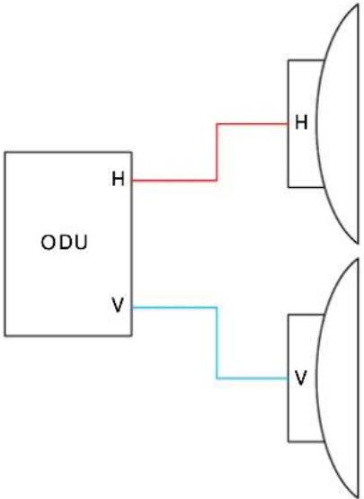 |
Protected links
Select one of the following PTP 700 end configurations for protected (Hot Standby 1+1 and 2+0) links:
Table 56 Supported end configurations, protected links
| Configuration | Schematic | |
| D | Integrated |  |
| E | Connectorized, one dual-polarized antenna, using the RF Combiner Kit |  |
| F | Connectorized, two dual-polarized antennas |  |
G Connectorized, two dual-polarized antennas, spatial diversity

flowchart
graph TD
    A["Primary ODU"] -->|H| B["H"]
    A -->|V| C["V"]
    D["Secondary ODU"] -->|V| E["V"]
    D -->|H| F["H"]
    B --> G["V"]
    C --> H["V"]
    F --> I["H"]

Note Configuration E incurs the additional RF losses of the RF Combiners and connecting cables. These losses can sensibly be offset by increasing the gain (and size) of the shared antenna.
End configurations for spatial diversity
There is no need to use the same configuration at both ends of a link with spatial diversity. It is sufficient (and sometimes preferable) to provide separate antennas at one end only. This approach differs from conventional licensed microwave links where separate antennas are needed at both ends. See Figure 56 below for an example where a shared antenna is used at the left of the figure and separate antennas are used at the right of the figure.
Figure 56 Protected spatial diversity link with separate antennas at one end

flowchart
graph TD
    subgraph Left_Circuit
        A["Primary ODU"] -->|H| B["P"]
        A -->|V| C["S"]
        D["Secondary ODU"] -->|H| E["P"]
        D -->|V| F["S"]
        B --> G["A"]
        E --> H["A"]
        G --> I["H"]
        H --> J["H"]
        I --> K["V"]
        J --> L["V"]
    end
    subgraph Right_Circuit
        M["Primary ODU"] -->|H| N["H"]
        M -->|V| O["V"]
        P["Secondary ODU"] -->|V| Q["H"]
        P --> R["V"]
        N --> S["H"]
        O --> T["V"]
        Q --> U["H"]
        R --> V["H"]
        S --> W["V"]
        T --> X["V"]
        U --> Y["H"]
        V --> Z["H"]
Further reading
| For information about... | Refer to... |
| Hot Standby operation | Hot Standby (1+1) link protection on page 1-9 |
| 2+0 operation | 2+0 link protection on page 1-11 |
| Spatial diversity | Spatial diversity on page 1-15 |
Configuration options for TDD synchronization
This section describes the different configuration options that may be used for implementing TDD synchronization in the PTP 700 Series. Schematic diagrams are included.
Using PTP-SYNC with PTP 45700

Note The PTP-SYNC unit is not supported for TDD synchronization with PTP 78700 ODUs. For these ODUs, use an alternative synchronization source.
The PTP 700 supports the following TDD synchronization configurations using PTP-SYNC:
- Single PTP link or HCMP sector configuration with PTP-SYNC on page 3-36.
- Cluster with PTP-SYNC and GPS receiver on page 3-37.
- Cluster with PTP-SYNC and no GPS receiver on page 3-38.

Attention The PTP-SYNC is compatible only with the AC+DC Power Injector 56V. PTP-SYNC is not compatible with standards-based power-over-Ethernet (PoE).
Single PTP link or HCMP sector configuration with PTP-SYNC
Each PTP link or HCMP sector requires one PTP-SYNC unit connected to the Master ODU and one compatible GPS receiver. Use this configuration where a site contains only one TDD master ODU. The GPS receiver and LPU can be replaced by an alternative compatible 1 Hz timing reference (Figure 57).
The wireless configuration settings are:
• Master Slave Mode = Master.
• TDD Synchronization Mode = Enabled.
• TDD Sync Device = PTPSYNC.
- Cluster Master Slave = Cluster Master.
- PTP Sync Site Reference = GPS/1PPS External.
Figure 57 TDD synchronization configuration - single link or sector with PTP-SYNC

flowchart
graph TD
    A["GPS receiver"] --> B["PTP-SYNC"]
    B --> C["PIDU IN"]
    B --> D["ODU OUT"]
    E["ODU"] --> B
    F["AC supply"] --> G["AC In"]
    G --> H["AC+DC Power Injector LAN"]
    H --> I["Customer LAN"]
    J["GPS/SYNC IN"] --> B
    K["SYNC OUT"] --> B
— Outdoor CAT5e cable, gel-filled, shielded with copper-plated steel.
CAT5e cable, foil or braid screened, with screened connectors.
CAT5e cable, unscreened or screened.
Ground cable.
Cluster with PTP-SYNC and GPS receiver
Each PTP link or HCMP sector requires one PTP-SYNC unit. Each site requires one compatible GPS receiver. Collocated PTP-SYNC units are connected together in a daisy-chain. Between two and ten PTP-SYNCs may be chained in this way. Use this configuration where a site contains collocated TDD Master ODUs in an extended network and where multiple sites have TDD master ODUs (Figure 58).
The wireless configuration settings are:
• Master Slave Mode = Master (all ODUs in cluster).
• TDD Synchronization Mode = Enabled.
• TDD Sync Device = PTPSYNC (all ODUs in cluster).
- Cluster Master Slave = Cluster Master (first ODU) and Cluster Slave (others).
- PTP Sync Site Reference = GPS/1PPS External (all ODUs in cluster).
Figure 58 TDD synchronization configuration - cluster with PTP-SYNC and GPS

flowchart
graph TD
    A["GPS receiver"] --> B["PTP-SYNC"]
    B --> C["Cluster Master ODU"]
    B --> D["PTP-SYNC"]
    D --> E["Cluster Slave ODU"]
    B --> F["PGS/SYNC IN SYNC OUT PIDU IN ODU OUT"]
    D --> G["PGS/SYNC IN SYNC OUT PIDU IN ODU OUT"]
    F --> H["AC supply AC In AC+DC Power Injector LAN"]
    G --> I["AC supply AC in AC+DC Power Injector LAN"]
    H --> J["Customer LAN"]
    I --> K["Customer LAN"]
    L["Cluster Master ODU"] --> B
    M["Cluster Slave ODU"] --> D
    N["PGS/SYNC IN SYNC OUT PIDU IN ODU OUT"] --> D
    O["PGS/SYNC IN SYNC OUT PIDU IN ODU OUT"] --> D
    P["PGS/SYNC IN SYNC OUT PIDU IN ODU OUT"] --> D
    Q["PGS/SYNC IN SYNC OUT PIDU IN ODU OUT"] --> D
    R["PGS/SYNC IN SYNC OUT PIDU IN ODU OUT"] --> D
    S["PGS/SYNC IN SYNC OUT PIDU IN ODU OUT"] --> D
    T["PGS/SYNC IN SYNC OUT PIDU IN ODU OUT"] --> D
    U["PGS/SYNC IN SYNC OUT PIDU IN ODU OUT"] --> D
    V["PGS/SYNC IN SYNC OUT PIDU IN ODU OUT"] --> D
    W["PGS/SYNC IN SYNC OUT PIDU IN ODU OUT"] --> D
    X["PGS/SYNC IN SYNC OUT PIDU IN ODU OUT"] --> D
    Y["PGS/SYNC IN SYNC OUT PIDU IN ODU OUT"] --> D
    Z["PGS/SYNC IN SYNC OUT PIDU IN ODU OUT"] --> D
    AA["PGS/SYNC IN SYNC OUT PIDU IN ODU OUT"] --> D
    AB["PGS/SYNC IN SYNC OUT PIDU IN ODU OUT"] --> D
    AC["PGS/SYNC IN SYNC OUT PIDU IN ODU OUT"] --> D
    AD["PGS/SYNC IN SYNC OUT PIDU IN ODU OUT"] --> D
    AE["PGS/SYNC IN SYNC OUT PIDU IN ODU OUT"] --> D
    AF["PGS/SYNC IN SYNC OUT PIDU IN ODU OUT"] --> D
    AG["PGS/SYNC IN SYNC OUT PIDU IN ODU OUT"] --> D
    AH["PGS/SYNC IN SYNC OUT PIDU IN ODU OUT"] --> D
    AI["PGS/SYNC IN SYNC OUT PIDU IN ODU OUT"] --> D
    AJ["PGS/SYNC IN SYNC OUT PIDU IN ODU OUT"] --> D
    AK["PGS/SYNC IN SYNC OUT PIDU IN ODU OUT"] --> D
    AL["PGS/SYNC IN SYNC OUT PIDU IN ODU OUT"] --> D
    AM["PGS/SYNC IN SYNC OUT PIDU IN ODU OUT"] --> D
    AN["PGS/SYNC IN SYNC OUT PIDU IN ODU OUT"] --> D
    AO["PGS/SYNC IN SYNC OUT PIDU IN ODU OUT"] --> D
    AP["PGS/SYNC IN SYNC OUT PIDU IN ODU OUT"] --> D
    AQ["PGS/SYNC IN SYNC OUT PIDU IN ODU OUT"] --> D
    AR["PGS/SYNC IN SYNC OUT PIDU IN ODU OUT"] --> D
    AS["PGS/SYNC IN SYNC OUT PIDU IN ODU OUT"] --> D
    AT["PGS/SYNC IN SYNC OUT PIDU IN ODU OUT"] --> D
    AU["PGS/SYNC IN SYNC OUT PIDU IN ODU OUT"] --> D
    AV["PGS/SYNC IN SYNC OUT PIDU IN ODU OUT"] --> D
    AW["PGS/SYNC IN SYNC OUT PIDU IN ODU OUT"] --> D
    AX["PGS/SYNC IN SYNC OUT PIDU IN ODU OUT"] --> D
    AY["Cluster Master ODU"] --> B
    AZ["Cluster Slave ODU"] --> B
— Outdoor CAT5e cable, gel-filled, shielded with copper-plated steel.
CAT5e cable, foil or braid screened, with screened connectors.
CAT5e cable, unscreened or screened.
Ground cable.
Cluster with PTP-SYNC and no GPS receiver
Each PTP link or HCMP sector requires one PTP-SYNC unit. PTP-SYNC units are connected together in a daisy-chain. Between two and ten PTP-SYNCs may be chained in this way. One ODU is designated as a cluster master. Use this configuration where all Master ODUs are colocated at a single site. As this configuration does not require a GPS receiver, it provides additional flexibility, particularly in applications requiring rapid deployment (Figure 59).
The wireless configuration settings are:
• Master Slave Mode = Master (all ODUs in cluster).
• TDD Synchronization Mode = Enabled.
• TDD Sync Device = PTPSYNC (all ODUs in cluster).
- Cluster Master Slave = Cluster Master (first ODU) and Cluster Slave (others).
- PTP Sync Site Reference = Internal (all ODUs in cluster).
Figure 59 TDD synchronization configuration - cluster with PTP-SYNC and no GPS
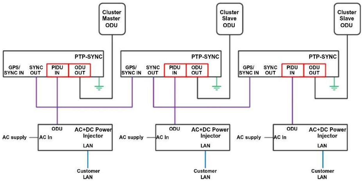
flowchart
graph TD
    subgraph Cluster Master ODU
        A["GPS/SYNC IN"] --> B["PTP-SYNC"]
        C["SYNC OUT"] --> B
        D["PIDU IN"] --> B
        E["ODU OUT"] --> B
    end

    subgraph Cluster Slave ODU
        F["GPS/SYNC IN"] --> G["PTP-SYNC"]
        H["SYNC OUT"] --> G
        I["PIDU IN"] --> G
        J["ODU OUT"] --> G
    end

    B --> K["AC Supply"]
    G --> L["AC Supply"]
    G --> M["AC Supply"]
    G --> N["AC Supply"]
    G --> O["AC Supply"]
    K --> P["AC Supply"]
    L --> Q["AC Supply"]
    M --> R["AC Supply"]
    N --> S["AC Supply"]
    O --> T["AC Supply"]
    P --> U["Customer LAN"]
    Q --> V["Customer LAN"]
    R --> W["Customer LAN"]
    S --> X["Customer LAN"]
— Outdoor CAT5e cable, gel-filled, shielded with copper-plated steel.
CAT5e cable, foil or braid screened, with screened connectors.
CAT5e cable, unscreened or screened.
Ground cable.
Using a direct connection between ODUs
Two PTP 700 Master ODUs may be synchronized in a standalone configuration using a direct cable connection between wired Ethernet ports. There is no option in this case to synchronize with a GPS receiver, and so no possibility of network-wide synchronization. This option may be useful in an isolated Hot Standby (1+1) link, an isolated 2+0 link, or at the centre point of a relay of two links using the same mast.
Aux Port to Aux Port
Configure one ODU to provide a free-running reference with the following settings:
• Master Slave Mode = Master (all ODUs in cluster).
• TDD Synchronization Mode = Enabled.
- TDD Sync Device = Cambium Sync Injector.
- Cambium Sync Input Port = Internal.
- Cambium Sync Output Port = Aux.
• TDD Holdover Mode = Best Effort.
• TDD Holdover Duration = 0 minutes.
Configure a second ODU to synchronize with the first ODU with the following settings:
• Master Slave Mode = Master (all ODUs in cluster).
- TDD Synchronization Mode = Enabled.
- TDD Sync Device = Cambium Sync Injector.
- Cambium Sync Input Port = Aux.
- Cambium Sync Output Port = None.
• TDD Holdover Mode = Best Effort.
• TDD Holdover Duration = 0 minutes.
TDD burst durations in PTP topology
Table 57 and Table 59 list the available TDD burst durations in TDD synchronization and PTP topology, with and without Long Frame Duration. Long Frame Duration is automatically enabled in Hot Standby (1+1) links.
Table 58 to Table 63 list the supported combinations of TDD burst durations in TDD synchronization and PTP topology, with and without Long Frame Duration. Long Frame Duration is automatically enabled in Hot Standby (1+1) links. These combinations provide all of the possible symmetrical burst durations and all of the asymmetrical burst durations where the smaller burst is the minimum allowed.
Table 57 Supported TDD burst durations in TDD synchronization, Long Frame Duration = Disabled
| Channel Bandwidth | Supported burst durations |
| 5 MHz | 1088 μs |
| 10 MHz | 1088 μs, 2176 μs |
| 15 MHz | 726 μs, 1453 μs, 2176 μs |
| 20 MHz | 544 μs, 1088 μs, 1632 μs, 2176 μs |
| 30 MHz | 726 μs, 1088 μs, 1453 μs, 2176 μs |
| 40 MHz | 544 μs, 816 μs, 1088 μs, 1632 μs, 2176 μs |
| 45 MHz | 484 μs, 726 μs, 970 μs, 1453 μs, 1937 μs |
Table 58 Supported combinations of TDD burst durations, Long Frame Duration = Disabled
| Channel Bandwidth | Master-Slave Burst Duration | Slave-Master Burst Duration |
| 5 MHz | 1088 μs | 1088 μs |
| 10 MHz | 1088 μs | 1088 μs |
| 2176 μs | 2176 μs | |
| 1088 μs | 2176 μs | |
| 2176 μs | 1088 μs | |
| 15 MHz | 726 μs | 726 μs |
| 1453 μs | 1453 μs | |
| 2176 μs | 2176 μs | |
| 726 μs | 1453 μs, 2176 μs | |
| 2176 μs, 1453 μs, | 726 μs | |
| 20 MHz | 544 μs | 544 μs |
| 1088 μs | 1088 μs | |
| 1632 μs | 1632 μs | |
| 2176 μs | 2176 μs | |
| 544 μs | 1088 μs, 1632 μs, 2176 μs | |
| 1088 μs, 1632 μs, 2176 μs | 544 μs | |
| 30 MHz | 726 μs | 726 μs |
| 1088 μs | 1088 μs | |
| 1453 μs | 1453 μs | |
| 2176 μs | 2176 μs | |
| 726 μs | 1088 μs, 1453 μs, 2176 μs | |
| 1088 μs, 1453 μs, 2176 μs | 726 μs | |
| 40 MHz | 544 μs | 544 μs |
| 816 μs | 816 μs | |
| 1088 μs | 1088 μs | |
| 1632 μs | 1632 μs | |
| 2176 μs | 2176 μs | |
| 544 μs | 816 μs, 1088 μs, 1632 μs, 2176 μs | |
| 816 μs, 1088 μs, 1632 μs, 2176 μs | 544 μs | |
| 45 MHz | 484 μs | 484 μs |
| 726 μs | 726 μs | |
| 970 μs | 970 μs | |
| 1453 μs | 1453 μs | |
| 1937 μs | 1937 μs | |
| 484 μs | 726 μs, 970 μs, 1453 μs, 1937 μs | |
| 726 μs, 970 μs, 1453 μs, 1937 μs | 484 μs |
Table 59 Supported TDD burst durations in TDD synchronization, Long Frame Duration = Enabled
| Channel Bandwidth | Supported burst durations |
| 20 MHz | 1088 μs, 1632 μs, 2176 μs, 2720 μs, 3264 μs, 3808 μs, 4352 μs, 4896 μs, 5440 μs, 5984 μs, 6528 μs |
| 30 MHz | 726 μs, 1088 μs, 1451 μs, 1814 μs, 2176 μs, 2539 μs, 2902 μs, 3264 μs, 3627 μs, 3990 μs, 4352 μs, 4715 μs, 5078 μs, 5440 μs |
| 40 MHz | 532 μs, 798 μs, 1064 μs, 1330 μs, 1596 μs, 1862 μs, 2128 μs, 2394 μs, 2660 μs, 2926 μs, 3192 μs, 3458 μs, 3724 μs, 3990 μs |
| 45 MHz | 486 μs, 728 μs, 971 μs, 1214 μs, 1456 μs, 1699 μs, 1942 μs, 2184 μs, 2427 μs, 2670 μs, 2912 μs, 3155 μs, 3398 μs, 3640 μs |
Table 60 Supported combinations of TDD burst durations, 20 MHz, Long Frame Duration = Enabled
| Master-Slave Burst Duration | Slave-Master Burst Duration |
| 1088 μs | 1088 μs |
| 1632 μs | 1632 μs |
| 2176 μs | 2176 μs |
| 2720 μs | 2720 μs |
| 3264 μs | 3264 μs |
| 3808 μs | 3808 μs |
| 4352 μs | 4352 μs |
| 4896 μs | 4896 μs |
| 5440 μs | 5440 μs |
| 5984 μs | 5984 μs |
| 6528 μs | 6528 μs |
| 1088 μs | 1632 μs, 2176 μs, 2720 μs, 3264 μs, 3808 μs, 4352 μs, 4896 μs, 5440 μs, 5984 μs, 6528 μs |
| 1632 μs, 2176 μs, 2720 μs, 3264 μs, 3808 μs, 4352 μs, 4896 μs, 5440 μs, 5984 μs, 6528 μs | 1088 μs |
Table 61 Supported combinations of TDD burst durations, 30 MHz, Long Frame Duration = Enabled
| Master-Slave Burst Duration | Slave-Master Burst Duration |
| 726 μs | 726 μs |
| 1088 μs | 1088 μs |
| 1451 μs | 1451 μs |
| 1814 μs | 1814 μs |
| 2176 μs | 2176 μs |
| 2539 μs | 2539 μs |
| 2902 μs | 2902 μs |
| 3264 μs | 3264 μs |
| 3627 μs | 3627 μs |
| 3990 μs | 3990 μs |
| 4352 μs | 4352 μs |
| 4715 μs | 4715 μs |
| 5078 μs | 5078 μs |
| 5440 μs | 5440 μs |
| 726 μs | 1088 μs, 1451 μs, 1814 μs, 2176 μs, 2539 μs, 2902 μs, 3264 μs, 3627 μs, 3990 μs, 4352 μs, 4715 μs, 5078 μs, 5440 μs |
| 1088 μs, 1451 μs, 1814 μs, 2176 μs, 2539 μs, 2902 μs, 3264 μs, 3627 μs, 3990 μs, 4352 μs, 4715 μs, 5078 μs, 5400 μs | 726 μs |
Table 62 Supported combinations of TDD burst durations, 40 MHz, Long Frame Duration = Enabled
| Master-Slave Burst Duration | Slave-Master Burst Duration |
| 532 μs | 532 μs |
| 798 μs | 798 μs |
| 1064 μs | 1064 μs |
| 1330 μs | 1330 μs |
| 1596 μs | 1596 μs |
| 1862 μs | 1862 μs |
| 2128 μs | 2128 μs |
| 2394 μs | 2394 μs |
| 2660 μs | 2660 μs |
| 2926 μs | 2926 μs |
| 3192 μs | 3192 μs |
| 3458 μs | 3458 μs |
| 3724 μs | 3724 μs |
| 3990 μs | 3990 μs |
| 532 μs | 798 μs, 1064 μs, 1330 μs, 1596 μs, 1862 μs, 2128 μs, 2394 μs, 2660 μs, 2926 μs, 3192 μs, 3458 μs, 3724 μs, 3990 μs |
| 798 μs, 1064 μs, 1330 μs, 1596 μs, 1862 μs, 2128 μs, 2394 μs, 2660 μs, 2926 μs, 3192 μs, 3458 μs, 3724 μs, 399O μs | 532 μs |
Table 63 Supported combinations of TDD burst durations, 45 MHz, Long Frame Duration = Enabled
| Master-Slave Burst Duration | Slave-Master Burst Duration |
| 486 μs | 486 μs |
| 728 μs | 728 μs |
| 971 μs | 971 μs |
| 1214 μs | 1214 μs |
| 1456 μs | 1456 μs |
| 1699 μs | 1699 μs |
| 1942 μs | 1942 μs |
| 2184 μs | 2184 μs |
| 2427 μs | 2427 μs |
| 2670 μs | 2670 μs |
| 2912 μs | 2912 μs |
| 3155 μs | 3155 μs |
| 3398 μs | 3398 μs |
| 3640 μs | 3640 μs |
| 486 μs | 728 μs, 971 μs, 1214 μs, 1456 μs, 1699 μs, 1942 μs, 2184 μs, 2427 μs, 2670 μs, 2912 μs, 3155 μs, 3398 μs, 3640 μs |
| 728 μs, 971 μs, 1214 μs, 1456 μs, 1699 μs, 1942 μs, 2184 μs, 2427 μs, 2670 μs, 2912 μs, 3155 μs, 3398 μs, 3640μs | 486 μs |
TDD frame durations
Table 64 and Table 65 list the available TDD frame durations in TDD synchronization and PTP topology, with and without Long Frame Duration.
Table 64 Supported TDD frame durations in TDD synchronization
| Channel bandwidth | Supported frame durations |
| 5 MHz to 30 MHz | 1140 μs, 1196 μs, 1250 μs, 1299 μs, 1309 μs, 1370 μs, 1439 μs, 1504 μs, 1575 μs, 1623 μs, 1650 μs, 1730 μs, 1805 μs, 1859 μs, 1908 μs, 2000 μs, 2079 μs, 2179 μs, 2283 μs, 2392 μs, 2500 μs, 2618 μs, 2747 μs, 2882 μs, 3012 μs, 3145 μs, 3311 μs, 3460 μs, 3610 μs, 3817 μs, 4000 μs, 4184 μs, 4367 μs, 4566 μs, 4785 μs, 5000 μs, 5236 μs, 5495 μs, 5714 μs, 6024 μs, 6410 μs |
| 40 MHz | 1299 μs, 1370 μs, 1623 μs, 2000 μs, 2283 μs, 2747 μs, 4000 μs, 4184 μs, 4566 μs, 5495 μs, 6024 μs |
| 45 MHz | 1250 μs, 1370 μs, 1575 μs, 1859 μs, 1908 μs, 2000 μs, 2079 μs, 2500 μs, 2618 μs, 3311 μs, 3460 μs, 3817 μs, 4000 μs, 4367 μs, 4566 μs, 5000 μs, 5236 μs |
Table 65 Additional supported TDD frame durations in TDD synchronization, Long Frame Duration
| Channel bandwidth | Supported frame durations |
| 20 MHz | 6849 μs, 7143 μs, 8065 μs, 8547 μs, 9259 μs, 9524 μs, 10000 μs, 10526 μs, 10989 μs, 11628 μs, 12195 μs, 13514 μs, 14286 μs |
| 30 MHz | 6849 μs, 7143 μs, 8065 μs, 8547 μs, 9259 μs, 9524 μs, 10000 μs, 10526 μs, 10989 μs, 11628 μs, 12195 μs, 135I4 μs |
| 40 MHz | 6849 μs, 7143 μs, 8065 μs, 8547 μs, 9259 μs, 9524 μs, 10000 μs |
| 45 MHz | 7143 μs, 8547 μs, 9259 μs |
TDD frame design for standalone synchronization
Two PTP 700 Master ODUs may be synchronized in a standalone configuration using a direct cable connection between wired Ethernet ports. There is no option in this case to synchronize with a GPS receiver, and so no possibility of network-wide synchronization. This option may be useful in an isolated Hot Standby (1+1) link or an isolated 2+0 link.
Select the TDD Frame parameters for standalone synchronized operation as follows:
1 Select the symmetric or asymmetric TDD burst duration for Master-Slave and Slave-Master directions from the options in TDD burst durations in PTP topology on page 3-40.
2 Determine the TDD frame duration for the link using LINKPlanner, selecting the standalone synchronization option. This will identify the shortest frame duration that accommodates the round trip delay for this link without considering other links in the same network. The recommended frame duration optimizes the capacity and efficiency of the link.
3 Set Slave Receive To Transmit Gap to the minimum value of:
• PTP 45700 2+0: 39 μs
• PTP 45700 Hot Standby (1+1): 46 μs
• PTP 78700 2+0: 99 μs
• PTP 78700 Hot Standby (1+1): 106 μs
4 Set TDD Frame Offset to 0. The link is not synchronized with a network-wide reference, so the offset is unimportant.
TDD frame design for network-wide synchronization
A network with multiple links may be synchronized with each Master ODU locked to the same network-wide reference. This requires the use of PTP-SYNC, with the associated GPS receiver.
Select the TDD Frame parameters for network-wide synchronized operation as follows:
1 Select the symmetric or asymmetric TDD burst duration for the network as Phase 1 and Phase 2 in the TDD frame. The options are listed in TDD burst durations in PTP topology on page 3-40.
2 In LINKPlanner, create a plan including all of the links in the network, selecting one of the network-wide synchronization options for each link.
3 In LINKPlanner, assign Phase 1 to either the Master-Slave or Slave-Master direction for each link.
4 Determine the common TDD frame duration for the network using the TDD Sync panel in LINKPlanner. LINKPlanner will identify the shortest frame duration that accommodates the round trip delay for the longest link and the furthest same-phase interference within the network. The recommended frame duration optimizes the overall capacity and efficiency of the network.
5 Determine the Slave Receive To Transmit Gap and TDD Frame Offset for each link in the network from the TDD Sync panel in LINKPlanner.
6 Configure PTP 700 links using the parameters provided by LINKPlanner.
Data network planning
This section describes factors to be considered when planning PTP 700 data networks.
Ethernet bridging
Table 66 summarizes Ethernet bridging specifications for PTP 700.
Table 66 PTP 700 Ethernet bridging specifications
| Ethernet Bridging | Specification |
| Protocol | IEEE802.1; IEEE802.1p; IEEE802.3 compatible |
| QoS | PTP topology: Eight wireless interface priority queues based on these standards: IEEE 802.1p, IEEE 802.1Q, IEEE 802.1ah, IEEE 802.1ad, DSCP IPv4, DSCP IPv6, MPLS TC, DSCP in PPP Session Stage |
| HCMP topology: Four wireless interface priority queues based on these standards: IEEE 802.1p, IEEE 802.1Q, IEEE 802.1ah, IEEE 802.1ad, DSCP IPv4, DSCP IPv6, MPLS TC, DSCP in PPP Session Stage | |
| Interfaces | 100BASE-TX, 1000BASE-T, 1000BASE-SX, 1000BASE-LX MDI/MDIX auto crossover supported |
| Max Ethernet frame size | 9600 bytes |
| Service classes for traffic | PTP topology: Eight classes |
| HCMP topology: Four classes |
Practical Ethernet rates depend on network configuration and higher layer protocols. Over the air throughput is capped to the rate of the Ethernet interface at the receiving end of the link.
Layer two control protocols
PTP 700 identifies layer two control protocols (L2CPs) from the Ethernet destination address of bridged frames. The QoS classification can be separately configured for these protocols.
Table 67 Destination address in layer two control protocols
| Destination address | Protocol |
| 01-80-c2-00-00-00 to 01-80-c2-00-00-0f | IEEE 802.1 bridge protocols |
| 01-80-c2-00-00-20 to 01-80-c2-00-00-2f | IEEE 802.1 Multiple Registration Protocol (MRP) |
| 01-80-c2-00-00-30 to 01-80-c2-00-00-3f | IEEE 802.1ag, Connectivity Fault Management (CFM) |
| 01-19-a7-00-00-00 to 01-19-a7-00-00-ff | Ring Automatic Protection Switching (R-APS) |
| 00-e0-2b-00-00-04 | Ethernet Automatic Protection Switching (EAPS) |
Ethernet port allocation
Services
PTP 700 supports five distinct virtual circuits or services for Ethernet traffic, namely:
- Data Service
- Management Service, configured as:
• In-Band Management
• Out-of-Band Management - Local Management Service
- Protection Service
- TD-90 Service
The Data, Out-of-Band Management, Local Management, Protection and TD-90 Services are carried in isolated virtual circuits. Ethernet frames in one service never cross over to another service. In-Band Management shares the same virtual circuit as the Data Service.
Port allocation rules
Decide how the three ODU Ethernet ports will be allocated to the services described above, based on the following rules.
No port can be allocated to more than one service, except that the Data Service and Management Service can share ports, in which case the combined service is described as Data with In-Band Management.
- Map TD-90 Service to SFP Port to enable the TD-90 SNMP Proxy function. The TD-90 cannot be used at an HCMP Master.
• In a Hot Standby link, map Protection Service to Aux Port or SFP Port. - In a protected (Hot Standby 1+1 or 2+0) link, map the Data Service to exactly one of the remaining unused wired Ethernet ports. This will normally be the Main PSU port but need not be so.
- In an unprotected link, map the Data Service to at least one of the remaining unused wired Ethernet ports.
- Map the Management Service to In-Band, or to any combination of the remaining unused Ethernet ports. If the Management Service is mapped to In-Band, it shares all of the ports selected for the Data Service. The Management Service can be disabled by mapping to None.
- Map the Local Management Service to any combination of the remaining unused Ethernet ports. The Local Management Service can be disabled by mapping to None.
The LAN Configuration page ensures that the Management Agent can always be reached using either the Management Service or the Local Management Service.
Mapping of ports and services
The rules described above allow for the following 21 distinct combinations of services:
Table 68 Combinations of services for one ODU
| Service combination | Figure |
| TD-90 + Data + Local Management | Figure 60 |
| TD-90 + Data + Out-of-Band Management | Figure 61 |
| TD-90 + Data with In-Band | |
| TD-90 + Data with In-Band + Local Management | Figure 62 |
| TD-90 + Data with In-Band + Data with In-Band | |
| Protection + Data + Local Management | Figure 63 |
| Protection + Data + Out-of-Band Management | Figure 64 |
| Protection + Data with In-Band | |
| Protection + Data with In-Band + Local Management | |
| Data + Local Management | |
| Data + Local Management + Local Management | |
| Data + Out-of-Band Management | |
| Data + Out-of-Band Management + Out-of-Band Management | |
| Data + Out-of-Band Management + Local Management | Figure 65 |
| Data + Data + Out-of-Band Management | |
| Data + Data + Local Management | |
| Data with In-Band | |
| Data with In-Band + Local Management | Figure 66 |
| Data with In-Band + Local Management + Local Management | |
| Data with In-Band + Data with In-Band | |
| Data with In-Band + Data with In-Band + Local Management | |
| Data with In-Band + Data with In-Band + Data with In-Band |
Figure 60 to Figure 66 illustrate the internal routing of Ethernet traffic in selected examples of the service combinations listed in Table 68.
Figure 60 Ports and Services: TD-90 + Data + Local

flowchart
graph TD
    A["Management Agent"] --> B["MAC Relay"]
    B --> C["MAC Relay"]
    C --> D["Wireless Port"]
    E["Ethernet Port"] --> F["SFP Port"]
    F --> G["MAC Relay"]
    G --> C
    H["Local Management"] --> I["Ethernet Port"]
    I --> J["MAC Relay"]
    J --> C
    K["Customer Data"] --> L["Ethernet Port"]
    L --> M["MAC Relay"]
    M --> C
    N["PTP 700 ODU"] --> O["Local Management"]
    N --> P["TD90"]
    N --> Q["Customer Data"]
Figure 61 Ports and Services: TD-90 + Data + Out-of-Band

flowchart
graph TD
    A["Out-of-Band Management"] --> B["Ethernet Port"]
    C["TD90"] --> D["SFP Port"]
    E["Customer Data"] --> F["Ethernet Port"]
    B --> G["MAC Relay"]
    D --> H["MAC Relay"]
    F --> I["MAC Relay"]
    G --> J["Management Agent"]
    H --> J
    I --> K["Wireless Port"]
    J --> K
    style A fill:#f9f,stroke:#333
    style C fill:#f9f,stroke:#333
    style E fill:#f9f,stroke:#333
    style B fill:#ccf,stroke:#333
    style D fill:#ccf,stroke:#333
    style F fill:#ccf,stroke:#333
    style G fill:#cff,stroke:#333
    style H fill:#cff,stroke:#333
    style I fill:#cff,stroke:#333
    style J fill:#ffc,stroke:#333
    style K fill:#ffc,stroke:#333
Figure 62 Ports and Services: TD-90 + Data with In-Band + Local

flowchart
graph TD
    A["Management Agent"] -->|Red arrow| B["MAC Relay"]
    B --> C["MAC Relay"]
    C --> D["MAC Relay"]
    D --> E["Wireless Port"]
    F["Ethernet Port"] --> G["SFP Port"]
    H["Ethernet Port"] --> I["Local Management"]
    J["Customer Data and In-Band Management"] --> K["Local Management"]
    L["PTP 700 ODU"] --> M["Local Management"]
    style A fill:#f9f,stroke:#333
    style F fill:#ccf,stroke:#333
    style J fill:#ccf,stroke:#333
    style L fill:#ccf,stroke:#333
    style B fill:#ff9,stroke:#333
    style C fill:#ff9,stroke:#333
    style D fill:#ff9,stroke:#333
    style E fill:#ff9,stroke:#333
    style G fill:#ccf,stroke:#333
    style H fill:#ccf,stroke:#333
    style I fill:#ccf,stroke:#333
Figure 63 Ports and Services: Protection + Data + Local

flowchart
graph TD
    A["Management Agent"] --> B["MAC Relay"]
    B --> C["MAC Relay"]
    C --> D["MAC Relay"]
    D --> E["Wireless Port"]
    F["Ethernet Port"] --> B
    G["Ethernet Port"] --> C
    H["Ethernet Port"] --> D
    I["Protection"] --> F
    J["Local Management"] --> G
    K["Customer Data"] --> L["Ethernet Port"]
    M["PTP 700 ODU"] --> N["MAC Relay"]
    N --> D
    style A fill:#f9f,stroke:#333
    style B fill:#ccf,stroke:#333
    style C fill:#cfc,stroke:#333
    style D fill:#fcc,stroke:#333
    style E fill:#cff,stroke:#333
    style F fill:#ffc,stroke:#333
    style G fill:#ffc,stroke:#333
    style H fill:#ffc,stroke:#333
    style I fill:#ffc,stroke:#333
    style J fill:#ffc,stroke:#333
    style K fill:#ffc,stroke:#333
    style L fill:#ffc,stroke:#333
Figure 64 Ports and Services: Protection + Data + Out-of-Band
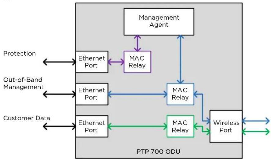
flowchart
graph TD
    A["Management Agent"] --> B["MAC Relay"]
    B --> C["MAC Relay"]
    C --> D["Wireless Port"]
    D --> E["MAC Relay"]
    E --> F["Ethernet Port"]
    F --> G["ETernet Port"]
    G --> H["ETernet Port"]
    H --> I["ETernet Port"]
    I --> J["ETernet Port"]
    J --> K["ETernet Port"]
    K --> L["ETernet Port"]
    L --> M["ETernet Port"]
    M --> N["ETernet Port"]
    N --> O["ETernet Port"]
    O --> P["ETernet Port"]
    P --> Q["ETernet Port"]
    Q --> R["ETernet Port"]
    R --> S["ETernet Port"]
    S --> T["ETernet Port"]
    T --> U["ETernet Port"]
    U --> V["ETernet Port"]
    V --> W["ETernet Port"]
    W --> X["ETernet Port"]
    X --> Y["ETernet Port"]
    Y --> Z["ETernet Port"]
    Z --> AA["ETernet Port"]
    AA --> AB["ETernet Port"]
    AB --> AC["ETernet Port"]
    AC --> AD["ETernet Port"]
    AD --> AE["ETernet Port"]
    AE --> AF["ETernet Port"]
    AF --> AG["ETernet Port"]
    AG --> AH["ETernet Port"]
    AH --> AI["ETernet Port"]
    AI --> AJ["ETernet Port"]
    AJ --> AK["ETernet Port"]
    AK --> AL["ETernet Port"]
    AL --> AM["ETernet Port"]
    AM --> AN["ETernet Port"]
    AN --> AO["ETernet Port"]
    AO --> AP["ETernet Port"]
    AP --> AQ["ETernet Port"]
    AQ --> AR["ETernet Port"]
    AR --> AS["ETernet Port"]
    AS --> AT["ETernet Port"]
    AT --> AU["ETernet Port"]
    AU --> AV["ETernet Port"]
    AV --> AW["ETernet Port"]
    AW --> AX["ETernet Port"]
    AX --> AY["ETernet Port"]
    AY --> AZ["ETernet Port"]
    AZ --> BA["ETernet Port"]
    BA --> BB["ETernet Port"]
    BB --> BC["ETernet Port"]
    BC --> BD["ETernet Port"]
    BD --> BE["ETernet Port"]
    BE --> BF["ETernet Port"]
    BF --> BG["ETernet Port"]
    BG --> BH["ETernet Port"]
    BH --> BI["ETernet Port"]
    BI --> BJ["ETernet Port"]
    BJ --> BK["ETernet Port"]
    BK --> BL["ETernet Port"]
    BL --> BM["ETernet Port"]
    BM --> BN["ETernet Port"]
    BN --> BO["ETernet Port"]
    BO --> BP["ETernet Port"]
    BP --> BQ["ETernet Port"]
    BQ --> BR["ETernet Port"]
    BR --> BS["ETernet Port"]
    BS --> BT["ETernet Port"]
    BT --> BU["ETernet Port"]
    BU --> BV["ETernet Port"]
    BV --> BW["ETernet Port"]
    BW --> BX["ETernet Port"]
    BX --> BY["ETernet Port"]
    BY --> BZ["ETernet Port"]
Figure 65 Ports and Services: Data + Out-of-Band + Local

flowchart
graph TD
    A["Management Agent"] --> B["MAC Relay"]
    B --> C["MAC Relay"]
    C --> D["Wireless Port"]
    E["Local Management"] --> F["Ethernet Port"]
    G["Out-of-Band Management"] --> H["Ethernet Port"]
    I["Customer Data"] --> J["Ethernet Port"]
    F <--> B
    H <--> C
    J <--> D
    B <--> C
    C <--> D
    style A fill:#f9f,stroke:#333
    style B fill:#ccf,stroke:#333
    style C fill:#cfc,stroke:#333
    style D fill:#fcc,stroke:#333
Figure 66 Ports and Services: Data with In-Band + Local
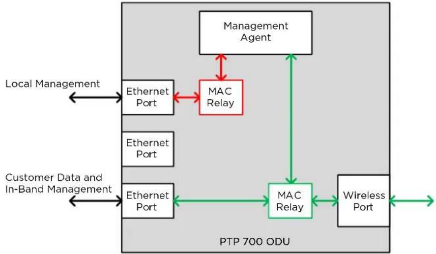
flowchart
graph TD
    A["Management Agent"] -->|Red arrow| B["MAC Relay"]
    B --> C["MAC Relay"]
    C --> D["Wireless Port"]
    D --> E["Local Management"]
    F["Ethernet Port"] --> B
    G["Ethernet Port"] --> C
    H["Ethernet Port"] --> C
    I["Customer Data and In-Band Management"] --> F
    I --> G
    I --> H
    style A fill:#f9f,stroke:#333
    style F fill:#ccf,stroke:#333
    style G fill:#ccf,stroke:#333
    style H fill:#ccf,stroke:#333
    style I fill:#ccf,stroke:#333
    subgraph PTP 700 ODU
        B --> C
        C --> D
        E --> D
        F --> E
        G --> E
        H --> E
    end
Use a compatible combination of services at both ends of the link
PTP 700 supports flexible allocation of ports to services, and this allocation may be different at the two ends of the link. However, the management service configuration must be compatible between the two ends of the link. Ensure that both ends of the link are configured for In-Band management, or both ends are configured for Out-of-Band Management, or the management services is disabled at both ends.

Warning Do not mix In-band and Out-of-Band management in the same link.
Additional port allocation rules
The three Ethernet ports are generally interchangeable, except for some specific additional rules listed below:
- If the system is to be used in a Synchronous Ethernet hierarchy, ensure that the upstream timing source is connected to the Main PSU or Fiber SFP ports (downstream devices can be connected to any port)
- If the system is operating as an IEEE 1588-2008 Transparent Clock, ensure the data path does not traverse the Copper SFP port.

Note The Main PSU port is always used to supply power to the ODU, even when it is not allocated to a data or management service.

Note The procedure for configuring these ports at the web interface is described in LAN Configuration page on page 6-60.

Note Transparent Clock is not supported over the SFP port with Copper connectivity.
VLAN membership
Decide if the IP interface of the ODU management agent will be connected in a VLAN. If so, decide if this is a standard (IEEE 802.1Q) VLAN or provider bridged (IEEE 802.1ad) VLAN, and select the VLAN ID for this VLAN.
Use of a separate management VLAN is strongly recommended. Use of the management VLAN helps to ensure that the ODU management agent cannot be accessed by customers.
If the system is to operate as an IEEE 1588-2008 Transparent Clock, decide if residence time corrections should be made to:
- All 1588 event frames, regardless of VLAN membership, or
- Only 1588 event frames in a specific customer bridged VLAN, or
- Only 1588 event frames in a specific provider bridged VLAN
Priority for management traffic
Choose the Ethernet and IP (DSCP) priority for management traffic generated within the ODU management agent. The priority should be selected so as to be consistent with existing policy on priority of management traffic in the network. Use of a high priority is strongly recommended to ensure that management traffic is not discarded if the link is overloaded.
Ensure that the priority assigned to management traffic is consistent with the quality of service scheme configured for bridged Ethernet traffic. If QoS for bridged traffic is based on the IP/MPLS scheme, set the DSCP management priority to map to a high priority queue. If QoS for bridged traffic is based on the Ethernet scheme, set the VLAN management priority to map to a high priority queue.
IP interface for NMS
Select the IP version for the IP interface of the ODU management agent. PTP 700 can operate in IPv4 mode, IPv6 mode, or in a dual IPv4/IPv6 mode. Choose one IPv4 address and/or one IPv6 address for the IP interface of the ODU management agent. The IP address or addresses must be unique and valid for the connected network segment and VLAN.
Find out the correct subnet mask (IPv4) or prefix length (IPv6) and gateway IP address for this network segment and VLAN.
Ensure that the design of the data network permits bidirectional routing of IP datagrams between network management systems and the ODUs. For example, ensure that the gateway IP address identifies a router or other gateway that provides access to the rest of the data network.
IP interface for integrated TD-90 management
The IPv4 interface in the TD-90 Service is configured automatically.
Quality of service for bridged Ethernet traffic
Decide how quality of service will be configured in PTP 700 to minimize frame loss and latency for high priority traffic. Wireless links often have lower data capacity than wired links or network equipment like switches and routers, and quality of service configuration is most critical at network bottlenecks.
In the PTP topology, PTP 700 provides eight queues for traffic waiting for transmission over the wireless link. Q0 is the lowest priority queue and Q7 is the highest priority queue. Traffic is scheduled using strict priority; in other words, traffic in a given queue is transmitted when all higher-priority queues are empty.
In the HCMP topology the general arrangement is similar but the ODU provides four queues for traffic awaiting transmission in each of the wireless links.
Layer 2 control protocols
Select the transmission queue for each of the recognised layer 2 control protocols (L2CP). These protocols are essential to correct operation of the Ethernet network, and are normally mapped to a high priority queue. Ethernet frames that match one of the recognized L2CPs are not subject to the Ethernet and IP/MPLS classification described below.
Priority schemes
Select the priority scheme based on Ethernet priority or IP/MPLS priority to match QoS policy in the rest of the data network. Ethernet priority is also known as Layer 2 or link layer priority. IP/MPLS priority is also known as Layer 3 or network layer priority.
Ethernet priority scheme
Ethernet priority is encoded in a VLAN tag. Use the Ethernet priority scheme if the network carries traffic in customer or service provider VLANs, and the priority in the VLAN tag has been set to indicate the priority of each type of traffic. Select a suitable mapping from the Ethernet priority to the eight PTP 700 queues.
An advantage of Ethernet priority is that any VLAN-tagged frame can be marked with a priority, regardless of the higher-layer protocols contained within the frame. A disadvantage of Ethernet priority is that the priority in the frame must be regenerated whenever traffic passes through a router.
IP/MPLS priority scheme
IP priority is determined by the DSCP value encoded in the ToS field in IPv4 and Traffic Class in IPv6. PTP 700 can locate the DSCP value in IP headers encapsulated within VLAN tags and/or PPP and PPPoE headers. The DSCP field provides 64 levels of priority. PTP 700 selects a suitable mapping from these DSCP values to the eight (PTP) or four (HCMP) PTP 700 queues.
The advantages of IP priority are that priority in the IP header is normally propagated transparently through a router, also the DSCP field supports a large number of distinct priority code points. A disadvantage of DSCP is that frames receive a single default classification if they contain a network layer protocol other than IPv4 or IPv6. This is controlled by the user setting the Unknown Network Layer Protocol queue value in the same QoS Configuration page under IP/MPLS QoS.
MPLS priority is encoded in the traffic class (TC) field in the outermost MPLS label. Select a suitable mapping from MPLS TC to the eight (PTP) or four (HCMP) PTP 700 queues.
Integrated management of TD-90
In the Integrated deployment scenario for the TD-90 antenna positioner, the IP interfaces for the PTP 700 and TD-90 are configured automatically, assuming an isolated Ethernet link.
Ensure that the connection between the PTP 700 and TD-90 is a dedicated point-to-point wired Ethernet cable. These interfaces should not be connected to a bridged management network.
"Daisy-chaining" PTP 700 links
When connecting two or more PTP 700 links together in a network (daisy-chaining), do not install direct copper Cat5e connections between the PSUs. Each PSU must be connected to the network terminating equipment using the LAN port. To daisy-chain PTP 700 links, install each ODU-to-ODU link using one of the following solutions:
- A copper Cat5e connection between the Aux ports of two ODUs. For details of the Ethernet standards supported and maximum permitted cable lengths, see Ethernet standards and cable lengths on page 2-27.
- A copper Cat5e connection between the Aux port of one ODU and the SFP port of the next ODU (using a copper SFP module). For details of the Ethernet standards supported and maximum permitted cable lengths, see Ethernet standards and cable lengths on page 2-27.
- Optical connections between the ODUs (SFP ports) using optical SFP modules at each ODU. For details of the Ethernet standards supported and maximum permitted cable lengths, see SFP module kits on page 2-33.
Green Ethernet switches
Do not connect PTP 700 units to Ethernet networking products that control the level of the transmitted Ethernet signal based on the measured length of the Ethernet link, for example Green Ethernet products manufactured by D-Link Corporation. The Ethernet interfaces in these networking products do not work correctly when connected directly to the PTP 700 PSU.
Network management planning
Planning for cnMaestro
When configured for management using cnMaestro, the PTP 700 ODU creates an outgoing HTTPS connection to the server from the IP interface of the management agent. To use the cnMaestro Cloud server, ensure that the management network allows outgoing connections to the public Internet. This normally involves the use of a security firewall to protect the management network from incoming connections. To use the On-Premises server, ensure that the server is reachable from the PTP 700 management network.
PTP 700 ODUs are authenticated to the cnMaestro server as part of the Onboarding process to prevent them from being claimed by other operators. To use the ODU's MAC Addresses for device authentication, ensure that the device is included in the list of PTP 700 device addresses on the server. To use Cambium ID for device authentication, ensure that the Cambium ID is known for the network, and ensure that a suitable Onboarding Key is configured on the server and issued to the installer.
To use a Fully Qualified Domain Name (FQDN) for the server address, ensure that the DNS feature is enabled and configured in the PTP 700. The FQDN (and thus DNS) is always used for the cnMaestro Cloud server.
The ODU contains the following third-party trusted root CA certificates:
- Amazon Root CA 1
- Amazon Root CA 2
- Comodo
- Digicert
- GeoTrust
- GoDaddy
- Let's Encrypt
- Verisign
Standard templates in the simplified web interface
PTP 700 provides four standard configuration templates. Standard configuration templates are applied by an operator with the Installer user-role using the simplified Installation Wizard in the web-based management interface. The standard configuration templates are pre-configured and optimized to address likely deployment use-cases.
Table 69 lists the predefined configuration that is applied in each of the four standard installation templates in the simplified web interface. Attributes shown as "Input" will be configured by the Installer user in the simplified Installation Wizard. The remaining configuration will be reset to default values.

Note Security parameters are not modified by applying a standard template.
Table 69 PTP 700 Standard Templates
| Category | Attribute | Most Robust | Best Range | Best Performance | HCMP |
| Wireless | Topology | PTP | PTP | PTP | HCMP |
| Master Slave Mode | Configure | Configure | Configure | Configure | |
| Protection Mode | Disabled | Disabled | Disabled | Disabled | |
| Link Name | Configure | Configure | Configure | - | |
| Site Name | Configure | Configure | Configure | Configure | |
| Network | IP Version | IPv4 | IPv4 | IPv4 | IPv4 |
| IPv4 address | Configure | Configure | Configure | Configure | |
| Subnet Mask | Configure | Configure | Configure | Configure | |
| Gateway IP Address | Configure | Configure | Configure | Configure | |
| DNS Resolver | Disabled | Disabled | Disabled | Disabled | |
| Mapping services | TD90 Service | None | None | None | None |
| Data Service | Main PSU Port | Main PSU Port | Main PSU Port | Main PSU Port | |
| Management Service | In-Band | In-Band | In-Band | In-Band | |
| Local Management Service | None | None | None | None | |
| Management Configuration | cnMaestro | Disabled | Disabled | Disabled | Disabled |
| Wireless | Access Method | Group Access | Group Access | Group Access | Group Access |
| Group ID | Configure | Configure | Configure | Configure | |
| Max number of Slaves | -- | - | - | 8 | |
| TDD Frame Configuration Mode | - | - | - | Standard Mode | |
| HCMP Link Symmetry | - | - | - | 1 to 1 | |
| HCMP Maximum Link Range | - | - | - | 30 km | |
| ATPC HCMP Master Tx Power | - | - | - | 29 dBm | |
| Dual Payload | Disabled | Enabled | Enabled | Enabled | |
| Max Modulation Mode | 16QAM 0.63 | 256QAM 0.81 | 256QAM 0.81 | 256QAM 0.81 | |
| Min Modulation Mode | BPSK | BPSK | BPSK | BPSK | |
| Link Optimization | IP Traffic | IP Traffic | IP Traffic | IP Traffic | |
| TDD Synchronization Mode | Disabled | Disabled | Disabled | Disabled | |
| Long Frame Duration | Disabled | Disabled | Disabled | Disabled | |
| Regulatory Band | 95 | 95 | 95 | 95 | |
| Channel Raster | 5 MHz | 5 MHz | 5 MHz | 10 MHz | |
| Channel Bandwidth | 10 MHz | 30 MHz | 40 MHz | 40 MHz | |
| Link Symmetry | Adaptive | Adaptive | Adaptive | Adaptive | |
| Spectrum Management Control | DSO | DSO | DSO | DSO | |
| Extended Spectrum Scanning | Disabled | Disabled | Disabled | Disabled | |
| Lower Centre Frequency | 4405.0 MHz | 4415.0 MHz | 4420.0 MHz | 4420.0 MHz | |
| Tx Color Code | A | A | A | A | |
| Rx Color Code | A | A | A | A | |
| Max Tx Power | Configure | Configure | Configure | Configure | |
| ATPC Peer Rx Max Power | -35 | -35 | -35 | -35 | |
| ATPC HCMP Master Target Rx Power | -52 | -52 | -52 | -52 | |
| Installation Mode | Configure | Configure | Configure | Configure | |
| Ranging Mode | 100 km | 100 km | 40 km | - | |
| Antenna Gain | 23 dBi | 23 dBi | 23 dBi | 23 dBi | |
| Cable loss | 0 dB | 0 dB | 0 dB | 0 dB | |
| Spectrum Expert | Asymmetric DSO | Enabled | Enabled | Enabled | Enabled |
| Management | SNMPv2 | Enabled | Enabled | Enabled | Enabled |
| Telnet | Disabled | Disabled | Disabled | Disabled | |
| Access Control | Disabled | Disabled | Disabled | Disabled | |
| SNMP Control of HTTP | Disabled | Disabled | Disabled | Disabled | |
| TFTP | Disabled | Disabled | Disabled | Disabled | |
| Debug Access | Disabled | Disabled | Disabled | Disabled | |
| XSFP | Enabled | Enabled | Enabled | Enabled | |
| RADIUS Client | Disabled | Disabled | Disabled | Disabled | |
| User accounts | Identity User Accounts | Enabled | Enabled | Enabled | Enabled |
| Web properties | Distance Units | Metric | Metric | Metric | Metric |
| SNMP | SNMP Version | v1/2c | v1/2c | v1/2c | v1/2c |
Custom templates in the simplified web interface
PTP 700 provides up to eight user-defined custom configuration templates. Custom configuration templates are applied by an operator with the Installer user-role using the Simplified Installation Wizard in the web-based management interface.
The custom configuration templates are created, imported, exported, and deleted by operators with the Security Officer or System Administrator user-roles using the Template Manager page in the web-based management interface.
Each configuration template captures the complete non-volatile configuration of the PTP 700 ODU, with the following exceptions:
- License Key
• Equipment configuration
- Unit Name
- Site Name
• Security configuration
- Antenna configuration
- Antenna Type
-
Antenna Selection
-
Web properties
- Selected editable controls
The editable controls are as follows:
- Master Slave Mode
• Target MAC Address - Link Name
- Group ID
• Maximum Transmit Power - Installation Mode
- IP Configuration
To create a new custom template, configure the ODU exactly as required for the particular application, select the editable controls that should be individually-configured by an Installer user in the simplified Installation Wizard, and create the template using a meaningful template name.
Custom templates can be exported from a PTP 700 ODU to a management PC, and then imported into other PTP 700 ODUs. By this means, it is possible to install the identical templates across an inventory of PTP 700 ODUs. Alternatively, it is possible to create different custom templates for each ODU.
Planning for SNMP operation
This section describes how to plan for PTP 700 links to be managed remotely using SNMP.
Supported MIBs
Ensure that the following MIBs are loaded on the network management system.
• RFC-1493. BRIDGE-MIB
• RFC-2233. IF-MIB
• RFC-3411. SNMP-FRAMEWORK-MIB
• RFC-3412. SNMP-MPD-MIB
• RFC-3413. SNMP-TARGET-MIB
• RFC-3414. SNMP-USER-BASED-SM-MIB
• RFC-3415. SNMP-VIEW-BASED-ACM-MIB
• RFC-3418. SNMPv2-MIB
• RFC-3826. SNMP-USM-AES-MIB
- RFC-4293 IP-MIB
• PTP 700 Series proprietary MIB

Note The proprietary MIBs are provided in the PTP 700 Series software download files in the support website (see Contacting Cambium Networks on page 1).
Supported notifications
The supported notifications are as follows:
- Cold start
- Wireless Link Up/Down
- Channel Change
• DFS Impulse Interference - Authentication Failure
- Main PSU Port Up Down
- Aux Port Up Down
- SFP Port Up Down
Supported diagnostic alarms
PTP 700 supports the diagnostic alarms listed in Table 229.
The web-based interface may be used to enable or disable generation of each supported SNMP notification or diagnostic alarm.
Enabling SNMP
Enable the SNMP interface for use by configuring the following attributes in the SNMP Configuration page:
• SNMP State (default disabled)
• SNMP Version (default SNMPv1/2c)
• SNMP Port Number (default 161)
SNMP Configuration Mode
Configuration attributes accessed using the SNMP Configuration Mode
The following configuration management attributes can be accessed via the SNMP interface using the SNMP Configuration Mode:
Table 70 Attributes accessed in SNMP Configuration Mode
| Category | Attributes |
| Quality of Service | ethernetPriorityQueueMappingiPDSCPPriorityQueueMappingl2CPPriorityQueueMappingmPLSTCPriorityQueueMappingoOBPriorityQueueMappingunknownNetworkPriorityQueueMapping |
| Wireless Topology | wirelessTopologyhotStandbyPreferencemasterSlaveModeprotectionMode |
| Interface Configuration | auxPortAllocationauxPortAutoMdixauxPortAutoNegAdvertisementauxPortAutoNegotiationauxPortForcedConfigurationauxPortPowerOverEthernetOutputauxPortSSMTxdataPortPauseFramesdataPortWirelessDownAlertdNSPrimaryServerdNSResolverdNSServerInternetAddressdNSServerPortNumberdSCPManagementPriorityethernetLoopbackModegatewayIPAddressIPv4AddressIPv6AddressIPv6GatewayAddressIPv6PrefixLengthiPVersionmainPSUPortAllocationmainPSUPortAutoMdixmainPSUPortAutoNegAdvertisementmainPSUPortAutoNegotiationmainPSUPortForcedConfigurationmainPSUPortQLRxOverwritemainPSUPortSSMTxmanagementNetworkAccessEnabledmanagementPortWirelessDownAlertsFPPortAllocationsFPPortAutoMdixsFPPortAutoNegAdvertisementsFPPortAutoNegotiationsFPPortForcedConfigurationsFPPortQLRxOverwritesFPPortSSMTxsubnetMasksyncEEquipmentClocksyncESlavePort |
| syncETracking | |
| transparentClock | |
| transparentClockPort | |
| transparentClockVID | |
| transparentClockVLAN | |
| useVLANForManagementInterfaces | |
| vLANManagementPriority | |
| vLANManagementVID | |
| Wireless Configuration | accessMethod |
| antennaGain | |
| antennaSelection | |
| cableLoss | |
| channelBandwidth | |
| connectorizedAntennaType | |
| distanceUnits | |
| dualPayload | |
| extendedSpectrumScanning | |
| fixedRxFrequencyKHz | |
| fixedTxFrequencyKHz | |
| groupID | |
| hCMPMaximumLinkRange | |
| installationMode | |
| linkModeOptimization | |
| linkName | |
| linkSymmetry | |
| longFrameDuration | |
| lowerCenterFrequencyKHz | |
| masterReceivePowerThreshold | |
| maximumReceiveModulationMode | |
| maximumTransmitPower | |
| minimumDataModulationMode | |
| rangingMode | |
| regulatoryBand | |
| slaveScan | |
| spectrumManagementControl | |
| spectrumManagementControlRadar | |
| targetMACAddress | |
| targetRange | |
| tDDSynchronizationMode | |
| transmitterChannels | |
| transmitterChannelsControl | |
| upperCenterFrequencyKHz | |
| userConfiguredMaxModulationMode | |
| TDD Synchronization | cambiumSyncConfigurePortcambiumSyncOutputPortclusterMasterSlavemaxBurstDurationpTPSyncSiteReferenceslaveReceiveToTransmitGaptDDFrameDurationtDDFrameOffsettDDHoldoverDurationtDDHoldoverModetDDSyncDevice |
| TDD Frame | downlinkSlotsLimitdownlinkSlotsRequestdownlinkTimeslotsdynamicAllocationhCMPLinkSymmetrymaximumNumberOfSlavestDDFrameConfigurationModeuplinkSlotsLimituplinkSlotsRequestuplinkTimeslots |
Transactional model
The SNMP Configuration Mode uses a transactional model to commit changes to multiple attributes in a single action, applying context-sensitive validation equivalent to validation in the web-based interface.
Attributes that are hidden in the web-based interface on the basis of the configuration of preceding attributes are silently ignored without validation if the same configuration is applied in the SNMP Configuration Mode. For example, a change to IPv6Address is applied if iPVersion is set to IPv6, but ignored if iPVersion is set to IPv4.
The steps in making configuration changes using the Configuration Mode are shown in Figure 67.
To abandon changes at any point without committing, SET SNMP Configuration Mode = Disabled.

Note Attributes accessed using SNMP Configuration Mode (Table 69) can only be changed using the configuration mode; any attempt to change these attributes using SNMP will be rejected if the configuration mode is disabled.
Read-write attributes that are not accessed using SNMP Configuration Mode can only be changed when SNMP Configuration Mode is disabled.

Note Attribute values that have been changed using SET messages while SNMP Configuration Mode is Enabled will not be apparent in a GET response for that attribute until after changes have been committed.
Figure 67 Flow chart for SNMP Configuration Mode
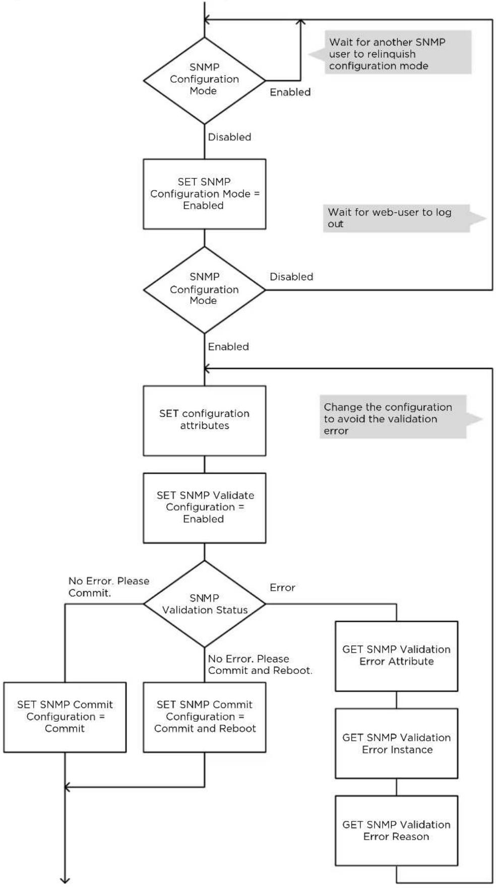
flowchart
graph TD
    A["SNMP Configuration Mode"] -->|Disabled| B["SET SNMP Configuration Mode = Enabled"]
    B --> C{SNMP Configuration Mode}
    C -->|Disabled| D["SET configuration attributes"]
    C -->|Enabled| E["SET SNMP Validation Configuration = Enabled"]
    D --> F["SET SNMP Validate Configuration = Enabled"]
    F --> G{SNMP Validation Status}
    G -->|No Error. Please Commit.| H["SET SNMP Commit Configuration = Commit"]
    G -->|Yes| I["SET SNMP Commit Configuration = Commit and Reboot"]
    I --> J["GET SNMP Validation Error Attribute"]
    J --> K["GET SNMP Validation Error Instance"]
    K --> L["GET SNMP Validation Error Reason"]
    L --> M["End"]
    C -->|Wait for another SNMP user to relinquish configuration mode| N["Start"]
    N --> A
    style A fill:#f9f,stroke:#333
    style B fill:#ccf,stroke:#333
    style C fill:#cfc,stroke:#333
    style D fill:#fcc,stroke:#333
    style E fill:#cff,stroke:#333
    style F fill:#ffc,stroke:#333
    style G fill:#cfc,stroke:#333
    style H fill:#fcc,stroke:#333
    style I fill:#cff,stroke:#333
    style J fill:#fcc,stroke:#333
    style K fill:#fcc,stroke:#333
    style L fill:#fcc,stroke:#333
    style M fill:#fcc,stroke:#333
Further reading
| For information about... | Refer to... |
| Planning for SNMPv3 security | Planning for SNMPv3 operation on page 3-73 |
Planning for Domain Name Service (DNS)
The PTP 700 Management Agent supports use of an external DNS server to resolve the Domain Name configured for network management servers to IPv4 or IPv6 addresses. PTP 700 allows one or two DNS servers to be configured.
To use DNS, establish the network address of the DNS server or servers as follows:
• DNS Server 1 IPv4 or IPv6 address
• DNS Server 1 Port Number (default 53)
• DNS Server 2 IPv4 or IPv6 address
• DNS Server 2 Port Number (default 53)
Select DNS Server 1 or DNS Server 2 as the Primary Server.
Establish some or all of the following server addresses as Fully Qualified Domain Names (FQDN):
- cnMaestro Server
- RADIUS Server
- SMTP Server
- SNMP Trap
- SNTP Server
- Syslog Server
- TFTP Server
The FQDN must comply with the following:
• Not longer than 63 characters
- Must contain some structure (at least one “.”)
- Must consist of only the characters "0".."9", "a".."z", "A".."Z", "\$", hyphen, underscore, dot/stop, plus, exclamation, star, single quote, left parenthesis, right parenthesis
Hot Standby links
The four ODUs in a Hot Standby link are managed separately, through four unique IP addresses. The Primary ODU is not a proxy for managing the corresponding Secondary ODU.
Security planning
This section describes how to plan for PTP 700 links to operate in secure mode.
License key digital signature
The License Key used to enable individually-licensed ODU capabilities is signed with one, two or three digital signatures as follows:
- One signature
• DSA algorithm with 1024-bit key size
- Two signatures
• DSA algorithm with 2048-bit key size
• DSA algorithm with 1024-bit key size
- Three signatures
- Edwards Curve DSA (EdDSA) algorithm based on the Ed25519 curve
• DSA algorithm with 2048-bit key size
• DSA algorithm with 1024-bit key size
For the highest levels of security, ensure that License Keys have the EdDSA signature. If necessary, re-generate the License Key using the Cambium Networks support web site to obtain a key signed with the EdDSA algorithm.
The signatures are encoded in the following license key fields:
- EdDSA: /ZQ
• 2048-bit DSA: /Q
• 1024-bit DSA: /K
See Figure 68 for an example of a License Key with signatures for all three algorithms.
Figure 68 Example License Key with EdDSA signature
/A 5800B8
/C Other
/I 1
/P 1
/R 8 /R 35 /R 61 /R 62 /R 81
/H M2XF5UCQSLWOCQ63ALLV2CHSTM= bookmarked
/ZE 0
/ZQ 25BZ5EZZT3KZ4GXPLRZJXMMBUARPHPPFTT4VBDFZPHB6ZGXYHTTADNOLBDHYHTPVYNIXRF
J4IJESLBJ2XZQH3GG4HP4ABLB4XKC4SCY=
/Q K5S24QV2S4KMNAND3Z5GSVESFL7V47LI6OGEC3AXQTULIR3PEHURWNTDT3EEOT2XREHEJAM
44JPFOINJ4BFTUVJUA4EQBCFUXSF63AQ=
/K BNPDGAABHXYVPP3NBWUNV3ZDOBJRLTMLZ6MTKZ5JJVT7MYTUBIP4N6XENYEHKXHH/
The ODU validates the License Key using the most secure signature algorithm present.
Planning for SNTP operation

Note PTP 700 does not have a battery-powered clock, so the set time is lost each time the ODU is powered down. To avoid the need to manually set the time after each reboot, synchronize the ODU to an SNTP or cnMaestro server.
Before starting to configure Simple Network Time Protocol (SNTP):
- Identify the time zone and daylight saving requirements that apply to the system.
- If SNTP server synchronization is required, identify the details of one or two SNTP servers: FQDN or IP address, port number and server key.
- Establish if the NTP server is configured for authenticated operation. If NTP is authenticated, determine if authentication is based on MD5 or SHA-1, and identify the associated server keys.
Using the Security Wizard
Basic wireless encryption can be configured without using the Security Wizard, by using only the System Configuration page and optionally the Authorization Control page. For other security features, use the Security Wizard.
Plan to use the Security Wizard for the following:
- To configure the Key of Keys. The Key of Keys is used to encrypt non-volatile Sensitive Security Parameters (SSPs) for storage in the ODU. The Key of Keys is erased by the Zeroize SSPs action, meaning that stored SSPs cannot later be accessed, even by an attacker with internal access to the ODU memory.
- To configure Entropy. Entropy is an externally-generated random number used as a seed in many of the cryptographic methods implemented within the ODU. Generate Entropy in an approved random number generator and install in the ODU to enhance security in wireless encryption and HTTPS/TLS.
- To install user-supplied certificates and configure HTTPS/TLS for the web-based management interface.
- To install optional user-supplied device certificates for TLS-RSA. User-supplied device certificates provide enhanced security for TLS-RSA.
- To configure an optional banner providing warnings and notices to be read by the user before logging in to the ODU.

Note The Key of Keys attribute must be configured using the Security Wizard. It cannot be updated after the Security Wizard is submitted, except by first zeroizing SSPs.
Table 71 Security Wizard attributes
| Item | Description | Quantity required |
| Key of Keys | An encryption key generated using a cryptographic key generator. The key length is dictated by the installed license key. License keys with AES-128 will require a key of keys of 128-bits. License keys with AES-256 will require a key of keys of 256-bits. The key output should be in ASCII hexadecimal characters. | Two per link. For greater security, each link end should be allocated a unique Key of Keys. |
| Entropy Configure | This must be of size 512 bits (128 hexadecimal characters), output from a random number generator. | Two per link. For greater security, each link end should be allocated a unique Entropy Configure. |
| User Defined Security Banner | The banner provides warnings and notices to be read by the user before logging in to the ODU. Use text that is appropriate to the network security policy. | Normally one per link. This depends upon network policy. |
Planning for wireless encryption
AES license
Ensure that both ODUs have an AES license that allows the required key size for wireless encryption. The 128-bit AES license allows 128-bit encryption. The 256-bit AES license allows 128-bit and 256-bit encryption.
TLS-RSA can be used without an AES license, but this option supports only authentication and authorization, but not encryption.
Encryption algorithms
Select one of the three supported Encryption Algorithms:
- TLS-RSA
- TLS-PSK 128-bit
- TLS-PSK 256-bit
Configure the same algorithm at both ends of the link.
TLS-RSA provides authentication and authorization in any ODU. This option additionally provides encryption if both ODUs have an AES license.
TLS-PSK 128-bit provides authentication, authorization and encryption using a 128-bit pre-shared key. TLS-PSK 128-bit requires the 128-bit or 256-bit AES license.
TLS-PSK 256-bit provides authentication, authorization and encryption using a 256-bit pre-shared key. TLS-PSK 256-bit requires the 256-bit AES license.
TLS-RSA
Determine TLS Minimum Security Level. This is the smallest key size that will be allowed in a link between Master and Slave. For example, if the Master has TLS Minimum Security Level of 128-bit AES and the Slave has no AES license then the link cannot be established.
In a network where all links must be encrypted, set TLS Minimum Security Level to TLS RSA 128-bit or TLS RSA 256-bit to prevent inadvertent connection of unencrypted links.
Select Factory-installed or User-supplied device certificates. Factory-installed certificates are convenient because they can be used without needing to generate any additional cryptographic material. Generate and install User-supplied certificates where the additional security of 2048-bit key size is required, or where there is an operational requirement to be able to zeroize the private key in the event that the ODU may be compromised.
For Group Access, select Whitelist or Blacklist operation. The selection of Whitelist and Blacklist is independent of the selection of Factory or User-provided certificates.

Note The default combination of Blacklist and Factory certificates offers limited benefits in a deployed network, because the system will authorize any genuine PTP 700 ODU. Use the Whitelist and/or User-supplied certificates to ensure that access is allowed only for trusted ODUs.
A disadvantage of TLS-RSA is that the Whitelist must be updated if new hardware is introduced to the network. This may require access to both ends of the link. Consider using TLS-PSK if it is important to replace hardware without needing access to both ends of the link.
TLS-RSA is not available if Access Method is configured for Link Name Access.
Install User-supplied device certificates using the Security Wizard.
Table 72 User-supplied device certificates for wireless encryption
| Item | Description | Quantity required |
| Device Private Key and Public Certificates | An RSA private key of size 2048 bits, generated in either PKCS#1 or PKCS#8 format, unencrypted, and encoded in the ASN.1 DER format.An X.509 certificate containing a 2048-bit RSA public key, signed using SHA2-256, generated in PKCS#1 format, unencrypted, and encoded in the ASN.1 DER format.The public key certificate must have Common Name equal to the MAC address of the ODU as a string of 12 hexadecimal characters without punctuation. The hexadecimal characters can be upper or lower case.The public key certificate must form a valid pair with the private key. | Two pairs per link.These items are unique to the MAC address. |
| Root CA Public Certificate | The self-signed public key certificate for the Root CA that signed the Device Certificate in the remote ODU. | Normally one per network. |
| The Root CA must form a certificate chain with the Device Certificate without intermediate certificates. |
TLS-PSK
Select the key size for the pre-shared key. This must be supported by AES licenses at each end of the link.
TLS-PSK can be used with Access Method of Link Access, Link Name Access and Group Access.
Ensure that the following cryptographic material is available.
Table 73 Pre-shared Key for wireless encryption
| Item | Description | Quantity required |
| Wireless Link Encryption Key for AES | An encryption key generated using a cryptographic key generator. The key length is dictated by the selected AES encryption algorithm (128 or 256 bits). | One per link. The same encryption key is required at each link end. |
Hot Standby
In a PTP link with Hot Standby, the Primary Master ODU does not connect to the Secondary Slave ODU (or the Secondary Master with the Primary Slave) and so encryption in the Primary and Secondary links can and should be configured independently.
When TLS-PSK is used, configure a PSK for the Primary link and a different PSK for the Secondary link.
Planning for HTTPS/TLS operation
Before starting to configure HTTPS/TLS operation, ensure that the cryptographic material listed in Table 74 is available.
Table 74 HTTPS/TLS security material
| Item | Description | Quantity required |
| TLS Private Key and Public Certificates | An RSA private key of size 2048 bits, generated in either PKCS#1 or PKCS#8 format, unencrypted, and encoded in the ASN.1 DER format.An X.509 certificate containing a 2048-bit RSA public key, signed using SHA2-256, generated in PKCS#1 format, unencrypted, and encoded in the ASN.1 DER format.The public key certificate must have either:Common Name as a text string equal to the IPv4 or IPv6 address of the ODU.Subject Alternative Name as an octet string to the IPv4 or IPv6 address of the ODU.The public key certificate must form a valid pair with the private key. | Two pairs per link.These items are unique to IP address. |
Planning for protocols and ports
Determine the protocols that will be enabled at the Management Agent, and the port numbers to be used.
Table 75 Protocol and port settings
| Item | Description | Quantity required |
| Port numbers for HTTP, HTTPS and Telnet | Port numbers allocated by the network. | As allocated by network. |
Planning for SNMPv3 operation
SNMP security mode
Decide how SNMPv3 security will be configured.
MIB-based security management uses standard SNMPv3 MIBs to configure the user-based security model and the view-based access control model. This approach provides considerable flexibility, allowing a network operator to tailor views and security levels appropriate for different types of user. MIB-based security management may allow a network operator to take advantage of built-in security management capabilities of existing network managers.
Web-based security management allows an operator to configure users, security levels, privacy and authentication protocols, and passphrases using the PTP 700 web-based management interface. The capabilities supported are somewhat less flexible than those supported using the MIB-based security management, but will be sufficient in many applications. Selection of web-based management for SNMPv3 security disables the MIB-based security management. PTP 700 does not support concurrent use of MIB-based and web-based management of SNMPv3 security.
Web-based management of SNMPv3 security
Initial configuration of SNMPv3 security is available only to HTTP or HTTPS/TLS user accounts with security role of Security Officer.
Identify the minimum security role of HTTP or HTTPS/TLS user accounts that will be permitted access for web-based management of SNMPv3 security. The following roles are available:
- System Administrator
- Security Officer
Identify the format used for SNMP Engine ID. The following formats are available:
• MAC address (default)
- IPv4 address
- Text string
- IPv6 address
If SNMP Engine ID will be based on a text string, identify the text string required by the network management system. This is often based on some identifier that survives replacement of the PTP hardware.
Identify the user names and security roles of initial SNMPv3 users. Two security roles are available:
- Read Only
- System Administrator
Identify the security level for each of the security roles. Three security levels are available: (a) No authentication, no privacy; (b) Authentication, no privacy; (c) Authentication, privacy.
If authentication is required, identify the protocol. Two authentication protocols are available: MD5 or SHA.
If privacy will be used, identify the protocol. Two privacy protocols are available: DES or AES (an AES 128-bit or 256-bit capability upgrade must be purchased).
If authentication or authentication and privacy protocols are required, identify passphrases for each protocol for each SNMP user. It is considered good practice to use different passphrases for authentication and privacy. Passphrases must have length between 8 and 32 characters, and may contain any of the characters listed in Table 76.
Table 76 Permitted character set for SNMPv3 passphrases
| Character | Code | Character | Code |
| 32 | ; | 59 | |
| ! | 33 | < | 60 |
| “ | 34 | = | 61 |
| # | 35 | > | 62 |
| $ | 36 | ? | 63 |
| % | 37 | @ | 64 |
| & | 38 | A..Z | 65..90 |
| ' | 39 | [ | 91 |
| ( | 40 | \ | 92 |
| ) | 41 | ] | 93 |
| * | 42 | ^ | 94 |
| + | 43 | - | 95 |
| , | 44 | ` | 96 |
| - | 45 | a.z | 97..122 |
| . | 46 | { | 123 |
| / | 47 | | | 124 |
| 0..9 | 48..57 | } | 125 |
| : | 58 | ~ | 126 |
Identify up to two SNMP users that will be configured to receive notifications (traps). Identify the Internet address (IPv4 or IPv6) and UDP port number of the associated SNMP manager.
SNMPv3 default configuration (MIB-based)
When SNMPv3 MIB-based Security Mode is enabled, the default configuration for the usmUserTable table is based on one initial user and four template users as listed in Table 77.
Table 77 Default SNMPv3 users
| Object | Entry 1 |
| Name | initial |
| SecurityName | initial |
| AuthProtocol | usmHMACMD5AuthProtocol |
| PrivProtocol | usmDESPrivProtocol |
| StorageType | nonVolatile |
| Object | Entry 2 | Entry 3 |
| Name | templateMD5_DES | templateSHA_DES |
| SecurityName | templateMD5_DES | templateSHA_DES |
| AuthProtocol | usmHMACMD5AuthProtocol | usmHMACSAHAuthProtocol |
| PrivProtocol | usmDESPrivProtocol | usmDESPrivProtocol |
| StorageType | nonVolatile | nonVolatile |
| Object | Entry 4 | Entry 5 |
| Name | templateMD5_AES | templateSHA_AES |
| SecurityName | templateMD5_AES | templateSHA_AES |
| AuthProtocol | usmHMACMD5AuthProtocol | usmHMACSHAAuthProtocol |
| PrivProtocol | usmAESPrivProtocol | usmAESPrivProtocol |
| StorageType | nonVolatile | nonVolatile |
VACM default configuration
The default user initial is assigned to VACM group initial in the vacmSecurityToGroupTable table. The template users are not assigned to a group.
PTP 700 creates default view trees and access as shown in Table 78 and Table 79.
Table 78 Default VACM view trees
| Object | Entry 1 | Entry 2 |
| ViewName | internet | restricted |
| Subtree | 1.3.6.1 | 1.3.6.1 |
| Mask | “” | “” |
| Type | included | included |
| StorageType | nonVolatile | nonvolatile |
Table 79 Default data fill for access table
| Object | Entry 1 | Entry 2 |
| GroupName | initial | initial |
| ContextPrefix | “” | “” |
| SecurityLevel | authNoPriv | noAuthNoPriv |
| ContextMatch | exact | exact |
| ReadViewName | internet | restricted |
| ViewviewName | internet | “” |
| NotifyViewName | internet | restricted |
| StorageType | nonVolatile | nonVolatile |
Planning for RADIUS operation
Configure RADIUS where remote authentication is required for users of the web-based interface. Remote authentication has the following advantages:
• Control of passwords can be centralized.
- Management of user accounts can be more sophisticated. For example; users can be prompted by a network manager to change passwords at regular intervals. As another example, passwords can be checked for inclusion of dictionary words and phrases.
- Passwords can be updated without reconfiguring multiple network elements.
- User accounts can be disabled without reconfiguring multiple network elements.
Remote authentication has one significant disadvantage in a wireless link product such as PTP 700. If the wireless link is down, a unit on the remote side of the broken link may be prevented from contacting a RADIUS Server, with the result that users are unable to access the web-based interface.
One useful strategy would be to combine RADIUS authentication for normal operation with a single locally-authenticated user account for emergency use.
PTP 700 provides a choice of the following authentication methods:
- CHAP
- MS-CHAPv2
Ensure that the authentication method selected in PTP 700 is supported by the RADIUS server.

Note The RADIUS feature is disabled in FIPS 140-3 approved mode.
RADIUS attributes
If the standard RADIUS attribute session-timeout (Type 27) is present in a RADIUS response, PTP 700 sets a maximum session length for the authenticated user. If the attribute is absent, the maximum session length is infinite.
If the standard RADIUS attribute idle-timeout (Type 28) is present in a RADIUS response, PTP 700 overrides the Auto Logout Timer with this value in the authenticated session.
If the vendor-specific RADIUS attribute auth-role is present in a RADIUS response, PTP 700 selects the role for the authenticated user according to auth-role. The supported values of auth-role are as follows:
- 0: Invalid role. The user is not admitted.
• 1: Read Only
• 2: System Administrator
• 3: Security Officer
• 4: Installer
If the vendor-specific auth-role attribute is absent, but the standard service-type (Type 6) attribute is present, PTP 700 selects the role for the authenticated user according to service-type. The supported values of service-type are as follows:
- Login(1): Read Only
- Administrative(6): System Administrator
• NAS Prompt(7): Read Only
If the auth-role and service-type attributes are absent, PTP 700 selects the Read Only role.
The auth-role vendor-specific attribute is defined in Table 80.
Table 80 Definition of auth-role vendor-specific attribute
| Field | Length | Value | Notes |
| Type | 1 | 26 | Vendor-specific attribute. |
| Length | 1 | 12 | Overall length of the attribute. |
| Vendor ID | 4 | 17713 | The same IANA code used for the SNMP enterprise MIB. |
| Vendor Type | 1 | 1 | auth-role |
| Vendor Length | 1 | 4 | Length of the attribute specific part. |
| Attribute-Specific | 4 | 0..3 | Integer type (32-bit unsigned). Supported values: invalid-role(0), readonly-role(1), system-admin-role(2), security-officer-role(3), installer-role(4). |
Planning for Single Sign-On (SSO) Operation
SSO simplifies access to PTP devices by allowing users to authenticate once with an Identity Provider (IDP) and gain access to multiple applications without re-entering credentials. This centralized authentication method enhances security and user convenience.
SSO must be configured when there is a need for centralized control over access to the web interface. With SSO, authentication is handled outside the radio by a centralized entity. This has the following advantages:
- Centralized Authentication Control: Consider using methods like usernames/passwords, fingerprint scans, or One-Time Passwords (OTP) for a more streamlined authentication process.
• Multifactor Authentication (MFA): Setting up MFA could add a layer of security. - Simplified User Management: Adding or removing users might become easier without the need to reconfigure multiple network elements.
- Flexible Authentication Methods: Changing authentication methods and MFA settings could be more straightforward without requiring device reconfiguration.
During SSO, PTP products use SAML2 for communication with the IDP via the browser. Ensure that the IDP supports SAML2 to enable seamless integration.
Configuration requirements
- Entity IDs: Ensure both SP and IDP are aware of each other's entity IDs.
- HTTP-POST Response URL: Configure the IDP to send its response to the specified URL.
- Authentication Request URL: Configure PTP devices with the URL for the IDP to redirect authentication requests.
IDPs usually allow users to export their metadata. IDP information needed for configuring the PTP device can be obtained from this metadata. Typically, the IDP also needs to recognize the PTP device. PTP information required for configuring the IDP can be obtained from the SSO Configuration page.
Assertions
The Authentication Statement contained in Assertions may have the attributes AuthnInstant and SessionNotOnOrAfter. If present, the difference between these two attributes determines the session expiry period. After this period, the user must re-login. If these attributes are not present, the Web Absolute Timeout determines the session length.
User role mapping
- Configure a table through the SSO configuration page in PTP devices to map IDP User Roles to SP User Roles.
- Configure the attribute name containing the IDP User Role value in the SSO configuration page.
Important considerations
- User roles in PTP devices are mutually exclusive (for example Security Officer, Administrator, Installer, Read Only).
- Ensure the IDP sends mutually exclusive user roles in assertions to avoid mapping issues.
Internally-generated random keys
In networks that carry sensitive data, random security keys are in an approved external system. This is the only approach that guarantees the highest level of entropy. Random keys are required for the following security parameters:
• Key of keys
- Entropy
• TLS-PSK in the Security Wizard
• TLS-PSK in the Configuration page
PTP 700 provides an alternative option to generate random keys within the ODU. This method cannot match the entropy of the best external random number generators but offers a useful option where ultimate security is not needed.
Integrated management of TD-90
In the Integrated deployment scenario for the TD-90 antenna positioner, the TD-90 is connected directly to the PTP 700 SFP Port. The PTP 700 and TD-90 communicate without encryption or authentication, using SNMPv1 or SNMPv2c.
Ensure that the connection between PTP 700 and TD-90 is a dedicated point-to-point wired Ethernet cable.

Warning When using integrated management of the TD-90, do not interconnect the TD-90 and PTP 700 via a bridged management network.
Planning for FIPS 140-3 operation
If the link is to operate in FIPS 140-3 secure mode, ensure that the following cryptographic material is generated using a FIPS-approved cryptographic generator:
• Key of Keys
- Entropy Configure
- TLS Private Key and Public Certificates, RSA 2048-bit key size, signed using the SHA2-256 Secure Hash Algorithm.
- For TLS-RSA:
- Device Private Key and Public Certificates RSA 2048-bit key size, signed using the SHA2-256 Secure Hash Algorithm.
- Root CA Certificate for Device Certificates.
- For TLS-PSK:
- Wireless Link Pre-shared Key for AES
Internal generation of random numbers is not available in the FIPS-approved mode.
Ensure that the web browsers used are enabled for HTTPS/TLS operation using FIPS-approved cipher specifications.
Ensure that following attributes of user accounts for the web-based management interface have been configured to match the operator's network security policy:
• Auto Logout Period.
- Web Absolute Timeout.
• Maximum Number of Login Attempts.
- Login Attempt Lockout.
• Minimum Password Change Period.
- Password Expiry Period.
- Webpage Session Control
Ensure that the following are configured:
- User account passwords compliant with the network security policy, and minimum length 15 characters.
Ensure that the License Key has the EdDSA signature.

Attention Configure all the above correctly to ensure that PTP 700 is operating in compliance with the FIPS 140-3 validation.
Further reading
| For information about... | Refer to... |
| Generating security material for the HTTPS/TLS interface | Planning for HTTPS/TLS operation on page 3-72 |
System threshold, output power and link loss
Use the following tables to look up the system threshold (dBm), output power (dBm) and maximum link loss (dB) per channel bandwidth and modulation mode:
| Platform variant | Band | Mode | System threshold and output power (dBm) | Maximum link loss (dB) |
| PTP 45700 Connectorized+ Integrated | 4.7 GHz | IP | Table 81 | Table 82 |
| TDM | Table 83 | Table 84 | ||
| 4.9 GHz | IP | Table 85 | Table 86 | |
| TDM | Table 87 | Table 88 | ||
| 5.1 GHz and 5.2 GHz | IP | Table 89 | Table 90 | |
| TDM | Table 91 | Table 92 | ||
| 5.4 GHz | IP | Table 93 | Table 94 | |
| TDM | Table 95 | Table 96 | ||
| 5.8 GHz | IP | Table 97 | Table 98 | |
| TDM | Table 99 | Table 100 | ||
| PTP 45700 Connectorized PTP 45700 Beam Steering | 4.7 GHz | IP | Table 101 | Table 102 |
| TDM | Table 103 | Table 104 | ||
| 4.9 GHz | IP | Table 105 | Table 106 | |
| TDM | Table 107 | Table 108 | ||
| 5.1 GHz and 5.2 GHz | IP | Table 109 | Table 110 | |
| TDM | Table 111 | Table 112 | ||
| 5.4 GHz | IP | Table 113 | Table 114 | |
| TDM | Table 115 | Table 116 | ||
| 5.8 GHz | IP | Table 117 | Table 118 | |
| TDM | Table 119 | Table 120 | ||
| PTP 78700 | 7.2 GHz | IP | Table 121 | Table 122 |
| TDM | Table 123 | Table 124 | ||
| 7.8 GHz | IP | Table 125 | Table 126 | |
| TDM | Table 127 | Table 128 | ||
| 8.4 GHz | IP | Table 129 | Table 130 | |
| TDM | Table 131 | Table 132 |

Note Maximum link loss has been calculated assuming use of the integrated antenna in PTP 45700 Connectorized+Integrated ODUs and PTP 78700 Integrated ODUs

Note For the discontinued Connectorized ODUs Cambium part number C045070B003A and C045070B009A use the tables for Connectorized+Integrated ODUs.
Connectorized+Integrated ODUs
Table 81 4.7 GHz IP mode: system threshold per channel bandwidth and output power (P) (dBm)
| Modulation mode | 5 MHz | 10 MHz | 15 MHz | 20 MHz | 30 MHz | 40 MHz | 45 MHz | P (all bands) |
| BPSK 0.63 single | -93.5 | -92.0 | -90.2 | -89.0 | -87.2 | -86.0 | -85.5 | 28 |
| QPSK 0.63 single | -90.0 | -88.5 | -86.7 | -85.5 | -83.7 | -82.5 | -82.0 | 27 |
| QPSK 0.87 single | -86.0 | -84.5 | -82.7 | -81.5 | -79.7 | -78.5 | -77.9 | 26 |
| 16QAM 0.63 single | -84.1 | -82.6 | -80.8 | -79.5 | -77.8 | -76.5 | -76.0 | 25 |
| 16QAM 0.63 dual | -81.0 | -79.5 | -77.8 | -76.5 | -74.8 | -73.5 | -73.0 | 25 |
| 16QAM 0.87 single | -79.4 | -77.9 | -76.1 | -74.8 | -73.1 | -71.8 | -71.3 | 24 |
| 16QAM 0.87 dual | -76.3 | -74.8 | -73.0 | -71.8 | -70.0 | -68.8 | -68.3 | 24 |
| 64QAM 0.75 single | -76.4 | -74.9 | -73.1 | -71.9 | -70.1 | -68.9 | -68.4 | 23 |
| 64QAM 0.75 dual | -73.3 | -71.8 | -70.0 | -68.8 | -67.0 | -65.8 | -65.3 | 23 |
| 64QAM 0.92 single | -72.6 | -71.1 | -69.4 | -68.1 | -66.3 | -65.1 | -64.6 | 23 |
| 64 QAM 0.92 dual | -69.4 | -67.9 | -66.1 | -64.8 | -63.1 | -61.8 | -61.3 | 23 |
| 256QAM 0.81 single | -69.4 | -67.9 | -66.1 | -64.8 | -63.1 | -61.8 | -61.3 | 23 |
| 256QAM 0.81 dual | -65.8 | -64.3 | -62.5 | -61.3 | -59.5 | -58.3 | -57.8 | 23 |
Table 82 4.7 GHz IP mode: maximum link loss per channel bandwidth (dB)
| Modulation mode | 5 MHz | 10 MHz | 15 MHz | 20 MHz | 30 MHz | 40 MHz | 45 MHz |
| BPSK 0.63 single | 166.7 | 165.2 | 163.4 | 162.2 | 160.4 | 159.2 | 158.7 |
| QPSK 0.63 single | 162.2 | 160.7 | 158.9 | 157.7 | 155.9 | 154.7 | 154.2 |
| QPSK 0.87 single | 157.2 | 155.7 | 153.9 | 152.7 | 150.9 | 149.7 | 149.1 |
| 16QAM 0.63 single | 154.3 | 152.8 | 151.0 | 149.7 | 148.0 | 146.7 | 146.2 |
| 16QAM 0.63 dual | 149.8 | 148.2 | 146.5 | 145.2 | 143.5 | 142.2 | 141.7 |
| 16QAM 0.87 single | 148.6 | 147.1 | 145.3 | 144.0 | 142.3 | 141.0 | 140.5 |
| 16QAM 0.87 dual | 145.5 | 144.0 | 142.2 | 141.0 | 139.2 | 138.0 | 137.5 |
| 64QAM 0.75 single | 144.6 | 143.1 | 141.3 | 140.1 | 138.3 | 137.1 | 136.6 |
| 64QAM 0.75 dual | 141.5 | 140.0 | 138.2 | 137.0 | 135.2 | 134.0 | 133.5 |
| 64QAM 0.92 single | 140.8 | 139.3 | 137.6 | 136.3 | 134.5 | 133.3 | 132.8 |
| 64 QAM 0.92 dual | 137.6 | 136.1 | 134.3 | 133.0 | 131.3 | 130.0 | 129.5 |
| 256QAM 0.81 single | 137.6 | 136.1 | 134.3 | 133.0 | 131.3 | 130.0 | 129.5 |
| 256QAM 0.81 dual | 134.0 | 132.5 | 130.7 | 129.5 | 127.7 | 126.5 | 126.0 |
Table 83 4.7 GHz TDM mode: System threshold per channel bandwidth and output power (P) (dBm)
| Modulation mode | 5 MHz | 10 MHz | 15 MHz | 20 MHz | 30 MHz | 40 MHz | 45 MHz | P (all bands) |
| BPSK 0.63 single | -93.5 | -92.0 | -90.2 | -89.0 | -87.2 | -86.0 | -85.5 | 26 |
| QPSK 0.63 single | -87.0 | -85.5 | -83.7 | -82.5 | -80.7 | -79.5 | -79.0 | 25 |
| QPSK 0.87 single | -83.0 | -81.4 | -79.7 | -78.4 | -76.7 | -75.4 | -74.9 | 24 |
| 16QAM 0.63 single | -81.0 | -79.5 | -77.7 | -76.5 | -74.7 | -73.5 | -73.0 | 23 |
| 16QAM 0.63 dual | -78.0 | -76.5 | -74.7 | -73.4 | -71.7 | -70.4 | -69.9 | 23 |
| 16QAM 0.87 single | -76.2 | -74.7 | -72.9 | -71.7 | -69.9 | -68.7 | -68.2 | 23 |
| 16QAM 0.87 dual | -73.1 | -71.6 | -69.8 | -68.6 | -66.8 | -65.6 | -65.0 | 23 |
| 64QAM 0.75 single | -73.1 | -71.6 | -69.8 | -68.6 | -66.8 | -65.6 | -65.1 | 23 |
| 64QAM 0.75 dual | -69.9 | -68.4 | -66.6 | -65.3 | -63.6 | -62.3 | -61.8 | 23 |
| 64QAM 0.92 single | -70.8 | -69.3 | -67.5 | -66.3 | -64.5 | -63.3 | -62.8 | 23 |
| 64 QAM 0.92 dual | -67.4 | -65.9 | -64.1 | -62.9 | -61.1 | -59.9 | -59.4 | 23 |
| 256QAM 0.81 single | -69.4 | -67.9 | -66.1 | -64.8 | -63.1 | -61.8 | -61.3 | 23 |
| 256QAM 0.81 dual | -65.8 | -64.3 | -62.5 | -61.3 | -59.5 | -58.3 | -57.8 | 23 |
Table 84 4.7 GHz TDM mode: maximum link loss per channel bandwidth (dB)
| Modulation mode | 5 MHz | 10 MHz | 15 MHz | 20 MHz | 30 MHz | 40 MHz | 45 MHz |
| BPSK 0.63 single | 164.7 | 163.2 | 161.4 | 160.2 | 158.4 | 157.2 | 156.7 |
| QPSK 0.63 single | 157.2 | 155.7 | 153.9 | 152.7 | 150.9 | 149.7 | 149.2 |
| QPSK 0.87 single | 152.2 | 150.6 | 148.9 | 147.6 | 145.9 | 144.6 | 144.1 |
| 16QAM 0.63 single | 149.2 | 147.7 | 145.9 | 144.7 | 142.9 | 141.7 | 141.2 |
| 16QAM 0.63 dual | 144.7 | 143.2 | 141.4 | 140.2 | 138.4 | 137.1 | 136.6 |
| 16QAM 0.87 single | 144.4 | 142.9 | 141.1 | 139.9 | 138.1 | 136.9 | 136.4 |
| 16QAM 0.87 dual | 141.3 | 139.8 | 138.0 | 136.8 | 135.0 | 133.8 | 133.2 |
| 64QAM 0.75 single | 141.3 | 139.8 | 138.0 | 136.8 | 135.0 | 133.8 | 133.3 |
| 64QAM 0.75 dual | 138.1 | 136.6 | 134.8 | 133.5 | 131.8 | 130.5 | 130.0 |
| 64QAM 0.92 single | 139.0 | 137.5 | 135.7 | 134.5 | 132.7 | 131.5 | 131.0 |
| 64 QAM 0.92 dual | 135.6 | 134.1 | 132.3 | 131.1 | 129.3 | 128.1 | 127.6 |
| 256QAM 0.81 single | 137.6 | 136.1 | 134.3 | 133.0 | 131.3 | 130.0 | 129.5 |
| 256QAM 0.81 dual | 134.0 | 132.5 | 130.7 | 129.5 | 127.7 | 126.5 | 126.0 |
Table 85 4.9 GHz IP mode: system threshold per channel bandwidth and output power (P) (dBm)
| Modulation mode | 5 MHz | 10 MHz | 15 MHz | 20 MHz | 30 MHz | 40 MHz | 45 MHz | P (all bands) |
| BPSK 0.63 single | -93.6 | -92.1 | -90.3 | -89.1 | -87.3 | -86.1 | -85.6 | 28 |
| QPSK 0.63 single | -90.1 | -88.6 | -86.8 | -85.6 | -83.8 | -82.6 | -82.1 | 27 |
| QPSK 0.87 single | -86.1 | -84.6 | -82.8 | -81.6 | -79.8 | -78.6 | -78.0 | 26 |
| 16QAM 0.63 single | -84.2 | -82.7 | -80.9 | -79.6 | -77.9 | -76.6 | -76.1 | 25 |
| 16QAM 0.63 dual | -81.1 | -79.6 | -77.9 | -76.6 | -74.9 | -73.6 | -73.1 | 25 |
| 16QAM 0.87 single | -79.5 | -78.0 | -76.2 | -74.9 | -73.2 | -71.9 | -71.4 | 24 |
| 16QAM 0.87 dual | -76.4 | -74.9 | -73.1 | -71.9 | -70.1 | -68.9 | -68.4 | 24 |
| 64QAM 0.75 single | -76.5 | -75.0 | -73.2 | -72.0 | -70.2 | -69.0 | -68.5 | 23 |
| 64QAM 0.75 dual | -73.4 | -71.9 | -70.1 | -68.9 | -67.1 | -65.9 | -65.4 | 23 |
| 64QAM 0.92 single | -72.7 | -71.2 | -69.5 | -68.2 | -66.4 | -65.2 | -64.7 | 23 |
| 64 QAM 0.92 dual | -69.5 | -68.0 | -66.2 | -64.9 | -63.2 | -61.9 | -61.4 | 23 |
| 256QAM 0.81 single | -69.5 | -68.0 | -66.2 | -64.9 | -63.2 | -61.9 | -61.4 | 23 |
| 256QAM 0.81 dual | -65.9 | -64.4 | -62.6 | -61.4 | -59.6 | -58.4 | -57.9 | 23 |
Table 86 4.9 GHz IP mode: maximum link loss per channel bandwidth (dB)
| Modulation mode | 5 MHz | 10 MHz | 15 MHz | 20 MHz | 30 MHz | 40 MHz | 45 MHz |
| BPSK 0.63 single | 167.0 | 165.5 | 163.7 | 162.5 | 160.7 | 159.5 | 159.0 |
| QPSK 0.63 single | 162.5 | 161.0 | 159.2 | 158.0 | 156.2 | 155.0 | 154.5 |
| QPSK 0.87 single | 157.5 | 156.0 | 154.2 | 153.0 | 151.2 | 150.0 | 149.4 |
| 16QAM 0.63 single | 154.6 | 153.1 | 151.3 | 150.0 | 148.3 | 147.0 | 146.5 |
| 16QAM 0.63 dual | 150.1 | 148.5 | 146.8 | 145.5 | 143.8 | 142.5 | 142.0 |
| 16QAM 0.87 single | 148.9 | 147.4 | 145.6 | 144.3 | 142.6 | 141.3 | 140.8 |
| 16QAM 0.87 dual | 145.8 | 144.3 | 142.5 | 141.3 | 139.5 | 138.3 | 137.8 |
| 64QAM 0.75 single | 144.9 | 143.4 | 141.6 | 140.4 | 138.6 | 137.4 | 136.9 |
| 64QAM 0.75 dual | 141.8 | 140.3 | 138.5 | 137.3 | 135.5 | 134.3 | 133.8 |
| 64QAM 0.92 single | 141.1 | 139.6 | 137.9 | 136.6 | 134.8 | 133.6 | 133.1 |
| 64 QAM 0.92 dual | 137.9 | 136.4 | 134.6 | 133.3 | 131.6 | 130.3 | 129.8 |
| 256QAM 0.81 single | 137.9 | 136.4 | 134.6 | 133.3 | 131.6 | 130.3 | 129.8 |
| 256QAM 0.81 dual | 134.3 | 132.8 | 131.0 | 129.8 | 128.0 | 126.8 | 126.3 |
Table 87 4.9 GHz TDM mode:system threshold per channel bandwidth and output power (P) (dBm)
| Modulation mode | 5 MHz | 10 MHz | 15 MHz | 20 MHz | 30 MHz | 40 MHz | 45 MHz | P (all bands) |
| BPSK 0.63 single | -93.6 | -92.1 | -90.3 | -89.1 | -87.3 | -86.1 | -85.6 | 26 |
| QPSK 0.63 single | -87.1 | -85.6 | -83.8 | -82.6 | -80.8 | -79.6 | -79.1 | 25 |
| QPSK 0.87 single | -83.1 | -81.5 | -79.8 | -78.5 | -76.8 | -75.5 | -75.0 | 24 |
| 16QAM 0.63 single | -81.1 | -79.6 | -77.8 | -76.6 | -74.8 | -73.6 | -73.1 | 23 |
| 16QAM 0.63 dual | -78.1 | -76.6 | -74.8 | -73.5 | -71.8 | -70.5 | -70.0 | 23 |
| 16QAM 0.87 single | -76.3 | -74.8 | -73.0 | -71.8 | -70.0 | -68.8 | -68.3 | 23 |
| 16QAM 0.87 dual | -73.2 | -71.7 | -69.9 | -68.7 | -66.9 | -65.7 | -65.1 | 23 |
| 64QAM 0.75 single | -73.2 | -71.7 | -69.9 | -68.7 | -66.9 | -65.7 | -65.2 | 23 |
| 64QAM 0.75 dual | -70.0 | -68.5 | -66.7 | -65.4 | -63.7 | -62.4 | -61.9 | 23 |
| 64QAM 0.92 single | -70.9 | -69.4 | -67.6 | -66.4 | -64.6 | -63.4 | -62.9 | 23 |
| 64 QAM 0.92 dual | -67.5 | -66.0 | -64.2 | -63.0 | -61.2 | -60.0 | -59.5 | 23 |
| 256QAM 0.81 single | -69.5 | -68.0 | -66.2 | -64.9 | -63.2 | -61.9 | -61.4 | 23 |
| 256QAM 0.81 dual | -65.9 | -64.4 | -62.6 | -61.4 | -59.6 | -58.4 | -57.9 | 23 |
Table 88 4.9 GHz TDM mode: maximum link loss per channel bandwidth (dB)
| Modulation mode | 5 MHz | 10 MHz | 15 MHz | 20 MHz | 30 MHz | 40 MHz | 45 MHz |
| BPSK 0.63 single | 165.0 | 163.5 | 161.7 | 160.5 | 158.7 | 157.5 | 157.0 |
| QPSK 0.63 single | 157.5 | 156.0 | 154.2 | 153.0 | 151.2 | 150.0 | 149.5 |
| QPSK 0.87 single | 152.5 | 150.9 | 149.2 | 147.9 | 146.2 | 144.9 | 144.4 |
| 16QAM 0.63 single | 149.5 | 148.0 | 146.2 | 145.0 | 143.2 | 142.0 | 141.5 |
| 16QAM 0.63 dual | 145.0 | 143.5 | 141.7 | 140.5 | 138.7 | 137.4 | 136.9 |
| 16QAM 0.87 single | 144.7 | 143.2 | 141.4 | 140.2 | 138.4 | 137.2 | 136.7 |
| 16QAM 0.87 dual | 141.6 | 140.1 | 138.3 | 137.1 | 135.3 | 134.1 | 133.5 |
| 64QAM 0.75 single | 141.6 | 140.1 | 138.3 | 137.1 | 135.3 | 134.1 | 133.6 |
| 64QAM 0.75 dual | 138.4 | 136.9 | 135.1 | 133.8 | 132.1 | 130.8 | 130.3 |
| 64QAM 0.92 single | 139.3 | 137.8 | 136.0 | 134.8 | 133.0 | 131.8 | 131.3 |
| 64 QAM 0.92 dual | 135.9 | 134.4 | 132.6 | 131.4 | 129.6 | 128.4 | 127.9 |
| 256QAM 0.81 single | 137.9 | 136.4 | 134.6 | 133.3 | 131.6 | 130.3 | 129.8 |
| 256QAM 0.81 dual | 134.3 | 132.8 | 131.0 | 129.8 | 128.0 | 126.8 | 126.3 |
Table 89 5.1/5.2 GHz IP mode: system threshold per channel bandwidth and o/p power (P) (dBm)
| Modulation mode | 5 MHz | 10 MHz | 15 MHz | 20 MHz | 30 MHz | 40 MHz | 45 MHz | P (all bands) |
| BPSK 0.63 single | -93.6 | -92.1 | -90.3 | -89.1 | -87.3 | -86.1 | -85.6 | 28 |
| QPSK 0.63 single | -90.1 | -88.6 | -86.8 | -85.6 | -83.8 | -82.6 | -82.1 | 27 |
| QPSK 0.87 single | -86.1 | -84.6 | -82.8 | -81.6 | -79.8 | -78.6 | -78.0 | 26 |
| 16QAM 0.63 single | -84.2 | -82.7 | -80.9 | -79.7 | -77.9 | -76.6 | -76.1 | 25 |
| 16QAM 0.63 dual | -81.1 | -79.6 | -77.9 | -76.6 | -74.9 | -73.6 | -73.1 | 25 |
| 16QAM 0.87 single | -79.5 | -78.0 | -76.2 | -75.0 | -73.2 | -72.0 | -71.4 | 24 |
| 16QAM 0.87 dual | -76.4 | -74.9 | -73.2 | -71.9 | -70.1 | -68.9 | -68.4 | 24 |
| 64QAM 0.75 single | -76.6 | -75.0 | -73.3 | -72.0 | -70.3 | -69.0 | -68.5 | 23 |
| 64QAM 0.75 dual | -73.5 | -71.9 | -70.2 | -68.9 | -67.2 | -65.9 | -65.4 | 23 |
| 64QAM 0.92 single | -72.8 | -71.3 | -69.5 | -68.3 | -66.5 | -65.3 | -64.8 | 23 |
| 64 QAM 0.92 dual | -69.6 | -68.1 | -66.3 | -65.1 | -63.3 | -62.1 | -61.5 | 23 |
| 256QAM 0.81 single | -69.6 | -68.1 | -66.4 | -65.1 | -63.3 | -62.1 | -61.6 | 23 |
| 256QAM 0.81 dual | -66.2 | -64.7 | -62.9 | -61.6 | -59.9 | -58.6 | -58.1 | 23 |
Table 90 5.1/5.2 GHz IP mode: maximum link loss per channel bandwidth (dB)
| Modulation mode | 5 MHz | 10 MHz | 15 MHz | 20 MHz | 30 MHz | 40 MHz | 45 MHz |
| BPSK 0.63 single | 168.2 | 166.7 | 164.9 | 163.7 | 161.9 | 160.7 | 160.2 |
| QPSK 0.63 single | 163.7 | 162.2 | 160.4 | 159.2 | 157.4 | 156.2 | 155.7 |
| QPSK 0.87 single | 158.7 | 157.2 | 155.4 | 154.2 | 152.4 | 151.2 | 150.6 |
| 16QAM 0.63 single | 155.8 | 154.3 | 152.5 | 151.3 | 149.5 | 148.2 | 147.7 |
| 16QAM 0.63 dual | 151.3 | 149.7 | 148.0 | 146.7 | 145.0 | 143.7 | 143.2 |
| 16QAM 0.87 single | 150.1 | 148.6 | 146.8 | 145.6 | 143.8 | 142.6 | 142.0 |
| 16QAM 0.87 dual | 147.0 | 145.5 | 143.8 | 142.5 | 140.7 | 139.5 | 139.0 |
| 64QAM 0.75 single | 146.2 | 144.6 | 142.9 | 141.6 | 139.9 | 138.6 | 138.1 |
| 64QAM 0.75 dual | 143.1 | 141.5 | 139.8 | 138.5 | 136.8 | 135.5 | 135.0 |
| 64QAM 0.92 single | 142.4 | 140.9 | 139.1 | 137.9 | 136.1 | 134.9 | 134.4 |
| 64 QAM 0.92 dual | 139.2 | 137.7 | 135.9 | 134.7 | 132.9 | 131.7 | 131.1 |
| 256QAM 0.81 single | 139.2 | 137.7 | 136.0 | 134.7 | 132.9 | 131.7 | 131.2 |
| 256QAM 0.81 dual | 135.8 | 134.3 | 132.5 | 131.2 | 129.5 | 128.2 | 127.7 |
Table 91 5.1/5.2 GHz TDM mode: system threshold per channel bandwidth and o/p pwr (P) (dBm)
| Modulation mode | 5 MHz | 10 MHz | 15 MHz | 20 MHz | 30 MHz | 40 MHz | 45 MHz | P (all bands) |
| BPSK 0.63 single | -93.6 | -92.1 | -90.3 | -89.1 | -87.3 | -86.1 | -85.6 | 26 |
| QPSK 0.63 single | -87.1 | -85.6 | -83.8 | -82.6 | -80.8 | -79.6 | -79.1 | 25 |
| QPSK 0.87 single | -83.1 | -81.6 | -79.8 | -78.5 | -76.8 | -75.5 | -75.0 | 24 |
| 16QAM 0.63 single | -81.1 | -79.6 | -77.9 | -76.6 | -74.8 | -73.6 | -73.1 | 23 |
| 16QAM 0.63 dual | -78.1 | -76.6 | -74.8 | -73.6 | -71.8 | -70.6 | -70.0 | 23 |
| 16QAM 0.87 single | -76.3 | -74.8 | -73.1 | -71.8 | -70.1 | -68.8 | -68.3 | 23 |
| 16QAM 0.87 dual | -73.2 | -71.7 | -70.0 | -68.7 | -67.0 | -65.7 | -65.2 | 23 |
| 64QAM 0.75 single | -73.3 | -71.8 | -70.0 | -68.7 | -67.0 | -65.7 | -65.2 | 23 |
| 64QAM 0.75 dual | -70.1 | -68.6 | -66.8 | -65.5 | -63.8 | -62.5 | -62.0 | 23 |
| 64QAM 0.92 single | -71.0 | -69.5 | -67.8 | -66.5 | -64.7 | -63.5 | -63.0 | 23 |
| 64 QAM 0.92 dual | -67.7 | -66.2 | -64.4 | -63.2 | -61.4 | -60.2 | -59.6 | 23 |
| 256QAM 0.81 single | -69.6 | -68.1 | -66.4 | -65.1 | -63.3 | -62.1 | -61.6 | 23 |
| 256QAM 0.81 dual | -66.2 | -64.7 | -62.9 | -61.6 | -59.9 | -58.6 | -58.1 | 23 |
Table 92 5.1/5.2 GHz TDM mode: maximum link loss per channel bandwidth (dB)
| Modulation mode | 5 MHz | 10 MHz | 15 MHz | 20 MHz | 30 MHz | 40 MHz | 45 MHz |
| BPSK 0.63 single | 166.2 | 164.7 | 162.9 | 161.7 | 159.9 | 158.7 | 158.2 |
| QPSK 0.63 single | 158.7 | 157.2 | 155.4 | 154.2 | 152.4 | 151.2 | 150.7 |
| QPSK 0.87 single | 153.7 | 152.2 | 150.4 | 149.1 | 147.4 | 146.1 | 145.6 |
| 16QAM 0.63 single | 150.7 | 149.2 | 147.5 | 146.2 | 144.4 | 143.2 | 142.7 |
| 16QAM 0.63 dual | 146.2 | 144.7 | 142.9 | 141.7 | 139.9 | 138.7 | 138.2 |
| 16QAM 0.87 single | 145.9 | 144.4 | 142.7 | 141.4 | 139.7 | 138.4 | 137.9 |
| 16QAM 0.87 dual | 142.8 | 141.3 | 139.6 | 138.3 | 136.6 | 135.3 | 134.8 |
| 64QAM 0.75 single | 142.9 | 141.4 | 139.6 | 138.3 | 136.6 | 135.3 | 134.8 |
| 64QAM 0.75 dual | 139.7 | 138.2 | 136.4 | 135.1 | 133.4 | 132.1 | 131.6 |
| 64QAM 0.92 single | 140.6 | 139.1 | 137.4 | 136.1 | 134.3 | 133.1 | 132.6 |
| 64 QAM 0.92 dual | 137.3 | 135.8 | 134.0 | 132.8 | 131.0 | 129.8 | 129.2 |
| 256QAM 0.81 single | 139.2 | 137.7 | 136.0 | 134.7 | 132.9 | 131.7 | 131.2 |
| 256QAM 0.81 dual | 135.8 | 134.3 | 132.5 | 131.2 | 129.5 | 128.2 | 127.7 |
Table 93 5.4 GHz IP mode: system threshold per channel bandwidth and output power (P) (dBm)
| Modulation mode | 5 MHz | 10 MHz | 15 MHz | 20 MHz | 30 MHz | 40 MHz | 45 MHz | P (all bands) |
| BPSK 0.63 single | -93.6 | -91.6 | -89.8 | -88.6 | -86.8 | -85.6 | -85.1 | 28 |
| QPSK 0.63 single | -90.1 | -88.1 | -86.3 | -85.1 | -83.3 | -82.1 | -81.6 | 27 |
| QPSK 0.87 single | -86.1 | -84.1 | -82.3 | -81.1 | -79.3 | -78.1 | -77.5 | 26 |
| 16QAM 0.63 single | -84.2 | -82.2 | -80.4 | -79.2 | -77.4 | -76.1 | -75.6 | 25 |
| 16QAM 0.63 dual | -81.1 | -79.1 | -77.4 | -76.1 | -74.4 | -73.1 | -72.6 | 25 |
| 16QAM 0.87 single | -79.5 | -77.5 | -75.7 | -74.5 | -72.7 | -71.5 | -70.9 | 24 |
| 16QAM 0.87 dual | -76.4 | -74.4 | -72.7 | -71.4 | -69.6 | -68.4 | -67.9 | 24 |
| 64QAM 0.75 single | -76.6 | -74.5 | -72.8 | -71.5 | -69.8 | -68.5 | -68.0 | 23 |
| 64QAM 0.75 dual | -73.5 | -71.4 | -69.7 | -68.4 | -66.7 | -65.4 | -64.9 | 23 |
| 64QAM 0.92 single | -72.8 | -70.8 | -69.0 | -67.8 | -66.0 | -64.8 | -64.3 | 23 |
| 64 QAM 0.92 dual | -69.6 | -67.6 | -65.8 | -64.6 | -62.8 | -61.6 | -61.0 | 23 |
| 256QAM 0.81 single | -69.6 | -67.6 | -65.9 | -64.6 | -62.8 | -61.6 | -61.1 | 23 |
| 256QAM 0.81 dual | -66.2 | -64.2 | -62.4 | -61.1 | -59.4 | -58.1 | -57.6 | 23 |
Table 94 5.4 GHz IP mode: maximum link loss per channel bandwidth (dB)
| Modulation mode | 5 MHz | 10 MHz | 15 MHz | 20 MHz | 30 MHz | 40 MHz | 45 MHz |
| BPSK 0.63 single | 169.0 | 167.0 | 165.2 | 164.0 | 162.2 | 161.0 | 160.5 |
| QPSK 0.63 single | 164.5 | 162.5 | 160.7 | 159.5 | 157.7 | 156.5 | 156.0 |
| QPSK 0.87 single | 159.5 | 157.5 | 155.7 | 154.5 | 152.7 | 151.5 | 150.9 |
| 16QAM 0.63 single | 156.6 | 154.6 | 152.8 | 151.6 | 149.8 | 148.5 | 148.0 |
| 16QAM 0.63 dual | 152.1 | 150.0 | 148.3 | 147.0 | 145.3 | 144.0 | 143.5 |
| 16QAM 0.87 single | 150.9 | 148.9 | 147.1 | 145.9 | 144.1 | 142.9 | 142.3 |
| 16QAM 0.87 dual | 147.8 | 145.8 | 144.1 | 142.8 | 141.0 | 139.8 | 139.3 |
| 64QAM 0.75 single | 147.0 | 144.9 | 143.2 | 141.9 | 140.2 | 138.9 | 138.4 |
| 64QAM 0.75 dual | 143.9 | 141.8 | 140.1 | 138.8 | 137.1 | 135.8 | 135.3 |
| 64QAM 0.92 single | 143.2 | 141.2 | 139.4 | 138.2 | 136.4 | 135.2 | 134.7 |
| 64 QAM 0.92 dual | 140.0 | 138.0 | 136.2 | 135.0 | 133.2 | 132.0 | 131.4 |
| 256QAM 0.81 single | 140.0 | 138.0 | 136.3 | 135.0 | 133.2 | 132.0 | 131.5 |
| 256QAM 0.81 dual | 136.6 | 134.6 | 132.8 | 131.5 | 129.8 | 128.5 | 128.0 |
Table 95 5.4 GHz TDM mode: system threshold per channel bandwidth and output power (P)(dBm)
| Modulation mode | 5 MHz | 10 MHz | 15 MHz | 20 MHz | 30 MHz | 40 MHz | 45 MHz | P (all bands) |
| BPSK 0.63 single | -93.6 | -91.6 | -89.8 | -88.6 | -86.8 | -85.6 | -85.1 | 26 |
| QPSK 0.63 single | -87.1 | -85.1 | -83.3 | -82.1 | -80.3 | -79.1 | -78.6 | 25 |
| QPSK 0.87 single | -83.1 | -81.1 | -79.3 | -78.0 | -76.3 | -75.0 | -74.5 | 24 |
| 16QAM 0.63 single | -81.1 | -79.1 | -77.4 | -76.1 | -74.3 | -73.1 | -72.6 | 23 |
| 16QAM 0.63 dual | -78.1 | -76.1 | -74.3 | -73.1 | -71.3 | -70.1 | -69.5 | 23 |
| 16QAM 0.87 single | -76.3 | -74.3 | -72.6 | -71.3 | -69.6 | -68.3 | -67.8 | 23 |
| 16QAM 0.87 dual | -73.2 | -71.2 | -69.5 | -68.2 | -66.5 | -65.2 | -64.7 | 23 |
| 64QAM 0.75 single | -73.3 | -71.3 | -69.5 | -68.2 | -66.5 | -65.2 | -64.7 | 23 |
| 64QAM 0.75 dual | -70.1 | -68.1 | -66.3 | -65.0 | -63.3 | -62.0 | -61.5 | 23 |
| 64QAM 0.92 single | -71.0 | -69.0 | -67.3 | -66.0 | -64.2 | -63.0 | -62.5 | 23 |
| 64 QAM 0.92 dual | -67.7 | -65.7 | -63.9 | -62.7 | -60.9 | -59.7 | -59.1 | 23 |
| 256QAM 0.81 single | -69.6 | -67.6 | -65.9 | -64.6 | -62.8 | -61.6 | -61.1 | 23 |
| 256QAM 0.81 dual | -66.2 | -64.2 | -62.4 | -61.1 | -59.4 | -58.1 | -57.6 | 23 |
Table 96 5.4 GHz TDM mode: maximum link loss per channel bandwidth (dB)
| Modulation mode | 5 MHz | 10 MHz | 15 MHz | 20 MHz | 30 MHz | 40 MHz | 45 MHz |
| BPSK 0.63 single | 167.0 | 165.0 | 163.2 | 162.0 | 160.2 | 159.0 | 158.5 |
| QPSK 0.63 single | 159.5 | 157.5 | 155.7 | 154.5 | 152.7 | 151.5 | 151.0 |
| QPSK 0.87 single | 154.5 | 152.5 | 150.7 | 149.4 | 147.7 | 146.4 | 145.9 |
| 16QAM 0.63 single | 151.5 | 149.5 | 147.8 | 146.5 | 144.7 | 143.5 | 143.0 |
| 16QAM 0.63 dual | 147.0 | 145.0 | 143.2 | 142.0 | 140.2 | 139.0 | 138.5 |
| 16QAM 0.87 single | 146.7 | 144.7 | 143.0 | 141.7 | 140.0 | 138.7 | 138.2 |
| 16QAM 0.87 dual | 143.6 | 141.6 | 139.9 | 138.6 | 136.9 | 135.6 | 135.1 |
| 64QAM 0.75 single | 143.7 | 141.7 | 139.9 | 138.6 | 136.9 | 135.6 | 135.1 |
| 64QAM 0.75 dual | 140.5 | 138.5 | 136.7 | 135.4 | 133.7 | 132.4 | 131.9 |
| 64QAM 0.92 single | 141.4 | 139.4 | 137.7 | 136.4 | 134.6 | 133.4 | 132.9 |
| 64 QAM 0.92 dual | 138.1 | 136.1 | 134.3 | 133.1 | 131.3 | 130.1 | 129.5 |
| 256QAM 0.81 single | 140.0 | 138.0 | 136.3 | 135.0 | 133.2 | 132.0 | 131.5 |
| 256QAM 0.81 dual | 136.6 | 134.6 | 132.8 | 131.5 | 129.8 | 128.5 | 128.0 |
Table 97 5.8 GHz IP mode: system threshold per channel bandwidth and output power (P) (dBm)
| Modulation mode | 5 MHz | 10 MHz | 15 MHz | 20 MHz | 30 MHz | 40 MHz | 45 MHz | P (all bands) |
| BPSK 0.63 single | -93.1 | -91.1 | -89.3 | -88.1 | -86.3 | -85.1 | -84.6 | 28 |
| QPSK 0.63 single | -89.6 | -87.6 | -85.8 | -84.6 | -82.8 | -81.6 | -81.1 | 27 |
| QPSK 0.87 single | -85.6 | -83.6 | -81.8 | -80.6 | -78.8 | -77.6 | -77.0 | 26 |
| 16QAM 0.63 single | -83.7 | -81.7 | -79.9 | -78.6 | -76.9 | -75.6 | -75.1 | 25 |
| 16QAM 0.63 dual | -80.6 | -78.6 | -76.9 | -75.6 | -73.9 | -72.6 | -72.1 | 25 |
| 16QAM 0.87 single | -78.9 | -76.9 | -75.2 | -73.9 | -72.2 | -70.9 | -70.4 | 24 |
| 16QAM 0.87 dual | -75.9 | -73.9 | -72.1 | -70.9 | -69.1 | -67.8 | -67.3 | 24 |
| 64QAM 0.75 single | -76.0 | -74.0 | -72.2 | -71.0 | -69.2 | -67.9 | -67.4 | 23 |
| 64QAM 0.75 dual | -72.9 | -70.8 | -69.1 | -67.8 | -66.1 | -64.8 | -64.3 | 23 |
| 64QAM 0.92 single | -72.1 | -70.1 | -68.4 | -67.1 | -65.4 | -64.1 | -63.6 | 23 |
| 64 QAM 0.92 dual | -68.8 | -66.8 | -65.1 | -63.8 | -62.1 | -60.8 | -60.3 | 23 |
| 256QAM 0.81 single | -68.8 | -66.8 | -65.0 | -63.7 | -62.0 | -60.7 | -60.2 | 23 |
| 256QAM 0.81 dual | -65.1 | -63.1 | -61.3 | -60.1 | -58.3 | -57.1 | -56.6 | 23 |
Table 98 5.8 GHz IP mode: maximum link loss per channel bandwidth (dB)
| Modulation mode | 5 MHz | 10 MHz | 15 MHz | 20 MHz | 30 MHz | 40 MHz | 45 MHz |
| BPSK 0.63 single | 168.7 | 166.7 | 164.9 | 163.7 | 161.9 | 160.7 | 160.2 |
| QPSK 0.63 single | 164.2 | 162.2 | 160.4 | 159.2 | 157.4 | 156.2 | 155.7 |
| QPSK 0.87 single | 159.2 | 157.2 | 155.4 | 154.2 | 152.4 | 151.2 | 150.6 |
| 16QAM 0.63 single | 156.3 | 154.3 | 152.5 | 151.2 | 149.5 | 148.2 | 147.7 |
| 16QAM 0.63 dual | 151.7 | 149.7 | 148.0 | 146.7 | 145.0 | 143.7 | 143.2 |
| 16QAM 0.87 single | 150.5 | 148.5 | 146.8 | 145.5 | 143.8 | 142.5 | 142.0 |
| 16QAM 0.87 dual | 147.5 | 145.5 | 143.7 | 142.5 | 140.7 | 139.4 | 138.9 |
| 64QAM 0.75 single | 146.6 | 144.6 | 142.8 | 141.6 | 139.8 | 138.5 | 138.0 |
| 64QAM 0.75 dual | 143.5 | 141.4 | 139.7 | 138.4 | 136.7 | 135.4 | 134.9 |
| 64QAM 0.92 single | 142.7 | 140.7 | 139.0 | 137.7 | 136.0 | 134.7 | 134.2 |
| 64 QAM 0.92 dual | 139.4 | 137.4 | 135.7 | 134.4 | 132.7 | 131.4 | 130.9 |
| 256QAM 0.81 single | 139.4 | 137.4 | 135.6 | 134.3 | 132.6 | 131.3 | 130.8 |
| 256QAM 0.81 dual | 135.7 | 133.7 | 131.9 | 130.7 | 128.9 | 127.7 | 127.2 |
Table 99 5.8 GHz TDM mode: system threshold per channel bandwidth and output power (P)(dBm)
| Modulation mode | 5 MHz | 10 MHz | 15 MHz | 20 MHz | 30 MHz | 40 MHz | 45 MHz | P (all bands) |
| BPSK 0.63 single | -93.1 | -91.1 | -89.3 | -88.1 | -86.3 | -85.1 | -84.6 | 26 |
| QPSK 0.63 single | -86.6 | -84.6 | -82.8 | -81.6 | -79.8 | -78.6 | -78.0 | 25 |
| QPSK 0.87 single | -82.5 | -80.5 | -78.8 | -77.5 | -75.8 | -74.5 | -74.0 | 24 |
| 16QAM 0.63 single | -80.6 | -78.6 | -76.8 | -75.6 | -73.8 | -72.6 | -72.1 | 23 |
| 16QAM 0.63 dual | -77.6 | -75.5 | -73.8 | -72.5 | -70.8 | -69.5 | -69.0 | 23 |
| 16QAM 0.87 single | -75.8 | -73.8 | -72.0 | -70.7 | -69.0 | -67.7 | -67.2 | 23 |
| 16QAM 0.87 dual | -72.6 | -70.6 | -68.9 | -67.6 | -65.9 | -64.6 | -64.1 | 23 |
| 64QAM 0.75 single | -72.6 | -70.6 | -68.8 | -67.6 | -65.8 | -64.6 | -64.1 | 23 |
| 64QAM 0.75 dual | -69.3 | -67.3 | -65.6 | -64.3 | -62.6 | -61.3 | -60.8 | 23 |
| 64QAM 0.92 single | -70.3 | -68.3 | -66.5 | -65.2 | -63.5 | -62.2 | -61.7 | 23 |
| 64 QAM 0.92 dual | -66.8 | -64.8 | -63.0 | -61.8 | -60.0 | -58.8 | -58.3 | 23 |
| 256QAM 0.81 single | -68.8 | -66.8 | -65.0 | -63.7 | -62.0 | -60.7 | -60.2 | 23 |
| 256QAM 0.81 dual | -65.1 | -63.1 | -61.3 | -60.1 | -58.3 | -57.1 | -56.6 | 23 |
Table 100 5.8 GHz TDM mode: maximum link loss per channel bandwidth (dB)
| Modulation mode | 5 MHz | 10 MHz | 15 MHz | 20 MHz | 30 MHz | 40 MHz | 45 MHz |
| BPSK 0.63 single | 166.7 | 164.7 | 162.9 | 161.7 | 159.9 | 158.7 | 158.2 |
| QPSK 0.63 single | 159.2 | 157.2 | 155.4 | 154.2 | 152.4 | 151.2 | 150.6 |
| QPSK 0.87 single | 154.1 | 152.1 | 150.4 | 149.1 | 147.4 | 146.1 | 145.6 |
| 16QAM 0.63 single | 151.2 | 149.2 | 147.4 | 146.2 | 144.4 | 143.2 | 142.7 |
| 16QAM 0.63 dual | 146.7 | 144.7 | 142.9 | 141.6 | 139.9 | 138.6 | 138.1 |
| 16QAM 0.87 single | 146.4 | 144.4 | 142.6 | 141.3 | 139.6 | 138.3 | 137.8 |
| 16QAM 0.87 dual | 143.2 | 141.2 | 139.5 | 138.2 | 136.5 | 135.2 | 134.7 |
| 64QAM 0.75 single | 143.2 | 141.2 | 139.4 | 138.2 | 136.4 | 135.2 | 134.7 |
| 64QAM 0.75 dual | 139.9 | 137.9 | 136.2 | 134.9 | 133.2 | 131.9 | 131.4 |
| 64QAM 0.92 single | 140.9 | 138.9 | 137.1 | 135.8 | 134.1 | 132.8 | 132.3 |
| 64 QAM 0.92 dual | 137.4 | 135.4 | 133.6 | 132.4 | 130.6 | 129.4 | 128.9 |
| 256QAM 0.81 single | 139.4 | 137.4 | 135.6 | 134.3 | 132.6 | 131.3 | 130.8 |
| 256QAM 0.81 dual | 135.7 | 133.7 | 131.9 | 130.7 | 128.9 | 127.7 | 127.2 |
Connectorized and Beam Steering ODUs
Table 101 4.7 GHz IP mode: system threshold per channel bandwidth and output power (P) (dBm)
| Modulation mode | 5 MHz | 10 MHz | 15 MHz | 20 MHz | 30 MHz | 40 MHz | 45 MHz | P (all bands) |
| BPSK 0.63 single | -95.0 | -93.5 | -91.7 | -90.5 | -88.7 | -87.5 | -87.0 | 29 |
| QPSK 0.63 single | -91.5 | -90.0 | -88.2 | -87.0 | -85.2 | -84.0 | -83.5 | 28 |
| QPSK 0.87 single | -87.5 | -86.0 | -84.2 | -83.0 | -81.2 | -80.0 | -79.4 | 27 |
| 16QAM 0.63 single | -85.6 | -84.1 | -82.3 | -81.0 | -79.3 | -78.0 | -77.5 | 26 |
| 16QAM 0.63 dual | -81.1 | -79.5 | -77.8 | -76.5 | -74.8 | -73.5 | -73.0 | 26 |
| 16QAM 0.87 single | -80.9 | -79.4 | -77.6 | -76.3 | -74.6 | -73.3 | -72.8 | 25 |
| 16QAM 0.87 dual | -77.8 | -76.3 | -74.5 | -73.3 | -71.5 | -70.3 | -69.8 | 25 |
| 64QAM 0.75 single | -77.9 | -76.4 | -74.6 | -73.4 | -71.6 | -70.4 | -69.9 | 24 |
| 64QAM 0.75 dual | -74.8 | -73.3 | -71.5 | -70.3 | -68.5 | -67.3 | -66.8 | 24 |
| 64QAM 0.92 single | -74.1 | -72.6 | -70.9 | -69.6 | -67.8 | -66.6 | -66.1 | 24 |
| 64 QAM 0.92 dual | -70.9 | -69.4 | -67.6 | -66.3 | -64.6 | -63.3 | -62.8 | 24 |
| 256QAM 0.81 single | -70.9 | -69.4 | -67.6 | -66.3 | -64.6 | -63.3 | -62.8 | 24 |
| 256QAM 0.81 dual | -67.3 | -65.8 | -64.0 | -62.8 | -61.0 | -59.8 | -59.3 | 24 |
Table 102 4.7 GHz IP mode: maximum link loss per channel bandwidth (dB)
| Modulation mode | 5 MHz | 10 MHz | 15 MHz | 20 MHz | 30 MHz | 40 MHz | 45 MHz |
| BPSK 0.63 single | 169.2 | 167.7 | 165.9 | 164.7 | 162.9 | 161.7 | 161.2 |
| QPSK 0.63 single | 164.7 | 163.2 | 161.4 | 160.2 | 158.4 | 157.2 | 156.7 |
| QPSK 0.87 single | 159.7 | 158.2 | 156.4 | 155.2 | 153.4 | 152.2 | 151.6 |
| 16QAM 0.63 single | 156.8 | 155.3 | 153.5 | 152.2 | 150.5 | 149.2 | 148.7 |
| 16QAM 0.63 dual | 152.3 | 150.7 | 149.0 | 147.7 | 146.0 | 144.7 | 144.2 |
| 16QAM 0.87 single | 151.1 | 149.6 | 147.8 | 146.5 | 144.8 | 143.5 | 143.0 |
| 16QAM 0.87 dual | 148.0 | 146.5 | 144.7 | 143.5 | 141.7 | 140.5 | 140.0 |
| 64QAM 0.75 single | 147.1 | 145.6 | 143.8 | 142.6 | 140.8 | 139.6 | 139.1 |
| 64QAM 0.75 dual | 144.0 | 142.5 | 140.7 | 139.5 | 137.7 | 136.5 | 136.0 |
| 64QAM 0.92 single | 143.3 | 141.8 | 140.1 | 138.8 | 137.0 | 135.8 | 135.3 |
| 64 QAM 0.92 dual | 140.1 | 138.6 | 136.8 | 135.5 | 133.8 | 132.5 | 132.0 |
| 256QAM 0.81 single | 140.1 | 138.6 | 136.8 | 135.5 | 133.8 | 132.5 | 132.0 |
| 256QAM 0.81 dual | 136.5 | 135.0 | 133.2 | 132.0 | 130.2 | 129.0 | 128.5 |
Table 103 4.7 GHz TDM mode: system threshold per channel bandwidth and output power (P) (dBm)
| Modulation mode | 5 MHz | 10 MHz | 15 MHz | 20 MHz | 30 MHz | 40 MHz | 45 MHz | P (all bands) |
| BPSK 0.63 single | -95.0 | -93.5 | -91.7 | -90.5 | -88.7 | -87.5 | -87.0 | 27 |
| QPSK 0.63 single | -88.5 | -87.0 | -85.2 | -84.0 | -82.2 | -81.0 | -80.5 | 26 |
| QPSK 0.87 single | -84.5 | -82.9 | -81.2 | -79.9 | -78.2 | -76.9 | -76.4 | 25 |
| 16QAM 0.63 single | -82.5 | -81.0 | -79.2 | -78.0 | -76.2 | -75.0 | -74.5 | 24 |
| 16QAM 0.63 dual | -78.0 | -76.5 | -74.7 | -73.5 | -71.7 | -70.4 | -69.9 | 24 |
| 16QAM 0.87 single | -77.7 | -76.2 | -74.4 | -73.2 | -71.4 | -70.2 | -69.7 | 24 |
| 16QAM 0.87 dual | -74.6 | -73.1 | -71.3 | -70.1 | -68.3 | -67.1 | -66.5 | 24 |
| 64QAM 0.75 single | -74.6 | -73.1 | -71.3 | -70.1 | -68.3 | -67.1 | -66.6 | 24 |
| 64QAM 0.75 dual | -71.4 | -69.9 | -68.1 | -66.8 | -65.1 | -63.8 | -63.3 | 24 |
| 64QAM 0.92 single | -72.3 | -70.8 | -69.0 | -67.8 | -66.0 | -64.8 | -64.3 | 24 |
| 64 QAM 0.92 dual | -68.9 | -67.4 | -65.6 | -64.4 | -62.6 | -61.4 | -60.9 | 24 |
| 256QAM 0.81 single | -70.9 | -69.4 | -67.6 | -66.3 | -64.6 | -63.3 | -62.8 | 24 |
| 256QAM 0.81 dual | -67.3 | -65.8 | -64.0 | -62.8 | -61.0 | -59.8 | -59.3 | 24 |
Table 104 4.7 GHz TDM mode: maximum link loss per channel bandwidth (dB)
| Modulation mode | 5 MHz | 10 MHz | 15 MHz | 20 MHz | 30 MHz | 40 MHz | 45 MHz |
| BPSK 0.63 single | 167.2 | 165.7 | 163.9 | 162.7 | 160.9 | 159.7 | 159.2 |
| QPSK 0.63 single | 159.7 | 158.2 | 156.4 | 155.2 | 153.4 | 152.2 | 151.7 |
| QPSK 0.87 single | 154.7 | 153.1 | 151.4 | 150.1 | 148.4 | 147.1 | 146.6 |
| 16QAM 0.63 single | 151.7 | 150.2 | 148.4 | 147.2 | 145.4 | 144.2 | 143.7 |
| 16QAM 0.63 dual | 147.2 | 145.7 | 143.9 | 142.7 | 140.9 | 139.6 | 139.1 |
| 16QAM 0.87 single | 146.9 | 145.4 | 143.6 | 142.4 | 140.6 | 139.4 | 138.9 |
| 16QAM 0.87 dual | 143.8 | 142.3 | 140.5 | 139.3 | 137.5 | 136.3 | 135.7 |
| 64QAM 0.75 single | 143.8 | 142.3 | 140.5 | 139.3 | 137.5 | 136.3 | 135.8 |
| 64QAM 0.75 dual | 140.6 | 139.1 | 137.3 | 136.0 | 134.3 | 133.0 | 132.5 |
| 64QAM 0.92 single | 141.5 | 140.0 | 138.2 | 137.0 | 135.2 | 134.0 | 133.5 |
| 64 QAM 0.92 dual | 138.1 | 136.6 | 134.8 | 133.6 | 131.8 | 130.6 | 130.1 |
| 256QAM 0.81 single | 140.1 | 138.6 | 136.8 | 135.5 | 133.8 | 132.5 | 132.0 |
| 256QAM 0.81 dual | 136.5 | 135.0 | 133.2 | 132.0 | 130.2 | 129.0 | 128.5 |
Table 105 4.9 GHz IP mode: system threshold per channel bandwidth and output power (P) (dBm)
| Modulation mode | 5 MHz | 10 MHz | 15 MHz | 20 MHz | 30 MHz | 40 MHz | 45 MHz | P (all bands) |
| BPSK 0.63 single | -95.1 | -93.6 | -91.8 | -90.6 | -88.8 | -87.6 | -87.1 | 29 |
| QPSK 0.63 single | -91.6 | -90.1 | -88.3 | -87.1 | -85.3 | -84.1 | -83.6 | 28 |
| QPSK 0.87 single | -87.6 | -86.1 | -84.3 | -83.1 | -81.3 | -80.1 | -79.5 | 27 |
| 16QAM 0.63 single | -85.7 | -84.2 | -82.4 | -81.1 | -79.4 | -78.1 | -77.6 | 26 |
| 16QAM 0.63 dual | -81.2 | -79.6 | -77.9 | -76.6 | -74.9 | -73.6 | -73.1 | 26 |
| 16QAM 0.87 single | -81.0 | -79.5 | -77.7 | -76.4 | -74.7 | -73.4 | -72.9 | 25 |
| 16QAM 0.87 dual | -77.9 | -76.4 | -74.6 | -73.4 | -71.6 | -70.4 | -69.9 | 25 |
| 64QAM 0.75 single | -78.0 | -76.5 | -74.7 | -73.5 | -71.7 | -70.5 | -70.0 | 24 |
| 64QAM 0.75 dual | -74.9 | -73.4 | -71.6 | -70.4 | -68.6 | -67.4 | -66.9 | 24 |
| 64QAM 0.92 single | -74.2 | -72.7 | -71.0 | -69.7 | -67.9 | -66.7 | -66.2 | 24 |
| 64 QAM 0.92 dual | -71.0 | -69.5 | -67.7 | -66.4 | -64.7 | -63.4 | -62.9 | 24 |
| 256QAM 0.81 single | -71.0 | -69.5 | -67.7 | -66.4 | -64.7 | -63.4 | -62.9 | 24 |
| 256QAM 0.81 dual | -67.4 | -65.9 | -64.1 | -62.9 | -61.1 | -59.9 | -59.4 | 24 |
Table 106 4.9 GHz IP mode: maximum link loss per channel bandwidth (dB)
| Modulation mode | 5 MHz | 10 MHz | 15 MHz | 20 MHz | 30 MHz | 40 MHz | 45 MHz |
| BPSK 0.63 single | 169.5 | 168.0 | 166.2 | 165.0 | 163.2 | 162.0 | 161.5 |
| QPSK 0.63 single | 165.0 | 163.5 | 161.7 | 160.5 | 158.7 | 157.5 | 157.0 |
| QPSK 0.87 single | 160.0 | 158.5 | 156.7 | 155.5 | 153.7 | 152.5 | 151.9 |
| 16QAM 0.63 single | 157.1 | 155.6 | 153.8 | 152.5 | 150.8 | 149.5 | 149.0 |
| 16QAM 0.63 dual | 152.6 | 151.0 | 149.3 | 148.0 | 146.3 | 145.0 | 144.5 |
| 16QAM 0.87 single | 151.4 | 149.9 | 148.1 | 146.8 | 145.1 | 143.8 | 143.3 |
| 16QAM 0.87 dual | 148.3 | 146.8 | 145.0 | 143.8 | 142.0 | 140.8 | 140.3 |
| 64QAM 0.75 single | 147.4 | 145.9 | 144.1 | 142.9 | 141.1 | 139.9 | 139.4 |
| 64QAM 0.75 dual | 144.3 | 142.8 | 141.0 | 139.8 | 138.0 | 136.8 | 136.3 |
| 64QAM 0.92 single | 143.6 | 142.1 | 140.4 | 139.1 | 137.3 | 136.1 | 135.6 |
| 64 QAM 0.92 dual | 140.4 | 138.9 | 137.1 | 135.8 | 134.1 | 132.8 | 132.3 |
| 256QAM 0.81 single | 140.4 | 138.9 | 137.1 | 135.8 | 134.1 | 132.8 | 132.3 |
| 256QAM 0.81 dual | 136.8 | 135.3 | 133.5 | 132.3 | 130.5 | 129.3 | 128.8 |
Table 107 4.9 GHz TDM mode:system threshold per channel bandwidth and output power (P) (dBm)
| Modulation mode | 5 MHz | 10 MHz | 15 MHz | 20 MHz | 30 MHz | 40 MHz | 45 MHz | P (all bands) |
| BPSK 0.63 single | -95.1 | -93.6 | -91.8 | -90.6 | -88.8 | -87.6 | -87.1 | 27 |
| QPSK 0.63 single | -88.6 | -87.1 | -85.3 | -84.1 | -82.3 | -81.1 | -80.6 | 26 |
| QPSK 0.87 single | -84.6 | -83.0 | -81.3 | -80.0 | -78.3 | -77.0 | -76.5 | 25 |
| 16QAM 0.63 single | -82.6 | -81.1 | -79.3 | -78.1 | -76.3 | -75.1 | -74.6 | 24 |
| 16QAM 0.63 dual | -78.1 | -76.6 | -74.8 | -73.6 | -71.8 | -70.5 | -70.0 | 24 |
| 16QAM 0.87 single | -77.8 | -76.3 | -74.5 | -73.3 | -71.5 | -70.3 | -69.8 | 24 |
| 16QAM 0.87 dual | -74.7 | -73.2 | -71.4 | -70.2 | -68.4 | -67.2 | -66.6 | 24 |
| 64QAM 0.75 single | -74.7 | -73.2 | -71.4 | -70.2 | -68.4 | -67.2 | -66.7 | 24 |
| 64QAM 0.75 dual | -71.5 | -70.0 | -68.2 | -66.9 | -65.2 | -63.9 | -63.4 | 24 |
| 64QAM 0.92 single | -72.4 | -70.9 | -69.1 | -67.9 | -66.1 | -64.9 | -64.4 | 24 |
| 64 QAM 0.92 dual | -69.0 | -67.5 | -65.7 | -64.5 | -62.7 | -61.5 | -61.0 | 24 |
| 256QAM 0.81 single | -71.0 | -69.5 | -67.7 | -66.4 | -64.7 | -63.4 | -62.9 | 24 |
| 256QAM 0.81 dual | -67.4 | -65.9 | -64.1 | -62.9 | -61.1 | -59.9 | -59.4 | 24 |
Table 108 4.9 GHz TDM mode: maximum link loss per channel bandwidth (dB)
| Modulation mode | 5 MHz | 10 MHz | 15 MHz | 20 MHz | 30 MHz | 40 MHz | 45 MHz |
| BPSK 0.63 single | 167.5 | 166.0 | 164.2 | 163.0 | 161.2 | 160.0 | 159.5 |
| QPSK 0.63 single | 160.0 | 158.5 | 156.7 | 155.5 | 153.7 | 152.5 | 152.0 |
| QPSK 0.87 single | 155.0 | 153.4 | 151.7 | 150.4 | 148.7 | 147.4 | 146.9 |
| 16QAM 0.63 single | 152.0 | 150.5 | 148.7 | 147.5 | 145.7 | 144.5 | 144.0 |
| 16QAM 0.63 dual | 147.5 | 146.0 | 144.2 | 143.0 | 141.2 | 139.9 | 139.4 |
| 16QAM 0.87 single | 147.2 | 145.7 | 143.9 | 142.7 | 140.9 | 139.7 | 139.2 |
| 16QAM 0.87 dual | 144.1 | 142.6 | 140.8 | 139.6 | 137.8 | 136.6 | 136.0 |
| 64QAM 0.75 single | 144.1 | 142.6 | 140.8 | 139.6 | 137.8 | 136.6 | 136.1 |
| 64QAM 0.75 dual | 140.9 | 139.4 | 137.6 | 136.3 | 134.6 | 133.3 | 132.8 |
| 64QAM 0.92 single | 141.8 | 140.3 | 138.5 | 137.3 | 135.5 | 134.3 | 133.8 |
| 64 QAM 0.92 dual | 138.4 | 136.9 | 135.1 | 133.9 | 132.1 | 130.9 | 130.4 |
| 256QAM 0.81 single | 140.4 | 138.9 | 137.1 | 135.8 | 134.1 | 132.8 | 132.3 |
| 256QAM 0.81 dual | 136.8 | 135.3 | 133.5 | 132.3 | 130.5 | 129.3 | 128.8 |
Table 109 5.1/5.2 GHz IP mode: system threshold per channel bandwidth and o/p power (P) (dBm)
| Modulation mode | 5 MHz | 10 MHz | 15 MHz | 20 MHz | 30 MHz | 40 MHz | 45 MHz | P (all bands) |
| BPSK 0.63 single | -95.1 | -93.6 | -91.8 | -90.6 | -88.8 | -87.6 | -87.1 | 29 |
| QPSK 0.63 single | -91.6 | -90.1 | -88.3 | -87.1 | -85.3 | -84.1 | -83.6 | 28 |
| QPSK 0.87 single | -87.6 | -86.1 | -84.3 | -83.1 | -81.3 | -80.1 | -79.5 | 27 |
| 16QAM 0.63 single | -85.7 | -84.2 | -82.4 | -81.2 | -79.4 | -78.1 | -77.6 | 26 |
| 16QAM 0.63 dual | -81.2 | -79.6 | -77.9 | -76.6 | -74.9 | -73.6 | -73.1 | 26 |
| 16QAM 0.87 single | -81.0 | -79.5 | -77.7 | -76.5 | -74.7 | -73.5 | -72.9 | 25 |
| 16QAM 0.87 dual | -77.9 | -76.4 | -74.7 | -73.4 | -71.6 | -70.4 | -69.9 | 25 |
| 64QAM 0.75 single | -78.1 | -76.5 | -74.8 | -73.5 | -71.8 | -70.5 | -70.0 | 24 |
| 64QAM 0.75 dual | -75.0 | -73.4 | -71.7 | -70.4 | -68.7 | -67.4 | -66.9 | 24 |
| 64QAM 0.92 single | -74.3 | -72.8 | -71.0 | -69.8 | -68.0 | -66.8 | -66.3 | 24 |
| 64 QAM 0.92 dual | -71.1 | -69.6 | -67.8 | -66.6 | -64.8 | -63.6 | -63.0 | 24 |
| 256QAM 0.81 single | -71.1 | -69.6 | -67.9 | -66.6 | -64.8 | -63.6 | -63.1 | 24 |
| 256QAM 0.81 dual | -67.7 | -66.2 | -64.4 | -63.1 | -61.4 | -60.1 | -59.6 | 24 |
Table 110 5.1/5.2 GHz IP mode: maximum link loss per channel bandwidth (dB)
| Modulation mode | 5 MHz | 10 MHz | 15 MHz | 20 MHz | 30 MHz | 40 MHz | 45 MHz |
| BPSK 0.63 single | 170.7 | 169.2 | 167.4 | 166.2 | 164.4 | 163.2 | 162.7 |
| QPSK 0.63 single | 166.2 | 164.7 | 162.9 | 161.7 | 159.9 | 158.7 | 158.2 |
| QPSK 0.87 single | 161.2 | 159.7 | 157.9 | 156.7 | 154.9 | 153.7 | 153.1 |
| 16QAM 0.63 single | 158.3 | 156.8 | 155.0 | 153.8 | 152.0 | 150.7 | 150.2 |
| 16QAM 0.63 dual | 153.8 | 152.2 | 150.5 | 149.2 | 147.5 | 146.2 | 145.7 |
| 16QAM 0.87 single | 152.6 | 151.1 | 149.3 | 148.1 | 146.3 | 145.1 | 144.5 |
| 16QAM 0.87 dual | 149.5 | 148.0 | 146.3 | 145.0 | 143.2 | 142.0 | 141.5 |
| 64QAM 0.75 single | 148.7 | 147.1 | 145.4 | 144.1 | 142.4 | 141.1 | 140.6 |
| 64QAM 0.75 dual | 145.6 | 144.0 | 142.3 | 141.0 | 139.3 | 138.0 | 137.5 |
| 64QAM 0.92 single | 144.9 | 143.4 | 141.6 | 140.4 | 138.6 | 137.4 | 136.9 |
| 64 QAM 0.92 dual | 141.7 | 140.2 | 138.4 | 137.2 | 135.4 | 134.2 | 133.6 |
| 256QAM 0.81 single | 141.7 | 140.2 | 138.5 | 137.2 | 135.4 | 134.2 | 133.7 |
| 256QAM 0.81 dual | 138.3 | 136.8 | 135.0 | 133.7 | 132.0 | 130.7 | 130.2 |
Table 111 5.1/5.2 GHz TDM mode: system threshold per channel bandwidth and o/p pwr (P) (dBm)
| Modulation mode | 5 MHz | 10 MHz | 15 MHz | 20 MHz | 30 MHz | 40 MHz | 45 MHz | P (all bands) |
| BPSK 0.63 single | -95.1 | -93.6 | -91.8 | -90.6 | -88.8 | -87.6 | -87.1 | 27 |
| QPSK 0.63 single | -88.6 | -87.1 | -85.3 | -84.1 | -82.3 | -81.1 | -80.6 | 26 |
| QPSK 0.87 single | -84.6 | -83.1 | -81.3 | -80.0 | -78.3 | -77.0 | -76.5 | 25 |
| 16QAM 0.63 single | -82.6 | -81.1 | -79.4 | -78.1 | -76.3 | -75.1 | -74.6 | 24 |
| 16QAM 0.63 dual | -78.1 | -76.6 | -74.8 | -73.6 | -71.8 | -70.6 | -70.1 | 24 |
| 16QAM 0.87 single | -77.8 | -76.3 | -74.6 | -73.3 | -71.6 | -70.3 | -69.8 | 24 |
| 16QAM 0.87 dual | -74.7 | -73.2 | -71.5 | -70.2 | -68.5 | -67.2 | -66.7 | 24 |
| 64QAM 0.75 single | -74.8 | -73.3 | -71.5 | -70.2 | -68.5 | -67.2 | -66.7 | 24 |
| 64QAM 0.75 dual | -71.6 | -70.1 | -68.3 | -67.0 | -65.3 | -64.0 | -63.5 | 24 |
| 64QAM 0.92 single | -72.5 | -71.0 | -69.3 | -68.0 | -66.2 | -65.0 | -64.5 | 24 |
| 64 QAM 0.92 dual | -69.2 | -67.7 | -65.9 | -64.7 | -62.9 | -61.7 | -61.1 | 24 |
| 256QAM 0.81 single | -71.1 | -69.6 | -67.9 | -66.6 | -64.8 | -63.6 | -63.1 | 24 |
| 256QAM 0.81 dual | -67.7 | -66.2 | -64.4 | -63.1 | -61.4 | -60.1 | -59.6 | 24 |
Table 112 5.1/5.2 GHz TDM mode: maximum link loss per channel bandwidth (dB)
| Modulation mode | 5 MHz | 10 MHz | 15 MHz | 20 MHz | 30 MHz | 40 MHz | 45 MHz |
| BPSK 0.63 single | 168.7 | 167.2 | 165.4 | 164.2 | 162.4 | 161.2 | 160.7 |
| QPSK 0.63 single | 161.2 | 159.7 | 157.9 | 156.7 | 154.9 | 153.7 | 153.2 |
| QPSK 0.87 single | 156.2 | 154.7 | 152.9 | 151.6 | 149.9 | 148.6 | 148.1 |
| 16QAM 0.63 single | 153.2 | 151.7 | 150.0 | 148.7 | 146.9 | 145.7 | 145.2 |
| 16QAM 0.63 dual | 148.7 | 147.2 | 145.4 | 144.2 | 142.4 | 141.2 | 140.7 |
| 16QAM 0.87 single | 148.4 | 146.9 | 145.2 | 143.9 | 142.2 | 140.9 | 140.4 |
| 16QAM 0.87 dual | 145.3 | 143.8 | 142.1 | 140.8 | 139.1 | 137.8 | 137.3 |
| 64QAM 0.75 single | 145.4 | 143.9 | 142.1 | 140.8 | 139.1 | 137.8 | 137.3 |
| 64QAM 0.75 dual | 142.2 | 140.7 | 138.9 | 137.6 | 135.9 | 134.6 | 134.1 |
| 64QAM 0.92 single | 143.1 | 141.6 | 139.9 | 138.6 | 136.8 | 135.6 | 135.1 |
| 64 QAM 0.92 dual | 139.8 | 138.3 | 136.5 | 135.3 | 133.5 | 132.3 | 131.7 |
| 256QAM 0.81 single | 141.7 | 140.2 | 138.5 | 137.2 | 135.4 | 134.2 | 133.7 |
| 256QAM 0.81 dual | 138.3 | 136.8 | 135.0 | 133.7 | 132.0 | 130.7 | 130.2 |
Table 113 5.4 GHz IP mode: system threshold per channel bandwidth and output power (P) (dBm)
| Modulation mode | 5 MHz | 10 MHz | 15 MHz | 20 MHz | 30 MHz | 40 MHz | 45 MHz | P (all bands) |
| BPSK 0.63 single | -95.1 | -93.1 | -91.3 | -90.1 | -88.3 | -87.1 | -86.6 | 29 |
| QPSK 0.63 single | -91.6 | -89.6 | -87.8 | -86.6 | -84.8 | -83.6 | -83.1 | 28 |
| QPSK 0.87 single | -87.6 | -85.6 | -83.8 | -82.6 | -80.8 | -79.6 | -79.0 | 27 |
| 16QAM 0.63 single | -85.7 | -83.7 | -81.9 | -80.7 | -78.9 | -77.6 | -77.1 | 26 |
| 16QAM 0.63 dual | -81.2 | -79.1 | -77.4 | -76.1 | -74.4 | -73.1 | -72.6 | 26 |
| 16QAM 0.87 single | -81.0 | -79.0 | -77.2 | -76.0 | -74.2 | -73.0 | -72.4 | 25 |
| 16QAM 0.87 dual | -77.9 | -75.9 | -74.2 | -72.9 | -71.1 | -69.9 | -69.4 | 25 |
| 64QAM 0.75 single | -78.1 | -76.0 | -74.3 | -73.0 | -71.3 | -70.0 | -69.5 | 24 |
| 64QAM 0.75 dual | -75.0 | -72.9 | -71.2 | -69.9 | -68.2 | -66.9 | -66.4 | 24 |
| 64QAM 0.92 single | -74.3 | -72.3 | -70.5 | -69.3 | -67.5 | -66.3 | -65.8 | 24 |
| 64 QAM 0.92 dual | -71.1 | -69.1 | -67.3 | -66.1 | -64.3 | -63.1 | -62.5 | 24 |
| 256QAM 0.81 single | -71.1 | -69.1 | -67.4 | -66.1 | -64.3 | -63.1 | -62.6 | 24 |
| 256QAM 0.81 dual | -67.7 | -65.7 | -63.9 | -62.6 | -60.9 | -59.6 | -59.1 | 24 |
Table 114 5.4 GHz IP mode: maximum link loss per channel bandwidth (dB)
| Modulation mode | 5 MHz | 10 MHz | 15 MHz | 20 MHz | 30 MHz | 40 MHz | 45 MHz |
| BPSK 0.63 single | 171.5 | 169.5 | 167.7 | 166.5 | 164.7 | 163.5 | 163.0 |
| QPSK 0.63 single | 167.0 | 165.0 | 163.2 | 162.0 | 160.2 | 159.0 | 158.5 |
| QPSK 0.87 single | 162.0 | 160.0 | 158.2 | 157.0 | 155.2 | 154.0 | 153.4 |
| 16QAM 0.63 single | 159.1 | 157.1 | 155.3 | 154.1 | 152.3 | 151.0 | 150.5 |
| 16QAM 0.63 dual | 154.6 | 152.5 | 150.8 | 149.5 | 147.8 | 146.5 | 146.0 |
| 16QAM 0.87 single | 153.4 | 151.4 | 149.6 | 148.4 | 146.6 | 145.4 | 144.8 |
| 16QAM 0.87 dual | 150.3 | 148.3 | 146.6 | 145.3 | 143.5 | 142.3 | 141.8 |
| 64QAM 0.75 single | 149.5 | 147.4 | 145.7 | 144.4 | 142.7 | 141.4 | 140.9 |
| 64QAM 0.75 dual | 146.4 | 144.3 | 142.6 | 141.3 | 139.6 | 138.3 | 137.8 |
| 64QAM 0.92 single | 145.7 | 143.7 | 141.9 | 140.7 | 138.9 | 137.7 | 137.2 |
| 64 QAM 0.92 dual | 142.5 | 140.5 | 138.7 | 137.5 | 135.7 | 134.5 | 133.9 |
| 256QAM 0.81 single | 142.5 | 140.5 | 138.8 | 137.5 | 135.7 | 134.5 | 134.0 |
| 256QAM 0.81 dual | 139.1 | 137.1 | 135.3 | 134.0 | 132.3 | 131.0 | 130.5 |
Table 115 5.4 GHz TDM mode: system threshold per channel bandwidth and output power (P)(dBm)
| Modulation mode | 5 MHz | 10 MHz | 15 MHz | 20 MHz | 30 MHz | 40 MHz | 45 MHz | P (all bands) |
| BPSK 0.63 single | -95.1 | -93.1 | -91.3 | -90.1 | -88.3 | -87.1 | -86.6 | 27 |
| QPSK 0.63 single | -88.6 | -86.6 | -84.8 | -83.6 | -81.8 | -80.6 | -80.1 | 26 |
| QPSK 0.87 single | -84.6 | -82.6 | -80.8 | -79.5 | -77.8 | -76.5 | -76.0 | 25 |
| 16QAM 0.63 single | -82.6 | -80.6 | -78.9 | -77.6 | -75.8 | -74.6 | -74.1 | 24 |
| 16QAM 0.63 dual | -78.1 | -76.1 | -74.3 | -73.1 | -71.3 | -70.1 | -69.6 | 24 |
| 16QAM 0.87 single | -77.8 | -75.8 | -74.1 | -72.8 | -71.1 | -69.8 | -69.3 | 24 |
| 16QAM 0.87 dual | -74.7 | -72.7 | -71.0 | -69.7 | -68.0 | -66.7 | -66.2 | 24 |
| 64QAM 0.75 single | -74.8 | -72.8 | -71.0 | -69.7 | -68.0 | -66.7 | -66.2 | 24 |
| 64QAM 0.75 dual | -71.6 | -69.6 | -67.8 | -66.5 | -64.8 | -63.5 | -63.0 | 24 |
| 64QAM 0.92 single | -72.5 | -70.5 | -68.8 | -67.5 | -65.7 | -64.5 | -64.0 | 24 |
| 64 QAM 0.92 dual | -69.2 | -67.2 | -65.4 | -64.2 | -62.4 | -61.2 | -60.6 | 24 |
| 256QAM 0.81 single | -71.1 | -69.1 | -67.4 | -66.1 | -64.3 | -63.1 | -62.6 | 24 |
| 256QAM 0.81 dual | -67.7 | -65.7 | -63.9 | -62.6 | -60.9 | -59.6 | -59.1 | 24 |
Table 116 5.4 GHz TDM mode: maximum link loss per channel bandwidth (dB)
| Modulation mode | 5 MHz | 10 MHz | 15 MHz | 20 MHz | 30 MHz | 40 MHz | 45 MHz |
| BPSK 0.63 single | 169.5 | 167.5 | 165.7 | 164.5 | 162.7 | 161.5 | 161.0 |
| QPSK 0.63 single | 162.0 | 160.0 | 158.2 | 157.0 | 155.2 | 154.0 | 153.5 |
| QPSK 0.87 single | 157.0 | 155.0 | 153.2 | 151.9 | 150.2 | 148.9 | 148.4 |
| 16QAM 0.63 single | 154.0 | 152.0 | 150.3 | 149.0 | 147.2 | 146.0 | 145.5 |
| 16QAM 0.63 dual | 149.5 | 147.5 | 145.7 | 144.5 | 142.7 | 141.5 | 141.0 |
| 16QAM 0.87 single | 149.2 | 147.2 | 145.5 | 144.2 | 142.5 | 141.2 | 140.7 |
| 16QAM 0.87 dual | 146.1 | 144.1 | 142.4 | 141.1 | 139.4 | 138.1 | 137.6 |
| 64QAM 0.75 single | 146.2 | 144.2 | 142.4 | 141.1 | 139.4 | 138.1 | 137.6 |
| 64QAM 0.75 dual | 143.0 | 141.0 | 139.2 | 137.9 | 136.2 | 134.9 | 134.4 |
| 64QAM 0.92 single | 143.9 | 141.9 | 140.2 | 138.9 | 137.1 | 135.9 | 135.4 |
| 64 QAM 0.92 dual | 140.6 | 138.6 | 136.8 | 135.6 | 133.8 | 132.6 | 132.0 |
| 256QAM 0.81 single | 142.5 | 140.5 | 138.8 | 137.5 | 135.7 | 134.5 | 134.0 |
| 256QAM 0.81 dual | 139.1 | 137.1 | 135.3 | 134.0 | 132.3 | 131.0 | 130.5 |
Table 117 5.8 GHz IP mode: system threshold per channel bandwidth and output power (P) (dBm)
| Modulation mode | 5 MHz | 10 MHz | 15 MHz | 20 MHz | 30 MHz | 40 MHz | 45 MHz | P (all bands) |
| BPSK 0.63 single | -94.6 | -92.6 | -90.8 | -89.6 | -87.8 | -86.6 | -86.1 | 29 |
| QPSK 0.63 single | -91.1 | -89.1 | -87.3 | -86.1 | -84.3 | -83.1 | -82.6 | 28 |
| QPSK 0.87 single | -87.1 | -85.1 | -83.3 | -82.1 | -80.3 | -79.1 | -78.5 | 27 |
| 16QAM 0.63 single | -85.2 | -83.2 | -81.4 | -80.1 | -78.4 | -77.1 | -76.6 | 26 |
| 16QAM 0.63 dual | -80.6 | -78.6 | -76.9 | -75.6 | -73.9 | -72.6 | -72.1 | 26 |
| 16QAM 0.87 single | -80.4 | -78.4 | -76.7 | -75.4 | -73.7 | -72.4 | -71.9 | 25 |
| 16QAM 0.87 dual | -77.4 | -75.4 | -73.6 | -72.4 | -70.6 | -69.3 | -68.8 | 25 |
| 64QAM 0.75 single | -77.5 | -75.5 | -73.7 | -72.5 | -70.7 | -69.4 | -68.9 | 24 |
| 64QAM 0.75 dual | -74.4 | -72.3 | -70.6 | -69.3 | -67.6 | -66.3 | -65.8 | 24 |
| 64QAM 0.92 single | -73.6 | -71.6 | -69.9 | -68.6 | -66.9 | -65.6 | -65.1 | 24 |
| 64 QAM 0.92 dual | -70.3 | -68.3 | -66.6 | -65.3 | -63.6 | -62.3 | -61.8 | 24 |
| 256QAM 0.81 single | -70.3 | -68.3 | -66.5 | -65.2 | -63.5 | -62.2 | -61.7 | 24 |
| 256QAM 0.81 dual | -66.6 | -64.6 | -62.8 | -61.6 | -59.8 | -58.6 | -58.1 | 24 |
Table 118 5.8 GHz IP mode: maximum link loss per channel bandwidth (dB)
| Modulation mode | 5 MHz | 10 MHz | 15 MHz | 20 MHz | 30 MHz | 40 MHz | 45 MHz |
| BPSK 0.63 single | 171.2 | 169.2 | 167.4 | 166.2 | 164.4 | 163.2 | 162.7 |
| QPSK 0.63 single | 166.7 | 164.7 | 162.9 | 161.7 | 159.9 | 158.7 | 158.2 |
| QPSK 0.87 single | 161.7 | 159.7 | 157.9 | 156.7 | 154.9 | 153.7 | 153.1 |
| 16QAM 0.63 single | 158.8 | 156.8 | 155.0 | 153.7 | 152.0 | 150.7 | 150.2 |
| 16QAM 0.63 dual | 154.2 | 152.2 | 150.5 | 149.2 | 147.5 | 146.2 | 145.7 |
| 16QAM 0.87 single | 153.0 | 151.0 | 149.3 | 148.0 | 146.3 | 145.0 | 144.5 |
| 16QAM 0.87 dual | 150.0 | 148.0 | 146.2 | 145.0 | 143.2 | 141.9 | 141.4 |
| 64QAM 0.75 single | 149.1 | 147.1 | 145.3 | 144.1 | 142.3 | 141.0 | 140.5 |
| 64QAM 0.75 dual | 146.0 | 143.9 | 142.2 | 140.9 | 139.2 | 137.9 | 137.4 |
| 64QAM 0.92 single | 145.2 | 143.2 | 141.5 | 140.2 | 138.5 | 137.2 | 136.7 |
| 64 QAM 0.92 dual | 141.9 | 139.9 | 138.2 | 136.9 | 135.2 | 133.9 | 133.4 |
| 256QAM 0.81 single | 141.9 | 139.9 | 138.1 | 136.8 | 135.1 | 133.8 | 133.3 |
| 256QAM 0.81 dual | 138.2 | 136.2 | 134.4 | 133.2 | 131.4 | 130.2 | 129.7 |
Table 119 5.8 GHz TDM mode: system threshold per channel bandwidth and output power (P)(dBm)
| Modulation mode | 5 MHz | 10 MHz | 15 MHz | 20 MHz | 30 MHz | 40 MHz | 45 MHz | P (all bands) |
| BPSK 0.63 single | -94.6 | -92.6 | -90.8 | -89.6 | -87.8 | -86.6 | -86.1 | 27 |
| QPSK 0.63 single | -88.1 | -86.1 | -84.3 | -83.1 | -81.3 | -80.1 | -79.5 | 26 |
| QPSK 0.87 single | -84.0 | -82.0 | -80.3 | -79.0 | -77.3 | -76.0 | -75.5 | 25 |
| 16QAM 0.63 single | -82.1 | -80.1 | -78.3 | -77.1 | -75.3 | -74.1 | -73.6 | 24 |
| 16QAM 0.63 dual | -77.6 | -75.6 | -73.8 | -72.5 | -70.8 | -69.5 | -69.0 | 24 |
| 16QAM 0.87 single | -77.3 | -75.3 | -73.5 | -72.2 | -70.5 | -69.2 | -68.7 | 24 |
| 16QAM 0.87 dual | -74.1 | -72.1 | -70.4 | -69.1 | -67.4 | -66.1 | -65.6 | 24 |
| 64QAM 0.75 single | -74.1 | -72.1 | -70.3 | -69.1 | -67.3 | -66.1 | -65.6 | 24 |
| 64QAM 0.75 dual | -70.8 | -68.8 | -67.1 | -65.8 | -64.1 | -62.8 | -62.3 | 24 |
| 64QAM 0.92 single | -71.8 | -69.8 | -68.0 | -66.7 | -65.0 | -63.7 | -63.2 | 24 |
| 64 QAM 0.92 dual | -68.3 | -66.3 | -64.5 | -63.3 | -61.5 | -60.3 | -59.8 | 24 |
| 256QAM 0.81 single | -70.3 | -68.3 | -66.5 | -65.2 | -63.5 | -62.2 | -61.7 | 24 |
| 256QAM 0.81 dual | -66.6 | -64.6 | -62.8 | -61.6 | -59.8 | -58.6 | -58.1 | 24 |
Table 120 5.8 GHz TDM mode: maximum link loss per channel bandwidth (dB)
| Modulation mode | 5 MHz | 10 MHz | 15 MHz | 20 MHz | 30 MHz | 40 MHz | 45 MHz |
| BPSK 0.63 single | 169.2 | 167.2 | 165.4 | 164.2 | 162.4 | 161.2 | 160.7 |
| QPSK 0.63 single | 161.7 | 159.7 | 157.9 | 156.7 | 154.9 | 153.7 | 153.1 |
| QPSK 0.87 single | 156.6 | 154.6 | 152.9 | 151.6 | 149.9 | 148.6 | 148.1 |
| 16QAM 0.63 single | 153.7 | 151.7 | 149.9 | 148.7 | 146.9 | 145.7 | 145.2 |
| 16QAM 0.63 dual | 149.2 | 147.2 | 145.4 | 144.1 | 142.4 | 141.1 | 140.6 |
| 16QAM 0.87 single | 148.9 | 146.9 | 145.1 | 143.8 | 142.1 | 140.8 | 140.3 |
| 16QAM 0.87 dual | 145.7 | 143.7 | 142.0 | 140.7 | 139.0 | 137.7 | 137.2 |
| 64QAM 0.75 single | 145.7 | 143.7 | 141.9 | 140.7 | 138.9 | 137.7 | 137.2 |
| 64QAM 0.75 dual | 142.4 | 140.4 | 138.7 | 137.4 | 135.7 | 134.4 | 133.9 |
| 64QAM 0.92 single | 143.4 | 141.4 | 139.6 | 138.3 | 136.6 | 135.3 | 134.8 |
| 64 QAM 0.92 dual | 139.9 | 137.9 | 136.1 | 134.9 | 133.1 | 131.9 | 131.4 |
| 256QAM 0.81 single | 141.9 | 139.9 | 138.1 | 136.8 | 135.1 | 133.8 | 133.3 |
| 256QAM 0.81 dual | 138.2 | 136.2 | 134.4 | 133.2 | 131.4 | 130.2 | 129.7 |
Table 121 7.2 GHz IP mode: system threshold per channel bandwidth and output power (P)(dBm)
| Modulation mode | 5 MHz | 10 MHz | 15 MHz | 20 MHz | 30 MHz | 40 MHz | 45 MHz | P (all bands) |
| BPSK 0.63 single | -94.3 | -92.7 | -91.0 | -89.7 | -88.0 | -86.7 | -86.2 | 30 |
| QPSK 0.63 single | -90.7 | -89.2 | -87.5 | -86.2 | -84.4 | -83.2 | -82.7 | 29 |
| QPSK 0.87 single | -86.7 | -85.2 | -83.4 | -82.1 | -80.4 | -79.1 | -78.6 | 28 |
| 16QAM 0.63 single | -84.8 | -83.3 | -81.5 | -80.2 | -78.5 | -77.2 | -76.7 | 27 |
| 16QAM 0.63 dual | -81.8 | -80.2 | -78.5 | -77.2 | -75.5 | -74.2 | -73.7 | 27 |
| 16QAM 0.87 single | -80.0 | -78.5 | -76.8 | -75.5 | -73.8 | -72.5 | -72.0 | 26 |
| 16QAM 0.87 dual | -77.0 | -75.5 | -73.8 | -72.5 | -70.7 | -69.5 | -69.0 | 26 |
| 64QAM 0.75 single | -77.3 | -75.7 | -74.0 | -72.7 | -71.0 | -69.7 | -69.2 | 25 |
| 64QAM 0.75 dual | -74.2 | -72.7 | -71.0 | -69.7 | -68.0 | -66.7 | -66.2 | 25 |
| 64QAM 0.92 single | -73.5 | -72.0 | -70.2 | -69.0 | -67.2 | -66.0 | -65.5 | 25 |
| 64 QAM 0.92 dual | -70.5 | -69.0 | -67.2 | -66.0 | -64.2 | -63.0 | -62.5 | 25 |
| 256QAM 0.81 single | -70.3 | -68.8 | -67.1 | -65.8 | -64.0 | -62.8 | -62.3 | 25 |
| 256QAM 0.81 dual | -67.3 | -65.8 | -64.0 | -62.8 | -61.0 | -59.8 | -59.3 | 25 |
| 256QAM 0.94 single | -64.9 | -63.4 | -61.6 | -60.4 | -58.6 | -57.4 | -56.8 | 25 |
| 256QAM 0.94 dual | -61.9 | -60.4 | -58.6 | -57.4 | -55.6 | -54.4 | -53.8 | 25 |
Table 122 7.2 GHz IP mode: maximum link loss per channel bandwidth (dB)
| Modulation mode | 5 MHz | 10 MHz | 15 MHz | 20 MHz | 30 MHz | 40 MHz | 45 MHz |
| BPSK 0.63 single | 176.3 | 174.7 | 173.0 | 171.7 | 170.0 | 168.7 | 168.2 |
| QPSK 0.63 single | 171.7 | 170.2 | 168.5 | 167.2 | 165.4 | 164.2 | 163.7 |
| QPSK 0.87 single | 166.7 | 165.2 | 163.4 | 162.1 | 160.4 | 159.1 | 158.6 |
| 16QAM 0.63 single | 163.8 | 162.3 | 160.5 | 159.2 | 157.5 | 156.2 | 155.7 |
| 16QAM 0.63 dual | 160.8 | 159.2 | 157.5 | 156.2 | 154.5 | 153.2 | 152.7 |
| 16QAM 0.87 single | 158.0 | 156.5 | 154.8 | 153.5 | 151.8 | 150.5 | 150.0 |
| 16QAM 0.87 dual | 155.0 | 153.5 | 151.8 | 150.5 | 148.7 | 147.5 | 147.0 |
| 64QAM 0.75 single | 154.3 | 152.7 | 151.0 | 149.7 | 148.0 | 146.7 | 146.2 |
| 64QAM 0.75 dual | 151.2 | 149.7 | 148.0 | 146.7 | 145.0 | 143.7 | 143.2 |
| 64QAM 0.92 single | 150.5 | 149.0 | 147.2 | 146.0 | 144.2 | 143.0 | 142.5 |
| 64 QAM 0.92 dual | 147.5 | 146.0 | 144.2 | 143.0 | 141.2 | 140.0 | 139.5 |
| 256QAM 0.81 single | 147.3 | 145.8 | 144.1 | 142.8 | 141.0 | 139.8 | 139.3 |
| 256QAM 0.81 dual | 144.3 | 142.8 | 141.0 | 139.8 | 138.0 | 136.8 | 136.3 |
| 256QAM 0.94 single | 141.9 | 140.4 | 138.6 | 137.4 | 135.6 | 134.4 | 133.8 |
| 256QAM 0.94 dual | 138.9 | 137.4 | 135.6 | 134.4 | 132.6 | 131.4 | 130.8 |
Table 123 7.2 GHz TDM mode: system threshold per channel bandwidth and output power (P)(dBm)
| Modulation mode | 5 MHz | 10 MHz | 15 MHz | 20 MHz | 30 MHz | 40 MHz | 45 MHz | P (all bands) |
| BPSK 0.63 single | -94.3 | -92.8 | -91.0 | -89.8 | -88.0 | -86.8 | -86.3 | 28 |
| QPSK 0.63 single | -87.7 | -86.2 | -84.5 | -83.2 | -81.5 | -80.2 | -79.7 | 27 |
| QPSK 0.87 single | -83.7 | -82.2 | -80.4 | -79.2 | -77.4 | -76.2 | -75.7 | 26 |
| 16QAM 0.63 single | -81.8 | -80.3 | -78.6 | -77.3 | -75.5 | -74.3 | -73.8 | 25 |
| 16QAM 0.63 dual | -78.8 | -77.3 | -75.5 | -74.3 | -72.5 | -71.3 | -70.8 | 25 |
| 16QAM 0.87 single | -77.0 | -75.5 | -73.8 | -72.5 | -70.8 | -69.5 | -69.0 | 25 |
| 16QAM 0.87 dual | -74.0 | -72.5 | -70.8 | -69.5 | -67.7 | -66.5 | -66.0 | 25 |
| 64QAM 0.75 single | -74.0 | -72.5 | -70.7 | -69.4 | -67.7 | -66.4 | -65.9 | 25 |
| 64QAM 0.75 dual | -71.0 | -69.4 | -67.7 | -66.4 | -64.7 | -63.4 | -62.9 | 25 |
| 64QAM 0.92 single | -71.7 | -70.2 | -68.5 | -67.2 | -65.4 | -64.2 | -63.7 | 25 |
| 64 QAM 0.92 dual | -68.7 | -67.2 | -65.4 | -64.2 | -62.4 | -61.2 | -60.7 | 25 |
| 256QAM 0.81 single | -70.3 | -68.8 | -67.1 | -65.8 | -64.0 | -62.8 | -62.3 | 25 |
| 256QAM 0.81 dual | -67.3 | -65.8 | -64.0 | -62.8 | -61.0 | -59.8 | -59.3 | 25 |
| 256QAM 0.94 single | -64.9 | -63.4 | -61.6 | -60.4 | -58.6 | -57.4 | -56.8 | 25 |
| 256QAM 0.94 dual | -61.9 | -60.4 | -58.6 | -57.4 | -55.6 | -54.4 | -53.8 | 25 |
Table 124 7.2 GHz TDM mode: maximum link loss per channel bandwidth (dB)
| Modulation mode | 5 MHz | 10 MHz | 15 MHz | 20 MHz | 30 MHz | 40 MHz | 45 MHz |
| BPSK 0.63 single | 174.3 | 172.8 | 171.0 | 169.8 | 168.0 | 166.8 | 166.3 |
| QPSK 0.63 single | 166.7 | 165.2 | 163.5 | 162.2 | 160.5 | 159.2 | 158.7 |
| QPSK 0.87 single | 161.7 | 160.2 | 158.4 | 157.2 | 155.4 | 154.2 | 153.7 |
| 16QAM 0.63 single | 158.8 | 157.3 | 155.6 | 154.3 | 152.5 | 151.3 | 150.8 |
| 16QAM 0.63 dual | 155.8 | 154.3 | 152.5 | 151.3 | 149.5 | 148.3 | 147.8 |
| 16QAM 0.87 single | 154.0 | 152.5 | 150.8 | 149.5 | 147.8 | 146.5 | 146.0 |
| 16QAM 0.87 dual | 151.0 | 149.5 | 147.8 | 146.5 | 144.7 | 143.5 | 143.0 |
| 64QAM 0.75 single | 151.0 | 149.5 | 147.7 | 146.4 | 144.7 | 143.4 | 142.9 |
| 64QAM 0.75 dual | 148.0 | 146.4 | 144.7 | 143.4 | 141.7 | 140.4 | 139.9 |
| 64QAM 0.92 single | 148.7 | 147.2 | 145.5 | 144.2 | 142.4 | 141.2 | 140.7 |
| 64 QAM 0.92 dual | 145.7 | 144.2 | 142.4 | 141.2 | 139.4 | 138.2 | 137.7 |
| 256QAM 0.81 single | 147.3 | 145.8 | 144.1 | 142.8 | 141.0 | 139.8 | 139.3 |
| 256QAM 0.81 dual | 144.3 | 142.8 | 141.0 | 139.8 | 138.0 | 136.8 | 136.3 |
| 256QAM 0.94 single | 141.9 | 140.4 | 138.6 | 137.4 | 135.6 | 134.4 | 133.8 |
| 256QAM 0.94 dual | 138.9 | 137.4 | 135.6 | 134.4 | 132.6 | 131.4 | 130.8 |
Table 125 7.8 GHz IP mode: system threshold per channel bandwidth and output power (P)(dBm)
| Modulation mode | 5 MHz | 10 MHz | 15 MHz | 20 MHz | 30 MHz | 40 MHz | 45 MHz | P (all bands) |
| BPSK 0.63 single | -95.3 | -93.7 | -92.0 | -90.7 | -89.0 | -87.7 | -87.2 | 30 |
| QPSK 0.63 single | -91.7 | -90.2 | -88.5 | -87.2 | -85.4 | -84.2 | -83.7 | 29 |
| QPSK 0.87 single | -87.7 | -86.2 | -84.4 | -83.1 | -81.4 | -80.1 | -79.6 | 28 |
| 16QAM 0.63 single | -85.8 | -84.3 | -82.5 | -81.2 | -79.5 | -78.2 | -77.7 | 27 |
| 16QAM 0.63 dual | -82.8 | -81.2 | -79.5 | -78.2 | -76.5 | -75.2 | -74.7 | 27 |
| 16QAM 0.87 single | -81.0 | -79.5 | -77.8 | -76.5 | -74.8 | -73.5 | -73.0 | 26 |
| 16QAM 0.87 dual | -78.0 | -76.5 | -74.8 | -73.5 | -71.7 | -70.5 | -70.0 | 26 |
| 64QAM 0.75 single | -78.3 | -76.7 | -75.0 | -73.7 | -72.0 | -70.7 | -70.2 | 25 |
| 64QAM 0.75 dual | -75.2 | -73.7 | -72.0 | -70.7 | -69.0 | -67.7 | -67.2 | 25 |
| 64QAM 0.92 single | -74.5 | -73.0 | -71.2 | -70.0 | -68.2 | -67.0 | -66.5 | 25 |
| 64 QAM 0.92 dual | -71.5 | -70.0 | -68.2 | -67.0 | -65.2 | -64.0 | -63.5 | 25 |
| 256QAM 0.81 single | -71.3 | -69.8 | -68.1 | -66.8 | -65.0 | -63.8 | -63.3 | 25 |
| 256QAM 0.81 dual | -68.3 | -66.8 | -65.0 | -63.8 | -62.0 | -60.8 | -60.3 | 25 |
| 256QAM 0.94 single | -65.9 | -64.4 | -62.6 | -61.4 | -59.6 | -58.4 | -57.8 | 25 |
| 256QAM 0.94 dual | -62.9 | -61.4 | -59.6 | -58.4 | -56.6 | -55.4 | -54.8 | 25 |
Table 126 7.8 GHz IP mode: maximum link loss per channel bandwidth (dB)
| Modulation mode | 5 MHz | 10 MHz | 15 MHz | 20 MHz | 30 MHz | 40 MHz | 45 MHz |
| BPSK 0.63 single | 177.3 | 175.7 | 174.0 | 172.7 | 171.0 | 169.7 | 168.2 |
| QPSK 0.63 single | 172.7 | 171.2 | 169.5 | 168.2 | 166.4 | 165.2 | 163.7 |
| QPSK 0.87 single | 167.7 | 166.2 | 164.4 | 163.1 | 161.4 | 160.1 | 158.6 |
| 16QAM 0.63 single | 164.8 | 163.3 | 161.5 | 160.2 | 158.5 | 157.2 | 155.7 |
| 16QAM 0.63 dual | 161.8 | 160.2 | 158.5 | 157.2 | 155.5 | 154.2 | 152.7 |
| 16QAM 0.87 single | 159.0 | 157.5 | 155.8 | 154.5 | 152.8 | 151.5 | 150.0 |
| 16QAM 0.87 dual | 156.0 | 154.5 | 152.8 | 151.5 | 149.7 | 148.5 | 147.0 |
| 64QAM 0.75 single | 155.3 | 153.7 | 152.0 | 150.7 | 149.0 | 147.7 | 146.2 |
| 64QAM 0.75 dual | 152.2 | 150.7 | 149.0 | 147.7 | 146.0 | 144.7 | 143.2 |
| 64QAM 0.92 single | 151.5 | 150.0 | 148.2 | 147.0 | 145.2 | 144.0 | 142.5 |
| 64 QAM 0.92 dual | 148.5 | 147.0 | 145.2 | 144.0 | 142.2 | 141.0 | 139.5 |
| 256QAM 0.81 single | 148.3 | 146.8 | 145.1 | 143.8 | 142.0 | 140.8 | 139.3 |
| 256QAM 0.81 dual | 145.3 | 143.8 | 142.0 | 140.8 | 139.0 | 137.8 | 136.3 |
| 256QAM 0.94 single | 142.9 | 141.4 | 139.6 | 138.4 | 136.6 | 135.4 | 133.8 |
| 256QAM 0.94 dual | 139.9 | 138.4 | 136.6 | 135.4 | 133.6 | 132.4 | 130.8 |
Table 127 7.8 GHz TDM mode: system threshold per channel bandwidth and output power (P)(dBm)
| Modulation mode | 5 MHz | 10 MHz | 15 MHz | 20 MHz | 30 MHz | 40 MHz | 45 MHz | P (all bands) |
| BPSK 0.63 single | -95.3 | -93.8 | -92.0 | -90.8 | -89.0 | -87.8 | -87.3 | 28 |
| QPSK 0.63 single | -88.7 | -87.2 | -85.5 | -84.2 | -82.5 | -81.2 | -80.7 | 27 |
| QPSK 0.87 single | -84.7 | -83.2 | -81.4 | -80.2 | -78.4 | -77.2 | -76.7 | 26 |
| 16QAM 0.63 single | -82.8 | -81.3 | -79.6 | -78.3 | -76.5 | -75.3 | -74.8 | 25 |
| 16QAM 0.63 dual | -79.8 | -78.3 | -76.5 | -75.3 | -73.5 | -72.3 | -71.8 | 25 |
| 16QAM 0.87 single | -78.0 | -76.5 | -74.8 | -73.5 | -71.8 | -70.5 | -70.0 | 25 |
| 16QAM 0.87 dual | -75.0 | -73.5 | -71.8 | -70.5 | -68.7 | -67.5 | -67.0 | 25 |
| 64QAM 0.75 single | -75.0 | -73.5 | -71.7 | -70.4 | -68.7 | -67.4 | -66.9 | 25 |
| 64QAM 0.75 dual | -72.0 | -70.4 | -68.7 | -67.4 | -65.7 | -64.4 | -63.9 | 25 |
| 64QAM 0.92 single | -72.7 | -71.2 | -69.5 | -68.2 | -66.4 | -65.2 | -64.7 | 25 |
| 64 QAM 0.92 dual | -69.7 | -68.2 | -66.4 | -65.2 | -63.4 | -62.2 | -61.7 | 25 |
| 256QAM 0.81 single | -71.3 | -69.8 | -68.1 | -66.8 | -65.0 | -63.8 | -63.3 | 25 |
| 256QAM 0.81 dual | -68.3 | -66.8 | -65.0 | -63.8 | -62.0 | -60.8 | -60.3 | 25 |
| 256QAM 0.94 single | -65.9 | -64.4 | -62.6 | -61.4 | -59.6 | -58.4 | -57.8 | 25 |
| 256QAM 0.94 dual | -62.9 | -61.4 | -59.6 | -58.4 | -56.6 | -55.4 | -54.8 | 25 |
Table 128 7.8 GHz TDM mode: maximum link loss per channel bandwidth (dB)
| Modulation mode | 5 MHz | 10 MHz | 15 MHz | 20 MHz | 30 MHz | 40 MHz | 45 MHz |
| BPSK 0.63 single | 175.3 | 173.8 | 172.0 | 170.8 | 169.0 | 167.8 | 166.3 |
| QPSK 0.63 single | 167.7 | 166.2 | 164.5 | 163.2 | 161.5 | 160.2 | 158.7 |
| QPSK 0.87 single | 162.7 | 161.2 | 159.4 | 158.2 | 156.4 | 155.2 | 153.7 |
| 16QAM 0.63 single | 159.8 | 158.3 | 156.6 | 155.3 | 153.5 | 152.3 | 150.8 |
| 16QAM 0.63 dual | 156.8 | 155.3 | 153.5 | 152.3 | 150.5 | 149.3 | 147.8 |
| 16QAM 0.87 single | 155.0 | 153.5 | 151.8 | 150.5 | 148.8 | 147.5 | 146.0 |
| 16QAM 0.87 dual | 152.0 | 150.5 | 148.8 | 147.5 | 145.7 | 144.5 | 143.0 |
| 64QAM 0.75 single | 152.0 | 150.5 | 148.7 | 147.4 | 145.7 | 144.4 | 142.9 |
| 64QAM 0.75 dual | 149.0 | 147.4 | 145.7 | 144.4 | 142.7 | 141.4 | 139.9 |
| 64QAM 0.92 single | 149.7 | 148.2 | 146.5 | 145.2 | 143.4 | 142.2 | 140.7 |
| 64 QAM 0.92 dual | 146.7 | 145.2 | 143.4 | 142.2 | 140.4 | 139.2 | 137.7 |
| 256QAM 0.81 single | 148.3 | 146.8 | 145.1 | 143.8 | 142.0 | 140.8 | 139.3 |
| 256QAM 0.81 dual | 145.3 | 143.8 | 142.0 | 140.8 | 139.0 | 137.8 | 136.3 |
| 256QAM 0.94 single | 142.9 | 141.4 | 139.6 | 138.4 | 136.6 | 135.4 | 133.8 |
| 256QAM 0.94 dual | 139.9 | 138.4 | 136.6 | 135.4 | 133.6 | 132.4 | 130.8 |
Table 129 8.4 GHz IP mode: system threshold per channel bandwidth and output power (P)(dBm)
| Modulation mode | 5 MHz | 10 MHz | 15 MHz | 20 MHz | 30 MHz | 40 MHz | 45 MHz | P (all bands) |
| BPSK 0.63 single | -94.3 | -92.7 | -91.0 | -89.7 | -88.0 | -86.7 | -86.2 | 30 |
| QPSK 0.63 single | -90.7 | -89.2 | -87.5 | -86.2 | -84.4 | -83.2 | -82.7 | 29 |
| QPSK 0.87 single | -86.7 | -85.2 | -83.4 | -82.1 | -80.4 | -79.1 | -78.6 | 28 |
| 16QAM 0.63 single | -84.8 | -83.3 | -81.5 | -80.2 | -78.5 | -77.2 | -76.7 | 27 |
| 16QAM 0.63 dual | -81.8 | -80.2 | -78.5 | -77.2 | -75.5 | -74.2 | -73.7 | 27 |
| 16QAM 0.87 single | -80.0 | -78.5 | -76.8 | -75.5 | -73.8 | -72.5 | -72.0 | 26 |
| 16QAM 0.87 dual | -77.0 | -75.5 | -73.8 | -72.5 | -70.7 | -69.5 | -69.0 | 26 |
| 64QAM 0.75 single | -77.3 | -75.7 | -74.0 | -72.7 | -71.0 | -69.7 | -69.2 | 25 |
| 64QAM 0.75 dual | -74.2 | -72.7 | -71.0 | -69.7 | -68.0 | -66.7 | -66.2 | 25 |
| 64QAM 0.92 single | -73.5 | -72.0 | -70.2 | -69.0 | -67.2 | -66.0 | -65.5 | 25 |
| 64 QAM 0.92 dual | -70.5 | -69.0 | -67.2 | -66.0 | -64.2 | -63.0 | -62.5 | 25 |
| 256QAM 0.81 single | -70.3 | -68.8 | -67.1 | -65.8 | -64.0 | -62.8 | -62.3 | 25 |
| 256QAM 0.81 dual | -67.3 | -65.8 | -64.0 | -62.8 | -61.0 | -59.8 | -59.3 | 25 |
| 256QAM 0.94 single | -64.9 | -63.4 | -61.6 | -60.4 | -58.6 | -57.4 | -56.8 | 25 |
| 256QAM 0.94 dual | -61.9 | -60.4 | -58.6 | -57.4 | -55.6 | -54.4 | -53.8 | 25 |
Table 130 8.4 GHz IP mode: maximum link loss per channel bandwidth (dB)
| Modulation mode | 5 MHz | 10 MHz | 15 MHz | 20 MHz | 30 MHz | 40 MHz | 45 MHz |
| BPSK 0.63 single | 176.3 | 174.7 | 173.0 | 171.7 | 170.0 | 168.7 | 168.2 |
| QPSK 0.63 single | 171.7 | 170.2 | 168.5 | 167.2 | 165.4 | 164.2 | 163.7 |
| QPSK 0.87 single | 166.7 | 165.2 | 163.4 | 162.1 | 160.4 | 159.1 | 158.6 |
| 16QAM 0.63 single | 163.8 | 162.3 | 160.5 | 159.2 | 157.5 | 156.2 | 155.7 |
| 16QAM 0.63 dual | 160.8 | 159.2 | 157.5 | 156.2 | 154.5 | 153.2 | 152.7 |
| 16QAM 0.87 single | 158.0 | 156.5 | 154.8 | 153.5 | 151.8 | 150.5 | 150.0 |
| 16QAM 0.87 dual | 155.0 | 153.5 | 151.8 | 150.5 | 148.7 | 147.5 | 147.0 |
| 64QAM 0.75 single | 154.3 | 152.7 | 151.0 | 149.7 | 148.0 | 146.7 | 146.2 |
| 64QAM 0.75 dual | 151.2 | 149.7 | 148.0 | 146.7 | 145.0 | 143.7 | 143.2 |
| 64QAM 0.92 single | 150.5 | 149.0 | 147.2 | 146.0 | 144.2 | 143.0 | 142.5 |
| 64 QAM 0.92 dual | 147.5 | 146.0 | 144.2 | 143.0 | 141.2 | 140.0 | 139.5 |
| 256QAM 0.81 single | 147.3 | 145.8 | 144.1 | 142.8 | 141.0 | 139.8 | 139.3 |
| 256QAM 0.81 dual | 144.3 | 142.8 | 141.0 | 139.8 | 138.0 | 136.8 | 136.3 |
| 256QAM 0.94 single | 141.9 | 140.4 | 138.6 | 137.4 | 135.6 | 134.4 | 133.8 |
| 256QAM 0.94 dual | 138.9 | 137.4 | 135.6 | 134.4 | 132.6 | 131.4 | 130.8 |
Table 131 8.4 GHz TDM mode: system threshold per channel bandwidth and output power (P)(dBm)
| Modulation mode | 5 MHz | 10 MHz | 15 MHz | 20 MHz | 30 MHz | 40 MHz | 45 MHz | P (all bands) |
| BPSK 0.63 single | -94.3 | -92.8 | -91.0 | -89.8 | -88.0 | -86.8 | -86.3 | 28 |
| QPSK 0.63 single | -87.7 | -86.2 | -84.5 | -83.2 | -81.5 | -80.2 | -79.7 | 27 |
| QPSK 0.87 single | -83.7 | -82.2 | -80.4 | -79.2 | -77.4 | -76.2 | -75.7 | 26 |
| 16QAM 0.63 single | -81.8 | -80.3 | -78.6 | -77.3 | -75.5 | -74.3 | -73.8 | 25 |
| 16QAM 0.63 dual | -78.8 | -77.3 | -75.5 | -74.3 | -72.5 | -71.3 | -70.8 | 25 |
| 16QAM 0.87 single | -77.0 | -75.5 | -73.8 | -72.5 | -70.8 | -69.5 | -69.0 | 25 |
| 16QAM 0.87 dual | -74.0 | -72.5 | -70.8 | -69.5 | -67.7 | -66.5 | -66.0 | 25 |
| 64QAM 0.75 single | -74.0 | -72.5 | -70.7 | -69.4 | -67.7 | -66.4 | -65.9 | 25 |
| 64QAM 0.75 dual | -71.0 | -69.4 | -67.7 | -66.4 | -64.7 | -63.4 | -62.9 | 25 |
| 64QAM 0.92 single | -71.7 | -70.2 | -68.5 | -67.2 | -65.4 | -64.2 | -63.7 | 25 |
| 64 QAM 0.92 dual | -68.7 | -67.2 | -65.4 | -64.2 | -62.4 | -61.2 | -60.7 | 25 |
| 256QAM 0.81 single | -70.3 | -68.8 | -67.1 | -65.8 | -64.0 | -62.8 | -62.3 | 25 |
| 256QAM 0.81 dual | -67.3 | -65.8 | -64.0 | -62.8 | -61.0 | -59.8 | -59.3 | 25 |
| 256QAM 0.94 single | -64.9 | -63.4 | -61.6 | -60.4 | -58.6 | -57.4 | -56.8 | 25 |
| 256QAM 0.94 dual | -61.9 | -60.4 | -58.6 | -57.4 | -55.6 | -54.4 | -53.8 | 25 |
Table 132 8.4 GHz TDM mode: maximum link loss per channel bandwidth (dB)
| Modulation mode | 5 MHz | 10 MHz | 15 MHz | 20 MHz | 30 MHz | 40 MHz | 45 MHz |
| BPSK 0.63 single | 174.3 | 172.8 | 171.0 | 169.8 | 168.0 | 166.8 | 166.3 |
| QPSK 0.63 single | 166.7 | 165.2 | 163.5 | 162.2 | 160.5 | 159.2 | 158.7 |
| QPSK 0.87 single | 161.7 | 160.2 | 158.4 | 157.2 | 155.4 | 154.2 | 153.7 |
| 16QAM 0.63 single | 158.8 | 157.3 | 155.6 | 154.3 | 152.5 | 151.3 | 150.8 |
| 16QAM 0.63 dual | 155.8 | 154.3 | 152.5 | 151.3 | 149.5 | 148.3 | 147.8 |
| 16QAM 0.87 single | 154.0 | 152.5 | 150.8 | 149.5 | 147.8 | 146.5 | 146.0 |
| 16QAM 0.87 dual | 151.0 | 149.5 | 147.8 | 146.5 | 144.7 | 143.5 | 143.0 |
| 64QAM 0.75 single | 151.0 | 149.5 | 147.7 | 146.4 | 144.7 | 143.4 | 142.9 |
| 64QAM 0.75 dual | 148.0 | 146.4 | 144.7 | 143.4 | 141.7 | 140.4 | 139.9 |
| 64QAM 0.92 single | 148.7 | 147.2 | 145.5 | 144.2 | 142.4 | 141.2 | 140.7 |
| 64 QAM 0.92 dual | 145.7 | 144.2 | 142.4 | 141.2 | 139.4 | 138.2 | 137.7 |
| 256QAM 0.81 single | 147.3 | 145.8 | 144.1 | 142.8 | 141.0 | 139.8 | 139.3 |
| 256QAM 0.81 dual | 144.3 | 142.8 | 141.0 | 139.8 | 138.0 | 136.8 | 136.3 |
| 256QAM 0.94 single | 141.9 | 140.4 | 138.6 | 137.4 | 135.6 | 134.4 | 133.8 |
| 256QAM 0.94 dual | 138.9 | 137.4 | 135.6 | 134.4 | 132.6 | 131.4 | 130.8 |
Data throughput capacity tables
Data capacity in PTP topology
Use the following tables to look up the data throughput rates (Mbit/s) that are achieved when two PTP 700 ODUs are linked and the link distance (range) is 0 km:
| PTP 700 variant | Link symmetry | Link optimization | PTP 45700 | PTP 78700 |
| Full | 1:1 | IP | Table 133 | Table 146 |
| TDM | Table 134 | Table 147 | ||
| 2:1 | IP | Table 135 | Table 148 | |
| TDM | Table 136 | Table 149 | ||
| 3:1 | IP | Table 137 | Table 150 | |
| 5:1 | IP | Table 138 | Table 151 | |
| Adaptive | IP | Table 139 | Table 152 | |
| Lite | 1:1 | IP | Table 140 | - |
| TDM | Table 141 | - | ||
| 2:1 | IP | Table 142 | - | |
| TDM | Table 143 | - | ||
| 3:1 | IP | Table 144 | - | |
| 5:1 | IP | Table 145 | - |
Use the following range adjustment graphs to look up the link range and find the throughput factor that must be applied to adjust the 0 km data throughput rates:
| Link symmetry | Link optimization | Bandwidth | |||
| 45 MHz | 40 MHz | 30 MHz | 20 MHz | ||
| 1:1 | IP | Figure 69 | Figure 70 | Figure 71 | Figure 72 |
| TDM | Figure 76 | Figure 77 | Figure 78 | Figure 79 | |
| 2:1 | IP | Figure 83 | Figure 84 | Figure 85 | Figure 86 |
| TDM | Figure 89 | Figure 90 | Figure 91 | Figure 92 | |
| 3:1 | IP | Figure 95 | Figure 96 | Figure 97 | Figure 98 |
| 5:1 | IP | Figure 101 | Figure 102 | Figure 103 | - |
| Adaptive | IP | Figure 104 | Figure 105 | Figure 106 | Figure 107 |
| Link symmetry | Link optimization | Bandwidth | ||
| 15 MHz | 10 MHz | 5 MHz | ||
| 1:1 | IP | Figure 73 | Figure 74 | Figure 75 |
| TDM | Figure 80 | Figure 81 | Figure 82 | |
| 2:1 | IP | Figure 87 | Figure 88 | - |
| TDM | Figure 93 | Figure 94 | - | |
| 3:1 | IP | Figure 99 | Figure 100 | - |
| 5:1 | IP | - | - | - |
| Adaptive | IP | Figure 108 | Figure 109 | - |

Note Throughput for link symmetry 5:1, 3:1 and 2:1 are the same as 1:5, 1:3, and 1:2; but the Tx and Rx data rates are interchanged.
Table 133 PTP 45700 throughput at zero link range (Mbit/s), Full, symmetry 1:1, optimization IP
| Modulation mode | 45 MHz (Tx/Rx/ Aggregate) | 40 MHz (Tx/Rx/ Aggregate) | ||||
| 256QAM 0.81 dual | 225.56 | 225.56 | 451.11 | 205.84 | 205.84 | 411.68 |
| 64QAM 0.92 dual | 190.04 | 190.04 | 380.07 | 173.42 | 173.42 | 346.85 |
| 64QAM 0.75 dual | 155.29 | 155.29 | 310.59 | 141.72 | 141.72 | 283.44 |
| 16QAM 0.87 dual | 120.81 | 120.81 | 241.63 | 110.25 | 110.25 | 220.51 |
| 16QAM 0.63 dual | 86.85 | 86.85 | 173.70 | 79.26 | 79.26 | 158.52 |
| 256QAM 0.81 single | 112.78 | 112.78 | 225.55 | 102.92 | 102.92 | 205.83 |
| 64QAM 0.92 single | 95.02 | 95.02 | 190.03 | 86.71 | 86.71 | 173.42 |
| 64QAM 0.75 single | 77.65 | 77.65 | 155.29 | 70.86 | 70.86 | 141.72 |
| 16QAM 0.87 single | 60.40 | 60.40 | 120.81 | 55.12 | 55.12 | 110.25 |
| 16QAM 0.63 single | 43.42 | 43.42 | 86.85 | 39.63 | 39.63 | 79.25 |
| QPSK 0.87 single | 30.20 | 30.20 | 60.40 | 27.56 | 27.56 | 55.12 |
| QPSK 0.63 single | 21.71 | 21.71 | 43.42 | 19.81 | 19.81 | 39.62 |
| BPSK 0.63 single | 10.85 | 10.85 | 21.71 | 9.90 | 9.90 | 19.81 |
| Modulation mode | 30 MHz (Tx/Rx/ Aggregate) | 20 MHz (Tx/Rx/ Aggregate) | ||||
| 256QAM 0.81 dual | 150.76 | 150.76 | 301.53 | 99.80 | 99.80 | 199.59 |
| 64QAM 0.92 dual | 127.02 | 127.02 | 254.04 | 84.08 | 84.08 | 168.16 |
| 64QAM 0.75 dual | 103.80 | 103.80 | 207.60 | 68.71 | 68.71 | 137.42 |
| 16QAM 0.87 dual | 80.75 | 80.75 | 161.51 | 53.45 | 53.45 | 106.91 |
| 16QAM 0.63 dual | 58.05 | 58.05 | 116.10 | 38.43 | 38.43 | 76.85 |
| 256QAM 0.81 single | 75.38 | 75.38 | 150.76 | 49.90 | 49.90 | 99.79 |
| 64QAM 0.92 single | 63.51 | 63.51 | 127.02 | 42.04 | 42.04 | 84.08 |
| 64QAM 0.75 single | 51.90 | 51.90 | 103.80 | 34.35 | 34.35 | 68.71 |
| 16QAM 0.87 single | 40.37 | 40.37 | 80.75 | 26.73 | 26.73 | 53.45 |
| 16QAM 0.63 single | 29.02 | 29.02 | 58.05 | 19.21 | 19.21 | 38.42 |
| QPSK 0.87 single | 20.19 | 20.19 | 40.37 | 13.36 | 13.36 | 26.72 |
| QPSK 0.63 single | 14.51 | 14.51 | 29.02 | 9.60 | 9.60 | 19.21 |
| BPSK 0.63 single | 7.25 | 7.25 | 14.51 | 4.80 | 4.80 | 9.60 |
| Modulation mode | 15 MHz (Tx/Rx/ Aggregate) | 10 MHz (Tx/Rx/ Aggregate) | ||||
| 256QAM 0.81 dual | 75.19 | 75.19 | 150.38 | 49.98 | 49.98 | 99.96 |
| 64QAM 0.92 dual | 63.35 | 63.35 | 126.70 | 42.11 | 42.11 | 84.22 |
| 64QAM 0.75 dual | 51.77 | 51.77 | 103.54 | 34.41 | 34.41 | 68.82 |
| 16QAM 0.87 dual | 40.27 | 40.27 | 80.55 | 26.77 | 26.77 | 53.54 |
| 16QAM 0.63 dual | 28.95 | 28.95 | 57.90 | 19.24 | 19.24 | 38.49 |
| 256QAM 0.81 single | 37.59 | 37.59 | 75.19 | 24.99 | 24.99 | 49.98 |
| 64QAM 0.92 single | 31.67 | 31.67 | 63.35 | 21.05 | 21.05 | 42.11 |
| 64QAM 0.75 single | 25.88 | 25.88 | 51.77 | 17.20 | 17.20 | 34.41 |
| 16QAM 0.87 single | 20.14 | 20.14 | 40.27 | 13.38 | 13.38 | 26.77 |
| 16QAM 0.63 single | 14.47 | 14.47 | 28.95 | 9.62 | 9.62 | 19.24 |
| QPSK 0.87 single | 10.07 | 10.07 | 20.13 | 6.69 | 6.69 | 13.38 |
| QPSK 0.63 single | 7.24 | 7.24 | 14.47 | 4.81 | 4.81 | 9.62 |
| BPSK 0.63 single | 3.62 | 3.62 | 7.23 | 2.40 | 2.40 | 4.81 |
| Modulation mode | 5 MHz (Tx/Rx/ Aggregate) | ||
| 256QAM 0.81 dual | 24.14 | 24.14 | 48.28 |
| 64QAM 0.92 dual | 20.34 | 20.34 | 40.68 |
| 64QAM 0.75 dual | 16.62 | 16.62 | 33.24 |
| 16QAM 0.87 dual | 12.93 | 12.93 | 25.86 |
| 16QAM 0.63 dual | 9.29 | 9.29 | 18.59 |
| 256QAM 0.81 single | 12.07 | 12.07 | 24.14 |
| 64QAM 0.92 single | 10.17 | 10.17 | 20.34 |
| 64QAM 0.75 single | 8.31 | 8.31 | 16.62 |
| 16QAM 0.87 single | 6.46 | 6.46 | 12.93 |
| 16QAM 0.63 single | 4.65 | 4.65 | 9.29 |
| QPSK 0.87 single | 3.23 | 3.23 | 6.46 |
| QPSK 0.63 single | 2.32 | 2.32 | 4.64 |
| BPSK 0.63 single | 1.16 | 1.16 | 2.32 |
Table 134 PTP 45700 throughput at zero link range (Mbit/s), Full, symmetry 1:1, optimization TDM
| Modulation mode | 45 MHz (Tx/Rx/ Aggregate) | 40 MHz (Tx/Rx/ Aggregate) | ||||
| 256QAM 0.81 dual | 198.33 | 198.33 | 396.66 | 184.65 | 184.65 | 369.29 |
| 64QAM 0.92 dual | 167.10 | 167.10 | 334.20 | 155.57 | 155.57 | 311.14 |
| 64QAM 0.75 dual | 136.55 | 136.55 | 273.10 | 127.13 | 127.13 | 254.26 |
| 16QAM 0.87 dual | 106.23 | 106.23 | 212.46 | 98.90 | 98.90 | 197.80 |
| 16QAM 0.63 dual | 76.37 | 76.37 | 152.73 | 71.10 | 71.10 | 142.20 |
| 256QAM 0.81 single | 99.16 | 99.16 | 198.33 | 92.32 | 92.32 | 184.64 |
| 64QAM 0.92 single | 83.55 | 83.55 | 167.09 | 77.78 | 77.78 | 155.57 |
| 64QAM 0.75 single | 68.27 | 68.27 | 136.55 | 63.56 | 63.56 | 127.13 |
| 16QAM 0.87 single | 53.11 | 53.11 | 106.23 | 49.45 | 49.45 | 98.90 |
| 16QAM 0.63 single | 38.18 | 38.18 | 76.36 | 35.55 | 35.55 | 71.09 |
| QPSK 0.87 single | 26.55 | 26.55 | 53.11 | 24.72 | 24.72 | 49.45 |
| QPSK 0.63 single | 19.09 | 19.09 | 38.18 | 17.77 | 17.77 | 35.54 |
| BPSK 0.63 single | 9.54 | 9.54 | 19.09 | 8.88 | 8.88 | 17.77 |
| Modulation mode | 30 MHz (Tx/Rx/ Aggregate) | 20 MHz (Tx/Rx/ Aggregate) | ||||
| 256QAM 0.81 dual | 139.97 | 139.97 | 279.95 | 95.52 | 95.52 | 191.04 |
| 64QAM 0.92 dual | 117.93 | 117.93 | 235.86 | 80.48 | 80.48 | 160.96 |
| 64QAM 0.75 dual | 96.37 | 96.37 | 192.74 | 65.77 | 65.77 | 131.53 |
| 16QAM 0.87 dual | 74.97 | 74.97 | 149.95 | 51.16 | 51.16 | 102.33 |
| 16QAM 0.63 dual | 53.90 | 53.90 | 107.79 | 36.78 | 36.78 | 73.56 |
| 256QAM 0.81 single | 69.99 | 69.99 | 139.97 | 47.76 | 47.76 | 95.52 |
| 64QAM 0.92 single | 58.96 | 58.96 | 117.93 | 40.24 | 40.24 | 80.48 |
| 64QAM 0.75 single | 48.19 | 48.19 | 96.37 | 32.88 | 32.88 | 65.76 |
| 16QAM 0.87 single | 37.49 | 37.49 | 74.97 | 25.58 | 25.58 | 51.16 |
| 16QAM 0.63 single | 26.95 | 26.95 | 53.89 | 18.39 | 18.39 | 36.78 |
| QPSK 0.87 single | 18.74 | 18.74 | 37.48 | 12.79 | 12.79 | 25.58 |
| QPSK 0.63 single | 13.47 | 13.47 | 26.94 | 9.19 | 9.19 | 18.39 |
| BPSK 0.63 single | 6.73 | 6.73 | 13.47 | 4.59 | 4.59 | 9.19 |
| Modulation mode | 15 MHz (Tx/Rx/ Aggregate) | 10 MHz (Tx/Rx/ Aggregate) | ||||
| 256QAM 0.81 dual | 72.60 | 72.60 | 145.19 | 48.96 | 48.96 | 97.92 |
| 64QAM 0.92 dual | 61.16 | 61.16 | 122.33 | 41.25 | 41.25 | 82.50 |
| 64QAM 0.75 dual | 49.98 | 49.98 | 99.96 | 33.71 | 33.71 | 67.42 |
| 16QAM 0.87 dual | 38.88 | 38.88 | 77.77 | 26.22 | 26.22 | 52.45 |
| 16QAM 0.63 dual | 27.95 | 27.95 | 55.90 | 18.85 | 18.85 | 37.70 |
| 256QAM 0.81 single | 36.30 | 36.30 | 72.59 | 24.48 | 24.48 | 48.96 |
| 64QAM 0.92 single | 30.58 | 30.58 | 61.16 | 20.62 | 20.62 | 41.25 |
| 64QAM 0.75 single | 24.99 | 24.99 | 49.98 | 16.85 | 16.85 | 33.71 |
| 16QAM 0.87 single | 19.44 | 19.44 | 38.88 | 13.11 | 13.11 | 26.22 |
| 16QAM 0.63 single | 13.97 | 13.97 | 27.95 | 9.42 | 9.42 | 18.85 |
| QPSK 0.87 single | 9.72 | 9.72 | 19.44 | 6.55 | 6.55 | 13.11 |
| QPSK 0.63 single | 6.99 | 6.99 | 13.97 | 4.71 | 4.71 | 9.42 |
| BPSK 0.63 single | 3.49 | 3.49 | 6.98 | 2.35 | 2.35 | 4.71 |
| Modulation mode | 5 MHz (Tx/Rx/ Aggregate) | ||
| 256QAM 0.81 dual | 24.14 | 24.14 | 48.28 |
| 64QAM 0.92 dual | 20.34 | 20.34 | 40.68 |
| 64QAM 0.75 dual | 16.62 | 16.62 | 33.24 |
| 16QAM 0.87 dual | 12.93 | 12.93 | 25.86 |
| 16QAM 0.63 dual | 9.29 | 9.29 | 18.59 |
| 256QAM 0.81 single | 12.07 | 12.07 | 24.14 |
| 64QAM 0.92 single | 10.17 | 10.17 | 20.34 |
| 64QAM 0.75 single | 8.31 | 8.31 | 16.62 |
| 16QAM 0.87 single | 6.46 | 6.46 | 12.93 |
| 16QAM 0.63 single | 4.65 | 4.65 | 9.29 |
| QPSK 0.87 single | 3.23 | 3.23 | 6.46 |
| QPSK 0.63 single | 2.32 | 2.32 | 4.64 |
| BPSK 0.63 single | 1.16 | 1.16 | 2.32 |
Table 135 PTP 45700 throughput at zero link range (Mbit/s), Full, symmetry 2:1, optimization IP
| Modulation mode | 45 MHz (Tx/Rx/ Aggregate) | 40 MHz (Tx/Rx/ Aggregate) | ||||
| 256QAM 0.81 dual | 298.95 | 149.47 | 448.42 | 272.96 | 136.48 | 409.44 |
| 64QAM 0.92 dual | 251.87 | 125.94 | 377.81 | 229.98 | 114.99 | 344.96 |
| 64QAM 0.75 dual | 205.83 | 102.91 | 308.74 | 187.93 | 93.97 | 281.90 |
| 16QAM 0.87 dual | 160.13 | 80.06 | 240.19 | 146.21 | 73.10 | 219.31 |
| 16QAM 0.63 dual | 115.11 | 57.55 | 172.67 | 105.10 | 52.55 | 157.65 |
| 256QAM 0.81 single | 149.47 | 74.73 | 224.21 | 136.48 | 68.24 | 204.72 |
| 64QAM 0.92 single | 125.93 | 62.97 | 188.90 | 114.99 | 57.49 | 172.48 |
| 64QAM 0.75 single | 102.91 | 51.46 | 154.37 | 93.97 | 46.98 | 140.95 |
| 16QAM 0.87 single | 80.06 | 40.03 | 120.09 | 73.10 | 36.55 | 109.65 |
| 16QAM 0.63 single | 57.55 | 28.78 | 86.33 | 52.55 | 26.27 | 78.82 |
| QPSK 0.87 single | 40.03 | 20.01 | 60.04 | 36.55 | 18.27 | 54.82 |
| QPSK 0.63 single | 28.77 | 14.39 | 43.16 | 26.27 | 13.14 | 39.41 |
| BPSK 0.63 single | 14.38 | 7.19 | 21.58 | 13.13 | 6.57 | 19.70 |
| Modulation mode | 30 MHz (Tx/Rx/ Aggregate) | 20 MHz (Tx/Rx/ Aggregate) | ||||
| 256QAM 0.81 dual | 199.99 | 99.99 | 299.98 | 133.06 | 66.53 | 199.59 |
| 64QAM 0.92 dual | 168.50 | 84.25 | 252.74 | 112.11 | 56.05 | 168.16 |
| 64QAM 0.75 dual | 137.69 | 68.85 | 206.54 | 91.61 | 45.81 | 137.42 |
| 16QAM 0.87 dual | 107.12 | 53.56 | 160.68 | 71.27 | 35.63 | 106.91 |
| 16QAM 0.63 dual | 77.01 | 38.50 | 115.51 | 51.24 | 25.62 | 76.85 |
| 256QAM 0.81 single | 99.99 | 50.00 | 149.99 | 66.53 | 33.26 | 99.79 |
| 64QAM 0.92 single | 84.25 | 42.12 | 126.37 | 56.05 | 28.03 | 84.08 |
| 64QAM 0.75 single | 68.85 | 34.42 | 103.27 | 45.81 | 22.90 | 68.71 |
| 16QAM 0.87 single | 53.56 | 26.78 | 80.34 | 35.63 | 17.82 | 53.45 |
| 16QAM 0.63 single | 38.50 | 19.25 | 57.75 | 25.62 | 12.81 | 38.42 |
| QPSK 0.87 single | 26.78 | 13.39 | 40.16 | 17.82 | 8.91 | 26.72 |
| QPSK 0.63 single | 19.25 | 9.62 | 28.87 | 12.81 | 6.40 | 19.21 |
| BPSK 0.63 single | 9.62 | 4.81 | 14.43 | 6.40 | 3.20 | 9.60 |
| Modulation mode | 15 MHz (Tx/Rx/ Aggregate) | 10 MHz (Tx/Rx/ Aggregate) | ||||
| 256QAM 0.81 dual | 100.26 | 50.13 | 150.38 | 66.18 | 33.09 | 99.27 |
| 64QAM 0.92 dual | 84.47 | 42.23 | 126.70 | 55.76 | 27.88 | 83.64 |
| 64QAM 0.75 dual | 69.03 | 34.51 | 103.54 | 45.56 | 22.78 | 68.35 |
| 16QAM 0.87 dual | 53.70 | 26.85 | 80.55 | 35.45 | 17.72 | 53.17 |
| 16QAM 0.63 dual | 38.60 | 19.30 | 57.90 | 25.48 | 12.74 | 38.22 |
| 256QAM 0.81 single | 50.13 | 25.06 | 75.19 | 33.09 | 16.54 | 49.63 |
| 64QAM 0.92 single | 42.23 | 21.12 | 63.35 | 27.88 | 13.94 | 41.82 |
| 64QAM 0.75 single | 34.51 | 17.26 | 51.77 | 22.78 | 11.39 | 34.17 |
| 16QAM 0.87 single | 26.85 | 13.42 | 40.27 | 17.72 | 8.86 | 26.58 |
| 16QAM 0.63 single | 19.30 | 9.65 | 28.95 | 12.74 | 6.37 | 19.11 |
| QPSK 0.87 single | 13.42 | 6.71 | 20.13 | 8.86 | 4.43 | 13.29 |
| QPSK 0.63 single | 9.65 | 4.82 | 14.47 | 6.37 | 3.18 | 9.55 |
| BPSK 0.63 single | 4.82 | 2.41 | 7.23 | 3.18 | 1.59 | 4.77 |
Table 136 Throughput at zero link range (Mbit/s), Full, symmetry 2:1, optimization TDM
| Modulation mode | 45 MHz (Tx/Rx/ Aggregate) | 40 MHz (Tx/Rx/ Aggregate) | ||||
| 256QAM 0.81 dual | 277.05 | 138.52 | 415.57 | 256.25 | 128.12 | 384.37 |
| 64QAM 0.92 dual | 233.42 | 116.71 | 350.13 | 215.89 | 107.95 | 323.84 |
| 64QAM 0.75 dual | 190.75 | 95.37 | 286.12 | 176.43 | 88.21 | 264.64 |
| 16QAM 0.87 dual | 148.39 | 74.20 | 222.59 | 137.25 | 68.63 | 205.88 |
| 16QAM 0.63 dual | 106.68 | 53.34 | 160.02 | 98.67 | 49.33 | 148.00 |
| 256QAM 0.81 single | 138.52 | 69.26 | 207.78 | 128.12 | 64.06 | 192.18 |
| 64QAM 0.92 single | 116.71 | 58.35 | 175.06 | 107.94 | 53.97 | 161.92 |
| 64QAM 0.75 single | 95.37 | 47.69 | 143.06 | 88.21 | 44.10 | 132.32 |
| 16QAM 0.87 single | 74.20 | 37.10 | 111.29 | 68.62 | 34.31 | 102.94 |
| 16QAM 0.63 single | 53.34 | 26.67 | 80.00 | 49.33 | 24.66 | 74.00 |
| QPSK 0.87 single | 37.10 | 18.55 | 55.64 | 34.31 | 17.15 | 51.46 |
| QPSK 0.63 single | 26.67 | 13.33 | 40.00 | 24.66 | 12.33 | 36.99 |
| BPSK 0.63 single | 13.33 | 6.66 | 20.00 | 12.33 | 6.16 | 18.49 |
| Modulation mode | 30 MHz (Tx/Rx/ Aggregate) | 20 MHz (Tx/Rx/ Aggregate) | ||||
| 256QAM 0.81 dual | 192.13 | 96.07 | 288.20 | 130.15 | 65.07 | 195.22 |
| 64QAM 0.92 dual | 161.88 | 80.94 | 242.81 | 109.65 | 54.83 | 164.48 |
| 64QAM 0.75 dual | 132.28 | 66.14 | 198.42 | 89.61 | 44.80 | 134.41 |
| 16QAM 0.87 dual | 102.91 | 51.45 | 154.37 | 69.71 | 34.85 | 104.57 |
| 16QAM 0.63 dual | 73.98 | 36.99 | 110.97 | 50.11 | 25.06 | 75.17 |
| 256QAM 0.81 single | 96.06 | 48.03 | 144.10 | 65.07 | 32.54 | 97.61 |
| 64QAM 0.92 single | 80.94 | 40.47 | 121.40 | 54.83 | 27.41 | 82.24 |
| 64QAM 0.75 single | 66.14 | 33.07 | 99.21 | 44.80 | 22.40 | 67.20 |
| 16QAM 0.87 single | 51.45 | 25.73 | 77.18 | 34.85 | 17.43 | 52.28 |
| 16QAM 0.63 single | 36.99 | 18.49 | 55.48 | 25.06 | 12.53 | 37.58 |
| QPSK 0.87 single | 25.73 | 12.86 | 38.59 | 17.43 | 8.71 | 26.14 |
| QPSK 0.63 single | 18.49 | 9.25 | 27.74 | 12.53 | 6.26 | 18.79 |
| BPSK 0.63 single | 9.24 | 4.62 | 13.87 | 6.26 | 3.13 | 9.39 |
| Modulation mode | 15 MHz (Tx/Rx/ Aggregate) | 10 MHz (Tx/Rx/ Aggregate) | ||||
| 256QAM 0.81 dual | 98.49 | 49.25 | 147.74 | 66.18 | 33.09 | 99.27 |
| 64QAM 0.92 dual | 82.98 | 41.49 | 124.48 | 55.76 | 27.88 | 83.64 |
| 64QAM 0.75 dual | 67.81 | 33.91 | 101.72 | 45.56 | 22.78 | 68.35 |
| 16QAM 0.87 dual | 52.76 | 26.38 | 79.13 | 35.45 | 17.72 | 53.17 |
| 16QAM 0.63 dual | 37.92 | 18.96 | 56.89 | 25.48 | 12.74 | 38.22 |
| 256QAM 0.81 single | 49.25 | 24.62 | 73.87 | 33.09 | 16.54 | 49.63 |
| 64QAM 0.92 single | 41.49 | 20.74 | 62.24 | 27.88 | 13.94 | 41.82 |
| 64QAM 0.75 single | 33.91 | 16.95 | 50.86 | 22.78 | 11.39 | 34.17 |
| 16QAM 0.87 single | 26.38 | 13.19 | 39.56 | 17.72 | 8.86 | 26.58 |
| 16QAM 0.63 single | 18.96 | 9.48 | 28.44 | 12.74 | 6.37 | 19.11 |
| QPSK 0.87 single | 13.19 | 6.59 | 19.78 | 8.86 | 4.43 | 13.29 |
| QPSK 0.63 single | 9.48 | 4.74 | 14.22 | 6.37 | 3.18 | 9.55 |
| BPSK 0.63 single | 4.74 | 2.37 | 7.11 | 3.18 | 1.59 | 4.77 |
Table 137 PTP 45700 throughput at zero link range (Mbit/s), Full, symmetry 3:1, optimization IP
| Modulation mode | 45 MHz (Tx/Rx/ Aggregate) | 40 MHz (Tx/Rx/ Aggregate) | ||||
| 256QAM 0.81 dual | 336.32 | 112.10 | 448.42 | 307.08 | 102.36 | 409.44 |
| 64QAM 0.92 dual | 283.36 | 94.45 | 377.81 | 258.72 | 86.24 | 344.96 |
| 64QAM 0.75 dual | 231.56 | 77.18 | 308.74 | 211.43 | 70.47 | 281.90 |
| 16QAM 0.87 dual | 180.14 | 60.05 | 240.19 | 164.48 | 54.83 | 219.31 |
| 16QAM 0.63 dual | 129.50 | 43.17 | 172.67 | 118.24 | 39.41 | 157.65 |
| 256QAM 0.81 single | 168.16 | 56.05 | 224.21 | 153.54 | 51.18 | 204.72 |
| 64QAM 0.92 single | 141.68 | 47.22 | 188.90 | 129.36 | 43.12 | 172.48 |
| 64QAM 0.75 single | 115.78 | 38.59 | 154.37 | 105.71 | 35.24 | 140.95 |
| 16QAM 0.87 single | 90.07 | 30.02 | 120.09 | 82.24 | 27.41 | 109.65 |
| 16QAM 0.63 single | 64.75 | 21.58 | 86.33 | 59.12 | 19.70 | 78.82 |
| QPSK 0.87 single | 45.03 | 15.01 | 60.04 | 41.12 | 13.70 | 54.82 |
| QPSK 0.63 single | 32.37 | 10.79 | 43.16 | 29.56 | 9.85 | 39.41 |
| BPSK 0.63 single | 16.18 | 5.39 | 21.58 | 14.78 | 4.92 | 19.70 |
| Modulation mode | 30 MHz (Tx/Rx/ Aggregate) | 20 MHz (Tx/Rx/ Aggregate) | ||||
| 256QAM 0.81 dual | 224.42 | 74.80 | 299.22 | 148.04 | 49.34 | 197.38 |
| 64QAM 0.92 dual | 189.08 | 63.02 | 252.10 | 124.73 | 41.57 | 166.30 |
| 64QAM 0.75 dual | 154.51 | 51.50 | 206.01 | 101.92 | 33.97 | 135.90 |
| 16QAM 0.87 dual | 120.20 | 40.07 | 160.27 | 79.29 | 26.43 | 105.72 |
| 16QAM 0.63 dual | 86.41 | 28.80 | 115.21 | 57.00 | 19.00 | 76.00 |
| 256QAM 0.81 single | 112.21 | 37.40 | 149.61 | 74.02 | 24.67 | 98.69 |
| 64QAM 0.92 single | 94.54 | 31.51 | 126.05 | 62.36 | 20.79 | 83.15 |
| 64QAM 0.75 single | 77.25 | 25.75 | 103.00 | 50.96 | 16.99 | 67.95 |
| 16QAM 0.87 single | 60.10 | 20.03 | 80.13 | 39.65 | 13.21 | 52.86 |
| 16QAM 0.63 single | 43.20 | 14.40 | 57.60 | 28.50 | 9.50 | 38.00 |
| QPSK 0.87 single | 30.05 | 10.01 | 40.06 | 19.82 | 6.61 | 26.43 |
| QPSK 0.63 single | 21.60 | 7.20 | 28.80 | 14.25 | 4.75 | 19.00 |
| BPSK 0.63 single | 10.80 | 3.60 | 14.40 | 7.12 | 2.37 | 9.50 |
| Modulation mode | 15 MHz (Tx/Rx/ Aggregate) | 10 MHz (Tx/Rx/ Aggregate) | ||||
| 256QAM 0.81 dual | 111.79 | 37.26 | 149.05 | 74.97 | 24.99 | 99.96 |
| 64QAM 0.92 dual | 94.19 | 31.39 | 125.58 | 63.16 | 21.05 | 84.22 |
| 64QAM 0.75 dual | 76.97 | 25.65 | 102.62 | 51.62 | 17.20 | 68.82 |
| 16QAM 0.87 dual | 59.88 | 19.96 | 79.83 | 40.15 | 13.38 | 53.54 |
| 16QAM 0.63 dual | 43.04 | 14.35 | 57.39 | 28.87 | 9.62 | 38.49 |
| 256QAM 0.81 single | 55.89 | 18.63 | 74.52 | 37.48 | 12.49 | 49.98 |
| 64QAM 0.92 single | 47.09 | 15.70 | 62.79 | 31.58 | 10.53 | 42.11 |
| 64QAM 0.75 single | 38.48 | 12.83 | 51.31 | 25.81 | 8.60 | 34.41 |
| 16QAM 0.87 single | 29.94 | 9.98 | 39.91 | 20.08 | 6.69 | 26.77 |
| 16QAM 0.63 single | 21.52 | 7.17 | 28.69 | 14.43 | 4.81 | 19.24 |
| QPSK 0.87 single | 14.97 | 4.99 | 19.95 | 10.04 | 3.34 | 13.38 |
| QPSK 0.63 single | 10.76 | 3.58 | 14.34 | 7.21 | 2.40 | 9.62 |
| BPSK 0.63 single | 5.38 | 1.79 | 7.17 | 3.61 | 1.20 | 4.81 |
Table 138 PTP 45700 throughput at zero link range (Mbit/s), Full, symmetry 5:1, optimization IP
| Modulation mode | 45 MHz (Tx/Rx/ Aggregate) | 40 MHz (Tx/Rx/ Aggregate) | ||||
| 256QAM 0.81 dual | 373.69 | 74.74 | 448.42 | 333.94 | 66.79 | 400.73 |
| 64QAM 0.92 dual | 314.84 | 62.97 | 377.81 | 281.35 | 56.27 | 337.62 |
| 64QAM 0.75 dual | 257.28 | 51.46 | 308.74 | 229.92 | 45.98 | 275.90 |
| 16QAM 0.87 dual | 200.16 | 40.03 | 240.19 | 178.87 | 35.77 | 214.64 |
| 16QAM 0.63 dual | 143.89 | 28.78 | 172.67 | 128.58 | 25.72 | 154.30 |
| 256QAM 0.81 single | 186.84 | 37.37 | 224.21 | 166.97 | 33.39 | 200.36 |
| 64QAM 0.92 single | 157.42 | 31.48 | 188.90 | 140.67 | 28.13 | 168.81 |
| 64QAM 0.75 single | 128.64 | 25.73 | 154.37 | 114.96 | 22.99 | 137.95 |
| 16QAM 0.87 single | 100.08 | 20.01 | 120.09 | 89.43 | 17.88 | 107.32 |
| 16QAM 0.63 single | 71.94 | 14.39 | 86.33 | 64.29 | 12.86 | 77.15 |
| QPSK 0.87 single | 50.04 | 10.01 | 60.04 | 44.71 | 8.94 | 53.65 |
| QPSK 0.63 single | 35.97 | 7.19 | 43.16 | 32.14 | 6.43 | 38.57 |
| BPSK 0.63 single | 17.98 | 3.59 | 21.58 | 16.07 | 3.21 | 19.28 |
| Modulation mode | 30 MHz (Tx/Rx/ Aggregate) | ||
| 256QAM 0.81 dual | 247.46 | 49.49 | 296.95 |
| 64QAM 0.92 dual | 208.49 | 41.70 | 250.19 |
| 64QAM 0.75 dual | 170.38 | 34.07 | 204.45 |
| 16QAM 0.87 dual | 132.55 | 26.51 | 159.05 |
| 16QAM 0.63 dual | 95.28 | 19.06 | 114.34 |
| 256QAM 0.81 single | 123.73 | 24.74 | 148.47 |
| 64QAM 0.92 single | 104.24 | 20.85 | 125.09 |
| 64QAM 0.75 single | 85.19 | 17.04 | 102.22 |
| 16QAM 0.87 single | 66.27 | 13.25 | 79.52 |
| 16QAM 0.63 single | 47.64 | 9.53 | 57.17 |
| QPSK 0.87 single | 33.13 | 6.63 | 39.76 |
| QPSK 0.63 single | 23.82 | 4.76 | 28.58 |
| BPSK 0.63 single | 11.91 | 2.38 | 14.29 |
Table 139 PTP 45700 throughput at zero link range (Mbit/s), Full, symmetry adaptive, optimization IP
| Modulation mode | 45 MHz (Tx/Rx/ Aggregate) | 40 MHz (Tx/Rx/ Aggregate) | ||||
| 256QAM 0.81 dual | 405.94 | 40.59 | 446.54 | 366.90 | 40.77 | 407.67 |
| 64QAM 0.92 dual | 342.02 | 34.20 | 376.22 | 309.12 | 34.35 | 343.47 |
| 64QAM 0.75 dual | 279.49 | 27.95 | 307.44 | 252.61 | 28.07 | 280.68 |
| 16QAM 0.87 dual | 217.44 | 21.74 | 239.18 | 196.52 | 21.83 | 218.36 |
| 16QAM 0.63 dual | 156.31 | 15.63 | 171.94 | 141.28 | 15.70 | 156.97 |
| 256QAM 0.81 single | 202.97 | 20.30 | 223.26 | 183.45 | 20.38 | 203.83 |
| 64QAM 0.92 single | 171.01 | 17.10 | 188.11 | 154.56 | 17.17 | 171.73 |
| 64QAM 0.75 single | 139.75 | 13.97 | 153.72 | 126.30 | 14.03 | 140.34 |
| 16QAM 0.87 single | 108.71 | 10.87 | 119.58 | 98.26 | 10.92 | 109.17 |
| 16QAM 0.63 single | 78.15 | 7.81 | 85.97 | 70.64 | 7.85 | 78.48 |
| QPSK 0.87 single | 54.35 | 5.43 | 59.79 | 49.13 | 5.46 | 54.58 |
| QPSK 0.63 single | 39.07 | 3.91 | 42.98 | 35.32 | 3.92 | 39.24 |
| BPSK 0.63 single | 19.53 | 1.95 | 21.49 | 17.65 | 1.96 | 19.61 |
| Modulation mode | 30 MHz (Tx/Rx/ Aggregate) | 20 MHz (Tx/Rx/ Aggregate) | ||||
| 256QAM 0.81 dual | 261.82 | 37.40 | 299.22 | 158.96 | 39.74 | 198.70 |
| 64QAM 0.92 dual | 220.59 | 31.51 | 252.10 | 133.93 | 33.48 | 167.41 |
| 64QAM 0.75 dual | 180.26 | 25.75 | 206.01 | 109.45 | 27.36 | 136.81 |
| 16QAM 0.87 dual | 140.24 | 20.03 | 160.27 | 85.15 | 21.28 | 106.43 |
| 16QAM 0.63 dual | 100.81 | 14.40 | 115.21 | 61.21 | 15.30 | 76.51 |
| 256QAM 0.81 single | 130.91 | 18.70 | 149.61 | 79.48 | 19.87 | 99.35 |
| 64QAM 0.92 single | 110.29 | 15.75 | 126.05 | 66.96 | 16.74 | 83.70 |
| 64QAM 0.75 single | 90.13 | 12.87 | 103.00 | 54.72 | 13.68 | 68.40 |
| 16QAM 0.87 single | 70.12 | 10.01 | 80.13 | 42.57 | 10.64 | 53.21 |
| 16QAM 0.63 single | 50.40 | 7.20 | 57.60 | 30.60 | 7.65 | 38.25 |
| QPSK 0.87 single | 35.06 | 5.01 | 40.06 | 21.28 | 5.32 | 26.60 |
| QPSK 0.63 single | 25.20 | 3.60 | 28.80 | 15.30 | 3.82 | 19.12 |
| BPSK 0.63 single | 12.60 | 1.80 | 14.40 | 7.65 | 1.91 | 9.56 |
| Modulation mode | 15 MHz (Tx/Rx/ Aggregate) | 10 MHz (Tx/Rx/ Aggregate) | ||||
| 256QAM 0.81 dual | 119.88 | 29.97 | 149.85 | 66.18 | 33.09 | 99.27 |
| 64QAM 0.92 dual | 101.00 | 25.25 | 126.25 | 55.76 | 27.88 | 83.64 |
| 64QAM 0.75 dual | 82.54 | 20.63 | 103.17 | 45.56 | 22.78 | 68.35 |
| 16QAM 0.87 dual | 64.21 | 16.05 | 80.26 | 35.45 | 17.72 | 53.17 |
| 16QAM 0.63 dual | 46.16 | 11.54 | 57.70 | 25.48 | 12.74 | 38.22 |
| 256QAM 0.81 single | 59.94 | 14.98 | 74.92 | 33.09 | 16.54 | 49.63 |
| 64QAM 0.92 single | 50.50 | 12.62 | 63.12 | 27.88 | 13.94 | 41.82 |
| 64QAM 0.75 single | 41.27 | 10.32 | 51.58 | 22.78 | 11.39 | 34.17 |
| 16QAM 0.87 single | 32.10 | 8.02 | 40.13 | 17.72 | 8.86 | 26.58 |
| 16QAM 0.63 single | 23.08 | 5.77 | 28.85 | 12.74 | 6.37 | 19.11 |
| QPSK 0.87 single | 16.05 | 4.01 | 20.06 | 8.86 | 4.43 | 13.29 |
| QPSK 0.63 single | 11.54 | 2.88 | 14.42 | 6.37 | 3.18 | 9.55 |
| BPSK 0.63 single | 5.77 | 1.44 | 7.21 | 3.18 | 1.59 | 4.77 |
Table 140 PTP 45700 throughput at zero link range (Mbit/s), Lite, symmetry 1:1, optimization IP
| Modulation mode | 45 MHz (Tx/Rx/ Aggregate) | 40 MHz (Tx/Rx/ Aggregate) | ||||
| 256QAM 0.81 dual | 113.00 | 113.00 | 226.00 | 103.00 | 103.00 | 206.00 |
| 64QAM 0.92 dual | 95.00 | 95.00 | 190.00 | 87.00 | 87.00 | 174.00 |
| 64QAM 0.75 dual | 78.00 | 78.00 | 156.00 | 71.00 | 71.00 | 142.00 |
| 16QAM 0.87 dual | 60.00 | 60.00 | 120.00 | 55.00 | 55.00 | 110.00 |
| 16QAM 0.63 dual | 43.00 | 43.00 | 86.00 | 40.00 | 40.00 | 80.00 |
| 256QAM 0.81 single | 56.00 | 56.00 | 112.00 | 52.00 | 52.00 | 104.00 |
| 64QAM 0.92 single | 48.00 | 48.00 | 96.00 | 43.00 | 43.00 | 86.00 |
| 64QAM 0.75 single | 39.00 | 39.00 | 78.00 | 35.00 | 35.00 | 70.00 |
| 16QAM 0.87 single | 30.00 | 30.00 | 60.00 | 28.00 | 28.00 | 56.00 |
| 16QAM 0.63 single | 22.00 | 22.00 | 44.00 | 20.00 | 20.00 | 40.00 |
| QPSK 0.87 single | 15.00 | 15.00 | 30.00 | 14.00 | 14.00 | 28.00 |
| QPSK 0.63 single | 11.00 | 11.00 | 22.00 | 10.00 | 10.00 | 20.00 |
| BPSK 0.63 single | 5.00 | 5.00 | 10.00 | 5.00 | 5.00 | 10.00 |
| Modulation mode | 30 MHz (Tx/Rx/ Aggregate) | 20 MHz (Tx/Rx/ Aggregate) | ||||
| 256QAM 0.81 dual | 75.00 | 75.00 | 150.00 | 50.00 | 50.00 | 100.00 |
| 64QAM 0.92 dual | 64.00 | 64.00 | 128.00 | 42.00 | 42.00 | 84.00 |
| 64QAM 0.75 dual | 52.00 | 52.00 | 104.00 | 34.00 | 34.00 | 68.00 |
| 16QAM 0.87 dual | 40.00 | 40.00 | 80.00 | 27.00 | 27.00 | 54.00 |
| 16QAM 0.63 dual | 29.00 | 29.00 | 58.00 | 19.00 | 19.00 | 38.00 |
| 256QAM 0.81 single | 38.00 | 38.00 | 76.00 | 25.00 | 25.00 | 50.00 |
| 64QAM 0.92 single | 32.00 | 32.00 | 64.00 | 21.00 | 21.00 | 42.00 |
| 64QAM 0.75 single | 26.00 | 26.00 | 52.00 | 17.00 | 17.00 | 34.00 |
| 16QAM 0.87 single | 20.00 | 20.00 | 40.00 | 13.00 | 13.00 | 26.00 |
| 16QAM 0.63 single | 15.00 | 15.00 | 30.00 | 10.00 | 10.00 | 20.00 |
| QPSK 0.87 single | 10.00 | 10.00 | 20.00 | 7.00 | 7.00 | 14.00 |
| QPSK 0.63 single | 7.00 | 7.00 | 14.00 | 5.00 | 5.00 | 10.00 |
| BPSK 0.63 single | 5.00 | 5.00 | 10.00 | 4.80 | 4.80 | 9.60 |
| Modulation mode | 15 MHz (Tx/Rx/ Aggregate) | 10 MHz (Tx/Rx/ Aggregate) | ||||
| 256QAM 0.81 dual | 38.00 | 38.00 | 76.00 | 25.00 | 25.00 | 50.00 |
| 64QAM 0.92 dual | 32.00 | 32.00 | 64.00 | 21.00 | 21.00 | 42.00 |
| 64QAM 0.75 dual | 26.00 | 26.00 | 52.00 | 17.00 | 17.00 | 34.00 |
| 16QAM 0.87 dual | 20.00 | 20.00 | 40.00 | 13.00 | 13.00 | 26.00 |
| 16QAM 0.63 dual | 14.00 | 14.00 | 28.00 | 10.00 | 10.00 | 20.00 |
| 256QAM 0.81 single | 19.00 | 19.00 | 38.00 | 12.00 | 12.00 | 24.00 |
| 64QAM 0.92 single | 16.00 | 16.00 | 32.00 | 11.00 | 11.00 | 22.00 |
| 64QAM 0.75 single | 13.00 | 13.00 | 26.00 | 9.00 | 9.00 | 18.00 |
| 16QAM 0.87 single | 10.00 | 10.00 | 20.00 | 7.00 | 7.00 | 14.00 |
| 16QAM 0.63 single | 7.00 | 7.00 | 14.00 | 5.00 | 5.00 | 10.00 |
| QPSK 0.87 single | 5.00 | 5.00 | 10.00 | 5.00 | 5.00 | 10.00 |
| QPSK 0.63 single | 5.00 | 5.00 | 10.00 | 4.81 | 4.81 | 9.62 |
| BPSK 0.63 single | 3.62 | 3.62 | 7.23 | 2.40 | 2.40 | 4.81 |
| Modulation mode | 5 MHz (Tx/Rx/ Aggregate) | ||
| 256QAM 0.81 dual | 12.00 | 12.00 | 24.00 |
| 64QAM 0.92 dual | 10.00 | 10.00 | 20.00 |
| 64QAM 0.75 dual | 8.00 | 8.00 | 16.00 |
| 16QAM 0.87 dual | 6.00 | 6.00 | 12.00 |
| 16QAM 0.63 dual | 5.00 | 5.00 | 10.00 |
| 256QAM 0.81 single | 6.00 | 6.00 | 12.00 |
| 64QAM 0.92 single | 5.00 | 5.00 | 10.00 |
| 64QAM 0.75 single | 5.00 | 5.00 | 10.00 |
| 16QAM 0.87 single | 5.00 | 5.00 | 10.00 |
| 16QAM 0.63 single | 4.65 | 4.65 | 9.30 |
| QPSK 0.87 single | 3.24 | 3.24 | 6.47 |
| QPSK 0.63 single | 2.33 | 2.33 | 4.65 |
| BPSK 0.63 single | 1.16 | 1.16 | 2.32 |
Table 141 PTP 45700 throughput at zero link range (Mbit/s), Lite, symmetry 1:1, optimization TDM
| Modulation mode | 45 MHz (Tx/Rx/ Aggregate) | 40 MHz (Tx/Rx/ Aggregate) | ||||
| 256QAM 0.81 dual | 99.00 | 99.00 | 198.00 | 92.00 | 92.00 | 184.00 |
| 64QAM 0.92 dual | 84.00 | 84.00 | 168.00 | 78.00 | 78.00 | 156.00 |
| 64QAM 0.75 dual | 68.00 | 68.00 | 136.00 | 64.00 | 64.00 | 128.00 |
| 16QAM 0.87 dual | 53.00 | 53.00 | 106.00 | 50.00 | 50.00 | 100.00 |
| 16QAM 0.63 dual | 38.00 | 38.00 | 76.00 | 36.00 | 36.00 | 72.00 |
| 256QAM 0.81 single | 50.00 | 50.00 | 100.00 | 46.00 | 46.00 | 92.00 |
| 64QAM 0.92 single | 42.00 | 42.00 | 84.00 | 39.00 | 39.00 | 78.00 |
| 64QAM 0.75 single | 34.00 | 34.00 | 68.00 | 32.00 | 32.00 | 64.00 |
| 16QAM 0.87 single | 27.00 | 27.00 | 54.00 | 25.00 | 25.00 | 50.00 |
| 16QAM 0.63 single | 19.00 | 19.00 | 38.00 | 18.00 | 18.00 | 36.00 |
| QPSK 0.87 single | 13.00 | 13.00 | 26.00 | 12.00 | 12.00 | 24.00 |
| QPSK 0.63 single | 10.00 | 10.00 | 20.00 | 9.00 | 9.00 | 18.00 |
| BPSK 0.63 single | 5.00 | 5.00 | 10.00 | 5.00 | 5.00 | 10.00 |
| Modulation mode | 30 MHz (Tx/Rx/ Aggregate) | 20 MHz (Tx/Rx/ Aggregate) | ||||
| 256QAM 0.81 dual | 70.00 | 70.00 | 140.00 | 48.00 | 48.00 | 96.00 |
| 64QAM 0.92 dual | 59.00 | 59.00 | 118.00 | 40.00 | 40.00 | 80.00 |
| 64QAM 0.75 dual | 48.00 | 48.00 | 96.00 | 33.00 | 33.00 | 66.00 |
| 16QAM 0.87 dual | 37.00 | 37.00 | 74.00 | 26.00 | 26.00 | 52.00 |
| 16QAM 0.63 dual | 27.00 | 27.00 | 54.00 | 18.00 | 18.00 | 36.00 |
| 256QAM 0.81 single | 35.00 | 35.00 | 70.00 | 24.00 | 24.00 | 48.00 |
| 64QAM 0.92 single | 29.00 | 29.00 | 58.00 | 20.00 | 20.00 | 40.00 |
| 64QAM 0.75 single | 24.00 | 24.00 | 48.00 | 16.00 | 16.00 | 32.00 |
| 16QAM 0.87 single | 19.00 | 19.00 | 38.00 | 13.00 | 13.00 | 26.00 |
| 16QAM 0.63 single | 13.00 | 13.00 | 26.00 | 9.00 | 9.00 | 18.00 |
| QPSK 0.87 single | 9.00 | 9.00 | 18.00 | 6.00 | 6.00 | 12.00 |
| QPSK 0.63 single | 7.00 | 7.00 | 14.00 | 5.00 | 5.00 | 10.00 |
| BPSK 0.63 single | 5.00 | 5.00 | 10.00 | 4.59 | 4.59 | 9.19 |
| Modulation mode | 15 MHz (Tx/Rx/ Aggregate) | 10 MHz (Tx/Rx/ Aggregate) | ||||
| 256QAM 0.81 dual | 36.00 | 36.00 | 72.00 | 24.00 | 24.00 | 48.00 |
| 64QAM 0.92 dual | 31.00 | 31.00 | 62.00 | 21.00 | 21.00 | 42.00 |
| 64QAM 0.75 dual | 25.00 | 25.00 | 50.00 | 17.00 | 17.00 | 34.00 |
| 16QAM 0.87 dual | 19.00 | 19.00 | 38.00 | 13.00 | 13.00 | 26.00 |
| 16QAM 0.63 dual | 14.00 | 14.00 | 28.00 | 9.00 | 9.00 | 18.00 |
| 256QAM 0.81 single | 18.00 | 18.00 | 36.00 | 12.00 | 12.00 | 24.00 |
| 64QAM 0.92 single | 15.00 | 15.00 | 30.00 | 10.00 | 10.00 | 20.00 |
| 64QAM 0.75 single | 12.00 | 12.00 | 24.00 | 8.00 | 8.00 | 16.00 |
| 16QAM 0.87 single | 10.00 | 10.00 | 20.00 | 7.00 | 7.00 | 14.00 |
| 16QAM 0.63 single | 7.00 | 7.00 | 14.00 | 5.00 | 5.00 | 10.00 |
| QPSK 0.87 single | 5.00 | 5.00 | 10.00 | 5.00 | 5.00 | 10.00 |
| QPSK 0.63 single | 5.00 | 5.00 | 10.00 | 4.71 | 4.71 | 9.42 |
| BPSK 0.63 single | 3.49 | 3.49 | 6.98 | 2.35 | 2.35 | 4.71 |
| Modulation mode | 5 MHz (Tx/Rx/ Aggregate) | ||
| 256QAM 0.81 dual | 12.00 | 12.00 | 24.00 |
| 64QAM 0.92 dual | 10.00 | 10.00 | 20.00 |
| 64QAM 0.75 dual | 8.00 | 8.00 | 16.00 |
| 16QAM 0.87 dual | 6.00 | 6.00 | 12.00 |
| 16QAM 0.63 dual | 5.00 | 5.00 | 10.00 |
| 256QAM 0.81 single | 6.00 | 6.00 | 12.00 |
| 64QAM 0.92 single | 5.00 | 5.00 | 10.00 |
| 64QAM 0.75 single | 5.00 | 5.00 | 10.00 |
| 16QAM 0.87 single | 5.00 | 5.00 | 10.00 |
| 16QAM 0.63 single | 4.65 | 4.65 | 9.29 |
| QPSK 0.87 single | 3.23 | 3.23 | 6.46 |
| QPSK 0.63 single | 2.32 | 2.32 | 4.64 |
| BPSK 0.63 single | 1.16 | 1.16 | 2.32 |
Table 142 PTP 45700 throughput at zero link range (Mbit/s), Lite, symmetry 2:1, optimization IP
| Modulation mode | 45 MHz (Tx/Rx/ Aggregate) | 40 MHz (Tx/Rx/ Aggregate) | ||||
| 256QAM 0.81 dual | 149.00 | 75.00 | 224.00 | 136.00 | 68.00 | 204.00 |
| 64QAM 0.92 dual | 126.00 | 63.00 | 189.00 | 115.00 | 57.00 | 172.00 |
| 64QAM 0.75 dual | 103.00 | 51.00 | 154.00 | 94.00 | 47.00 | 141.00 |
| 16QAM 0.87 dual | 80.00 | 40.00 | 120.00 | 73.00 | 37.00 | 110.00 |
| 16QAM 0.63 dual | 58.00 | 29.00 | 87.00 | 53.00 | 26.00 | 79.00 |
| 256QAM 0.81 single | 75.00 | 37.00 | 112.00 | 68.00 | 34.00 | 102.00 |
| 64QAM 0.92 single | 63.00 | 31.00 | 94.00 | 57.00 | 29.00 | 86.00 |
| 64QAM 0.75 single | 51.00 | 26.00 | 77.00 | 47.00 | 23.00 | 70.00 |
| 16QAM 0.87 single | 40.00 | 20.00 | 60.00 | 37.00 | 18.00 | 55.00 |
| 16QAM 0.63 single | 29.00 | 14.00 | 43.00 | 26.00 | 13.00 | 39.00 |
| QPSK 0.87 single | 20.00 | 10.00 | 30.00 | 18.00 | 9.00 | 27.00 |
| QPSK 0.63 single | 14.00 | 7.00 | 21.00 | 13.00 | 7.00 | 20.00 |
| BPSK 0.63 single | 7.00 | 5.00 | 12.00 | 7.00 | 5.00 | 12.00 |
| Modulation mode | 30 MHz (Tx/Rx/ Aggregate) | 20 MHz (Tx/Rx/ Aggregate) | ||||
| 256QAM 0.81 dual | 100.00 | 50.00 | 150.00 | 67.00 | 33.00 | 100.00 |
| 64QAM 0.92 dual | 84.00 | 42.00 | 126.00 | 56.00 | 28.00 | 84.00 |
| 64QAM 0.75 dual | 69.00 | 34.00 | 103.00 | 46.00 | 23.00 | 69.00 |
| 16QAM 0.87 dual | 54.00 | 27.00 | 81.00 | 36.00 | 18.00 | 54.00 |
| 16QAM 0.63 dual | 39.00 | 19.00 | 58.00 | 26.00 | 13.00 | 39.00 |
| 256QAM 0.81 single | 50.00 | 25.00 | 75.00 | 33.00 | 17.00 | 50.00 |
| 64QAM 0.92 single | 42.00 | 21.00 | 63.00 | 28.00 | 14.00 | 42.00 |
| 64QAM 0.75 single | 34.00 | 17.00 | 51.00 | 23.00 | 11.00 | 34.00 |
| 16QAM 0.87 single | 27.00 | 13.00 | 40.00 | 18.00 | 9.00 | 27.00 |
| 16QAM 0.63 single | 19.00 | 10.00 | 29.00 | 13.00 | 6.00 | 19.00 |
| QPSK 0.87 single | 13.00 | 7.00 | 20.00 | 9.00 | 5.00 | 14.00 |
| QPSK 0.63 single | 10.00 | 5.00 | 15.00 | 6.00 | 5.00 | 11.00 |
| BPSK 0.63 single | 5.00 | 4.81 | 9.81 | 5.00 | 3.20 | 8.20 |
| Modulation mode | 15 MHz (Tx/Rx/ Aggregate) | 10 MHz (Tx/Rx/ Aggregate) | ||||
| 256QAM 0.81 dual | 50.00 | 25.00 | 75.00 | 33.00 | 17.00 | 50.00 |
| 64QAM 0.92 dual | 42.00 | 21.00 | 63.00 | 28.00 | 14.00 | 42.00 |
| 64QAM 0.75 dual | 35.00 | 17.00 | 52.00 | 23.00 | 11.00 | 34.00 |
| 16QAM 0.87 dual | 27.00 | 13.00 | 40.00 | 18.00 | 9.00 | 27.00 |
| 16QAM 0.63 dual | 19.00 | 10.00 | 29.00 | 13.00 | 6.00 | 19.00 |
| 256QAM 0.81 single | 25.00 | 13.00 | 38.00 | 17.00 | 8.00 | 25.00 |
| 64QAM 0.92 single | 21.00 | 11.00 | 32.00 | 14.00 | 7.00 | 21.00 |
| 64QAM 0.75 single | 17.00 | 9.00 | 26.00 | 11.00 | 6.00 | 17.00 |
| 16QAM 0.87 single | 13.00 | 7.00 | 20.00 | 9.00 | 5.00 | 14.00 |
| 16QAM 0.63 single | 10.00 | 5.00 | 15.00 | 6.00 | 5.00 | 11.00 |
| QPSK 0.87 single | 7.00 | 5.00 | 12.00 | 5.00 | 4.43 | 9.43 |
| QPSK 0.63 single | 5.00 | 4.82 | 9.82 | 5.00 | 3.18 | 8.18 |
| BPSK 0.63 single | 4.82 | 2.41 | 7.23 | 3.18 | 1.59 | 4.77 |
Table 143 PTP 45700 throughput at zero link range (Mbit/s), Lite, symmetry 2:1, optimization TDM
| Modulation mode | 45 MHz (Tx/Rx/ Aggregate) | 40 MHz (Tx/Rx/ Aggregate) | ||||
| 256QAM 0.81 dual | 139.00 | 69.00 | 208.00 | 128.00 | 64.00 | 192.00 |
| 64QAM 0.92 dual | 117.00 | 58.00 | 175.00 | 108.00 | 54.00 | 162.00 |
| 64QAM 0.75 dual | 95.00 | 48.00 | 143.00 | 88.00 | 44.00 | 132.00 |
| 16QAM 0.87 dual | 74.00 | 37.00 | 111.00 | 69.00 | 34.00 | 103.00 |
| 16QAM 0.63 dual | 53.00 | 27.00 | 80.00 | 49.00 | 25.00 | 74.00 |
| 256QAM 0.81 single | 69.00 | 35.00 | 104.00 | 64.00 | 32.00 | 96.00 |
| 64QAM 0.92 single | 58.00 | 29.00 | 87.00 | 54.00 | 27.00 | 81.00 |
| 64QAM 0.75 single | 48.00 | 24.00 | 72.00 | 44.00 | 22.00 | 66.00 |
| 16QAM 0.87 single | 37.00 | 19.00 | 56.00 | 34.00 | 17.00 | 51.00 |
| 16QAM 0.63 single | 27.00 | 13.00 | 40.00 | 25.00 | 12.00 | 37.00 |
| QPSK 0.87 single | 19.00 | 9.00 | 28.00 | 17.00 | 9.00 | 26.00 |
| QPSK 0.63 single | 13.00 | 7.00 | 20.00 | 12.00 | 6.00 | 18.00 |
| BPSK 0.63 single | 7.00 | 5.00 | 12.00 | 6.00 | 5.00 | 11.00 |
| Modulation mode | 30 MHz (Tx/Rx/ Aggregate) | 20 MHz (Tx/Rx/ Aggregate) | ||||
| 256QAM 0.81 dual | 96.00 | 48.00 | 144.00 | 65.00 | 33.00 | 98.00 |
| 64QAM 0.92 dual | 81.00 | 40.00 | 121.00 | 55.00 | 27.00 | 82.00 |
| 64QAM 0.75 dual | 66.00 | 33.00 | 99.00 | 45.00 | 22.00 | 67.00 |
| 16QAM 0.87 dual | 51.00 | 26.00 | 77.00 | 35.00 | 17.00 | 52.00 |
| 16QAM 0.63 dual | 37.00 | 18.00 | 55.00 | 25.00 | 13.00 | 38.00 |
| 256QAM 0.81 single | 48.00 | 24.00 | 72.00 | 33.00 | 16.00 | 49.00 |
| 64QAM 0.92 single | 40.00 | 20.00 | 60.00 | 27.00 | 14.00 | 41.00 |
| 64QAM 0.75 single | 33.00 | 17.00 | 50.00 | 22.00 | 11.00 | 33.00 |
| 16QAM 0.87 single | 26.00 | 13.00 | 39.00 | 17.00 | 9.00 | 26.00 |
| 16QAM 0.63 single | 18.00 | 9.00 | 27.00 | 13.00 | 6.00 | 19.00 |
| QPSK 0.87 single | 13.00 | 6.00 | 19.00 | 9.00 | 5.00 | 14.00 |
| QPSK 0.63 single | 9.00 | 5.00 | 14.00 | 6.00 | 5.00 | 11.00 |
| BPSK 0.63 single | 5.00 | 4.62 | 9.62 | 5.00 | 3.13 | 8.13 |
| Modulation mode | 15 MHz (Tx/Rx/ Aggregate) | 10 MHz (Tx/Rx/ Aggregate) | ||||
| 256QAM 0.81 dual | 49.00 | 25.00 | 74.00 | 33.00 | 17.00 | 50.00 |
| 64QAM 0.92 dual | 41.00 | 21.00 | 62.00 | 28.00 | 14.00 | 42.00 |
| 64QAM 0.75 dual | 34.00 | 17.00 | 51.00 | 23.00 | 11.00 | 34.00 |
| 16QAM 0.87 dual | 26.00 | 13.00 | 39.00 | 18.00 | 9.00 | 27.00 |
| 16QAM 0.63 dual | 19.00 | 9.00 | 28.00 | 13.00 | 6.00 | 19.00 |
| 256QAM 0.81 single | 25.00 | 12.00 | 37.00 | 17.00 | 8.00 | 25.00 |
| 64QAM 0.92 single | 21.00 | 10.00 | 31.00 | 14.00 | 7.00 | 21.00 |
| 64QAM 0.75 single | 17.00 | 8.00 | 25.00 | 11.00 | 6.00 | 17.00 |
| 16QAM 0.87 single | 13.00 | 7.00 | 20.00 | 9.00 | 5.00 | 14.00 |
| 16QAM 0.63 single | 9.00 | 5.00 | 14.00 | 6.00 | 5.00 | 11.00 |
| QPSK 0.87 single | 7.00 | 5.00 | 12.00 | 5.00 | 4.43 | 9.43 |
| QPSK 0.63 single | 5.00 | 4.74 | 9.74 | 5.00 | 3.18 | 8.18 |
| BPSK 0.63 single | 4.74 | 2.37 | 7.11 | 3.18 | 1.59 | 4.77 |
Table 144 PTP 45700 throughput at zero link range (Mbit/s), Lite, symmetry 3:1, optimization IP
| Modulation mode | 45 MHz (Tx/Rx/ Aggregate) | 40 MHz (Tx/Rx/ Aggregate) | ||||
| 256QAM 0.81 dual | 168.00 | 56.00 | 224.00 | 154.00 | 51.00 | 205.00 |
| 64QAM 0.92 dual | 142.00 | 47.00 | 189.00 | 129.00 | 43.00 | 172.00 |
| 64QAM 0.75 dual | 116.00 | 39.00 | 155.00 | 106.00 | 35.00 | 141.00 |
| 16QAM 0.87 dual | 90.00 | 30.00 | 120.00 | 82.00 | 27.00 | 109.00 |
| 16QAM 0.63 dual | 65.00 | 22.00 | 87.00 | 59.00 | 20.00 | 79.00 |
| 256QAM 0.81 single | 84.00 | 28.00 | 112.00 | 77.00 | 26.00 | 103.00 |
| 64QAM 0.92 single | 71.00 | 24.00 | 95.00 | 65.00 | 22.00 | 87.00 |
| 64QAM 0.75 single | 58.00 | 19.00 | 77.00 | 53.00 | 18.00 | 71.00 |
| 16QAM 0.87 single | 45.00 | 15.00 | 60.00 | 41.00 | 14.00 | 55.00 |
| 16QAM 0.63 single | 32.00 | 11.00 | 43.00 | 30.00 | 10.00 | 40.00 |
| QPSK 0.87 single | 23.00 | 8.00 | 31.00 | 21.00 | 7.00 | 28.00 |
| QPSK 0.63 single | 16.00 | 5.00 | 21.00 | 15.00 | 5.00 | 20.00 |
| BPSK 0.63 single | 8.00 | 5.00 | 13.00 | 7.00 | 4.92 | 11.92 |
| Modulation mode | 30 MHz (Tx/Rx/ Aggregate) | 20 MHz (Tx/Rx/ Aggregate) | ||||
| 256QAM 0.81 dual | 112.00 | 37.00 | 149.00 | 74.00 | 25.00 | 99.00 |
| 64QAM 0.92 dual | 95.00 | 32.00 | 127.00 | 62.00 | 21.00 | 83.00 |
| 64QAM 0.75 dual | 77.00 | 26.00 | 103.00 | 51.00 | 17.00 | 68.00 |
| 16QAM 0.87 dual | 60.00 | 20.00 | 80.00 | 40.00 | 13.00 | 53.00 |
| 16QAM 0.63 dual | 43.00 | 14.00 | 57.00 | 29.00 | 9.00 | 38.00 |
| 256QAM 0.81 single | 56.00 | 19.00 | 75.00 | 37.00 | 12.00 | 49.00 |
| 64QAM 0.92 single | 47.00 | 16.00 | 63.00 | 31.00 | 10.00 | 41.00 |
| 64QAM 0.75 single | 39.00 | 13.00 | 52.00 | 25.00 | 8.00 | 33.00 |
| 16QAM 0.87 single | 30.00 | 10.00 | 40.00 | 20.00 | 7.00 | 27.00 |
| 16QAM 0.63 single | 22.00 | 7.00 | 29.00 | 14.00 | 5.00 | 19.00 |
| QPSK 0.87 single | 15.00 | 5.00 | 20.00 | 10.00 | 5.00 | 15.00 |
| QPSK 0.63 single | 11.00 | 5.00 | 16.00 | 7.00 | 4.75 | 11.75 |
| BPSK 0.63 single | 5.00 | 3.60 | 8.60 | 5.00 | 2.37 | 7.37 |
| Modulation mode | 15 MHz (Tx/Rx/ Aggregate) | 10 MHz (Tx/Rx/ Aggregate) | ||||
| 256QAM 0.81 dual | 56.00 | 19.00 | 75.00 | 37.00 | 12.00 | 49.00 |
| 64QAM 0.92 dual | 47.00 | 16.00 | 63.00 | 32.00 | 11.00 | 43.00 |
| 64QAM 0.75 dual | 38.00 | 13.00 | 51.00 | 26.00 | 9.00 | 35.00 |
| 16QAM 0.87 dual | 30.00 | 10.00 | 40.00 | 20.00 | 7.00 | 27.00 |
| 16QAM 0.63 dual | 22.00 | 7.00 | 29.00 | 14.00 | 5.00 | 19.00 |
| 256QAM 0.81 single | 28.00 | 9.00 | 37.00 | 19.00 | 6.00 | 25.00 |
| 64QAM 0.92 single | 24.00 | 8.00 | 32.00 | 16.00 | 5.00 | 21.00 |
| 64QAM 0.75 single | 19.00 | 6.00 | 25.00 | 13.00 | 5.00 | 18.00 |
| 16QAM 0.87 single | 15.00 | 5.00 | 20.00 | 10.00 | 5.00 | 15.00 |
| 16QAM 0.63 single | 11.00 | 5.00 | 16.00 | 7.00 | 4.81 | 11.81 |
| QPSK 0.87 single | 7.00 | 4.99 | 11.99 | 5.00 | 3.34 | 8.34 |
| QPSK 0.63 single | 5.00 | 3.58 | 8.58 | 5.00 | 2.40 | 7.40 |
| BPSK 0.63 single | 5.00 | 1.79 | 6.79 | 3.61 | 1.20 | 4.81 |
Table 145 PTP 45700 throughput at zero link range (Mbit/s), Lite, symmetry 5:1, optimization IP
| Modulation mode | 45 MHz (Tx/Rx/ Aggregate) | 40 MHz (Tx/Rx/ Aggregate) | ||||
| 256QAM 0.81 dual | 187.00 | 37.00 | 224.00 | 167.00 | 33.00 | 200.00 |
| 64QAM 0.92 dual | 157.00 | 31.00 | 188.00 | 141.00 | 28.00 | 169.00 |
| 64QAM 0.75 dual | 129.00 | 26.00 | 155.00 | 115.00 | 23.00 | 138.00 |
| 16QAM 0.87 dual | 100.00 | 20.00 | 120.00 | 89.00 | 18.00 | 107.00 |
| 16QAM 0.63 dual | 72.00 | 14.00 | 86.00 | 64.00 | 13.00 | 77.00 |
| 256QAM 0.81 single | 93.00 | 19.00 | 112.00 | 83.00 | 17.00 | 100.00 |
| 64QAM 0.92 single | 79.00 | 16.00 | 95.00 | 70.00 | 14.00 | 84.00 |
| 64QAM 0.75 single | 64.00 | 13.00 | 77.00 | 57.00 | 11.00 | 68.00 |
| 16QAM 0.87 single | 50.00 | 10.00 | 60.00 | 45.00 | 9.00 | 54.00 |
| 16QAM 0.63 single | 36.00 | 7.00 | 43.00 | 32.00 | 6.00 | 38.00 |
| QPSK 0.87 single | 25.00 | 5.00 | 30.00 | 22.00 | 5.00 | 27.00 |
| QPSK 0.63 single | 18.00 | 5.00 | 23.00 | 16.00 | 5.00 | 21.00 |
| BPSK 0.63 single | 9.00 | 3.59 | 12.59 | 8.00 | 3.21 | 11.21 |
| Modulation mode | 30 MHz (Tx/Rx/ Aggregate) | ||
| 256QAM 0.81 dual | 124.00 | 25.00 | 149.00 |
| 64QAM 0.92 dual | 104.00 | 21.00 | 125.00 |
| 64QAM 0.75 dual | 85.00 | 17.00 | 102.00 |
| 16QAM 0.87 dual | 66.00 | 13.00 | 79.00 |
| 16QAM 0.63 dual | 48.00 | 10.00 | 58.00 |
| 256QAM 0.81 single | 62.00 | 12.00 | 74.00 |
| 64QAM 0.92 single | 52.00 | 10.00 | 62.00 |
| 64QAM 0.75 single | 43.00 | 9.00 | 52.00 |
| 16QAM 0.87 single | 33.00 | 7.00 | 40.00 |
| 16QAM 0.63 single | 24.00 | 5.00 | 29.00 |
| QPSK 0.87 single | 17.00 | 5.00 | 22.00 |
| QPSK 0.63 single | 12.00 | 4.76 | 16.76 |
| BPSK 0.63 single | 6.00 | 2.38 | 8.38 |
Table 146 PTP 78700 throughput at zero link range (Mbit/s), symmetry 1:1, optimization IP
| Modulation mode | 45 MHz (Tx/Rx/ Aggregate) | 40 MHz (Tx/Rx/ Aggregate) | ||||
| 256QAM 0.94 dual | 251.85 | 251.85 | 503.70 | 230.29 | 230.29 | 460.57 |
| 256QAM 0.81 dual | 218.89 | 218.89 | 437.78 | 200.15 | 200.15 | 400.30 |
| 64QAM 0.92 dual | 184.42 | 184.42 | 368.84 | 168.63 | 168.63 | 337.26 |
| 64QAM 0.75 dual | 150.71 | 150.71 | 301.41 | 137.80 | 137.80 | 275.61 |
| 16QAM 0.87 dual | 117.24 | 117.24 | 234.49 | 107.21 | 107.21 | 214.41 |
| 16QAM 0.63 dual | 84.28 | 84.28 | 168.57 | 77.07 | 77.07 | 154.14 |
| 256QAM 0.94 single | 125.92 | 125.92 | 251.85 | 115.14 | 115.14 | 230.28 |
| 256QAM 0.81 single | 109.44 | 109.44 | 218.89 | 100.07 | 100.07 | 200.15 |
| 64QAM 0.92 single | 92.21 | 92.21 | 184.42 | 84.31 | 84.31 | 168.63 |
| 64QAM 0.75 single | 75.35 | 75.35 | 150.71 | 68.90 | 68.90 | 137.80 |
| 16QAM 0.87 single | 58.62 | 58.62 | 117.24 | 53.60 | 53.60 | 107.20 |
| 16QAM 0.63 single | 42.14 | 42.14 | 84.28 | 38.53 | 38.53 | 77.07 |
| QPSK 0.87 single | 29.31 | 29.31 | 58.62 | 26.80 | 26.80 | 53.60 |
| QPSK 0.63 single | 21.07 | 21.07 | 42.14 | 19.27 | 19.27 | 38.53 |
| BPSK 0.63 single | 10.53 | 10.53 | 21.07 | 9.63 | 9.63 | 19.26 |
| Modulation mode | 30 MHz (Tx/Rx/ Aggregate) | 20 MHz (Tx/Rx/ Aggregate) | ||||
| 256QAM 0.94 dual | 168.88 | 168.88 | 337.76 | 110.84 | 110.84 | 221.68 |
| 256QAM 0.81 dual | 146.78 | 146.78 | 293.56 | 96.34 | 96.34 | 192.67 |
| 64QAM 0.92 dual | 123.67 | 123.67 | 247.33 | 81.17 | 81.17 | 162.33 |
| 64QAM 0.75 dual | 101.06 | 101.06 | 202.12 | 66.33 | 66.33 | 132.66 |
| 16QAM 0.87 dual | 78.62 | 78.62 | 157.24 | 51.60 | 51.60 | 103.20 |
| 16QAM 0.63 dual | 56.52 | 56.52 | 113.04 | 37.09 | 37.09 | 74.19 |
| 256QAM 0.94 single | 84.44 | 84.44 | 168.88 | 55.42 | 55.42 | 110.84 |
| 256QAM 0.81 single | 73.39 | 73.39 | 146.78 | 48.17 | 48.17 | 96.34 |
| 64QAM 0.92 single | 61.83 | 61.83 | 123.66 | 40.58 | 40.58 | 81.16 |
| 64QAM 0.75 single | 50.53 | 50.53 | 101.06 | 33.16 | 33.16 | 66.33 |
| 16QAM 0.87 single | 39.31 | 39.31 | 78.62 | 25.80 | 25.80 | 51.60 |
| 16QAM 0.63 single | 28.26 | 28.26 | 56.52 | 18.55 | 18.55 | 37.09 |
| QPSK 0.87 single | 19.65 | 19.65 | 39.31 | 12.90 | 12.90 | 25.80 |
| QPSK 0.63 single | 14.13 | 14.13 | 28.26 | 9.27 | 9.27 | 18.55 |
| BPSK 0.63 single | 7.06 | 7.06 | 14.13 | 4.64 | 4.64 | 9.27 |
| Modulation mode | 15 MHz (Tx/Rx/ Aggregate) | 10 MHz (Tx/Rx/ Aggregate) | ||||
| 256QAM 0.94 dual | 84.23 | 84.23 | 168.47 | 55.99 | 55.99 | 111.99 |
| 256QAM 0.81 dual | 73.21 | 73.21 | 146.42 | 48.67 | 48.67 | 97.33 |
| 64QAM 0.92 dual | 61.68 | 61.68 | 123.36 | 41.00 | 41.00 | 82.01 |
| 64QAM 0.75 dual | 50.41 | 50.41 | 100.81 | 33.51 | 33.51 | 67.01 |
| 16QAM 0.87 dual | 39.21 | 39.21 | 78.43 | 26.07 | 26.07 | 52.13 |
| 16QAM 0.63 dual | 28.19 | 28.19 | 56.38 | 18.74 | 18.74 | 37.48 |
| 256QAM 0.94 single | 42.12 | 42.12 | 84.23 | 28.00 | 28.00 | 55.99 |
| 256QAM 0.81 single | 36.61 | 36.61 | 73.21 | 24.33 | 24.33 | 48.67 |
| 64QAM 0.92 single | 30.84 | 30.84 | 61.68 | 20.50 | 20.50 | 41.00 |
| 64QAM 0.75 single | 25.20 | 25.20 | 50.41 | 16.75 | 16.75 | 33.51 |
| 16QAM 0.87 single | 19.61 | 19.61 | 39.21 | 13.03 | 13.03 | 26.07 |
| 16QAM 0.63 single | 14.09 | 14.09 | 28.19 | 9.37 | 9.37 | 18.74 |
| QPSK 0.87 single | 9.80 | 9.80 | 19.61 | 6.52 | 6.52 | 13.03 |
| QPSK 0.63 single | 7.05 | 7.05 | 14.09 | 4.68 | 4.68 | 9.37 |
| BPSK 0.63 single | 3.52 | 3.52 | 7.05 | 2.34 | 2.34 | 4.68 |
| Modulation mode | 5 MHz (Tx/Rx/ Aggregate) | ||
| 256QAM 0.94 dual | 26.40 | 26.40 | 52.80 |
| 256QAM 0.81 dual | 22.95 | 22.95 | 45.89 |
| 64QAM 0.92 dual | 19.33 | 19.33 | 38.67 |
| 64QAM 0.75 dual | 15.80 | 15.80 | 31.60 |
| 16QAM 0.87 dual | 12.29 | 12.29 | 24.58 |
| 16QAM 0.63 dual | 8.84 | 8.84 | 17.67 |
| 256QAM 0.94 single | 13.20 | 13.20 | 26.40 |
| 256QAM 0.81 single | 11.47 | 11.47 | 22.95 |
| 64QAM 0.92 single | 9.67 | 9.67 | 19.33 |
| 64QAM 0.75 single | 7.90 | 7.90 | 15.80 |
| 16QAM 0.87 single | 6.15 | 6.15 | 12.29 |
| 16QAM 0.63 single | 4.42 | 4.42 | 8.84 |
| QPSK 0.87 single | 3.07 | 3.07 | 6.15 |
| QPSK 0.63 single | 2.21 | 2.21 | 4.42 |
| BPSK 0.63 single | 1.10 | 1.10 | 2.21 |
Table 147 PTP 78700 throughput at zero link range (Mbit/s), symmetry 1:1, optimization TDM
| Modulation mode | 45 MHz (Tx/ Rx/ Aggregate) | 40 MHz (Tx/ Rx/ Aggregate) | ||||
| 256QAM 0.94 dual | 187.93 | 187.93 | 375.85 | 176.45 | 176.45 | 352.89 |
| 256QAM 0.81 dual | 163.33 | 163.33 | 326.67 | 153.36 | 153.36 | 306.71 |
| 64QAM 0.92 dual | 137.61 | 137.61 | 275.22 | 129.21 | 129.21 | 258.41 |
| 64QAM 0.75 dual | 112.46 | 112.46 | 224.91 | 105.59 | 105.59 | 211.17 |
| 16QAM 0.87 dual | 87.49 | 87.49 | 174.97 | 82.14 | 82.14 | 164.28 |
| 16QAM 0.63 dual | 62.89 | 62.89 | 125.78 | 59.05 | 59.05 | 118.10 |
| 256QAM 0.94 single | 93.96 | 93.96 | 187.93 | 88.22 | 88.22 | 176.45 |
| 256QAM 0.81 single | 81.67 | 81.67 | 163.33 | 76.68 | 76.68 | 153.35 |
| 64QAM 0.92 single | 68.81 | 68.81 | 137.61 | 64.60 | 64.60 | 129.20 |
| 64QAM 0.75 single | 56.23 | 56.23 | 112.46 | 52.79 | 52.79 | 105.59 |
| 16QAM 0.87 single | 43.74 | 43.74 | 87.48 | 41.07 | 41.07 | 82.14 |
| 16QAM 0.63 single | 31.45 | 31.45 | 62.89 | 29.52 | 29.52 | 59.05 |
| QPSK 0.87 single | 21.87 | 21.87 | 43.74 | 20.53 | 20.53 | 41.07 |
| QPSK 0.63 single | 15.72 | 15.72 | 31.44 | 14.76 | 14.76 | 29.52 |
| BPSK 0.63 single | 7.86 | 7.86 | 15.72 | 7.38 | 7.38 | 14.76 |
| Modulation mode | 30 MHz (Tx/Rx/ Aggregate) | 20 MHz (Tx/Rx/ Aggregate) | ||||
| 256QAM 0.94 dual | 139.90 | 139.90 | 279.79 | 99.62 | 99.62 | 199.25 |
| 256QAM 0.81 dual | 121.59 | 121.59 | 243.18 | 86.59 | 86.59 | 173.17 |
| 64QAM 0.92 dual | 102.44 | 102.44 | 204.88 | 72.95 | 72.95 | 145.90 |
| 64QAM 0.75 dual | 83.71 | 83.71 | 167.43 | 59.61 | 59.61 | 119.23 |
| 16QAM 0.87 dual | 65.13 | 65.13 | 130.25 | 46.38 | 46.38 | 92.76 |
| 16QAM 0.63 dual | 46.82 | 46.82 | 93.64 | 33.34 | 33.34 | 66.68 |
| 256QAM 0.94 single | 69.95 | 69.95 | 139.90 | 49.81 | 49.81 | 99.62 |
| 256QAM 0.81 single | 60.79 | 60.79 | 121.59 | 43.29 | 43.29 | 86.59 |
| 64QAM 0.92 single | 51.22 | 51.22 | 102.44 | 36.48 | 36.48 | 72.95 |
| 64QAM 0.75 single | 41.86 | 41.86 | 83.71 | 29.81 | 29.81 | 59.61 |
| 16QAM 0.87 single | 32.56 | 32.56 | 65.13 | 23.19 | 23.19 | 46.38 |
| 16QAM 0.63 single | 23.41 | 23.41 | 46.82 | 16.67 | 16.67 | 33.34 |
| QPSK 0.87 single | 16.28 | 16.28 | 32.56 | 11.59 | 11.59 | 23.19 |
| QPSK 0.63 single | 11.70 | 11.70 | 23.41 | 8.33 | 8.33 | 16.67 |
| BPSK 0.63 single | 5.85 | 5.85 | 11.70 | 4.17 | 4.17 | 8.33 |
| Modulation mode | 15 MHz (Tx/Rx/ Aggregate) | 10 MHz (Tx/Rx/ Aggregate) | ||||
| 256QAM 0.94 dual | 77.45 | 77.45 | 154.91 | 53.51 | 53.51 | 107.01 |
| 256QAM 0.81 dual | 67.32 | 67.32 | 134.63 | 46.50 | 46.50 | 93.01 |
| 64QAM 0.92 dual | 56.72 | 56.72 | 113.43 | 39.18 | 39.18 | 78.36 |
| 64QAM 0.75 dual | 46.35 | 46.35 | 92.70 | 32.02 | 32.02 | 64.03 |
| 16QAM 0.87 dual | 36.06 | 36.06 | 72.11 | 24.91 | 24.91 | 49.82 |
| 16QAM 0.63 dual | 25.92 | 25.92 | 51.84 | 17.91 | 17.91 | 35.81 |
| 256QAM 0.94 single | 38.73 | 38.73 | 77.45 | 26.75 | 26.75 | 53.50 |
| 256QAM 0.81 single | 33.66 | 33.66 | 67.32 | 23.25 | 23.25 | 46.50 |
| 64QAM 0.92 single | 28.36 | 28.36 | 56.72 | 19.59 | 19.59 | 39.18 |
| 64QAM 0.75 single | 23.17 | 23.17 | 46.35 | 16.01 | 16.01 | 32.02 |
| 16QAM 0.87 single | 18.03 | 18.03 | 36.06 | 12.45 | 12.45 | 24.91 |
| 16QAM 0.63 single | 12.96 | 12.96 | 25.92 | 8.95 | 8.95 | 17.91 |
| QPSK 0.87 single | 9.01 | 9.01 | 18.03 | 6.23 | 6.23 | 12.45 |
| QPSK 0.63 single | 6.48 | 6.48 | 12.96 | 4.48 | 4.48 | 8.95 |
| BPSK 0.63 single | 3.24 | 3.24 | 6.48 | 2.24 | 2.24 | 4.48 |
| Modulation mode | 5 MHz (Tx/Rx/ Aggregate) | ||
| 256QAM 0.94 dual | 26.40 | 26.40 | 52.80 |
| 256QAM 0.81 dual | 22.95 | 22.95 | 45.89 |
| 64QAM 0.92 dual | 19.33 | 19.33 | 38.67 |
| 64QAM 0.75 dual | 15.80 | 15.80 | 31.60 |
| 16QAM 0.87 dual | 12.29 | 12.29 | 24.58 |
| 16QAM 0.63 dual | 8.84 | 8.84 | 17.67 |
| 256QAM 0.94 single | 13.20 | 13.20 | 26.40 |
| 256QAM 0.81 single | 11.47 | 11.47 | 22.95 |
| 64QAM 0.92 single | 9.67 | 9.67 | 19.33 |
| 64QAM 0.75 single | 7.90 | 7.90 | 15.80 |
| 16QAM 0.87 single | 6.15 | 6.15 | 12.29 |
| 16QAM 0.63 single | 4.42 | 4.42 | 8.84 |
| QPSK 0.87 single | 3.07 | 3.07 | 6.15 |
| QPSK 0.63 single | 2.21 | 2.21 | 4.42 |
| BPSK 0.63 single | 1.10 | 1.10 | 2.21 |
Table 148 PTP 78700 throughput at zero link range (Mbit/s), symmetry 2:1, optimization IP
| Modulation mode | 45 MHz (Tx/Rx/ Aggregate) | 40 MHz (Tx/Rx/ Aggregate) | ||||
| 256QAM 0.94 dual | 330.62 | 165.31 | 495.93 | 302.65 | 151.33 | 453.98 |
| 256QAM 0.81 dual | 287.35 | 143.67 | 431.02 | 263.04 | 131.52 | 394.57 |
| 64QAM 0.92 dual | 242.10 | 121.05 | 363.15 | 221.62 | 110.81 | 332.43 |
| 64QAM 0.75 dual | 197.84 | 98.92 | 296.76 | 181.11 | 90.55 | 271.66 |
| 16QAM 0.87 dual | 153.91 | 76.96 | 230.87 | 140.89 | 70.45 | 211.34 |
| 16QAM 0.63 dual | 110.65 | 55.32 | 165.97 | 101.29 | 50.64 | 151.93 |
| 256QAM 0.94 single | 165.31 | 82.65 | 247.96 | 151.32 | 75.66 | 226.99 |
| 256QAM 0.81 single | 143.67 | 71.84 | 215.51 | 131.52 | 65.76 | 197.28 |
| 64QAM 0.92 single | 121.05 | 60.52 | 181.57 | 110.81 | 55.40 | 166.21 |
| 64QAM 0.75 single | 98.92 | 49.46 | 148.38 | 90.55 | 45.28 | 135.83 |
| 16QAM 0.87 single | 76.96 | 38.48 | 115.43 | 70.45 | 35.22 | 105.67 |
| 16QAM 0.63 single | 55.32 | 27.66 | 82.98 | 50.64 | 25.32 | 75.96 |
| QPSK 0.87 single | 38.48 | 19.24 | 57.71 | 35.22 | 17.61 | 52.83 |
| QPSK 0.63 single | 27.66 | 13.83 | 41.49 | 25.32 | 12.66 | 37.98 |
| BPSK 0.63 single | 13.83 | 6.91 | 20.74 | 12.66 | 6.33 | 18.99 |
| Modulation mode | 30 MHz (Tx/Rx/ Aggregate) | 20 MHz (Tx/Rx/ Aggregate) | ||||
| 256QAM 0.94 dual | 222.11 | 111.05 | 333.16 | 147.79 | 73.89 | 221.68 |
| 256QAM 0.81 dual | 193.04 | 96.52 | 289.56 | 128.45 | 64.22 | 192.67 |
| 64QAM 0.92 dual | 162.64 | 81.32 | 243.96 | 108.22 | 54.11 | 162.33 |
| 64QAM 0.75 dual | 132.91 | 66.45 | 199.36 | 88.44 | 44.22 | 132.66 |
| 16QAM 0.87 dual | 103.40 | 51.70 | 155.10 | 68.80 | 34.40 | 103.20 |
| 16QAM 0.63 dual | 74.33 | 37.17 | 111.50 | 49.46 | 24.73 | 74.19 |
| 256QAM 0.94 single | 111.05 | 55.53 | 166.58 | 73.89 | 36.95 | 110.84 |
| 256QAM 0.81 single | 96.52 | 48.26 | 144.78 | 64.22 | 32.11 | 96.34 |
| 64QAM 0.92 single | 81.32 | 40.66 | 121.98 | 54.11 | 27.05 | 81.16 |
| 64QAM 0.75 single | 66.45 | 33.23 | 99.68 | 44.22 | 22.11 | 66.33 |
| 16QAM 0.87 single | 51.70 | 25.85 | 77.55 | 34.40 | 17.20 | 51.60 |
| 16QAM 0.63 single | 37.16 | 18.58 | 55.75 | 24.73 | 12.36 | 37.09 |
| QPSK 0.87 single | 25.85 | 12.92 | 38.77 | 17.20 | 8.60 | 25.80 |
| QPSK 0.63 single | 18.58 | 9.29 | 27.87 | 12.36 | 6.18 | 18.55 |
| BPSK 0.63 single | 9.29 | 4.64 | 13.93 | 6.18 | 3.09 | 9.27 |
| Modulation mode | 15 MHz (Tx/Rx/ Aggregate) | 10 MHz (Tx/Rx/ Aggregate) | ||||
| 256QAM 0.94 dual | 112.31 | 56.16 | 168.47 | 73.52 | 36.76 | 110.28 |
| 256QAM 0.81 dual | 97.61 | 48.81 | 146.42 | 63.90 | 31.95 | 95.85 |
| 64QAM 0.92 dual | 82.24 | 41.12 | 123.36 | 53.84 | 26.92 | 80.75 |
| 64QAM 0.75 dual | 67.21 | 33.60 | 100.81 | 43.99 | 22.00 | 65.99 |
| 16QAM 0.87 dual | 52.29 | 26.14 | 78.43 | 34.23 | 17.11 | 51.34 |
| 16QAM 0.63 dual | 37.59 | 18.79 | 56.38 | 24.60 | 12.30 | 36.91 |
| 256QAM 0.94 single | 56.16 | 28.08 | 84.23 | 36.76 | 18.38 | 55.14 |
| 256QAM 0.81 single | 48.81 | 24.40 | 73.21 | 31.95 | 15.97 | 47.92 |
| 64QAM 0.92 single | 41.12 | 20.56 | 61.68 | 26.92 | 13.46 | 40.38 |
| 64QAM 0.75 single | 33.60 | 16.80 | 50.41 | 22.00 | 11.00 | 33.00 |
| 16QAM 0.87 single | 26.14 | 13.07 | 39.21 | 17.11 | 8.56 | 25.67 |
| 16QAM 0.63 single | 18.79 | 9.40 | 28.19 | 12.30 | 6.15 | 18.45 |
| QPSK 0.87 single | 13.07 | 6.54 | 19.61 | 8.56 | 4.28 | 12.83 |
| QPSK 0.63 single | 9.40 | 4.70 | 14.09 | 6.15 | 3.08 | 9.23 |
| BPSK 0.63 single | 4.70 | 2.35 | 7.05 | 3.08 | 1.54 | 4.61 |
Table 149 PTP 78700 throughput at zero link range (Mbit/s), symmetry 2:1, optimization TDM
| Modulation mode | 45 MHz (Tx/Rx/ Aggregate) | 40 MHz (Tx/Rx/ Aggregate) | ||||
| 256QAM 0.94 dual | 277.27 | 138.63 | 415.90 | 258.26 | 129.13 | 387.40 |
| 256QAM 0.81 dual | 240.98 | 120.49 | 361.47 | 224.47 | 112.23 | 336.70 |
| 64QAM 0.92 dual | 203.03 | 101.52 | 304.55 | 189.12 | 94.56 | 283.68 |
| 64QAM 0.75 dual | 165.92 | 82.96 | 248.88 | 154.55 | 77.27 | 231.82 |
| 16QAM 0.87 dual | 129.08 | 64.54 | 193.62 | 120.23 | 60.12 | 180.35 |
| 16QAM 0.63 dual | 92.79 | 46.40 | 139.19 | 86.43 | 43.22 | 129.65 |
| 256QAM 0.94 single | 138.63 | 69.32 | 207.95 | 129.13 | 64.57 | 193.70 |
| 256QAM 0.81 single | 120.49 | 60.25 | 180.74 | 112.23 | 56.12 | 168.35 |
| 64QAM 0.92 single | 101.52 | 50.76 | 152.27 | 94.56 | 47.28 | 141.84 |
| 64QAM 0.75 single | 82.96 | 41.48 | 124.44 | 77.27 | 38.64 | 115.91 |
| 16QAM 0.87 single | 64.54 | 32.27 | 96.81 | 60.11 | 30.06 | 90.17 |
| 16QAM 0.63 single | 46.39 | 23.20 | 69.59 | 43.21 | 21.61 | 64.82 |
| QPSK 0.87 single | 32.27 | 16.13 | 48.40 | 30.06 | 15.03 | 45.08 |
| QPSK 0.63 single | 23.20 | 11.60 | 34.79 | 21.61 | 10.80 | 32.41 |
| BPSK 0.63 single | 11.60 | 5.80 | 17.40 | 10.80 | 5.40 | 16.20 |
| Modulation mode | 30 MHz (Tx/Rx/ Aggregate) | 20 MHz (Tx/Rx/ Aggregate) | ||||
| 256QAM 0.94 dual | 200.28 | 100.14 | 300.42 | 139.91 | 69.96 | 209.87 |
| 256QAM 0.81 dual | 174.07 | 87.03 | 261.10 | 121.60 | 60.80 | 182.40 |
| 64QAM 0.92 dual | 146.66 | 73.33 | 219.98 | 102.45 | 51.23 | 153.68 |
| 64QAM 0.75 dual | 119.85 | 59.92 | 179.77 | 83.72 | 41.86 | 125.58 |
| 16QAM 0.87 dual | 93.24 | 46.62 | 139.85 | 65.13 | 32.57 | 97.70 |
| 16QAM 0.63 dual | 67.03 | 33.51 | 100.54 | 46.82 | 23.41 | 70.24 |
| 256QAM 0.94 single | 100.14 | 50.07 | 150.21 | 69.96 | 34.98 | 104.93 |
| 256QAM 0.81 single | 87.03 | 43.52 | 130.55 | 60.80 | 30.40 | 91.20 |
| 64QAM 0.92 single | 73.33 | 36.66 | 109.99 | 51.23 | 25.61 | 76.84 |
| 64QAM 0.75 single | 59.92 | 29.96 | 89.88 | 41.86 | 20.93 | 62.79 |
| 16QAM 0.87 single | 46.62 | 23.31 | 69.93 | 32.57 | 16.28 | 48.85 |
| 16QAM 0.63 single | 33.51 | 16.76 | 50.27 | 23.41 | 11.71 | 35.12 |
| QPSK 0.87 single | 23.31 | 11.65 | 34.96 | 16.28 | 8.14 | 24.42 |
| QPSK 0.63 single | 16.76 | 8.38 | 25.13 | 11.71 | 5.85 | 17.56 |
| BPSK 0.63 single | 8.38 | 4.19 | 12.57 | 5.85 | 2.93 | 8.78 |
| Modulation mode | 15 MHz (Tx/Rx/ Aggregate) | 10 MHz (Tx/Rx/ Aggregate) | ||||
| 256QAM 0.94 dual | 107.60 | 53.80 | 161.40 | 73.52 | 36.76 | 110.28 |
| 256QAM 0.81 dual | 93.52 | 46.76 | 140.28 | 63.90 | 31.95 | 95.85 |
| 64QAM 0.92 dual | 78.79 | 39.40 | 118.19 | 53.84 | 26.92 | 80.75 |
| 64QAM 0.75 dual | 64.39 | 32.19 | 96.58 | 43.99 | 22.00 | 65.99 |
| 16QAM 0.87 dual | 50.09 | 25.05 | 75.14 | 34.23 | 17.11 | 51.34 |
| 16QAM 0.63 dual | 36.01 | 18.01 | 54.02 | 24.60 | 12.30 | 36.91 |
| 256QAM 0.94 single | 53.80 | 26.90 | 80.70 | 36.76 | 18.38 | 55.14 |
| 256QAM 0.81 single | 46.76 | 23.38 | 70.14 | 31.95 | 15.97 | 47.92 |
| 64QAM 0.92 single | 39.40 | 19.70 | 59.09 | 26.92 | 13.46 | 40.38 |
| 64QAM 0.75 single | 32.19 | 16.10 | 48.29 | 22.00 | 11.00 | 33.00 |
| 16QAM 0.87 single | 25.05 | 12.52 | 37.57 | 17.11 | 8.56 | 25.67 |
| 16QAM 0.63 single | 18.00 | 9.00 | 27.01 | 12.30 | 6.15 | 18.45 |
| QPSK 0.87 single | 12.52 | 6.26 | 18.78 | 8.56 | 4.28 | 12.83 |
| QPSK 0.63 single | 9.00 | 4.50 | 13.50 | 6.15 | 3.08 | 9.23 |
| BPSK 0.63 single | 4.50 | 2.25 | 6.75 | 3.08 | 1.54 | 4.61 |
Table 150 PTP 78700 throughput at zero link range (Mbit/s), symmetry 3:1, optimization IP
| Modulation mode | 45 MHz (Tx/Rx/ Aggregate) | 40 MHz (Tx/Rx/ Aggregate) | ||||
| 256QAM 0.94 dual | 371.94 | 123.98 | 495.93 | 340.48 | 113.49 | 453.98 |
| 256QAM 0.81 dual | 323.27 | 107.76 | 431.02 | 295.92 | 98.64 | 394.57 |
| 64QAM 0.92 dual | 272.36 | 90.79 | 363.15 | 249.32 | 83.11 | 332.43 |
| 64QAM 0.75 dual | 222.57 | 74.19 | 296.76 | 203.74 | 67.91 | 271.66 |
| 16QAM 0.87 dual | 173.15 | 57.72 | 230.87 | 158.51 | 52.84 | 211.34 |
| 16QAM 0.63 dual | 124.48 | 41.49 | 165.97 | 113.95 | 37.98 | 151.93 |
| 256QAM 0.94 single | 185.97 | 61.99 | 247.96 | 170.24 | 56.75 | 226.99 |
| 256QAM 0.81 single | 161.63 | 53.88 | 215.51 | 147.96 | 49.32 | 197.28 |
| 64QAM 0.92 single | 136.18 | 45.39 | 181.57 | 124.66 | 41.55 | 166.21 |
| 64QAM 0.75 single | 111.29 | 37.10 | 148.38 | 101.87 | 33.96 | 135.83 |
| 16QAM 0.87 single | 86.57 | 28.86 | 115.43 | 79.25 | 26.42 | 105.67 |
| 16QAM 0.63 single | 62.24 | 20.75 | 82.98 | 56.97 | 18.99 | 75.96 |
| QPSK 0.87 single | 43.29 | 14.43 | 57.71 | 39.62 | 13.21 | 52.83 |
| QPSK 0.63 single | 31.12 | 10.37 | 41.49 | 28.48 | 9.49 | 37.98 |
| BPSK 0.63 single | 15.56 | 5.19 | 20.74 | 14.24 | 4.75 | 18.99 |
| Modulation mode | 30 MHz (Tx/Rx/ Aggregate) | 20 MHz (Tx/Rx/ Aggregate) | ||||
| 256QAM 0.94 dual | 248.18 | 82.73 | 330.91 | 161.71 | 53.90 | 215.61 |
| 256QAM 0.81 dual | 215.70 | 71.90 | 287.60 | 140.55 | 46.85 | 187.40 |
| 64QAM 0.92 dual | 181.73 | 60.58 | 242.31 | 118.42 | 39.47 | 157.89 |
| 64QAM 0.75 dual | 148.51 | 49.50 | 198.01 | 96.77 | 32.26 | 129.02 |
| 16QAM 0.87 dual | 115.54 | 38.51 | 154.05 | 75.28 | 25.09 | 100.38 |
| 16QAM 0.63 dual | 83.06 | 27.69 | 110.74 | 54.12 | 18.04 | 72.16 |
| 256QAM 0.94 single | 124.09 | 41.36 | 165.45 | 80.85 | 26.95 | 107.81 |
| 256QAM 0.81 single | 107.85 | 35.95 | 143.80 | 70.27 | 23.42 | 93.70 |
| 64QAM 0.92 single | 90.87 | 30.29 | 121.15 | 59.21 | 19.74 | 78.94 |
| 64QAM 0.75 single | 74.26 | 24.75 | 99.01 | 48.38 | 16.13 | 64.51 |
| 16QAM 0.87 single | 57.77 | 19.26 | 77.02 | 37.64 | 12.55 | 50.19 |
| 16QAM 0.63 single | 41.53 | 13.84 | 55.37 | 27.06 | 9.02 | 36.08 |
| QPSK 0.87 single | 28.88 | 9.63 | 38.51 | 18.82 | 6.27 | 25.09 |
| QPSK 0.63 single | 20.76 | 6.92 | 27.68 | 13.53 | 4.51 | 18.04 |
| BPSK 0.63 single | 10.38 | 3.46 | 13.84 | 6.76 | 2.25 | 9.02 |
| Modulation mode | 15 MHz (Tx/Rx/ Aggregate) | 10 MHz (Tx/Rx/ Aggregate) | ||||
| 256QAM 0.94 dual | 123.65 | 41.22 | 164.86 | 83.99 | 28.00 | 111.99 |
| 256QAM 0.81 dual | 107.46 | 35.82 | 143.29 | 73.00 | 24.33 | 97.33 |
| 64QAM 0.92 dual | 90.54 | 30.18 | 120.72 | 61.50 | 20.50 | 82.01 |
| 64QAM 0.75 dual | 73.99 | 24.66 | 98.65 | 50.26 | 16.75 | 67.01 |
| 16QAM 0.87 dual | 57.56 | 19.19 | 76.75 | 39.10 | 13.03 | 52.13 |
| 16QAM 0.63 dual | 41.38 | 13.79 | 55.17 | 28.11 | 9.37 | 37.48 |
| 256QAM 0.94 single | 61.82 | 20.61 | 82.43 | 42.00 | 14.00 | 55.99 |
| 256QAM 0.81 single | 53.73 | 17.91 | 71.64 | 36.50 | 12.17 | 48.67 |
| 64QAM 0.92 single | 45.27 | 15.09 | 60.36 | 30.75 | 10.25 | 41.00 |
| 64QAM 0.75 single | 36.99 | 12.33 | 49.33 | 25.13 | 8.38 | 33.51 |
| 16QAM 0.87 single | 28.78 | 9.59 | 38.37 | 19.55 | 6.52 | 26.07 |
| 16QAM 0.63 single | 20.69 | 6.90 | 27.59 | 14.05 | 4.68 | 18.74 |
| QPSK 0.87 single | 14.39 | 4.80 | 19.19 | 9.77 | 3.26 | 13.03 |
| QPSK 0.63 single | 10.34 | 3.45 | 13.79 | 7.03 | 2.34 | 9.37 |
| BPSK 0.63 single | 5.17 | 1.72 | 6.90 | 3.51 | 1.17 | 4.68 |
Table 151 PTP 78700 throughput at zero link range (Mbit/s), symmetry 5:1, optimization IP
| Modulation mode | 45 MHz (Tx/Rx/ Aggregate) | 40 MHz (Tx/Rx/ Aggregate) | ||||
| 256QAM 0.94 dual | 413.27 | 82.65 | 495.93 | 357.82 | 71.56 | 429.38 |
| 256QAM 0.81 dual | 359.19 | 71.84 | 431.02 | 310.99 | 62.20 | 373.19 |
| 64QAM 0.92 dual | 302.62 | 60.52 | 363.15 | 262.02 | 52.40 | 314.42 |
| 64QAM 0.75 dual | 247.30 | 49.46 | 296.76 | 214.12 | 42.82 | 256.94 |
| 16QAM 0.87 dual | 192.39 | 38.48 | 230.87 | 166.57 | 33.31 | 199.89 |
| 16QAM 0.63 dual | 138.31 | 27.66 | 165.97 | 119.75 | 23.95 | 143.70 |
| 256QAM 0.94 single | 206.63 | 41.33 | 247.96 | 178.91 | 35.78 | 214.69 |
| 256QAM 0.81 single | 179.59 | 35.92 | 215.51 | 155.49 | 31.10 | 186.59 |
| 64QAM 0.92 single | 151.31 | 30.26 | 181.57 | 131.01 | 26.20 | 157.21 |
| 64QAM 0.75 single | 123.65 | 24.73 | 148.38 | 107.06 | 21.41 | 128.47 |
| 16QAM 0.87 single | 96.19 | 19.24 | 115.43 | 83.29 | 16.66 | 99.94 |
| 16QAM 0.63 single | 69.15 | 13.83 | 82.98 | 59.87 | 11.97 | 71.85 |
| QPSK 0.87 single | 48.10 | 9.62 | 57.71 | 41.64 | 8.33 | 49.97 |
| QPSK 0.63 single | 34.57 | 6.91 | 41.49 | 29.93 | 5.99 | 35.92 |
| BPSK 0.63 single | 17.29 | 3.46 | 20.74 | 14.97 | 2.99 | 17.96 |
| Modulation mode | 30 MHz (Tx/Rx/ Aggregate) | ||
| 256QAM 0.94 dual | 270.27 | 54.05 | 324.32 |
| 256QAM 0.81 dual | 234.90 | 46.98 | 281.88 |
| 64QAM 0.92 dual | 197.91 | 39.58 | 237.49 |
| 64QAM 0.75 dual | 161.73 | 32.35 | 194.08 |
| 16QAM 0.87 dual | 125.82 | 25.16 | 150.98 |
| 16QAM 0.63 dual | 90.45 | 18.09 | 108.54 |
| 256QAM 0.94 single | 135.13 | 27.03 | 162.16 |
| 256QAM 0.81 single | 117.45 | 23.49 | 140.94 |
| 64QAM 0.92 single | 98.95 | 19.79 | 118.74 |
| 64QAM 0.75 single | 80.86 | 16.17 | 97.04 |
| 16QAM 0.87 single | 62.91 | 12.58 | 75.49 |
| 16QAM 0.63 single | 45.22 | 9.04 | 54.27 |
| QPSK 0.87 single | 31.45 | 6.29 | 37.74 |
| QPSK 0.63 single | 22.61 | 4.52 | 27.13 |
| BPSK 0.63 single | 11.30 | 2.26 | 13.57 |
Table 152 PTP 78700 throughput at zero link range (Mbit/s), symmetry Adaptive, optimization IP
| Modulation mode | 45 MHz (Tx/Rx/ Aggregate) | 40 MHz (Tx/Rx/ Aggregate) | ||||
| 256QAM 0.94 dual | 447.45 | 44.74 | 492.19 | 403.95 | 44.88 | 448.83 |
| 256QAM 0.81 dual | 388.89 | 38.89 | 427.78 | 351.09 | 39.01 | 390.10 |
| 64QAM 0.92 dual | 327.65 | 32.77 | 360.42 | 295.80 | 32.87 | 328.67 |
| 64QAM 0.75 dual | 267.75 | 26.78 | 294.53 | 241.72 | 26.86 | 268.58 |
| 16QAM 0.87 dual | 208.30 | 20.83 | 229.13 | 188.05 | 20.89 | 208.95 |
| 16QAM 0.63 dual | 149.74 | 14.97 | 164.72 | 135.19 | 15.02 | 150.21 |
| 256QAM 0.94 single | 223.72 | 22.37 | 246.09 | 201.97 | 22.44 | 224.42 |
| 256QAM 0.81 single | 194.44 | 19.44 | 213.89 | 175.54 | 19.50 | 195.05 |
| 64QAM 0.92 single | 163.82 | 16.38 | 180.21 | 147.90 | 16.43 | 164.33 |
| 64QAM 0.75 single | 133.88 | 13.39 | 147.26 | 120.86 | 13.43 | 134.29 |
| 16QAM 0.87 single | 104.15 | 10.41 | 114.56 | 94.02 | 10.45 | 104.47 |
| 16QAM 0.63 single | 74.87 | 7.49 | 82.36 | 67.59 | 7.51 | 75.10 |
| QPSK 0.87 single | 52.07 | 5.21 | 57.28 | 47.01 | 5.22 | 52.23 |
| QPSK 0.63 single | 37.43 | 3.74 | 41.18 | 33.79 | 3.75 | 37.55 |
| BPSK 0.63 single | 18.71 | 1.87 | 20.59 | 16.90 | 1.88 | 18.77 |
| Modulation mode | 30 MHz (Tx/Rx/ Aggregate) | 20 MHz (Tx/Rx/ Aggregate) | ||||
| 256QAM 0.94 dual | 289.54 | 41.36 | 330.91 | 175.37 | 43.84 | 219.22 |
| 256QAM 0.81 dual | 251.65 | 35.95 | 287.60 | 152.42 | 38.11 | 190.53 |
| 64QAM 0.92 dual | 212.02 | 30.29 | 242.31 | 128.42 | 32.10 | 160.52 |
| 64QAM 0.75 dual | 173.26 | 24.75 | 198.01 | 104.94 | 26.24 | 131.18 |
| 16QAM 0.87 dual | 134.79 | 19.26 | 154.05 | 81.64 | 20.41 | 102.05 |
| 16QAM 0.63 dual | 96.90 | 13.84 | 110.74 | 58.69 | 14.67 | 73.36 |
| 256QAM 0.94 single | 144.77 | 20.68 | 165.45 | 87.69 | 21.92 | 109.61 |
| 256QAM 0.81 single | 125.82 | 17.97 | 143.80 | 76.21 | 19.05 | 95.26 |
| 64QAM 0.92 single | 106.01 | 15.14 | 121.15 | 64.21 | 16.05 | 80.26 |
| 64QAM 0.75 single | 86.63 | 12.38 | 99.01 | 52.47 | 13.12 | 65.59 |
| 16QAM 0.87 single | 67.40 | 9.63 | 77.02 | 40.82 | 10.21 | 51.03 |
| 16QAM 0.63 single | 48.45 | 6.92 | 55.37 | 29.34 | 7.34 | 36.68 |
| QPSK 0.87 single | 33.70 | 4.81 | 38.51 | 20.41 | 5.10 | 25.51 |
| QPSK 0.63 single | 24.22 | 3.46 | 27.68 | 14.67 | 3.67 | 18.34 |
| BPSK 0.63 single | 12.11 | 1.73 | 13.84 | 7.34 | 1.83 | 9.17 |
| Modulation mode | 15 MHz (Tx/Rx/ Aggregate) | 10 MHz (Tx/Rx/ Aggregate) | ||||
| 256QAM 0.94 dual | 133.61 | 33.40 | 167.01 | 73.52 | 36.76 | 110.28 |
| 256QAM 0.81 dual | 116.12 | 29.03 | 145.15 | 63.90 | 31.95 | 95.85 |
| 64QAM 0.92 dual | 97.84 | 24.46 | 122.29 | 53.84 | 26.92 | 80.75 |
| 64QAM 0.75 dual | 79.95 | 19.99 | 99.94 | 43.99 | 22.00 | 65.99 |
| 16QAM 0.87 dual | 62.20 | 15.55 | 77.75 | 34.23 | 17.11 | 51.34 |
| 16QAM 0.63 dual | 44.71 | 11.18 | 55.89 | 24.60 | 12.30 | 36.91 |
| 256QAM 0.94 single | 66.80 | 16.70 | 83.50 | 36.76 | 18.38 | 55.14 |
| 256QAM 0.81 single | 58.06 | 14.51 | 72.57 | 31.95 | 15.97 | 47.92 |
| 64QAM 0.92 single | 48.92 | 12.23 | 61.15 | 26.92 | 13.46 | 40.38 |
| 64QAM 0.75 single | 39.97 | 9.99 | 49.97 | 22.00 | 11.00 | 33.00 |
| 16QAM 0.87 single | 31.10 | 7.77 | 38.87 | 17.11 | 8.56 | 25.67 |
| 16QAM 0.63 single | 22.36 | 5.59 | 27.95 | 12.30 | 6.15 | 18.45 |
| QPSK 0.87 single | 15.55 | 3.89 | 19.44 | 8.56 | 4.28 | 12.83 |
| QPSK 0.63 single | 11.18 | 2.79 | 13.97 | 6.15 | 3.08 | 9.23 |
| BPSK 0.63 single | 5.59 | 1.40 | 6.99 | 3.08 | 1.54 | 4.61 |
Figure 69 Range adjustment for PTP 700, symmetry 1:1, optimization IP, bandwidth 45 MHz

line
| Range (km) | Range factor | | ---------- | ------------ | | 0 | 1.00 | | 40 | 0.99 | | 80 | 0.98 | | 120 | 0.97 | | 160 | 0.96 | | 200 | 0.95 | | 240 | 0.94 | | 280 | 0.93 | | 320 | 0.92 | | 360 | 0.91 | | 400 | 0.90 | | 440 | 0.89 | | 480 | 0.88 | | 520 | 0.87 |Figure 70 Range adjustment for PTP 700, symmetry 1:1, optimization IP, bandwidth 40 MHz

line
| Range (km) | Range factor | | ---------- | ------------ | | 0 | 1.00 | | 40 | 0.99 | | 80 | 0.98 | | 120 | 0.97 | | 160 | 0.96 | | 200 | 0.95 | | 240 | 0.94 | | 280 | 0.93 | | 320 | 0.92 | | 360 | 0.91 | | 400 | 0.90 | | 440 | 0.89 | | 480 | 0.88 | | 520 | 0.87 | | 560 | 0.86 | | 600 | 0.85 |Figure 71 Range adjustment for PTP 700, symmetry 1:1, optimization IP, bandwidth 30 MHz

line
| Range (km) | Range factor | | ---------- | ------------ | | 0 | 1.00 | | 40 | 0.98 | | 80 | 0.96 | | 120 | 0.94 | | 160 | 0.92 | | 200 | 0.90 | | 240 | 0.88 | | 280 | 0.86 | | 320 | 0.84 | | 360 | 0.82 | | 400 | 0.80 | | 440 | 0.78 | | 480 | 0.76 |Figure 72 Range adjustment for PTP 700, symmetry 1:1, optimization IP, bandwidth 20 MHz

line
| Range (km) | Range factor | | ---------- | ------------ | | 0 | 1.00 | | 40 | 0.98 | | 80 | 0.96 | | 120 | 0.94 | | 160 | 0.92 | | 200 | 0.90 | | 240 | 0.88 | | 280 | 0.86 | | 320 | 0.84 | | 360 | 0.82 | | 400 | 0.80 | | 440 | 0.78 | | 480 | 0.76 | | 520 | 0.74 | | 560 | 0.72 | | 600 | 0.71 |Figure 73 Range adjustment for PTP 700, symmetry 1:1, optimization IP, bandwidth 15 MHz

line
| Range (km) | Range factor | | ---------- | ------------ | | 0 | 1.00 | | 40 | 0.98 | | 80 | 0.96 | | 120 | 0.94 | | 160 | 0.92 | | 200 | 0.90 | | 240 | 0.88 | | 280 | 0.86 | | 320 | 0.84 | | 360 | 0.82 | | 400 | 0.80 | | 440 | 0.78 | | 480 | 0.76 |Figure 74 Range adjustment for PTP 700, symmetry 1:1, optimization IP, bandwidth 10 MHz

line
| Range (km) | Range factor | | ---------- | ------------ | | 0 | 1.00 | | 20 | 0.99 | | 40 | 0.98 | | 60 | 0.97 | | 80 | 0.96 | | 100 | 0.95 | | 120 | 0.94 | | 140 | 0.93 | | 160 | 0.92 | | 180 | 0.91 | | 200 | 0.90 | | 220 | 0.89 | | 240 | 0.88 | | 260 | 0.87 | | 280 | 0.86 | | 300 | 0.85 | | 320 | 0.84 | | 340 | 0.83 | | 360 | 0.82 | | 380 | 0.81 | | 400 | 0.80 | | 420 | 0.79 | | 440 | 0.78 | | 460 | 0.77 | | 480 | 0.76 | | 500 | 0.75 |Figure 75 Range adjustment for PTP 700, symmetry 1:1, optimization IP, bandwidth 5 MHz

line
| Range (km) | Range factor | | ---------- | ------------ | | 0 | 1.00 | | 40 | 0.98 | | 80 | 0.96 | | 120 | 0.94 | | 160 | 0.92 | | 200 | 0.90 | | 240 | 0.88 | | 280 | 0.86 | | 320 | 0.84 | | 360 | 0.82 | | 400 | 0.80 | | 440 | 0.78 | | 480 | 0.76 | | 520 | 0.74 | | 560 | 0.72 | | 600 | 0.70 | | 640 | 0.68 | | 680 | 0.66 | | 720 | 0.64 | | 760 | 0.62 | | 800 | 0.60 |Figure 76 Range adjustment for PTP 700, symmetry 1:1, optimization TDM, bandwidth 45 MHz

line
| Range (km) | Range factor | | ---------- | ------------ | | 0 | 1.00 | | 20 | 0.95 | | 40 | 0.90 | | 60 | 0.85 | | 80 | 0.80 | | 100 | 0.75 | | 120 | 0.89 | | 140 | 0.85 | | 160 | 0.82 | | 180 | 0.78 | | 200 | 0.76 | | 220 | 0.85 | | 240 | 0.82 | | 260 | 0.80 | | 280 | 0.78 | | 300 | 0.76 | | 320 | 0.82 | | 340 | 0.80 | | 360 | 0.78 | | 380 | 0.76 | | 400 | 0.75 | | 420 | 0.80 | | 440 | 0.78 | | 460 | 0.76 | | 480 | 0.75 | | 500 | 0.74 | | 520 | 0.73 | | 540 | 0.72 | | 560 | 0.71 | | 580 | 0.71 | | 600 | 0.71 |Figure 77 Range adjustment for PTP 700, symmetry 1:1, optimization TDM, bandwidth 40 MHz

line
| Range (km) | Range factor | | ---------- | ------------ | | 0 | 1.00 | | 20 | 0.98 | | 40 | 0.92 | | 60 | 0.88 | | 80 | 0.82 | | 100 | 0.78 | | 120 | 0.74 | | 140 | 0.88 | | 160 | 0.85 | | 180 | 0.82 | | 200 | 0.78 | | 220 | 0.75 | | 240 | 0.84 | | 260 | 0.82 | | 280 | 0.79 | | 300 | 0.77 | | 320 | 0.75 | | 340 | 0.81 | | 360 | 0.79 | | 380 | 0.77 | | 400 | 0.75 | | 420 | 0.74 | | 440 | 0.79 | | 460 | 0.78 | | 480 | 0.76 | | 500 | 0.75 | | 520 | 0.74 | | 540 | 0.73 | | 560 | 0.72 | | 580 | 0.71 | | 600 | 0.70 |Figure 78 Range adjustment for PTP 700, symmetry 1:1, optimization TDM, bandwidth 30 MHz

line
| Range (km) | Range factor | | ---------- | ------------ | | 0 | 1.00 | | 20 | 0.96 | | 40 | 0.92 | | 60 | 0.88 | | 80 | 0.85 | | 100 | 0.82 | | 120 | 0.78 | | 140 | 0.73 | | 160 | 0.87 | | 180 | 0.84 | | 200 | 0.81 | | 220 | 0.78 | | 240 | 0.75 | | 260 | 0.73 | | 280 | 0.72 | | 300 | 0.73 | | 320 | 0.75 | | 340 | 0.77 | | 360 | 0.79 | | 380 | 0.81 | | 400 | 0.83 | | 420 | 0.85 | | 440 | 0.87 | | 460 | 0.89 | | 480 | 0.91 | | 500 | 0.93 | | 520 | 0.95 | | 540 | 0.97 | | 560 | 0.99 | | 580 | 1.01 | | 600 | 1.03 | | 620 | 1.05 | | 640 | 1.07 | | 660 | 1.09 | | 680 | 1.11 | | 700 | 1.13 | | 720 | 1.15 | | 740 | 1.17 | | 760 | 1.19 | | 780 | 1.21 | | 800 | 1.23 | | 820 | 1.25 | | 840 | 1.27 | | 860 | 1.29 | | 880 | 1.31 | | 900 | 1.33 | | 920 | 1.35 | | 940 | 1.37 | | 960 | 1.39 | | 980 | 1.41 | | 1000 | 1.43 |Figure 79 Range adjustment for PTP 700, symmetry 1:1, optimization TDM, bandwidth 20 MHz

line
| Range (km) | Range factor | | ---------- | ------------ | | 0 | 1.00 | | 20 | 0.98 | | 40 | 0.95 | | 60 | 0.92 | | 80 | 0.89 | | 100 | 0.86 | | 120 | 0.83 | | 140 | 0.80 | | 160 | 0.77 | | 180 | 0.75 | | 200 | 0.87 | | 220 | 0.85 | | 240 | 0.83 | | 260 | 0.81 | | 280 | 0.79 | | 300 | 0.77 | | 320 | 0.75 | | 340 | 0.74 | | 360 | 0.73 | | 380 | 0.72 | | 400 | 0.71 | | 420 | 0.70 | | 440 | 0.69 | | 460 | 0.68 | | 480 | 0.67 | | 500 | 0.66 | | 520 | 0.65 | | 540 | 0.64 | | 560 | 0.63 | | 580 | 0.62 | | 600 | 0.61 | | 620 | 0.60 | | 640 | 0.59 | | 660 | 0.58 | | 680 | 0.57 | | 700 | 0.56 | | 720 | 0.55 | | 740 | 0.54 | | 760 | 0.53 | | 780 | 0.52 | | 800 | 0.51 | | 820 | 0.50 | | 840 | 0.49 | | 860 | 0.48 | | 880 | 0.47 | | 900 | 0.46 | | 920 | 0.45 | | 940 | 0.44 | | 960 | 0.43 | | 980 | 0.42 | | 1000 | 0.41 |Figure 80 Range adjustment for PTP 700, symmetry 1:1, optimization TDM, bandwidth 15 MHz

line
| Range (km) | Range factor | | ---------- | ------------ | | 0 | 1.00 | | 20 | 0.98 | | 40 | 0.96 | | 60 | 0.94 | | 80 | 0.92 | | 100 | 0.90 | | 120 | 0.88 | | 140 | 0.86 | | 160 | 0.84 | | 180 | 0.82 | | 200 | 0.80 | | 220 | 0.82 | | 240 | 0.84 | | 260 | 0.86 | | 280 | 0.88 | | 300 | 0.90 | | 320 | 0.92 | | 340 | 0.94 | | 360 | 0.96 | | 380 | 0.98 | | 400 | 1.00 |Figure 81 Range adjustment for PTP 700, symmetry 1:1, optimization TDM, bandwidth 10 MHz

line
| Range (km) | Range factor | | ---------- | ------------ | | 0 | 1.00 | | 20 | 0.99 | | 40 | 0.98 | | 60 | 0.97 | | 80 | 0.96 | | 100 | 0.95 | | 120 | 0.94 | | 140 | 0.93 | | 160 | 0.92 | | 180 | 0.91 | | 200 | 0.90 | | 220 | 0.89 | | 240 | 0.88 | | 260 | 0.87 | | 280 | 0.86 | | 300 | 0.85 | | 320 | 0.84 | | 340 | 0.83 | | 360 | 0.82 | | 380 | 0.81 | | 400 | 0.80 | | 420 | 0.79 | | 440 | 0.78 | | 460 | 0.77 | | 480 | 0.76 | | 500 | 0.75 |Figure 82 Range adjustment for PTP 700, symmetry 1:1, optimization TDM, bandwidth 5 MHz

line
| Range (km) | Range factor | | ---------- | ------------ | | 0 | 1.00 | | 20 | 0.98 | | 40 | 0.96 | | 60 | 0.94 | | 80 | 0.92 | | 100 | 0.90 | | 120 | 0.88 | | 140 | 0.86 | | 160 | 0.84 | | 180 | 0.82 | | 200 | 0.80 | | 220 | 0.78 | | 240 | 0.76 | | 260 | 0.74 | | 280 | 0.72 | | 300 | 0.70 | | 320 | 0.68 | | 340 | 0.66 | | 360 | 0.64 | | 380 | 0.62 | | 400 | 0.60 |Figure 83 Range adjustment for PTP 700, symmetry 2:1, optimization IP, bandwidth 45 MHz
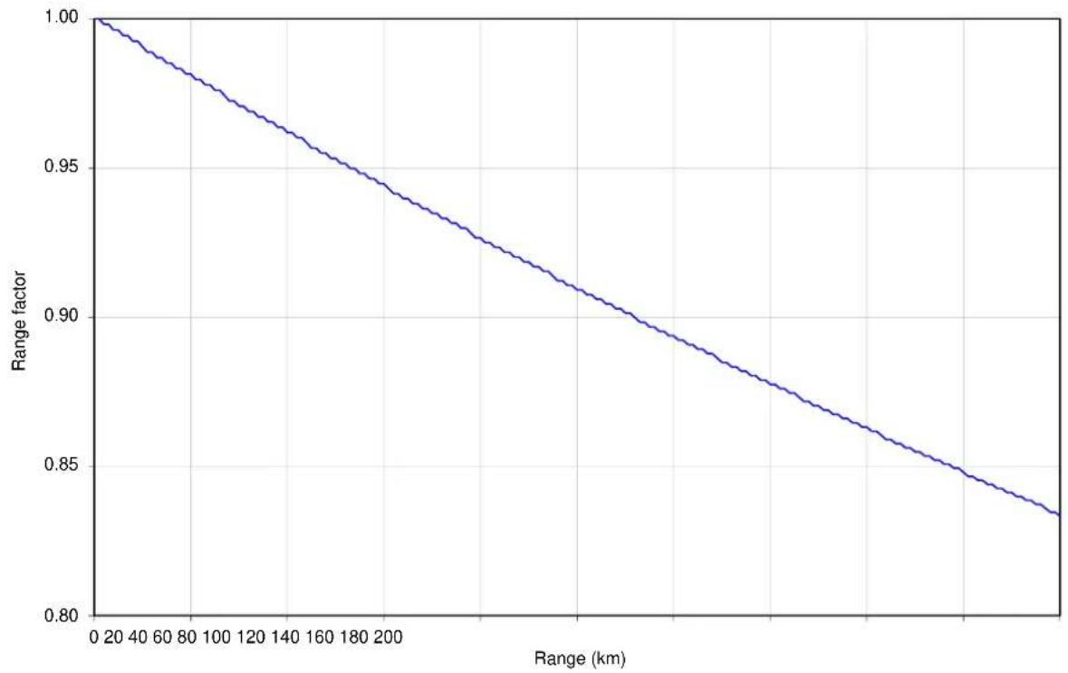
line
| Range (km) | Range factor | | ---------- | ------------ | | 0 | 1.00 | | 40 | 0.98 | | 80 | 0.96 | | 120 | 0.94 | | 160 | 0.92 | | 200 | 0.90 | | 240 | 0.88 | | 280 | 0.86 | | 320 | 0.84 | | 360 | 0.82 | | 400 | 0.80 |Figure 84 Range adjustment for PTP 700, symmetry 2:1, optimization IP, bandwidth 40 MHz

line
| Range (km) | Range factor | | ---------- | ------------ | | 0 | 1.00 | | 40 | 0.98 | | 80 | 0.96 | | 120 | 0.94 | | 160 | 0.92 | | 200 | 0.90 | | 240 | 0.88 | | 280 | 0.86 | | 320 | 0.84 | | 360 | 0.82 | | 400 | 0.80 |Figure 85 Range adjustment for PTP 700, symmetry 2:1, optimization IP, bandwidth 30 MHz

line
| Range (km) | Range factor | | ---------- | ------------ | | 0 | 1.00 | | 40 | 0.98 | | 80 | 0.96 | | 120 | 0.94 | | 160 | 0.92 | | 200 | 0.90 | | 240 | 0.88 | | 280 | 0.86 | | 320 | 0.84 | | 360 | 0.82 | | 400 | 0.80 | | 440 | 0.78 | | 480 | 0.76 | | 520 | 0.74 | | 560 | 0.72 | | 600 | 0.71 |Figure 86 Range adjustment for PTP 700, symmetry 2:1, optimization IP, bandwidth 20 MHz
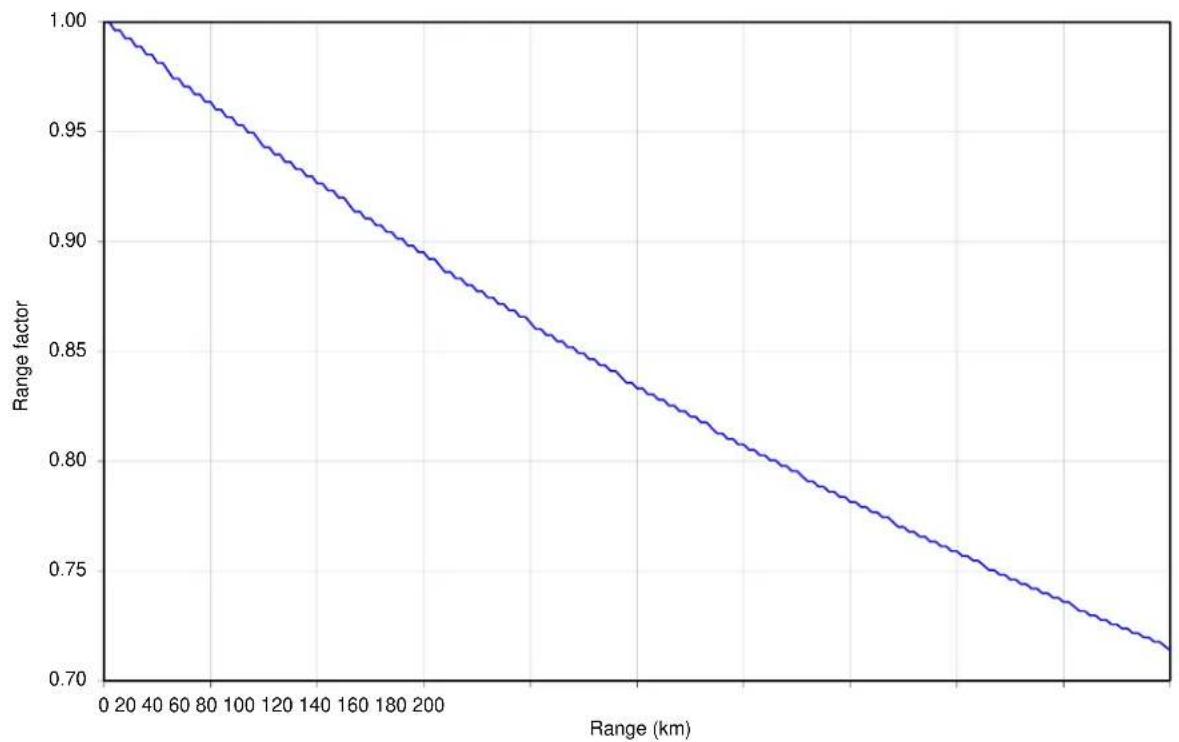
line
| Range (km) | Range factor | | ---------- | ------------ | | 0 | 1.00 | | 40 | 0.98 | | 80 | 0.96 | | 120 | 0.94 | | 160 | 0.92 | | 200 | 0.90 | | 240 | 0.88 | | 280 | 0.86 | | 320 | 0.84 | | 360 | 0.82 | | 400 | 0.80 | | 440 | 0.78 | | 480 | 0.76 | | 520 | 0.74 | | 560 | 0.72 | | 600 | 0.71 |Figure 87 Range adjustment for PTP 700, symmetry 2:1, optimization IP, bandwidth 15 MHz
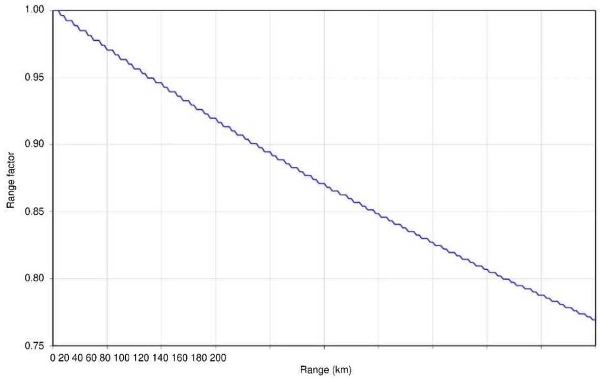
line
| Range (km) | Range factor | | ---------- | ------------ | | 0 | 1.00 | | 40 | 0.98 | | 80 | 0.96 | | 120 | 0.94 | | 160 | 0.92 | | 200 | 0.90 | | 240 | 0.88 | | 280 | 0.86 | | 320 | 0.84 | | 360 | 0.82 | | 400 | 0.80 | | 440 | 0.78 | | 480 | 0.76 |Figure 88 Range adjustment for PTP 700, symmetry 2:1, optimization IP, bandwidth 10 MHz

line
| Range (km) | Range factor | | ---------- | ------------ | | 0 | 1.00 | | 20 | 0.99 | | 40 | 0.98 | | 60 | 0.97 | | 80 | 0.96 | | 100 | 0.95 | | 120 | 0.94 | | 140 | 0.93 | | 160 | 0.92 | | 180 | 0.91 | | 200 | 0.90 | | 220 | 0.89 | | 240 | 0.88 | | 260 | 0.87 | | 280 | 0.86 | | 300 | 0.85 | | 320 | 0.84 | | 340 | 0.83 | | 360 | 0.82 | | 380 | 0.81 | | 400 | 0.80 | | 420 | 0.79 | | 440 | 0.78 | | 460 | 0.77 | | 480 | 0.76 | | 500 | 0.75 | | 520 | 0.74 | | 540 | 0.73 | | 560 | 0.72 | | 580 | 0.71 | | 600 | 0.70 |Figure 89 Range adjustment for PTP 700, symmetry 2:1, optimization TDM, bandwidth 45 MHz

line
| Range (km) | Range factor | | ---------- | ------------ | | 0 | 1.00 | | 40 | 0.97 | | 80 | 0.94 | | 120 | 0.91 | | 160 | 0.88 | | 200 | 0.85 | | 240 | 0.82 | | 280 | 0.79 | | 320 | 0.76 | | 360 | 0.73 | | 400 | 0.70 | | 440 | 0.67 | | 480 | 0.65 | | 520 | 0.66 | | 560 | 0.68 | | 600 | 0.70 | | 640 | 0.72 | | 680 | 0.74 | | 720 | 0.76 | | 760 | 0.78 | | 800 | 0.80 | | 840 | 0.82 | | 880 | 0.84 | | 920 | 0.86 | | 960 | 0.88 | | 1000 | 0.90 | | 1040 | 0.92 | | 1080 | 0.94 | | 1120 | 0.96 | | 1160 | 0.98 | | 1200 | 1.00 |Figure 90 Range adjustment for PTP 700, symmetry 2:1, optimization TDM, bandwidth 40 MHz

line
| Range (km) | Range factor | | ---------- | ------------ | | 0 | 1.00 | | 20 | 0.98 | | 40 | 0.96 | | 60 | 0.94 | | 80 | 0.92 | | 100 | 0.90 | | 120 | 0.88 | | 140 | 0.86 | | 160 | 0.84 | | 180 | 0.82 | | 200 | 0.80 | | 220 | 0.78 | | 240 | 0.76 | | 260 | 0.74 | | 280 | 0.72 | | 300 | 0.70 | | 320 | 0.68 | | 340 | 0.66 | | 360 | 0.65 | | 380 | 0.66 | | 400 | 0.67 | | 420 | 0.68 | | 440 | 0.69 | | 460 | 0.70 | | 480 | 0.71 | | 500 | 0.72 | | 520 | 0.73 | | 540 | 0.74 | | 560 | 0.75 | | 580 | 0.76 | | 600 | 0.77 | | 620 | 0.78 | | 640 | 0.79 | | 660 | 0.80 | | 680 | 0.81 | | 700 | 0.82 | | 720 | 0.83 | | 740 | 0.84 | | 760 | 0.85 | | 780 | 0.86 | | 800 | 0.87 | | 820 | 0.88 | | 840 | 0.89 | | 860 | 0.90 | | 880 | 0.91 | | 900 | 0.92 | | 920 | 0.93 | | 940 | 0.94 | | 960 | 0.95 | | 980 | 0.96 | | 1000 | 0.97 |Figure 91 Range adjustment for PTP 700, symmetry 2:1, optimization TDM, bandwidth 30 MHz

line
| Range (km) | Range factor | | ---------- | ------------ | | 0 | 1.00 | | 20 | 0.98 | | 40 | 0.95 | | 60 | 0.92 | | 80 | 0.89 | | 100 | 0.86 | | 120 | 0.83 | | 140 | 0.80 | | 160 | 0.77 | | 180 | 0.74 | | 200 | 0.71 | | 220 | 0.68 | | 240 | 0.65 | | 260 | 0.80 | | 280 | 0.78 | | 300 | 0.76 | | 320 | 0.74 | | 340 | 0.72 | | 360 | 0.70 | | 380 | 0.68 | | 400 | 0.66 | | 420 | 0.65 | | 440 | 0.64 | | 460 | 0.63 | | 480 | 0.62 | | 500 | 0.61 |Figure 92 Range adjustment for PTP 700, symmetry 2:1, optimization TDM, bandwidth 20 MHz

Figure 93 Range adjustment for PTP 700, symmetry 2:1, optimization TDM, bandwidth 15 MHz
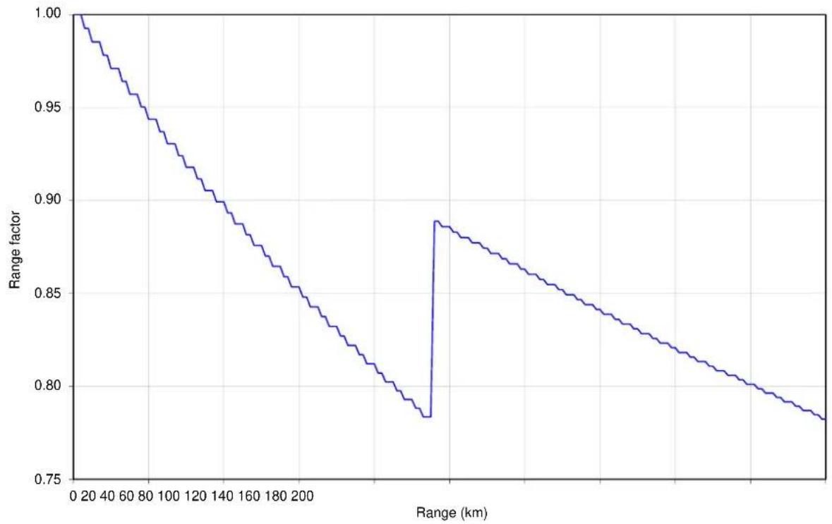
line
| Range (km) | Range factor | | ---------- | ------------ | | 0 | 1.00 | | 20 | 0.98 | | 40 | 0.96 | | 60 | 0.94 | | 80 | 0.92 | | 100 | 0.90 | | 120 | 0.88 | | 140 | 0.86 | | 160 | 0.84 | | 180 | 0.82 | | 200 | 0.80 | | 220 | 0.78 | | 240 | 0.78 | | 260 | 0.78 | | 280 | 0.78 | | 300 | 0.78 | | 320 | 0.78 | | 340 | 0.78 | | 360 | 0.78 | | 380 | 0.78 | | 400 | 0.78 | | 420 | 0.78 | | 440 | 0.78 | | 460 | 0.78 | | 480 | 0.78 | | 500 | 0.78 |Figure 94 Range adjustment for PTP 700, symmetry 2:1, optimization TDM, bandwidth 10 MHz
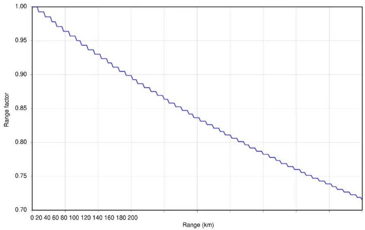
line
| Range (km) | Range factor | | ---------- | ------------ | | 0 | 1.00 | | 20 | 0.99 | | 40 | 0.98 | | 60 | 0.97 | | 80 | 0.96 | | 100 | 0.95 | | 120 | 0.94 | | 140 | 0.93 | | 160 | 0.92 | | 180 | 0.91 | | 200 | 0.90 | | 220 | 0.89 | | 240 | 0.88 | | 260 | 0.87 | | 280 | 0.86 | | 300 | 0.85 | | 320 | 0.84 | | 340 | 0.83 | | 360 | 0.82 | | 380 | 0.81 | | 400 | 0.80 | | 420 | 0.79 | | 440 | 0.78 | | 460 | 0.77 | | 480 | 0.76 | | 500 | 0.75 | | 520 | 0.74 | | 540 | 0.73 | | 560 | 0.72 | | 580 | 0.71 | | 600 | 0.70 |Figure 95 Range adjustment for PTP 700, symmetry 3:1, optimization IP, bandwidth 45 MHz

line
| Range (km) | Range factor | | ---------- | ------------ | | 0 | 1.00 | | 40 | 0.98 | | 80 | 0.96 | | 120 | 0.94 | | 160 | 0.92 | | 200 | 0.90 | | 240 | 0.88 | | 280 | 0.86 | | 320 | 0.84 | | 360 | 0.82 | | 400 | 0.80 | | 440 | 0.78 | | 480 | 0.76 | | 520 | 0.74 | | 560 | 0.72 | | 600 | 0.70 | | 640 | 0.69 |Figure 96 Range adjustment for PTP 700, symmetry 3:1, optimization IP, bandwidth 40 MHz

line
| Range (km) | Range factor | | ---------- | ------------ | | 0 | 1.00 | | 40 | 0.98 | | 80 | 0.96 | | 120 | 0.94 | | 160 | 0.92 | | 200 | 0.90 | | 240 | 0.88 | | 280 | 0.86 | | 320 | 0.84 | | 360 | 0.82 | | 400 | 0.80 | | 440 | 0.78 | | 480 | 0.76 | | 520 | 0.74 | | 560 | 0.72 | | 600 | 0.71 |Figure 97 Range adjustment for PTP 700, symmetry 3:1, optimization IP, bandwidth 30 MHz

line
| Range (km) | Range factor | | ---------- | ------------ | | 0 | 1.00 | | 40 | 0.98 | | 80 | 0.96 | | 120 | 0.94 | | 160 | 0.92 | | 200 | 0.90 | | 240 | 0.88 | | 280 | 0.86 | | 320 | 0.84 | | 360 | 0.82 | | 400 | 0.80 | | 440 | 0.78 | | 480 | 0.76 | | 520 | 0.74 | | 560 | 0.72 | | 600 | 0.70 | | 640 | 0.69 |Figure 98 Range adjustment for PTP 700, symmetry 3:1, optimization IP, bandwidth 20 MHz

line
| Range (km) | Range factor | | ---------- | ------------ | | 0 | 1.00 | | 40 | 0.97 | | 80 | 0.94 | | 120 | 0.91 | | 160 | 0.88 | | 200 | 0.85 | | 240 | 0.82 | | 280 | 0.79 | | 320 | 0.76 | | 360 | 0.73 | | 400 | 0.70 | | 440 | 0.67 | | 480 | 0.65 | | 520 | 0.63 |Figure 99 Range adjustment for PTP 700, symmetry 3:1, optimization IP, bandwidth 15 MHz

line
| Range (km) | Range factor | | ---------- | ------------ | | 0 | 1.00 | | 40 | 0.98 | | 80 | 0.96 | | 120 | 0.94 | | 160 | 0.92 | | 200 | 0.90 | | 240 | 0.88 | | 280 | 0.86 | | 320 | 0.84 | | 360 | 0.82 | | 400 | 0.80 | | 440 | 0.78 | | 480 | 0.76 | | 520 | 0.74 | | 560 | 0.72 | | 600 | 0.70 | | 640 | 0.69 |Figure 100 Range adjustment for PTP 700, symmetry 3:1, optimization IP, bandwidth 10 MHz

line
| Range (km) | Range factor | | ---------- | ------------ | | 0 | 1.00 | | 20 | 0.99 | | 40 | 0.98 | | 60 | 0.97 | | 80 | 0.96 | | 100 | 0.95 | | 120 | 0.94 | | 140 | 0.93 | | 160 | 0.92 | | 180 | 0.91 | | 200 | 0.90 | | 220 | 0.89 | | 240 | 0.88 | | 260 | 0.87 | | 280 | 0.86 | | 300 | 0.85 | | 320 | 0.84 | | 340 | 0.83 | | 360 | 0.82 | | 380 | 0.81 | | 400 | 0.80 | | 420 | 0.79 | | 440 | 0.78 | | 460 | 0.77 | | 480 | 0.76 | | 500 | 0.75 |Figure 101 Range adjustment for PTP 700, symmetry 5:1, optimization IP, bandwidth 45 MHz

line
| Range (km) | Range factor | | ---------- | ------------ | | 0 | 1.00 | | 40 | 0.98 | | 80 | 0.96 | | 120 | 0.94 | | 160 | 0.92 | | 200 | 0.90 | | 240 | 0.88 | | 280 | 0.86 | | 320 | 0.84 | | 360 | 0.82 | | 400 | 0.80 | | 440 | 0.78 | | 480 | 0.76 | | 520 | 0.74 | | 560 | 0.72 | | 600 | 0.70 | | 640 | 0.69 |Figure 102 Range adjustment for PTP 700, symmetry 5:1, optimization IP, bandwidth 40 MHz

line
| Range (km) | Range factor | | ---------- | ------------ | | 0 | 1.00 | | 40 | 0.97 | | 80 | 0.93 | | 120 | 0.89 | | 160 | 0.85 | | 200 | 0.81 | | 240 | 0.77 | | 280 | 0.73 | | 320 | 0.70 | | 360 | 0.67 | | 400 | 0.64 | | 440 | 0.61 | | 480 | 0.58 | | 520 | 0.56 |Figure 103 Range adjustment for PTP 700, symmetry 5:1, optimization IP, bandwidth 30 MHz

line
| Range (km) | Range factor | | ---------- | ------------ | | 0 | 1.00 | | 40 | 0.97 | | 80 | 0.94 | | 120 | 0.91 | | 160 | 0.88 | | 200 | 0.85 | | 240 | 0.82 | | 280 | 0.79 | | 320 | 0.76 | | 360 | 0.73 | | 400 | 0.70 | | 440 | 0.67 | | 480 | 0.64 | | 520 | 0.62 |Figure 104 Range adjustment for PTP 700, adaptive, optimization IP, bandwidth 45 MHz

line
| Range (km) | Range factor | | ---------- | ------------ | | 0 | 1.00 | | 40 | 0.98 | | 80 | 0.96 | | 120 | 0.94 | | 160 | 0.92 | | 200 | 0.90 | | 240 | 0.88 | | 280 | 0.86 | | 320 | 0.84 | | 360 | 0.82 | | 400 | 0.80 |Figure 105 Range adjustment for PTP 700, adaptive, optimization IP, bandwidth 40 MHz

line
| Range (km) | Range factor | | ---------- | ------------ | | 0 | 1.00 | | 40 | 0.98 | | 80 | 0.96 | | 120 | 0.94 | | 160 | 0.92 | | 200 | 0.90 | | 240 | 0.88 | | 280 | 0.86 | | 320 | 0.84 | | 360 | 0.82 | | 400 | 0.80 | | 440 | 0.79 |Figure 106 Range adjustment for PTP 700, adaptive, optimization IP, bandwidth 30 MHz
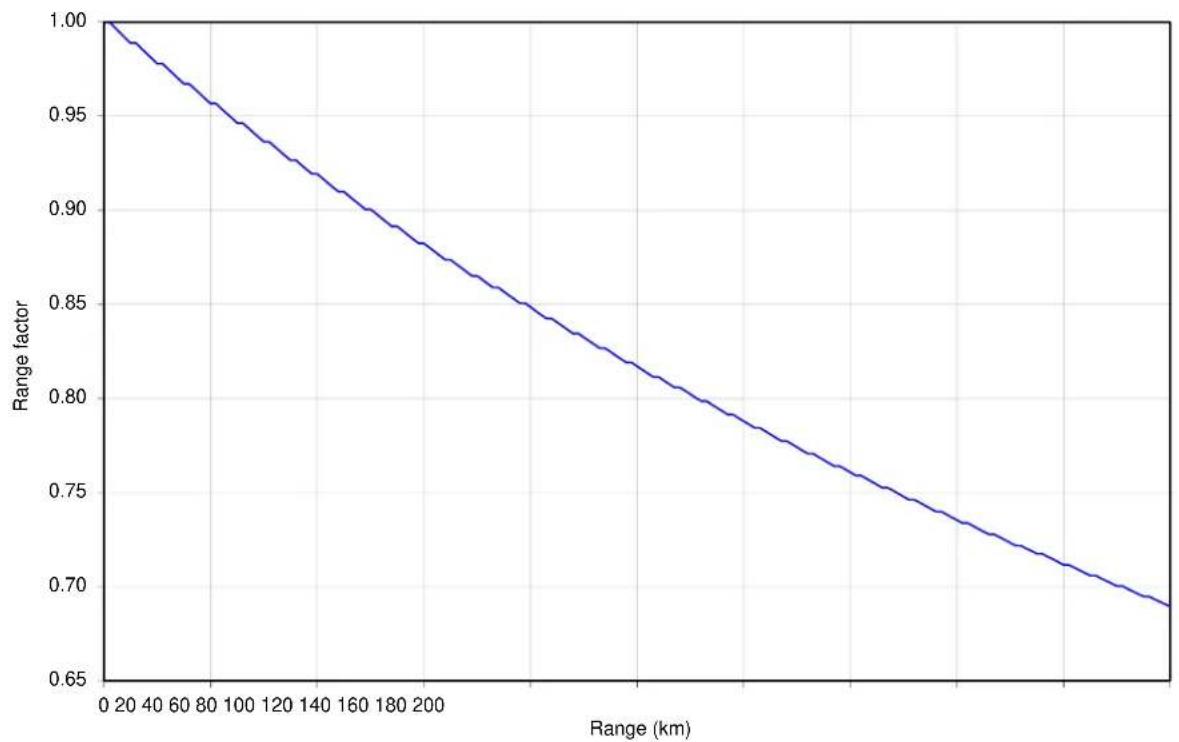
line
| Range (km) | Range factor | | ---------- | ------------ | | 0 | 1.00 | | 40 | 0.98 | | 80 | 0.96 | | 120 | 0.94 | | 160 | 0.92 | | 200 | 0.90 | | 240 | 0.88 | | 280 | 0.86 | | 320 | 0.84 | | 360 | 0.82 | | 400 | 0.80 | | 440 | 0.78 | | 480 | 0.76 | | 520 | 0.74 | | 560 | 0.72 | | 600 | 0.70 | | 640 | 0.69 |Figure 107 Range adjustment for PTP 700, adaptive, optimization IP, bandwidth 20 MHz

line
| Range (km) | Range factor | | ---------- | ------------ | | 0 | 1.00 | | 40 | 0.97 | | 80 | 0.95 | | 120 | 0.93 | | 160 | 0.91 | | 200 | 0.89 | | 240 | 0.87 | | 280 | 0.85 | | 320 | 0.83 | | 360 | 0.81 | | 400 | 0.79 | | 440 | 0.77 | | 480 | 0.75 | | 520 | 0.73 | | 560 | 0.71 | | 600 | 0.69 | | 640 | 0.67 |Figure 108 Range adjustment for PTP 700, adaptive, optimization IP, bandwidth 15 MHz

line
| Range (km) | Range factor | | ---------- | ------------ | | 0 | 1.00 | | 40 | 0.98 | | 80 | 0.96 | | 120 | 0.94 | | 160 | 0.92 | | 200 | 0.90 | | 240 | 0.88 | | 280 | 0.86 | | 320 | 0.84 | | 360 | 0.82 | | 400 | 0.80 | | 440 | 0.78 | | 480 | 0.76 | | 520 | 0.74 | | 560 | 0.73 |Figure 109 Range adjustment for PTP 700, adaptive, optimization IP, bandwidth 10 MHz
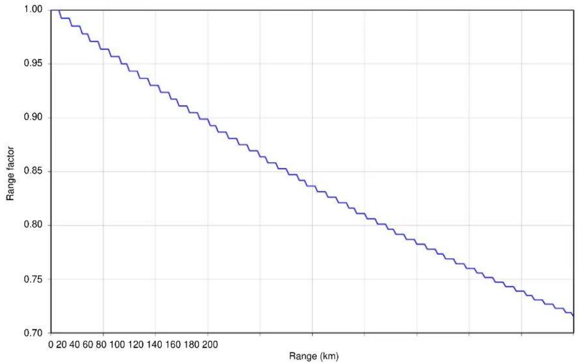
line
| Range (km) | Range factor | | ---------- | ------------ | | 0 | 1.00 | | 20 | 0.99 | | 40 | 0.98 | | 60 | 0.97 | | 80 | 0.96 | | 100 | 0.95 | | 120 | 0.94 | | 140 | 0.93 | | 160 | 0.92 | | 180 | 0.91 | | 200 | 0.90 | | 220 | 0.89 | | 240 | 0.88 | | 260 | 0.87 | | 280 | 0.86 | | 300 | 0.85 | | 320 | 0.84 | | 340 | 0.83 | | 360 | 0.82 | | 380 | 0.81 | | 400 | 0.80 | | 420 | 0.79 | | 440 | 0.78 | | 460 | 0.77 | | 480 | 0.76 | | 500 | 0.75 | | 520 | 0.74 | | 540 | 0.73 | | 560 | 0.72 | | 580 | 0.71 | | 600 | 0.70 |Time slots per frame in PTP topology with synchronization
Use the tables in this section to look up the number of time slots per TDD frame in PTP topology with TDD synchronization, including links with Hot Standby protection. Use this information with the capacity per time slot in Table 159 to calculate link capacity in each direction.
PTP topology with standard frame duration
Table 153 Number of time slots in synchronized PTP links
| Channel Bandwidth | Burst Duration | Number of time slots |
| 10 MHz | 1088 Qs | 1 |
| 2176 Qs | 2 | |
| 15 MHz | 726 Qs | 1 |
| 1451 Qs | 2 | |
| 2176 Qs | 3 | |
| 20 MHz | 544 Qs | 1 |
| 1088 Qs | 2 | |
| 1632 Qs | 3 | |
| 2176 Qs | 4 | |
| 30 MHz | 726 Qs | 2 |
| 1088 Qs | 3 | |
| 1453 Qs | 4 | |
| 2176 Qs | 6 | |
| 40 MHz | 544 Qs | 2 |
| 816 Qs | 3 | |
| 1088 Qs | 4 | |
| 1632 Qs | 6 | |
| 2176 Qs | 8 | |
| 45 MHz | 484 Qs | 2 |
| 726 Qs | 3 | |
| 970 Qs | 4 | |
| 1453 Qs | 6 | |
| 1937 Qs | 8 |
PTP topology with long frame duration
Table 154 Number of time slots in synchronized PTP links with long frame duration
| Channel Bandwidth | Burst Duration | Number of time slots | |
| Unprotected | Hot Standby | ||
| 20 MHz | 1088 Qs | 2 | 1 |
| 1632 Qs | 3 | 2 | |
| 2176 Qs | 4 | 3 | |
| 2720 μs | 5 | 4 | |
| 3264 μs | 6 | 5 | |
| 3808 μs | 7 | 6 | |
| 4352 μs | 8 | 7 | |
| 4896 μs | 9 | 8 | |
| 5440 μs | 10 | 9 | |
| 5984 μs | 11 | 10 | |
| 6528 μs | 12 | 11 | |
| 30 MHz | 726 μs | 2 | 1 |
| 1088 μs | 3 | 2 | |
| 1451 μs | 4 | 3 | |
| 1814 μs | 5 | 4 | |
| 2176 μs | 6 | 5 | |
| 2539 μs | 7 | 6 | |
| 2902 μs | 8 | 7 | |
| 3264 μs | 9 | 8 | |
| 3627 μs | 10 | 9 | |
| 3990 μs | 11 | 10 | |
| 4352 μs | 12 | 11 | |
| 4715 μs | 13 | 12 | |
| 5078 μs | 14 | 13 | |
| 5440 μs | 15 | 14 | |
| 40 MHz | 532 μs | 2 | 1 |
| 798 μs | 3 | 2 | |
| 1064 μs | 4 | 3 | |
| 1330 μs | 5 | 4 | |
| 1596 μs | 6 | 5 | |
| 1862 μs | 7 | 6 | |
| 2128 μs | 8 | 7 | |
| 2394 μs | 9 | 8 | |
| 2660 μs | 10 | 9 | |
| 2926 μs | 11 | 10 | |
| 3192 μs | 12 | 11 | |
| 3458 μs | 13 | 12 | |
| 3724 μs | 14 | 13 | |
| 3990 μs | 15 | 14 | |
| 45 MHz | 486 μs | 2 | 1 |
| 728 μs | 3 | 2 | |
| 971 μs | 4 | 3 | |
| 1214 μs | 5 | 4 | |
| 1456 μs | 6 | 5 | |
| 1699 μs | 7 | 6 | |
| 1942 μs | 8 | 7 | |
| 2184 μs | 9 | 8 | |
| 2427 μs | 10 | 9 | |
| 2670 μs | 11 | 10 | |
| 2912 μs | 12 | 11 | |
| 3155 μs | 13 | 12 | |
| 3398 μs | 14 | 13 | |
| 3640 μs | 15 | 14 | |
Frame duration in HCMP topology with standard configuration
Use the tables in this section to look up the TDD frame duration as a function of bandwidth, number of Slaves and Link Symmetry. Then look up one-way capacity (Mbit/s) achieved in each time slot of an HCMP sector as a function of frame duration and modulation mode.
The one-way capacity for a single Slave is the capacity per time slot multiplied by the number of time slots. The aggregate (two-way) capacity for one Slave is the sum of two one-way capacities. The aggregate capacity for the Master is the capacity for one Slave multiplied by the number of Slaves.
Determine the frame duration from the following tables:
Table 155 HCMP frame duration table of tables
| Channel Bandwidth | TDD Synchronization | Frame Duration Table | Capacity Table |
| 20 MHz | Disabled | Table 156 | Table 159 |
| Enabled | |||
| 40 MHz | Disabled | Table 157 | |
| Enabled | Table 158 |
Table 156 HCMP frame duration, 20 MHz Channel Bandwidth
| Number of Slaves | Link symmetry | Maximum range | Frame Duration |
| Two | 1:1 | 5.0 km to 16.3 km | 2882 Qs |
| 16.4 km to 32.6 km | 3012 Qs | ||
| 32.7 km to 57.0 km | 3145 Qs | ||
| 57.1 km to 81.5 km | 3311 Qs | ||
| 81.6 km to 97.8 km | 3460 Qs | ||
| 97.9 km to 100.0 km | 3610 Qs | ||
| 1:2 and 2:1 | 5.0 km to 16.3 km | 4184 Qs | |
| 16.4 km to 40.7 km | 4367 Qs | ||
| 40.8 km to 73.3 km | 4566 Qs | ||
| 73.4 km to 100.0 km | 4785 Qs | ||
| 1:3 and 3:1 | 5.0 km to 16.3 km | 5495 Qs | |
| 16.4 km to 48.9 km | 5714 Qs | ||
| 49.0 km to 97.8 km | 6024 Qs | ||
| 97.9 km to 100.0 km | 6410 Qs | ||
| 1:4 and 4:1 | 5.0 km to 24.4 km | 6849 Qs | |
| 24.5 km to 65.2 km | 7143 Qs | ||
| 65.3 km to 100.0 km | 8065 Qs | ||
| Three | 1:1 | 5.0 km to 16.3 km | 4184 Qs |
| 16.4 km to 40.7 km | 4367 Qs | ||
| 40.8 km to 73.3 km | 4566 Qs | ||
| 73.4 km to 100.0 km | 4785 Qs | ||
| 1:2 and 2:1 | 5.0 km to 57.0 km | 6410 Qs | |
| 57.1 km to 100.0 km | 6849 Qs | ||
| 1:3 and 3:1 | 5.0 km to 8.1 km | 8065 Qs | |
| 8.2 km to 81.5 km | 8547 Qs | ||
| 81.6 km to 100.0 km | 9259 Qs | ||
| 1:4 and 4:1 | 5.0 km to 8.1 km | 10000 Qs | |
| 8.2 km to 81.5 km | 10526 Qs | ||
| 81.6 km to 100.0 km | 10989 Qs | ||
| Four | 1:1 | 5.0 km to 16.3 km | 5495 Qs |
| 16.4 km to 48.9 km | 5714 Qs | ||
| 49.0 km to 97.8 km | 6024 Qs | ||
| 97.9 km to 100.0 km | 6410 Qs | ||
| 1:2 and 2:1 | 5.0 km to 8.1 km | 8065 Qs | |
| 8.2 km to 81.5 km | 8547 Qs | ||
| 81.6 km to 100.0 km | 9259 Qs | ||
| 1:3 and 3:1 | 5.0 km to 57.0 km | 10989 Qs | |
| 57.1 km to 100.0 km | 11628 Qs | ||
| 1:4 and 4:1 | 5.0 km to 40.7 km | 13514 Qs | |
| 40.8 km to 100.0 km | 14286 Qs | ||
| Five | 1:1 | 5.0 km to 24.4 km | 6849 Qs |
| 24.5 km to 65.2 km | 7143 Qs | ||
| 65.3 km to 100.0 km | 8065 Qs | ||
| 1:2 and 2:1 | 5.0 km to 8.1 km | 10000 Qs | |
| 8.2 km to 81.5 km | 10526 Qs | ||
| 81.6 km to 100.0 km | 10989 Qs | ||
| 1:3 and 3:1 | 5.0 km to 40.7 km | 13514 Qs | |
| 40.8 km to 100.0 km | 14286 Qs | ||
| Six | 1:1 | 5.0 km to 8.1 km | 8065 Qs |
| 8.2 km to 81.5 km | 8547 Qs | ||
| 81.6 km to 100.0 km | 9259 Qs | ||
| 1:2 and 2:1 | 5.0 km to 40.7 km | 12195 Qs | |
| 40.8 km to 100.0 km | 13514 Qs | ||
| Seven | 1:1 | 5.0 km to 32.6 km | 9524 Qs |
| 32.7 km to 100.0 km | 10000 Qs | ||
| 1:2 and 2:1 | 5.0 km to 57.0 km | 14286 Qs | |
| Eight | 1:1 | 5.0 km to 57.0 km | 10989 Qs |
| 57.1 km to 100.0 km | 11628 Qs |
Table 157 HCMP frame duration, 40 MHz Channel Bandwidth, without TDD Sync
| Number of Slaves | Link symmetry | Maximum range | Frame Duration |
| Two | 1:1 | 5.0 km to 7.9 km | 1439 Qs |
| 8.0 km to 15.9 km | 1504 Qs | ||
| 16.0 km to 27.9 km | 1575 Qs | ||
| 28.0 km to 31.8 km | 1623 Qs | ||
| 31.9 km to 39.8 km | 1650 Qs | ||
| 39.9 km to 51.8 km | 1730 Qs | ||
| 51.9 km to 59.7 km | 1805 Qs | ||
| 59.8 km to 67.7 km | 1859 Qs | ||
| 67.8 km to 75.7 km | 1908 Qs | ||
| 75.8 km to 91.6 km | 2000 Qs | ||
| 91.7 km to 100.0 km | 2079 Qs | ||
| 2:1 | 5.0 km to 7.9 km | 2079 Qs | |
| 8.0 km to 19.9 km | 2179 Qs | ||
| 20.0 km to 35.8 km | 2283 Qs | ||
| 35.9 km to 51.8 km | 2392 Qs | ||
| 51.9 km to 67.7 km | 2500 Qs | ||
| 67.8 km to 87.6 km | 2618 Qs | ||
| 87.7 km to 100.0 km | 2747 Qs | ||
| 3:1 | 5.0 km to 11.9 km | 2747 Qs | |
| 12.0 km to 31.8 km | 2882 Qs | ||
| 31.9 km to 51.8 km | 3012 Qs | ||
| 51.9 km to 71.7 km | 3145 Qs | ||
| 71.8 km to 95.6 km | 3311 Qs | ||
| 95.7 km to 100.0 km | 3460 Qs | ||
| 4:1 | 5.0 km to 19.9 km | 3460 Qs | |
| 20.0 km to 43.8 km | 3610 Qs | ||
| 43.9 km to 75.7 km | 3817 Qs | ||
| 75.8 km to 100.0 km | 4000 Qs | ||
| Three | 1:1 | 5.0 km to 7.9 km | 2079 Qs |
| 8.0 km to 19.9 km | 2179 Qs | ||
| 20.0 km to 35.8 km | 2283 Qs | ||
| 35.9 km to 51.8 km | 2392 Qs | ||
| 51.8 km to 67.7 km | 2500 Qs | ||
| 67.8 km to 87.6 km | 2618 Qs | ||
| 87.7 km to 100.0 km | 2747 Qs | ||
| 2:1 | 5.0 km to 19.9 km | 3145 Qs | |
| 20.0 km to 47.8 km | 3311 Qs | ||
| 47.9 km to 67.7 km | 3460 Qs | ||
| 67.8 km to 91.6 km | 3610 Qs | ||
| 91.7 km to 100.0 km | 3817 Qs | ||
| 3:1 | 5.0 km to 7.9 km | 4000 Qs | |
| 8.0 km to 31.8 km | 4184 Qs | ||
| 31.9 km to 59.7 km | 4367 Qs | ||
| 59.8 km to 91.6 km | 4566 Qs | ||
| 91.7 km to 100.0 km | 4785 Qs | ||
| 4:1 | 5.0 km to 11.9 km | 5000 Qs | |
| 12.0 km to 47.8 km | 5236 Qs | ||
| 47.9 km to 87.6 km | 5495 Qs | ||
| 87.7 km to 100.0 km | 5714 Qs | ||
| Four | 1:1 | 5.0 km to 11.9 km | 2747 Qs |
| 12.0 km to 31.8 km | 2882 Qs | ||
| 31.9 km to 51.8 km | 3012 Qs | ||
| 51.9 km to 71.7 km | 3145 Qs | ||
| 71.8 km to 95.6 km | 3311 Qs | ||
| 95.7 km to 100.0 km | 3460 Qs | ||
| 2:1 | 5.0 km to 7.9 km | 4000 Qs | |
| 8.0 km to 31.8 km | 4184 Qs | ||
| 31.9 km to 59.7 km | 4367 Qs | ||
| 59.8 km to 91.6 km | 4566 Qs | ||
| 91.6 km to 100.0 km | 4785 Qs | ||
| 3:1 | 5.0 km to 39.8 km | 5495 Qs | |
| 39.9 km to 71.7 km | 5714 Qs | ||
| 71.8 km to 100.0 km | 6024 Qs | ||
| 4:1 | 5.0 km to 47.8 km | 6849 Qs | |
| 47.9 km to 91.6 km | 7143 Qs | ||
| 91.7 km to 100.0 km | 8065 Qs | ||
| Five | 1:1 | 5.0 km to 19.9 km | 3460 Qs |
| 20.0 km to 43.8 km | 3610 Qs | ||
| 43.9 km to 75.7 km | 3817 Qs | ||
| 75.8 km to 100.0 km | 4000 Qs | ||
| 2:1 | 5.0 km to 11.9 km | 5000 Qs | |
| 12.0 km to 47.8 km | 5236 Qs | ||
| 47.9 km to 87.6 km | 5495 Qs | ||
| 87.7 km to 100.0 km | 5714 Qs | ||
| 3:1 | 5.0 km to 47.8 km | 6849 Qs | |
| 47.9 km to 91.6 km | 7143 Qs | ||
| 91.7 km to 100.0 km | 8065 Qs | ||
| 4:1 | 5.0 km to 63.7 km | 8547 Qs | |
| 63.8 km to 100.0 km | 9259 Qs | ||
| Six | 1:1 | 5.0 km to 7.9 km | 4000 Qs |
| 8.0 km to 31.8 km | 4184 Qs | ||
| 31.9 km to 59.7 km | 4367 Qs | ||
| 59.8 km to 91.6 km | 4566 Qs | ||
| 91.7 km to 100.0 km | 4785 Qs | ||
| 2:1 | 5.0 km to 19.9 km | 6024 Qs | |
| 20.0 km to 79.7 km | 6410 Qs | ||
| 79.8 km to 100.0 km | 6849 Qs | ||
| 3:1 | 5.0 km to 39.8 km | 8065 Qs | |
| 39.9 km to 100.0 km | 8547 Qs | ||
| 4:1 | 5.0 km to 39.8 km | 10000 Qs | |
| 39.9 km to 100.0 km | 10526 Qs | ||
| Seven | 1:1 | 5.0 km to 27.9 km | 4785 Qs |
| 28.0 km to 59.7 km | 5000 Qs | ||
| 59.8 km to 95.6 km | 5236 Qs | ||
| 95.7 km to 100.0 km | 5495 Qs | ||
| 2:1 | 5.0 km to 43.8 km | 7143 Qs | |
| 43.9 km to 100.0 km | 8065 Qs | ||
| 3:1 | 5.0 km to 27.9 km | 9259 Qs | |
| 28.0 km to 63.7 km | 9524 Qs | ||
| 63.8 km to 100.0 km | 10000 Qs | ||
| 4:1 | 5.0 km to 43.8 km | 11628 Qs | |
| 43.9 km to 100.0 km | 12195 Qs | ||
| Eight | 1:1 | 5.0 km to 39.8 km | 5495 Qs |
| 39.9 km to 71.7 km | 5714 Qs | ||
| 71.8 km to 100.0 km | 6024 Qs | ||
| 2:1 | 5.0 km to 39.8 km | 8065 Qs | |
| 39.9 km to 100.0 km | 8547 Qs | ||
| 3:1 | 5.0 km to 23.9 km | 10526 Qs | |
| 24.0 km to 91.6 km | 10989 Qs | ||
| 91.7 km to 100.0 km | 11628 Qs | ||
| 4:1 | 5.0 km to 87.6 km | 13514 Qs | |
| 87.7 km to 100.0 km | 14286 Qs |
Table 158 HCMP frame duration, 40 MHz Channel Bandwidth, with TDD Sync
| Number of Slaves | Link symmetry | Maximum range | Frame Duration |
| Two | 1:1 | 5.0 km to 91.6 km | 2000 Qs |
| 91.7 km to 100.0 km | 2283 Qs | ||
| 2:1 | 5.0 km to 35.8 km | 2283 Qs | |
| 35.9 km to 100.0 km | 2747 Qs | ||
| 3:1 | 5.0 km to 11.9 km | 2747 Qs | |
| 12.0 km to 100.0 km | 4000 Qs | ||
| 4:1 | 5.0 km to 100.0 km | 4000 Qs | |
| Three | 1:1 | 5.0 km to 35.8 km | 2283 Qs |
| 35.9 km to 100.0 km | 2747 Qs | ||
| 2:1 | 5.0 km to 100.0 km | 4000 Qs | |
| 3:1 | 5.0 km to 7.9 km | 4000 Qs | |
| 8.0 km to 31.8 km | 4184 Qs | ||
| 31.9 km to 91.6 km | 4566 Qs | ||
| 91.7 km to 100.0 km | 5495 Qs | ||
| 4:1 | 5.0 km to 87.6 km | 5495 Qs | |
| 87.7 km to 100.0 km | 6024 Qs | ||
| Four | 1:1 | 5.0 km to 11.9 km | 2747 Qs |
| 12.0 km to 100.0 km | 4000 Qs | ||
| 2:1 | 5.0 km to 7.9 km | 4000 Qs | |
| 8.0 km to 31.8 km | 4184 Qs | ||
| 31.9 km to 91.6 km | 4566 Qs | ||
| 91.7 km to 100.0 km | 5495 Qs | ||
| 3:1 | 5.0 km to 39.8 km | 5495 Qs | |
| 39.9 km to 100.0 km | 6024 Qs | ||
| 4:1 | 5.0 km to 47.8 km | 6849 Qs | |
| 47.9 km to 91.6 km | 7143 Qs | ||
| 91.7 km to 100.0 km | 8065 Qs | ||
| Five | 1:1 | 5.0 km to 100.0 km | 4000 Qs |
| 2:1 | 5.0 km to 87.6 km | 5495 Qs | |
| 87.7 km to 100.0 km | 6024 Qs | ||
| 3:1 | 5.0 km to 47.8 km | 6849 Qs | |
| 47.9 km to 91.6 km | 7143 Qs | ||
| 91.7 km to 100.0 km | 8065 Qs | ||
| 4:1 | 5.0 km to 63.7 km | 8547 Qs | |
| 63.8 km to 100.0 km | 9259 Qs | ||
| Six | 1:1 | 5.0 km to 7.9 km | 4000 Qs |
| 8.0 km to 31.8 km | 4184 Qs | ||
| 31.9 km to 91.6 km | 4566 Qs | ||
| 91.7 km to 100.0 km | 5495 Qs | ||
| 2:1 | 5.0 km to 19.9 km | 6024 Qs | |
| 20.0 km to 79.7 km | 6410 Qs | ||
| 79.8 km to 100.0 km | 6849 Qs | ||
| 3:1 | 5.0 km to 39.8 km | 8065 Qs | |
| 39.9 km to 100.0 km | 8547 Qs | ||
| 4:1 | 5.0 km to 39.8 km | 10000 Qs | |
| 39.9 km to 100.0 km | 10526 Qs | ||
| Seven | 1:1 | 5.0 km to 100.0 km | 5495 Qs |
| 2:1 | 5.0 km to 43.8 km | 7143 Qs | |
| 43.9 km to 100.0 km | 8065 Qs | ||
| 3:1 | 5.0 km to 27.9 km | 9259 Qs | |
| 28.0 km to 63.7 km | 9524 Qs | ||
| 63.8 km to 100.0 km | 10000 Qs | ||
| 4:1 | 5.0 km to 43.8 km | 11628 Qs | |
| 43.9 km to 100.0 km | 12195 Qs | ||
| Eight | 1:1 | 5.0 km to 39.8 km | 5495 Qs |
| 39.9 km to 100.0 km | 6024 Qs | ||
| 2:1 | 5.0 km to 39.8 km | 8065 Qs | |
| 39.9 km to 100.0 km | 8547 Qs | ||
| 3:1 | 5.0 km to 23.9 km | 10526 Qs | |
| 24.0 km to 91.6 km | 10989 Qs | ||
| 91.7 km to 100.0 km | 11628 Qs | ||
| 4:1 | 5.0 km to 87.6 km | 13514 Qs | |
| 87.7 km to 100.0 km | 14286 Qs |
Frame duration in HCMP topology with expert configuration
When TDD Frame Configuration Mode is set to Expert Mode, the ODU is configured by setting the maximum link range in the Wireless Configuration page of the Installation Wizard and selecting the number of time slots reserved for uplink and downlink directions in the TDD Frame page. The ODU calculates the TDD Frame Duration and displays this in the TDD Synchronization page of the Installation Wizard. TDD Frame Duration depends on:
- Channel Bandwidth
• Maximum Range
• TDD Synchronization
• Number of Uplink Time Slots at the Master
• Number of Downlink Time Slots at the Master
Frame Duration in HCMP Frame Configuration Expert Mode can be determined using the ODU or the LINKPlanner.
Capacity per time slot
The following table shows the data capacity of a PTP 700 wireless link for one time slot at any Modulation Mode and any Frame Duration.
Table 159 Throughput (Mbit/s) per time slot
| Frame duration | |||||||
| Modulation mode | 1439 μs | 1504 μs | 1575 μs | 1623 μs | 1650 μs | 1730 μs | 1805 μs |
| 256QAM 0.94 dual | 88.81 | 84.98 | 81.15 | 78.72 | 77.44 | 73.86 | 70.80 |
| 256QAM 0.81 dual | 77.19 | 73.86 | 70.53 | 68.42 | 67.31 | 64.20 | 61.53 |
| 64QAM 0.92 dual | 65.04 | 62.23 | 59.42 | 57.64 | 56.71 | 54.09 | 51.84 |
| 64QAM 0.75 dual | 53.15 | 50.85 | 48.56 | 47.11 | 46.34 | 44.20 | 42.36 |
| 16QAM 0.87 dual | 41.35 | 39.56 | 37.78 | 36.65 | 36.05 | 34.39 | 32.96 |
| 16QAM 0.63 dual | 29.72 | 28.44 | 27.16 | 26.34 | 25.92 | 24.72 | 23.69 |
| 256QAM 0.94 single | 44.41 | 42.49 | 40.57 | 39.36 | 38.72 | 36.93 | 35.40 |
| 256QAM 0.81 single | 38.60 | 36.93 | 35.26 | 34.21 | 33.65 | 32.10 | 30.77 |
| 64QAM 0.92 single | 32.52 | 31.11 | 29.71 | 28.82 | 28.35 | 27.04 | 25.92 |
| 64QAM 0.75 single | 26.57 | 25.43 | 24.28 | 23.55 | 23.17 | 22.10 | 21.18 |
| 16QAM 0.87 single | 20.67 | 19.78 | 18.89 | 18.32 | 18.03 | 17.19 | 16.48 |
| 16QAM 0.63 single | 14.86 | 14.22 | 13.58 | 13.17 | 12.96 | 12.36 | 11.85 |
| QPSK 0.87 single | 10.34 | 9.89 | 9.44 | 9.16 | 9.01 | 8.60 | 8.24 |
| QPSK 0.63 single | 7.43 | 7.11 | 6.79 | 6.59 | 6.48 | 6.18 | 5.92 |
| BPSK 0.63 single | 3.72 | 3.56 | 3.39 | 3.29 | 3.24 | 3.09 | 2.96 |
| Frame duration | |||||||
| Modulation mode | 1859 μs | 1908 μs | 2000 μs | 2079 μs | 2179 μs | 2283 μs | 2392 μs |
| 256QAM 0.94 dual | 68.75 | 66.96 | 63.90 | 61.47 | 58.66 | 55.97 | 53.42 |
| 256QAM 0.81 dual | 59.75 | 58.20 | 55.53 | 53.42 | 50.98 | 48.65 | 46.43 |
| 64QAM 0.92 dual | 50.34 | 49.03 | 46.79 | 45.01 | 42.95 | 40.99 | 39.12 |
| 64QAM 0.75 dual | 41.14 | 40.07 | 38.24 | 36.78 | 35.10 | 33.49 | 31.96 |
| 16QAM 0.87 dual | 32.01 | 31.17 | 29.75 | 28.62 | 27.31 | 26.06 | 24.87 |
| 16QAM 0.63 dual | 23.01 | 22.41 | 21.38 | 20.57 | 19.63 | 18.73 | 17.88 |
| 256QAM 0.94 single | 34.38 | 33.48 | 31.95 | 30.73 | 29.33 | 27.99 | 26.71 |
| 256QAM 0.81 single | 29.88 | 29.10 | 27.77 | 26.71 | 25.49 | 24.32 | 23.21 |
| 64QAM 0.92 single | 25.17 | 24.52 | 23.39 | 22.51 | 21.48 | 20.49 | 19.56 |
| 64QAM 0.75 single | 20.57 | 20.04 | 19.12 | 18.39 | 17.55 | 16.75 | 15.98 |
| 16QAM 0.87 single | 16.00 | 15.59 | 14.87 | 14.31 | 13.65 | 13.03 | 12.43 |
| 16QAM 0.63 single | 11.50 | 11.21 | 10.69 | 10.29 | 9.82 | 9.37 | 8.94 |
| QPSK 0.87 single | 8.00 | 7.79 | 7.44 | 7.15 | 6.83 | 6.51 | 6.22 |
| QPSK 0.63 single | 5.75 | 5.60 | 5.35 | 5.14 | 4.91 | 4.68 | 4.47 |
| BPSK 0.63 single | 2.88 | 2.80 | 2.67 | 2.57 | 2.45 | 2.34 | 2.23 |
| Frame duration | |||||||
| Modulation mode | 2500 μs | 2618 μs | 2747 μs | 2882 μs | 3012 μs | 3145 μs | 3311 μs |
| 256QAM 0.94 dual | 51.12 | 48.82 | 46.52 | 44.34 | 42.43 | 40.64 | 38.59 |
| 256QAM 0.81 dual | 44.43 | 42.43 | 40.43 | 38.54 | 36.87 | 35.32 | 33.54 |
| 64QAM 0.92 dual | 37.43 | 35.75 | 34.06 | 32.47 | 31.07 | 29.76 | 28.26 |
| 64QAM 0.75 dual | 30.59 | 29.21 | 27.84 | 26.54 | 25.39 | 24.32 | 23.09 |
| 16QAM 0.87 dual | 23.80 | 22.73 | 21.65 | 20.64 | 19.75 | 18.92 | 17.97 |
| 16QAM 0.63 dual | 17.11 | 16.34 | 15.57 | 14.84 | 14.20 | 13.60 | 12.92 |
| 256QAM 0.94 single | 25.56 | 24.41 | 23.26 | 22.17 | 21.21 | 20.32 | 19.30 |
| 256QAM 0.81 single | 22.21 | 21.21 | 20.21 | 19.27 | 18.44 | 17.66 | 16.77 |
| 64QAM 0.92 single | 18.72 | 17.87 | 17.03 | 16.24 | 15.53 | 14.88 | 14.13 |
| 64QAM 0.75 single | 15.29 | 14.61 | 13.92 | 13.27 | 12.69 | 12.16 | 11.55 |
| 16QAM 0.87 single | 11.90 | 11.36 | 10.83 | 10.32 | 9.88 | 9.46 | 8.98 |
| 16QAM 0.63 single | 8.55 | 8.17 | 7.78 | 7.42 | 7.10 | 6.80 | 6.46 |
| QPSK 0.87 single | 5.95 | 5.68 | 5.41 | 5.16 | 4.94 | 4.73 | 4.49 |
| QPSK 0.63 single | 4.28 | 4.08 | 3.89 | 3.71 | 3.55 | 3.40 | 3.23 |
| BPSK 0.63 single | 2.14 | 2.04 | 1.95 | 1.86 | 1.77 | 1.70 | 1.61 |
| Frame duration | |||||||
| Modulation mode | 3460 μs | 3610 μs | 3817 μs | 4000 μs | 4184 μs | 4367 μs | 4566 μs |
| 256QAM 0.94 dual | 36.93 | 35.40 | 33.48 | 31.95 | 30.54 | 29.26 | 27.99 |
| 256QAM 0.81 dual | 32.10 | 30.77 | 29.10 | 27.77 | 26.55 | 25.43 | 24.32 |
| 64QAM 0.92 dual | 27.04 | 25.92 | 24.52 | 23.39 | 22.37 | 21.43 | 20.49 |
| 64QAM 0.75 dual | 22.10 | 21.18 | 20.04 | 19.12 | 18.28 | 17.51 | 16.75 |
| 16QAM 0.87 dual | 17.19 | 16.48 | 15.59 | 14.87 | 14.22 | 13.62 | 13.03 |
| 16QAM 0.63 dual | 12.36 | 11.85 | 11.21 | 10.69 | 10.22 | 9.79 | 9.37 |
| 256QAM 0.94 single | 18.47 | 17.70 | 16.74 | 15.97 | 15.27 | 14.63 | 13.99 |
| 256QAM 0.81 single | 16.05 | 15.38 | 14.55 | 13.88 | 13.27 | 12.72 | 12.16 |
| 64QAM 0.92 single | 13.52 | 12.96 | 12.26 | 11.70 | 11.18 | 10.71 | 10.25 |
| 64QAM 0.75 single | 11.05 | 10.59 | 10.02 | 9.56 | 9.14 | 8.76 | 8.37 |
| 16QAM 0.87 single | 8.60 | 8.24 | 7.79 | 7.44 | 7.11 | 6.81 | 6.51 |
| 16QAM 0.63 single | 6.18 | 5.92 | 5.60 | 5.35 | 5.11 | 4.90 | 4.68 |
| QPSK 0.87 single | 4.30 | 4.12 | 3.90 | 3.72 | 3.55 | 3.41 | 3.26 |
| QPSK 0.63 single | 3.09 | 2.96 | 2.80 | 2.67 | 2.56 | 2.45 | 2.34 |
| BPSK 0.63 single | 1.54 | 1.48 | 1.40 | 1.34 | 1.28 | 1.22 | 1.17 |
| Frame duration | |||||||
| Modulation mode | 4785 μs | 5000 μs | 5236 μs | 5495 μs | 5714 μs | 6024 μs | 6410 μs |
| 256QAM 0.94 dual | 26.71 | 25.56 | 24.41 | 23.26 | 22.36 | 21.21 | 19.94 |
| 256QAM 0.81 dual | 23.21 | 22.21 | 21.21 | 20.21 | 19.44 | 18.44 | 17.33 |
| 64QAM 0.92 dual | 19.56 | 18.72 | 17.87 | 17.03 | 16.38 | 15.53 | 14.60 |
| 64QAM 0.75 dual | 15.98 | 15.29 | 14.61 | 13.92 | 13.38 | 12.69 | 11.93 |
| 16QAM 0.87 dual | 12.43 | 11.90 | 11.36 | 10.83 | 10.41 | 9.88 | 9.28 |
| 16QAM 0.63 dual | 8.94 | 8.55 | 8.17 | 7.78 | 7.48 | 7.10 | 6.67 |
| 256QAM 0.94 single | 13.35 | 12.78 | 12.20 | 11.63 | 11.18 | 10.61 | 9.97 |
| 256QAM 0.81 single | 11.61 | 11.11 | 10.61 | 10.11 | 9.72 | 9.22 | 8.66 |
| 64QAM 0.92 single | 9.78 | 9.36 | 8.94 | 8.52 | 8.19 | 7.77 | 7.30 |
| 64QAM 0.75 single | 7.99 | 7.65 | 7.30 | 6.96 | 6.69 | 6.35 | 5.96 |
| 16QAM 0.87 single | 6.22 | 5.95 | 5.68 | 5.41 | 5.21 | 4.94 | 4.64 |
| 16QAM 0.63 single | 4.47 | 4.28 | 4.08 | 3.89 | 3.74 | 3.55 | 3.34 |
| QPSK 0.87 single | 3.11 | 2.97 | 2.84 | 2.71 | 2.60 | 2.47 | 2.32 |
| QPSK 0.63 single | 2.23 | 2.14 | 2.04 | 1.95 | 1.87 | 1.77 | 1.67 |
| BPSK 0.63 single | 1.12 | 1.07 | 1.02 | 0.97 | 0.94 | 0.89 | 0.83 |
| Frame duration | |||||||
| Modulation mode | 6849 μs | 7143 μs | 8065 μs | 8547 μs | 9259 μs | 9524 μs | 10000 μs |
| 256QAM 0.94 dual | 18.66 | 17.89 | 15.85 | 14.95 | 13.80 | 13.42 | 12.78 |
| 256QAM 0.81 dual | 16.22 | 15.55 | 13.77 | 12.99 | 12.00 | 11.66 | 11.11 |
| 64QAM 0.92 dual | 13.66 | 13.10 | 11.60 | 10.95 | 10.11 | 9.83 | 9.36 |
| 64QAM 0.75 dual | 11.16 | 10.71 | 9.48 | 8.95 | 8.26 | 8.03 | 7.65 |
| 16QAM 0.87 dual | 8.69 | 8.33 | 7.38 | 6.96 | 6.43 | 6.25 | 5.95 |
| 16QAM 0.63 dual | 6.24 | 5.99 | 5.30 | 5.00 | 4.62 | 4.49 | 4.28 |
| 256QAM 0.94 single | 9.33 | 8.95 | 7.92 | 7.48 | 6.90 | 6.71 | 6.39 |
| 256QAM 0.81 single | 8.11 | 7.77 | 6.89 | 6.50 | 6.00 | 5.83 | 5.55 |
| 64QAM 0.92 single | 6.83 | 6.55 | 5.80 | 5.47 | 5.05 | 4.91 | 4.68 |
| 64QAM 0.75 single | 5.58 | 5.35 | 4.74 | 4.47 | 4.13 | 4.01 | 3.82 |
| 16QAM 0.87 single | 4.34 | 4.16 | 3.69 | 3.48 | 3.21 | 3.12 | 2.97 |
| 16QAM 0.63 single | 3.12 | 2.99 | 2.65 | 2.50 | 2.31 | 2.25 | 2.14 |
| QPSK 0.87 single | 2.17 | 2.08 | 1.84 | 1.74 | 1.61 | 1.56 | 1.49 |
| QPSK 0.63 single | 1.56 | 1.50 | 1.33 | 1.25 | 1.15 | 1.12 | 1.07 |
| BPSK 0.63 single | 0.78 | 0.75 | 0.66 | 0.63 | 0.58 | 0.56 | 0.53 |
| Frame duration | ||||||
| Modulation mode | 10526 μs | 10989 μs | 11628 μs | 12195 μs | 13514 μs | 14286 μs |
| 256QAM 0.94 dual | 12.14 | 11.63 | 10.99 | 10.48 | 9.46 | 8.95 |
| 256QAM 0.81 dual | 10.55 | 10.11 | 9.55 | 9.11 | 8.22 | 7.77 |
| 64QAM 0.92 dual | 8.89 | 8.52 | 8.05 | 7.67 | 6.92 | 6.55 |
| 64QAM 0.75 dual | 7.26 | 6.96 | 6.58 | 6.27 | 5.66 | 5.35 |
| 16QAM 0.87 dual | 5.65 | 5.41 | 5.12 | 4.88 | 4.40 | 4.16 |
| 16QAM 0.63 dual | 4.06 | 3.89 | 3.68 | 3.51 | 3.16 | 2.99 |
| 256QAM 0.94 single | 6.07 | 5.81 | 5.50 | 5.24 | 4.73 | 4.47 |
| 256QAM 0.81 single | 5.28 | 5.05 | 4.78 | 4.55 | 4.11 | 3.89 |
| 64QAM 0.92 single | 4.44 | 4.26 | 4.02 | 3.84 | 3.46 | 3.28 |
| 64QAM 0.75 single | 3.63 | 3.48 | 3.29 | 3.14 | 2.83 | 2.68 |
| 16QAM 0.87 single | 2.83 | 2.71 | 2.56 | 2.44 | 2.20 | 2.08 |
| 16QAM 0.63 single | 2.03 | 1.95 | 1.84 | 1.75 | 1.58 | 1.50 |
| QPSK 0.87 single | 1.41 | 1.35 | 1.28 | 1.22 | 1.10 | 1.04 |
| QPSK 0.63 single | 1.02 | 0.97 | 0.92 | 0.88 | 0.79 | 0.75 |
| BPSK 0.63 single | 0.51 | 0.49 | 0.46 | 0.44 | 0.40 | 0.37 |
Chapter 4: Regulatory information
This chapter provides regulatory notifications.

Attention Intentional or unintentional changes or modifications to the equipment must not be made unless under the express consent of the party responsible for compliance. Any such modifications could void the user's authority to operate the equipment and will void the manufacturer's warranty.
The following topics are described in this chapter:
- Compliance with safety standards on page 4-2 lists the safety specifications against which the PTP 700 has been tested and certified. It also describes how to keep RF exposure within safe limits.
- Compliance with radio regulations on page 4-5 describes how the PTP 700 complies with the radio regulations that are in force in various countries, and contains notifications made to regulatory bodies for the PTP 700.
Compliance with safety standards
This section lists the safety specifications against which the PTP 700 has been tested and certified. It also describes how to keep RF exposure within safe limits.
Electrical safety compliance
The PTP 700 hardware has been tested for compliance to the electrical safety specifications listed in Table 160.
Table 160 PTP 700 safety compliance specifications
| Region | Standard |
| USA | UL 62368-1 3rd edition |
| UL 60950-22 2nd edition | |
| FCC Part 15B | |
| Canada | CSA C22.2 No. 62368-1 3rd edition |
| CSA C22.2 No. 60950-22 2nd edition | |
| ICES-003 | |
| EU | EN IEC 62368-1:2020/A11:2020 |
| EN 60529:1992/A2:2013 | |
| IEC 62368-1:2018 | |
| IEC 62368-3: 2017 |
Electromagnetic compatibility (EMC) compliance
The PTP 700 complies with European EMC Specification EN301 489-1 with testing carried out to the detailed requirements of EN301 489-17.

Note For EN 61000-4-2: 1995 to 2009 Electro Static Discharge (ESD), Class 2, 8 kV air, 4 kV contact discharge, the PTP 700 has been tested to ensure immunity to 15 kV air and 8 kV contact.
Human exposure to radio frequency energy
Relevant standards (USA and EC) applicable when working with RF equipment are:
- ANSI IEEE C95.1-1991, IEEE Standard for Safety Levels with Respect to Human Exposure to Radio Frequency Electromagnetic Fields, 3 kHz to 300 GHz.
- Council recommendation of 12 July 1999 on the limitation of exposure of the general public to electromagnetic fields (0 Hz to 300 GHz) (1999/519/EC) and respective national regulations.
- Directive 2013/35/EU of the European Parliament and of the Council of 26 June 2013 on the minimum health and safety requirements regarding the exposure of workers to the risks arising from physical agents (electromagnetic fields) (20th individual Directive within the meaning of Article 16(1) of Directive 89/391/EEC) and repealing Directive 2004/40/EC
US FCC limits for the general population. See the FCC web site at http://www.fcc.gov, and the policies, guidelines, and requirements in Part 1 of Title 47 of the Code of Federal Regulations.
Health Canada limits for the general population. See the Health Canada web site at http://www.hc-sc.gc.ca/ewh-semt/pubs/radiation/99ehd-dhm237/limits-limits_e.html and Safety Code 6.
- EN 50383:2002 to 2010 Basic standard for the calculation and measurement of electromagnetic field strength and SAR related to human exposure from radio base stations and fixed terminal stations for wireless telecommunication systems (110 MHz - 40 GHz).
- BS EN 50385:2002 Product standard to demonstrate the compliances of radio base stations and fixed terminal stations for wireless telecommunication systems with the basic restrictions or the reference levels related to human exposure to radio frequency electromagnetic fields (110 MHz - 40 GHz) - general public.
ICNIRP (International Commission on Non-Ionizing Radiation Protection) guidelines for the general public. See the ICNIRP web site at http://www.icnirp.de/ and Guidelines for Limiting Exposure to Time-Varying Electric, Magnetic, and Electromagnetic Fields.
Power density exposure limit
Install the radios for the PTP 700 family of PTP wireless solutions so as to provide and maintain the minimum separation distances from all persons.
The applicable power density exposure limit for RF energy between 4400 MHz and 5875 MHz is 10 W/m 2 .
Calculation of power density
The following calculation is based on the ANSI IEEE C95.1-1991 method, as that provides a worst case analysis. Details of the assessment to EN50383:2002 can be provided, if required.
Peak power density in the far field of a radio frequency point source is calculated as follows:
S = PG4 πd ^ 2
Where:
- S is the power density in W/m 2
- P is the average transmit power capability of the radio in W, equal to the configured maximum transmitter power as a linear number, multiplied by 0.8 to account for the worst case transmit/receive ratio
• G is the effective antenna gain, including cable losses, expressed as a linear number (not in dBi)
• d is the distance from the antenna
Rearranging terms to solve for distance yields:
d = PG4 πS
Calculated distances
Table 161 shows calculated minimum separation distances each frequency band and for the highest gain antenna of each type, assuming that the equipment is operating at the maximum transmit power for PTP 700. At these and greater separation distances, the power density from the RF field is below generally accepted limits for the general population.
Table 161 Minimum safe distances for PTP 45700 at maximum transmitter power
| Antenna | P (W) (*1) | G (*2) | S (W/m2) | d (m) (*3) |
| Parabolic 6 ft (38.1 dBi) | 0.635 | 5248.1 | 10 | 5.15 |
| Parabolic 4 ft (35.3 dBi) | 0.635 | 3388.4 | 10 | 3.73 |
| Flat plate 2 ft (28.5 dBi) | 0.635 | 575.4 | 10 | 1.71 |
| Integrated (21.0 dBi) | 0.635 | 125.9 | 10 | 0.80 |
| Sectorized (17.0 dBi) | 0.635 | 40.7 | 10 | 0.45 |
| Omni (13.0 dBi) | 0.635 | 16.2 | 10 | 0.29 |
(*1) P: maximum average transmit power capability of the radio (Watt)
(*2) G: total transmit gain as a factor, converted from dB, including 0.9 dB cable loss for connectorised antennas
(*3) d: minimum distance from the antenna (meters)

Note Gain of antenna in dBi = 10*log(G).
The regulations require that the power used for the calculations is the maximum power in the transmit burst subject to allowance for source-based time-averaging.
Minimum separation distances for other transmitter powers and antenna gains
The minimum separation distances can be calculated for any transmit power or antenna gain using the formula provided in Calculation of power density on page 4-3.
In many deployments, the antenna gains will be lower than the maximum listed in Table 161 and the transmitter power will be reduced to comply with applicable regulations; in such cases, the minimum separation distances will be significantly reduced compared with the results in Table 161.
Compliance with radio regulations
This section describes how the PTP 700 complies with the radio regulations that are in force in various countries.

Attention Where necessary, the end user is responsible for obtaining any National licenses required to operate this product and these must be obtained before using the product in any particular country. Contact the appropriate national administrations for details of the conditions of use for the bands in question and any exceptions that might apply.
Attention Changes or modifications not expressly approved by Cambium Networks could void the user's authority to operate the system.
Attention For the connectorized version of the product and in order to reduce potential radio interference to other users, the antenna type and its gain should be so chosen that the Effective Isotropically Radiated Power (EIRP) is not more than that permitted for successful communication.
This chapter describes how to install and test the hardware for a PTP 700 link. It contains the following topics:
- Safety on page 5-2 contains important safety guidelines that must be observed by personnel installing or operating PTP 700 equipment.
- ODU variants and mounting bracket options on page 5-5 provides details of four different bracket options, including the type of ODU and range of pole diameters supported by each option.
- Installing the ODU and top LPU on page 5-6 describes how to mount and ground an Integrated, Connectorized+Integrated, Beam Steering or Connectorized ODU, and how to mount and ground the top LPU.
- Install external antennas on page 5-15 describes how to mount and connect an external antenna for the Connectorized or Connectorized+Integrated ODU.
- Installing the copper Cat5e Ethernet interface on page 5-19 describes how to install the copper Cat5e power over Ethernet interface from the ODU (PSU port) to the PSU.
- Installing the PSU on page 5-27 describes how how to install a power supply unit for the PTP 700, using the AC+DC Enhanced Power Injector 56V.
- Installing a PTP-SYNC unit on page 5-29 describes how to install a PTP-SYNC unit for TDD synchronization.
- Installing the Trimble Accutime GPS receiver on page 5-33 describes how to install a GPS receiver as the timing reference source for PTP-SYNC.
- Installing an SFP Ethernet interface on page 5-29 describes how to install an optical or copper Cat5e Ethernet interface from the ODU (SFP port) to a connected device.
- Installing an Aux Ethernet interface on page 5-52 describes how to install a copper Cat5e Ethernet interface from the ODU (Aux port) to a connected device.
- Supplemental installation information on page 5-53 contains detailed installation procedures that are not included in the above topics, such as how to strip cables, create grounding points and weatherproof connectors.

Note These instructions assume that LPUs are being installed from the LPU and grounding kit (Cambium part number C000065L007). If the installation does not require LPUs, adapt these instructions as appropriate.
If LPUs are being installed, only use the five black-capped EMC cable glands supplied in the LPU and grounding kit. The silver-capped cable glands supplied in the ODU kits must only be used in PTP 700 installations which do not require LPUs.
Safety

Warning To prevent loss of life or physical injury, observe the following safety guidelines. In no event shall Cambium Networks be liable for any injury or damage caused during the installation of the Cambium PTP 700. Ensure that only qualified personnel install a PTP 700 link.
Power lines
Exercise extreme care when working near power lines.
Working at heights
Exercise extreme care when working at heights.
PSU
Always use the AC+DC Enhanced Power Injector 56V to power the ODU. Failure to use these Cambium supplied PSUs could result in equipment damage and will invalidate the safety certification and may cause a safety hazard.
Grounding and protective earth
The Outdoor Unit (ODU) must be properly grounded to protect against lightning. It is the user's responsibility to install the equipment in accordance with national regulations. In the USA follow the requirements of the National Electrical code NFPA 70-2005 and 780-2004 Installation of Lightning Protection Systems. In Canada, follow Section 54 of the Canadian Electrical Code. These codes describe correct installation procedures for grounding the outdoor unit, mast, lead-in wire and discharge unit, size of grounding conductors and connection requirements for grounding electrodes. Other regulations may apply in different countries and therefore it is recommended that installation of the outdoor unit be contracted to a professional installer.
AC supply
To power the ODU from an AC supply, use the AC+DC Enhanced Power Injector 56V (Cambium part number C000065L002D).
Always use an appropriately rated and approved AC supply cord-set in accordance with the regulations of the country of use.
DC supply
To power the ODU from a DC supply, use the AC+DC Enhanced Power Injector 56V (Cambium part number C000065L002D). Ensure that the DC power supply meets the requirements specified in PSU DC power supply on page 3-14.
Powering down before servicing
Before servicing PTP 700 equipment, always switch off the power supply and unplug it from the PSU.
Do not disconnect the RJ45 drop cable connectors from the ODU while the PSU is connected to the power supply. Always remove the AC or DC Configure power from the PSU.
Primary disconnect device
The main power supply is the primary disconnect device. The AC+DC Enhanced Power Injector 56V is fused on the DC Configure. Some installations will also require an additional circuit breaker or isolation switch to be fitted in the DC supply.
External cables
Safety may be compromised if outdoor rated cables are not used for connections that will be exposed to the outdoor environment. For outdoor copper Cat5e Ethernet interfaces, always use Cat5e cable that is gel-filled and shielded with copper-plated steel. Alternative types of drop cable are not supported by Cambium Networks for the PTP 700.
Drop cable tester
The PSU output voltage may be hazardous in some conditions, for example in wet weather. Do NOT connect a drop cable tester to the PSU, either directly or via LPUs.
Grounding PTP-SYNC
In order to meet the safety requirements for deployment in Australia and New Zealand (AS/NZS 60950-1), the PTP-SYNC unit, if deployed, must be grounded to a Protective Ground in accordance with Local Electrical Regulations.
RF exposure near the antenna
Strong radio frequency (RF) fields will be present close to the antenna when the transmitter is on. Always turn off the power to the ODU before undertaking maintenance activities in front of the antenna.
Minimum separation distances
Ensure that personnel are not exposed to unsafe levels of RF energy. The units start to radiate RF energy as soon as they are powered up. Never work in front of the antenna when the ODU is powered. Install the ODUs so as to provide and maintain the minimum separation distances from all persons. For minimum separation distances, see Calculated distances on page 4-4.
Grounding and lightning protection requirements
Ensure that the installation meets the requirements defined in Grounding and lightning protection on page 3-10.
Grounding cable installation methods
To provide effective protection against lightning induced surges, observe these requirements:
- Grounding conductor runs are as short, straight and smooth as possible, with bends and curves kept to a minimum.
- Grounding cables must not be installed with drip loops.
- All bends must have a minimum radius of 200 mm (8 in) and a minimum angle of 90°. A diagonal run is preferable to a bend, even though it does not follow the contour or run parallel to the supporting structure.
- All bends, curves and connections must be routed towards the grounding electrode system, ground rod, or ground bar.
- Grounding conductors must be securely fastened.
- Braided grounding conductors must not be used.
• Approved bonding techniques must be used for the connection of dissimilar metals.
Siting ODUs and antennas
ODUs, external antennas and GPS receivers for PTP-SYNC are not designed to survive direct lightning strikes. For this reason they must be installed in Zone B as defined in Lightning protection zones on page 3-10. Mounting in Zone A may put equipment, structures and life at risk.
Thermal Safety
The ODU enclosure may be hot to the touch when in operation. The ODU must not be operated in ambient temperatures exceeding 40irc C unless mounted in a Restricted Access Location. For more information, see ODU ambient temperature limits on page 3-12.

Warning Do not install the ODU in a location where the ambient temperature could exceed 40irc C unless this is a Restricted Access Location as defined by EN 60950-1.

ODU variants and mounting bracket options
Mounting bracket options
The PTP 700 series supports four mounting bracket options. Select the optimum mounting bracket arrangement based on the pole diameter and the ODU variant. Order brackets separately.
Table 162 ODU mounting bracket part numbers
| Bracket | Pole diameter | ODU variants | Bracket part number |
| Tilt Bracket Assembly | 40 mm to 77 mm(1.6 inches to 3.0 inches) | PTP 700 IntegratedPTP 700 Connectorized+IntegratedPTP 700 Connectorized | N000045L002A |
| Tilt Bracket Assembly with band clamps | 90 mm to 230 mm(3.6 inches to 9.0 inches) | PTP 700 IntegratedPTP 700 Connectorized+IntegratedPTP 700 Connectorized | N000045L002A+ third-party band clamps |
| Heavy Duty Mounting Bracket (Integrated) | 40 mm to 82 mm(1.6 inches to 3.2 inches) | PTP 700 IntegratedPTP 700 Connectorized+Integrated | N000070L021A |
| Beam Steering ODU Pole Mounting Bracket | 40 mm to 100 mm(1.6 inches to 3.9 inches) | PTP 700 Beam Steering | N000070L022A |

Note The Tilt Bracket Assembly allows for elevation angle adjustment for the Connectorized+Integrated ODU between -17irc and +26irc . The Heavy Duty Mounting Bracket (Integrated) allows for elevation angle adjustment between -26irc and +41irc .
Installing the ODU and top LPU
To install the ODU and top LPU, use the following procedures:
- Attach ground cables to the ODU on page 5-6
• Mount the ODU on the mast on page 5-6
• Mount the top LPU on page 5-11
• Interconnect and ground the ODU and top LPU on page 5-12
Attach ground cables to the ODU
1 Fasten one ground cable to each ODU grounding point using the M6 (small) lugs: one is for the top LPU (M6 lug at other end) and the other is for the tower or building (M10 lug at other end). It does not matter which cable goes on which ODU grounding point.
2 Tighten both ODU grounding bolts to a torque of 5 Nm (3.9 lb ft).
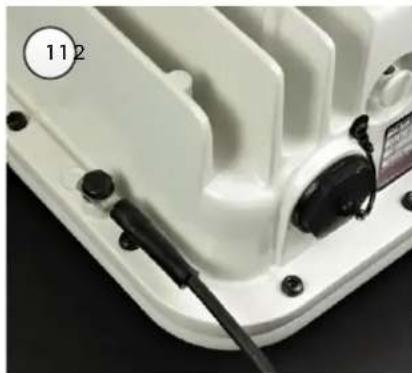
natural_image
Close-up of a white electronic device with black connectors and a labeled component (112), no readable text or symbols beyond the number.
natural_image
Close-up of a white plastic electronic device with mounting holes and a cable inserted (no visible text or symbols)
natural_image
Close-up of a white mechanical device with black adjustment knobs and a circular dial (no visible text or symbols)Mount the ODU on the mast
Select the most appropriate bracket mounting arrangement from the options listed in Mounting bracket options on page 5-5. Refer to individual procedures below for each of the options:
• Tilt Bracket Assembly on page 5-6
• Tilt Bracket Assembly with band clamps on page 5-8
• Heavy Duty Mounting bracket (Integrated) on page 5-8
• Smart Antenna Clamp Set on page 5-9
The mounting procedures can be adapted to attach the Connectorized, Connectorized+Integrated and Integrated ODUs to a suitable horizontal pole, but the adjustment of azimuth angle is necessarily limited compared with an installation on a vertical pole.
Tilt Bracket Assembly
1 Fix the mounting plate of the Tilt Bracket to the back of the ODU using four of the short bolts, ensuring that the arrow in the plate points towards the top of the ODU. Tighten the four bolts to a torque setting of 5.0 Nm (3.7 lb ft) using a 13 mm spanner or socket.
2 Fit the two long bolts through the bracket body so that the bolt heads engage in the slots as shown. Fit two of the short bolts into the side of the bracket body but do not tighten.
3 Thread two of the nuts to the long bolts and tighten against the bracket body using a 13 mm spanner. Fit the bracket strap and thread the remaining nuts onto the long bolts.
4 Fix the assembled bracket body to the pole, adjust the azimuth angle, and tighten the nuts to a torque setting of 10.0 Nm (7.4 lb ft) using a 13 mm spanner, ensuring that the arrow in the body is pointing upwards.
5 Hoist the ODU to the mounting position. Fit the mounting plate to the bracket body by positioning the open-ended slots over the short bolts. Insert the remaining short bolts through the longer curved slots into the threaded holes in the bracket body. Adjust the elevation angle, and tighten the bolts to a torque setting of 5.0 Nm (3.7 lb ft) using a 13 mm spanner or socket.

natural_image
Close-up of a white plastic mechanical component with red circular annotations highlighting features (no text or symbols visible)
natural_image
Close-up of a mechanical component with mounting holes and a central arrow, no visible text or symbols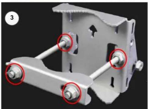
natural_image
3D mechanical assembly with four bolts and mounting holes, no visible text or symbols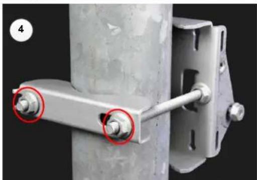
natural_image
Close-up of a metal bracket with two red-circled fasteners inserted, mounted on a cylindrical metal frame (no text or symbols visible)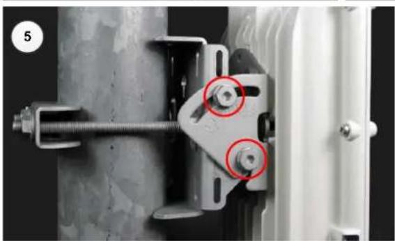
natural_image
Close-up of a mechanical clamp or bracket assembly with two red-circled bolts (no text or symbols visible)Tilt Bracket Assembly with band clamps
1 Follow Step 1 for the Tilt Bracket Assembly procedure above.
2 Feed the band clamps through the slots in the bracket body. Secure the bracket body to the pole using band clamps (not supplied by Cambium), ensuring that the arrow in the body is pointing upwards. Adjust the azimuth angle, and tighten the band clamps to a torque setting of 6.0 Nm (4.5 lb ft).
3 Hoist the ODU to the mounting position. Fix the mounting plate to the bracket body with four of the short bolts, using a 13 mm spanner or socket. Adjust the elevation angle, and tighten the bolts to a torque setting of 5.0 Nm (3.7 lb ft).
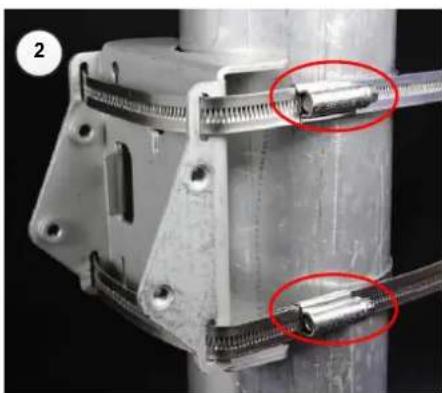
natural_image
Close-up of a mechanical assembly with two red-circled components, no visible text or symbols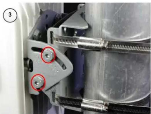
natural_image
Close-up of mechanical components with red circles highlighting two screws (no text or symbols visible)Heavy Duty Mounting bracket (Integrated)
1 Fix the mounting plate to the back of the ODU using the four bolts, and spring and plain washers provided. Ensure that the spring washer is between the bolt head and the plain washer Tighten the bolts to a torque setting of 5.0 Nm (3.7 lb ft).
2 Attach the bracket body to the mounting plate using the M8 bolt, spring and plain washers. Ensure that the spring washer is between the bolt head and the plain washer.
3 Hoist the ODU to the mounting position.
4 Attach the bracket body to the pole using the bracket clamp, M8 bolts, and spring and plain washers. Ensure that the spring washer is between the bolt head and the plain washer.
5 Adjust the elevation and azimuth to achieve visual alignment. Tighten all three bracket bolts to a torque of 8.0 Nm (6.0 lb ft).

natural_image
Close-up of a metallic mechanical component mounted on a white plastic cooling panel (no text or symbols visible)
natural_image
Close-up of a metallic mechanical component mounted on a white grid base, with a red circular annotation highlighting a specific part (no text or symbols visible)
natural_image
Close-up of a mechanical clamp or bracket assembly with two red-circled pins, no visible text or symbolsSmart Antenna Clamp Set
1 Fit two long screws through the inner strap for the top bracket, and secure in position using two nuts. Repeat for the inner strap for the bottom bracket.
2 Attach the top bracket to the ODU using three nuts. Tighten all three nuts to a torque of 4.0 Nm (3.0 lbf ft).
3 Attach the bottom bracket to the ODU using three nuts. Tighten all three nuts to a torque of 4.0 Nm (3.0 lbf ft).
4 Attach the inner strap to the top bracket using two short screws.
5 Attach the inner strap to the bottom bracket using two short screws.
6 Hoist the ODU to the mounting position.
7 Fit the back strap to the top bracket using two nuts. Adjust the azimuth to achieve visual alignment. Tighten the nuts evenly to a torque of 8.0 Nm (5.9 lbf ft).
8 Fit the back strap to the bottom bracket using two nuts. Tighten the nuts evenly to a torque of 8.0 Nm (6.0 lbf ft).
9 Adjust the elevation to achieve visual alignment. Note that the elevation angle is indicated by markings on the top bracket. Tighten two short screws in the upper bracket and two short screws in the bottom bracket to a torque of 6.0 Nm (4.4 lbf ft).

natural_image
Metal mechanical component with two vertical rods and two red-circled holes, no visible text or symbols
natural_image
Metal bracket with three red-circled fasteners on its side (no text or symbols visible)
natural_image
Close-up of a metal bracket with three red-circled screws on its side, no visible text or symbols.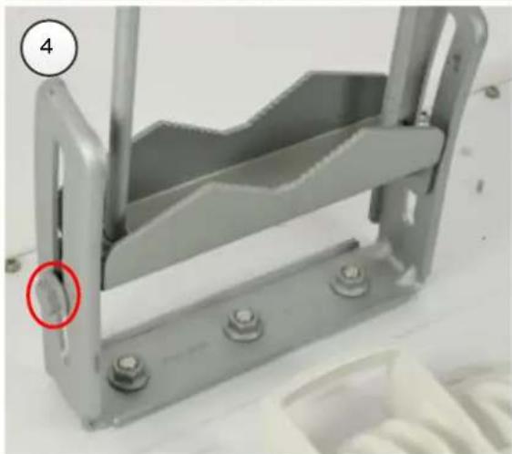
natural_image
Metal mechanical bracket with bolts and a red circle highlighting a small feature (no text or symbols visible)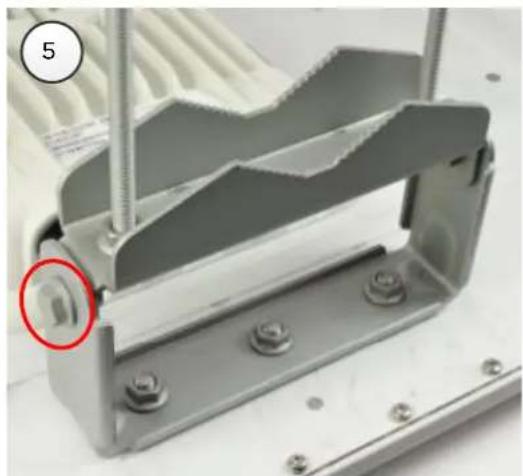
natural_image
Close-up of a metallic mechanical bracket with bolts and a red circle highlighting a small component (no text or symbols visible)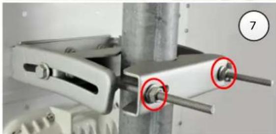
natural_image
Close-up of a mechanical clamp or bracket assembly with two red-circled pins, no visible text or symbols
natural_image
Close-up of a metal clamp securing a cylindrical object with two red-circled fasteners (no text or symbols visible)
natural_image
Close-up of a mechanical clamp or lever mechanism with a red circle highlighting a specific part, mounted on a cylindrical pipe (no visible text or symbols)Mount the top LPU
1 For separate LPU mounting, use the U-bolt bracket from the LPU kit to mount the top LPU on the pole below the ODU. Tighten to a torque setting of 7.0 Nm (5.2 lb ft):
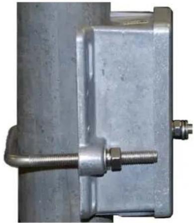
natural_image
Close-up of a metallic mechanical component with threaded fasteners and a U-shaped fitting (no text or symbols visible)Interconnect and ground the ODU and top LPU


Attention Do not attach grounding cables to the ODU mounting bracket bolts, as this arrangement will not provide full protection.
1 Fasten the ODU grounding cable to the top LPU using the M6 (small) lug. Tighten both nuts to a torque of 5 Nm (3.9 lb ft):
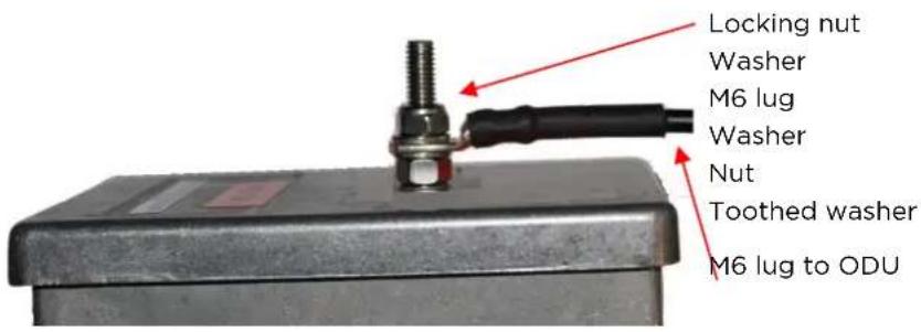
2 Select a tower or building grounding point within 0.3 meters (1 ft) of the ODU bracket. Remove paint from the surface and apply anti-oxidant compound. Fasten the ODU grounding cable to this point using the M10 (large) lug.
3 If local regulations mandate the independent grounding of all devices, add a third ground cable to connect the top LPU directly to the grounding system.
Install external antennas
To mount and connect an external antenna, proceed as follows:
1 Mount the antenna(s) according to manufacturer's instructions. When using separate antennas to achieve spatial diversity, mount one with Horizontal polarization and the other with Vertical polarization.
2 Connect the ODU V and H interfaces to the antenna(s) with RF cable of type LMR-400 (Cambium part numbers 30010194001 and 30010195001) and N type connectors (Cambium part number 09010091001). Tighten the N type connectors to a torque setting of 1.7 Nm (1.3 lb ft).
3 If the ODU is mounted indoors, install lightning arrestors at the building entry point:
4 Form drip loops near the lower ends of the antenna cables. These ensure that water is not channeled towards the connectors.
5 If the ODU is mounted outdoors, weatherproof the N type connectors (when antenna alignment is complete) using PVC tape and self-amalgamating rubber tape.
6 Weatherproof the antenna connectors in the same way (unless the antenna manufacturer specifies a different method).

7 Ground the antenna cables to the supporting structure within 0.3 meters (1 foot) of the ODU and antennas using the Cambium grounding kit (part number 01010419001):

natural_image
Pure electrical circuit lines without any symbols8 Fix the antenna cables to the supporting structure using site approved methods. Ensure that no undue strain is placed on the ODU or antenna connectors. Ensure that the cables do not flap in the wind, as flapping cables are prone to damage and induce unwanted vibrations in the supporting structure.
Install RF Combiners
To install and connect the RF Combiner Kit (N000070L123A) for use in Hot Standby (1+1) and 2+0 protection schemes with shared antennas, proceed as follows:
Assemble and mount the RF Combiners
1 Assemble the RF Combiner Kit according to the instructions provided in the kit, in the wrap-around arrangement, OR
2 Assemble the RF Combiner Kit according to the instructions provided in the kit, in the back-to-back arrangement
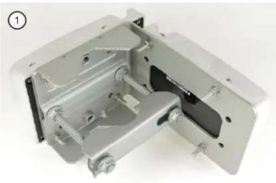
natural_image
Metallic mechanical bracket assembly with mounting holes and bolts (no text or symbols visible)
natural_image
Close-up of a mechanical clamp assembly with white housing and yellow connectors (no text or symbols visible)3, 4, 5 Mount the assembled RF Combiner Kit on the mast or tower standoff. Tighten the fixing nuts to 10 Nm (7.4 lbft) using a 13 mm spanner.

natural_image
Close-up of a mechanical assembly with metallic components and a black cylindrical rod (no visible text or symbols)
natural_image
Close-up of a mechanical device with white housing and yellow connectors, no visible text or symbols
natural_image
Close-up of a white electrical contactor mounted on a black vertical pole with three yellow connectors, no visible text or symbols.Interconnect the RF Combiners, ODUs and antennas
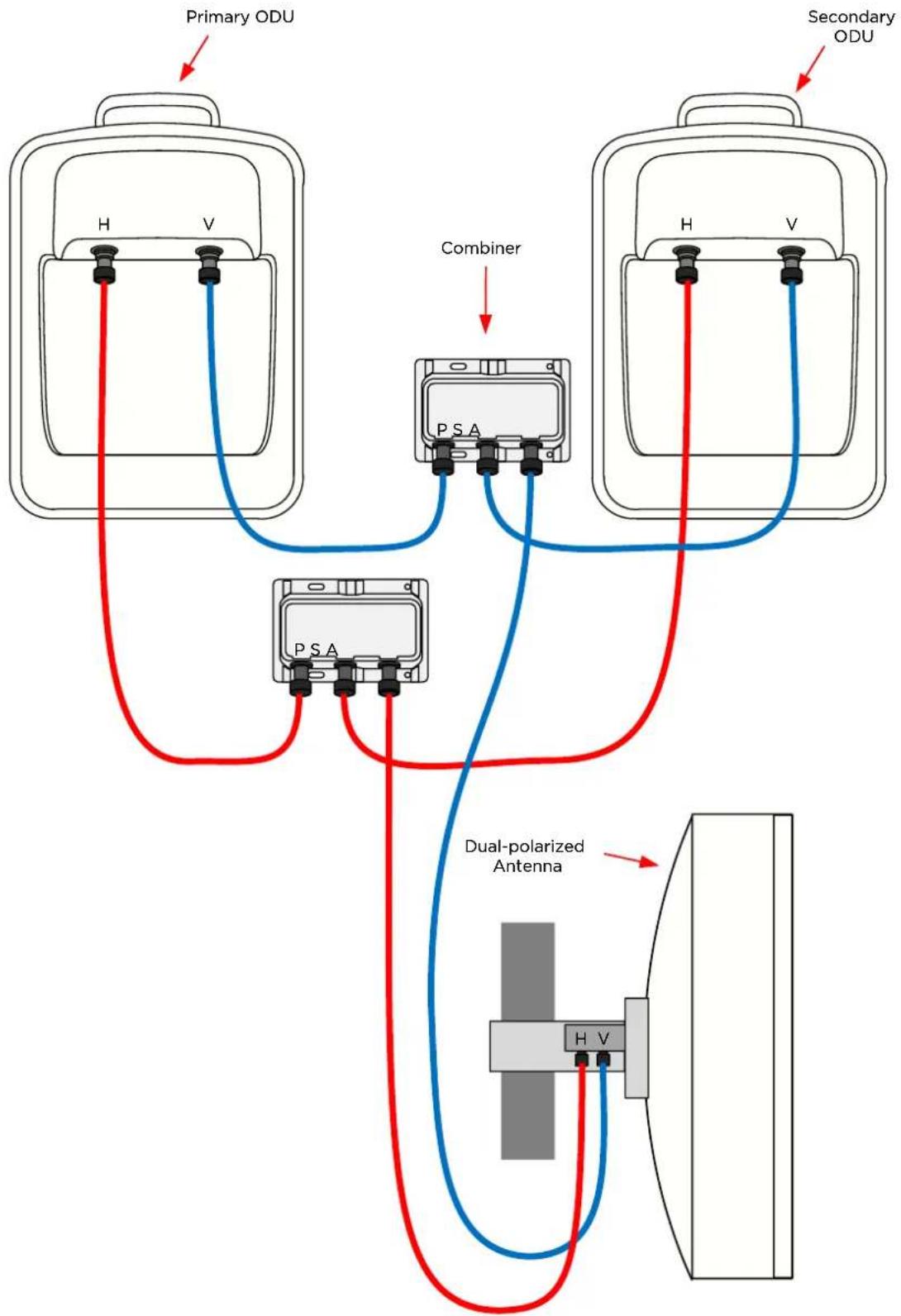
flowchart
graph TD
    A["Primary ODU"] --> B["PSA"]
    C["Secondary ODU"] --> D["PSA"]
    B --> E["Dual-polarized Antenna"]
    D --> E
    B --> F["H V"]
    D --> G["H V"]
    style A fill:#f9f,stroke:#333
    style C fill:#f9f,stroke:#333
    style B fill:#ccf,stroke:#333
    style D fill:#ccf,stroke:#333
    style E fill:#dfd,stroke:#333
    style F fill:#dfd,stroke:#333
Installing the copper Cat5e Ethernet interface
To install the copper Cat5e Ethernet interface, use the following procedures:
• Install the ODU to top LPU drop cable on page 5-19
• Install the main drop cable on page 5-22
• Install the bottom LPU to PSU drop cable on page 5-24
• Test resistance in the drop cable on page 5-26

Attention To avoid damage to the installation, do not connect or disconnect the drop cable when power is applied to the PSU or network terminating equipment.
Attention Do not connect the SFP or Aux drop cables to the PSU, as this may damage equipment.
Attention Always use Cat5e cable that is gel-filled and shielded with copper-plated steel. Alternative types of Cat5e cable are not supported by Cambium Networks. Cambium Networks supply this cable (Cambium part numbers WB3175 and WB3176), RJ45 connectors (Cambium part number WB3177) and a crimp tool (Cambium part number WB3211). The LPU and grounding kit contains a 600 mm length of this cable.
Install the ODU to top LPU drop cable
Use the following cables to connect the PTP 78700 ODU to the top LPU:
| Cambium description | Cambium part number |
| PTP 700 Drop Cable 38999 to 1 x RJ45 male extension Cable 2' | N000070L018A |
| PTP 700 Drop Cable 38999 to 2 x RJ45 male extension Cable 2' | N000070L019A |
For other ODU types, use the 600 mm drop cable supplied in the LPU and Grounding Kit.
Fit glands to the ODU to top LPU drop cable
Fit EMC strain relief cable glands (with black caps) to both ends of the 600 mm length of pre-terminated cable. These parts are supplied in the LPU and grounding kit.
1 Disassemble the gland and thread each part onto the cable (the rubber bung is split). Assemble the spring clip and the rubber bung:

natural_image
Exploded view of a cable showing internal components like connectors, coils, and connectors (no text or symbols visible)
Note Ensure that the four spring fingers fit inside the silver ring.
2 Fit the parts into the body and lightly screw on the gland nut (do not tighten it):
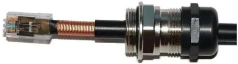
natural_image
Close-up of a black cable connector with metallic fittings and exposed internal wiring (no text or symbols visible)Connect the drop cable to the ODU (PSU port) and LPU
1 For PTP 700 7125-8500 MHz, connect the ODU cable to Connector J1 at the ODU. Ensure that the coupling nut is tightened so that the red ring on the receptacle is no longer visible.
Correct

natural_image
Close-up of a mechanical component with blue and black parts, no visible text or symbolsIncorrect

natural_image
Close-up of a black mechanical component with blue and white markings, mounted on a white surface (no visible text or symbols)2 For other ODU types, (a) Plug the RJ45 connector into the socket in the unit, ensuring that it snaps home. (b) Fit the gland body to the RJ45 port and tighten it to a torque of 5.5 Nm (4.1 lb ft):
(a)

natural_image
Close-up of a hand holding a coiled copper wire connector inserted into a white plastic housing (no text or symbols visible)(b)

natural_image
Close-up of a metallic threaded connector with black and white plastic components, no visible text or symbols3 (a) Plug the RJ45 connector into the socket in the LPU, ensuring that it snaps home.
(b) Fit the gland body to the RJ45 port using a 24 mm spanner, and tighten it to a torque of 5.5 Nm (4.1 lb ft):
(a)

natural_image
Close-up of a metallic mechanical component with a copper-colored connector inserted into a housing (no visible text or symbols)(b)

natural_image
Close-up of a metallic mechanical component with a black connector and red arrow indicating a adjustment or movement (no text or symbols visible)4 (a) Tighten the gland nut at the ODU and LPU until the rubber seal closes on the cable. (b) Do not over-tighten the gland nut, as there is a risk of damage to its internal components:
(a)

natural_image
Close-up of a mechanical component with a black connector and red arrow indicating rotation (no text or symbols visible)(b)
Correct

natural_image
Close-up of a mechanical component with black and metallic surfaces (no visible text or symbols)Incorrect
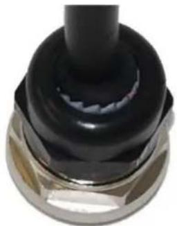
natural_image
Close-up of a black mechanical component with a cylindrical shaft and flange (no visible text or symbols)Disconnect the drop cable from the LPU or ODU
Use this procedure if it is necessary to remove an EMC strain relief cable gland and RJ45 connector from the ODU (as illustrated) or LPU.
1 (a) Remove the gland nut. Wiggle the drop cable to release the tension of the gland body. When the tension in the gland body is released, a gap opens at the point show. Unscrew the gland body. (b) Use a small screwdriver to press the RJ45 locking tab, then remove the RJ45 connector.
(a)

(b)

natural_image
Close-up of a hand using a screwdriver to insert a small component into a white plastic housing (no text or symbols visible)Install the main drop cable

Warning The metal screen of the drop cable is very sharp and may cause personal injury.
- ALWAYS wear cut-resistant gloves (check the label to ensure they are cut resistant).
• ALWAYS wear protective eyewear.
• ALWAYS use a rotary blade tool to strip the cable (DO NOT use a bladed knife).

Warning Failure to obey the following precautions may result in injury or death:
- Use the proper hoisting grip for the cable being installed. If the wrong hoisting grip is used, slippage or insufficient gripping strength will result.
- Do not reuse hoisting grips. Used grips may have lost elasticity, stretched, or become weakened. Reusing a grip can cause the cable to slip, break, or fall.
• The minimum requirement is one hoisting grip for each 60 m (200 ft) of cable.
Cut to length and fit hoisting grips
1 Cut the main drop cable to length from the top LPU to the bottom LPU.
2 Slide one or more hoisting grips onto the top end of the drop cable.
3 Secure the hoisting grip to the cable using a special tool, as recommended by the manufacturer.
Terminate with RJ45 connectors and glands

Attention Check that the crimp tool matches the RJ45 connector, otherwise the cable or connector may be damaged.
1 Strip the cable outer and inner sheath, and fit the RJ45 connector load bar. Fit the RJ45 connector housing as shown. To ensure there is effective strain relief, locate the cable inner sheath under the connector housing tang.
The color code for the Superior Essex cable is shown here.
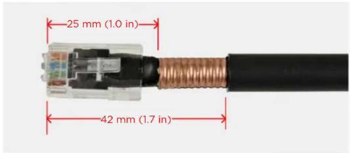
Color Code
| Contact | Color |
| 1 | Light Orange |
| 2 | Orange |
| 3 | Light Green |
| 4 | Blue |
| 5 | Light Blue |
| 6 | Green |
| 7 | Light Brown |
| 8 | Brown |
2 Fit the gland components in the order shown in Fit glands to the ODU to top LPU drop cable on page 5-19, but do not tighten the gland nut.
Hoist and fix the main drop cable

Warning Failure to obey the following precautions may result in injury or death:
- Use the hoisting grip to hoist one cable only. Attempting to hoist more than one cable may cause the hoisting grip to break or the cables to fall.
- Do not use the hoisting grip for lowering cable unless the clamp is securely in place.
- Maintain tension on the hoisting grip during hoisting. Loss of tension can cause dangerous movement of the cable and result in injury or death to personnel.
- Do not release tension on the grip until after the grip handle has been fastened to the supporting structure.
- Do not apply any strain to the RJ45 connectors.

Attention Do not lay the drop cable alongside a lightning air terminal.
1 Hoist the top end of the main drop cable up to the top LPU, following the hoist manufacturer's instructions. When the cable is in position, fasten the grip handle to the supporting structure and remove the hoist line.
2 Connect the main drop cable to the top LPU by following the procedure Connect the drop cable to the ODU (PSU port) and LPU on page 5-20.
3 Run the main drop cable to the site of the bottom LPU.
4 Attach the main drop cable to the supporting structure using site approved methods.
Ground the main drop cable
At all required grounding points, connect the screen of the main drop cable to the metal of the supporting structure using the cable grounding kit (Cambium part number 01010419001).
Install the bottom LPU to PSU drop cable
Install the bottom LPU
Install the bottom LPU, ground it, and connect it to the main drop cable.
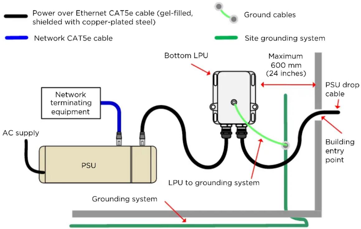
flowchart
graph TD
    A["Power over Ethernet CAT5e cable (gel-filled, shielded with copper-plated steel)"] --> B["Network CAT5e cable"]
    B --> C["Network terminating equipment"]
    C --> D["AC supply"]
    D --> E["PSU"]
    E --> F["LPU to grounding system"]
    F --> G["Building entry point"]
    G --> H["PSU drop cable"]
    H --> I["Maximum 600 mm (24 inches)"]
    I --> J["Bottom LPU"]
    J --> K["Ground cables"]
    style A fill:#f9f,stroke:#333
    style B fill:#bbf,stroke:#333
    style C fill:#bfb,stroke:#333
    style D fill:#ffb,stroke:#333
    style E fill:#fbb,stroke:#333
    style F fill:#fff,stroke:#333
    style G fill:#fff,stroke:#333
    style H fill:#fff,stroke:#333
    style I fill:#fff,stroke:#333
    style J fill:#fff,stroke:#333
    style K fill:#fff,stroke:#333
1 Select a mounting point for the bottom LPU within 600 mm (24 in) of the building entry point. Mount the LPU vertically with cable glands facing downwards
2 Connect the main drop cable to the bottom LPU by following the procedure Connect the drop cable to the ODU (PSU port) and LPU on page 5-20.
3 Fasten one ground cable to the bottom LPU using the M6 (small) lug. Tighten both nuts to a torque of 5 Nm (3.9 lb ft):

natural_image
Close-up of a metallic electrical component with a screw and cable, no visible text or symbolsLocking nut
Washer
M6 lug
Washer
Nut
Toothed washer
M10 lug to ground
4 Select a building grounding point near the LPU bracket. Remove paint from the surface and apply anti-oxidant compound. Fasten the LPU ground cable using the M10 (large) lug.
Install the LPU to PSU drop cable
Use this procedure to terminate the bottom LPU to PSU drop cable with RJ45 connectors at both ends, and with a cable gland at the LPU end.

Warning The metal screen of the drop cable is very sharp and may cause personal injury. ALWAYS wear cut-resistant gloves (check the label to ensure they are cut resistant). ALWAYS wear protective eyewear. ALWAYS use a rotary blade tool to strip the cable, not a bladed knife.

Attention Check that the crimp tool matches the RJ45 connector, otherwise the cable or connector may be damaged.
1 Cut the drop cable to the length required from bottom LPU to PSU.
2 At the LPU end only:
- Fit one cable gland and one RJ45 connector by following the procedure Terminate with RJ45 connectors and glands on page 5-23.
- Connect this cable and gland to the bottom LPU by following the procedure Connect the drop cable to the ODU (PSU port) and LPU on page 5-20.
3 At the PSU end only: Do not fit a cable gland. Strip the cable outer sheath and fit the RJ45 connector load bar. Fit the RJ45 connector housing. To ensure there is effective strain relief, locate the cable inner sheath under the connector housing tang:

Test resistance in the drop cable
Connect the bottom end of the copper Cat5e drop cable to a suitable drop cable tester and test that the resistances between pins are within the correct limits, as specified in the table below. If any of the tests fail, examine the drop cable for wiring faults.
| Measure the resistance between... | Enter measured resistance | To pass test, resistance must be... | Circle “Pass” or “Fail” | Additional tests and notes |
| Pins 1 and 2 | Ohms | <20 Ohms (60 Ohms) (*1) | Pass Fail | Resistances must be within 10% of each other (*2). Circle “Pass” or “Fail”: Pass Fail |
| Pins 3 and 6 | Ohms | <20 Ohms (60 Ohms) (*1) | Pass Fail | |
| Pins 4 and 5 | Ohms | <20 Ohms (60 Ohms) (*1) | Pass Fail | |
| Pins 7 and 8 | Ohms | <20 Ohms (60 Ohms) (*1) | Pass Fail | |
| Pin 1 and screen (ODU ground) | K Ohms | >100K Ohms | Pass Fail | These limits apply regardless of cable length. |
| Pin 8 and screen (ODU ground) | K Ohms | >100K Ohms | Pass Fail |
(*1) A resistance of 20 Ohms is the maximum allowed when the cable is carrying Ethernet.
A resistance of 60 Ohms is the maximum allowed when the cable is carrying only power to the ODU (when Ethernet is carried by one of the other ODU interfaces).
(*2) Ensure that these resistances are within 10% of each other by multiplying the lowest resistance by 1.1 - if any of the other resistances are greater than this, the test has failed.
Installing the PSU
Install the AC+DC Enhanced Power Injector 56V (Cambium part number C000065L002C or C000065L002D). Refer to Installing the AC+DC Enhanced Power Injector 56V on page 5-27.

Warning Always use an appropriately rated and approved AC supply cord-set in accordance with the regulations of the country of use.
Attention As the PSU is not waterproof, locate it away from sources of moisture, either in the equipment building or in a ventilated moisture-proof enclosure. Do not locate the PSU in a position where it may exceed its temperature rating.
Attention Do not plug any device other than a PTP 700 ODU into the ODU port of the PSU. Other devices may be damaged due to the non-standard techniques employed to inject DC power into the Ethernet connection between the PSU and the ODU.
Do not plug any device other than a Cambium PTP 700 PSU into the PSU port of the ODU. Plugging any other device into the PSU port of the ODU may damage the ODU and device.
Installing the AC+DC Enhanced Power Injector 56V
Follow this procedure to install the AC+DC Enhanced Power Injector 56V (Cambium part number C000065L002C or C000065L002D):
1 Mount the AC+DC Power Injector 56V by screwing it to a vertical or horizontal surface using the four screw holes (two holes circled):
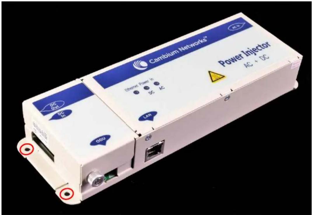
2 Form a drip loop on the PSU end of the LPU to PSU drop cable. The drip loop ensures that any moisture that runs down the cable into the cabinet or enclosure cannot enter the PSU.
3 (a) Undo the retaining screw, hinge back the cover and plug the drop cable or the cable from the PTP-SYNC into the port. (b) Close the cover and secure with the screw. (c) When the system is ready for network connection, connect the network Cat5e cable to the LAN port of the PSU:
Installing a PTP-SYNC unit
To install a PTP-SYNC unit (for TDD synchronization), use the following procedures:
• Mounting the PTP-SYNC unit on page 5-29
• Connecting up the PTP-SYNC unit on page 5-30
• Powering up the PTP-SYNC installation on page 5-32

Attention The PTP-SYNC unit must be installed indoors in a non-condensing environment, otherwise it will be prone to water damage.
Attention To protect the PTP-SYNC from damage, disconnect the power supply from the PSU before connecting up the PTP-SYNC.
Mounting the PTP-SYNC unit
Use this procedure to install the PTP-SYNC unit in the equipment building, either in a rack or on a wall.
- Racking mounting option: fix the PTP-SYNC to the rack mount using the M3 screws from the rack mount installation kit (Figure 110).
- Wall mounting option: mount the PTP-SYNC vertically with interfaces and cabling facing downwards (Figure 111).
Figure 110 PTP-SYNC mounted in a rack

Figure 111 PTP-SYNC mounted on a wall

natural_image
Black rectangular electronic device with multiple black connectors and wires, no visible text or symbolsConnecting up the PTP-SYNC unit
Use this procedure to connect the PTP-SYNC to the AC+DC Power Injector 56V, ODU, GPS receiver (if fitted), and LPU (if fitted).
1 Disconnect the power supply from the AC+DC Power Injector 56V.
2 If using GPS, connect the cable from the GPS unit to the GPS/SYNC IN port.

3 To link clustered PTP-SYNC units, connect the SYNC OUT port of the first PTP-SYNC to the GPS/SYNC IN port of the second PTP-SYNC in the chain. Repeat for subsequent PTP-SYNC units in the chain.

natural_image
Two black network switches with Ethernet ports and black cables, no visible text or symbols4 Connect the cable from the PSU to the PIDU IN port. A suitable 1 meter cable is included in the PTP-SYNC kit.

5 Connect the cable from the ODU to the ODU OUT port.

6 Use a grounding cable to connect the ground stud of the PTP-SYNC to the master ground bar of the building, or to the rack ground bar.
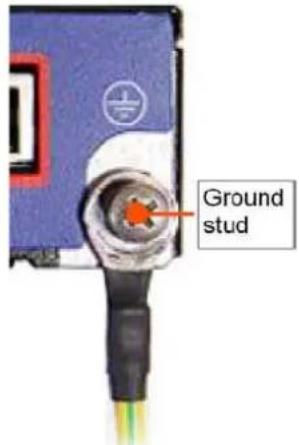
Powering up the PTP-SYNC installation
Use this procedure to power up the PTP-SYNC installation.

Attention Ensure that all cables are connected to the correct interfaces of the PTP SYNC unit and the GPS receiver (if used). Ensure that the installation is correctly grounded. Failure to do so may result in damage to the equipment.
1 Connect the power supply to the PSU.
2 Within 90 seconds, the PTP-SYNC STATUS LED should blink once every second to show that satellite lock has been achieved.
3 If the system does not operate correctly, refer to Testing PTP-SYNC on page 8-15.
Installing the Trimble Accutime GPS receiver
To install a GPS receiver as the timing reference source for PTP-SYNC, use the following procedures:
• Mounting the GPS receiver on page 5-33
• Preparing the GPS drop cable on page 5-33
• Assembling an RJ45 plug and housing for GPS on page 5-34
• Assembling a 12 way circular connector on page 5-36
• Connecting the GPS drop cable on page 5-40
• Top grounding point for GPS adapter cable on page 5-40
• Installing and connecting the GPS LPU on page 5-42

Attention A Prior to power-up of equipment, ensure that all cables are connected to the correct interfaces of the PTP-SYNC unit and the GPS receiver module. Failure to do so may result in damage to the equipment.
Mounting the GPS receiver
Mount the GPS receiver (following manufacturer's instructions) upon either an external wall (Figure 50) or a metal tower or mast (Figure 51).
Preparing the GPS drop cable
Use this procedure to make the main drop cable that will connect the GPS receiver to its bottom LPU. GPS drop cables do not require top LPUs.

Attention Always use Cat5e cable that is gel-filled and shielded with copper-plated steel. Alternative types of cable are not supported by Cambium.
1 Measure the distance from the GPS receiver to the LPU site at building entry.
2 Cut the required length of drop cable.
3 Attach one or more hoisting grips to the top end of the cable, as described in Install the main drop cable on page 5-22.
4 Fit a suitable GPS connector to the top end of the drop cable:
- If a GPS adapter cable kit is available, attach the plug housing and an RJ45 plug to the top end of the main GPS drop cable, as described in Assembling an RJ45 plug and housing for GPS on page 5-34.
- If a GPS adapter cable kit is not available, fit a 12 way circular connector to the top end of the main drop cable as described in Assembling a 12 way circular connector on page 5-36.
5 Hoist the GPS drop cable safely up a tower or building, as described in Install the main drop cable. on page 5-22.
Assembling an RJ45 plug and housing for GPS
Use this procedure to assemble the plug housing over the end of the drop cable. This procedure is only performed when a GPS adapter cable kit is available. This kit is used to connect the Trimble Acutime™ GG GPS receiver or the Trimble Acutime™ Gold GPS receiver to the GPS drop cable.
The kit contains an adapter cable (GPS receiver circular connector to RJ45 socket) and an RJ45 plug housing. The plug housing should be assembled over the end of the drop cable to provide a sealed connection to the adapter cable.

Note These instructions are for the preparation of the Cambium-supplied drop cable type (Superior Essex EnduraGain OSP Armored Cat 5e). Other types of cable may need different preparation methods.
1 Prepare the top end of the GPS drop cable.
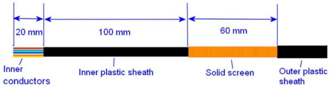
2 Install plug housing from the converter kit onto the prepared cable. Do not tighten the nuts at this stage.

3 Install the RJ45 crimp plug.
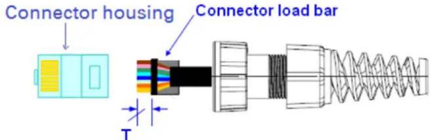
Start with tails over-length to assist insertion into load bar, then trim them to 5 mm (T). Connect the RJ45 pins to the following conductors (Superior Essex EnduraGain OSP Armored Cat 5e colors):

4 Assemble plug housing:
Depress the RJ45 locking tab (A).
Slide the plug housing assembly (B) over the RJ45 plug.
Tighten the sealing nut (C). This is easier to fully tighten when the plug housing is mated to the socket of the adapter cable.

5 Check the assembly. This is an example of an assembled plug housing on the end of a drop cable:

natural_image
Close-up of a black and copper wire cable with a metallic connector (no text or symbols visible)Assembling a 12 way circular connector
Use this procedure to connect the GPS drop cable to a 12 way circular connector. This procedure is only performed when a GPS adapter cable kit is NOT available.


Note This procedure requires a soldering iron and solder.
Attention The drop cable has solid copper conductors. There are a limited number of times each conductor can be bent before it fatigues and fails.
Table 163 shows how the 12 way circular connector locations map to the PTP-SYNC RJ45 pins.
Figure 112 illustrates this mapping.
Table 163 GPS 12 way circular connector to RJ45 pin mappings
| GPS connector location | Function | Cat5e wire color | PTP-SYNC (J10) RJ45 pin | PTP-SYNC signal name | |
| Conventional | Supported drop cable | ||||
| 1 | DC Pwr (12V) | Orange/White | Light Orange | 1 | 12VGPS |
| 2 | RxB- | Brown/White | Light Brown | 7 | GPS_TXDA |
| 3 | RxB+ | Brown | Brown | 8 | GPS_TXDB |
| 4 | TxB- | Blue | Blue | 4 | GPS_RXDA |
| 5 | TxB+ | Blue/White | Light Blue | 5 | GPS_RXDB |
| 6 | RxA- | N.C | N.C | --- | |
| 7 | RxA+ | N.C | N.C | --- | |
| 8 | TxA- | N.C | N.C | --- | |
| 9 | DC Ground | Orange | Orange | 2 | GND |
| 10 | TxA+ | N.C | N.C | --- | |
| 11 | Tx1PPS+ | Green/White | Light Green | 3 | GPS_1PPSA |
| 12 | Tx1PPS- | Green | Green | 6 | GPS_1PPSB |
Figure 112 Inserting RJ45 pins into the 12 way circular connector

1 Prepare the drop cable end as follows:
- Bare back the cable outer and copper screen to 50mm.
- Bare back the cable inner to 17mm.
- Un-twist the cable pairs.
- Strip the individual conductors to 5mm.

natural_image
Close-up of a black cable with visible internal wires, placed above a metal ruler for scale (no text or symbols on the cable itself)2 Fit the plug outer, associated boot, and boot insert.

natural_image
Close-up of a black cable with exposed internal wires and connectors (no text or symbols visible)3 Connect the socket contacts using either of the following techniques:
- Crimp: Crimp the socket contacts onto each of the conductors using the correct crimp tool and positioner, setting the wire size selector to "3" for 24AWG wire.

natural_image
Close-up of a green DMC tool with exposed wires and connectors, no visible text or symbols on the main subject.- Solder: When soldering the socket contacts onto each of the conductors, ensure that there is no solder or flux residue on the outside of the contact. Care should also be taken that the individual conductor insulation does not peel back with the soldering heat, allowing possible shorts when assembled into the plug shell.
4 Fit four dummy contacts into the unused 12 way circular connector locations (6, 7, 8 and 10), to provide strength and sealing. Push the contacts in from the pin insertion side.
Pin insertion side:
Plug mating side:

natural_image
Close-up of a black circular electronic component with multiple pins and mounting holes (no visible text or symbols)
natural_image
Close-up of a black circular electrical connector with four gold pins (no text or symbols visible)5 Insert the eight RJ45 contact pins into the pin insertion side of the 12 way circular connector in accordance with Figure 112.
It is easiest to insert the pins from the center out, in descending order of Trimble location number, that is, 12, 11, 9, 5, 4, 3, 2, 1. Push the contacts in so that the shoulder on the contact fits into the hole in the plug shell. When all contacts have been fitted, push them in further to engage with the locking mechanism in the plug shell. This can be done by applying pressure to the contact with a small diameter stiff object, such as tweezers.

Note If a contact is pushed in to the point where the locking mechanism engages before all of the contacts have been inserted it will limit the amount of room available to fit the remaining contacts, requiring harder bends to be applied.

natural_image
Close-up of a black cable with exposed wires and connectors (no text or symbols visible)6 Fit the plug to its shell. The plastic ring fits inside the rubber boot and ensures a tight fit when the plug body is clipped onto the plug shell. Be aware that the plug body is a hard push fit onto the plug shell.

natural_image
Close-up of a black electrical connector with exposed wires and connectors (no text or symbols visible)7 Fit the strain relief clip.

natural_image
Close-up of a black electrical connector with metal fittings and connectors (no visible text or symbols)Connecting the GPS drop cable
Use this procedure to connect the GPS drop cable to the GPS unit and supporting structure.
1 If a GPS adapter cable is available, use it to connect the main GPS drop cable to the GPS unit:

natural_image
Close-up of a white electrical plug with black cable and red wire, isolated on plain background (no text or symbols)2 If a GPS adapter cable is not available, connect the main GPS drop cable to the GPS unit via a 12 way circular connector. Weatherproof the connection as follows:
- Wrap a layer of self-amalgamating tape, starting 25mm below the bared back outer of the cable and finishing at the GPS housing.
- Wrap a layer of PVC tape, starting just below the start of the self-amalgamating tape and finishing at the GPS housing, overlapping at half width.
- Repeat with four more layers of PVC tape alternating the start and finish ends.

natural_image
Close-up of a white bulb with a black cable inserted, no visible text or symbols3 Lay the main drop cable as far as the building entry point, ensuring there is enough length to extend through the wall of the building to the LPU.
4 Attach the main GPS drop cable to the supporting structure using site approved methods.
5 Ground the GPS drop cable to the supporting structure at the points shown in Figure 50 (wall installation) or Figure 51 (mast or tower installation):
- For standard grounding instructions, see Creating a drop cable grounding point on page 5-54.
- If a GPS adapter cable has been installed, see Top grounding point for GPS adapter cable on page 5-40.
Top grounding point for GPS adapter cable
If a GPS adapter cable has been installed (Figure 113), use this procedure to ground the drop cable at the point where the solid screen is already exposed, and weatherproof both the ground cable joint and the RJ45 connection.
Figure 113 Grounding and weatherproofing requirements for GPS adapter cable

Follow the procedure described in Creating a drop cable grounding point on page 5-54, but observe the following differences:
- There is no need to remove 60mm (2.5inches) of the drop cable outer sheath, as this has already been done.
- Wrap the top layer of self-amalgamating tape around the complete assembly (not just the ground cable joint), including the RJ45 connection with the GPS adapter cable (Figure 114).
- Wrap all five layers of PVC tape around the complete assembly (Figure 115). Wrap the layers in alternate directions: (1st) bottom to top; (2nd) top to bottom; (3rd) bottom to top; (4th) top to bottom; (5th) bottom to top. The edges of each layer should be 25mm (1 inch) above (A) and 25 mm (1 inch) below (B) the previous layer.
- Check that the joint between the GPS adapter cable, drop cable and ground cable is fully weatherproofed (Figure 116).
Figure 114 Wrapping self-amalgamating tape around the GPS adapter cable joint

Figure 115 Wrapping PVC tape around the GPS adapter cable joint

Figure 116 Grounding and weatherproofing example for GPS adapter cable

natural_image
Close-up of a black, flexible wire with a white spherical object attached at the top (no text or symbols visible)Installing and connecting the GPS LPU
Install and ground the GPS drop cable LPU at the building (or cabinet) entry point, and install the LPU-PTP-SYNC drop cable, as described in Install the bottom LPU on page 5-24.
Connect this cable to the PTP-SYNC unit as described in Connecting up the PTP-SYNC unit on page 5-30.
Installing an SFP Ethernet interface
In more advanced configurations, there may be an optical or copper Cat5e Ethernet interface connected to the SFP port of the ODU. Refer to Typical deployment on page 3-2 for diagrams of these configurations.
Adapt the installation procedures in this chapter as appropriate for SFP interfaces, noting the following differences from a PSU interface:
- Install an optical or copper SFP module in the ODU (SFP port) and connect the SFP optical or copper cable into this module using the long cable gland from the SFP module kit. This is described in the following procedures:
• Fitting the long cable gland on page 5-45 - Inserting the SFP module on page 5-46
• Connecting the cable on page 5-48
• Fitting the gland on page 5-49 - Removing the cable and SFP module on page 5-51
- Optical cables do not require LPUs or ground cables.
- At the remote end of an SFP drop cable, use an appropriate termination for the connected device.
- If the connected device is outdoors, not in the equipment building or cabinet, adapt the grounding instructions as appropriate.
- PTP 700 LPUs are not suitable for installation on SFP copper Cat5e interfaces. For SFP drop cables, obtain suitable surge protectors from a specialist supplier.
• Ground the top LPUs and surge protector to the same point on the ODU (Figure 117).
Figure 117 ODU with copper Cat5e connections to all three Ethernet ports
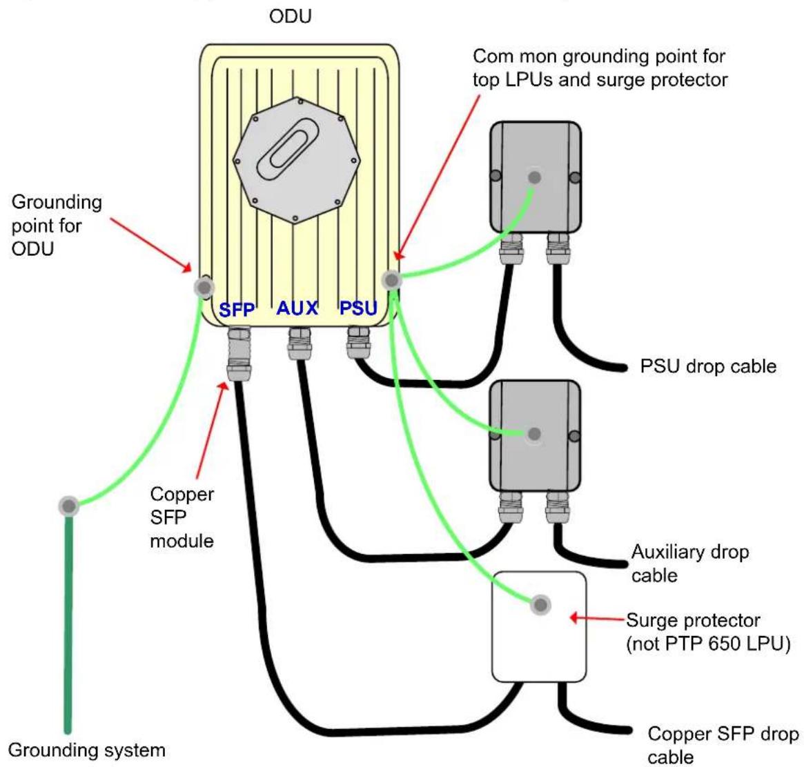
Fitting the long cable gland
Optical SFP interface: Disassemble the long cable gland and thread its components over the LC connector at the ODU end as shown below.
Copper Cat5e SFP interface: Disassemble the long cable gland and thread its components over the RJ45 connector at the ODU end as shown below.
1 Disassemble the gland:

natural_image
Exploded view of a metallic cylindrical connector showing internal components and assembly (no text or symbols visible)2 Thread each part onto the cable (the rubber bung is split):

3 Assemble the spring clip and the rubber bung (the clips go inside the ring):
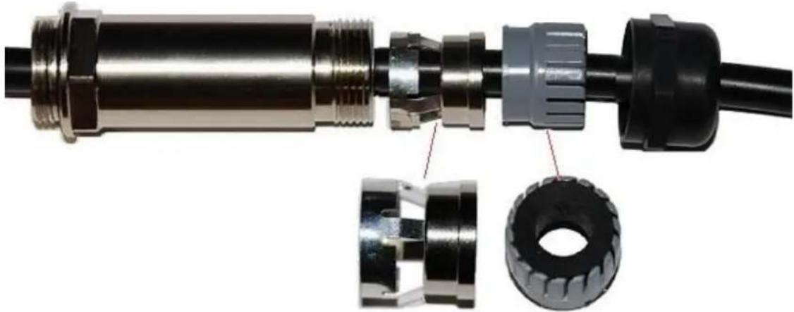
natural_image
Close-up of a mechanical connector with internal parts, showing metallic fittings and a tire (no text or symbols visible)4 Fit the parts into the body and lightly screw on the gland nut (do not tighten it):
Optical

natural_image
Close-up of a metallic cylindrical electronic component with blue and orange wires, no visible text or symbolsCopper

natural_image
Close-up of a metallic cylindrical electronic component with a coiled cable and connector (no visible text or symbols)Inserting the SFP module
To insert the SFP module into the ODU, proceed as follows:
1 Remove the blanking plug from the SFP port of the ODU:

natural_image
Close-up of a hand inserting a coin into a white electronic device housing (no visible text or symbols)2 Insert the SFP module into the SFP receptacle with the label up:
Optical

Copper

3 Push the module home until it clicks into place:
Optical
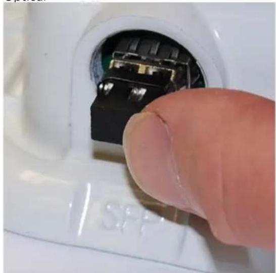
natural_image
Close-up of a finger inserting a small electronic component into a white plastic housing (no visible text or symbols)Copper

natural_image
Close-up of a hand inserting a small electronic component into a white plastic housing (no text or symbols visible)4 Rotate the latch to the locked position:
Optical

Copper

Connecting the cable

Attention The fiber optic cable assembly is very delicate. To avoid damage, handle it with extreme care. Ensure that the fiber optic cable does not twist during assembly, especially when fitting and tightening the weatherproofing gland.
Do not insert the power over Ethernet drop cable from the PSU into the SFP module, as this will damage the module.
1 Remove the LC connector dust caps from the ODU end (optical cable only):
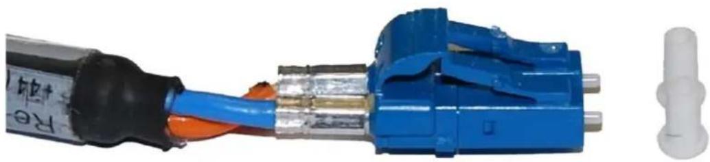
natural_image
Close-up of a blue electrical connector with black and orange wires, alongside a white plastic component (no text or symbols visible)2 Plug the connector into the SFP module, ensuring that it snaps home:
Optical

natural_image
Close-up of hands inserting a blue B2B connector into a white electrical socket (no text or symbols visible)Copper

natural_image
Close-up of a hand holding a wire with copper insulation, inserted into a small electronic component (no visible text or symbols)Fitting the gland
1 Fit the gland body to the SFP port and tighten it to a torque of 5.5 Nm (4.3 lb ft)

natural_image
Close-up of a metallic mechanical component with threaded shaft and black base, no visible text or symbols2 Fit the gland nut and tighten until the rubber seal closes on the cable. Do not over-tighten the gland nut, as there is a risk of damage to its internal components:

natural_image
Close-up of a hand holding a metallic cylindrical connector with black and white base (no text or symbols visible)
Removing the cable and SFP module
Do not attempt to remove the module without disconnecting the cable, otherwise the locking mechanism in the ODU will be damaged.
1 Remove the cable connector by pressing its release tab before pulling it out:
Optical

Copper

2 Rotate the latch to the unlocked position. Extract the module by using a screwdriver:
Optical
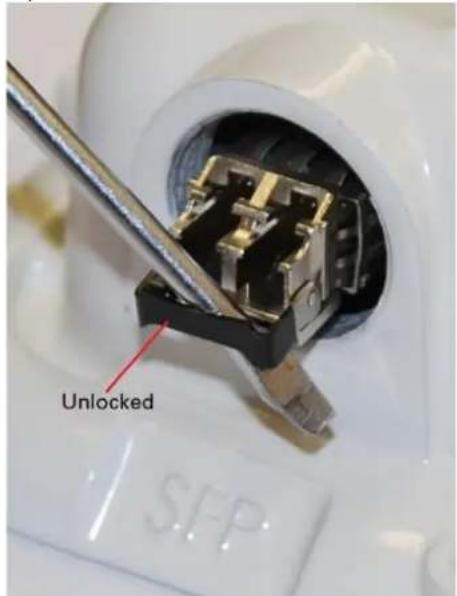
Copper

Installing an Aux Ethernet interface
In more advanced configurations, there may be a copper Cat5e Ethernet interface connected to the Aux port of the ODU. Refer to Typical deployment on page 3-2 for a diagram of this configuration.
Adapt the installation procedures in this chapter as appropriate for the Aux interface, noting the following differences:
- At the remote end of the Aux drop cable, use an appropriate termination for the connected device (for example, a video camera or wireless access point).
- If the connected device is outdoors, not in the equipment building or cabinet, adapt the grounding instructions as appropriate.
• Ground the top LPUs and surge protector to the same point on the ODU (Figure 117).
Supplemental installation information
This section contains detailed installation procedures that are not included in the above topics, such as how to strip cables, create grounding points and weatherproof connectors.
Stripping drop cable
When preparing drop cable for connection to the PTP 700 ODU or LPU, use the following measurements:

When preparing drop cable for connection to the PTP 700 PSU (without a cable gland), use the following measurements:

Trim to 5 mm (start with tails over-length to assist insertion into load bar)
Creating a drop cable grounding point
Use this procedure to connect the screen of the main drop cable to the metal of the supporting structure using the cable grounding kit (Cambium part number 01010419001).
To identify suitable grounding points, refer to Drop cable grounding points on page 3-15.
1 Remove 60 mm (2.5 inches) of the drop cable outer sheath.

natural_image
Close-up of a black cable with copper wire wrapped around its end, placed next to a ruler for scale (no text or symbols visible on the cable itself)2 Cut 38mm (1.5 inches) of rubber tape (self-amalgamating) and fit to the ground cable lug. Wrap the tape completely around the lug and cable.

natural_image
Close-up of a copper-colored electrical terminal with two orange leads and a black cable, no text or symbols visible.3 Fold the ground wire strap around the drop cable screen and fit cable ties.

natural_image
Close-up of a black electrical cable with copper and metal components, no visible text or symbols4 Tighten the cable ties with pliers. Cut the surplus from the cable ties.

natural_image
Close-up of metal pliers and copper wire tools on a textured surface (no text or symbols visible)5 Cut a 38mm (1.5 inches) section of self-amalgamating tape and wrap it completely around the joint between the drop and ground cables.

natural_image
Close-up of a black electrical plug with exposed wires and insulation (no text or symbols visible)6 Use the remainder of the self-amalgamating tape to wrap the complete assembly. Press the tape edges together so that there are no gaps.

natural_image
Close-up of a black cable with exposed insulation and twisted ends, no text or symbols visible7 Wrap a layer of PVC tape from bottom to top, starting from 25 mm (1 inch) below and finishing 25 mm (1 inch) above the edge of the self-amalgamating tape, over lapping at half width.

natural_image
Close-up of a black plastic cable with a rolled black adhesive tape, showing internal fracture damage (no text or symbols visible)8 Repeat with a further four layers of PVC tape, always overlapping at half width. Wrap the layers in alternate directions (top to bottom, then bottom to top). The edges of each layer should be 25mm (1 inch) above (A) and 25 mm (1 inch) below (B) the previous layer.

natural_image
Close-up of a black plastic cable with a tape and label B, lying on a plain surface (no text or symbols on the object itself)9 Prepare the metal grounding point of the supporting structure to provide a good electrical contact with the grounding cable clamp. Remove paint, grease or dirt, if present. Apply antioxidant compound liberally between the two metals.
10 Clamp the bottom lug of the grounding cable to the supporting structure using site approved methods. Use a two-hole lug secured with fasteners in both holes. This provides better protection than a single-hole lug.
Weatherproofing an N type connector
Use this procedure to weatherproof the N type connectors fitted to the connectorized ODU and external antenna (if recommended by the antenna manufacturer).
1 Ensure the connection is tight. A torque wrench should be used if available:

natural_image
Close-up of a metallic mechanical connector with threaded ends and a black shaft (no visible text or symbols)2 Wrap the connection with a layer of 19 mm (0.75 inch) PVC tape, starting 25 mm (1 inch) below the connector body. Overlap the tape to half-width and extend the wrapping to the body of the LPU. Avoid making creases or wrinkles:

natural_image
Close-up of a black industrial tire with a white label, attached to a mechanical lever (no visible text or symbols)3 Smooth the tape edges:

natural_image
Close-up of a finger holding a black plastic electrical plug with a metallic terminal (no text or symbols visible)4 Cut a 125mm (5 inches) length of rubber tape (self-amalgamating):

natural_image
Close-up of a black electrical cable with a metallic connector attached, placed on a white surface (no text or symbols visible)5 Expand the width of the tape by stretching it so that it will wrap completely around the connector and cable:

natural_image
Close-up of a black mechanical device with metallic components, possibly a tool or device (no visible text or symbols)6 Press the tape edges together so that there are no gaps. The tape should extend 25 mm (1 inch) beyond the PVC tape:

natural_image
Close-up of a black cylindrical object with a coiled handle and circular end caps (no visible text or symbols)7 Wrap a layer of 50 mm (2 inch) PVC tape from bottom to top, starting from 25 mm (1 inch) below the edge of the self-amalgamating tape, overlapping at half width.
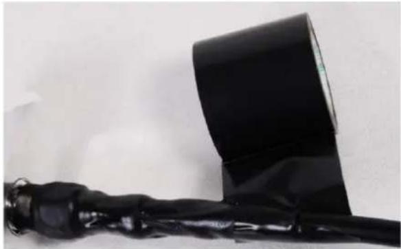
natural_image
Close-up of a black mechanical device with a curved black component attached, lying on a white surface (no text or symbols visible)8 Repeat with a further four layers of 19 mm (0.75 inch) PVC tape, always overlapping at half width. Wrap the layers in alternate directions:
• Second layer: top to bottom.
• Third layer: bottom to top.
• Fourth layer: top to bottom.
- Fifth layer: bottom to top.
The bottom edge of each layer should be 25 mm (1 inch) below the previous layer.
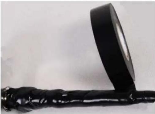
natural_image
Close-up of a black mechanical tool with a curved handle and a circular lens-like object attached (no text or symbols visible)9 Check the completed weatherproof connection:

natural_image
Close-up of a black cylindrical object with a flanged end, possibly a tool or device (no visible text or symbols)Replacing PSU fuses
The AC+DC Enhanced Power Injector 56V contains two replaceable fuses. These fuses protect the positive and negative grounded DC Configure voltages. If an incorrect power supply (that is, not in the range 37V to 60V DC) is connected to the DC Configure terminals, one or both fuses may blow.
Both fuses are 3 Amp slow-blow, for example Littlefuse part number 0229003.
To replace these fuses, undo the retaining screw and hinge back the cover as indicated:


Note No other fuses are replaceable in the AC+DC Enhanced Power Injector 56V.
This chapter describes how to use the web interface to configure the PTP 700 link. It also describes how to align antennas. This chapter contains the following topics:
• Preparing for configuration and alignment on page 6-2
• Connecting to the unit on page 6-4
• Using the web interface on page 6-6
• Standard Installation menu on page 6-12
• System menu on page 6-56
• Management menu on page 6-83
• SNMP pages (for SNMPv3) on page 6-106
• SNMP pages (for SNMPv1/2c) on page 6-115
• Security menu on page 6-122
- Configuring security for FIPS 140-3 applications on page 6-137
• External Devices on page 6-140 for integrated management of the TD-90 antenna positioner
• Aligning fixed beam antennas on page 6-144
• Other configuration tasks on page 6-154
Preparing for configuration and alignment
This section describes the checks to be performed before proceeding with unit configuration and antenna alignment.
Safety precautions
All national and local safety standards must be followed while configuring the units and aligning the antennas.

Warning Ensure that personnel are not exposed to unsafe levels of RF energy. The units start to radiate RF energy as soon as they are powered up. Respect the safety standards defined in Compliance with safety standards on page 4-2, in particular the minimum separation distances.
Observe the following guidelines:
- Never work in front of the antenna when the ODU is powered.
- Always power down the PSU before connecting or disconnecting the drop cable from the PSU, ODU or LPU.
Regulatory compliance
All applicable radio regulations must be followed while configuring the units and aligning the antennas. For more information, refer to Compliance with radio regulations on page 4-5.

Attention If the system designer has provided a list of channels to be barred for TDWR radar avoidance, the affected channels must be barred before the units are allowed to radiate on site, otherwise the regulations will be infringed. To bar these channels, follow the procedure Barring channels on page 7-47.
Selecting configuration options
Use the installation report to determine which configuration options are required. Refer to LINKPlanner on page 3-24.
Generating license keys
To obtain License Keys for capabilities that are not factory-installed, proceed as follows:
1 Identify and purchase the required entitlement for additional capabilities by referring to ODU capability upgrades on page 2-12.
2 Obtain the MAC Address of the ODU (it is on the System Status page).
3 Follow instructions, supplied in the email, to apply the entitlement to the ODU at the Cambium Networks support web site. Generated license keys are displayed in the License Keys page
Use the Software License Key page to configure the ODU with new license keys (Software License Key page on page 6-16).
Connecting to the unit
This section describes how to connect the unit to a management PC and power it up.
Configuring the management PC
Use this procedure to configure the local management PC to communicate with the PTP 700.
Procedure:
1 Select Properties for the Ethernet port. In Windows 7 this is found in Control Panel > Network and Internet > Network Connections > Local Area Connection.
2 Select Internet Protocol (TCP/IP):
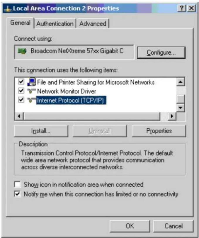
3 Click Properties.
4 Enter an IP address that is valid for the 169.254.X.X network, avoiding 169.254.0.0 and 169.254.1.1. A good example is 169.254.1.3:

5 Enter a subnet mask of 255.255.0.0. Leave the default gateway blank.
Connecting to the PC and powering up
Use this procedure to connect a management PC and power up the PTP 700.
Procedure:
1 Check that the ODU and PSU are correctly connected.
2 Connect the PC Ethernet port to the LAN port of the PSU using a standard (not crossed) Ethernet cable.
3 Apply mains or battery power to the PSU. The green Power LED should illuminate continuously.
4 After about 45 seconds, check that the orange Ethernet LED starts with 10 slow flashes.
5 Check that the Ethernet LED then illuminates continuously. If the Power and Ethernet LEDs do not illuminate correctly, refer to Testing link end hardware on page 8-7.
Using the web interface
This section describes how to use the PTP 700 web-based management interface to create a user account, to log in, and to use the various menu options provided.
Creating a user account
Use this procedure to set a password for the web interface when:
- The ODU is accessed for the first time.
- Configuration data has been erased.
- SSPs (including passwords) have been zeroized.
If Identity Based User Accounts is Enabled, the ODU prompts for a username and password, and creates an initial user account with the Security Officer user role.
Procedure:
1 Start the web browser from the management PC.
2 Type the IP address of the unit into the address bar. The factory default IP address is 169.254.1.1. Press ENTER.
3 By default, Identity Based User Accounts is Disabled, and the set password dialog is displayed with only the Password and Confirm Password controls. Enter and confirm a new password of between eight and 31 characters.
Click Set Password to access the web-based interface.

If Identity Based User Accounts is Enabled, the create user account dialog is displayed with Username, Password and Confirm Password controls. Enter a valid username and new password. The password must comply with the configured password complexity rules. By default, the minimum password length is eight characters. In FIPS Approved mode, the minimum password length is at least 15 characters.
Click Create User Account to access the web-based interface.

Logging into the web interface
Use this procedure to log into the web interface if a user account has already been created.
Procedure:
1 Start the web browser from the management PC.
2 Type the IP address of the unit into the address bar. The factory default IP address is 169.254.1.1. Press ENTER.
3 By default, Identity Based User Accounts is Disabled, and the login dialog is displayed with only the Password control. Enter the password.
Click Login to access the web-based interface.

If Identity Based User Accounts is Enabled, the login dialog is displayed with User Name and Password controls. Enter a valid username and password.
Click Login to access the web-based interface.

If Single Sign On is Enabled, the login dialog is displayed with User Name and Password controls, and an additional Single Sign On button. Click Single Sign On for SSO authentication, or enter a valid username and password and click Login for local authentication.

Using the menu options for the standard web interface
The standard web interface is displayed when Identity Based User Accounts is Disabled, or when a user with the Security Officer, System Administrator or Read Only user roles is logged in. A simplified web interface is displayed when a user with the Installer user role is logged in. For menu options in the simplified web interface, refer to Using the menu options for the simplified web interface on page 6-11.
Use the menu navigation bar in the left panel to navigate to each web page. Some of the menu options are only displayed for specific system configurations. Use Table 164 to locate information about using each web page.
Table 164 Menu options and web pages in the standard web interface
| Main menu | Menu option | Web page information |
| Home | System Summary page on page 7-2 | |
| Status | Standard System Status page on page 7-3 | |
| Alarms | Alarms on page 7-24 | |
| System | ||
| Configuration | System Configuration page on page 6-56 | |
| LAN Configuration | LAN Configuration page on page 6-60 | |
| QoS Configuration | QoS Configuration page on page 6-70 | |
| SFP Configuration | SFP Configuration page on page 6-73 | |
| Whitelist Configuration | Authorization Control page on page 6-75 | |
| Save and Restore | Save and Restore Configuration page on page 6-77 | |
| Reset Configuration | Reset Configuration page on page 6-79 | |
| Spectrum Expert or Spectrum Management | Spectrum Management on page 7-32 | |
| Statistics | System Statistics page on page 7-59Comparing actual to predicted performance on page 6-149 | |
| Wireless Port Counters | Wireless Port Counters page on page 7-65Test Ethernet packet errors reported by ODU on page 8-11 | |
| Main Port Counters | Main Port Counters page on page 7-68 | |
| Aux Port Counters | Aux Port Counters page on page 7-70 | |
| SFP Port Counters | SFP Port Counters page on page 7-71 | |
| SyncE Status | SyncE Status page on page 7-73 | |
| Diagnostics Plotter | Diagnostics Plotter page on page 7-76 | |
| CSV Download | Generate Downloadable Diagnostics page on page 7-78 | |
| Cable Diagnostics | Cable Diagnostics on page 8-2 | |
| Software Upgrade | Software Upgrade page on page 6-80 | |
| Reboot | Reboot Wireless Unit page on page 7-22 | |
| Installation | Standard Installation menu on page 6-12 | |
| Graphical Install | Graphical Install page on page 6-147 | |
| Management | ||
| Web | Web-Based Management page on page 6-83 | |
| Local User Accounts | Local User Accounts page on page 6-85 | |
| RADIUS Configuration | RADIUS Configuration page on page 6-89 | |
| SSO Configuration | SSO Configuration page on page 6-91 | |
| Login Information | Login Information page on page 7-22 | |
| Web Properties | Webpage Properties page on page 6-92 | |
| SNMP | SNMP pages (for SNMPv3) on page 6-106 | |
| SNMP pages (for SNMPv1/2c) on page 6-115 | ||
| Email Configuration page on page 6-95 | ||
| Instant Messaging | Instant Messaging page on page 6-97 | |
| Diagnostic Alarms | Diagnostic Alarms page on page 6-98 | |
| Time | Time Configuration page on page 6-99 | |
| Syslog | Syslog page on page 7-28 | |
| Syslog Configuration | Syslog Configuration page on page 6-104 | |
| Template Manager | Template Manager on page 6-119 | |
| Security | Security menu on page 6-122 | |
| Zeroize SSPs | Zeroize SSPs page on page 6-147 | |
| External Devices | ||
| TD90 | ||
| System Summary | System Summary on page 6-140 | |
| System Setup | System Setup on page 6-140 | |
| Manual Control | Manual Control on page 6-141 | |
| Positioner Configuration | Positioner Configuration on page 6-142 | |
| Software Upgrade | Firmware Upgrade on page 6-142 | |
| Compass Setup | Compass Setup on page 6-142 | |
| Errors | Errors on page 6-143 | |
| Reboot | Reboot on page 6-143 | |
| Change Password | Change Password page on page 7-23 | |
| Logout | Logging out on page 7-23 | |
Using the menu options for the simplified web interface
The simplified web interface (Figure 118) is displayed when a user with the Installer user role is logged in. For menu options in the standard web interface, refer to Using the menu options for the standard web interface on page 6-8.
Use the menu navigation bar in the left panel to navigate to each web page. Use Table 165 to locate information about using each web page.
Figure 118 Navigation bar in the simplified web interface

Table 165 Menu options and web pages in the simplified web interface
| Main menu | Web page information |
| Status | Simplified System Status page on page 7-17 |
| Installation | Simplified Installation menu on page 6-47 |
| Change Password | Change Password page on page 7-23 |
| Logout | Logging out on page 7-23 |
Standard Installation menu
This section describes how to use the Installation Wizard to complete the essential system configuration tasks that must be performed on a new link.

Attention If the system designer has provided a list of channels to be barred for TDWR radar avoidance, the affected channels must be barred before the units are allowed to radiate on site, otherwise the regulations will be infringed. To bar these channels, follow the procedure Barring channels on page 7-47.
Starting the Installation Wizard
To start the Installation Wizard: on the menu, click Installation. The response depends upon the state of the unit:
- If the unit is newly installed, the Software License Key page is displayed. Continue at Software License Key page on page 6-16.
- If the unit is armed for alignment, the Disarm Installation page is displayed. Continue at Disarm Installation page on page 6-13.
- If the unit is not armed, the Current Installation Summary page is displayed. Continue at Current Installation Summary page on page 6-13.
Disarm Installation page
Menu option: Installation (Figure 119). This page is displayed only when unit is armed.

Note The Installation agent cannot be armed (or disarmed) when the ODU operates as a Master in the HCMP topology.
Figure 119 Disarm Installation page (top and bottom of page shown)
Disarm Installation
The installation agent is armed. If you wish to disarm installation then use the 'Disarm Installation Agent' button. If you wish to reconfigure the installation agent then use the wizards 'back' button
License configuration
| Attributes | Value | Units |
| MAC Address | 00:04:56:58:00:d5 | |
| License Unit Serial Number | 5800D5 | |
| License Country | Development Key | |
| License Capacity | Full |
Installation Mode
| Installation Mode | Arm Without Tones | |
| Ranging Mode | Auto 0 to 40 km | |
| Disarm Installation Agent | ||

Back
To disarm the unit, click Disarm Installation Agent.
Current Installation Summary page
Menu option: Installation (Figure 120 and Figure 121). This page is displayed only when unit is not armed.
Figure 120 Current Installation Summary page (PTP topology)
Current Installation Summary
This page shows a summary of the current unit configuration.
Press the 'Continue to Installation Wizard' button below to change this configuration.
License configuration
| Attributes | Value | Units |
| MAC Address | 00:04:56:58:00:d5 | |
| License Unit Serial Number | 5800D5 | |
| License Country | Development Key | |
| License Capacity | Full | |
| Installation Configuration | ||
| IP Version | IPv4 | |
| IPv4 Address | 169.254.1.11 | |
| Subnet Mask | 255.0.0.0 | |
| Gateway IP Address | 169.254.0.0 | |
| Use VLAN For Management Interfaces | No VLAN Tagging | |
| DSCP Management Priority | 00 - DF | |
| Data Service | Main PSU Port | |
| Second Data Service | None | |
| Management Service | Main PSU Port | |
| Local Management Service | √ Out-of-Band Aux Port | |
| TDM Interface Control | None | |
| Wireless Configuration | ||
| Master Slave Mode | Master | |
| Access Method | Link Name Access | |
| Link Name | Ashburton to Widecombe | |
| Dual Payload | Enabled | |
| Max Receive Modulation Mode | 256QAM 0.81 | |
| Lowest Data Modulation Mode | BPSK 0.63 | |
| Link Mode Optimization | IP Traffic | |
| TDD Synchronization Mode | Disabled | |
| Regulatory Band | 8 - 5.4 GHz Unrestricted EIRP | |
| Channel Bandwidth | 15 | MHz |
| Link Symmetry | 1 to 1 | |
| Spectrum Management Control | DSO | |
| Extended Spectrum Scanning | Disabled | |
| Channel Raster | 5 | MHz |
| Lower Center Frequency | 5478 | MHz |
| Tx Color Code | A | |
| Rx Color Code | A | |
| Antenna Gain | 23.0 | dBi |
| Cable Loss | 0.0 | dB |
| Maximum Transmit Power | 23 | dBm |
| EIRP | 46.0 | dBm |
| ATPC Peer Rx Max Power | -35 | dBm |
| Installation Mode | ||
| Installation Mode | Arm Without Tones | |
| Ranging Mode | Auto 0 to 40 km | |
| Continue to Installation Wizard | ||
Click Continue to Installation Wizard.
Figure 121 Current Installation Summary page (HCMP topology)
Current Installation Summary
This page shows a summary of the current unit configuration.
Press the 'Continue to Installation Wizard' button below to change this configuration.
License configuration
| Attributes | Value | Units |
| MAC Address | 00:04:56:58:00:58 | |
| License Unit Serial Number | 580058 | |
| License Country | Development Key | |
| License Capacity | Full | |
| Installation Configuration | ||
| IP Version | IPv4 | |
| IPv4 Address | 169.254.1.11 | |
| Subnet Mask | 255.255.0.0 | |
| Gateway IP Address | 169.254.0.0 | |
| Use VLAN For Management Interfaces | No VLAN Tagging | |
| DSCP Management Priority | 00 - DF | |
| Data Service | Main PSU Port + SFP Port | |
| Management Service | In-Band | |
| Local Management Service | √ None √ In-Band | |
| Wireless Configuration | ||
| Wireless Topology | High Capacity Multi-Point | |
| Master Slave Mode | Master | |
| Access Method | Group Access | |
| Group ID | 0 | |
| Dual Payload | Enabled | |
| Max Receive Modulation Mode | 256QAM 0 81 | |
| Lowest Data Modulation Mode | BPSK 0.63 | |
| Link Mode Optimization | IP Traffic | |
| HCMP Maximum Link Range | 24.0 | km |
| Maximum Number Of Slaves | 4 | |
| HCMP Link Symmetry | 1 to 1 | |
| Downlink Ratio | 50.0 | % |
| Maximum Downlink Capacity | 80.42 | Mbps |
| Maximum Uplink Capacity | 80.42 | Mbps |
| TDD Frame Duration | 5495 | μs |
| TDD Synchronization Mode | Disabled | |
| Antenna Selection | Connectorized | |
| Connectorized Antenna Type | Directional, Integrated flat plate | |
| Regulatory Band | 81 - 4.7 GHz | |
| Channel Bandwidth | 20 | MHz |
| Spectrum Management Control | Fixed Frequency | |
| Extended Spectrum Scanning | Disabled | |
| Channel Raster | 5 | MHz |
| Fixed Transmit Frequency | 4410 | MHz |
| Tx Color Code | A | |
| Fixed Receive Frequency | 4410 | MHz |
| Rx Color Code | A | |
| Antenna Gain | 23.0 | dBi |
| Cable Loss | 0.0 | dB |
| Maximum Transmit Power | 27 | dBm |
| EIRP | 50.0 | dBm |
| Atpc Hcmp Master Target Rx Power | -56 | dBm |
| Installation Mode | ||
| Installation Mode | Arm Without Tones | |
| Ranging Mode | Auto 0 to 40 km | |
| Continue to Installation Wizard | ||
Click Continue to Installation Wizard.
Software License Key page
Menu option: Installation. Use this page to configure the unit with a new License Key and to review the capabilities of an installed License Key. The appearance of this page varies depending upon which capabilities are enabled by the entered license key. For example, Figure 122 shows the licensed capabilities for a PTP 700 in the USA market with a Full Capability Trial License, whereas Figure 123 shows IPv6 and other capabilities. Use the Cambium Networks License Key Generator to generate new License Keys (Generating license keys on page 6-2).
Figure 122 Software License Key page (PTP 700 USA market)
Software License Key
A valid software license key is required before installation of the PTP (Point to Point) wireless link can commence. To obtain a license key, please follow the instructions in the user guide.
License key data entry
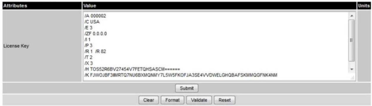
Full capability trial license
| Attributes | Value | Units |
| License Full Capability Trial Status | Active | |
| Trial Period Remaining | 60 | Days |
| Stop Full Capability Trial License | No Yes |
Capability summary
| Attributes | Value | Units |
| MAC Address | 00:04:56:00:00:02 | |
| License Unit Serial Number | 000002 | |
| License Country | USA | |
| License Number Of Regulatory Bands | 2 | |
| License Regulatory Bands List 1 | 1 - 5.8 GHz | |
| License Regulatory Bands List 2 | 82 - 4.7 GHz | |
| License Encryption | AES 256-bit (Rijndael) | |
| License SFP Port Support | Enabled | |
| License Auxiliary Port Support | Enabled | |
| License Capacity | Lite | |
| License IEEE1588 Support | Enabled | |
| License Sync E Support | Enabled | |
| License IPv6 Support | Enabled | |
| License TDD Sync Support | Enabled | |
Figure 123 Software License Key page (IPv6 and other capabilities)
Software License Key
A valid software license key is required before installation of the PTP (Point to Point) wireless link can commence. To obtain a license key, please follow the instructions in the user guide.
License key data entry

Capability summary
| Attributes | Value | Units |
| MAC Address | 00:04:56:00:00:02 | |
| License Unit Serial Number | 000002 | |
| License Country | Development Key | |
| License Number Of Regulatory Bands | 6 | |
| License Regulatory Bands List 1 | 1 - 5.8 GHz | |
| License Regulatory Bands List 2 | 13 - 5.4 GHz | |
| License Regulatory Bands List 3 | 14 - 4.9 GHz Public Safety | |
| License Regulatory Bands List 4 | 25 - 5.8 GHz ETSI | |
| License Regulatory Bands List 5 | 26 - 5.4 GHz ETSI | |
| License Regulatory Bands List 6 | 255 | |
| License Group Access | Enabled | |
| License OOB Management Support | Enabled | |
| License Capacity | Full | |
| License Max Number Of TDM Channels | 8 | |
| License IEEE1588 Support | Enabled | |
| License Sync E Support | Enabled | |
| License IPv6 Support | Enabled | |
| License TDD Sync Support | Enabled |
Procedures:
To enter a new License Key, proceed as follows:
• To clear the existing License Key (if present), click Clear.
- To format the new License Key: copy it from the Cambium notification email, paste it into the License Key box and click Format. The page is redisplayed with the License Key formatted.
- To enter the new License Key, click Submit. The page is redisplayed with the Capability Summary updated.
Full capacity trial
To control the full capability trial, proceed as follows:
- If License Full Capability Trial Status is Available (Figure 124), start the full capability trial period by setting Activate Full Capability Trial License to Yes.
- If License Full Capability Trial Status is Active (Figure 125), suspend the full capability trial period by setting Stop Full Capability Trial License to Yes.
- If License Full Capability Trial Status is Inactive (Figure 126), resume the full capability trial period by setting Start Full Capability Trial License to Yes.
To continue with the Installation Wizard, click Next.
Figure 124 Software License Key page (extract) with full capability trial available
| Full capability trial license | ||
| Attributes | Value | Units |
| License Full Capability Trial Status | Available | |
| Activate Full Capability Trial License | No Yes | |
Figure 125 Software License Key page (extract) with full capability trial active
| Full capability trial license | ||
| Attributes | Value | Units |
| License Full Capability Trial Status | Active | |
| Trial Period Remaining | 60 | Days |
| Stop Full Capability Trial License | No Yes | |
Figure 126 Software License Key page (extract) with full capability trial inactive
| Full capability trial license | ||
| Attributes | Value | Units |
| License Full Capability Trial Status | Inactive | |
| Trial Period Remaining | 60 | Days |
| Start Full Capability Trial License | No Yes | |
Changing AES license
If Identity Based User Accounts is Enabled, only a user with the Security Officer user role is allowed to enter a replacement License Key that alters the AES license.
The ODU zeroizes SSPs when the AES license is changed.

Attention When SSPs have been zeroized, all user accounts are disabled, and the ODU is returned to the "first use" condition. See Creating a user account on page 6-6 to create a new user account for the web-based interface.
Wireless Topology Configuration page
Menu option: Wireless Topology. Use this page to update Wireless Topology and Master Slave Mode.
The appearance of this page varies depending upon which capabilities have been enabled by license key. The HCMP option is only available if enabled in the license key.
Procedure:
- Review and update the Wireless Topology.
- Review and update the Master Slave Mode.
- If Wireless Topology = Point To Point, review and update Protection Mode.
• If Protection Mode = Hot Standby Primary, review and update Hot Standby Preference.
Figure 127 Wireless Topology page

Interface Configuration page
Menu option: Installation. Use this page to update the IP interface attributes.
The appearance of this page varies depending upon which capabilities have been enabled by license key. For example, Figure 128 shows the attributes that are displayed when IPv6, Aux Port, SFP Port and Out-of-Band Management support are enabled.

Attention Before configuring a VLAN for management interfaces, ensure that the VLAN is accessible, otherwise the unit will be inaccessible after the next reboot.
Note Synchronous Ethernet and IEEE 1588 Transparent Clock are disabled when TDM is enabled (LAN Configuration page on page 6-60).
Procedure:
• Review and update the IP and VLAN attributes (Table 166).
• To continue with the Installation Wizard, click Next or Submit Interface Configuration.
Figure 128 Interface Configuration page (IPv6, Aux, SFP, and OOB support)
Interface Configuration
Please complete the wizard in order to arm the unit.
A valid IP address and subnet mask is required before this unit can be used on a network. Please see your network administrator if you are unsure of the correct values to enter here.
Interface configuration data entry
| Attributes | Value | Units | |||
| IP Version | IPv4 | IPv6 | Dual IPv4 and IPv6 | ||
| IPv4 Address | 10 | 130 | 159 | 44 | |
| Subnet Mask | 255 | 255 | 254 | 0 | |
| Gateway IP Address | 10 | 130 | 159 | 254 | |
| IPv6 Address | 2001:cdba:0000:0000:0000:0000:3257:9652 | ||||
| IPv6 Prefix Length | 64 | ||||
| IPv6 Gateway Address | |||||
| IPv6 Auto Configured Link Local Address | |||||
| DNS Resolver | Disabled Enabled | ||||
| DNS Primary Server | Server 1 Server 2 | ||||
| DNS Server 1 Internet Address | 10.130.159.99 | ||||
| DNS Server 1 Port Number | 53 | ||||
| DNS Server 2 Internet Address | 10.130.159.98 | ||||
| DNS Server 2 Port Number | 53 | ||||
| Use VLAN For Management Interfaces | No VLAN Tagging | ||||
| DSCP Management Priority | 00 - DF | ||||
| Data Service | Main PSU Port + Aux Port | ||||
| Management Service | In-Band | ||||
| Local Management Service | Out-of-Band SFP Port | ||||
| Submit Interface Configuration Reset Form | |||||
Figure 129 Interface Configuration page (Hot Standby support)
Interface Configuration
Please complete the wizard in order to arm the unit.
A valid IP address and subnet mask is required before this unit can be used on a network. Please see your network administrator if you are unsure of the correct values to enter here.
Interface configuration data entry

Figure 130 Interface Configuration page (TD-90 support)
Interface Configuration
Please complete the wizard in order to arm the unit.
A valid IP address and subnet mask is required before this unit can be used on a network. Please see your network administrator if you are unsure of the correct values to enter here.
Interface configuration data entry
| Attributes | Value | Units | |||
| IP Version | IPv4 | IPv6 | Dual IPv4 and IPv6 | ||
| IPv4 Address | 10 | 130 | 159 | 44 | |
| Subnet Mask | 255 | 255 | 254 | 0 | |
| Gateway IP Address | 10 | 130 | 159 | 254 | |
| DNS Resolver | Disabled Enabled | ||||
| DNS Primary Server | Server 1 Server 2 | ||||
| DNS Server 1 Internet Address | 10.130.159.99 | ||||
| DNS Server 1 Port Number | 53 | ||||
| DNS Server 2 Internet Address | 10.130.159.98 | ||||
| DNS Server 2 Port Number | 53 | ||||
| Use VLAN For Management Interfaces | No VLAN Tagging | ||||
| DSCP Management Priority | 00 - DF | ||||
| TD90 Service | SFP Port | ||||
| Data Service | Main PSU Port | ||||
| Management Service | In-Band | ||||
| Local Management Service | Out-of-Band Aux Port | ||||
| Submit Interface Configuration Reset Form | |||||
Table 166 Interface Configuration attributes
| Attribute | Meaning |
| IP Version | The internet protocols to be supported by this ODU:IPv4: IPv4 protocols only. IPv4 attributes are displayed.IPv6: IPv6 protocols only. IPv6 attributes are displayed.Dual IPv4 and IPv6: Both IPv4 and IPv6 protocols. IPv4 and IPv6 attributes are displayed. |
| IPv4 Address | The IPv4 internet protocol address. This address is used by the family of Internet protocols to uniquely identify this unit on a network. |
| Subnet Mask | The address range of the connected IPv4 network. |
| Gateway IP Address | The IPv4 address of a computer on the current network that acts as an IPv4 gateway. A gateway acts as an entrance and exit to frames from and to other networks. |
| IPv6 Address | The IPv6 internet protocol address. This address is used by the family of Internet protocols to uniquely identify this unit on a network. |
| IPv6 Prefix Length | Length of the IPv6 subnet prefix (default 64 bits). |
| IPv6 Gateway Address | The IPv6 address of a computer on the current network that acts as an IPv6 gateway. A gateway acts as an entrance and exit to frames from and to other networks. It is usual to use the link-local address of the gateway. |
| IPv6 Auto Configured Link Local Address | The link-local address of the IPv6 gateway (displayed only, not updateable). |
| DNS Resolver | Options for using the internal DNS Resolver:Disabled: The DNS Resolver is not used.Enabled: The DNS Resolver is used. |
| DNS Primary Server | Select Server 1 or Server 2 as the Primary Server. The selected server will be used to resolve addresses configured as FQDNs to IPv4 or IPv6. The Secondary Server will be used if the Primary Server is not available. |
| DNS Server 1 Internet Address | The IPv4 or IPv6 address of DNS Server 1. |
| DNS Server 1 Port Number | The UDP Port Number used by DNS Server 1. The default is Port 53. |
| DNS Server 2 Internet Address | The IPv4 or IPv6 address of DNS Server 2. |
| DNS Server 2 Port Number | The UDP Port Number used by DNS Server 2. The default is Port 53. |
| Use VLAN For Management Interfaces | VLAN tagging options for the management interfaces:No VLAN TaggingIEEE 802.1Q Tagged (C-Tag, Type 8100)IEEE 802.1ad Tagged (S-Tag or B-Tag, Type 88a8)Ensure that the configured VLAN is accessible, otherwise it will not be possible to access the unit following the next reboot.The PTP 700 management function is only compatible with single VLAN tagged frames. Any management frame with two or more tags will be ignored. |
| VLAN Management VID | Only displayed when Use VLAN for Management Interfaces is not set to No VLAN Tagging.The VLAN VID (range 0 to 4094) that will be included in Ethernet frames generated by the management interfaces. |
| VLAN Management Priority | Only displayed when Use VLAN for Management Interfaces is not set to No VLAN Tagging.The VLAN priority (range 0 to 7) that will be included in Ethernet frames generated by the management interfaces. |
| DSCP Management Priority | Differentiated Services Code Point (DSCP) value to be inserted in the IP header of all IP datagrams transmitted by the management interface. |
| TD90 Service | The port allocation for the TD-90 Service for integrated management of the TD-90 antenna positioner.None: The TD-90 Service is disabledSFP Port: The TD-90 Service is enabled to use the SFP PortThe TD-90 Service cannot be enabled at an HCMP Master. |
| Protection Service | The port allocation for the Protection Service in Hot Standby links:Aux Port: The Protection Service uses the Aux PortSFP Port: The Protection Service uses the SFP Port |
| Data Service | The port allocation for the Data Service:Main PSU Port: The Data Service is connected to the Main PSU PortAux Port: The Data Service is connected to the Aux PortSFP Port: The Data Service is connected to the SFP PortMain PSU Port + Aux Port: The Data Service is connected to the Main PSU Port and the Aux PortMain PSU Port + SFP Port: The Data Service is connected to the Main PSU Port and the SFP PortAux Port + SFP Port: The Data Service is connected to the Aux Port and the SFP PortMain PSU Port + Aux Port + SFP Port: The Data Service is connected to the Main PSU, Aux Port and the SFP PortThe Data Service must always be assigned to at least one of the wired ports.For more help, see Ethernet port allocation on page 3-48. |
| Management Service | The port allocation for the end-to-end Management Service: None: The Management Service is not used. In-Band: The Management Service is connected to the port or ports allocated to the Data Service. Out-Of-Band Main PSU Port: The Management Service is connected to the Main PSU Port Out-Of-Band Aux Port: The Management Service is connected to the Aux Port Out-Of-Band SFP Port: The Management Service is connected to the SFP Port Out-Of-Band Main PSU Port + Aux Port: The Management Service is connected to the Main PSU Port and the Aux Port Out-Of-Band Main PSU Port + SFP Port: The Management Service is connected to the Main PSU Port and the SFP Port Out-Of-Band Aux Port + SFP Port: The Management Service is connected to the Aux Port and the SFP Port For more help, see Ethernet port allocation on page 3-48. |
| Local Management Service | Any port not already selected to the Data or Management Service is available for connection as an out-of-band port for the Local Management Service. Ports already selected to the Data or Management services are not displayed as options. For more help, see Ethernet port allocation on page 3-48. |
Configuring port allocations
The Interface Configuration page controls the allocation of the Main PSU Port, Aux Port and SFP Port to the Data Service, Management Service and Local Management Service.
PTP 700 supports exactly one instance of the Data Service, and this service is always mapped to one or more of the three wired ports. It is not possible to operate a link without any port selected to the Data Service.
PTP 700 supports zero or one instances of the optional Management Service. The Management Service can be used to access the management agent at the local unit. If the wireless link is established, the Management Service can also be used to access the management agent at the remote unit and other devices connected in the remote management network. The Management Service can be mapped to the set of ports that are already used for the Data Service to provide In-Band Management. Alternatively, the Management Service can be allocated to one or more dedicated ports to provide Out-of-Band Management.
PTP 700 also supports an optional Local Management Service, providing a connection from a wired port to the local management agent. Any port not already selected is available for selection to the Local Management Service. The Local Management Service does not connect across the wireless link.
The PTP 700 must always be manageable through one of three ports. Therefore, it is not possible to disable the Management Service unless at least one port is allocated to the Local Management Service.
For more details, see Ethernet port allocation on page 3-48.
Management Configuration page
Menu option: Management Configuration. Use this page to configure the cnMaestro device agent for connection to a cnMaestro server.
The appearance of the page depends on whether cnMaestro is configured, which type of server is selected, and which type of authentication is selected. See Figure 131 to Figure 133.
Figure 131 Management Configuration, cnMaestro disabled

Figure 132 Management Configuration, cnMaestro Cloud
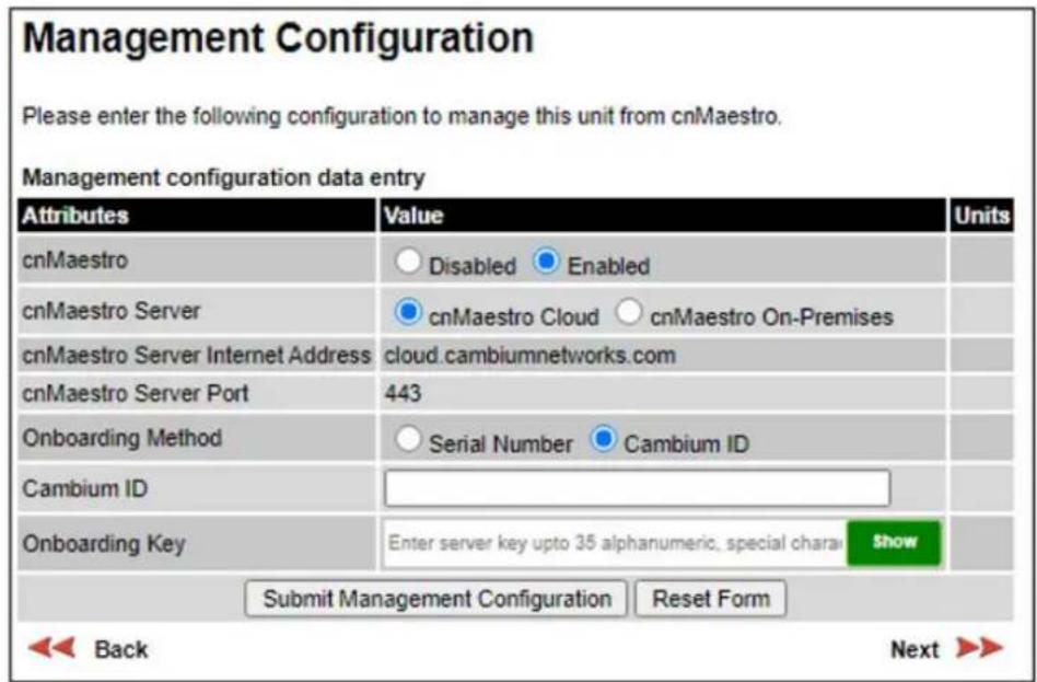
Figure 133 Management Configuration, cnMaestro On-Premises
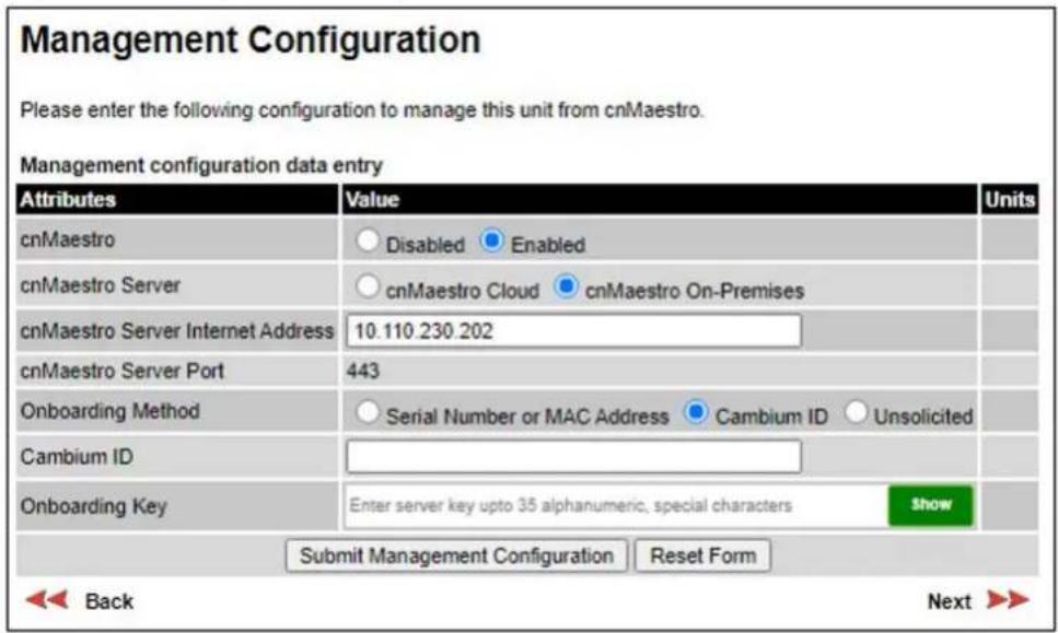
Table 167 Management Configuration attributes
| Attribute | Meaning |
| cnMaestro | Enabled: The cnMaestro device agent is enabled. Disabled: The cnMaestro device agent is disabled. |
| cnMaestro Server | cnMaestro Cloud: The device agent will connect to the Cloud server. cnMaestro On-Premises: The device agent will connect to an On-Premises server. |
| cnMaestro Server Internet Address | The Internet Address of the cnMaestro server. For a Cloud server, the address is always “cloud.cambiumnetworks.com”. For an On Premises server, configure the IPv4 address or FQDN of the server. |
| cnMaestro Server Port | The protocol port used by the HTTPS protocol. This is always 443. |
| Onboarding Method | Serial Number: The device is claimed by the cnMaestro user into an account using the device's MSN. The Serial Number option is hidden unless the ODU has a 12-character MSN. Cambium ID: The device agent is authenticated for onboarding using the operator's Cambium ID and secret Onboarding Key. This option supports Cloud and On-Premises servers. Serial Number or MAC Address: The device is claimed by the cnMaestro user into an account using the device's MSN or MAC Address. This option is hidden unless the ODU has a 12-character MSN. Unsolicited: The device is automatically onboarded into cnMaestro server. This option is supported for the On-Premises server only.Note 1: Cambium ID is not enabled by default in the cnMaestro On-Premises server. To use this onboarding method, enable authentication using Cambium ID at the server before the ODU attempts to connect.Note 2: A device can onboard into the cnMaestro On-Premises server in unsolicited mode only when authentication using Cambium ID is disabled at the server. |
| Cambium ID | The operator's Cambium ID entered as a text string of up to 60 characters. Cambium ID is erased automatically after successful onboarding. |
| Onboarding Key | The secret Onboarding Key associated with the Cambium ID entered as a text string of up to 35 characters. Onboarding Key is erased automatically after successful onboarding.If the ODU is subsequently removed from cnMaestro, the Onboarding Key must be entered again. |
Wireless Configuration page
Menu option: Installation (Figure 134 and Figure 135).
This page is part of the Installation Wizard. Use it to update the wireless attributes.
Figure 134 Wireless Configuration page (PTP topology)
Wireless Configuration
Please enter the following wireless configuration parameters.
Wireless data entry
| Attributes | Value | Units | ||||||
| Wireless Topology | Point To Point | |||||||
| Master Slave Mode | Master | |||||||
| Protection Mode | Disabled | |||||||
| Access Method | Link Access Link Name Access Group Access | |||||||
| Group ID | 123 | |||||||
| Dual Payload | Disabled Enabled | |||||||
| Max Receive Modulation Mode | 16QAM 0.63 | |||||||
| Lowest Data Modulation Mode | BPSK 0.63 | |||||||
| Link Mode Optimization | IP Traffic TDM Traffic | |||||||
| TDD Synchronization Mode | Disabled Enabled | |||||||
| Long Frame Duration | Disabled Enabled | |||||||
| Regulatory Band | 95 - 4.5 GHz | |||||||
| Channel Bandwidth | 45 MHz 40 MHz 30 MHz 20 MHz 15 MHz 10 MHz 5 MHz | |||||||
| Spectrum Management Control | DSO Fixed Frequency | |||||||
| Extended Spectrum Scanning | Disabled Enabled | |||||||
| Channel Raster | 5 | MHz | ||||||
| Lower Center Frequency | 4410.0 | MHz | ||||||
| Tx Color Code | A | |||||||
| Rx Color Code | A | |||||||
| Transmitter Channels | H and V H Only V Only | |||||||
| Maximum Transmit Power | 29 | dBm | ||||||
| ATPC Peer Rx Max Power | -35 | dBm | ||||||
| Link Registration Timeout | Disabled Enabled | |||||||
| Link Registration Timeout Period | 30 | minutes | ||||||
| Installation Mode | Arm With Tones Arm Without Tones Change Config Without Arming | |||||||
| Ranging Mode | Auto 0 to 40 km Auto 0 to 100 km Auto 0 to 200 km Auto 0 to 250 km Target Range | |||||||
| Submit Wireless Configuration Reset Form | ||||||||
Figure 135 Wireless Configuration page (HCMP topology)

Figure 136 Wireless Configuration page (Connectorized Antenna Type, HCMP topology)

Procedure:
- Update the attributes (Table 168).
- To save any changes and continue with the Installation Wizard, click Next or click Submit Wireless Configuration.

Attention The lower center frequency attribute must be configured to the same value for both the Master and Slave, otherwise the wireless link will fail to establish. The only way to recover from this situation is to modify the Lower Center Frequency attributes so that they are identical on both the master and slave units.

Note When configuring a linked pair of units, use the Master Slave Mode to ensure that one unit is Master and the other is Slave.
Table 168 Wireless Configuration attributes
| Attribute | Meaning | |
| Master Slave Mode | Master: The unit controls the point-to-point link and its maintenance. On startup, the Master transmits until a link with the Slave is made.Slave: The unit listens for its peer and only transmits when the peer has been identified. | |
| Protection Mode | Disabled: Hot Standby is disabled.Hot Standby Primary: The ODU is configured as the Primary ODU in a Hot Standby link.Hot Standby Secondary: The ODU is configured as the Secondary ODU in a Hot Standby link. | |
| Access Method | ODUs must be configured in pairs before a link can be established. Access Method determines how paired ODUs will recognize each other.Link Access: Each ODU must be configured with Target MAC Address equal to the MAC Address of the other unit.Link Name Access: Both ODUs must be configured with the same Link Name.Group Access: Both ODUs in a PTP link, and all ODUs in an HCMP sector, must be configured with the same Group ID attributes. Group Access is the only Access Method supported in the HCMP topology. | |
| Target MAC Address | Only displayed when Access Method is set to Link Access. This is the MAC Address of the peer unit that will be at the other end of the wireless link. This is used by the system to ensure the unit establishes a wireless link to the correct peer. The MAC Address can be found embedded within the serial number of the unit. The last six characters of the serial number are the last three bytes of the unit's MAC address. | |
| Link Name | Only displayed when Access Method is set to Link Name Access.Link Name may consist of letters (A-Z and a-z), numbers (0-9), spaces, and the following special characters: (,-,;<=>[ ]_{ }Link Name must be same at both ends and different to site name. | |
| Group ID | Only displayed when Access Method is set to Group Access. A link can only be established between units that have identical Group IDs. | |
| Dual Payload | Disabled:The link maximizes robustness against fading and interference.Enabled:The link attempts to reach maximum throughput at the expense of robustness against fading and interference. | |
| Max Receive Modulation Mode | The maximum mode the unit will use as its adaptive modulation. By default the Max Receive Modulation Mode is the highest mode available.For minimum error rates, set the maximum modulation mode to the minimum necessary to carry the required traffic. | |
| Lowest Data Modulation Mode | The lowest modulation mode that must be achieved before the link is allowed to bridge customer data Ethernet frames. This does not affect the bridging of management data: if out-of-band remote management is enabled, this will continue regardless of modulation mode. | |
| Link Mode Optimization | IP Traffic:The link is optimized for IP traffic to provide the maximum possible link capacity.TDM Traffic:The link is optimized for TDM traffic to provide the lowest possible latency. This is the only available setting when TDM is enabled (Interface Configuration page on page 6-19). | |
| TDD Synchronization Mode | Enabled:The ODU will synchronized the TDD frames at the wireless interface to an external or internal 1 Hz reference. | |
| Long Frame Duration | Always enabled for a PTP link in Hot Standby. Can optionally be enabled for an unprotected PTP link to provide synchronization between protected and unprotected links. | |
| Antenna Selection | Integrated:The unit uses the integrated antenna. The antenna connectors are disabled-connected:The unit uses the antenna connectors. The integrated antenna is disabled.This attribute is only displayed in a Connectorized+Integrated unit. | |
| Regulatory Band | The regulatory band selected from the list in the license key.Regulatory bands that require DFS (radar avoidance) are omitted from the list in this control if Long Frame Duration = Enabled. | |
| Connectorized Antenna Type | Only displayed in the HCMP topology, and only when the Regulatory Band applies different limits for PTP and PMP operation.Select one of the following for an HCMP Master:60 degrees sector90 degrees sector120 degrees sectorOmni-directionalOther | |
| Channel Bandwidth | 5 MHz, 10 MHz, 15 MHz, 20 MHz, 30 MHz, 40 MHz, 45 MHz: The bandwidth of the transmit and receive radio channels. | |
| Link Symmetry | Only displayed when Wireless Topology is set to Point To Point and Master Slave Mode is set to Master.Adaptive: Allows link symmetry to vary dynamically in response to offered traffic load. This is not supported in the following cases:Where radar avoidance is mandated in the region.Link Mode Optimization is set to TDM Traffic.“5 to 1”, “3 to 1, “2 to 1”, “1 to 1”, “1 to 2”, “1 to 3” or “1 to 5”: There is a fixed division between transmit and receive time in the TDD frame of the master ODU. The first number in the ratio represents the time allowed for the transmit direction and the second number represents the time allowed for the receive direction. The appropriate matching Link Symmetry is set at the slave ODU automatically. For example, if Link Symmetry is set to “2 to 1” at the master ODU, then the slave ODU will be set automatically as “1 to 2”. In this example, the master-slave direction has double the capacity of the slave-master direction.When TDM is enabled (Interface Configuration page on page 6-19), Link Symmetry is limited to “1 to 1”. | |
| Spectrum Management Control | PTP topologyIn regions that do not mandate DFS (radar detection), the options are:DSOFixed FrequencyIn regions that mandate DFS (radar detection), the options are:DFSDFS with DSOThis attribute is disabled if the regulatory requirement is fixed frequency only. | |
| HCMP topologyThe options are:DSOFixed Frequency | ||
| Slave Scan | Only displayed at an HCMP Slave ODU.Disabled: The Slave will be configured with fixed frequencies.Auto Single: The SlaveAuto Optimum: The Slave | |
| Extended Spectrum Scanning | Enables scanning of the entire frequency spectrum supported by the device (4400 MHz to 5875 MHz, 7125 MHz to 8500 MHz).Disabled: The extended Spectrum Scanning is disabled.Enabled: The extended Spectrum Scanning is enabled. | Attention Extended Spectrum Scanning decreases DSO performance. Do not leave Extended Spectrum Scanning enabled during normal operation. |
| Lower Center Frequency | The center frequency (MHz) of the lowest channel that may be used by this link. Not displayed when Spectrum Management Control is set to Fixed Frequency.Use this attribute to slide the available channels up and down the band. | |
| Default Raster | This is only displayed when Spectrum Management Control is set to Fixed Frequency. Limits frequency selection to the unit's default raster setting. | |
| Fixed Tx Frequency, Fixed Rx Frequency | This is only displayed when Spectrum Management Control is set to Fixed Frequency. The settings must be compatible at each end of the link. Once configured, the spectrum management function will not attempt to move the wireless link to a channel with lower co-channel or adjacent channel interference. Therefore, this mode of operation is only recommended for deployments where the installer has a good understanding of the prevailing interference environment. | |
| Tx Color Code, Rx Color Code | Tx Color Code and Rx Color Code may be used to minimize interference in a dense network of synchronized PTP 700 units where some of the units are operating on the same frequency. When this type of network is designed, the Color Code values are normally specified in the link planning report. In all other cases, Cambium Networks recommend that Tx Color Code and Rx Color Code are left at the default value of A.The value of Tx Color Code MUST always match the value of Rx Color Code at the other end of the link. | |
| Antenna Gain | Only displayed for a Connectorized ODU, or a Connectorized+Integrated ODU where Anntena Selection is set to Connectorized.Gain of the remote antenna. | |
| Cable Loss | Only displayed for a Connectorized ODU, or a Connectorized+Integrated ODU where Anntena Selection is set to Connectorized.Loss in the ODU-antenna RF cable. If there is a significant difference in length of the RF cables for the two antenna ports, then the average value should be entered. | |
| Automatic Alignment | Enables automatic alignment in a Beam Steering ODU. | |
| Transmitter Channels | Only displayed when the Transmitter Channels Control attribute is enabled (see Webpage Properties page on page 6-92).H and V: The ODU transmits on Horizontal and Vertical polarisationH Only: The ODU transmits on Horizontal polarisation (or at the H output of a Connectorized unit) only.V Only: The ODU transmits on Vertical polarisation (or at the V output of a Connectorized unit) only. | |
 | Note Operation using a single polarisation cannot provide polarisation diversity or polarisation multiplexing. This will reduce availability in non-line-of-sight paths and will reduce capacity in line-of-sight or near-line-of-sight paths. | |
| Maximum Transmit Power | The maximum power (dBm) at which the unit will transmit, configurable in steps of 1 dB. Its maximum value is controlled by the combination of the selected Regulatory Band, Bandwidth and (for connectorized units) Antenna Gain and Cable Loss.Set this attribute to the value specified in the installation report (LINKPlanner). | |
 | Note Maximum Transmit Power is the maximum combined power for the normal case where H and V channels operate together.When Transmitter Channels is set to H Only or V Only, the maximum transmitted power will be 3 dB lower than the configured Maximum Transmit Power. | |
| ATPC Peer Rx Max Power | This attribute is only displayed if:The unit is in PTP topologyThe operating regulatory band does not require radar detection.Set this attribute to the maximum receive power the ATPC mechanism must try to achieve at the peer unit. | |
| ATPC HCMP Master Transmit Power | This attribute is only visible if the unit is configured as an HCMP Slave.This attribute must be set to the same value as the Maximum Power Power on the HCMP Master. | |
 | Note The wireless link may fail to establish if the value of this attribute is not set as recommended. | |
| ATPC HCMP Master Target Receive Power | This attribute is only visible if Wireless Topology is set to HCMP.This determines the HCMP Master receive power the ATPC mechanism on the HCMP Slave must try to reach. | |
 | Note Setting a high value may reduce sensitivity of the HCMP Master to low receive signal while setting it low value may prevent the HCMP Master to reach top rate mode.The default value of -56 dBm ensures that the top modulation mode can be reached whilst not degrading the performance at low receive signal level. | |
| Link Registration Timeout | Only displayed when the Configure Link Registration Timeout Control is enabled (see Webpage Properties page on page 6-92).Disabled: The ODU remains in the acquisition state indefinitely if a wireless link is not established.Enabled: The ODU reboots if a wireless link is not established within the Link Registration Timeout Period. | |
| Link Registration Timeout Period | Only displayed if Link Registration Timeout is set to Enabled.The period in minutes (15..720) for the Link Registration Timeout. The default value is 15 minutes. | |
| Installation Mode | Arm With Tones: Audio tones will be emitted during antenna alignment (the recommended option). This option is not available if automatic alignment is enabled.Arm Without Tones: Audio tones will not be emitted during antenna alignment.Change Config Without Arming: Configuration changes will be made without arming the ODU for alignment. This is the only option supported for the Master ODU in HCMP topology. This option is not available in an ODU with automatic alignment enabled unless alignment has already been successfully completed. | |
| Ranging Mode | This can only be modified if the unit is operating in the PTP topology, and Installation Mode is Arm With Tones or Arm Without Tones.Auto.: During alignment, the wireless units use algorithms to calculate link range. To implement automatic ranging, select a value that corresponds to the estimated maximum range of the link:Auto 0 to 40 km (0 to 25 miles).Auto 0 to 100 km (0 to 62 miles).Auto 0 to 200 km (0 to 125 miles).Auto 0 to 250 km (0 to 156 miles).Target Range: During alignment, the wireless units use the approximate link distance (entered in Target Range) to calculate link range. The main advantage of Target Range mode is that it reduces the time taken by the units to range.If preferred, range functions can be configured to operate in miles, as described in Webpage Properties page on page 6-92. | |
| Target Range | Only available when Ranging Mode is set to Target Range.The approximate distance between the two wireless units to within ±1 km. Enter the same value at both ends of the link. | |
| HCMP Maximum Link Range | The maximum link range that will be supported for any link in an HCMP sector. Configure a value between 5.0 km and 100.0 km (3 miles to 62 miles). | |
TDD Frame page
The TDD Frame page (Figure 137) is displayed in the Installation Wizard page after the Wireless Configuration page when the ODU is operating in the HCMP topology.
Procedure:
- Update the attributes (Table 169).
- Click Next.
Figure 137 TDD Frame page (HCMP Master, Standard TDD Frame Configuration)
TDD Frame
Please enter the following TDD Frame parameters. In HCMP mode, the same parameters must be entered at both the Master and the Slaves.
TDD Frame data entry
| Attributes | Value | Units | ||||||||
| Maximum Number Of Slaves | 4✓ | |||||||||
| TDD Frame Configuration Mode | ○Standard Mode ○Expert Mode | |||||||||
| HCMP Link Symmetry | ○4 to 1 ●3 to 1 ○2 to 1 ○1 to 1 ○1 to 2 ○1 to 3 ○1 to 4 | |||||||||
| Downlink Ratio | 75.0 | % | ||||||||
| Total Downlink Capacity | 242.54 | Mbps | ||||||||
| Total Uplink Capacity | 80.84 | Mbps | ||||||||
| Submit TDD Frame Configuration Reset Form | ||||||||||
| Back Next ▶▶ | ||||||||||
Figure 138 TDD Frame page (HCMP Master, Expert TDD Frame Configuration)
TDD Frame
Please enter the following TDD Frame parameters. In HCMP mode, the same parameters must be entered at both the Master and the Slaves.
TDD Frame data entry

Figure 139 TDD Frame page (HCMP Slave, Standard TDD Frame Configuration)
TDD Frame
Please enter the following TDD Frame parameters. In HCMP mode, the same parameters must be entered at both the Master and the Slaves.
TDD Frame data entry
| Attributes | Value | Units |
| Maximum Number Of Slaves | 4 √ | |
| TDD Frame Configuration Mode | ◎ Standard Mode ○ Expert Mode | |
| HCMP Link Symmetry | ○ 4 to 1 ◎ 3 to 1 ○ 2 to 1 ○ 1 to 1 ○ 1 to 2 ○ 1 to 3 ○ 1 to 4 | |
| Downlink Ratio | 75.0 | % |
| Total Downlink Capacity | 242.54 | Mbps |
| Total Uplink Capacity | 80.84 | Mbps |
| Slave Downlink Capacity | 60.63 | Mbps |
| Slave Uplink Capacity | 20.21 | Mbps |
| Submit TDD Frame Configuration Reset Form | ||
| Back Next ➤ | ||
Figure 140 TDD Frame page (HCMP Slave, Expert TDD Frame Configuration)
TDD Frame
Please enter the following TDD Frame parameters. In HCMP mode, the same parameters must be entered at both the Master and the Slaves.
TDD Frame data entry
| Attributes | Value | Units |
| Maximum Number Of Slaves | 4 √ | |
| TDD Frame Configuration Mode | ○ Standard Mode ⊙ Expert Mode | |
| Downlink Timeslots in TDD period | 10 √ | |
| Uplink Timeslots in TDD period | 6 √ | |
| Slave Downlink Timeslots Request | 3 √ | |
| Slave Uplink Timeslots Request | 1 √ | |
| Slave Downlink Timeslots Limit | 9 √ | |
| Slave Uplink Timeslots Limit | 5 √ | |
| Downlink Ratio | 62.5 | % |
| Total Downlink Capacity | 202.12 | Mbps |
| Total Uplink Capacity | 121.27 | Mbps |
| Slave Downlink Capacity | 60.63 | Mbps |
| Slave Uplink Capacity | 20.21 | Mbps |
| Submit TDD Frame Configuration Reset Form | ||
Table 169 TDD Frame attributes
| Attribute | Meaning |
| Maximum Number Of Slaves | 2 to 8The maximum number of HCMP Slaves that can simultaneously connect to the HCMP Master.The same value must be used on the HCMP Master and all the HCMP Slaves that connect to it. |
| TDD Frame Configuration Mode | Standard, ExpertSelect Expert to configure individual time slot allocations to each Slave ODU. |
| HCMP Link Symmetry | Standard TDD Frame Configuration Mode only.“4 to 1”, “3 to 1, “2 to 1”, “1 to 1”, “1 to 2”, “1 to 3” or “1 to 4”: The ratio of capacity between the downlink direction and the uplink direction. |
| Downlink Ratio | The proportion of total (uplink and downlink) time slots assigned to the downlink as a percentage. |
| Total Downlink Capacity | The combined capacity for all downlink time slots assuming the highest modulation mode |
| Total Uplink Capacity | The combined capacity for all uplink time slots assuming the highest modulation mode |
| Downlink Timeslots in TDD PeriodUplink Timeslots in TDD Period | Expert TDD Frame Configuration Mode only.The number of downlink and uplink time slots configured in the TDD frame at the HCMP Master. |
| Slave Downlink Capacity | The capacity for downlink time slots assigned to the Slave ODU assuming the highest modulation mode |
| Slave Uplink Capacity | The capacity for uplink time slots assigned to the slave assuming the highest modulation mode |
| Slave Downlink Timeslots RequestSlave Uplink Timeslots Request | Expert TDD Frame Configuration Mode only.The number of downlink and uplink time slots requested for the Slave ODU. |
| Slave Downlink Timeslots LimitSlave Uplink Timeslots Limit | Expert TDD Frame Configuration Mode only.The maximum number of downlink and uplink time slots that can be assigned by dynamic allocation to the Slave ODU.See Dynamic time slot allocation in HCMP on page 1-35 |
TDD Synchronization page (optional)
If TDD Synchronization Mode is set to Enabled in the Wireless Configuration page, the TDD Synchronization page (Figure 141, Figure 142, Figure 143, Figure 144, Figure 145) is the fourth Installation Wizard page.
For more information on the available options, refer to Configuration options for TDD synchronization on page 3-36.
Procedure:
- Update the attributes (Table 170 and Table 171)
- Click Next.
Figure 141 TDD Synchronization page, PTP-SYNC, PTP topology
TDD Synchronization
Please enter the following TDD Synchronization parameters
TDD Synchronization data entry
| Attributes | Value | Units | ||
| TDD Sync Device | PTPSYNC Cambium Sync Injector | |||
| Cluster Master Slave | Cluster Master Cluster Slave | |||
| PTP Sync Site Reference | Internal GPS/1PPS External | |||
| Max Burst Duration Master To Slave | 1453▼ | μs | ||
| Max Burst Duration Slave To Master | 726▼ | μs | ||
| TDD Frame Duration | 2500▼ | μs | ||
| TDD Frame Offset | 0 | μs | ||
| Slave Receive To Transmit Gap | 39 | μs | ||
| TDD Holdover Mode | Strict Best Effort | |||
| TDD Holdover Duration | 1 | minutes | ||
| Submit TDD Synchronization Configuration Reset Form | ||||
Figure 142 TDD Synchronization page, direct connection, PTP topology
TDD Synchronization
Please enter the following TDD Synchronization parameters
TDD Synchronization data entry
| Attributes | Value | Units | ||
| TDD Sync Device | PTPSYNC Cambium Sync Injector | |||
| Cambium Sync Input Port | Internal Main PSU Aux | |||
| Cambium Sync Output Port | None Aux | |||
| Max Burst Duration Master To Slave | 726▼ | μs | ||
| Max Burst Duration Slave To Master | 1453▼ | μs | ||
| TDD Frame Duration | 2283▼ | μs | ||
| TDD Frame Offset | 0 | μs | ||
| Slave Receive To Transmit Gap | 39 | μs | ||
| TDD Holdover Mode | Strict Best Effort | |||
| TDD Holdover Duration | 1 | minutes | ||
| Submit TDD Synchronization Configuration Reset Form | ||||
Figure 143 TDD Synchronization page, PTP-SYNC, HCMP topology
TDD Synchronization
Please enter the following TDD Synchronization parameters
TDD Synchronization data entry
| Attributes | Value | Units |
| TDD Sync Device | PTPSYNC Cambium Sync Injector | |
| Cluster Master Slave | Cluster Master Cluster Slave | |
| PTP Sync Site Reference | Internal GPS/1PPS External | |
| TDD Frame Duration | 5495 | μs |
| TDD Frame Offset | 0 | μs |
| TDD Holdover Mode | Strict Best Effort | |
| TDD Holdover Duration | 10 | minutes |
| Submit TDD Synchronization Configuration Reset Form | ||
Figure 144 TDD Synchronization page, direct connection, HCMP topology

Figure 145 TDD Synchronization page, HCMP Slave


Note For units operating in the PTP topology, obtain the data required to populate this page using the LINKPlanner.
Table 170 TDD Synchronization attributes at a TDD Master or TDD Slave ODU
| Attribute | Meaning |
| Max Burst Duration | Displayed in PTP topology when the link is configured for Hot Standby link protection.The maximum duration of the burst transmitted by Master and Slave ODUs.For standard frame duration, select a value in the range 544 to 2176 microseconds.For long frame duration (including Hot Standby), select a value in the range 484 to 6528 microseconds. |
| Max Burst Duration Master to Slave | Displayed in PTP topology when the link is not operating in a DFS bandThe maximum duration of the burst transmitted by the Master ODU and received by the Slave ODU.The range of the control is the same as Max Burst Duration, described above. |
| Max Burst Duration Slave to Master | Displayed in PTP topology when the link is not operating in a DFS bandThe maximum duration of the burst transmitted by the Slave ODU and received by the Master ODU.The range of the control is the same as Max Burst Duration, described above. |
| TDD Frame Duration | Read only in HCMP topology.For PTP with standard frame duration, select a value in the range 1299 to 6410 microseconds.For PTP with long frame duration (including Hot Standby), select a value in the range 1250 to 14286 microseconds. |
| Slave Receive To Transmit Gap | Only displayed in PTP topology.The duration of the gap between receive and transmit at the slave ODU. |
Table 171 TDD Synchronization attributes at a TDD Master ODU
| Attribute | Meaning |
| TDD Sync Device | PTP-SYNC: The ODU will synchronize using the connected PTP-SYNC unit. This option is not available for PTP 78700 ODUs.Cambium Sync Injector: The ODU will synchronize using a direct connection to another ODU. |
| Cluster Master Slave | Only displayed when TDD Sync Device = PTP SYNCCluster Master: The first ODU in the synchronization chain.Cluster Slave: The second or subsequent ODU in the chain. |
| PTP-SYNC Site Reference | Only displayed when TDD Sync Device = PTP SYNCInternal: Standalone operation with no external timing reference.GPS/1PPS External: An external GPS receiver will provide a 1 pps timing reference. |
| Cambium Sync Configure Port | Only displayed when TDD Sync Device = Cambium Sync Injector.Internal: Free-running synchronization is generated internally.Main PSU: The ODU will synchronize to a 1PPS signal at the Main PSU port.Aux: The ODU will synchronize to a 1PPS signal at the Aux port. |
| Cambium Sync Output Port | Only displayed when TDD Sync Device = Cambium Sync Injector.None: The ODU will not output a synchronization signal.Aux: The ODU will output a synchronization signal at the Aux port. |
| TDD Frame Offset | The delay of the start of the TDD frame from the epoch of the external timing reference. This permits the design of synchronized networks in which the phase of the TDD frame is independent of the master/slave function. Enter a value in the range from zero to one microsecond less than the TDD Frame Duration. |
| TDD Holdover Mode | Strict: The unit will not transmit when synchronization is lost.Best Effort: The unit will synchronize when there is a reference signal, but otherwise will operate in unsynchronized mode. |
| TDD Holdover Duration | Specifies duration of holdover period following loss of the external timing reference for TDD synchronization. Default value 10 minutes, maximum 60 minutes. |
Confirm Installation Configuration page
Menu option: Installation (Figure 146). Use this page to review and confirm the updated wireless configuration of the unit.
Figure 146 Confirm Installation Configuration page (top and bottom of page shown)

Procedure:
• To undo or correct any updates, click Back.
- To confirm the updates and arm the installation, click Confirm Configuration and Reboot and click OK to reboot the unit.
- If IP Address, Subnet Mask or Gateway IP Address have been changed: reconfigure the local management PC to use an IP address that is valid for the network. Refer to Configuring the management PC on page 6-4.
• If IP Address has been changed, use the new IP address to log into the unit.
Simplified Installation menu
This section describes how to use the Installation Wizard to complete the essential system configuration tasks that must be performed on a new link.
Starting the Installation Wizard
To start the Installation Wizard: on the menu, click Installation. The response depends upon the state of the unit:
- If the unit is armed for alignment, the Disarm Installation page is displayed. Continue at Disarm Installation page on page 6-47.
- If the unit is not armed, the Current Installation Summary page is displayed. Continue at Current Installation Summary page on page 6-48.
Disarm Installation page
Menu option: Installation (Figure 147). This page is displayed only when unit is armed.

Note The Installation agent cannot be armed (or disarmed) when the ODU operates as a Master in the HCMP topology.
Figure 147 Disarm Installation page
Disarm Installation
The installation agent is armed. If you wish to disarm installation then use the 'Disarm Installation Agent' button. If you wish to reconfigure the installation agent then use the wizards 'back' button
| Attributes | Value | Units |
| Equipment Configuration | ||
| Unit Name | Tamalpais 2 | |
| Site Name | Mount Tamalpais | |
| Template Configuration | ||
| Configuration Template | Most Robust | |
| Master Slave Mode | Slave | |
| Wireless Configuration | ||
| Group ID | 0 | |
| Maximum Transmit Power | 29 | dBm |
| Installation Mode | Arm Without Tones | |
| Interface Configuration | ||
| IP Version | IPv4 | |
| IPv4 Address | 10.130.159.48 | |
| Subnet Mask | 255.255.254.0 | |
| Gateway IP Address | 10.130.159.254 | |
| Disarm Installation Agent | ||

Back
To disarm the unit, click Disarm Installation Agent.
Current Installation Summary page
Menu option: Installation (Figure 148). This page is displayed only when unit is not armed.
Figure 148 Current Installation Summary page
Current Installation Summary
This page shows a summary of the current unit configuration.
Press the 'Continue to Installation Wizard' button below to change this configuration.
| Attributes | Value | Units |
| Equipment Configuration | ||
| Unit Name | Tamalpais 2 | |
| Site Name | Mount Tamalpais | |
| Template Configuration | ||
| Configuration Template | Most Robust | |
| Master Slave Mode | Slave | |
| Wireless Configuration | ||
| Group ID | 0 | |
| Maximum Transmit Power | 29 | dBm |
| Installation Mode | Change Config Without Arming | |
| Interface Configuration | ||
| IP Version | IPv4 | |
| IPv4 Address | 10.130.159.48 | |
| Subnet Mask | 255.255.254.0 | |
| Gateway IP Address | 10.130.159.254 | |
| Continue to Installation Wizard | ||
Click Continue to Installation Wizard.
Equipment Configuration page
Menu option: Installation. Use this page to update Unit Name and Site Name.
Procedure:
- Review and update the Unit Name.
- Review and update the Site Name.
Figure 149 Equipment Configuration page
Equipment Configuration
Please enter the following equipment configuration parameters.
Equipment configuration data entry
| Attributes | Value | Units |
| Unit ESN | 0004565800A8 | |
| Unit MSN | U9SD0B1ZP6J4 | |
| Unit SKU | C045070B003B | |
| Unit Name | Tamalpais 2 | |
| Site Name | Mount Tamalpais | |
| Submit Equipment Configuration Reset Form | ||
Table 172 Equipment Configuration attributes
| Attribute | Meaning |
| Unit ESN | The Electronic Serial Number of the ODU.Read Only. |
| Unit MSN | The Mechanical Serial Number of the ODU.Read Only. |
| Unit SKU | The Cambium Part Number of the ODURead Only. |
| Unit Name | Unit Name may consist of letters (A-Z and a-z), numbers (0-9), spaces, and the following special characters: (),-,:<=>[]_{}. Unit name should be unique within the wireless network. |
| Site Name | User defined name for the site, with additional notes (if required). |
Template Configuration page
Menu option: Installation. Use this page to update Template.
Procedure:
- Review and update the Template.
Figure 150 Template Configuration page

Table 173 Wireless Configuration attributes
| Attribute | Meaning |
| Template | Selects a predetermined standard template to address a range of likely deployment scenarios, or a custom template created by a Security Officer or System Administrator user.The standard templates are as follows:Best PerformanceBest RangeMost RobustHCMP |
Wireless Configuration page
Menu option: Installation. Use this page to update the wireless attributes.
Procedure:
- Update the Master Slave Mode, Link Name, Target MAC Address, Group ID, Maximum Transmit Power and Installation Mode attributes (Table 174).
- To save any changes and continue with the Installation Wizard, click Next or click Submit Wireless Configuration.
Figure 151 Wireless Configuration page

Table 174 Wireless Configuration attributes
| Attribute | Meaning |
| Wireless Topology | Point to point (PTP): A wireless link between one Master ODU and one Slave ODU.High-capacity multipoint (HCMP): A wireless network consisting of one Master ODU and betwtwen two and eight Slave ODUs.Read Only. |
| Master Slave Mode | Master: The unit controls the wireless link. On startup, the Master transmits until a link with the Slave is made.Slave: The unit listens for its peer and only transmits when the peer has been identified. |
| Target MAC Address | Only displayed when Access Method is set to Link Access. This is the MAC Address of the peer unit that will be at the other end of the wireless link. This is used by the system to ensure the unit establishes a wireless link to the correct peer. The MAC Address can be found embedded within the serial number of the unit. The last six characters of the serial number are the last three bytes of the unit's MAC address. |
| Link Name | Only displayed when Access Method is set to Link Name Access.Link Name may consist of letters (A-Z and a-z), numbers (0-9), spaces, and the following special characters: ( ),-,,<=>[]_{ }Link Name must be same at both ends and different to site name. |
| Group ID | A link can only be established between units that have identical Group IDs. |
| Spectrum Management Control | DSO: The ODU uses Dynamic Spectrum Optimization to automatically select the RF channel with the lowest interference.Fixed Frequency: The ODU is configured with fixed transit and receive frequencies. |
| Lower Centre Frequency | The center frequency (MHz) of the lowest channel that may be used by this link. Not displayed when Spectrum Management Control is set to Fixed Frequency. |
| Fixed Tx Frequency Fixed Rx Frequency | This is only displayed when Spectrum Management Control is set to Fixed Frequency. The settings must be compatible at each end of the link. Once configured, the spectrum management function will not attempt to move the wireless link to a channel with lower co-channel or adjacent channel interference. Therefore, this mode of operation is only recommended for deployments where the installer has a good understanding of the prevailing interference environment. |
| Maximum Transmit Power | The maximum power (dBm) at which the unit will transmit, configurable in steps of 1 dB. Its maximum value is controlled by the combination of the selected Regulatory Band, Bandwidth and (for connectorized units) Antenna Gain and Cable Loss.Set this attribute to the value specified in the installation report (LINKPlanner). |
| Attribute | Meaning | |
 | Note Maximum Transmit Power is the maximum combined power for the normal case where H and V channels operate together.When Transmitter Channels is set to H Only or V Only, the maximum transmitted power will be 3 dB lower than the configured Maximum Transmit Power. | |
| Installation Mode | Arm With Tones: Audio tones will be emitted during antenna alignment (the recommended option).Arm Without Tones: Audio tones will not be emitted during antenna alignment.Change Config Without Arming: Configuration changes will be made without arming the ODU for alignment. This is the only option supported for the Master ODU in HCMP topology. | |

Note When configuring a linked pair of units, use the Master Slave Mode to ensure that one unit is Master and the other is Slave.
Interface Configuration page
Menu option: Installation. Use this page to update the IP interface attributes.
Procedure:
• Review and update the IP interface attributes (Table 166).
• To continue with the Installation Wizard, click Next or Submit Interface Configuration.
Figure 152 Interface Configuration page

Table 175 Interface Configuration attributes
| Attribute | Meaning |
| IP Version | The internet protocols to be supported by this ODU:IPv4: IPv4 protocols only. IPv4 attributes are displayed.IPv6: IPv6 protocols only. IPv6 attributes are displayed.Dual IPv4 and IPv6: Both IPv4 and IPv6 protocols. IPv4 and IPv6 attributes are displayed.Read Only. |
| IPv4 Address | The IPv4 internet protocol address. This address is used by the family of Internet protocols to uniquely identify this unit on a network. |
| Subnet Mask | The address range of the connected IPv4 network. |
| Gateway IP Address | The IPv4 address of a computer on the current network that acts as an IPv4 gateway. A gateway acts as an entrance and exit to frames from and to other networks. |

Note The Interface Configuration will be Read Only if IP Configuration is not selected as an editable control in a custom template, or if the ODU has been configured to use the HTTPS interface.
Confirm Installation Configuration page
Menu option: Installation (Figure 153). Use this page to review and confirm the updated configuration of the unit.
Procedure:
• To undo or correct any updates, click Back.
- To confirm the updates and arm the installation, click Confirm Configuration and Reboot and click OK to reboot the unit.
- If IP Address, Subnet Mask or Gateway IP Address have been changed: reconfigure the local management PC to use an IP address that is valid for the network. Refer to Configuring the management PC on page 6-4.
• If IP Address has been changed, use the new IP address to log into the unit.
Figure 153 Confirm Installation Configuration page
Confirm Installation Configuration
Please review your entered configuration. If any of the configuration items are incorrect please use the back button to apply the corrections.
Once you're happy with the configuration press the 'Confirm Configuration and Reboot' button, this will commit the parameters to non-volatile memory and reboot this wireless unit.
| Attributes | Value | Units |
| Equipment Configuration | ||
| Unit Name | Colinas 6 | |
| Site Name | ||
| Template Configuration | ||
| Template | Test Template | |
| Master Slave Mode | Master | |
| Wireless Configuration | ||
| Access Method | Group Access | |
| Group ID | 0 | |
| Spectrum Management Control | Fixed Frequency | |
| Fixed Transmit Frequency | 4640.000 | MHz |
| Fixed Receive Frequency | 4640.000 | MHz |
| Maximum Transmit Power | 10 | dBm |
| Installation Mode | Arm Without Tones | |
| Interface Configuration | ||
| IP Version | IPv4 | |
| IPv4 Address | 10.130.159.44 | |
| Subnet Mask | 255.255.254.0 | |
| Gateway IP Address | 10.130.159.254 | |
| Confirm Configuration and Reboot | ||

Back
System menu
This section describes how to configure the IP and Ethernet interfaces of the PTP 700 unit.
System Configuration page
Menu option: System > Configuration (Figure 154). Use this page to enable AES encryption and to review and update key wireless attributes of the unit.
Figure 154 System Configuration page
| System Configuration This page controls the day to day configuration of this unit. | |||
| Attributes | Value | Units | |
| Equipment | |||
| Enable Transmission | Enabled | ||
| Mute Transmission | |||
| Link Name | Ashburton to Widecombe | ||
| Unit Name | Ashburton #1 | ||
| Site Name | Ashburton | ||
| Fully Qualified Domain Name | ashburton001.example-nwk.com | ||
| Latitude | 50.523611 | ||
| Longitude | -3.740833 | ||
| Altitude | 96 | ||
| IP Address Label | IPv4 Address | ||
| Wireless | |||
| Master Slave Mode | Master | ||
| Dual Payload | Enabled | ||
| Link Mode Optimization | IP Traffic | ||
| Channel Bandwidth | 20 | MHz | |
| Max Receive Modulation Mode | 256QAM 0.81✓ | ||
| Lowest Data Modulation Mode | BPSK 0.63✓ | ||
| Antenna Gain | 23.0 | dBi | |
| Cable Loss | 0.0 | dB | |
| Maximum Transmit Power | 29 | dBm | |
| ATPC Peer Rx Max Power | -35 | dBm | |
| Wireless Encryption | |||
| Encryption Algorithm | ○ None ○ TLS RSA ● TLS PSK 128-bit ○ TLS PSK 256-bit | ||
| Pre-shared Key | ********** | Show | |
| Confirm Pre-shared Key | ********** | Show | |
| Generate Random Key | |||
| Rekey Interval | 1440 | minutes | |
| Submit Updated System Configuration Reset Form | |||
Figure 155 System Configuration page, TLS RSA Encryption Algorithm


Attention Configuring link encryption over an operational link will necessitate a service outage. Therefore, the configuration process should be scheduled during a period of low link utilization.
Procedure:
- If AES encryption is required but the System Configuration page does not contain the Encryption Algorithm attribute, or if the Encryption Algorithm attribute provides only the None and TLS RSA attributes, then order the necessary AES capability upgrade, generate a license key and enter it on the Software License Key page (Software License Key page on page 6-16).
- Update the attributes (Table 176).
• To save changes, click Submit Updated System Configuration.
• If a reboot request is displayed, click Reboot Wireless Unit and OK to confirm.
Table 176 System Configuration attributes
| Attribute | Meaning | |
| Enable Transmission | Only displayed when the ODU is a Master unit and Transmitter Mute Control is enabled (see Webpage Properties page on page 6-92).Use the Mute Transmission/Enable Transmission control to toggle between Muted and Enabled.Muted: The ODU will not radiate and will not forward Ethernet frames between the wireless interface and the Ethernet ports.Enabled: The ODU is allowed by the user to radiate and will forward Ethernet frames between the wireless interface and the Ethernet ports. | |
| Link Name | This is only visible if the Wireless Topology is set to PTP topology.Link Name may consist of letters (A-Z and a-z), numbers (0-9), spaces, and the following special characters: (,-,:<=>[]_{}).If Access Method is set to Link Name Access, Link Name must be same at both ends of the link and different to site name. | |
| Unit Name | Unit Name may consist of letters (A-Z and a-z), numbers (0-9), spaces, and the following special characters: (,-,:<=>[]_{}).Unit name should be unique within the wireless network. | |
| Site Name | User defined name for the site, with additional notes (if required). | |
| Fully Qualified Domain Name | The Fully Qualified Domain Name (FQDN) assigned to this ODU in an external Domain Name Server (DNS). | |
| Latitude | The latitude of the ODU, measured in decimal degrees. This attribute has no internal function. | |
| Longitude | The longitude of the ODU, measured in decimal degrees. This attribute has no internal function. | |
| Altitude | The altitude of the ODU. This attribute has no internal function.Altitude is stored as a dimensionless integer. For systems managed by cnMaestro, enter the altitude in units of meters. | |
| IP Address Label | Read only. The IP Address version used to identify the unit in SMTP messages, fault logs and other system outputs.IPv4 or IPv6: The unit is identified using its IPv4 or IPv6 Address.These options are only available when IP Version is set to Dual IPv4 and IPv6 in the in the LAN Configuration page (Table 177). | |
| Master Slave Mode | Master: The unit is a Master, that is, it controls the PTP link or HCMP sector. Following startup, the Master transmits continuously, except in the case of radar detection.Slave: The unit is a Slave, that is, it listens for its peer and only transmits when the peer has been identified.Read only. | |
| Dual Payload | Disabled: The ODU will not request the remote unit to transmit dual payload modulation modes.Enabled: The ODU will request the remote unit to transmit single or dual payload modulation modes as determined by the wireless conditions.Read only. | |
| Link Mode Optimization | IP Traffic: The link is optimized for IP traffic to provide the maximum possible link capacity.TDM Traffic: The link is optimized for TDM traffic to provide the lowest possible latency.Read only. | |
| Channel Bandwidth | Bandwidth of the transmit and receive radio channels.Read only. | |
| Max Receive Modulation Mode | The maximum mode the unit will use as its adaptive modulation. By default the Max Receive Modulation Mode is the highest mode available.For minimum error rates, set the maximum modulation mode to the minimum necessary to carry the required traffic. | |
| Lowest Data Modulation Mode | The lowest modulation mode that must be achieved before the link is allowed to bridge customer data Ethernet frames. This does not affect the bridging of management data: if out-of-band remote management is enabled, this will continue regardless of modulation mode. | |
| Antenna Gain | Only displayed for a Connectorized ODU, or a Connectorized+Integrated ODU where Anntena Selection is set to Connectorized.Gain of the external antenna. | |
| Cable Loss | Only displayed for a Connectorized ODU, or a Connectorized+Integrated ODU where Anntena Selection is set to Connectorized.Loss in the ODU-antenna RF cable. If there is a significant difference in length of the RF cables for the two antenna ports, then the average value should be entered. | |
| Transmitter Channels | Only displayed when the Transmitter Channels Control attribute is enabled (see Webpage Properties page on page 6-92).H and V: The ODU transmits on Horizontal and Vertical polarisationH Only: The ODU transmits on Horizontal polarisation (or at the H output of a Connectorized unit) only.V Only: The ODU transmits on Vertical polarisation (or at the V output of a Connectorized unit) only. | |
 | Note Operation using a single polarisation cannot provide polarisation diversity or polarisation multiplexing. This will reduce availability in non-line-of-sight paths and will reduce capacity in line-of-sight or near-line-of-sight paths. | |
| Maximum Transmit Power | The maximum power (dBm) at which the unit will transmit, configurable in steps of 1 dB. Its maximum value is controlled by the combination of the selected Regulatory Band, Bandwidth and (for connectorized units) Antenna Gain and Cable Loss.Set this attribute to the value specified in the installation report (LINKPlanner). | |
 | Note Maximum Transmit Power is the maximum combined power for the normal case where H and V channels operate together.When Transmitter Channels is set to H Only or V Only, the maximum transmitted power will be 3 dB lower than the configured Maximum Transmit Power. | |
| EIRP | Only displayed when the ODU is connectorized. Effective Isotropic Radiated Power (EIRP) describes the strength of the radio signal leaving the wireless unit. Use it to verify that the link configuration (Max Transmit Power, Antenna Gain and Cable Loss) does not exceed any applicable regulatory limit. Read only. | |
| ATPC Peer Rx Max Power | ATPC maximum receive power level at the remote ODU. In a radar avoidance area this is calculated by the firmware and cannot be changed. In a non-radar avoidance area this can be set manually. | |
| Encryption Algorithm | Values are: None, TLS RSA, TLS PSK 128-bit or TLS PSK 256-bit. Use the same setting at both link ends.TLS PSK 128-bit and TLS PSK 256-bit are only displayed when an AES encryption license key has been generated (Generating license keys on page 6-2) and submitted (Software License Key page on page 6-16).TLS RSA cannot be selected if Access Method is set to Link Name Access.Encryption Algorithm is not displayed if the only possible value is None. | |
| Pre-shared Key | Only displayed when Encryption Algorithm is set to TLS PSK 128-bit or TLS PSK 256-bit.The key consists of 32 or 64 case-insensitive hexadecimal characters. Use the same key at both link ends. | |
| Confirm Pre-shared Key | Only displayed when encryption algorithm TLS PSK 128-bit or TLS PSK 256-bit has been selected.Retype the Pre-shared Key. | |
| TLS Minimum Security Level | The minum encryption key size that will be selected in TLS RSA.Values are: None, AES 128-bit TLS RSA or AES 256-bit TLS RSAOnly displayed when Encryption Algorithm is set to TLS RSA.AES 128-bit TLS RSA or AES 256-bit TLS RSA are only available when an AES encryption license key has been generated (Generating license keys on page 6-2) and submitted (Software License Key page on page 6-16).For additional information see TLS RSA on page 1-40 | |
| Rekey Interval | The interval (in minutes) between automatic update of the wireless encryption keys.Only displayed when an AES encryption and Over The Air Rekey license key has been generated (Generating license keys on page 6-2) and submitted (Software License Key page on page 6-16).Only displayed at the Master. | |
LAN Configuration page
Menu option: System > Configuration > LAN Configuration. Use this page to control how users connect to the PTP 700 web interface, either from a locally connected computer or from a management network.
The appearance of this page varies depending upon which features have been enabled by license key. For example, Figure 156 shows the attributes that are displayed when Aux Port and Out-of-Band Management Service support are enabled.



Attention Before configuring a VLAN for management interfaces, ensure that the VLAN is accessible, otherwise the unit will be inaccessible after the next reboot.
Attention Before configuring in-band management, ensure that the Master and Slave units are configured with different IP addresses, otherwise the management agent will not be able to distinguish the two units.
Attention Auto-negotiation and forced Ethernet configuration:
- To operate an Ethernet link at a fixed speed, set Auto Negotiation to Enabled and limit Auto Neg Advertisement to the desired speed. If constrained auto-negotiation fails, set Auto Negotiation to Disabled (forced Ethernet configuration) as a last resort.
- Both ends of an Ethernet link must be configured identically, because forced and auto-negotiation are not compatible: a mixed configuration will cause a duplex mismatch, resulting in greatly reduced data capacity.
- The Auto Neg Advertisement or Forced Configuration data rates must be within the capability of the Ethernet link partner, otherwise loss of service will occur.
Note Synchronous Ethernet and IEEE 1588 Transparent Clock are only supported in the PTP topology.
Figure 156 LAN Configuration page (Aux, SFP and DNS support)
LAN Configuration
This page controls the LAN configuration of this unit.
| Attributes | Value | Units | |||
| IP Interface | |||||
| IP Version | IPv4 | IPv6 | Dual IPv4 and IPv6 | ||
| IPv4 Address | 10 | 130 | 159 | 44 | |
| Subnet Mask | 255 | 255 | 254 | 0 | |
| Gateway IP Address | 10 | 130 | 159 | 254 | |
| DNS Resolver | Disabled | Enabled | |||
| DNS Primary Server | Server 1 | Server 2 | |||
| DNS Server 1 Internet Address | 10.130.159.99 | ||||
| DNS Server 1 Port Number | 53 | ||||
| DNS Server 2 Internet Address | 10.130.159.98 | ||||
| DNS Server 2 Port Number | 53 | ||||
| Use VLAN For Management Interfaces | No VLAN Tagging | ||||
| DSCP Management Priority | 00 - DF | ||||
| TD90 Service | None | ||||
| Data Service | Main PSU Port + Aux Port | ||||
| Management Service | In-Band | ||||
| Local Management Service | Out-of-Band SFP Port | ||||
| Data Port Wireless Down Alert | Disabled | Enabled | |||
| Main PSU Port | |||||
| Main PSU Port Auto Negotiation | Disabled | Enabled | |||
| Main PSU Port Auto Neg Advertisement | 1000 Mbps Full Duplex | ||||
| 100 Mbps Full Duplex | |||||
| Main PSU Port Auto Mdix | Disabled | Enabled | |||
| Aux Port | |||||
| Aux Port Auto Negotiation | Disabled | Enabled | |||
| Aux Port Auto Neg Advertisement | 1000 Mbps Full Duplex | ||||
| 100 Mbps Full Duplex | |||||
| Aux Port Auto Mdix | Disabled | Enabled | |||
| Aux Port Power Over Ethernet Output | Disabled | Enabled | |||
| SFP Port | |||||
| SFP Port Auto Negotiation | Disabled | Enabled | |||
| Bridging | |||||
| Data Port Pause Frames | Tunnel | Discard | |||
| MAC Filtering | Disabled | Enabled | |||
Figure 157 LAN Configuration page (Sync E and IEEE 1588 support)

Figure 158 LAN Configuration page (TD-90 Service)
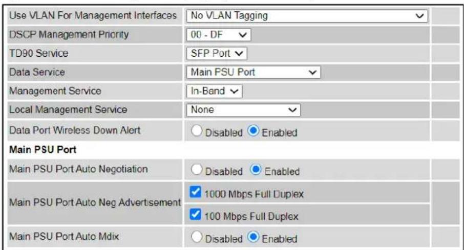
Procedure:
1 Review and update the attributes: IP Interface (Table 177); Main PSU or Aux Port (Table 178); Bridging (Table 180).
2 To save changes, click Submit Updated System Configuration. The system may reboot.
3 If Main PSU Port is selected for Data Service only (and not for Management Service), connect management PC to the port (Aux or SFP) that was selected for Management or Local Management Service
4 If IP Address, Subnet Mask or Gateway IP Address have been changed, reconfigure the local management PC to use an IP address that is valid for the network. Refer to Configuring the management PC on page 6-4.
5 If IP Address has been changed, use the new IP address to log into the unit.
Table 177 IP interface attributes
| Attribute | Meaning |
| IP Version | Defined in Table 166. |
| IPv4 Address | |
| Subnet Mask | |
| Gateway IP Address | |
| IPv6 Address | |
| IPv6 Prefix Length | |
| IPv6 Gateway Address | |
| IPv6 Auto Configured Link Local Address | |
| DNS Resolver | |
| DNS Primary Server | |
| DNS Server 1 Internet Address | |
| DNS Server 1 Port Number | |
| DNS Server 2 Internet Address | |
| DNS Server 2 Port Number | |
| Use VLAN For Management Interfaces | |
| VLAN Management VID | |
| VLAN Management Priority | |
| DSCP Management Priority | |
| TD90 Service | Defined in Table 166. For more help, see Ethernet port allocation on page 3-48. |
| Data Service | |
| Management Service | |
| Local Management Service | |
| Data Port Wireless Down Alert | Disabled: The data Ethernet link will not be dropped when the wireless link drops. Enabled: The Data Ethernet link will be dropped briefly when the wireless link drops. This signals to the connected network equipment that this link is no longer available. Connected Ethernet switches can be configured to forward Ethernet frames on an alternative path identified using the Spanning Tree Protocol (STP). |
| Management Port Wireless Down Alert | Only displayed when an Out-of-Band Port is selected for Management Service. Disabled: The management Ethernet link will not be dropped when the wireless link drops. Enabled: The management Ethernet link will be dropped briefly when the wireless link drops. This signals to the connected network equipment that this link is no longer available. Connected Ethernet switches can be configured to forward Ethernet frames on an alternative path identified using the Spanning Tree Protocol (STP). |
| Management Network Access Enabled | Only displayed when one of the Port selection attributes (Main PSU, Aux or SFP) is set to Out-of-Band Management Service. Yes: The local out-of-band management interface can be used to access the remote management network. No: The local out-of-band management interface cannot be used to access the remote management network. |
Table 178 Main PSU Port and Aux Port attributes
| Attribute | Meaning |
| Auto Negotiation | Disabled:Configuration of the Ethernet interface is forced. Enabled:Configuration of the Ethernet interface is automatically negotiated (default). This is the preferred setting. Use the same setting for the Ethernet link partner. |
| Auto Neg Advertisement | Only displayed when Auto Negotiation is set to Enabled. The data rate that the auto-negotiation mechanism will advertise as available on the Ethernet interface (1000 Mbps or 100 Mbps Full Duplex). Select a data rate that is within the capability of the Ethernet link partner. Use the same setting for the Ethernet link partner. |
| Forced Configuration | Only displayed when Auto Negotiation is set to Disabled. This forces the speed and duplex setting of the Ethernet interface. Over-the-air throughput will be capped to the rate of the Ethernet interface at the receiving end of the link. Select a data rate that is within the capability of the link partner. Use the same setting at both ends. |
| Auto Mdix | Disabled: The Auto Medium Dependent Interface (MDI)/Medium Dependent Interface Crossover (MDIX) capability is disabled. Enabled: The Auto Medium Dependent Interface (MDI)/Medium Dependent Interface Crossover (MDIX) capability is enabled. |
| Power Over Ethernet Output | Aux port only. Disabled: The ODU does not supply power to the auxiliary device. Enabled: The ODU supplies power to the auxiliary device. |
Table 179 SFP Port (connected with copper module) attributes
| Attribute | Meaning |
| SFP Port Auto Negotiation | Disabled: Configuration of the Ethernet interface is forced. This is to be used as a last resort only if auto-negotiation fails. Enabled: Configuration of the Ethernet interface is automatically negotiated (default). This is the preferred setting. |
| SFP Port Auto Neg Advertisement | Only displayed when SFP Port Auto Negotiation is set to Enabled and SFP port is connected with copper module. The data rate that the auto-negotiation mechanism will advertise as available on the Ethernet interface (1000 Mbps or 100 Mbps Full Duplex). Select a data rate that is within the capability of the Ethernet link partner. Use the same setting for the Ethernet link partner. |
| Forced Configuration | Only displayed when SFP Port Auto Negotiation is set to Disabled and SFP port is connected with copper module. This forces the speed and duplex setting of the Ethernet interface. Over-the-air throughput will be capped to the rate of the Ethernet interface at the receiving end of the link. Select a data rate that is within the capability of the Ethernet link partner. Use the same setting for the Ethernet link partner. |
| Auto Mdix | Only displayed when SFP port is connected with copper module. Disabled: The Auto Medium Dependent Interface (MDI)/Medium Dependent Interface Crossover (MDIX) capability is disabled. Enabled: The Auto Medium Dependent Interface (MDI)/Medium Dependent Interface Crossover (MDIX) capability is enabled. |
Table 180 Bridging attributes
| Attribute | Meaning |
| Data Port | Controls whether the bridge tunnels or discards Layer 2 pause frames arriving at the Data port. Such frames are identified by the destination MAC Address being equal to 01-80-C2-00-00-01. |
| Pause | |
| Frames | |
| MAC Filtering | Enabled: The embedded Ethernet switch learns the location of end stations in networks at the wired or wireless ports from the source addresses in received Ethernet frames. The agent filters transmitted Ethernet frames with a unicast destination address to ensure that the frame is transmitted at the wired or wireless port associated with the learned address. If the destination address is broadcast, multicast of unknown unicast, then Ethernet traffic is flooded to all wired and wireless ports in the relevant service. |
| Disabled: The embedded Ethernet switch does not learn the location of end stations, and transmitted frames are always flooded to all wired and wireless ports in the relevant service. | |
 Note In the Local Management Service, Ethernet frames are not transmitted at the wireless port. Note In the Local Management Service, Ethernet frames are not transmitted at the wireless port. |
Table 181 Synchronous Ethernet attributes
| Attribute | Meaning |
| Sync E Tracking | Disabled: The synchronous Ethernet feature is disabled. Synchronization Status Messages received at the Main PSU port will be discarded. Enabled: The synchronous Ethernet feature is enabled. |
| Sync E Equipment Clock | EEC-Option 1: Select this option if the equipment is operating in a 2048 kbit/s synchronisation hierarchy (ITU-T G.813 Option 1) EEC-Option 2: Select this option if the equipment is operating in a 1544 kbit/s synchronisation hierarchy (Type IV clock from ITU-T G.812) |
| Sync E Slave Port | This control configures either the Main PSU Port or the SFP Port as a candidate for selection as a Sync E Slave port. Only ports that are allocated to one of the standard services (Data Service, Management Service, Local Management Service) are offered as options here. |
| Main PSU Port QL Rx Overwrite | This control provides the facility to overwrite the Quality Level (QL) of received Synchronisation Status Messages (SSM). It may be useful in a test environment, or for interworking with equipment that does not generate SSMs. Disabled: The recommended setting, the QL of received SSMs is unmodified. “QL-PRC” or “QL-SSU A / QL-TNC” or “QL-SSU B” or “QL-EEC1 / QL-SEC” or “QL-DNU / QL-DUS”: The overwritten value of the QL. Where two QLs are given, the QL used is dependent upon the setting of “Sync E Equipment Clock” type. |
| SFP Port QL Rx Overwrite | This control provides the facility to overwrite the Quality Level (QL) of Synchronisation Status Messages (SSM) received at the SFP port. It may be useful in a test environment, or for interworking with equipment that does not generate SSMs. Disabled: The recommended setting, the QL of received SSMs is unmodified. “QL-PRC” or “QL-SSU A / QL-TNC” or “QL-SSU B” or “QL-EEC1 / QL-SEC” or “QL-DNU / QL-DUS”: The overwritten value of the QL. Where two QLs are given, the QL used is dependent upon the setting of “Sync E Equipment Clock” type. This control is hidden if Sync E Slave Port is set to Main PSU Port. |
| Main PSU Port SSM Tx | Disabled: SSMs are not transmitted from the Main PSU port. Disabling SSMs may be useful in a test environment. Enabled: SSMs are transmitted from the Main PSU port (normal operation) |
| Aux Port SSM Tx | Disabled: SSMs are not transmitted from the Aux Port. Disabling SSMs may be useful in a test environment. Enabled: SSMs are transmitted from the Aux Port (normal operation) |
| SFP Port SSM Tx | Disabled: SSMs are not transmitted from the SFP port. Disabling SSMs may be useful in a test environment. Enabled: SSMs are transmitted from the SFP port (normal operation) |
Table 182 IEEE 1588 attributes
| Attribute | Meaning |
| Transparent Clock | Disabled: The Transparent Clock function is disabled. IEEE 1588-2008 event frames will be forwarded, but residence time corrections will not be made. Enabled: The Transparent Clock function is enabled. Residence time corrections will be made to IEEE 1588-2008 event frames. |
| Transparent Clock Port | This specifies the transparent clock source port. It can be Main PSU, Aux Port or SFP Fiber. Only the ports allocated for the Data service are available for selection. |
| Transparent Clock VLAN | All: The recommended setting. Residence time corrections will be made to all IEEE 1588-2008 event frames, regardless of any VLAN encapsulation.S-Tagged: Residence time corrections are only made to event frames tagged with a service tag equal to “Transparent Clock VID”.C-Tagged: Residence time corrections are only made to event frames double tagged and with a customer tag equal to “Transparent Clock VID”. |
| Transparent Clock VID | The VLAN Identifier (VID) used with “Transparent Clock VLAN” to restrict residence time corrections to IEEE 1588-2008 event frames in a specific VLAN. |
QoS Configuration page
Menu option: System > Configuration > QoS Configuration (Figure 159 or Figure 160 or Figure 161). Use this page to control the quality of service configuration. Classification may be based on fields in the Ethernet header (Layer 2) or in the network header (Layer 3). The unit recognizes two network layer protocols: IP and MPLS.

Note In PTP topology, eight QoS levels (Q0 to Q7) are supported, while in HCMP topology, only four QoS levels (Q0 to Q3) are supported for each wireless link.
Figure 159 QoS Configuration page (Ethernet)
QoS Configuration
This page controls the quality of service configuration.
Layer 2 Control Protocols
| Protocol | Queue |
| Bridge | Q7 √ |
| MRP | Q7 √ |
| CFM | Q7 √ |
| R-APS | Q7 √ |
| EAPS | Q7 √ |
| PPPoE Discovery LCP | Q7 √ |
Data Priority Scheme
| Data Priority Scheme | ● Ethernet ○ IP/MPLS |
Ethernet Priority
| Priority | Queue |
| P0 | Q1 √ |
| P1 | Q0 √ |
| P2 | Q2 √ |
| P3 | Q3 √ |
| P4 | Q4 √ |
| P5 | Q5 √ |
| P6 | Q6 √ |
| P7 | Q7 √ |
| Untagged | Q1 √ |
Reset Default Priority Mappings
Submit Updated Configuration
Reset Form
Figure 160 QoS Configuration page (IP/MPLS), Extract
| Data Priority Scheme | |||||||
| Data Priority Scheme | ○ Ethernet ● IP/MPLS | ||||||
| Unknown Network Layer Protocol | |||||||
| Unknown Protocol | Q1 | ||||||
| IP DSCP | |||||||
| DSCP | Queue | DSCP | Queue | DSCP | Queue | DSCP | Queue |
| 00 - DF | Q1 | 16 - CS2 | Q3 | 32 - CS4 | Q4 | 48 - CS6 | Q7 |
| 01 | Q1 | 17 | Q1 | 33 | Q1 | 49 | Q1 |
| 02 | Q1 | 18 - AF21 | Q3 | 34 - AF41 | Q4 | 50 | Q1 |
| 03 | Q1 | 19 | Q1 | 35 | Q1 | 51 | Q1 |
| 04 | Q1 | 20 - AF22 | Q3 | 36 - AF42 | Q4 | 52 | Q1 |
| 05 | Q1 | 21 | Q1 | 37 | Q1 | 53 | Q1 |
| 06 | Q1 | 22 - AF23 | Q3 | 38 - AF43 | Q4 | 54 | Q1 |
| 07 | Q1 | 23 | Q1 | 39 | Q1 | 55 | Q1 |
| 08 - CS1 | Q0 | 24 - CS3 | Q3 | 40 - CS5 | Q5 | 56 - CS7 | Q1 |
| 09 | Q1 | 25 | Q1 | 41 | Q1 | 57 | Q1 |
| 10 - AF11 | Q2 | 26 - AF31 | Q3 | 42 | Q1 | 58 | Q1 |
| 11 | Q1 | 27 | Q1 | 43 | Q1 | 59 | Q1 |
| 12 - AF12 | Q2 | 28 - AF32 | Q3 | 44 - VA | Q6 | 60 | Q1 |
| 13 | Q1 | 29 | Q1 | 45 | Q1 | 61 | Q1 |
| 14 - AF13 | Q2 | 30 - AF33 | Q3 | 46 - EF | Q6 | 62 | Q1 |
| 15 | Q1 | 31 | Q1 | ||||
Figure 161 QoS Configuration page showing Out-of-Band Management
QoS Configuration
This page controls the quality of service configuration.
Layer 2 Control Protocols
| Protocol | Queue |
| Bridge | Q7 √ |
| MRP | Q7 √ |
| CFM | Q7 √ |
| R-APS | Q7 √ |
| EAPS | Q7 √ |
| PPPoE Discovery LCP | Q7 √ |
Data Priority Scheme
| Data Priority Scheme | ● Ethernet ○ IP/MPLS |
Ethernet Priority
| Priority | Queue |
| P0 | Q1 √ |
| P1 | Q0 √ |
| P2 | Q2 √ |
| P3 | Q3 √ |
| P4 | Q4 √ |
| P5 | Q5 √ |
| P6 | Q6 √ |
| P7 | Q7 √ |
| Untagged | Q1 √ |
Out-of-Band Management Service
Traffic Priority
| Queue | Q7 | |
| Reset Default Priority Mappings | ||
| Submit Updated Configuration | Reset Form | |
Procedures:
• Review and update the attributes (Table 183 and Table 184).
• To use IEEE 802.1Q classification rules, click Reset Default Priority Mappings.
• To save changes, click: Submit Updated Configuration.

Note Priority mapping must be configured the same at both Master and Slave units on the wireless link.
Table 183 QoS Configuration attributes - Data Service
| Attribute | Meaning |
| Bridge | The classification of each layer 2 control protocol (L2CP) to an egress queue at the wireless port. |
| MRP | |
| CFM | |
| R-APS | |
| EAPS | |
| PPPoE Discovery LCP | |
| Data Priority Scheme | Ethernet: Classification is based on fields in the Ethernet header (Layer 2).IP/MPLS: Classification is based on fields in the network header (Layer 3). IP includes IPv4 and IPv6. |
| Unknown Protocol | Only displayed when Priority Scheme is IP/MPLS.The classification of unknown network protocols (that is, not IP or MPLS) to an egress queue at the wireless port. |
| Ethernet Priority | Ethernet priority mapping to Queue |
Table 184 QoS Configuration attributes -Out-of-Band Management Service
| Attribute | Meaning |
| Queue | Only displayed when one ODU port is allocated to Out-of-Band Management (Configuring port allocations on page 6-25).The classification of out-of-band management traffic to an egress queue at the wireless port. |
SFP Configuration page
Menu option: System > Configuration > SFP Configuration.
This page is only available when the ODU detects an optical (Figure 162) or copper (Figure 163) SFP module in the SFP port. Use it to configure the way in which the unit connects to the network via the SFP interface.
Figure 162 SFP Configuration page (optical SFP module)
SFP Configuration
This page controls the SFP configuration of the PTP wireless unit.
| Attributes | Value | Units |
| SFP Port Auto Negotiation | Disabled Enabled | |
| Sfp Vendor Name | JDSU | |
| Sfp Vendor OUI | 00:01:9c | |
| Sfp Part Number | PLRXPL-VI-S24-22 | |
| Sfp Revision Level | 1 | |
| Sfp Laser Wavelength | 850 | |
| Sfp Serial Number | CA51QA098 | |
| Sfp Date Code | 101214 |
Figure 163 SFP Configuration page (copper SFP module)
SFP Configuration
This page controls the SFP configuration of the PTP wireless unit.
| Attributes | Value | Units |
| SFP Port Auto Negotiation | ○ Disabled ● Enabled | |
| SFP Port Auto Neg Advertisement | ☑ 1000 Mbps Full Duplex | |
| ☑ 100 Mbps Full Duplex | ||
| SFP Port Auto Mdix | ○ Disabled ● Enabled | |
| Sfp Vendor Name | FINISAR CORP. | |
| Sfp Vendor OUI | 00:90:65 | |
| Sfp Part Number | FCLF8522P2BTL | |
| Sfp Revision Level | A | |
| Sfp Serial Number | PM54X88 | |
| Sfp Date Code | 120205 | |
| Submit Updated System Configuration Reset Form | ||
Procedure (only applies when copper SFP module is installed):
- Update the attributes
- When optical SFP module is installed (Table 187).
- When copper SFP module is installed (Table 186)
• To save changes, click Submit Updated System Configuration.
Table 185 SFP Configuration (Optical module) attributes
| Attribute | Meaning |
| SFP Port Auto Negotiation | Disabled: Configuration of the Ethernet interface is forced. This is to be used as a last resort only if auto-negotiation fails. Enabled: Configuration of the Ethernet interface is automatically negotiated (default). This is the preferred setting. |
Table 186 SFP Configuration (copper SFP module) attributes
| Attribute | Meaning |
| SFP Port Auto Negotiation | Disabled: Configuration of the fiber interface is forced. This is to be used as a last resort only if auto-negotiation fails. Enabled: Configuration of the fiber interface is automatically negotiated (default). This is the preferred setting. |
| SFP Port Auto Neg Advertisement | Only displayed when SFP Port Auto Negotiation is set to Enabled. The data rate that the auto-negotiation mechanism will advertise as available on the Ethernet interface (1000 Mbps or 100 Mbps Full Duplex). Select a data rate that is within the capability of the Ethernet link partner. Use the same setting for the Ethernet link partner. |
| Forced Configuration | Only displayed when SFP Port Auto Negotiation is set to Disabled. This forces the speed and duplex setting of the Ethernet interface. Over-the-air throughput will be capped to the rate of the Ethernet interface at the receiving end of the link. Select a data rate that is within the capability of the Ethernet link partner. Use the same setting for the Ethernet link partner. |
| Auto Mdix | Disabled: The Auto Medium Dependent Interface (MDI)/Medium Dependent Interface Crossover (MDIX) capability is disabled. Enabled: The Auto Medium Dependent Interface (MDI)/Medium Dependent Interface Crossover (MDIX) capability is enabled. |
Authorization Control page
Menu option: System > Configuration > Authorization Control (Figure 164).
Authorization control is used when Access Method is configured to Group Access, and Encryption Algorithm is configured to TLS-RSA. In the HCMP topology, Group Access is the only Access Method supported. The Authorization Control page is hidden if it is not applicable.
When Authorization Method is configured to Whitelist, the ODU will connect only if the authenticated MAC address of the remote unit is in the list of authorized ODUs. With the Blacklist option, the ODU will always connect unless the authenticated MAC address has been added to a list of unauthorized ODUs.
The Authorization Control page allows up to 32 MAC addresses to be entered.
Authorization Control does not require an AES license.
Procedure:
- Select Whitelist or Blacklist
- Update the MAC Addresses
• To save changes, click Submit Configuration.

Note The associated wireless link is automatically dropped if the MAC address of an already-connected ODU is added to the Blacklist or removed from the Whitelist.
Figure 164 Authorization Control page
| Authorization Method Whitelist data entry | ||
| Entry | MAC Address | Enabled |
| 1 | 00:04:56: 58 : 00 : c0 | ✓ |
| 2 | 00:04:56: 58 : 00 : b6 | ✓ |
| 3 | 00:04:56: 58 : 00 : 5b | ✓ |
| 4 | 00:04:56: 58 : 00 : 67 | ✓ |
| 5 | 00:04:56: 58 : 00 : 6c | ✓ |
| 6 | 00:04:56: 58 : 00 : 85 | ✓ |
| 7 | 00:04:56: 58 : 00 : c4 | ✓ |
| 8 | 00:04:56: 58 : 01 : 43 | ✓ |
| 9 | 00:04:56: 00 : 00 : 00 | ☐ |
| 10 | 00:04:56: 00 : 00 : 00 | ☐ |
| 29 | 00:04:56: 00 : 00 : 00 | ☐ |
| 30 | 00:04:56: 00 : 00 : 00 | ☐ |
| 31 | 00:04:56: 00 : 00 : 00 | ☐ |
| 32 | 00:04:56: 00 : 00 : 00 | ☐ |
| Enable All Disable All Clear Configuration | ||
| Submit Configuration Reset Form | ||
Save and Restore Configuration page
Menu option: System > Configuration > Save And Restore (Figure 165).
Use the Save & Restore Configuration page to take a snapshot of the latest system configuration as a backup. The file can then be used to restore this unit to a known state, or to configure a replacement unit to the same state. The configuration values are encrypted for security.
Figure 165 Save & Restore Configuration page
Save & Restore Configuration
Save Configuration
A snapshot of the latest system configuration can be saved to a file as a backup. The file can then be used to restore this unit to a known state, or configure a replacement unit to the same state. The configuration values are encrypted for security.
Click the button below to save the configuration file
Save Configuration File
Restore Configuration
Note: this utility will only restore configuration files that were saved using software version 999.00.
Please select the configuration file to restore
Browse_ No file selected.
Restore Configuration File and Reboot
Save the system configuration in the following situations:
• After a new unit has been fully configured as described in this chapter.
• After any change has been made to the configuration.
- Before upgrading the unit to a new firmware version.
• After upgrading the unit to a new firmware version.


Note The restore is only guaranteed to work if the installed firmware version has not been changed since the configuration file was saved. This is why the configuration should always be saved immediately after upgrading the firmware version.
Note The license key is restored automatically if the configuration file is saved and then loaded on the same unit. However, the license key is not restored if the configuration file is loaded on a different unit. Before restoring configuration to a different PTP 700 unit, ensure that a valid license key is installed (with optional capabilities enabled where appropriate).
Most of the configuration can be restored from the backup. However, certain attributes that were part of the configuration are not saved or restored automatically. Use the web interface to reconfigure the following attributes:
- Usernames, passwords and roles for the web-based interface.
- Key of Keys
- Entropy
- HTTPS Private Key
- HTTPS Public Key Certificate
- HTTP Access Enabled
- HTTPS Access Enabled
- Telnet Access Enabled
- HTTP Port Number
- HTTPS Port Number
- Telnet Port Number
- Encryption Algorithm
- Encryption Key
- User-supplied Device Private Key
• User-supplied Device Public Key Certificate - User-supplied Root CA Certificate
• SNMP Control Of HTTP And Telnet
• SNMP Control of Passwords - Unit Name
Procedures:
- To save the configuration:
- Click Save Configuration File.
- Save the file. The default filename is in the format MAC-mm-mm-mm_IP-iii-iii-iii-iii.cfg, where mm-mm-mm is MAC address of unit and iii-iii-iii-iii is Internet address of unit.
- To restore the configuration:
- Click Browse and navigate to the PC folder containing the saved configuration file (.cfg).
- Click Restore Configuration File and Reboot.
- Click OK to confirm the restore. The configuration file is uploaded and used to reconfigure the new unit to the same state as the old unit. On completion, the unit reboots.

Note If Identity Based User Accounts is Enabled, the restore action can only be taken by a user with the Security Officer role.
See Creating a user account on page 6-6 to create a new user account for the web-based interface after configuration has been restored.
Reset Configuration page
Menu option: System > Configuration > Reset Configuration. Use this page to reset the ODU configuration to default settings, retaining the most recently entered License Key (Figure 166).
The Reset Configuration page resets the configuration to default settings. After successful execution of Reset Configuration, the ODU reboots and is then accessible via the default IP address (i.e. 169.254.1.1).
Figure 166 Reset Configuration page
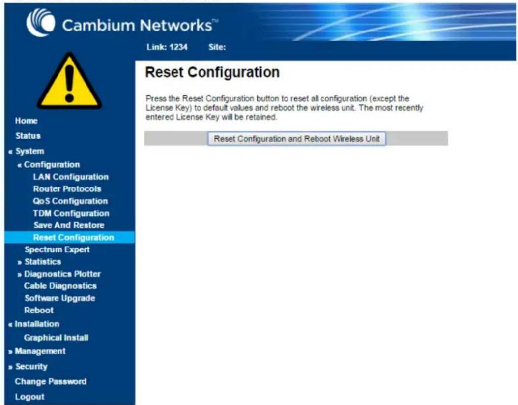
Procedure:
- Click Reset Configuration. The user pop up box is displayed to reconfirm:

- Click OK to restore configuration to the default settings and reboot of unit.
Further reading
| For information about... | Refer to... |
| Erase Configuration | Use this option to erase the entire configuration of the unit. Refer to Resetting all configuration data on page 7-86. |
Software Upgrade page
Menu option: System > Software Upgrade (Figure 167).
Use this page to upgrade the unit to a new version of PTP 700 operational firmware.
Figure 167 Software Upgrade page


natural_image
Pure electrical circuit symbols without any text or labelsAttention Ensure that the correct units are upgraded, as units cannot easily be downgraded afterwards.
Attention Firmware version must be the same at both ends of the link. Limited operation may sometimes be possible with dissimilar firmware versions, but such operation is not supported by Cambium Networks.
Attention If the link is operational, upgrade the remote end of the link first, then upgrade the local end. Otherwise, the remote end may not be accessible.
Note Separate firmware images are provided for PTP 45700 and PTP 78700. Ensure that the firmware image is correct for the hardware platform.
Note See Transition of digital signature algorithms on page 1-78 for details of a transition in digital signatures of replacement firmware.
Preparation:
Obtain the latest firmware from Cambium Support. If this is later than that installed on the PTP 700 unit, perform the procedure below.
Procedure:
1 Save the system configuration; see Save and Restore Configuration page on page 6-77.
2 On the Software Upgrade page, click Browse. Navigate to the folder containing the downloaded firmware image with file extension DLD3, and click Open.
3 Click Upload Software Image. The Software Upgrade Confirmation page is displayed:
Software Upgrade: Are You Sure?
The tables below compare the image stored in the primary software bank with the image that has just been downloaded. Press the "Program Software Image into Non-Volatile Memory" button to accept the software upgrade.
Current software image description
© 2000-2015 Cambium Networks Limited. All rights reserved. Software Version: 45700-00-04
Uploaded software image description
© 2000-2015 Cambium Networks Limited. All rights reserved. Software Version: 45700-00-05
Program Software Image into Non-Volatile Memory

Back
4 Click Program Software Image into Non-Volatile Memory. The Progress Tracker page is displayed. On completion, the Software Upgrade Complete page is displayed:
Software Upgrade Complete
The software upgrade was completed Successfully. To complete the upgrade a system reboot is required. Please use the 'Reboot Wireless Unit' button below to reboot the unit.
Current software image description
© 2000-2015 Cambium Networks Limited. All rights reserved. Software Version: 45700-00-05
Reboot Wireless Unit

Back
5 Click Reboot Wireless Unit, then click OK to confirm. The unit reboots with the new firmware installed.
6 Save the post-upgrade system configuration; see Save and Restore Configuration page on page 6-77.

Note The unit will not upload FIPS versions of the firmware unless the unit has the AES encryption and FIPS licenses installed.

Note Users with the Security Officer user role are allowed to upgrade firmware, including swapping between standard (non-FIPS) and FIPS versions.
System Administrator users are allowed to upgrade from one standard version to another standard version, or from one FIPS version to another FIPS version, but are not allowed to swap between standard and FIPS versions.
SSPs are automatically zeroized when the ODU is upgraded from a standard version to a FIPS version, or from a FIPS version to a standard version. See Creating a user account on page 6-6 to create a new user account for the web-based interface after SSPs have been zeroized.
Management menu
This section describes how to configure web-based management of the PTP 700 unit.
Web-Based Management page
Menu option: Management > Web (Figure 168).
Use this page to configure web-based management of the unit.
Figure 168 Web-Based Management page


Attention If the HTTP, HTTPS, Telnet and SNMP interfaces are all disabled, then it will be necessary to use the Recovery image to reset IP & Ethernet Configuration back to defaults to re-enable the interfaces.
Note The HTTP and Telnet interfaces should be disabled if the HTTPS interface is configured. (see Planning for HTTPS/TLS operation on page 3-72).
Procedure:
• Review and update the attributes (Table 187).
• To save changes, click Submit Updated Configuration.
Table 187 Web-Based Management attributes
| Attribute | Meaning |
| HTTPS Access Enabled | Only displayed when HTTPS is configured.No: The unit will not respond to any requests on the HTTPS port.Yes: The unit will respond to requests on the HTTPS port. |
| HTTPS Port Number | Only displayed when HTTPS is configured. The port number for HTTPS access. A value of zero means the wireless unit uses the default port. |
| HTTP Access Enabled | No: The unit will not respond to any requests on the HTTP port.Yes: The unit will respond to requests on the HTTP port.Remote management via HTTPS is not affected by this setting. |
| HTTP Port Number | The port number for HTTP access. A value of zero means the wireless unit uses the default port. |
| Telnet Access Enabled | No: The unit will not respond to any requests on the Telnet port.Yes: The unit will respond to requests on the Telnet port. |
| Telnet Port Number | The port number for Telnet access. A value of zero means the wireless unit uses the default port. |
| Access Control | Enables or disables access control to web-based management by Internet Address. |
| Access Control Internet Address 1/2/3 | A list of up to three IPv4 or IPv6 Addresses permitted to perform web-based management.Only displayed when Access Control is set to Enabled. |
| SNMP Control of HTTP And Telnet | Disabled: Neither HTTP nor Telnet can be controlled remotely via SNMP.Enabled: Both HTTP and Telnet can be controlled remotely via SNMP. |
| SNMP Control of Passwords | Enabled: Passwords for identity-based user accounts in the web-based interface can be updated via SNMP. This option can be used together with SNMPv3 to provide a secure means to update passwords from a central network manager.Disabled: Passwords for identity-based user accounts can be updated only via the web-based interface (default). |
| TFTP Client | Disabled: The unit will not respond to any TFTP firmware download requests.Enabled: Firmware can be downloaded via TFTP, as described in Upgrading firmware using TFTP on page 6-155. |
| Instant Messaging Enabled | No: Instant Messaging is Disabled.Yes: Instant Messaging is Enabled. The IM interface is under menu option Management > Instant Messaging. |
| Debug Access Enabled | Yes: Cambium Technical Support is allowed to access the system to investigate faults. |
| Cross Site Request Forgery Protection | Enabled: The system is protected against cross-site request forgery attacks at the web-based interface. |
Local User Accounts page
Menu option: Management > Web > Local User Accounts.
The contents of this page depend upon the setting of Identity Based User Accounts: Disabled (Figure 169) or Enabled (Figure 170).
Use this page to ensure that user access to the web-based management interface is controlled in accordance with the network operator's security policy. The Identity Based User Accounts option allows multiple users (from one to ten) to access the unit with one of four levels of access: Security Officer, System Administrator, Installer and Read Only. If Identity Based User Accounts are Enabled, this procedure may only be performed by a Security Officer.

Note Local User Account Names, Roles and Passwords are sensitive security parameters that can be reset from the Zeroize SSPs page (Zeroize SSPs page) on page 6-136.
Figure 169 Local User Accounts page (Identity Based User Accounts disabled)


Note Identity Based User Accounts is automatically set to Enabled in the FIPS 140-3 secure mode.
Figure 170 Local User Accounts page (Identity Based User Accounts enabled)
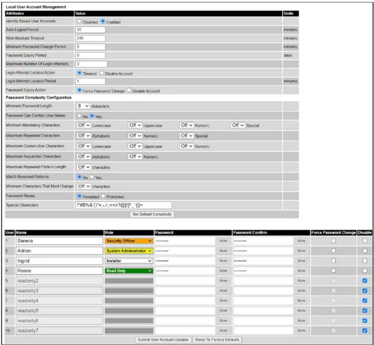
Procedure:
-
Choose whether to set Identity Based User Accounts to Disabled or Enabled.
• Review and update the Local User Account Management attributes (Table 188).
• If Identity Based User Accounts is set to Enabled: -
Review and update the Password Complexity Configuration attributes (Table 189). To return to default values, click Set Default Complexity.
• Review and update up to 10 identity-based user accounts (Table 190).
• If any attributes have been updated, click Submit User Account Updates.
Table 188 Local User Account Management attributes
| Attribute | Meaning |
| Identity Based User Accounts | Disabled: Access to the web interface is controlled by a single system administration password. Enabled: Up to 10 users may access the unit. |
| Auto Logout Period | The time without user activity that elapses before a user is automatically logged out (minutes). A value of zero disables this feature. |
| Web Absolute Timeout | The time that elapses before a user is automatically logged out (minutes). |
| Minimum Password Change Period | The minimum time that elapses before a user is allowed to change a password (minutes). A value of zero disables this feature. |
| Password Expiry Period | The time that elapses before a password expires (days). A value of zero disables this feature. |
| Maximum Number of Login Attempts | The maximum number of login attempts (with incorrect password) that are allowed before a user is locked out. Also, the maximum number of password change attempts before a user is locked out. |
| Login Attempt Lockout Action | Only displayed when Identity Based User Accounts is Enabled. Timeout: When a user is locked out, the user is allowed to log in again after a specified period. Disabled: When a user is locked out, the user is disabled. |
| Login Attempt Lockout Period | Only displayed when Identity Based User Accounts is Disabled. The time that elapses before a locked out user is allowed to log in again (minutes). Only displayed when Login Attempt Lockout Action is set to Timeout. |
| Password Expiry Action | Only displayed when Identity Based User Accounts is Enabled. The action to be taken by the PTP 700 when a password expires. |
Table 189 Password Complexity Configuration attributes
| Attribute | Meaning |
| Minimum Password Length | 8..31: The minimum number of characters required in passwords.15..31: The minimum number of characters required in passwords in FIPS Approved mode. |
| Password Can Contain User Name | No: Passwords must not contain the user name.Yes: Passwords may contain the user name. |
| Minimum Mandatory Characters | The minimum number of lowercase, uppercase, numeric and special characters required in passwords.For example, if all values are set to 2, then FredBloggs will be rejected, but FredBloggs(25) will be accepted. |
| Maximum Repeated Characters | The maximum number of consecutive repeated alphabetic, numeric and special characters permitted in passwords.For example, if all values are set to 2, then aaa, XXX, 999 and will be rejected, but aa, XX, 99 or will be accepted. |
| Maximum Consecutive Characters | The maximum number of consecutive lowercase, uppercase and numeric characters permitted in passwords.For example, if all values are set to 5, then ALFRED, neuman and 834030 will be rejected. |
| Maximum Sequential Characters | The maximum number of alphabetic and numeric characters permitted in passwords.For example, if set to 3, then abcd,WXYZ and 0123 will be rejected, but abc, xyz and 123 will be accepted. |
| Maximum Repeated Pattern Length | The maximum sequence of characters that can be repeated consecutively in passwords.For example, if set to 3, then BlahBlah and 31st31st will be rejected, but TicTicTock and GeeGee will be accepted. Blah-Blah will be accepted because the two sequences are not consecutive. |
| Match Reversed Patterns | No: Reversed patterns are not checked.Yes: Reversed patterns are checked.For example, if Maximum Repeated Pattern Length is set to 3 and Match Reversed Patterns is set to Yes, then AB1221BA will be rejected. |
| Minimum Characters That Must Change | The minimum number of password characters that must change every time a password is updated. |
| Password Reuse | Permitted: A user may reuse a previous password.Prohibited: A user must not reuse a previous password. |
| Special Characters | User defined set of special characters used in password construction. The only characters permitted in a password are: (a-z), (A-Z), (0-9) and any of the special characters entered here. |
Table 190 Identity-based user accounts attributes
| Attribute | Meaning |
| Name | Enter a user name. |
| Role | Select a role from the list: Security Officer, System Administrator, Installer or Read Only. |
| Password | Enter a password for the user. Passwords must comply with the complexity rules (Table 189). |
| Password Confirm | Retype the password to confirm. |
| Force Password Change | Force this user to change their password when they next log on. |
| Disable | Tick the box to disable a user account. |

Note At least one locally-authenticated user must be assigned the Security Officer role.
RADIUS Configuration page
Menu option: Management > Web > Radius Configuration (Figure 171).
Use this page to configure RADIUS authentication. RADIUS authentication is only available when PTP 700 is configured for Identity-based User Accounts and when RADIUS servers are connected to the network.
Figure 171 RADIUS Configuration page
| RADIUS Configuration | ||
| Attributes | Value | Units |
| RADIUS Client | ○Disabled ○Enabled | |
| RADIUS Primary Server | ●Server 1 ○ Server 2 | |
| RADIUS Primary Server Dead Time | 5 | minutes |
| RADIUS Server Retries | 2 | |
| RADIUS Server Timeout | 3 | seconds |
| Authentication Method | ●CHAP ○ MS-CHAP-v2 | |
| Authentication Server 1 | ||
| RADIUS Server Status | server not yet used | |
| RADIUS Server Internet Address | ||
| RADIUS Server Authentication Port | 1812 | |
| RADIUS Server Shared Secret | Enter server shared secret upto 127 alphanumeric, special characters | Show |
| RADIUS Server Shared Secret Confirm | Confirm server shared secret | Show |
| Authentication Server 2 | ||
| RADIUS Server Status | server not yet used | |
| RADIUS Server Internet Address | ||
| RADIUS Server Authentication Port | 1812 | |
| RADIUS Server Shared Secret | Enter server shared secret upto 127 alphanumeric, special characters | Show |
| RADIUS Server Shared Secret Confirm | Confirm server shared secret | Show |
| Submit RADIUS Configuration | ||

Note Only users with Security Officer role are permitted to configure RADIUS authentication.

Note RADIUS is disabled in the FIPS 140-3 Approved Mode.
Procedure:
- Update the attributes (Table 191).
- Click Submit RADIUS Configuration.
Table 191 RADIUS Authentication attributes
| Attribute | Meaning |
| RADIUS Client Enabled | Enabled: PTP 700 users may be authenticated via the RADIUS servers. Disabled: RADIUS authentication is not used. This may only be selected if at least one user with Security Officer privileges exists. |
| RADIUS Primary Server | Specifies the primary server, determining the order in which the servers are tried. |
| RADIUS Primary Server Dead Time | Time (in minutes) to hold off trying to communicate with a previously unavailable RADIUS server. Setting the value to zero disables the timer. |
| RADIUS Server Retries | Number of times the PTP 700 will retry after a RADIUS server fails to respond to an initial request. |
| RADIUS Server Timeout | Time (in seconds) the PTP 700 will wait for a response from a RADIUS server. |
| Authentication Method | Method used by RADIUS to authenticate users. |
| Authentication Server 1 and 2: | |
| RADIUS Server Status | The status of the RADIUS server. This contains the time of the last test and an indication of success or failure.If the Authentication Server attributes are incorrect, the displayed status is “server config not valid”. |
| RADIUS Server Internet Address | FQDN, IPv4 or IPv6 address of the RADIUS server. |
| RADIUS Server Authentication Port | Network port used by RADIUS server for authentication services. |
| RADIUS Server Shared Secret | Shared secret used in RADIUS server communications. May contain alphabetic, numeric, special characters or spaces, but not extended unicode characters. The maximum length is 127 characters. |
| RADIUS Server Shared Secret Confirm | Shared secret confirmation. |
SSO Configuration page
Menu option: Management > Web > SSO Configuration (Figure 172).
Use this page to configure Single Sign On (SSO) authentication. SSO authentication is only available when PTP 700 is configured for Identity-based User Accounts and when a suitable Identity Provider (IdP) is connected to the network.
Figure 172 SSO Configuration page
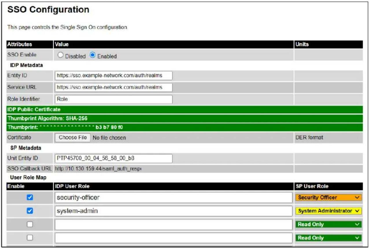

Note Only users with Security Officer role are permitted to configure SSO authentication.
Procedure:
- Update the attributes (Table 192).
- Click Submit.
Table 192 SSO Authentication attributes
| Attribute | Meaning |
| SSO Enable | Disabled: Disables SSO authentication feature. Enabled: Enables SSO authentication feature. |
| IDP Metadata | |
| Entity ID | This is the Entity ID of the Identity Provider (IdP) server. It must match the issuer of the SAML Response and the containing Assertion. |
| Service URL | Specifies the destination within the SAML Request sent to the IdP. |
| Role Identifier | Identifies the attribute in the SAML Response that contains the user role information sent by the IdP server. |
| Certificate | Upload or specify the certificate provided by the Identity Provider (IdP) for secure communication. |
| SP Metadata | |
| Unit Entity ID | Automatically generated Entity ID for the Service Provider (SP). Can be edited if necessary. |
| SSO Callback URL | URL to which the SAML Response must be sent back by the IdP. |
| User Role Map | |
| Enable | Enables this specific configuration row. |
| IDP User Role | Specifies the user role that must match the role in Assertions contained in the SAML Response sent by the IdP server. |
| SP User Role | Specifies the local user role to which the IdP User Role should be mapped during authentication. |
Webpage Properties page
Menu option: Management > Web > Web Properties (Figure 173).
Use this page to control the display of the web interface.
Figure 173 Webpage Properties page

Procedure:
- Update the attributes (Table 193).
- Click Apply Properties.
Table 193 Webpage Properties attributes
| Attribute | Meaning | |
| Web Properties | Disable Spectrum Expert (use old Spectrum Management):If not ticked (the default setting), the System Menu includes Spectrum Expert (not Spectrum Management).If ticked, the System Menu includes Spectrum Management (not Spectrum Expert).Configure Link Registration Timeout Control:If not ticked (the default setting), the Link Registration Timeout and Link Registration Timeout Period controls are hidden.If ticked, the Wireless Configuration page (Wireless Configuration page on page 6-28) includes the Link Registration Timeout and Link Registration Timeout Period controls. | |
| Distance Units | Metric: Distances are displayed in kilometers or meters.Imperial: Distances are displayed in miles or feet. | |
| Use Long Integer Comma Formatting | Disabled: Long integers are displayed thus: 1234567.Enabled: Long integers are displayed thus: 1,234,567. | |
| Transmitter Mute Control | Disabled: Hides the Enable Transmission attribute.Enabled: Shows the Enable Transmission attribute (System Configuration page on page 6-56). | |
| Transmitter Channels Control | Disabled: Hides the Transmitter Channels attribute. Enabled: Shows the Transmitter Channels attribute (Wireless Configuration page on page 6-28 and System Configuration page on page 6-56). | |
| MAC Filtering Control | Disabled: Hides the MAC Filtering attribute. Enabled: Shows the MAC Filtering attribute in the LAN Configuration page. See LAN Configuration page on page 6-60. | |
 | Note Review MAC Filtering on page 1-47 before enabling the MAC Filtering control. | |
| Send HTTPS Close Notify Alerts | Only displayed when HTTPS is configured. Controls whether or not the HTTPS server sends TLS Close Notify Alerts before it shuts down each socket. Disabled: TLS Close Notify Alerts are not sent before closing each socket. This is the default because these alerts can cause problems with some browsers (e.g. Internet Explorer) Enabled: TLS Close Notify Alerts are sent before closing each socket. | |
| Browser Title | By default, web browser tab titles display PTP 700 model, page title and IP address in the following format: “Cambium PTP 45700 - “ &{name & “ (IP = ” & ipAddress &”)” To change the default text, enter simple text and optional variables (prefixed with a $ character). The full list of variables is in Table 194. | |
Table 194 Browser Title attribute variables
| Variable | Meaning |
| groupID | |
| ipAddress | IP Address currently used to identify the ODU, either IPv4 or IPv6 Address, depending upon the setting of IP Address Label in the System Configuration page (Table 176):IPv4: ipAddress =ipv4AddressIPv6: ipAddress =ipv6Address (if not blank) or ipv6LinkLocalAddress |
| ipv4Address | IPv4 Address of the ODU, as set in the LAN Configuration page (Table 177). |
| ipv6Address | IPv6 Address of the ODU, as set in the LAN Configuration page (Table 177). |
| ipv6LinkLocalAddress | IPv6 Auto Configured Link Local Address of the ODU. This cannot be updated, but it can be viewed in the LAN Configuration page (Table 177). |
| /linkName | Link Name, as set in the System Configuration page (Table 176). |
| /masterSlaveMode | Master Slave Mode, as set in the Step 2: Wireless Configuration page (Table 168). |
| /productName | The product variant, for example Cambium PTP 700. Not updateable. |
| /captionName | Name of the page currently being browsed. |
| /protectionMode | Role and status of the ODU in a Hot Standby link. For example, “Primary Master, Standby”. |
| /siteName | Site Name, as set in the System Configuration page (Table 176). |
| /sysName | Sys Name for this SNMP managed node, as set in the Step 2: SNMP MIB-II System Objects page (Table 201). |
| /unitName | |
Email Configuration page
Menu option: Management > Email (Figure 174). Use this page to enable the PTP 700 to generate Simple Mail Transfer Protocol (SMTP) email messages to notify the system administrator when certain events occur.
Figure 174 Email Configuration page
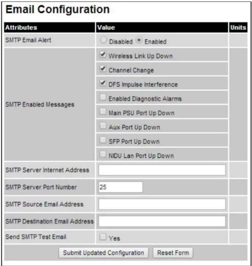
Procedure:
- Update the attributes (Table 195).
- Click Submit Updated Configuration. The Configuration Change Reboot dialog is displayed.
- Click Reboot Wireless Unit and click OK. The reboot progress message is displayed. On completion, the unit restarts.
Table 195 Email Configuration attributes
| Attribute | Meaning |
| SMTP Email Alert | Controls the activation of the SMTP client. |
| SMTP Enabled Messages | The SMTP Enabled Messages attribute controls which email alerts the unit will send. |
| SMTP Server Internet Address | The FQDN, IPv4 or IPv6 Address of the networked SMTP server. |
| SMTP Server Port Number | The SMTP Port Number is the port number used by the networked SMTP server. By convention the default value for the port number is 25. |
| SMTP Source Email Address | The email address used by the PTP 700 Series to log into the SMTP server. This must be a valid email address that will be accepted by your SMTP Server. |
| SMTP Destination Email Address | The email address to which the PTP 700 Series will send the alert messages. |
| Send SMTP Test Email | Generate and send an email in order to test the SMTP settings. The tick box will self-clear when Submit is clicked. |
Instant Messaging page
Menu option: Management > Instant Messaging (Figure 175).
Use this page to send text-based messages to an operator at the remote end of the wireless link. Type the message (maximum 180 characters) in the edit box and press the Send button. The message is added to the message history when it has been received at the remote end of the link.
Instant Messaging is available in PTP and HCMP topologies. At an HCMP Master ODU, select the destination Slave ODU from a list of connected ODUs. HCMP Slaves can exchange messages with the associated Master ODU through this service but HCMP Slaves cannot message each other.
The ODU provides an alert in the Status Bar (Figure 176) if messages are received when the Instant Messaging page is not displayed.

Note Instant Messaging is disabled by default. Enable Instant Messaging using the Web-Based Management page.
Figure 175 Instant Messaging page

Figure 176 Unread messages

Diagnostic Alarms page
Menu option: Management > Diagnostic Alarms (Figure 177).
Use this page to select which diagnostic alarms will be notified to the system administrator.
Figure 177 Diagnostic Alarms page
| Diagnostic Alarms | ||
| Attributes | Value | Units |
| Enabled Diagnostic Alarms | ✓ Regulatory Band | |
| ✓ Install Status | ||
| ✓ Install Arm State | ||
| ✓ Unit Out Of Calibration | ||
| ✓ Maximum Link Range Exceeded | ||
| ✓ Incompatible Regulatory Bands | ||
| ✓ Incompatible Master And Slave | ||
| ✓ Port State | ||
| ✓ No Wireless Channel Available | ||
| ✓ SNTP Synchronization Failed | ||
| ✓ Wireless Link Disabled Warning | ||
| ✓ TDD Synchronization Alarm | ||
| ✓ Link Mode Optimization Mismatch | ||
| ✓ Syslog Disabled Warning | ||
| ✓ Syslog Local Nearly Full | ||
| ✓ Syslog Local Wrapped | ||
| ✓ Syslog Client Disabled Warning | ||
| ✓ Data Bridging Status | ||
| ✓ Remaining Full Capacity Trial Time | ||
| ✓ Capacity Variant Mismatch | ||
| ✓ TDM Alarms | ||
Procedure:
- Tick the required alarms. These alarms are described in Alarms on page 7-24.
- Click Submit Updated Configuration.
Time Configuration page
Menu option: Management > Time (Figure 178, Figure 179 and Figure 180). Use this page to set the real-time clock of the PTP 700.
Setting the System Time manually
Use this procedure to set the real-time clock in the PTP 700 without connecting to a networked time server.
If the Time Synchronization Mode attribute is set to Manual, it will be necessary to reset the System Time manually after each system reboot.
Procedure:
• If Identity-Based User Accounts is enabled, set Time Minimum Privilege Level
- Set the Time Synchronization Mode attribute to Manual (Figure 178).
• Review and update the manual clock attributes (Table 196).
- Click Submit Updated Configuration.
Figure 178 Time Configuration page (SNTP disabled)

Table 196 Manual clock attributes
| Attribute | Meaning |
| Time Minimum Privilege Level | Minimum security level which is permitted to administer Time security settings.Only displayed when Identity Based User Accounts are Enabled on the User Accounts page (Table 188). |
| Time Synchronization Mode | Manual: the PTP 700 will keep time without connecting to a networked time server. |
| Set Time | Set hours, minutes and seconds. |
| Set Date | Set year, month and day. |
| Time Zone | Set the time zone offset from Greenwich Mean Time (GMT).To set the clock to UTC time, set Time Zone to GMT 00.00. |
| Daylight Saving | Disabled: There is no offset for daylight saving time.Enabled: System clock is moved forward one hour to adjust for daylight saving time.To set the clock to UTC time, set Daylight Saving to Disabled. |
Setting the System Clock to synchronize using SNTP
Use this procedure to synchronize the unit with a networked time server:
Procedure:
• If Identity-Based User Accounts is enabled, set Time Minimum Privilege Level
- Set the Time Synchronization Mode attribute to SNTP (Figure 179).
• Review and update the SNTP clock attributes (Table 197).
- Click Submit Updated Configuration.
Figure 179 Time Configuration page (SNTP enabled)
Time Configuration
| Attributes | Value | Units | |||
| Time Minimum Privilege Level | ○ System Administrator ● Security Officer | ||||
| Time Synchronization Mode | ○ Manual ● SNTP ○ cnMaestro | ||||
| SNTP Primary Server | ● Server 1 ○ Server 2 | ||||
| SNTP Primary Server Dead Time | 300 | seconds | |||
| SNTP Server Retries | 2 | ||||
| SNTP Server Timeout | 3 | seconds | |||
| SNTP Poll Interval | 3600 | seconds | |||
| SNTP Server 1 | |||||
| SNTP Server Status | 01-Sep-2021 14:05:43: OK. | ||||
| SNTP Server Internet Address | 10.130.12.40 | ||||
| SNTP Server Port Number | 123 | ||||
| SNTP Server Authentication Protocol | ● None ○ MD5 ○ SHA1 | ||||
| SNTP Server 2 | |||||
| SNTP Server Status | Server not yet used | ||||
| SNTP Server Internet Address | |||||
| SNTP Server Port Number | 123 | ||||
| SNTP Server Authentication Protocol | ○ None ○ MD5 ● SHA1 | ||||
| SNTP Server Key Identifier | 1 | ||||
| Server Key | ................. | Show | |||
| Server Key Confirm | ................. | Show | |||
| Status | |||||
| SNTP Sync | In Sync | ||||
| SNTP Last Sync | 01-Sep-2021 14:06:39 | ||||
| System Clock | 01-Sep-2021 14:07:44 | ||||
| Local Time Settings | |||||
| Time Zone | GMT 00.00 ▼ | ||||
| Daylight Saving | ○ Disabled ● Enabled | ||||
| Submit Updated Configuration Reset Form | |||||
Table 197 SNTP clock attributes
| Attribute | Meaning |
| Time Minimum Privilege Level | Minimum security level which is permitted to administer SNTP security settings.Only displayed when Identity Based User Accounts are Enabled on the User Accounts page (Table 188). |
| Time Synchronization Mode | SNTP: the ODU will obtain accurate date and time updates from a networked SNTP server. |
| SNTP Primary Server | Specifies the primary SNTP server, determining the order in which the servers are tried. |
| SNTP Primary Server Dead Time | Time (in seconds) to wait before retrying communications with an unresponsive primary SNTP server. Setting the value to zero disables the timer. |
| SNTP Server Retries | Number of times the PTP will retry after an SNTP server fails to respond. |
| SNTP Server Timeout | Time (in seconds) the PTP will wait for a response from an SNTP server. |
| SNTP Poll Interval | The SNTP server polling interval. |
| SNTP Server 1 and 2: | |
| SNTP Server Status | Status message reflecting the state of communications with the SNTP server. |
| SNTP Server Internet Address | The FQDN, IPv4 or IPv6 Address of the networked SNTP server. |
| SNTP Server Port Number | The port number of the networked SNTP server. By convention the default value for the port number is 123. |
| SNTP Server Authentication Protocol | Authentication protocol to be used with this SNTP server (None, MD5 or SHA1). |
| SNTP Server Key Identifier | SNTP key identifier.A key of zeros is reserved for testing. |
| Server Key | Key used to authenticate SNTP communications.For SHA1, the key must be exactly 40 hexadecimal characters. |
| Server Key Confirm | Must match the Server Key. |
| SNTP Sync | This shows the current status of SNTP synchronization. If No Sync is displayed, then review the SNTP Server Internet Address and Port Number. A change of state may generate an SNMP trap or SMTP email alert. |
| SNTP Last Sync | This shows the date and time of the last SNTP synchronization. |
| System Clock | This displays the local time, allowing for the Time Zone and Daylight Saving settings. |
| Local Time Settings: | |
| Time Zone | Set the time zone offset from Greenwich Mean Time (GMT).To set the clock to UTC time, set Time Zone to GMT 00.00. |
| Daylight Saving | Disabled: Daylight saving adjustments will not be applied to the time.Enabled: Daylight saving adjustments will be applied to the time, according to local rules.To set the clock to UTC time, set Daylight Saving to Disabled. |
Setting the System Clock to synchronize with the cnMaestro server
Use this procedure to synchronize the unit with system time at a connected cnMaestro server:
Procedure:
• If Identity-Based User Accounts is enabled, set Time Minimum Privilege Level
- Set the Time Synchronization Mode attribute to cnMaestro (Figure 180).
• Review and update the SNTP clock attributes (Table 198).
- Click Submit Updated Configuration.
Figure 180 Time Configuration page (cnMaestro enabled)
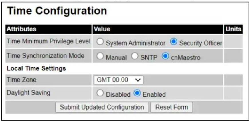
Table 198 cnMaestro clock attributes
| Attribute | Meaning |
| Time Minimum Privilege Level | Minimum security level which is permitted to administer Time security settings.Only displayed when Identity Based User Accounts are Enabled on the User Accounts page (Table 188). |
| Time Synchronization Mode | cnMaestro: the PTP 700 will synchronize with the cnMaestro server during registration, and thereafter at 24-hour intervals. |
| Time Zone | Set the time zone offset from Greenwich Mean Time (GMT).To set the clock to UTC time, set Time Zone to GMT 00.00. |
| Daylight Saving | Disabled: There is no offset for daylight saving time.Enabled: System clock is moved forward one hour to adjust for daylight saving time.To set the clock to UTC time, set Daylight Saving to Disabled. |
Syslog Configuration page
Menu option: Management > Syslog > Syslog configuration (Figure 181).
Use this page to configure system logging. Only users with Security Officer role are permitted to configure the syslog client.
Figure 181 Syslog Configuration page
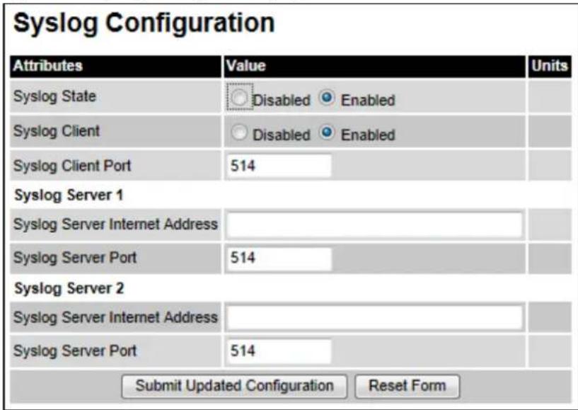

Note To record Coordinated Universal Time (UTC time) in syslog messages, use the Time Configuration page to set Time Zone to GMT 00.00 and Daylight Saving to Disabled (Time Configuration page on page 6-99).
Procedure:
- Update the attributes (Table 199).
- Click Submit Updated Configuration.
Table 199 Syslog Configuration attributes
| Attribute | Meaning |
| Syslog State | When system logging is enabled, log entries are added to the internal log and (optionally) transmitted as UDP messages to one or two syslog servers. |
| Syslog Client | Enabled: Event messages are logged. Disabled: Event messages are not logged. |
| Syslog Client Port | The client port from which syslog messages are sent. |
| Syslog Server 1 and 2: | |
| Syslog Server Internet Address | The FQDN, IPv4 or IPv6 Address of the syslog server. Delete the Internet address to disable logging on the syslog server. |
| Syslog Server Port | The server port at which syslog messages are received. |
SNMP pages (for SNMPv3)
This section describes how to configure Simple Network Management Protocol version 3 (SNMPv3) traps using the SNMP Wizard.
Current SNMP Summary (for SNMPv3)
Menu option: Management > SNMP (Figure 182).
Use this page to review the current SNMP configuration and start the SNMP Wizard.
Figure 182 Current SNMP Summary page (when SNMP is disabled)

Procedure:
- Review the summary.
• If any updates are required, click Continue to SNMP Wizard.
Step 1: SNMP Configuration (for SNMPv3)
Menu option: Management > SNMP. Part of the SNMP Wizard (Figure 183).
Use this page to enable SNMP, select SNMPv3 and configure access to the SNMP server.
Figure 183 Step 1: SNMP Configuration page (for SNMPv3)
Step 1: SNMP Configuration
| Attributes | Value | Units |
| SNMP Minimum Privilege Level | System Administrator Security Officer | |
| SNMP State | Disabled Enabled | |
| SNMP Access Control | Disabled Enabled | |
| SNMP Access Control Internet Address 1 | 1.11.100.5 | |
| SNMP Access Control Internet Address 2 | 2001:DB8::6 | |
| SNMP Access Control Internet Address 3 | 1.11.100.7 | |
| SNMP Version | v1/2c v3 | |
| SNMP Security Mode | MIB-based Web-based | |
| SNMP Engine ID Format | MAC Address IPv4 Address Text String IPv6 Address | |
| SNMP Engine ID Text | ||
| SNMP Port Number | 161 |
Procedure:
- Set SNMP State to Enabled.
- Set SNMP Version to v3. The page is redisplayed with SNMPv3 attributes.
- Update the attributes (Table 200).
- Click Next.
Table 200 Step 1: SNMP Configuration attributes (for SNMPv3)
| Attribute | Meaning |
| SNMP Minimum Privilege Level | Minimum security level which is permitted to administer SNMP security settings.Only displayed when Identity Based User Accounts are Enabled on the User Accounts page (Table 188). |
| SNMP State | Enables or disables SNMP. |
| SNMP Access Control | Enables or disables access control to SNMP management by IP address. |
| SNMP Access Control Internet Address 1/2/3 | A list of up to three IPv4 or IPv6 Addresses permitted to perform SNMP management.Only displayed when SNMP Access Control is set to Enabled. |
| SNMP Version | SNMP protocol version: v1/2c or v3. |
| SNMP Security Mode | MIB-based: SNMPv3 security parameters are managed via SNMP MIBs.Web-based: SNMPv3 security parameters are not available over SNMP, but instead are configured using the SNMP Accounts page, as described in Step 3: SNMP User Policy Configuration (for SNMPv3) on page 6-110. |
| SNMP Engine ID Format | Specifies whether the Engine ID is generated from the MAC Address, IP4 Address, Text String or IPv6 Address. |
| SNMP Engine ID Text | Only enabled when SNMP Engine ID Format is set to Text String. Text used to generate the SNMP Engine ID. |
| SNMP Port Number | The port that the SNMP agent is listening to for commands from a management system. |
Step 2: SNMP MIB-II System Objects (for SNMPv3)
Menu option: Management > SNMP. Part of the SNMP Wizard (Figure 184).
Use this page to enter details of the SNMP managed node.
Figure 184 Step 2: SNMP MIB-II System Objects page (for SNMPv3)

Procedure:
- Update the attributes (Table 201).
- Click Next.
- The next step depends upon which SNMP Security Mode was selected in the Step 1: SNMP Configuration page:
• If Web-based, go to Step 3: SNMP User Policy Configuration (for SNMPv3) on page 6-110.
• If MIB-based, go to Confirm SNMP Configuration (for SNMPv3) on page 6-114.
Table 201 Step 2: SNMP MIB-II System Objects attributes (for SNMPv3)
| Attribute | Meaning |
| Sys Contact | The name of the contact person for this managed node, together with information on how to contact this person. |
| Sys Name | An administratively-assigned name for this managed node. By convention, this is the fully qualified domain name of the node. |
| Sys Location | The physical location of this node, for example Telephone closet, 3rd floor. |
Step 3: SNMP User Policy Configuration (for SNMPv3)
Menu option: Management > SNMP. Part of the SNMP Wizard (Figure 185).
This page is only displayed when SNMP Security Mode is set to Web-based in the Step 1: SNMP Configuration page. Use this page to configure which authentication and privacy protocols are required for SNMP users with roles System administrator and Read only.
Procedure:
- Update the attributes (Table 202).
- Click Next.
Figure 185 Step 3: SNMP User Policy Configuration page (for SNMPv3)
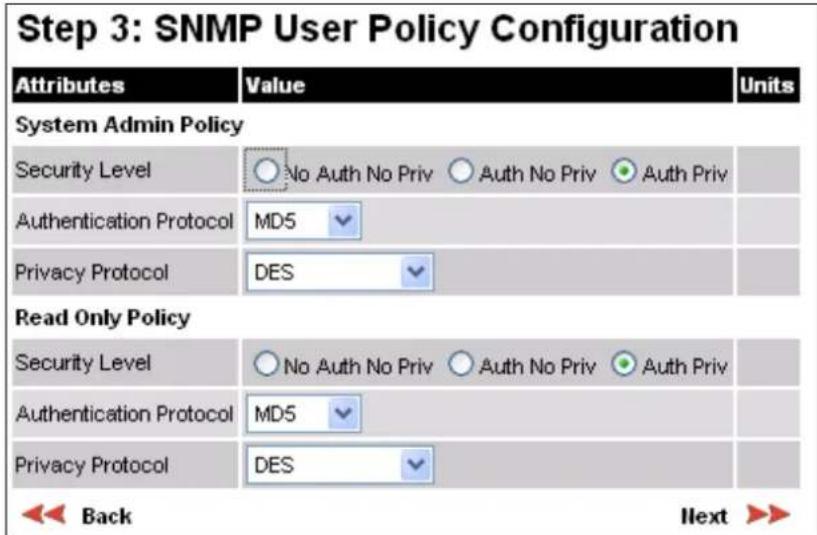
Table 202 Step 3: SNMP User Policy Configuration attributes (for SNMPv3)
| Attribute | Meaning |
| Security Level | Defines the security level and associated protocols that are required to allow SNMP users to access the PTP 700.No Auth No Priv: Users are not required to use authentication or privacy protocols.Auth No Priv: Users are required to use only authentication protocols.Auth Priv: Users are required to use both authentication and privacy protocols. |
| Authentication Protocol | The authentication protocol to be used to access the PTP 700 via SNMP.This is disabled when Security Level is set toAuth No Priv.MD5: Message Digest Algorithm is used.SHA: NIST FIPS 180-1, Secure Hash Algorithm SHA-1 is used. |
| Privacy Protocol | The privacy protocol to be used to access the PTP 700 via SNMP. This is disabled when Security Level is set to No Auth No Priv or Auth No Priv.DES: Data Encryption Standard (DES) symmetric encryption protocol.AES: Advanced Encryption Standard (AES) cipher algorithm. |

Note A user configured to use AES privacy protocol will not be able to transmit and receive encrypted messages unless the license key enables the AES capability.
Step 4: SNMP User Accounts Configuration (for SNMPv3)
Menu option: Management > SNMP. Part of the SNMP Wizard (Figure 186).
This page is only displayed when SNMP Security Mode is set to Web-based in the Step 1: SNMP Configuration page. Use this page to update the SNMP user accounts.
Figure 186 Step 4: SNMP User Accounts Configuration page (for SNMPv3)

Procedure:
- Update the individual user attributes (Table 203) for up to 10 SNMP users.
- Click Next.
Table 203 Step 4: SNMP User Accounts Configuration attributes (for SNMPv3)
| Attribute | Meaning |
| Name | Name to be used by the SNMP user to access the system. |
| Role | Selects which of the two web-based security profiles are applied to this user: System administrator or Read only.Select Disabled to disable the SNMP account. |
| Auth/Priv | Indicates whether the Passphrase applies to authentication or privacy protocols. |
| Passphrase | The phrase to be entered by this SNMP user to access the system using an authentication or privacy protocol. Length must be between 8 and 32 characters. May contain spaces.The Auth Passphrase is hidden when Security Level for this user's Role is set to No Auth No Priv.The Priv Passphrase is hidden when Security Level for this user's Role is set to No Auth No Priv or Auth No Priv. |
| Passphrase Confirm | Passphrase must be reentered to confirm it has been correctly typed. |
Step 5: SNMP Trap Configuration (for SNMPv3)
Menu option: Management > SNMP. Part of the SNMP Wizard (Figure 187).
This page is only displayed when SNMP Security Mode is set to Web-based in the Step 1: SNMP Configuration page. Use this page to configure the events that will generate SNMP traps and to set up trap receivers.
Figure 187 Step 5: SNMP Trap Configuration page (for SNMPv3)

Procedure:
- Update the attributes (Table 204).
- Click Next.
Table 204 Step 5: SNMP Trap Configuration attributes (for SNMPv3)
| Attribute | Meaning |
| SNMP Enabled Traps | Select the events that will generate SNMP traps. |
| SNMP Trap Receiver 1 and SNMP Trap Receiver 2: | |
| SNMP Trap Receiver Enabled | Disabled: SNMP traps are not sent to the corresponding SNMP Trap Receiver (1 or 2).Enabled: SNMP traps are sent to the corresponding SNMP Trap Receiver (1 or 2). |
| SNMP Trap Internet Address | The FQDN, IPv4 or IPv6 Address of the SNMP server (trap receiver). This is normally the network management system, but it may be a separate trap receiver. |
| SNMP Trap Port Number | The server port at which SNMP traps are received. |
| SNMP Trap User Account | The user name (and associated protocols) to use when sending SNMP traps to the server. |
Confirm SNMP Configuration (for SNMPv3)
Menu option: Management > SNMP. Part of the SNMP Wizard (Figure 188).
Use this page to review and confirm the updated SNMPv3 configuration of the unit.
Figure 188 Confirm SNMP Configuration page (for SNMPv3) (top and bottom of page shown)

Procedure:
- To ensure that the changes take effect, click Confirm SNMP Configuration and Reboot. The unit reboots and the changes take effect.
SNMP pages (for SNMPv1/2c)
This section describes how to configure Simple Network Management Protocol version 1 or 2c (SNMPv1 or SNMPv2c) traps using the SNMP Wizard.
Current SNMP Summary (for SNMPv1/2c)
Menu option: Management > SNMP (Figure 182).
Use this page to review the current SNMP configuration and start the SNMP Wizard.
Procedure:
- Review the summary.
• If any updates are required, click Continue to SNMP Wizard.
Step 1: SNMP Configuration (for SNMPv1/2c)
Menu option: Management > SNMP. Part of the SNMP Wizard (Figure 189).
Use this page to enable SNMP, select SNMPv1/2c and configure access to the SNMP server.
Figure 189 Step 1: SNMP Configuration page (for SNMPv1/2c)

Procedure:
- Set SNMP State to Enabled.
- Set SNMP Version to v1/2c. The page is redisplayed with SNMPv1/2c attributes.
- Update the attributes (Table 205).
- Click Next.
Table 205 Step 1: SNMP Configuration attributes (for SNMPv1/2c)
| Attribute | Meaning |
| SNMP Minimum Privilege Level | Minimum security level which is permitted to administer SNMP security settings.Only displayed when Identity Based User Accounts are Enabled on the User Accounts page (Table 188). |
| SNMP State | Enables or disables SNMP. |
| SNMP Access Control | Enables or disables access control to SNMP management by IP address. |
| SNMP Access Control Internet Address 1/2/3 | A list of up to three IPv4 or IPv6 Addresses permitted to perform SNMP management.Only displayed when SNMP Access Control is set to Enabled. |
| SNMP Version | SNMP protocol version: v1/2c or v3. |
| SNMP Community String | The SNMP community string acts like a password between the network management system and the distributed SNMP clients (PTP 700 ODUs). Only if the community string is configured correctly on all SNMP entities can the flow of management information take place. By convention the default value is set to public. |
| SNMP Port Number | Enter the port that the SNMP agent is listening to for commands from a management system. |
Step 2: SNMP MIB-II System Objects (for SNMPv1/2c)
Menu option: Management > SNMP. Part of the SNMP Wizard (Figure 184). Use this page to enter details of the SNMP managed node. Update the attributes (Table 201) and click Next.
Step 3: SNMP Trap Configuration (for SNMPv1/2c)
Menu option: Management > SNMP. Part of the SNMP Wizard (Figure 190).
Figure 190 Step 3: SNMP Trap Configuration page (for SNMPv1/2c)

Procedure:
- Update the attributes (Table 206).
- Click Next.
Table 206 Step 3: SNMP Trap Configuration attributes (for SNMPv1/2c)
| Attribute | Meaning |
| SNMP Trap Version | Select the SNMP protocol version to use for SNMP traps: v1 or v2c. |
| SNMP Enabled Traps | Select the events that will generate SNMP traps. |
| SNMP Trap Receiver Enabled | Disabled: SNMP traps are not sent to the corresponding SNMP Trap Receiver (1 or 2).Enabled: SNMP traps are sent to the corresponding SNMP Trap Receiver (1 or 2). |
| SNMP Trap Internet Address | The FQDN, IPv4 or IPv6 Address of the SNMP server (trap receiver). This is normally the network management system, but it may be a separate trap receiver. |
| SNMP Trap Port Number | The server port at which SNMP traps are received. |
Confirm SNMP Configuration (for SNMPv1/2c)
Menu option: Management > SNMP. Part of the SNMP Wizard (Figure 191).
Use this page to review and confirm the updated SNMPv1/2c configuration of the unit.
Figure 191 Confirm SNMP Configuration page (for SNMPv1/2c) (top and bottom of page shown)

Procedure:
- To ensure that the changes take effect, click Confirm SNMP Configuration and Reboot. The unit reboots and the changes take effect.
Template Manager
Menu option: Template Manager
This section describes how to create, import, export and delete custom configuration templates.
Template Description
Use this section to examine the details of an installed standard or custom template.
Figure 192 Template Manager page, Template Description
| Attributes | Value | Units |
| Template Description | ||
| Template Name | Best Performance✓ | |
| Software Version | 03.65 | |
| Serial Number | 00:04:56:58:00:b8 | |
| License Compatibility | Yes | |
| Software Version Compatibility | Yes | |
Table 207 Template Description attributes
| Attribute | Meaning |
| Template Name | Displays the details of the selected Template. |
| Software Version | The firmware version used to create the template. A template cannot be used where the ODU has a newer version than the template. |
| Serial Number | The MAC Address of the ODU used to create the template. |
| License Compatibility | Yes: All of the capabilities used in the template are licensed in the ODU License Key.No: One or more of the capabilities used in the template is not licensed in the ODU License Key. The template is not compatible. |
| Software Version Compatibility | Yes: The firmware version used to create the template is not newer than the firmware installed in the ODU.No: The firmware version used to create the template is newer than the firmware installed in the ODU. The template is not compatible. |
Create Template
Use this section to create new custom templates.
Figure 193 Template Manager page, Create Template

Table 208 Template Description attributes
| Attribute | Meaning |
| Template Type | New Template: Create a new custom template in an empty template slot.Replace Existing Template: Create a new custom template to replace an existing template, overwriting the occupied template slot. |
| Existing Template | Select the existing template to be overwritten. |
| Template Name | Enter a descriptive and unique name for the new template. |
| Editable Controls | Select the attributes that will be available for the Installer user to configure as part of installation. For attributes that are not selected, the current value will be saved in the template. |
Import Template
Use this section to import a template file from a management device into an empty template slot on the ODU.
Procedure:
- Click the Choose File button and select a template file from the file system of the management device. Template files have a ".template" extension.
- Click Import Template File.
Figure 194 Template Manager page, Import Template

Export Template
Use this section to export a custom template file to a management device.
Procedure:
- Select the Template to export.
- Click Export Template File.
Figure 195 Template Manager page, Export Template
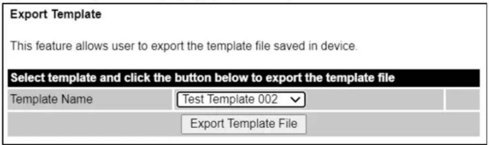
Delete Template
Use this section to delete a custom template file on the ODU, leaving an empty template slot.
Procedure:
- Select the custom template to export, or select Delete All Templates.
- Click Delete Template.
Figure 196 Template Manager page, Delete Template

Security menu
This section describes how to configure security options using the Security Wizard.
To configure security for the FIPS 140-3 approved mode, read this section and additionally read Configuring security for FIPS 140-3 applications on page 6-137.

Attention Ensure that the operator's security requirements are configured before connecting the PTP 700 to the network. Otherwise, security may be compromised.
Preparation
Obtain the necessary cryptographic material as described in:
• Using the Security Wizard on page 3-69.
• Planning for wireless encryption on page 3-70.
- Planning for HTTPS/TLS operation on page 3-72.
• Planning for protocols and ports on page 3-73.
Ensure that the ODU has the AES license. If necessary, order the necessary AES capability upgrade, generate a license key (Generating license keys on page 6-2) and enter it on the Software License Key page (Software License Key page on page 6-16).
On the Local User Accounts page (Local User Accounts page on page 6-85), check that:
• Either: Identity Based User Accounts are set to Disabled,
- Or: Identity Based User Accounts are set to Enabled and the current user's role is Security Officer.
Security Configuration Wizard page
Menu option: Security. Displayed only when AES encryption is enabled by license key (Figure 197). Use this page to review the current security configuration of the unit.
Figure 197 Security Configuration Wizard page
Security Configuration Wizard
This page shows a summary of the current security configuration. Press the 'Continue to Security Wizard' button below to change this configuration.
Security configuration
| Attributes | Value | Units | |
| Key of Keys | Not configured | ||
| DRNG Entropy | Not configured | ||
| User Defined Security Banner | |||
| Require Acknowledgement Of Notices | No | ||
| Display Login Information | No | ||
| HTTPS Access Enabled | No | ||
| Encryption Algorithm | TLS RSA | ||
| TLS Minimum Security Level | None | ||
| Device Certificate | Factory | ||
| Authorization Method | Blacklist | ||
| HTTP Access Enabled | Yes | ||
| HTTP Port Number | 80 | ||
| Telnet Access Enabled | No | ||
| SNMP Control Of HTTP And Telnet | Enabled | ||
| SNMP Control Of Passwords | Disabled | ||
| TFTP Client | Enabled | ||
| Debug Access Enabled | Yes | ||
| Cross Site Request Forgery Protection | Enabled | ||
| Continue to Security Wizard | |||
To continue with the Security Wizard, click Continue to Security Wizard.
Security options
Menu option: Security. Part of the Security Wizard (Figure 198).
Select optional security features.
Keys of Keys, Entropy, and HTTP and Telnet Options are always enabled.
Set the remaining options to No to disable the associated feature, or set to Yes to enable the associated feature. Enabled features are configured in the remaining pages of the Security Wizard.
Figure 198 Security Options page

Key of Keys
Menu option: Security. Part of the Security Wizard (Figure 199 to Figure 201).
Use this page to enter a Key of Keys to encrypt all sensitice security parameters (SSPs) before they are stored in non-volatile memory.
Figure 199 Key of Keys page

Click on the Show button to display the entered value as standard text.
Figure 200 Key of Keys page showing entered value

Figure 201 Key of Keys page with configured value


Note The Key of Keys attribute can be configured using the Security Wizard. It cannot be updated after the Security Wizard is submitted, except by first zeroizing SSPs.
Procedure:
- Enter and confirm the generated Key of Keys.
- Click Generate Random Key to enter an internally-generated random key
- Click Next.
Entropy
Menu option: Security. Part of the Security Wizard (Figure 202 and Figure 203).
Use this page to enter entropy Configure to seed the internal random number algorithm.
Figure 202 Entropy page

Figure 203 Entropy page with configured value

Procedure:
- If a valid entropy value exists, then a thumbprint of the Entropy value is displayed. The thumbprint is the final four octets (32 bits) of a SHA2-256 digest of the Entropy value formatted as a text string. If this thumbprint is correct, then take no action. Otherwise, enter the generated value in the Entropy Input and Confirm Entropy Input fields.
- Click Generate Random Key to enter an internally-generated random key
- Click Next.
Enter User Security Banner
Menu option: Security. Part of the Security Wizard (Figure 204).
Use this page to enter a banner that will be displayed every time a user attempts to login to the wireless unit.
Figure 204 Enter User Security Banner page
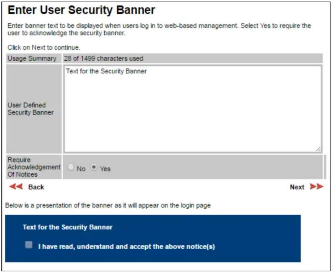
Procedure:
- Update the User Defined Security Banner (optional).
- Set the Acknowledgement to No or Yes.
- Click Next.
Enter Login Information Settings
Menu option: Security. Part of the Security Wizard (Figure 205).
Use this page to choose whether or not to display information about previous login attempts when the user logs into the web interface.
Figure 205 Enter Login Information Settings page
Enter Login Information Settings
Login Information provides details of the most recent successful login and unsuccessful login attempts. An example of Login Information is shown below. Click on Next to continue.
| Attributes | Value | Units |
| Display Login Information | No Yes | |
| Back | Next >> | |
Below is a presentation of the Login Information as it will appear on the login page:
Successful login
| Time Of Last Login | 14-Jun-2017 14:04:15 |
| Internet Address Of Last Login | 169.254.1.100 |
| Unsuccessful login attempts | |
| Number Of Unsuccessful Login Attempts | 1 |
| New Unsuccessful Login Attempts | 0 |
| Time Of Last Unsuccessful Login Attempt | 14-Jun-2017 14:04:13 |
| Internet Address Of Last Unsuccessful Login Attempt | 169.254.1.100 |
Procedure:
- Set Display Login Information to No or Yes.
- Click Next.
Enter HTTPS Configuration
Menu option: Security. Part of the Security Wizard (Figure 206 and Figure 207).
Use this page to select and upload the HTTPS/TLS Private Key and Public Certificate files.
Figure 206 Enter HTTPS Configuration page
Enter HTTPS Configuration
Upload the RSA Private Key and Public Certificate for the HTTPS interface using 2048-bit key size and SHA256. The certificate subject must be the ODU's IP Address, for example 169.254.1.1. Input must be in Distinguished Encoding Rules (DER) format.
Click on Next to continue.
| HTTPS Port Number | 443 | ||
| TLS Private Key | Choose File | key-1119.der | DER format |
| TLS Public Certificate | Choose File | cert-1119.der | DER format |

Back
Next

Figure 207 Configured HTTPS Configuration page


Attention If the certificates expire, your web browser will display security warnings. Always investigate the cause of security warnings and rectify errors in the content or expiry of certificates where necessary. Do not accept or ignore web browser security warnings.
Procedure:
- If a valid TLS private key exists, then a thumbprint of the key is displayed. The thumbprint is the final four octets (32 bits) of a SHA2-256 digest of the private key. If this key is correct, then take no action. Otherwise, click Browse and select the generated private key file (.der).
- If a valid TLS public certificate exists, then a thumbprint of the certificate is displayed. The thumbprint is the final four octets (32 bits) of a SHA2-256 digest of the certificate. If this certificate is correct, then take no action. Otherwise, click Browse and select the generated certificate file (.der).
- Click Next.
Configure Wireless Security
Menu option: Security. Part of the Security Wizard (Figure 208 to Figure 212).
Use this page to enable device authentication and authorization, and AES encryption of the wireless link. Wireless link encryption key is used to encrypt all traffic over the PTP 700 wireless link.
Figure 208 Wireless Link Encryption Settings, TLS-RSA
Enter Wireless Link Encryption Settings
Wireless Security provides device authentication and privacy at the wireless interface. Select the same Encryption Algorithm for the local and remote ODUs.
With the TLS RSA option select "Factory" to use the factory-installed key and certificate or "User" to provide a user-generated key and certificate in a later page. Select the minimum security level that can be allowed in the link. With the TLS PSK options, provide a pre-shared key in a later page.
Click on Next to continue.
| Attributes | Value | Units |
| Encryption Algorithm | None TLS RSA TLS PSK 128-bit TLS PSK 256-bit | |
| Device Certificate | Factory User | |
| TLS Minimum Security Level | AES 256-bit TLS RSA ▼ | |
| Rekey Interval | 1440 | minutes |
| Back | Next ▶ | |
Figure 209 Wireless Link Encryption Settings, User-supplied device certificates
Enter User Device Certificates
Upload the RSA Root CA, Private Key and Public Certificate for device authentication using 2048-bit key size and SHA256. The certificate subject must be the ODU's Unit ESN as 12 hexadecimal characters without punctuation. For example 000456500EF3. The Root CA certificate must form a valid certificate chain with the Public Certificate for the remote ODU. Input must be in Distinguished Encoding Rules (DER) format.
Click on Next to continue.
| Device Root CA | Choose File | No file chosen | DER format |
| Device Private Key | Choose File | No file chosen | DER format |
| Device Public Certificate | Choose File | No file chosen | DER format |

Back
Next

Figure 210 Wireless Link Encryption Settings, Authorization Control

Figure 211 Wireless Link Encryption Settings, TLS-PSK
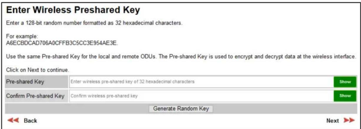
Figure 212 Wireless Link Encryption Settings, TLS-PSK with configured value
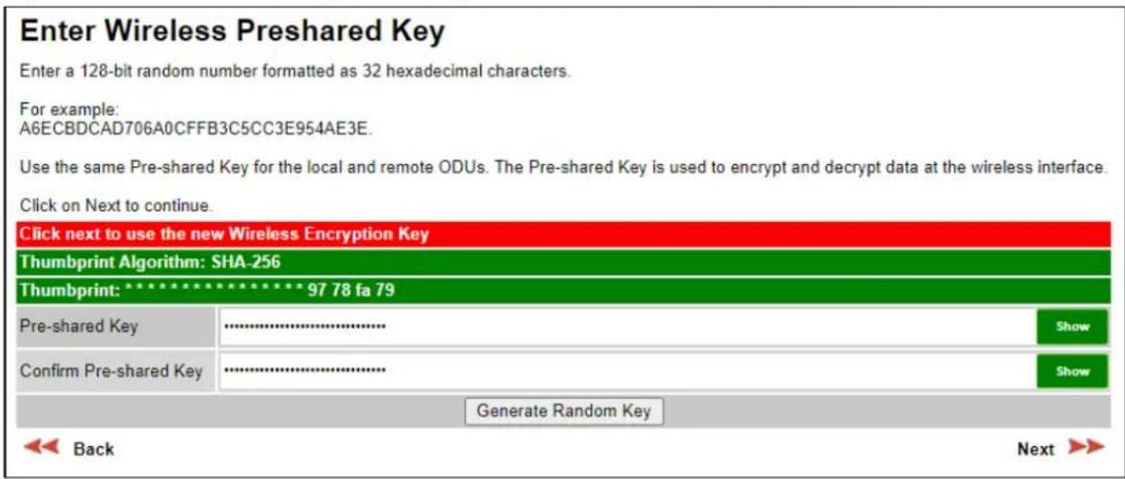
Procedure:
- Select the applicable value in the Encryption Algorithm field.
- For TLS-RSA, select Factory or User device certificates.
- For User device certificates, install Private Key, Public Certificate and Root CA certificate.
- For TLS-RSA and Group Access, configure the Whitelist or Blacklist
- For TLS-PSK, configure the pre-shared key. If a valid encryption key exists, then a thumbprint of the key is displayed. The thumbprint is the final four octets (32 bits) of a SHA2-256 digest of the pre-shared key. If this key is correct, then take no action.
• For TLS-PSK, click Generate Random Key to enter an internally-generated random key - Click Next.
HTTP and Telnet options
Menu option: Security. Part of the Security Wizard (Figure 213).
Use this page to configure network management of the PTP 700 using one or more of the following methods: HTTPS, HTTP, Telnet or SNMP.
Figure 213 HTTP and Telnet Settings page
Enter HTTP and Telnet Settings
Configure HTTP, Telnet, TFTP and Debug Access.
WARNING: Management access will be impossible if HTTP, HTTPS and SNMP are all disabled.
To-regain access, operate the ODU in recovery mode WARNING: Management access will be impossible if HTTP, HTTPS and SNMP are all disabled. To re-gain access, operate the ODU in recovery mode and select "Reset IP and Ethernet Configuration". Click on Next to see a summary of the security configuration.
| Attributes | Value | Units |
| HTTP Access Enabled | No Yes | |
| HTTP Port Number | 80 | |
| Telnet Access Enabled | No Yes | |
| SNMP Control Of HTTP And Telnet | Disabled Enabled | |
| SNMP Control Of Passwords | Disabled Enabled | |
| TFTP Client | Disabled Enabled | |
| Debug Access Enabled | No Yes | |
| Cross Site Request Forgery Protection | Disabled Enabled |


Attention If HTTPS, HTTP, Telnet and SNMP are all disabled, management access will be impossible until the unit is placed in recovery mode.
Note If HTTP, Telnet and SNMP are all disabled, the secure web server becomes the only management tool for the ODU web interface. To reenter the web interface after Step 7 of the Security Wizard, use the URL https://aa.bb.cc.dd (where aa.bb.cc.dd is the IP address of the unit).
Review and update the HTTP and Telnet attributes (Table 209) and click Next.
Table 209 HTTP and Telnet attributes
| Attribute | Meaning |
| HTTP Access Enabled | No: The unit will not respond to any requests on the HTTP port.Yes: The unit will respond to requests on the HTTP port.Remote management via HTTPS is not affected by this setting. |
| HTTP Port Number | The port number for HTTP access. Zero means use the default port. |
| Telnet Access Enabled | No: The unit will not respond to any requests on the Telnet port.Yes: The unit will respond to requests on the Telnet port. |
| Telnet Port Number | The port number for Telnet access. Zero means use the default port. |
| SNMP Control of HTTP And Telnet | Disabled: Neither HTTP nor Telnet can be controlled remotely via SNMP.Enabled: Both HTTP and Telnet can be controlled remotely via SNMP. |
| SNMP Control of Passwords | Enabled:Passwords for identity-based user accounts in the web-based interface can be updated via SNMP. Use this with SNMPv3 to provide secure password updating from a central network manager. Disabled:Passwords for identity-based user accounts can be updated only via the web-based interface (default). |
| TFTP Client | Enabled:The unit will respond to TFTP firmware download requests. |
| Debug Access Enabled | Yes:Cambium Technical Support is allowed to access the system to investigate faults. |
| Cross Site Request Forgery Protection | Enabled:The system is protected against cross-site request forgery attacks at the web-based interface. |
Confirm Security Configuration
Menu option: Security. Part of the Security Wizard (Figure 214).
Use this page to review and confirm the updated security configuration of the unit.
Figure 214 Confirm Security Configuration page
Confirm Security Configuration
Press the button to confirm the security configuration and reboot the ODU.
| Attributes | Value | Units |
| Key of Keys | Modified | |
| DRNG Entropy | Modified | |
| User Defined Security Banner | ||
| Require Acknowledgement Of Notices | No | |
| Display Login Information | Yes | |
| HTTPS Access Enabled | Yes | |
| HTTPS Port Number | 443 | |
| Private Key | Modified | |
| Public Certificate | Modified | |
| Encryption Algorithm | TLS PSK 128-bit | |
| Wireless Encryption Key | Modified | |
| HTTP Access Enabled | Yes | |
| HTTP Port Number | 80 | |
| Telnet Access Enabled | No | |
| SNMP Control Of HTTP And Telnet | Enabled | |
| SNMP Control Of Passwords | Disabled | |
| TFTP Client | Enabled | |
| Debug Access Enabled | Yes | |
| Cross Site Request Forgery Protection | Enabled | |
| Confirm Security Configuration and Reboot | ||

Back
Procedure:
- Review all changes that have been made in the Security Wizard.
- To ensure that the changes take effect, click Commit Security Configuration and Reboot. The unit reboots and the changes take effect.
Zeroize SSPs page
Menu option: Security > Zeroize SSPs (Figure 215).
Use this page if it is necessary to reset the security configuration to default values.
Figure 215 Zeroize SSPs page
Zeroize SSPs
Press the Zeroize SSPs button to reset security configuration and reboot the wireless unit.
The security configuration includes the sensitive security parameters (SSPs).
The following security-related attributes will be reset to their default values:
- Key of Keys
- Encryption Algorithm
- Wireless Encryption Key
- TLS Minimun Security Level
- Rekey Interval
- User Private key
- User Public Key Certificate
- User Root Certificate
- HTTPS Private Key
- HTTPS Public Key Certificate
- SSO IDP Metadata
- Random Number Generator Entropy
- HTTP Access Enabled
- HTTP Port Number
- SNTP Security Configuration
- SNMPv3 Configuration
- Local User Accounts Names, Roles and Passwords
Zeroize SSPs and Reboot Wireless Unit
Procedure:
- Click Zeroize SSPs and Reboot Wireless Unit.
- Confirm the reboot.

Attention When SSPs have been zeroized, all user accounts are disabled, and the ODU is returned to the "first use" condition. See Creating a user account on page 6-6 to create a new user account for the web-based interface.
Configuring security for FIPS 140-3 applications
This is a summary of all the configuration tasks that are necessary if the unit is to operate in FIPS 140-3 approved mode. For more information, refer to FIPS 140-3 mode on page 1-82 and Security planning on page 3-68.
The common steps for configuring security are described in Security menu on page 6-122.
Prerequisites for FIPS 140-3 configuration
Use this procedure to confirm that all prerequisites for FIPS 140-3 are ready.
Procedure:
1 Ensure that the following cryptographic material has been generated using a FIPS-approved cryptographic generator:
• Key Of Keys
- TLS Private Key and Public Certificates (for the correct IP address) with 2048-bit key size, and signed using the SHA2-256 Secure Hash Algorithm.
- Entropy Configure
- Wireless Link Encryption Key for AES
2 Identify the Port number for HTTPS.
3 Ensure that the web browsers used are enabled for HTTPS/TLS operation using FIPS-approved cipher specifications.
4 On the Management, Web menu, click Local User Accounts and check that the current user's role is Security Officer.
5 Ensure that the installed license key meets all requirements including FIPS 140-3 compatibility:
- Check that Security Level is "FIPS".
- Check that Encryption Algorithm is "AES...".
- If necessary, generate and enter a new license key with the above settings and install as described in Software License Key page on page 6-16.
6 Ensure that the installed firmware version is prefixed "FIPS-". If necessary, upgrade to the latest FIPS validated image as described in Software Upgrade page on page 6-80.
7 To confirm that the above steps have been completed, check that the FIPS 140-3 logo is displayed in the Navigation Bar:
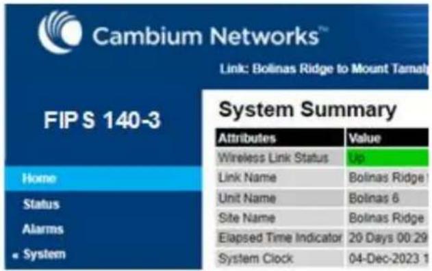
Configuration procedures for FIPS 140-3
To operate the ODU in FIPS 140-3 secure mode:
- Perform the steps in Local User Accounts page on page 6-85, taking care to configure appropriate identity-based user names and passwords.
• Perform the steps described in Security menu on page 6-122.
Checking that the unit is in the FIPS 140-3 operational state
Use this procedure to confirm that the unit is now in the FIPS 140-3 operational state:
Procedure:
1 On the menu, click Security and check the Secure Mode Alarm value.
2 If the alarm is "Secure mode is active", the unit is in FIPS 140-3 secure mode and no further action is needed.
Security Configuration Wizard
This page shows a summary of the current security configuration. Press the 'Continue to Security Wizard' button below to change this configuration.
Security configuration
| Attributes | Value | Units |
| Secure Mode Alarm | Secure Mode Is Active | |
| Key of Keys | Configured | |
| Private Key | Configured | |
| Public Certificate | Configured |
If the alarm is "Secure mode is not configured", return to Security menu on page 6-122 and check that all Security Wizard settings are correct for FIPS 140-3.
Security Configuration Wizard
This page shows a summary of the current security configuration.
Press the 'Continue to Security Wizard' button below to change this configuration.
Security configuration
| Attributes | Value | Units |
| Secure Mode Alarm | Secure Mode Is Not Configured | |
| Key of Keys | Not configured | |
| Private Key | Not configured | |
| Public Certificate | Not configured |
If this alarm is displayed, it is also displayed in the System Summary page.
4 If the alarm is "Secure mode is configured, but not active", return to HTTP and Telnet options on page 6-132 and check that HTTP Access Enabled is set to No.
If this alarm is displayed, it is also displayed in the System Summary page.

Note If it is necessary to exit from FIPS 140 2 mode, refer to Managing security on page 7-57.
External Devices
TD-90 antenna positioner
The External Devices pages are added in the navigation bar when the TD-90 Service is Enabled.
Integrated management of the TD-90 provides a set of web pages with organization and controls for remote management of the TD-90, closely replicating the local web-based management of the TD-90. For further details about managing TD-90, please see Cambium TD-90 Antenna Positioner User Guide.

Note The TD-90 antenna positioner cannot be used at an HCMP Master ODU.
System Summary
The System Summary page provides important identification, configuration and overall fault status for the TD-90 antenna positioner.
Figure 216 TD-90 System Summary page
| TD90 - System Summary | Remote Side | ||||
| Attributes | Value | Units | Attributes | Value | Units |
| Positioner Name | TD90Master | Remote State | Stopped / Init | ||
| Positioner Serial Number | 30251 | Remote Geodetic Position | |||
| Positioner Model Number | TD-90 | Azimuth | 0.0 | degrees | |
| Positioner Part Number | C000000L069A | Elevation | 0.0 | degrees | |
| Manufacturer Date | 8MAR19 | Latitude | 0.000000 | ||
| Firmware Version | CMB-1.29.59 | Longitude | 0.000000 | ||
| GPS Status | Connected | Altitude | 0.0 | meters | |
| Operating Mode | Manual | ||||
| Setup Status | Complete | ||||
| Error Status | 0 | ||||
| Geodetic Position | |||||
| Azimuth | 292.2 | degrees | |||
| Elevation | 0.0 | degrees | |||
| Latitude | 28.015205 | ||||
| Longitude | -82.427898 | ||||
| Altitude | 3.3 | meters | |||
| Radio / Tracking | |||||
| Radio Connection | Connected | ||||
| Positioner State | Stopped / Init | ||||
System Setup
The System Setup page provides a single page dedicated for setup and pre-configuration of a TD-90 positioner to work in Mode 1, 2, or 3.
Figure 217 TD-90 System Setup page
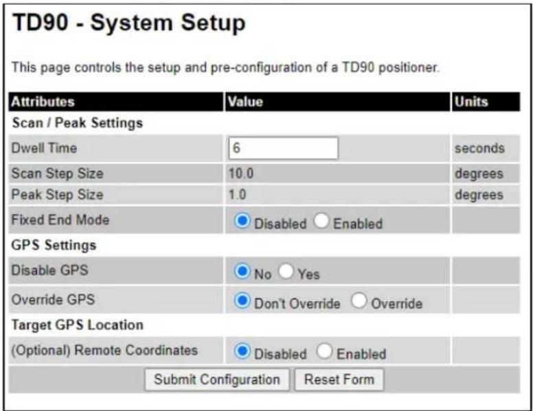
Manual Control
The Manual Control page provides a tool to manually move a TD-90 positioner by slewing around or commanding to a specific azimuth and elevation.
Figure 218 TD-90 Manual Control page

Positioner Configuration
The Positioner Configuration page provides a tool to set TD-90 positioner configuration items such as pedestal limits, stow position, orientation of installation, and unit name.
Figure 219 TD-90 Positioner Configuration page

Firmware Upgrade
The Software Upgrade page allows updates of TD-90 firmware.
Figure 220 TD-90 Software Upgrade page

Compass Setup
The Compass Setup page provides a tool to monitor and configure the onboard TD-90 magnetic compass. Due to the fact that the TD-90 is tactical and moved to various locations where magnetic environments can change, it is necessary to have the ability to monitor and re-calibrate the on-board compass. The compass is only required for Mode 1 and 2 operation and is intended to help speed up the acquisition time to establish a radio link. Mode 3 is the default mode and will establish a radio link with no GPS or Compass aid.
Figure 221 TD-90 Compass Setup page

Errors
The Errors page provides a window to monitor error conditions. An error indicator does not necessary indicate the TD-90 will not establish a link but may explain why a particular link takes longer to acquire or switch acquisition modes. Figure 222 shows the Errors page when no error conditions have been detected.
Figure 222 TD-90 Errors page

Reboot
The Reboot page provides a way to reboot the attached TD-90 from the PTP 700 ODU.
Figure 223 TD-90 Reboot page

Aligning fixed beam antennas
This section describes how to align the antennas for Master and Slave ODUs in the PTP topology, and Slave ODUs in the HCMP topology, using the web interface to assist with alignment, and checking wireless performance after alignment.
Use this procedure for Integrated, Connectorized or Connectorized+Integrated ODUs, or for Beam Steering ODUs with Automatic Alignment disabled.
Hardware installation
Check that hardware installation of ODUs and antennas is complete, and that antennas have been approximately aligned using compass bearing or by reference to landmarks or other geographical features.
Ensure that the ODUs are powered up.
Management connection
Connect suitable management stations (typically laptops) to Master and Slave ODUs, as described in Connecting to the unit on page 6-4. Log into the local unit as described in Logging into the web interface on page 6-7.
Arm the ODUs for installation
Use this procedure to confirm that the units are in the armed state, ready for alignment.
In the armed state, the modulation mode is fixed at BPSK 0.63 Single, and automatic transmit power control is disabled.
Procedure:
- Select menu option Home. The System Summary page is displayed.
- Check that the Install Arm State is set to Armed.
- If the units are not armed, use the installation wizard as described in Standard Installation menu on page 6-12 to configure Installation Mode to Arm With Tones or Arm Without Tones.
Aligning antennas
Use this procedure to manually align fixed beam integrated or connectorized antennas at Master and Slave ODUs. The goal of antenna alignment is to find the center of the main beam. This is done by adjusting the antennas while monitoring the receive signal level.
Preparation:
Ensure that the following parameters are available:
- Location of both sites (latitude and longitude).
- Bearing to the other end of the link for both sites.
• Prediction of receive signal level for both ends of the link.
• Prediction of link loss.
LINKPlanner provides all of these parameters in the form of an installation report.
If a connectorized ODU is installed at either site with two separate antennas for spatial diversity, refer to Aligning separate antennas for spatial diversity on page 6-145 before starting alignment.

Note For improved radio performance, mount the integrated ODU at 45 degrees to the vertical; this ensures that side-lobe levels are minimized for interference transmitted or received at zero elevation.
To achieve best results, make small incremental changes to elevation and azimuth.

Attention The action of tightening the mounting bolts can alter antenna alignment. This can be helpful when fine-tuning alignment, but it can also lead to misalignment. To prevent misalignment, continue to monitor receive signal level during final tightening of the bolts.
Procedure:
1 Without moving the master antenna, adjust the elevation and azimuth of the slave antenna to achieve the highest receive signal level using one of the following methods:
• ODU installation tones on page 6-146
• Graphical Install page on page 6-147
2 Without moving the Slave antenna, adjust the elevation and azimuth of the Master antenna to achieve the highest receive signal level (using one of the above methods).
3 Repeat steps 1 and 2 as necessary to fine-tune the alignment to find the center of the beam.
4 When the antennas have been aligned on the center of the beam, verify that the receive level is within the predicted range (from the installation report). If this is not the case, go back to step 1. The current value of receive level can be verified by using the graphical installation method (see Graphical Install page on page 6-147) or by selecting menu option Status and monitoring the Receive Power attribute on the System Status page.
5 If after repeated attempts to align, the receive level still does not lie within the predicted range, this may be because the data provided to the prediction tool (such as LINKPlanner) is inaccurate. For example estimates of path obstructions, antenna heights or site locations may be inaccurate. Check this data and update the prediction as necessary.
6 Once the antennas have been aligned correctly, tighten the integrated ODU (or connectorized antenna) mountings. To ensure that the action of tightening does not alter antenna alignment, continue to monitor received signal level.
Aligning separate antennas for spatial diversity
Use this procedure if a connectorized ODU is installed at either site with two separate antennas for spatial diversity.
Procedure:
1 Connect the horizontal polarization antenna to the ODU, disconnect the vertical polarization antenna, then perform Aligning antennas on page 6-144.
2 Connect the vertical polarization antenna to the ODU, disconnect the horizontal polarization antenna, then perform Aligning antennas on page 6-144.
3 Re-connect the horizontal polarization antennas. The received signal level should increase.
4 Weatherproof the antenna connections at the "H" and "V" interfaces of the ODUs, as described in Weatherproofing an N type connector on page 5-57.
ODU installation tones
This is the first of two methods that may be used to monitor receive signal level during antenna alignment.
The ODU emits audible tones during installation to assist with alignment. The pitch of the alignment tone is proportional to the received power of the wireless signals. Adjust the alignment of the unit in both azimuth and elevation until the highest pitch tone is achieved.

Note When using ODU installation tones to align connectorized antennas, it may not be possible to hear the tones. To overcome this problem, either use an assistant, or use a stethoscope to give a longer reach.
The tones and their meanings are described in Table 210. In each of the states detailed in the table, align the unit to give the highest pitch tone. The term “wanted signal” refers to that of the peer unit being installed.
Table 210 ODU installation tones
| State Name | Tone Description | State Description | Pitch Indication |
| Free Channel Search | Regular beep | Executing band scan | N/A |
| Scanning | Slow broken tone | Not demodulating the wanted signal | Rx Power |
| Synchronized | Fast broken tone | Demodulating the wanted signal | Rx Power |
| Registered | Solid tone | Both Master and Slave units exchanging Radio layer MAC management messages | Rx Power |

Attention If, when in the Synchronized or Registered state, the tone varies wildly, there may be interference or a fast fading link. Installing in this situation may not give a reliable link. Investigate the cause of the problem.
During alignment, the installation tones should exhibit the following behavior:
- Band scan: When first started up and from time to time, the Master unit will carry out a band scan to determine which channels are not in use. During this time, between 10 and 15 seconds, the Master unit will not transmit and as a consequence of this neither will the Slave unit. During this time the installation tone on the master unit will drop back to the band scan state, and the Slave unit will drop back to the Scanning state with the pitch of the tone set to the background noise level. Alignment of the unit should cease during this time.
- Radar detection: If the unit is operating where mandatory radar avoidance algorithms are implemented, the ranging behavior may be affected. The Master has to monitor the initially chosen channel for 60 seconds to make sure it is clear of radar signals before transmitting. If a radar signal is detected during any of the installation phases, a further compulsory 60 seconds channel scan will take place as the master unit attempts to locate a new channel that is free of radar interference.
- Ranging: The PTP 700 Series does not require the user to enter the link range. The Master unit typically takes less than 60 seconds to determine the length of the link being installed. The Master unit will remain in the Scanning state until the range of the link has been established. The Master unit will only move to the Synchronized state when the range of the link has been established.
The Slave unit does not have a ranging process. The slave unit will change to the Synchronized state as soon as the wanted signal is demodulated.
- Retrying same channel: If, at the end of the ranging period, the Registered state is not achieved due to interference or other reasons, the Master unit will retry twice more on the same channel before moving to another available channel. Should this occur it may take a number of minutes to establish a link in the Registered state.
Graphical Install page
Menu option: Installation > Graphical Install (Figure 224).
This is the second of two methods that may be used to monitor receive signal level during antenna alignment.
Figure 224 Graphical Install page
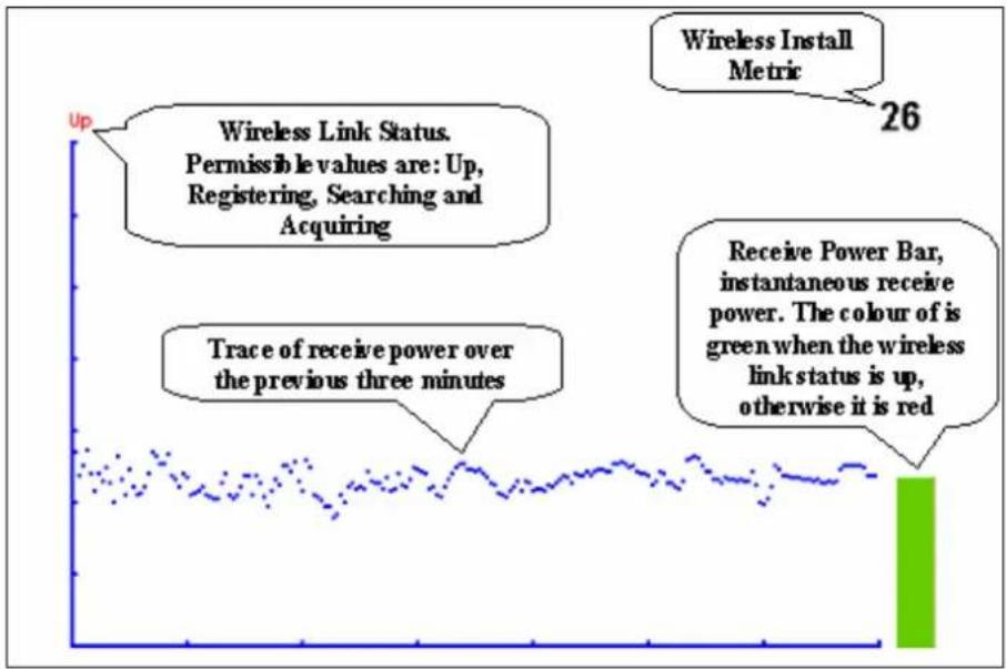
line
| Metric | Value | | --- | --- | | Wireless Install Metric | 26 | | Wireless Link Status | Permissible values are: Up, Registering, Searching and Acquiring | | Trace of receive power over the previous three minutes | | | Receive Power Bar, instantaneous receive power. The colour of is green when the wireless link status is up, otherwise it is red | |Procedure:
- Check that Wireless Link Status (top left) is "Up", "Registering", "Searching" or "Acquiring".
- While slowly sweeping the antenna, monitor the trace of receive power over the last three minutes.
- Monitor the Receiver Power Bar (bottom right). Green signifies that the wireless link is up and red signifies all other states.
- Monitor the Wireless Install Metric (top right). This is the instantaneous receive power in dBm + 110.

Note To access the PDA version of the graphical installation tool, use this URL - http://
Disarming the units
When antenna alignment is complete, use this procedure to disarm both units in the link in order to:
- Turn off the audible alignment aid.
- Enable adaptive modulation.
• Fully enable spectrum management features (such as DSO, if configured).
• Clear unwanted installation information from the various systems statistics. - Store the link range for fast link acquisition on link drop.
- Enable higher data rates.

Note After 6 hours, the units will be disarmed automatically, provided that they are armed and that the link is up.
Procedure:
- Select menu option Installation. The Disarm Installation page is displayed (Figure 119).
- Click Disarm Installation Agent. The confirmation page is displayed (Figure 225).
Figure 225 Optional post-disarm configuration
Installation Disarmed
The installation agent has been successfully disarmed.
To complete the installation process it is recommended that you now visit the Configuration page and enter the link name and location description fields and optionally save a backup copy of the link configuration.
You may also wish to visit the Spectrum Management page and configure the wireless link channel utilization
Comparing actual to predicted performance
For at least one hour of operation after disarming, use this procedure to monitor the link to check that it is achieving predicted levels of performance. LINKPlanner provides the prediction in the form of an installation report.
Procedure:
-
Select menu option System > Statistics. The System Statistic page is displayed (Figure 226).
• Monitor the following attributes: -
Link Loss
• Transmit Data Rate - Receive Data Rate
Figure 226 Statistics to be monitored after alignment
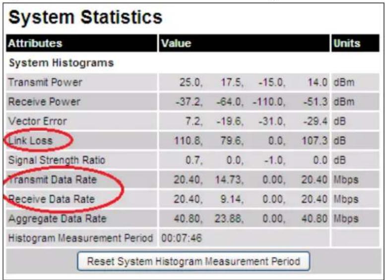
For more information on the System Statistics page, refer to System Statistics page on page 7-59.
Beam Steering ODU automatic alignment
This section describes how to align Beam Steering ODUs with Automatic Alignment enabled.
Hardware installation
Check that hardware installation of ODUs is complete, and that the integrated antennas have been approximately aligned using compass bearing or by reference to landmarks or other geographical features.
Ensure that the ODUs are powered up.
Management connection
Connect suitable management stations (typically laptops) to Master and Slave ODUs, as described in Connecting to the unit on page 6-4. Log into the local unit as described in Logging into the web interface on page 6-7.
Configure the ODUs for installation with automatic alignment
Use the Wireless Configuration page of the Installation Wizard to configure:
• Automatic Alignment = Enabled
- Null Steering Control = Enabled
• Installation Mode = Arm Without Tones
Confirm the configuration and reboot Master and Slave ODUs.
Automatic alignment
When the ODU is armed for installation with automatic alignment enabled, alignment proceeds as part of link establishment, as follows:
• The Master ODU transmits a downlink acquisition signal using the sector antenna pattern
- The Slave ODU detects the downlink acquisition signal and carries out a coarse beam scan to find the beam with the greatest receive signal strength.
- The Slave ODU then carries out a localized fine beam scan to refine the optimum antenna beam.
- The Slave ODU transmits an uplink acquisition signal.
- The Master ODU detects the uplink acquisition signal and carries out coarse and fine beam scans.
- The link is established using aligned antennas at Master and Slave, and transitions to the OFDM modulation, starting at BPSK 0.63 Single.
Monitor progress of the installation process using the Alignment Status control on the System Status web page.
Disarming the units
When antenna alignment is complete, use this procedure to disarm both units in the link in order to:
- Enable adaptive modulation.
• Fully enable spectrum management features (such as DSO, if configured).
• Clear unwanted installation information from the various systems statistics. - Store the link range for fast link acquisition on link drop.
- Enable higher data rates.

Note After 6 hours, the units will be disarmed automatically, provided that they are armed and that the link is up.
Procedure:
- Select menu option Installation. The Disarm Installation page is displayed (Figure 119).
- Click Disarm Installation Agent. The confirmation page is displayed (Figure 227).
Figure 227 Optional post-disarm configuration
Installation Disarmed
The installation agent has been successfully disarmed.
To complete the installation process it is recommended that you now visit the Configuration page and enter the link name and location description fields and optionally save a backup copy of the link configuration.
You may also wish to visit the Spectrum Management page and configure the wireless link channel utilization
Comparing actual to predicted performance
For at least one hour of operation after disarming, use this procedure to monitor the link to check that it is achieving predicted levels of performance. LINKPlanner provides the prediction in the form of an installation report.
Procedure:
-
Select menu option System > Statistics. The System Statistic page is displayed (Figure 228).
• Monitor the following attributes: -
Link Loss
- Transmit Data Rate
- Receive Data Rate
Figure 228 Statistics to be monitored after alignment

For more information on the System Statistics page, refer to System Statistics page on page 7-59.
Force Realignment
The menu item Beam Steering Antenna displays only on the PTP 45700 Beam Steer ODU.
Figure 229 Beam Steering Antenna page
Beam Steering Antenna
This page controls the configuration of beam steering antenna.
| Attributes | Value | Units |
| Automatic Alignment | Enabled | |
| Null Steering Control | Disabled | |
| Minimum Azimuth | -60 | degrees |
| Maximum Azimuth | 60 | degrees |
| Minimum Elevation | -15 | degrees |
| Maximum Elevation | 15 | degrees |
Force Realignment
Force realignment initiates the automatic alignment of the beam-steering antenna. The beam steering antenna will realign itself to point towards the peer radio.
Force Realignment
The alignment orientation saves in the data manager upon the completion of alignment for the first time after traversing the Installation Wizard and configuring the ODU. This is useful for fixed installations, but there are situations where operators transport and reinstall the ODUs at a different location or want to re-run the alignment to verify or optimize the link.
To initiate the automatic alignment of the beam-steering antenna, use the Force Realignment button on either or both Master and Slave beam-steer ODUs.
Automatic alignment at one end of a link
Beam Steering ODUs will normally be used in pairs, in a link where both ends have automatic alignment enabled, with installation as described in Beam Steering ODU automatic alignment. However, it is possible to create a link between one ODU with automatic alignment and one ODU with a fixed beam antenna. In this case, a modified installation procedure is required, as detailed below:
Automatic alignment at the Slave
1 Mechanically install Master and Slave ODUs with approximate alignment based on compass bearing or landmarks.
2 Arm the Master and Slave ODUs for installation.
3 The Slave ODU will search for the downlink acquisition signal and complete coarse and fine automatic alignment, and the link will establish with OFDM modulation (BPSK 0.63 Single).
4 Manually align the antenna at the Master ODU for maximum received signal strength.
5 Disarm installation at Master and Slave ODUs.
Automatic alignment at the Master
1 Mechanically install Master and Slave ODUs with approximate alignment based on compass bearing or landmarks.
2 Arm the Master and Slave ODUs for installation.
3 The Slave ODU will search for the downlink acquisition signal and transmit the uplink acquisition signal immediately.
4 The Master ODU will complete coarse and fine automatic alignment, and the link will establish with OFDM modulation (BPSK 0.63 Single).
5 Manually align the antenna at the Slave ODU for maximum received signal strength.
6 Disarm installation at Master and Slave ODUs.
Other configuration tasks
This section describes other configuration tasks.
Connecting to the network
Use this procedure to complete and test network connections.
Procedure:
1 If a management PC is connected directly to the PTP 700, disconnect it.
2 Confirm that all ODU Ethernet interface cables (PSU, SFP and Aux) are connected to the correct network terminating equipment or devices.
If Main PSU Port is not allocated to the Data or Management services, it is not necessary to connect the PSU LAN port to network terminating equipment.
3 Test that the unit is reachable from the network management system by opening the web interface to the management agent, or by requesting ICMP echo response packets using the Ping application. For in-band management, test that both units are reachable from one PC.
If the network management system is remote from the sites, either ask co-workers at the management center to perform this test, or use remote login to the management system.
4 Test the data network for correct operation across the wireless link. This may be by requesting ICMP echo response packets between hosts in the connected network segments, or by some more structured use of network testing tools.
5 Monitor the Ethernet ports and wireless link to confirm that they are running normally. For instructions, see System Summary page on page 7-2 and Standard System Status page on page 7-3.
Upgrading firmware using TFTP
Use this procedure to upgrade firmware remotely using Trivial FTP (TFTP) triggered by SNMP.
Procedure:
1 Check that the TFTP client is enabled. Refer to Web-Based Management page on page 6-83.
2 Set tFTP attributes as described in Table 211.
3 Monitor tFTP attributes as described in Table 212.
4 Reboot the ODU as described in Rebooting the unit on page 7-89.
Table 211 Setting tFTP attributes
| Attribute | Meaning |
| tFTPServerInternetAddress | The FQDN, IPv4 or IPv6 address of the TFTP server from which the TFTP software upgrade file Name will be retrieved.For example, to set the TFTP server IP address for the unit at 10.10.10.10 to the IPv4 address 10.10.10.1, enter this command:snmpset_d.exe -v 2c -c public 10.10.10.10.iso.3.6.1.4.1.17713.7.9.19.0 a 10.10.10.1 |
| tFTPServerPortNumber | This setting is optional. The port number of the TFTP server from which the TFTP firmware upgrade file name will be retrieved (default=69). |
| tFTPSoftwareUpgrade FileName | The filename of the firmware upgrade to be loaded from the TFTP server.For example, to set the TFTP firmware upgrade filename on 10.10.10.10 to "B1095.dld", enter this command:snmpset_d.exe -v 2c -c public 10.10.10.10.iso.3.6.1.4.1.17713.7.9.7.0 s B1095.dld |
| tFTPStartSoftware Upgrade | Write “1” to this attribute to start the TFTP firmware upgrade process. The attribute will be reset to 0 when the upgrade process has finished.For example, enter this command:snmpset_d.exe -v 2c -c public 10.10.10.10.iso.3.6.1.4.1.17713.7.9.8.0 i 1 |
Table 212 Monitoring tFTP attributes
| Attribute | Meaning |
| tFTPSoftwareUpgradeStatus | This is the current status of the TFTP firmware upgrade process. Values: idle(0) uploadinprogress(1) uploadsuccessfulprogrammingFLASH(2) upgradesuccessfulreboottorunthenewsoftwareimage(3) upgradefailed(4). For example, enter this command: snmpget_d.exe -v 2c -c public 10.10.10.10 .iso.3.6.1.4.1.17713.7.9.9.0 |
| tFTPSoftwareUpgradeStatus Text | This describes the status of the TFTP firmware upgrade process, including any error details. For example, enter this command: snmpget_d.exe -v 2c -c public 10.10.10.10 .iso.3.6.1.4.1.17713.7.9.10.0 |
| tFTPSoftwareUpgradeStatus AdditionalText | This is used if tFTPSoftwareUpgradeStatusText is full and there are more than 255 characters to report. It contains additional text describing the status of the TFTP firmware upgrade process, including any error details. For example, enter this command: snmpget_d.exe -v 2c -c public 10.10.10.10 .iso.3.6.1.4.1.17713.7.9.11.0 |
This chapter provides instructions for operators of the PTP 700 wireless Ethernet bridge.
The following topics are described in this chapter:
• System summary and status on page 7-2
• Rebooting and logging out on page 7-22
• Alarms, alerts and messages on page 7-24
• Spectrum Management on page 7-32
• Managing security on page 7-57
• System statistics on page 7-59
• Recovery mode on page 7-80.
System summary and status
This section describes how to use the summary and status pages to monitor the status of the Ethernet ports and wireless link.
System Summary page
Menu option: Home (Figure 230).
This page contains a high-level summary of the status of the wireless link and associated equipment.
Figure 230 System Summary page

Procedure:
• Review the attributes (Table 213).
- Check that the Wireless Link Status is "Up" on both units. If it is not "Up", review any uncleared system alarms: these are displayed below the System Clock attribute. For more information, refer to Alarms on page 7-24.
Table 213 System Summary attributes
| Attribute | Meaning |
| Wireless Link Status | Current status of the wireless link.A green background with status text “Up” means that the point-to-point link is established.A red background with suitable status text (for example “Searching”) indicates that the link is not established. |
| Link Name | The name of the PTP link, as set in the System Configuration page. |
| Elapsed Time Indicator | The time (hh:mm:ss) that has elapsed since the last system reboot.The system can reboot for several reasons, for example, commanded reboot from the system reboot webpage, or a power cycle of the equipment. |
| System Clock | The system clock presented as local time, allowing for zone and daylight saving (if set). |
Standard System Status page
PTP topology
Menu option: Status (Figure 231). This page provides a detailed view of the operation of the PTP 700 link, including identification, management, wireless and network interfaces.
Figure 231 System Status page (PTP topology)
| System Status - Point To Point - Master | ||
| Attributes | Value | Units |
| Equipment | ||
| Link Name | Bolinas Ridge to Mount Tamalpais | |
| Unit Name | Bolinas 6 | |
| Site Name | Bolinas Ridge | |
| Software Version | 45700-03-65 | |
| Hardware Version | BOP04.03-C-FPS | |
| Unit SKU | C045070B003B | |
| Unit ESN | 0004565800B8 | |
| Unit MSN | U9SD0B1ZP6J4 | |
| Regulatory Band | 95 - 4.5 GHz - Development Key | |
| Elapsed Time Indicator | 00:05:23 | |
| Ethernet / Internet | ||
| Main PSU Port Status | Copper Link Up | |
| Main PSU Port Speed And Duplex | 1000 Mbps Full Duplex | |
| MAC Address | 00:04:56:58:00:b8 | |
| Management | ||
| cnMaestro Server | cnMaestro On-Premises | |
| cnMaestro Connection Status | Connecting | |
| cnMaestro Connection Status Message | ||
| Remote Identification | ||
| Remote Unit Name | Tamalpais 2 | |
| Remote MAC Address | 00.04.56.58.00.a8 | |
| Remote Internet Address | http://10.130.159.48 | |
| TDD Synchronization | ||
| TDD Synchronization Interface | Disabled | |
| Status Page Refresh Period | 3 Seconds | |
In the PTP topology, the two PTP 700 Series units are arranged in a master and slave relationship. The roles of the units in this relationship are displayed in the page title. The master unit will always have the title “- Master”, and the slave will always have “- Slave” appended to the “Systems Status” page title.
Automatic Alignment
When a Beam Steering ODU is used with Automatic Alignment enabled, the Wireless section of the System Status page displays additional controls, as shown in Figure 232.
Figure 232 System Status page (Wireless section, PTP topology, Automatic Alignment enabled)
| Attributes | Value | Units |
| Wireless | ||
| Wireless Link Status | Up | |
| Wireless Link Up Time | 08:18:48 | |
| Wireless Encryption | None | |
| Data Bridging Status | Enabled | |
| Transmit Frequency | 4420 | MHz |
| Receive Frequency | 4420 | MHz |
| Maximum Transmit Power | -10 | dBm |
| Alignment Status | Pre Aligned | |
| Beam Azimuth | -3 | degrees |
| Beam Elevation | 1 | degrees |
| EIRP | 11.0 | dBm |
| Remote Maximum Transmit Power | -10 | dBm |

Note Link Symmetry is configured at the master ODU only. The appropriate matching Link Symmetry is set at the slave ODU automatically. For example, if Link Symmetry is configured as 2 to 1 at the master ODU, then the slave ODU will be set automatically as 1 to 2. In this example, the master-slave direction has double the capacity of the slave-master direction.
HCMP topology
Menu option: Status (Figure 233 to Figure 235). This page provides a detailed view of the operation of the PTP 700 link including identification, management, wireless and network interfaces.
Figure 233 System Status page (Master, HCMP topology, Wireless Interface set to a single link)

Figure 234 System Status page (Master, HCMP topology, Wireless Interface set to "All Wireless Interfaces")
| System Status - High Capacity Multi-Point - Master | ||||
| Attributes | Value | Units | ||
| Wireless Interface Selector | All Wireless Interfaces ▼ | |||
| Attributes | Value | Value | Value | Units |
| Equipment | ||||
| Unit Name | Master_AJ | |||
| Site Name | ||||
| Software Version | 45700-G7PFP-B40+ wdog | |||
| Hardware Version | BOP05.01-C-FPS | |||
| Unit ESN | 000456580262 | |||
| Unit MSN | 2249RS0566 | |||
| Regulatory Band | 81 - 4.7 GHz - Development Key | |||
| Elapsed Time Indicator | 01:13:47 | |||
| TDD Synchronization | ||||
| TDD Synchronization Status | Not Synchronized (No GPS/Sync In) | |||
| Ethernet / Internet | ||||
| Main PSU Port Status | Copper Link Up | |||
| Main PSU Port Speed And Duplex | 1000 Mbps Full Duplex | |||
| Group ID | 0 | |||
| MAC Address | 00:04:56:58:02:62 | |||
| Remote MAC Address | 00:04:56:58:01:d5 | Not Available | Not Available | |
| Remote Internet Address | http://10.10.10.11 | Not Available | Not Available | |
| Wireless | ||||
| Remote Unit Name | Slave_58_01_D5 | Not Available | Not Available | |
| Wireless Link Status | Up | Initialising | Searching | |
| Wireless Encryption | AES 256-bit TLS RSA | None | None | |
| Maximum Transmit Power | 28 | dBm | ||
| Remote Maximum Transmit Power | 28 | Not Available | Not Available | dBm |
| Transmit Power | 23.0, 23.0 | 28.0, 28.0 | 0.0, 0.0 | dBm |
| Receive Power | -46.2, -46.2 | -109.9, -110.0 | 0.0, 0.0 | dBm |
| Vector Error | -35.5, -36.6 | 0.0, 0.0 | 0.0, 0.0 | dB |
| Link Loss | 67.2, 67.2 | 0.0, 0.0 | 0.0, 0.0 | dB |
| Transmit Data Rate | 57.89, 57.89 | 0.00, 0.00 | 0.00, 0.00 | Mbps |
| Receive Data Rate | 2.78, 2.78 | 0.00, 0.00 | 0.00, 0.00 | Mbps |
| Link Capacity | 60.68 | 0.00 | 0.00 | Mbps |
| Transmit Modulation Mode | 256QAM 0.81 (Dual) | Acquisition | Acquisition | |
| Receive Modulation Mode | BPSK 0.63 | Acquisition | Acquisition | |
| Channel Bandwidth | 40 MHz | |||
| Range | 0.2 | Not Available | 0.0 | km |
| Status Page Refresh Period | 3600 | seconds | ||
Figure 235 System Status page (Slave, HCMP topology)
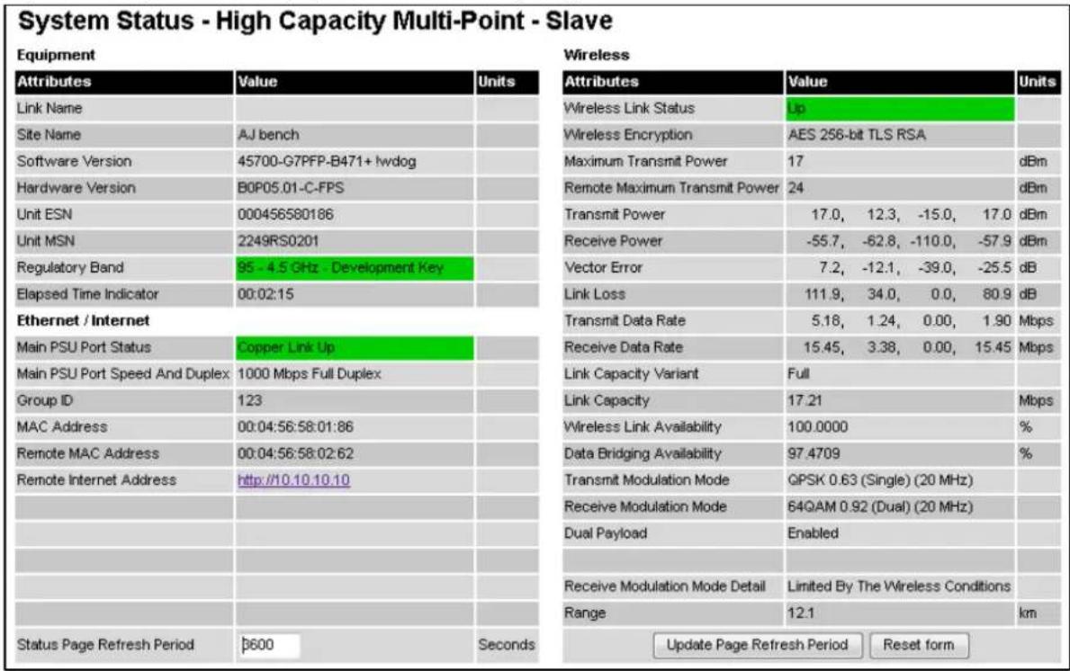
In the HCMP topology, one PTP 700 Series unit is the Master and up to eight PTP 700 Series units are configured as Slaves. The roles of the units in this relationship are displayed in the page title. The master unit will always have the title “- High Capacity MultiPoint - Master”, and the slave will always have “- High Capacity MultiPoint - Slave” appended to the “Systems Status” page title.
Procedures:
- Only on a device configured as in HCMP mode as a Master, set the Wireless Interface Selector to the Wireless Interface the diagnostic data needs to be displayed for. Note the Remote MAC Address indicates the MAC address of the unit currently connected, if any, to the selected wireless interface.
Equipment
The Equipment section of the System Status page contains the attributes described in Table 214.
Table 214 System Status attributes - Equipment
| Attribute | Meaning |
| Link Name | The link name is allocated by the system administrator and is used to identify the equipment on the network. The link name attribute is limited to a maximum size of 63 ASCII characters. |
| Site Name | The site name is allocated by the system administrator and can be used as a generic scratch pad to describe the location of the equipment or any other equipment related notes. The site name attribute is limited to a maximum size of 63 ASCII characters. |
| Software Version | The version of PTP 700 firmware installed on the equipment. |
| Hardware Version | The PTP 700 hardware version. Formatted as “vvvv-l”, “vvvv-C” or “vvvv-C+I” where vvvv is the version of the printed circuit card. The “-I” suffix indicates a PTP 700 Integrated unit. The “-C” suffix indicates a PTP 700 Connectorized unit. The “-C+I” suffix indicates a PTP 700 Connectorized+Integrated unit. |
| Unit ESN | The Electronic Serial Number of the ODU. |
| Unit MSN | The Mechanical Serial Number of the ODU. |
| Unit SKU | The Cambium Part Number of the ODU |
| Unit Color | White, Green, Desert TanThe color of the external paint finish of the ODU. |
| Regulatory Band | This is used by the system to constrain the wireless to operate within regulatory regime of a particular band and country. The license key provides the capability to operate in one or more regulatory bands. The Installation Wizard is used to choose one of those bands. |
| Elapsed Time Indicator | The elapsed time indicator attribute presents the total time in years, days, hours, minutes and seconds since the last system restart. The system can restart for several reasons, for example commanded reboot from the system reboot web page, or a power cycle of the equipment. |
Ethernet / Internet
The Ethernet / Internet section of the System Status page contains the attributes described in Table 215.
Table 215 System Status attributes - Ethernet / Internet
| Attribute | Meaning |
| Main PSU Port Status | The current status of the Ethernet link to the PSU port:Green “Copper Link Up”: The Ethernet link is established.Red “Down”: The Ethernet link is not established. |
| Main PSU Port Speed and Duplex | The negotiated speed and duplex setting of the Ethernet link to the PSU port. The speed setting is specified in Mbps. |
| Aux Port Status | The current status of the Ethernet link to the Aux port:Green “Copper Link Up”: The Ethernet link is established.Red “Down”: The Ethernet link is not established. |
| Aux Port Speed and Duplex | The negotiated speed and duplex setting of the Ethernet link to the Aux port. The speed setting is specified in Mbps. |
| SFP Port Status | The current status of the Ethernet link to the SFP port:Green “Fiber Link Up”: The Ethernet link is established.Red “Down”: The Ethernet link is not established. |
| SFP Port Speed and Duplex | The negotiated speed and duplex setting of the Ethernet link to the SFP port. The speed setting is specified in Mbps. |
| MAC Address | The MAC Address of this unit. |
Management
The Management section of the System Status page contains the attributes described in Table 216.
Table 216 System Status attributes - Management
| Attribute | Meaning |
| cnMaestro Server | cnMaestro On-Premises: The ODU will connect to the On Premises server.cnMaestro Cloud: The ODU will connect to the Cloud server. |
| cnMaestro Connection Status | The status of the connection between the ODU and the cnMaestro server-connected: The ODU is connected to the cnMaestro Server.Not Connected: The ODU is not connected to the cnMaestro Server. This is default state in which transactions begin.DNS Failed: The ODU could not resolve the supplied cnMaestro Server Internet Address.Error returned by Server: An error occurred on the server. The cnMaestro Connection Status Message attribute will display the details.Connecting: Connection is in progress. The ODU is communicating with the cnMaestro Server.Approval Pending: A connection has been established. The ODU is in cnMaestro Server's On-boarding queue, waiting for a cnMaestro user to approve the ODU as a new device. After the device is approved, the ODU should transition to the Connected state.Ownership Error: The cnMaestro server is unable to match the supplied Cambium ID or Onboarding Key with its configured data. |
| cnMaestro Connection Status Message | Error text generated by the cnMaestro server when an error is returned. |
Remote Identification
The Remote Identification section of the System Status page contains the attributes described in Table 217.
Table 217 System Status attributes - Remote Identification
| Attribute | Meaning |
| Remote Unit Name | The configured Unit Name of the peer unit. If the link is down, this is set to “Not available”. |
| Remote MAC Address | The MAC Address of the peer unit. If the link is down, this is set to “Not available”. |
| Remote Internet Address | The Internet Address of the peer unit. To open the web interface of the peer unit, click on the hyperlink. If the link is down, this is set to “Not available”.Depending on the settings of IP Version (Table 177) and IP Address Label (Table 176), this may be either an IPv4 or an IPv6 address. |
Protection
The Protection section of the System Status page contains the attributes described in Table 218.
Table 218 System Status attributes - Protection
| Attribute | Meaning |
| Protection State | Unprotected: The Primary and/or Secondary link is not available, and so the Hot Standby system is not protecting the end-to-end connection. |
| Hot Standby Link State | Standby: The ODU is part of a wireless link in the Standby state. This may be because the link has a fault and is therefore unavailable, or because the link is fault-free, but neighbor link is in the Active state.Active: The ODU is in a wireless link in the Active state. The link is fault-free and is forwarding traffic in the Data and Management services. |
Wireless
The Wireless section of the System Status page contains the attributes described in Table 219.
Table 219 System Status attributes - Wireless
| Attribute | Meaning |
| Wireless Link Status | The current status of the wireless link:Green “Up”: The wireless link is established.Red “Down”: The wireless link is not established. |
| Wireless Link Up Time | The time in hours, minutes, seconds that the present wireless link has been established. |
| Wireless Encryption | For the HCMP topology only, the encryption algorithm used for the wireless link:None: The wireless link in not encrypted.AES 128-bit TLS RSA: The wireless link in encrypted using the AES TLS RSA algorithm with a 128-bit key.AES 256-bit TLS RSA: The wireless link in encrypted using the AES TLS RSA algorithm with a 256-bit key. |
| Data Bridging Status | Enabled: The link is bridging Ethernet frames.Blocked By Protection: The link is not bridging Ethernet frames because it is in the Standby state as part of a Hot Standby system.Disabled: The link is not bridging Ethernet frames because the Lowest Data Modulation Mode is not being achieved. |
| Transmit Frequency | The radio frequency of the transmit radio channel (MHz). |
| Receive Frequency | The radio frequency of the receive radio channel (MHz). |
| Maximum Transmit Power | The maximum transmit power that the local wireless unit is permitted to use to sustain a link. |
| Alignment Status | Displayed in a Beam Steering ODU with Automatic Alignment enabled.Initializing: The ODU is preparing for installation with automatic alignment.Sector: The ODU is receiving using the sector antenna pattern.Coarse Scan: The ODU is receiving using the direction pattern and scanning to find the coarse beam position with the largest received signal strength.Fine Scan: The ODU is receiving using the direction pattern and scanning to find the fine beam position with the largest received signal strength.Complete: Installation with automatic alignment is complete.Pre Aligned: The ODU has applied azimuth and elevation values determined in an earlier installation. |
| Beam Azimuth | Displayed in a Beam Steering ODU with Automatic Alignment enabled.The azimuth angle of the selected antenna beam (in degrees) relative to the centre of the antenna coverage. |
| Beam Elevation | Displayed in a Beam Steering ODU with Automatic Alignment enabled.The elevation angle of the selected antenna beam (in degrees) relative to the centre of the antenna coverage. |
| EIRP | The effective isotropic radiated power of the ODU (dBm), based on Transmit Power, Cable Loss and Antenna Gain. |
| Remote Maximum Transmit Power | The maximum transmit power that the remote wireless unit is permitted to use to sustain a link. |
| Transmit Power | The maximum, mean, minimum and latest measurements of Transmit Power (dBm). SeeSystem histogramson page 7-59. |
| Receive Power | The maximum, mean, minimum and latest measurements of Receive Power (dBm). SeeSystem histogramson page 7-59. |
| Vector Error | The maximum, mean, minimum and latest measurements of Vector Error (dB). SeeSystem histogramson page 7-59.Vector Error compares the received signals In phase / Quadrature (IQ) modulation characteristics to an ideal signal to determine the composite error vector magnitude. The expected range for Vector Error is approximately -2 dB (NLOS link operating at sensitivity limit on BPSK 0.67) to -33 dB (short LOS link running 256 QAM 0.81). |
| Link Loss | The maximum, mean, minimum and latest measurements of Link Loss (dB). SeeSystem histogramson page 7-59. The link loss is the total attenuation of the wireless signal between the two point-to-point units. The link loss calculation is: CRRxCCP Where: Pll = Link Loss (dB) PTx = Transmit power of the remote wireless unit (dBm) PRx = Received signal power at the local unit (dBm) gTx, gRx = Antenna gain at the remote and local units respectively (dBi). This is the gain of the integrated or connectorized antenna. cTx, cRx = Cable loss at the remote and local units respectively (dB). It is RF cable loss which connects ODU to Connectorized antenna. For connectorized ODUs, the link loss calculation is modified to allow for the increased antenna gains at each end of the link. |
| Transmit Data Rate | The maximum, mean, minimum and latest measurements of Transmit Data Rate (Mbps). SeeSystem histogramson page 7-59. |
| Receive Data Rate | The maximum, mean, minimum and latest measurements of Receive Data Rate (Mbps). SeeSystem histogramson page 7-59. |
| Link Capacity Variant | Indicates the licensed capacity from the License Key. Link Capacity Variant is one of the following:FullLiteWhen a link is established, this attribute shows the lower of the licensed capacity at each end. For example, if this end is Full and the other end is Lite, it shows “Lite”. To see the licenses in the installed License Key, go to the Installation Wizard. |
| Link Capacity | The maximum aggregate data rate capacity available for user traffic, assuming the units have been connected using Gigabit Ethernet. The link capacity is variable and depends on the prevailing wireless conditions as well as the distance (range) between the two wireless units. |
| Transmit Modulation Mode | The modulation mode currently being used on the transmit channel. |
| Receive Modulation Mode | The modulation mode currently being used on the receive channel. |
| Link Symmetry | A ratio that expresses the division between transmit and receive time in the TDD frame. The first number in the ratio represents the time allowed for the transmit direction and the second number represents the time allowed for the receive direction. |
| Receive Modulation Mode Detail | The receive modulation mode in use. For a list of values and their meanings, see Table 220. |
| Range | The range between the PTP 700 Series ODUs. This is displayed in kilometers by default, but can be changed to miles by updating the Distance Units attribute to imperial, as described in Webpage Properties page on page 6-92. |
Table 220 Receive Modulation Mode Detail values and meanings
| Value | Meaning |
| Running At Maximum Receive Mode | The link is operating at maximum modulation mode in this channel and maximum throughput has been obtained. |
| Running At User-Configured Max Modulation Mode | The maximum modulation mode has been capped by the user and the link is operating at this cap. |
| Restricted Because Installation Is Armed | The Installation Wizard has been run and the unit is armed, forcing the link to operate in the lowest modulation mode. To remove this restriction, re-run the Installation Wizard to disarm the unit. |
| Restricted Because Of Byte Errors On The Wireless Link | The receiver has detected data errors on the radio and reduced the modulation mode accordingly. The radio may achieve a higher modulation mode as shown by the vector error, but there is some other error source, probably RF interference. |
| Restricted Because Channel Change Is In Progress | This is a transient event where the modulation mode is temporarily reduced during a channel change. |
| Limited By The Wireless Conditions | The radio is running at the maximum achievable modulation mode given the current wireless conditions shown by the vector error. The radio is capable of reaching a higher modulation mode if wireless conditions (vector error) improve. |
Synchronous Ethernet

Note Synchronous Ethernet is available in the PTP topology.
The Synchronous Ethernet section of the System Status page contains the attributes described in Table 221.
Table 221 System Status attributes - Synchronous Ethernet
| Attribute | Meaning |
| Sync E Tracking State | The state of frequency tracking in Synchronous Ethernet. For a list of values and their meanings, see Table 222.In normal operation, with the Synchronous Ethernet feature enabled and a valid timing source present, one end of the link should be in the “Locked Local, Holdover Acquired State”, the other end should be in the “Locked Remote, Holdover Acquired” state.Further status information for the Synchronous Ethernet features is available in the Sync E Status page. See SyncE Status page on page 7-73. |
Table 222 Sync E Tracking State values and meanings
| Value | Meaning |
| Disabled | The synchronous Ethernet feature is disabled. |
| Acquiring Wireless Lock | Synchronous Ethernet is not operational because the wireless link is establishing. |
| Free Running | Synchronous Ethernet is operational, but with no timing source or history. This is a temporary state. |
| Locked Local, Acquiring Holdover | Sync E tracking has locked to a synchronisation signal from a cabled Ethernet port on the local ODU. This is a temporary state until the unit has acquired holdover history. |
| Locked Local, Holdover Acquired | Sync E tracking has locked to a synchronisation signal from a cabled Ethernet port on the local ODU and has acquired holdover history. |
| Holdover | There is currently no source for the tracking loop, but previously the tracking loop was in a Locked, Holdover Acquired state. The system is using the last known good frequency. |
| Locked Remote, Acquiring Holdover | The tracking loop has locked to a synchronisation signal from the remote ODU. This is a temporary state until the unit has acquired holdover history. |
| Locked Remote, Holdover Acquired | The tracking loop has locked to a synchronisation signal form the remote ODU and has acquired holdover history. |
TDD Synchronization
The TDD Synchronization section of the System Status page contains the attributes described in Table 223.
Table 223 System Status attributes - TDD Synchronization
| Attribute | Meaning |
| TDD Synchronization Status | The status of TDD synchronization. Displayed at a TDD Master if TDD synchronization is active. For a list of values and their meanings, see Table 224 and Table 225. |
Table 224 TDD Synchronization Status values and meanings for PTP-SYNC
| Value | Meaning |
| Inactive | TDD Synchronization has been administratively disabled.This value is not displayed in the System Status page, but can be determined from the SNMP MIB.TDD Synchronization Status is always in the Inactive state at a TDD Slave unit. |
| Cluster Timing Master | The ODU has been configured as a Cluster Master with an internal reference, and is communicating correctly with the PTP SYNC unit. |
| Initialising | The wireless link is down, and the master ODU is attempting to synchronize the TDD frame structure with an external 1 pps reference.Synchronization proceeds more rapidly in this state than in the Acquiring Lock state, because the TDD master does not need to consider the ability of the TDD slave to track changes in frame timing. |
| PTP-SYNC Not Connected | The ODU is not able to communicate with the PTP SYNC unit. |
| Locked | The master ODU has locked the TDD frame structure to the 1 pps reference received at the Configure of the PTP-SYNC unit.The ODU may be a Cluster Master or a Cluster Slave.The ODU is transmitting. |
| Holdover (No GPS Sync In) | The 1 pps reference has been lost at the Configure to the PTP-SYNC unit, and the ODU in a free running state.The ODU is transmitting.If the reference Configure is not restored, the Holdover state will terminate automatically after a period set by TDD Holdover Duration. |
| Holdover | The ODU is a Cluster Slave and the 1 pps reference has been lost at the Configure to an upstream PTP-SYNC unit. The ODU is locked to an upstream ODU that is in the Holdover (No GPS Sync In) state.The ODU is transmitting.If the reference Configure is not restored at the upstream PTP-SYNC unit, the Holdover state will terminate automatically after a period set by TDD Holdover Duration. |
| Not Synchronized (No GPS Sync In) | The 1 pps reference has been lost at the Configure to the PTP-SYNC unit and the holdover period has expired.If the ODU is configured for TDD Holdover Mode = Best Effort then the ODU will be transmitting, otherwise it will be muted. |
| Not Synchronized | The ODU is a Cluster Slave and the 1 pps reference has been lost at the Configure to an upstream PTP-SYNC unit. The holdover period has expired.If the ODU is configured for TDD Holdover Mode = Best Effort then the ODU will be transmitting, otherwise it will be muted. |
| Acquiring Lock | The wireless link is up and the master ODU is attempting to synchronize the TDD frame structure with an external 1 pps reference. Frame timing changes at the TDD master are constrained to allow for tracking by the TDD slave.This state is not allowed when TDD Holdover Mode = Strict. |
Table 225 TDD Synchronization Status values and meanings for direct connection
| Value | Meaning |
| Inactive | TDD Synchronization has been administratively disabled.This value is not displayed in the System Status page, but can be determined from the SNMP MIB.TDD Synchronization Status is always in the Inactive state at a TDD Slave unit. |
| Initialising | The wireless link is down, and the master ODU is attempting to synchronize the TDD frame structure with an external 1 pps reference. Synchronization proceeds rapidly in this state because the TDD master does not need to consider the ability of the TDD slave to track changes in frame timing. |
| Locked | The TDD frame structure is locked to a 1 pps reference from the directly-connected partner ODU. The ODU is transmitting. |
| Holdover | The ODU is transmitting. If the reference Configure is not restored, the Holdover state will terminate automatically after a period set by TDD Holdover Duration. |
| Not Synchronized | The holdover period has expired. If the ODU is configured for TDD Holdover Mode = Best Effort then the ODU will be transmitting, otherwise it will be muted. |
IEEE 1588 Transparent Clock

Note IEEE 1588 Transparent Clock is available in the PTP topology.
The IEEE 1588 Transparent Clock section of the System Status page contains the attributes described in Table 226.
Table 226 System Status attributes - IEEE 1588 Transparent Clock
| Attribute | Meaning |
| Transparent Clock | Indicates if the IEEE 1588 transparent clock feature is enabled. |
Simplified System Status page
Menu option: Status (Figure 236 and Figure 237). This page provides a simplified view of the operation of the PTP 700 link from both the wireless and network perspectives.
Figure 236 System Status page (Simplified web interface)

In the PTP topology, the two PTP 700 Series units are arranged in a master and slave relationship. The roles of the units in this relationship are displayed in the page title. The master unit will always have the title "- Master", and the slave will always have "- Slave" appended to the "Systems Status" page title.
Figure 237 System Status page (HCMP Master, Simplified web interface)
| System Status - High Capacity Multi-Point - Master | ||
| Attributes | Value | Units |
| ODU | ||
| System Clock | 01-Jan-1970 00:00:00 | |
| Main PSU Port Status | Copper Link Up | |
| Channel Bandwidth | 40 MHz | |
| Transmit Power | 23.0 | dBm |
| Transmit Frequency | 6000 | MHz |
| Receive Frequency | 6000 | MHz |
| Wireless link #1 | ||
| Remote Unit Name | HCMP4_Link1_670_Slave_12 | |
| Wireless Link Status | Up | |
| Wireless Encryption | None | |
| Receive Power | -56.4 | dBm |
| Vector Error | -30.8 | dB |
| Transmit Data Rate | 40.43 | Mbps |
| Receive Data Rate | 3.89 | Mbps |
| Range | 0.1 | km |
| Remote Internet Address | http://10.110.230.12 | |
| Wireless link #2 | ||
| Remote Unit Name | HCMP4_Link1_670_Slave_15 | |
| Wireless Link Status | Up | |
| Wireless Encryption | None | |
| Receive Power | -56.8 | dBm |
| Vector Error | -31.3 | dB |
| Transmit Data Rate | 40.43 | Mbps |
| Receive Data Rate | 3.89 | Mbps |
| Range | 0.1 | km |
| Remote Internet Address | http://10.110.230.15 | |
In the HCMP topology, one PTP 700 Series unit is the Master and up to eight PTP 700 Series units are configured as Slaves. The roles of the units in this relationship are displayed in the page title. The master unit will always have the title “- High Capacity MultiPoint - Master”, and the slave will always have “- High Capacity MultiPoint - Slave” appended to the “Systems Status” page title.
ODU
The ODU section of the System Status page contains the attributes described in Table 227.
Table 227 System Status attributes - Equipment
| Attribute | Meaning |
| System Clock | The system clock presented as local time, allowing for zone and daylight saving (if set). |
| Main PSU Port Status | The current status of the Ethernet link to the PSU port:• Green Copper Link Up: The Ethernet link is established.• Red Down: The Ethernet link is not established. |
| Channel Bandwidth | Bandwidth of the transmit and receive radio channels. |
| Transmit Power | The latest measurement of Transmit Power (dBm). |
| Transmit Frequency | The radio frequency of the transmit radio channel (MHz). |
| Receive Frequency | The radio frequency of the receive radio channel (MHz). |
Wireless
The Wireless section of the System Status page contains the attributes described in Table 228. At a Master ODU in the HCMP topology, this section is repeated for each of the wireless links.
Table 228 System Status attributes - Wireless
| Attribute | Meaning |
| Remote Unit Name | The configured Unit Name of the peer unit. If the link is down, this is set to Not available. |
| Wireless Link Status | The current status of the wireless link:Green Up: The wireless link is established.Red Down: The wireless link is not established. |
| Wireless Encryption | The encryption algorithm used for the wireless link:None: The wireless link in not encrypted.AES 128-bit TLS RSA: The wireless link in encrypted using the AES TLS RSA algorithm with a 128-bit key.AES 256-bit TLS RSA: The wireless link in encrypted using the AES TLS RSA algorithm with a 256-bit key.AES 128-bit TLS PSK: The wireless link in encrypted using the AES TLS PSK algorithm with a 128-bit key.AES 256-bit TLS PSK: The wireless link in encrypted using the AES TLS PSK algorithm with a 256-bit key. |
| Receive Power | The latest measurement of Receive Power (dBm). |
| Vector Error | The latest measurement of Vector Error (dB). |
| Transmit Data Rate | The latest measurement of Transmit Data Rate (Mbps). |
| Receive Data Rate | The latest measurement of Receive Data Rate (Mbps). |
| Range | The range between the PTP 700 Series ODUs, displayed in kilometers. |
| Remote Internet Address | The IPv4 Internet Address of the peer unit. To open the web interface of the peer unit, click on the hyperlink. If the link is down, this is set to Not available. |
Alarms
In the simplified web interface, active alarms are displayed on the System Status page. The alarms are identical to alarms displayed in the standard web interface, and are listed in Table 229 on page 7-24.
Rebooting and logging out
This section describes how to reboot the unit and log out of the web interface.
Login Information page
Menu option: Management > Web > Login Information (Figure 238).
Use this page to show recent successful and unsuccessful login attempts on this account.
Figure 238 Login Information page
| Login Information | ||
| This page shows details of recent successful and unsuccessful login attempts on this account. | ||
| Login Information for the System Administrator | ||
| Attributes | Value | Units |
| Successful login | ||
| Elapsed Time Since The Last Successful Login Attempt | 00:00:05 | |
| Internet Address Of Last Login | 169.254.1.3 | |
| Unsuccessful login attempts | ||
| Number Of Unsuccessful Login Attempts | 1 | |
| New Unsuccessful Login Attempts | 0 | |
| Elapsed Time Since The Last Unsuccessful Login Attempt | 00:00:07 | |
| Internet Address Of Last Unsuccessful Login Attempt | 169.254.1.3 | |
Reboot Wireless Unit page
Menu option: System > Reboot (Figure 239).
Use this page to reboot the ODU or view a list of previous reboot reasons.
Figure 239 Reboot Wireless Unit page
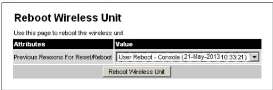
Procedure:
• Use the drop-down list to view the Previous Reasons For Reset/Reboot.
- If a reboot is required:
- Click Reboot Wireless Unit. The Reboot Confirmation dialog is displayed (Figure 240).
- Click OK. The reboot progress message is displayed. On completion, the unit restarts.
Figure 240 Reboot confirmation pop up

Change Password page
Menu option: Change Password (Figure 241). Use this page to change a personal password.
Figure 241 Change Password page (System Administration example)

A security officer can change the passwords of other users using the User Accounts page, as described in Local User Accounts page on page 6-85.
Procedure:
- Enter and confirm the new password. If Identity Based User Accounts is Disabled, the new password must be between eight and 31 characters. If Identity Based User Accounts is Enabled, the new password must comply with the complexity rules (Table 189).
Logging out
To maintain security, always log out at the end of a session: on the menu, click Logout.
The unit will log out automatically if there is no user activity for a set time, configured as Auto Logout Period in the Local User Accounts page (Figure 169 and Figure 170).
All sessions are automatically logged out after Web Absolute Timeout, regardless of user activity.
Alarms, alerts and messages
This section describes how to use alarms, alerts and syslog messages to monitor the status of a PTP 700 link.
Alarms
Whenever system alarms are outstanding, a yellow warning triangle is displayed on the navigation bar. The warning triangle is visible from all web pages.
Procedure:
- Click the warning triangle or the menu option Alarms to navigate to the Alarms page. The warning triangle and the Alarms menu item are hidden if there are no active alarms.
The example in Figure 242 shows the warning triangle in the navigation bar and an alarm displayed in the Alarms page. The alarms are defined in Table 229.
A change of state in most alarms generates an SNMP trap or an SMTP email alert.
Figure 242 Alarms page
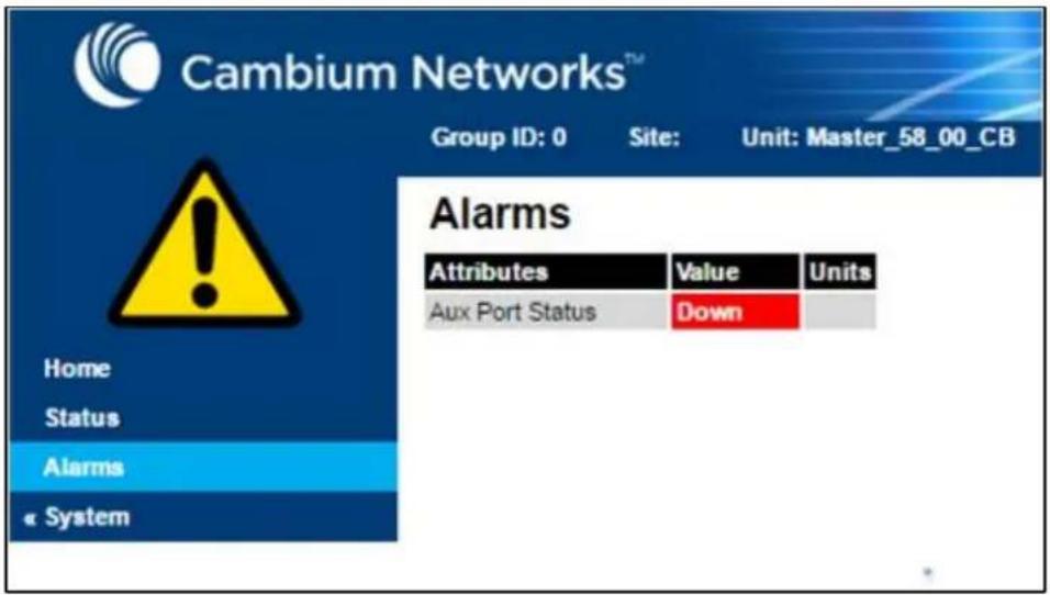
Table 229 System alarms
| Alarm | Meaning |
| Aux Port Configuration Mismatch | Ethernet fragments (runt packets) have been detected when the Aux port is in full duplex. This indicates an auto-negotiation or forced configuration mismatch. |
| Aux Port Disabled Warning | The Aux port link has been administratively disabled via the SNMP Interface. |
| Aux Port PoE Output Status | The Aux port link is down. The most likely cause is that the unit has no Ethernet cable plugged into its Aux port. |
| Aux Port Status | The Aux port link is down. The most likely cause is that the unit has no Ethernet cable plugged into its Aux port. |
| Cable Diagnostics Warning | “Test In Progress” means that the Cable Diagnostics test has been initiated on one or more ports and is in progress. |
| Capacity Variant Mismatch | The link ends are different capability variants, for example, one is Full and the other is Lite. |
| Data Bridging Status | Enabled: The link is bridging Ethernet framesBlocked By Protection: The link is not bridging Ethernet frames because it is in the Standby state as part of a Hot Standby system.Disabled: The link is not bridging Ethernet frames because the Lowest Data Modulation Mode is not being achieved. |
| Device Certificate Status | Please contact customer support if this error is displayed. |
| Hot Standby Configuration Check | The configuration of the ODU is not compatible with the configuration of a Hot Standby neighbor. |
| Hot Standby Neighbor Link Status | The neighbor link in a Hot Standby configuration has a fault, or its status is unknown. Possible values are “Unknown”, “Wireless Link Down”, “Master Data Port Down”, “Slave Data Port Down”. |
| Install Status | Signaling was received with the wrong MAC address. It is very unusual to detect this, because units with wrongly configured Target MAC Address will normally fail to establish a wireless link. However, rare circumstances may establish a partial wireless link and detect this situation. |
| Install Arm State | A wireless unit is in installation mode. After installation, the wireless unit should be disarmed. This will increase the data-carrying capacity and stop the installation tone generator. The wireless link is disarmed from the “Installation” process, see Disarming the units on page 6-148. |
| Incompatible Regulatory Bands | The two linked units have different Regulatory Bands. To clear this alarm, obtain and install license keys for the correct country and select the same Regulatory Band at each end of the link. |
| Incompatible Master and Slave | The master and slave ends of the wireless link are different hardware products, or have different firmware versions. It is very unusual to detect this because incompatible units will normally fail to establish a wireless link. However, some combinations may establish a partial wireless link and detect this situation. |
| Link Mode Optimization Mismatch | The Master and Slave ODUs are configured to use different link mode optimization methods (one is set to IP and the other TDM). |
| Main PSU Port Configuration Mismatch | Ethernet fragments (runt packets) have been detected when the PSU port is in full duplex. This indicates an auto-negotiation or forced configuration mismatch. |
| Main PSU Port Disabled Warning | The PSU port link has been administratively disabled via the SNMP Interface. |
| Main PSU Port Status | The PSU port link is down. The most likely cause is that the unit has no Ethernet cable plugged into its Aux port. |
| No Wireless Channel Available | Spectrum Management was unable to locate a suitable wireless channel to operate on. |
| Port Allocation Mismatch | The local and remote ODUs have different services configured. The following alarms are raised on the port configuration mismatch:Mismatch in Out of Band Remote Management Service:The Out of Band Management Service is configured at the local unit but it is not configured at the remote unit or vice versa. |
| Regulatory Band | The installed license key contains an invalid Regulatory Band. The wireless unit is prohibited from operating outside the regulated limits. |
| Remaining Full Capacity Time Trial | Time remaining on the full capability trial period. Activated when seven days or less of the trial period remain. |
| Remote Transparent Clock Compatibility | The local and remote units have different IEEE 1588 transparent clock configurations. Both units must have the same configuration for the feature to work correctly. |
| Secure Mode Alarm | The unit is operating in the FIPS secure mode, but is not in the operational state. To clear an alarm value of Secure mode is not configured ensure that all settings are correct for FIPS 140-3 in the Security Wizard. To clear an alarm value of Secure mode is configured, but not active ensure that HTTP Access Enabled is set to No. |
| SFP Error | A non-OK value indicates that the SFP link is down. There are two possible causes:Either: the fiber link has been installed but disabled (because the license key does not include SFP support),Or: the SFP link could not be established even though an SFP carrier was detected (due perhaps to a cabling fault or the link is disabled at the link partner). |
| SFP Port Configuration Mismatch | Ethernet fragments (runt packets) have been detected when the SFP port is in full duplex. This indicates an auto-negotiation or forced configuration mismatch. |
| SFP Port Disabled Warning | The SFP port link has been administratively disabled via the SNMP Interface. |
| SFP Port Status | The SFP port link is down. The most likely cause is that the unit has no Ethernet cable plugged into its SFP port. |
| SNTP Synchronization failed | SNTP has been enabled but the unit is unable to synchronize with the specified SNTP server. |
| Sync E tracking state | The state of the Synchronous Ethernet feature, if there is a problem. |
| Syslog Client Enabled/Disabled Warning | The local syslog client has been enabled or disabled. |
| Syslog Enabled/ Disabled Warning | The local log of event messages has been enabled or disabled. |
| Syslog Local Nearly Full | The local log of event messages is nearly full. |
| Syslog Local Wrapped | The local log of event messages is full and is now being overwritten by new messages. |
| TDD Synchronization Alarm | The reference signal for TDD Synchronization is absent and the ODU is now in holdover with more than 80% of the holdover period elapsed (Reference Signal Lost) or the ODU has reached the end of the configured holdover period and may not be correctly synchronized with the remaining units in the wireless network (Synchronization Lost).If TDD Synchronization Alarm = Synchronization Lost and TDD Holdover Mode = Strict, the ODU will be muted and the wireless link will be down. |
| Transparent Clock Source Port Alarm | If SFP was the selected transparent clock source port but the media did not negotiate to Fiber. |
| Unit Out Of Calibration | The unit is out of calibration and must be returned to the factory using the RMA process for re-calibration. |
| Wireless Link Disabled Warning | The wireless link has been administratively disabled via the SNMP Interface. The wireless interface MIB-II ifAdminStatus attribute has been set to DOWN. To enable the Ethernet interface, set the ifAdminStatus attribute to UP. |
Email alerts
The management agent can be configured to generate alerts by electronic mail when certain events occur. The alerts are defined in Table 230.
Table 230 Email alerts
| Alert | Meaning |
| Wireless Link Up Down | There has been a change in the status of the wireless link. |
| Channel Change | DFS has forced a change of channel. |
| DFS Impulse Interference | DFS has detected impulse interference. |
| Enabled Diagnostic Alarms | Diagnostic alarms have been enabled. |
| Main PSU Port Up Down | There has been a change in the status of the PSU data port. |
| Aux Port Up Down | There has been a change in the status of the Aux port. |
| SFP Port Up Down | There has been a change in the status of the SFP port. |
Syslog page
Menu option: Management > Syslog (Figure 243).
Use this page to view the local log of event messages.
Figure 243 Syslog local log
| Entry | Relative Time | Timestamp | Facility | Priority | Text |
| 989 | 00:00:05 | Sep 02 13:27:21 | Security | Info | event; auth_login; Web user=Geri; from=10.130.1.73; port=443; connection=HTTPS; authentication=local; |
| 988 | 00:00:17 | Sep 02 13:27:09 | Security | Info | event; auth_login; Web user=MelC; from=10.130.1.175; port=443; connection=HTTPS; authentication=local; |
| 987 | 00:00:56 | Sep 02 13:26:28 | Security | Info | event; auth_logout; Web user=Geri; from=10.130.1.175; port=443; connection=HTTPS; authentication=local; |
| 986 | 00:01:05 | Sep 02 13:26:19 | Security | Info | event; auth_login; Web user=Geri; from=10.130.1.175; port=443; connection=HTTPS; authentication=local; |
| 985 | 00:01:51 | Sep 02 13:25:35 | NTP | Warning | status; SNTP Sync; was=No Sync; now=In Sync; |

Note For more information about system logging, refer to:
• System logging (syslog) on page 1-75 describes the system logging feature.
- Syslog Configuration page on page 6-104 describes how to enable system logging.
Format of syslog server messages
PTP 700 generates syslog messages in this format:
SP = “” = %x20
CO = “:” = %x3A
SC = “;” = %x3B
LT = “<” = %x3C
GT = “>” = %x3E
syslog = pri header SP message
pri = LT “1”-“182” GT
header = timestamp SP hostname
timestamp = month SP days SP hours “:” minutes “:” seconds
month = “Jan” | “Feb” | “Mar” | “Apr” | “May” | “Jun” | “Jul” | “Aug” | “Sep” | “Oct” | “Nov” | “Dec”
days = “1”-“31”
hours = “00”-“23”
minutes = seconds = “00”-“59”
hostname = “0.0.0.0”-“255.255.255.255”
message = “PTP700” CO SP (configuration | status | event)
configuration = “configuration” SC SP attribute-name SC SP (“Web user=” web-user | “SNMP user” | “SNTP”) SC SP “was=” previous-value SC SP “now=” new-value SC
status = “status” SC SP attribute-name SC SP “was=” previous-value SC SP “now=” new-value SC
event = “event” SC SP identifier SC SP event-message-content SC
Configuration and status messages
Configuration and status messages contain all of the relevant attributes.
This is an example of a configuration message:
PTP700: configuration; IP Address; Web user=John Smith; was=10.10.10.10; now=169.254.1.1;
This is an example of a status message:
PTP700: status; Data Port Status; was=Down; now=Up;
Event messages
Event messages are listed in Table 231.
This is an example of an event message:
PTP700: event; auth_login; web user=MarkT; from=169.254.1.1; port=80; connection=HTTP; authentication=local;
Table 231 Event messages
| Facility | Severity | Identifier | Message content |
| security(4) | warning(4) | auth_idle | |
| security(4) | info(6) | auth_login | |
| security(4) | warning(4) | auth_login_failed | |
| security(4) | warning(4) | auth_login_locked | "Web user="user-name SC SP"from="IP-address SC SP"port="port-number SC SP"connection="("HTTP" | "HTTPS") SC SP"authentication="("local" | "RADIUS") SC |
| security(4) | info(6) | auth_logout | |
| kernel(0) | warning(4) | cold_start | "PTP wireless bridge has reinitialized,reason="reset-reason SC |
| security(4) | warning(4) | license_update | "License Key updated" SC |
| syslog(5) | warning(4) | log_full | "Syslog local flash log is 90% full" SC |
| syslog(5) | warning(4) | log_wrap | "Syslog local flash log has wrapped" SC |
| security(4) | info(6) | radius_auth | "RADIUS user="user-name SC SP"server " ("1" | "2") " at " IP-address SP"succeeded" SC |
| security(4) | warning(4) | radius_auth_fail | "RADIUS user="user-name SC SP"server " ("1" | "2") " at " IP-address SP("failed" | "succeeded" | "failed (no response)") SC |
| security(4) | alert(1) | resource_low | "Potential DoS attack on packet ingress "("warning" | "cleared") SC |
| security(4) | warning(4) | sec_zeroize | "Sensitive Security Parameters (SSPs)zeroized" SC |
| local6(22) | warning(4) | snmpv3_asn1 | "ASN.1 parse error" SC |
| security(4) | warning(4) | snmpv3_auth | "Authentication failure" SC |
| local6(22) | warning(4) | snmpv3_decryption | "Decryption failure" SC |
| local6(22) | warning(4) | snmpv3_engine_id | "Unknown engine ID" SC |
| local6(22) | warning(4) | snmpv3_sec_level | "Unknown security level" SC |
| kernel(0) | warning(4) | sys_reboot | "System Reboot, reason="reset-reason SC |
| security(4) | warning(4) | sys_software_upgrade | "Software upgraded from " firmware-version " to " firmware-version SC |
| local6(22) | warning(4) | telnet_idle | "Telnet user="user-name SC SP"from="IP-address SC SP"port="port-number SC |
| local6(22) | info(6) | telnet_login | |
| local6(22) | warning(4) | telnet_login_failed | |
| local6(22) | info(6) | telnet_logout | |
| local6(22) | info(6) | tftp_complete | "TFTP software upgrade finished" SC |
| local6(22) | info(6) | tftp_failure | "TFTP software upgrade failed, reason="reason SC |
| local6(22) | info(6) | tftp_start | "TFTP software upgrade started" SC |
| NTP(12) | info(6) | time_auth | "SNTP authentication succeeded at IP-address="IP-address SC SP "port-number="port SC |
| NTP(12) | warning(4) | time_auth_failed | "SNTP authentication failed at IP-address="IP-address SC SP "port-number="port SC |
| NTP(12) | warning(4) | time_conn_failed | "SNTP connection failed at IP-address="IP-address SC SP "port-number="port SCSP"reason="reason SC |
| security(4) | info(6) | eap_tls_auth | "MAC="MAC-address SC "Authentication success" SC "Cipher="cipher SCcipher = "None" | "AES 128-bit TLS RSA" | "AES 256-bit TLS RSA" |
| security(4) | warning(4) | eap_tls_auth_failure | "MAC="MAC-address SC "reason="eap-tls-auth-reason SCeap-tls-auth-reason = "Authentication timeout" | "Authentication error" | "Certificates not installed" | "Installed certificate has a common name mismatch" | "Invalid certificate Root CA" | "Installed certificate has invalid key length" | "Certificate common name does not match with any entry in whitelist" | "TLS handshake failed." |
| security(4) | info(6) | eap_tls_rekey | "MAC="MAC-address SC "Rekey success" SC "Cipher="cipher SC |
| security(4) | warning(4) | eap_tls_rekey_failure | "MAC="MAC-address SC "reason="eap-tls-rekey-reason SCeap-tls-rekey-reason = "Rekey timeout" | "Rekey error" | "Certificate common name does not match with any entry in whitelist" | "TLS handshake failed." |
Spectrum Management
This section describes how to use the Spectrum Management pages to monitor the radio spectrum usage of the PTP 700 link.
Spectrum Expert and Spectrum Management pages
There are two alternative web pages providing access the spectrum monitoring information:
• the Spectrum Expert page, and
• the Spectrum Management page.
The Spectrum Expert page is the default as it is effectively a superset of the Spectrum Management page. However, it makes use of features only available in the most recent web browsers. It also requires additional data to be sent across the wireless link, thus reducing the capacity available for other types of traffic when the page is displayed.

Note Internet Explorer versions up to and including IE8 do not support the HTTP features used in the Spectrum Expert page.
For these reasons, the PTP 700 Series may be configured to use the Spectrum Management page instead of the Spectrum Expert page. This is done by checking the Disable Spectrum Expert (use old Spectrum Management) control in the Web Property attribute under the Management > Web > Web Properties menu, as shown in Figure 244.
Figure 244 Disabling Spectrum Management page advanced web page


Note When configured to use the Spectrum Expert page, the PTP 700 is capable of automatically detecting whether the browser accessing the unit supports the required features. If it does not, the Spectrum Management page will be returned instead of the spectrum Expert page. Internet Explorer 8 is not compatible with the Spectrum Expert page.
Spectrum Expert page
Menu option: System > Spectrum Expert
This page is used to view and configure spectrum usage.
The Spectrum Expert page displays the following plots:
- The Local Receive Spectrum for PTP or HCMP wireless topology, and
- The Peer Receive Spectrum for PTP wireless topology.
The Spectrum Expert page has two display modes:
- Standard Display mode - The 'Standard' Display mode is the mode which displays only the operational subband channels (shown in Figure 245). In this mode, the Extended Spectrum Scanning attribute could be Enabled but the Extended display box could be un-checked.
It has further two types of plot:
- Standard Display mode without realtime line
- Standard Display mode with realtime line
- Extended Display mode - The 'Extended' Display Mode shows the entire DSO Full Band range of channels along with highlighted operational channels (shown in Figure 246). In this mode, the Extended Spectrum Scanning attribute is Enabled.
This mode also has two types of plot:
- Extended Display mode without realtime line
- Extended Display mode with realtime line
The Extended display mode selection checkbox appears when the Extended Spectrum Scanning attribute is set to Enabled.
See Interpreting the receive spectrum plot on page 7-41 for details on the how to interpret these plots.
In a Beam Steering ODU with Automatic Alignment enabled, the Spectrum Expert page includes a Force Realignment button. Use this control to restart automatic alignment. This is useful when a link has been installed during installation, but one or both of the ODUs has subsequently been mechanically misaligned, or some other change in the wireless path has occurred.

Attention Do not leave the ODU with Extended Spectrum Scanning enabled during normal operation because this adversely affects the DSO response in the operating band.
Standard Display mode
Figure 245 Spectrum Expert page - Standard Display mode
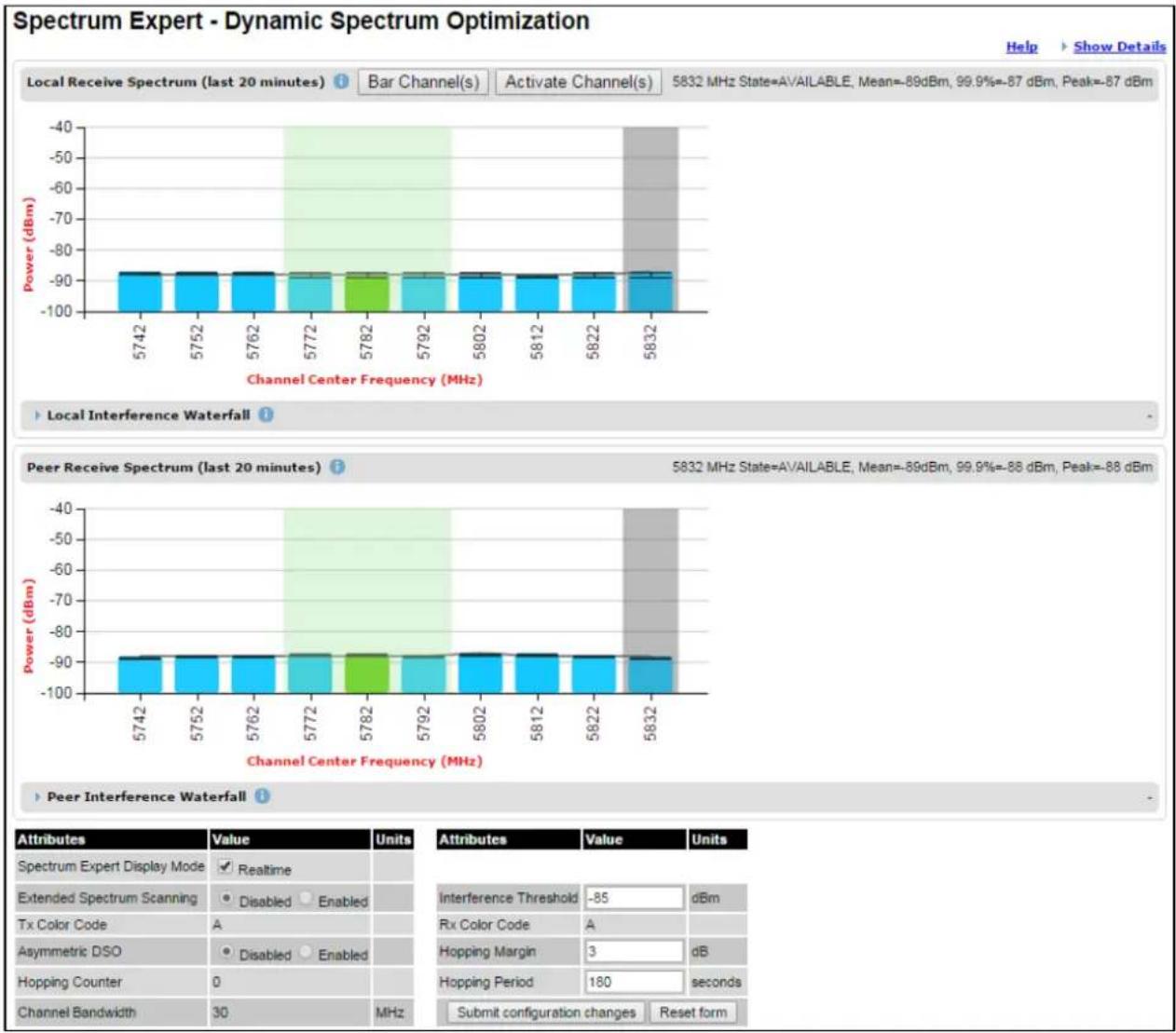
bar
Spectrum Expert - Dynamic Spectrum Optimization | Channel Center Frequency (MHz) | Power (dBm) | | :--- | :--- | | 5742 | -90 | | 5752 | -90 | | 5762 | -90 | | 5772 | -90 | | 5782 | -90 | | 5792 | -90 | | 5802 | -90 | | 5812 | -90 | | 5822 | -90 | | 5832 | -90 | Peer Interference Waterfall | Channel Center Frequency (MHz) | Power (dBm) | | :--- | :--- | | 5742 | -90 | | 5752 | -90 | | 5762 | -90 | | 5772 | -90 | | 5782 | -90 | | 5792 | -90 | | 5802 | -90 | |\( ^{4} \) | -90 | |\( ^{4} \) | -90 | |\( ^{4} \) | -90 | |\( ^{4} \) | -90 | |\( ^{4} \) | -90 | |\( ^{4} \) | -90 | |\( ^{4} \) | -90 | |\( ^{4} \) | -90 | |\( ^{\text{Peer Interference Waterfall}} \) | -90 | | | Attributes | Value | Units | | Spectrum Expert Display Mode ✓ Realtime | | | | Extended Spectrum Scanning ● Disabled ○ Enabled | | | | Tx Color Code A | | | | Asymmetric DSO ● Disabled ○ Enabled | | | | Hopping Counter 0 | | | | Channel Bandwidth 30 MHz | | | Interference Threshold: -85 dBm Rx Color Code A Hopping Margin: 3 dB Hopping Period: 180 seconds Submit configuration changes Reset form
Note When Wireless Network Topology is set to HCMP, only the Local Receive Spectrum is shown on both the Master and the Slaves.
Extended Display Mode
Figure 246 Spectrum Expert page - Extended Display mode

bar
| Channel Center Frequency (MHz) | Power (dBm) | |---|---| | 4422 | -90 | | 4462 | -90 | | 4502 | -90 | | 4542 | -90 | | 4582 | -90 | | 4622 | -90 | | 4662 | -90 | | 4702 | -90 | | 4742 | -90 | | 4782 | -90 | | 4822 | -90 | | 4862 | -90 | | 4902 | -90 | | 4942 | -90 | | 4982 | -90 | | 5022 | -90 | | 5062 | -90 | | 5102 | -90 | | 5142 | -90 | | 5182 | -90 | | 5222 | -90 | | 5262 | -90 | | 5302 | -90 | | 5342 | -90 | | 5382 | -90 | | 5422 | -90 | | 5462 | -90 | | 5502 | -90 | | 5542 | -90 | | 5582 | -90 | | 5622 | -90 | | 5662 | -90 | | 5702 | -90 | | 5742 | -90 | | 5782 | -90 | | 5822 | -90 | Peer Interference Waterfall (Last 20 minutes) | Channel Center Frequency (MHz) | Power (dBm) | | :--- | :--- | | 4422 | -90 | | 4462 | -90 | | 4502 | -90 | | 4542 | -90 | | 4582 | -90 | | 4622 | -90 | | 4662 | -90 | | 4702 | -90 | | 4742 | -90 | | | 4782 | -90 | | | 4822 | -90 | | | 4862 | -90 | | | 4902 | -90 | | | 4942 | -90 | | | 4982 | -90 | | | 5022 | -90 | | | 5062 | -90 | | | 5102 | -90 | | | 5142 | -90 | | | 5182 | -90 | | | 5222 | -90 | | | 5262 | -90 | | | 5302 | -90 | | | 5342 | -90 | | | 5382 | -90 | | | 5422 | -90 | | | 5462 | -90 | | | 5502 | -90 | | | 5542 | -90 | | | 5582 | -90 | | | 5622 | -90 | | | 5662 | -90 | | | 5702 | -90 | | | 5742 | -90 | | | 5782 | -90 | | | 5822 | -90 | Peer Interference Waterfall (Last 20 minutes) | Channel Center Frequency (MHz) | Power (dBm) | |---|---| | 4422 | -90 | | 4462 | -90 | | 4502 | -90 | | 4542 | -90 | | 4582 | -90 | | 4622 | -90 | | 4662 | -90 | | 47O2 | -90 | | 4742 | -90 | | 4782 | -90 | | | 4822 | -90 | | | 4862 | -90 | | | 49O2 | -90 | | | 4942 | -90 | | | 4982 | -90 | | | 5022 | -90 | | | 5062 | -90 | | | 51O2 | -90 | | | 5142 | -90 | | | 5182 | -90 | | | 5222 | -90 | | | 5262 | -90 | | | 53O2 | -90 | | | 5342 | -90 | | | 5382 | -90 | | | 5422 | -90 | | | 5462 | -90 | | | 55O2 | -90 | | | 5542 | -90 | | | 5582 | -90 | | | 5622 | -90 | | | 5662 | -90 | | | 57O2 | -90 | | | 5742 | -90 | | | 5782 | -90 | | '58B' (Peak: +88 dBm, Mean: +88 dBm, Peak: +87 dBm) Interference Threshold: -85 dBm Rx Color Code: A Hopping Margin: 3 dB Hopping Period: 180 seconds Submit configuration changes Reset form


Note Figure 245 shows the default layout for a unit configured as a Master. On a unit configured as Slave, some of the controls at the bottom of the page are not available. In the remainder of this section, the screen shots shown are for the Master Unit.
Note For Spectrum Expert Extended Display mode, Extended Spectrum Scanning is Enabled and Display mode is set to Extended.
Note When Wireless Network Topology is set to HCMP, only the Local Receive Spectrum is shown on both the Master and the Slaves.
Standard Display with extended layout
The page layout may be changed from the compact layout to the extended layout by clicking on the Show Details hyperlink on the top right of the page shown in Figure 245.
This hyperlink is only visible when the Extended Display checkbox in Spectrum Expert Display Mode is not selected.
A screen shot of the Spectrum Expert page in the extended layout is shown in Figure 247. It displays the following additional plots:
• The Local Timeseries, and
• The Peer Timeseries.
These plots are on the right of the corresponding Receive Spectrum plots. See Selecting a Channel and a Time period on page 7-49 for details on the timeseries plots.
Clicking on the Hide Details hyperlink returns to the compact layout.
Figure 247 Spectrum Expert page with Receive Spectrum and Timeseries for the Local unit

bar
| Time (hh:mm) | Power (dBm) | | ------------ | ----------- | | 25:00 | -70 | | 22:00 | -90 | | 19:00 | -90 | | 16:00 | -90 | | 13:00 | -90 | | 10:00 | -90 | | 7:00 | -90 | | 4:00 | -90 | | 1:00 | -90 | | 0:50 | -90 | | 0:30 | -90 | | 0:10 | -90 | | now | -90 |Full layout
The page layout may be extended further to give access to more information on either or both the local and the peer interference spectra.
For the local interference spectrum, clicking on the Local Interference Waterfall hyperlink below the Local Receive Spectrum plot shows:
• The Local Interference Waterfall plot, if the Local TimeSeries was not shown (Figure 248), or
• The Local Interference Waterfall and the Histogram plots otherwise (Figure 249).
The same can be done for the peer section of the page.
Details on how to interpret the Interference Waterfall and Histogram plots are provided in sections. Interpreting the Interference Waterfall plot on page 7-51 and Interpreting the histogram plot on page 7-53 respectively.
Figure 248 Spectrum Expert page showing the Receive Spectrum and Interference Waterfall for the Local unit
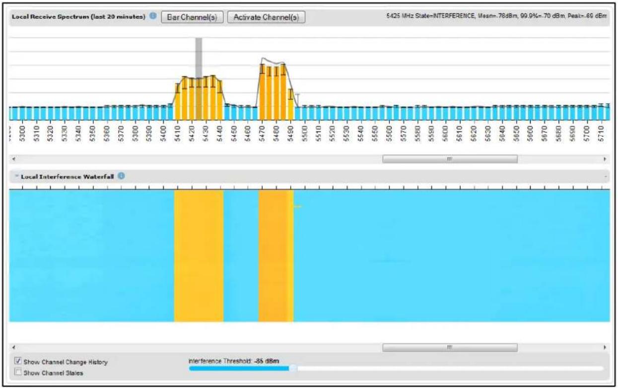
bar_line
| Time (s) | Bar Channel(s) | Interference Waterfall | |----------|----------------|------------------------| | 5300 | Low | No | | 5310 | Low | No | | 5320 | Low | No | | 5330 | Low | No | | 5340 | Low | No | | 5350 | Low | No | | 5360 | Low | No | | 5370 | Low | No | | 5380 | Low | No | | 5390 | Low | No | | 5400 | Low | No | | 5410 | Medium | No | | 5420 | High | Medium | | 5430 | High | High | | 5440 | Medium | Medium | | 5450 | Low | Low | | 5460 | Low | Low | | 5470 | High | High | | 5480 | High | High | | 5490 | Medium | Medium | | 5500 | Low | Low | | 5510 | Low | Low | | 5520 | Low | Low | | 5530 | Low | Low | | 5540 | Low | Low | | 5550 | Low | Low | | 5560 | Low | Low | | 5570 | Low | Low | | 5580 | Low | Low | | 5590 | Low | Low | | 5600 | Low | Low | | 5610 | Low | Low | | 5620 | Low | Low | | 5630 | Low | Low | | 5640 | Low | Low | | 5650 | Low | Low | | 5660 | Low | Low | | 5670 | Low | Low | | 5680 | Low | Low | | 5690 | Low | Low | | 5700 | Low | Low | | 5710 | Low | Low | Local Receive Spectrum (last 20 minutes) / Local Interference Waterfall (Local Interference States) - Show Channel Change History / Show Channel States - Interference Threshold: -85 dBmFigure 249 Spectrum Expert page showing the Receive Spectrum, Timeseries, Interference Waterfall and Histogram for the Local unit

bar
| Time (hh:mm) | Power (dBm) | | ------------ | ----------- | | 25.00 | -90 | | 22.00 | -90 | | 19.00 | -90 | | 16.00 | -90 | | 13.00 | -90 | | 10.00 | -90 | | 7.00 | -90 | | 4.00 | -90 | | 1.00 | -90 | | 0.50 | -90 | | 0.40 | -90 | | 0.30 | -90 | | 0.20 | -90 | | 0.10 | -90 | | 0.01 | -90 | | 0.01% | -90 | | 0.1% | -86 | | 1% | -86 | | 1% | -86 | | 1% | -86 | | 1% | -86 | | 1% | -86 | | 1% | -86 | | 1% | -86 | | 1% | -86 | | 1% | -86 | | 1% (interference threshold) | -86 dBm | | % of Power Level | -100 to -100 dBmSpectrum Expert page with Slave Scan
The page layout in an HCMP Slave with Slave Scan is shown in Figure 250.
When Slave Scan is configured at a Slave ODU, the Spectrum Expert page allows channels to be administratively barred using the Bar Channel(s) and Activate Channel(s) buttons. Bar unused channels to reduce the scan time.
The Slave Scan channel scan can be monitored by observing progress of the green colored channel marker.
Restart the channel scan on the lowest channel using the Force Scan button. This option is useful if physical installation (for example, antenna alignment) is changed whilst a scan is in progress.
Figure 250 Spectrum Expert page with Slave Scan

bar
| Channel | Value (dBm) | | ------- | ----------- | | 4420 | -90 | | 4430 | -90 | | 4440 | -90 | | 4450 | -90 | | 4460 | -90 | | 4470 | -90 | | 4480 | -90 | | 4490 | -90 | | 4500 | -90 | | 4510 | -90 | | 4520 | -90 | | 4530 | -90 | | 4540 | -90 | | 4550 | -90 | | 4560 | -90 | | 4570 | -90 | | 4580 | -90 | | 4590 | -90 | | 4600 | -90 | | 4610 | -90 | | 4620 | -90 | | 4630 | -90 | | 4640 | -90 | | 4650 | -90 |Spectrum Management page
Menu option: System > Spectrum Management
Note that this page is only shown when the Spectrum Expert page has been disabled, as explained in Spectrum Expert and Spectrum Management pages on page 7-32.
Use this page to view and configure spectrum usage. The width of the vertical green bar represents the channel width (10 MHz illustrated).

Note The extended view is available only in Spectrum Expert, and not in Spectrum Management.

Note When Wireless Network Topology is set to HCMP, only the Local Receive Spectrum is shown on both the Master and the Slaves.
Figure 251 Spectrum Management page (Master unit)
Spectrum Management - Dynamic Spectrum Optimization

bar
Local Receive Channel Spectrum | Channel Center Frequency (MHz) | Power (dBm) | | :--- | :--- | | 5732 | -40 | | 5737 | -95 | | 5742 | -96 | | 5747 | -97 | | 5752 | -97 | | 5757 | -96 | | 5762 | -96 | | 5767 | -96 | | 5772 | -95 | | 5777 | -95 | | 5782 | -95 | | 5787 | -95 | | 5792 | -95 | | 5797 | -95 | | 5802 | -95 | | 5807 | -95 | | 5812 | -94 | | 5817 | -93 | | 5822 | -93 | | 5827 | -93 | | 5832 | -93 | | 5837 | -93 | | 5842 | -93 |
line
| Channel Center Frequency (MHz) | Power (dBm) | | ------------------------------ | ----------- | | 5732 | -100 | | 5737 | -100 | | 5742 | -100 | | 5747 | -100 | | 5752 | -100 | | 5757 | -100 | | 5762 | -100 | | 5767 | -100 | | 5772 | -100 | | 5777 | -100 | | 5782 | -100 | | 5787 | -100 | | 5792 | -100 | | 5797 | -100 | | 5802 | -100 | | 5807 | -100 | | 5812 | -100 | | 5817 | -100 | | 5822 | -100 | | 5827 | -100 | | 5832 | -100 | | 5837 | -100 | | 5842 | -100 |
Figure 251 shows the Spectrum Management page layout for a unit configured as a Master. On a unit configured as Slave, some of the controls at the bottom of the page are not available.
Spectrum Management Settings
All spectrum management configuration changes are applied at the master ODU only. These changes are then sent from the master to the slave, so that both master and slave keep identical copies of spectrum management configuration. It is therefore possible to swap master and slave roles on an active PTP 700 link without modifying Spectrum Management configuration.
The default channelization can be modified by varying the lower center frequency attribute in the installation wizard, as described in Wireless Configuration page on page 6-28.

Note Before attempting to improve the performance of the spectrum management algorithm by changing the default configuration, consult the Cambium Point-to-Point distributor or one of the system field support engineers.
Procedure:
• Review the configuration attributes (Table 232)
- Update the attributes as required. At the slave unit, only Page Refresh Period can be updated.
- To save changes, click Submit configuration changes.
Table 232 Spectrum Management attributes
| Attribute | Meaning |
| Spectrum Expert Display Mode | Realtime: When set to Realtime, an additional line appears on theReceive Spectrum plots showing the most recent measurements ofinterference level for every channelExtended: Extended Display mode is visible only when Extended Scanning is enabled.This control is available in the Spectrum Expert page only. |
| Extended Spectrum Scanning | Enabled: Enables scanning of entire DSO full band channels.Disabled: Only the operational subband channels are scanned.This control is available in the Spectrum Expert page only. |
| Spectrum Management Page Refresh Period | The page refreshes automatically according to the setting entered here(in seconds).This control is available in the Spectrum Management page only. |
| Hopping Margin | Uses this margin when making a channel hop decision. If theinterference level of the target channel is lower than that of the activechannel by at least the Hopping Margin, the link will hop to the targetchannel. The default setting is 3 dB in non-radar regions, or 10 dB inradar regions. |
| Asymmetric DSO | Only displayed in non-radar regions when DSO is enabled. The defaultconfiguration of symmetric operation constrains the link to operatesymmetrically, using the same transmit and receive channels. When insymmetric mode the slave unit will always follow the master. If themaster moves to a new channel the slave will hop to the same channel.When the Point-to-Point link is configured as an asymmetric link boththe master and slave are free to select the best channel from their ownset of local interference metrics. |
| Spectrum Management Control | Only displayed in radar regions. The options are DFS and DFS withDSO. |
| Hopping Period | The Spectrum Management algorithm evaluates the metrics every “Hopping Period” seconds (180 seconds by default) looking for a channel with lower levels of interference. If a better channel is located, Spectrum Management performs an automated channel hop. If SNMP or SMTP alerts are enabled an SNMP TRAP or an email alert is sent warning the system administrator of the channel change. |
| Hopping Counter (not configurable) | This is used to record the number of channel hops. The number in the (+) brackets indicates the number of channel changes since the last screen refresh. |
| Interference Threshold | Spectrum Management uses the interference threshold to perform instantaneous channel hops. If the measured interference on a channel exceeds the specified threshold, then DSO will instruct the wireless to immediately move to a better channel. If a better channel cannot be found the PTP 700 Series will continue to use the current active channel. (Default -85 dBm). |
| Interference Tolerance Margin | Only displayed for the PTP 45700 Beam Steer ODU: If the SINR after completing Null Steering is above the Interference Threshold plus the Interference Tolerance Margin and maximum modulation is achieved, the link continues to operate at the same frequency, and a DSO channel change is not considered. |
| Channel Bandwidth (not configurable) | This shows the value of the variable channel bandwidth selected. |
| Tx Color Code (not configurable) | This shows the Tx Color Code selected during Installation. |
| Rx Color Code (not configurable) | This shows the Rx Color Code selected during Installation. |
Interpreting the receive spectrum plot
The Spectrum Expert page has two graphical plots:
- Local Receive Spectrum
• Peer Receive Spectrum
A more detailed example of one of these plots is shown in Figure 245.
For more information, select the Help hyperlink at the top right of the Spectrum Expert page and follow the instructions.
X axis and Y axis
The X-axis shows a stylized view of the selectable wireless channels. Note that the distance between adjacent channels may be smaller than the channel bandwidth. If this is the case, adjacent channels overlap. Channels are displayed separately for clarity. The axis is labeled using the channel center frequencies in MHz. The Y-axis shows the interference power levels from -100 to -40 dBm.
Channel states
The active channel (Channel 9 in Figure 245) is always marked using hatched green and white lines on the Spectrum Management page or solid green on the Spectrum Expert page. The width of the hatching is directly proportional the channel bandwidth or spectral occupancy of the channel.
The individual channel metrics are displayed using a colored bar and an "l" bar. The colored bar represents the channel state (Table 233).
Table 233 Channel states represented in the Spectrum Expert plot
| Color | State | Meaning |
| Green | Active | The channel is currently in use, hosting the wireless link. |
| Orange | Interference | The channel has interference above the interference threshold. |
| Blue | Available | The channel has an interference level below the interference threshold and is considered by the Spectrum Management algorithm suitable for hosting the Point-to-Point link. |
| Light Grey | Barred | The system administrator has barred this channel from use. For improved visibility, an additional red “lock” symbol is used to indicate that a channel is barred but The lock is not shown in Extended view. |
| Red | Radar Detected | A radar signal has been detected and operation on this channel is currently not allowed. |
| Dark Grey | Region Barred | Extended scanned channels outside the range of configured operational subband channels |
Key metrics
The “I” bar and top of the colored bar represent three key metrics (Table 234). The vertical part of the “I” bar represents the statistical spread between the peak and the mean of the statistical distribution.
The arithmetic mean is the true power mean and not the mean of the values expressed in dBm.
Spectrum Management uses the 99.9% Percentile as the prime interference measurement. All subsequent references to interference level refer to this percentile measurement.
Table 234 Key metrics represented in the Spectrum Expert plot
| Metric | Description | How represented |
| Peak of Means | The largest mean interference measurement encountered during the quantization period. The peak of means is useful for detecting slightly longer duration spikes in the interference environment. | Upper horizontal bar. |
| Mean of Means | The arithmetic mean of the measured means during a quantization period. The mean of means is a coarse measure of signal interference and gives an indication of the average interference level measured during the quantization period. The metric is not very good at predicting intermittent interference and is included to show the spread between the Mean of Means, the 99.9% Percentile and the Peak of Means. | Lower horizontal bar. |
| 99.9% Percentile of the Means | The value of mean interference measurement which 99.9% of all mean measurements fall below, during the quantization period. The 99.9% percentile metric is useful for detecting short duration repetitive interference that by its very nature has a minimal effect of the mean of means. | Top of the colored bar. |
| Realtime interference level | The arithmetic mean of the power measured during the last quantization period. The quantization period is two seconds. | Countinuous line. |
Spectrum Expert page in fixed frequency mode
When the link is operating in fixed frequency mode, the Spectrum Expert page uses two visual cues (Figure 252). The main page title has the "Fixed Frequency Mode" suffix and the selected channels are identified by a red capital "F".
Figure 252 Spectrum Expert page for Fixed Frequency - Standard display mode

bar
Spectrum Expert - Fixed Frequency Mode | Channel Center Frequency (MHz) | Power (dBm) | | :--- | :--- | | 4115 | -90 | | 4125 | -90 | | 4135 | -90 | | 4145 | -90 | | 4155 | -90 | | 4165 | -90 | | 4175 | -90 | | 4185 | -90 | | 4195 | -90 | | 4205 | -90 | | 4215 | -90 | | 4225 | -90 | | 4235 | -90 | | 4245 | -90 | | 4255 | -90 | | 4265 | -90 | | 4275 | -90 | | 4285 | -90 | | 4295 | -90 | | 4305 | -90 | | 4315 | -90 | | 4325 | -90 | | 4335 | -90 | | 4345 | -90 | | 4355 | -90 | | 4365 | -90 | | 4375 | -90 | | 4385 | -90 | | 4395 | -90 | | 4405 | -90 | | 4415 | -90 | | 4425 | -90 | | 4435 | -90 | | 4445 | -90 | | 4455 | -90 | | 4465 | -90 | | 4475 | -90 | | 4485 | -90 | | 4495 | -90 | | 4505 | -90 | | 4515 | -90 | | 4525 | -90 | | 4535 | -90 | | 4545 | -90 | | 4555 | -90 | | 4565 | -90 | | 4575 | -90 | | 4585 | -90 | | 4595 | -90 | | 4605 | -90 | | 4615 | -90 | | 4625 | -90 | | 4635 | -90 | | 4645 | -90 | | 4655 | -90 | | 4665 | -90 | | 4675 | -90 | | 4685 | -90 | | 4695 | -90 | | 4705 | -90 | | 4715 | -90 | | 4725 | -90 | | 4735 | -90 | | 4745 | -90 | | 4755 | -90 | | 4765 | -90 | | 4775 | -90 | | 4785 | -90 | | 4795 | -90 | | 4805 | -90 | | 4815 | -90 | | 4825 | -90 | | 4835 | -90 | | 4845 | -90 | | 4855 | -90 | | 4865 | -90 | | 4875 | -90 | | 4885 | -90 | | 4895 | -90 | | 4905 | -90 | | 4915 | -90 | | 4925 | -90 | | 4935 | -90 | | 4945 | -90 | | 4955 | -90 | | 4965 | -90 | | 4975 | -90 | | 4985 | -90 | Peer Receiver Spectrum (last 20 minutes) Power (dBm) Peer Interference Waterfall | | | | | | | | | | | | | | | | | | | | | | | | | | | | | | | | | | | | | | | | | | | | | | | | | | | | | | | | | | | | | | | | | | | | | | | | | | | | | | | | | | | | | | | | | | | | | | | | | | | | | Peer Interference Waterfall (-7,7,7,7,7,7,7,7,7,7,7,7,7,7,7,7,7,7,7,7,7,7,7,7,7,7,7,7,7,7,7,7,7,7,7,7,7,7,7,7,7,7,7,7,7,7,7,7,7,7,7Figure 253 Spectrum Expert page for Fixed Frequency - Extended display mode

bar
| Channel Center Frequency (MHz) | Power (dBm) | | ------------------------------ | ----------- | | 4415 | -90 | | 4455 | -90 | | 4495 | -90 | | 4535 | -90 | | 4575 | -90 | | 4615 | -90 | | 4655 | -90 | | 4695 | -90 | | 4735 | -90 | | 4775 | -90 | | 4815 | -90 | | 4855 | -90 | | 4895 | -90 | | 4935 | -90 | | 4975 | -90 | | 5015 | -90 | | 5055 | -90 | | 5095 | -90 | | 5135 | -90 | | 5175 | -90 | | 5215 | -90 | | 5265 | -90 | | 5295 | -90 | | 5335 | -90 | | 5375 | -90 | | 5415 | -90 | | 5455 | -90 | | 5495 | -90 | | 5535 | -90 | | 5575 | -90 | | 5615 | -90 | | 5665 | -90 | | 5695 | -90 | | 5735 | -90 | | 5775 | -90 | | 5815 | -90 | | 5855 | -90 |Channel barring is disabled in fixed frequency mode; it is not required as dynamic channel hopping is prohibited in this mode.
The only controls available to the master are the Spectrum Expert Display Mode and Interference Threshold attributes. They will have no effect on the operation of the wireless link and will only effect the generation of the channel spectrum graphics.
Spectrum Expert page in radar avoidance mode
When the link is operating in radar avoidance mode, the Spectrum Expert page (Figure 254) contains the following additional information:
- The main page title has the "Radar Avoidance" suffix.
- The only controls available to the master are the Interference Threshold attribute. This has no effect on the operation of the wireless link and will only affect the generation of the channel spectrum graphics.
• Extra color coding of the interference histogram is provided (Table 235).
Figure 254 Spectrum Expert page with radar avoidance - Standard Display Spectrum Expert - Radar Avoidance with Dynamic Spectrum Optimization

bar
| Channel Center Frequency (MHz) | Power (dBm) | |---|---| | 5487 | -90 | | 5497 | -90 | | 5507 | -85 | | 5517 | -90 | | 5527 | -90 | | 5537 | -90 | | 5547 | -90 | | 5557 | -85 | | 5567 | -85 | | 5577 | -50 | | 5587 | -85 | | 5597 | -85 | | 5607 | -90 | | 5617 | -90 | | 5627 | -90 | | 5637 | -90 | | 5647 | -90 | | 5657 | -70 | | 5667 | -60 | | 5677 | -50 | | 5687 | -90 | | 5697 | -90 | | 5707 | -90 | The chart displays two panels: the top panel shows 'Local Receive Spectrum (last 20 minutes)' with a mean of -90 dBm and a peak of -88 dBm; the bottom panel shows 'Peer Receive Spectrum (last 20 minutes)' with a mean of -89 dBm and a peak of -88 dBm. Error bars are shown for each data point. The labels above the charts indicate the channel center frequencies in MHz.| Attributes | Value | Units |
| Spectrum Expert Display Mode | Realtime | |
| Extended Spectrum Scanning | Disabled Enabled | |
| Tx Cobr Code | A | |
| Spectrum Management Control | DFS DFS with DSO | |
| Hopping Counter | 0 | |
| Channel Bandwidth | 30 | MHz |
| Attributes | Value | Units |
| Interference Threshold | -85 | dBm |
| Rx Color Code | A | |
| Hopping Margin | 10 | dB |
| Hopping Period | 180 | seconds |
| Submit configuration changes Reset form | ||
Figure 255 Spectrum Expert page with radar avoidance - Extended Display Spectrum Expert - Radar Avoidance with Dynamic Spectrum Optimization

bar
| Channel Center Frequency (MHz) | Local Interference Waterfall (dBm) | Peer Receive Spectrum (dBm) | |---|---|---| | 4415 | -90 | -90 | | 4455 | -90 | -90 | | 4495 | -90 | -90 | | 4535 | -90 | -90 | | 4575 | -90 | -90 | | 4615 | -90 | -90 | | 4655 | -90 | -90 | | 4695 | -90 | -90 | | 4735 | -90 | -90 | | 4775 | -90 | -90 | | 4815 | -90 | -90 | | 4855 | -90 | -90 | | 4895 | -90 | -90 | | 4935 | -90 | -90 | | 4975 | -90 | -90 | | 5015 | -90 | -90 | | 5055 | -90 | -90 | | 5095 | -90 | -90 | | 5135 | -90 | -90 | | 5175 | -90 | -90 | | 5215 | -90 | -90 | | 5255 | -90 | -90 | | 5295 | -90 | -90 | | 5335 | -90 | -90 | | 5375 | -90 | -90 | | 5415 | -90 | -90 | | 5455 | -90 | -90 | | 5495 | -88 | -88 | | 5535 | -88 | -88 | | 5575 | -88 | -88 | | 5615 | -88 | -88 | | 5655 | -88 | -88 | | 5695 | -88 | -88 | | 5735 | -88 | -88 | | 5775 | -88 | -88 | | 5815 | -88 | -88 | | 5855 | -88 | -88 | | Channel Center Frequency (MHz) | Local Interference Waterfall (dBm) | |---|---| | 4415 | -90 | | 4455 | -90 | | 4495 | -90 | | 4535 | -90 | | 4575 | -90 | | 4615 | -90 | | 4655 | -90 | | 4695 | -90 | | 4735 | -90 | | 4775 | -90 | | 4815 | -90 | | 4855 | -90 | | 4895 | -90 | | 4935 | -90 | | 4975 | -90 | | 5015 | -90 | | 5055 | -90 | | 5095 | -90 | | 5135 | -90 | | 5175 | -90 | | 5215 | -90 | | 5255 | -90 | | 5295 | -90 | | 5335 | -90 | | 5375 | -90 | | 5415 | -90 | | 5455 | -90 | | 5495 | -88 | | 5535 | -88 | | 5575 | -88 | | 5615 | -88 | | 5655 | -88 | | 5695 | -88 | | 5735 | -88 | | 5775 | -88 | | 5815 | -88 | | 5855 | -88 | Peer Interference Waterfall (dBm) Attributes Value Units Spectrum Expert Display Mode Valid Extended Spectrum Scanning Disabled Enabled Tx Color Code A Attributes Value Units Channel Bandwidth 30 MHz Rx Color Code A Submit configuration changes Reset formWhen operating with RTTT (Road transport and Traffic Telematics) Avoidance enabled or other regulatory restrictions on channel usage, all channels marked with a "no entry" symbol with their associated statistics colored black are the prohibited channels. These channels are never used to host the wireless link, but CAC measurements are still taken so that adjacent channel biases can be calculated correctly and so the user can see if other equipment is in use.
Table 235 Channel states in the Spectrum Expert plot (radar avoidance)
| Color | State and color | Meaning |
| Green | Active | This channel is currently in use hosting the Point-to-Point wireless link. |
| Orange | Interference | This channel has interference above the interference threshold |
| Blue | Available | This channel has an interference level below the interference threshold and is considered by the Spectrum Management algorithm suitable for hosting the Point-to-Point link |
| Dark grey | Barred | The system administrator has barred this channel from use. Because the low signal levels encountered when a unit is powered up in a laboratory environment prior to installation (which makes the grey of the channel bar difficult to see). An additional red “lock” symbol is used to indicate that a channel is barred. |
| Light grey | Unavailable | This channel needs to be monitored for one minute and found free of radar signal before it can be used for transmitting. |
| Red | Radar Detected | Impulsive Radar Interference has been detected on this channel and the channel is unavailable for 30 minutes. At the end of the 30 minute period a Channel Availability Check is required to demonstrate no radar signals remain on this channel before it can be used for the radio link. |
| Black | Region Bar | This channel has been barred from use by the local region regulator |
Barring channels
Procedure:
- Log into the Master unit.
- Select menu option System > Spectrum Expert. The Spectrum Expert page is displayed.
- Select one channel by clicking on the graphical display. If required, select additional channels using control clicking, or select a range of channels using shift clicking. The example in Figure 256 shows three channels selected at 4965 MHz, 4970 MHz and 4975 MHz.
- Click on the Bar Channel(s) button. A confirmation dialogue is displayed as shown in Figure 257. Click OK.
- Barred channels are indicated by the lock symbol as shown in Figure 258 on page 7-49.
To activate previously barred channels, select the barred channels and click on Activate Channel(s).

Note The Bar Channel(s) and Activate Channel(s) buttons are available on the Master unit, but not on the Slave unit.
Figure 256 Selecting channels for barring

bar
Spectrum Expert - Dynamic Spectrum Optimization | Channel Center Frequency (MHz) | Local Receive Spectrum (last 20 minutes) Power (dBm) | Peer Receive Spectrum (last 20 minutes) Power (dBm) | | :--- | :--- | :--- | | 4945 | -93 | -93 | | 4950 | -91 | -91 | | 4955 | -91 | -91 | | 4960 | -91 | -91 | | 4965 | -91 | -91 | | 4970 | -91 | -91 | | 4975 | -91 | -92 | | 4980 | -91 | -91 | | 4985 | -91 | -91 |Figure 257 Channel barring confirmation
![Spectrum Expert Are you sure you want to bar the selected operational channel(s): [5-7]? The bar will take effect immediately. Ok Cancel](/content/2026/05/942230/images/f578d9f24a0ec020400868179d8159e617f962df90e98214e4ebbfb8cd57fc3a.jpg)
Figure 258 Barred channels

bar
Spectrum Expert - Dynamic Spectrum Optimization | Channel Center Frequency (MHz) | Power (dBm) | | :--- | :--- | | 4945 | -92 | | 4950 | -91 | | 4955 | -91 | | 4960 | -91 | | 4965 | -90 | | 4970 | -90 | | 4975 | -90 | | 4980 | -90 | | 4985 | -90 | Local Receive Spectrum (last 20 minutes) Bar Channel(s) Activate Channel(s) 4985 MHz State=AVAILABLE, Mean=-94dBm, 99.9%=-92 dBm, Peak=-92 dBm Peer Receive Spectrum (last 20 minutes) 4985 MHz State=AVAILABLE, Mean=-93dBm, 99.9%=-91 dBm, Peak=-91 dBm Peer Interference WaterfallSelecting a Channel and a Time period
The Timeseries plot uses measurements for the selected channel. The Histogram plot uses measurements for the selected channel and the selected measurement period.
To select a channel, place the cursor in the Receive Spectrum display or the Interference Waterfall display. The Timeseries plot updates automatically to show the data for the selected channel. To select a combination of channel and time period, place the cursor in the Interference Waterfall display. The Histogram plot automatically updates to show data for the selected channel and time period.
The selected channel is shown with a grey background in the Receive Spectrum display and by the horizontal position of square brackets in the Interference Waterfall display. The selected time period is shown by the vertical position of the square brackets.
The Selected Channel is centred on 5740 MHz, and the time period is from 2:20 to 9:00 in the example in Figure 259.
The selected frequency and time period are also displayed in the heading for the Timeseries and Histogram plots.
Figure 259 Selecting a channel on the Receive Spectrum

bar
| Time (MHz) | Power (dBm) | |------------|-------------| | 25.00 | -90 | | 22.00 | -85 | | 19.00 | -85 | | 16.00 | -85 | | 13.00 | -85 | | 10.00 | -85 | | 7.00 | -85 | | 4.00 | -85 | | 1.00 | -60 | | 0.50 | -60 | | 0.40 | -60 | | 0.30 | -60 | | 0.20 | -60 | | 0.10 | -60 | | now | -60 |To freeze the selection of channel and time period, click on the cursor position. The frequency and time period are now fixed until a new combination is selected by clicking in a different location. The frozen time period is shown by red brackets in the Interference Waterfall display.
Interpreting the timeseries plot
This plot displays the interference measurements of all previous measurement quantization periods for the selected channel, up to a maximum of 25 h (Figure 260).
The channel is selected as described in Selecting a Channel and a Time period. The center frequency of the selected channel is indicated in MHz at the top right of the Timeseries plot.
The colored lines represent interference measurements, with the color map provided in Table 236.
A white background indicates the measurement period which is used to generate the Receive Spectrum plot. Typically, only the last 20 min are used, although any period of time where the wireless link has been down is excluded.
Figure 260 Spectrum Expert, Timeseries plot

line
| Time (hh:mm) | Power (dBm) | | ------------ | ----------- | | 25:00 | -50 | | 22:00 | -50 | | 19:00 | -50 | | 16:00 | -50 | | 13:00 | -50 | | 10:00 | -50 | | 7:00 | -50 | | 4:00 | -50 | | 1:00 | -50 | | 0:50 | -50 | | 0:40 | -50 | | 0:30 | -50 | | 0:20 | -70 | | 0:10 | -50 | | now | -50 |Table 236 Interference represented in the time series plot
| Color | Meaning |
| RED | Peak of Means interference measurement |
| BLACK | 99.9% percentile of means interference measurement |
| BLUE | Mean of Means interference measurement |
Interpreting the Interference Waterfall plot
The Interference Waterfall indicates the level of interference for all the channels in the band over the last 25 h. Figure 261 shows a screen capture example.
The channel and measurement period are selected as described in Selecting a Channel and a Time period on page 7-49 The center frequency of the selected channel and the time period are indicated at the top right of the Interference Waterfall plot.
The X-axis corresponds to the channel center frequency and is horizontally aligned with the Receive Spectrum plot.
The Y-axis corresponds to the time in the past in hours and minutes, with the most recent period being at the top of the plot.
Each channel and measurement period is indicated using the color scale given in Table 233.
Figure 261 Spectrum Expert, Interference Waterfall plot

line
| Time (hh:mm) | Value | | ------------ | ----- | | 0:01 | 0 | | 0:10 | 0 | | 0:20 | 0 | | 0:30 | 0 | | 0:40 | 0 | | 0:50 | 0 | | 1:00 | 0 | | 1:30 | 0 | | 1:60 | 0 | | 19:00 | 0 | | 22:00 | 0 | | 25:00 | 0 |Setting the interference threshold
The interference threshold may be set using the sliding control located directly below the Interference Waterfall plot. This is an alternative to the method described in Spectrum Management Settings on page 7-38. For either method, the change to the Interference Threshold is not taken into account until the Submit button is clicked.
Viewing the active channel history
To display the active channel history, tick the Show Channel Change History control right below the Interference Waterfall plot. The active channel history over the last 25 hours is plotted as a black line overlay on the Interference Waterfall plot. A circle is displayed every time the active channel has changed. By hovering above the circle, the reason for the channel change is indicted, as shown in Figure 262.
Figure 262 Spectrum Expert, Interference Waterfall with active channel history

line
| Time (hh:mm) | Value | | ------------ | ----- | | 0 | 0.10 | | 4 | 4.00 |Viewing the channel states
To display the Channel States, tick the Show Channel State control right below the Interference Waterfall plot. Figure 263 shows an example of the Interference Waterfall when the Channel States are displayed. The colors used are defined in Channel states on page 7-42.
Figure 263 Spectrum Expert page, Interference Waterfall plot with channel states

line
| Time (hh:mm) | Value | | ------------ | ----- | | 0 | 0.10 | | 4 | 4.00 | | 8 | 4.00 |Interpreting the histogram plot
The histogram plot indicates the percentage of the measurements in the selected measurement period where the interference level for the selected channel is at a given level (Figure 264).
The channel and measurement period are selected as described in Selecting a Channel and a Time period on page 7-49. The combined selection is indicated graphically by a pair of brackets in the Waterfall plot, and in text form on the top right of the Histogram plot, as shown in Figure 263.
The X-axis corresponds to a percentage of the measurements in the measurement period on a logarithmic scale.
The Y-axis corresponds to actual interference level in dBm.
The bar for each each power level is of the same color as in the Interference Waterfall plot.
Figure 264 Spectrum Expert page, histogram plot

bar
| % Time at Power Level | Power (dBm) | | :--- | :--- | | 0.01% | -58 | | 0.1% | -52 | | 0.5% | -49 | | 1% | -86 | | 10% | -86 | | 100% | -86 |Spectrum Expert example
In this example from a real-world link, shown in Figure 265, the channel at 5740 MHz has been selected for analysis.
The Spectrum display is based in the most recent 20 minute period. The height of the colored bar in the selected channel shows that the 99.9th percentile of the interference is at about -66 dBm. The orange color of the bar is a reminder that this level is above the interference threshold of -85 dBm.
The upper bar of the "I" bar indicates the peak level of the interference. The lower bar of the "I" bar indicates the mean level of the interference. The height of the "I" bar represents the peak to mean ratio. In this channel, the peak to mean ratio is about 15 dB.
The red and black traces in the Timeseries plot show that the peak and mean interference levels have been maintained at approximately constant levels over a period of about two hours. Before that period, the interference level was considerably lower, at about -90 dBm.
In the Interference Waterfall plot, the selected time period is from 2 hours 20 minutes to 9 hours ago. The plot shows that interference occurred suddenly, across a broad band of channels, shortly after the selected period, or about two hours ago, and that it has been maintained at an approximately constant level since then. The Histogram plot shows that, prior to the onset of interference, the interference level was consistently close to -90 dBm, corresponding to the earlier part of the Timeseries plot.
Figure 265 Spectrum Expert, example 1
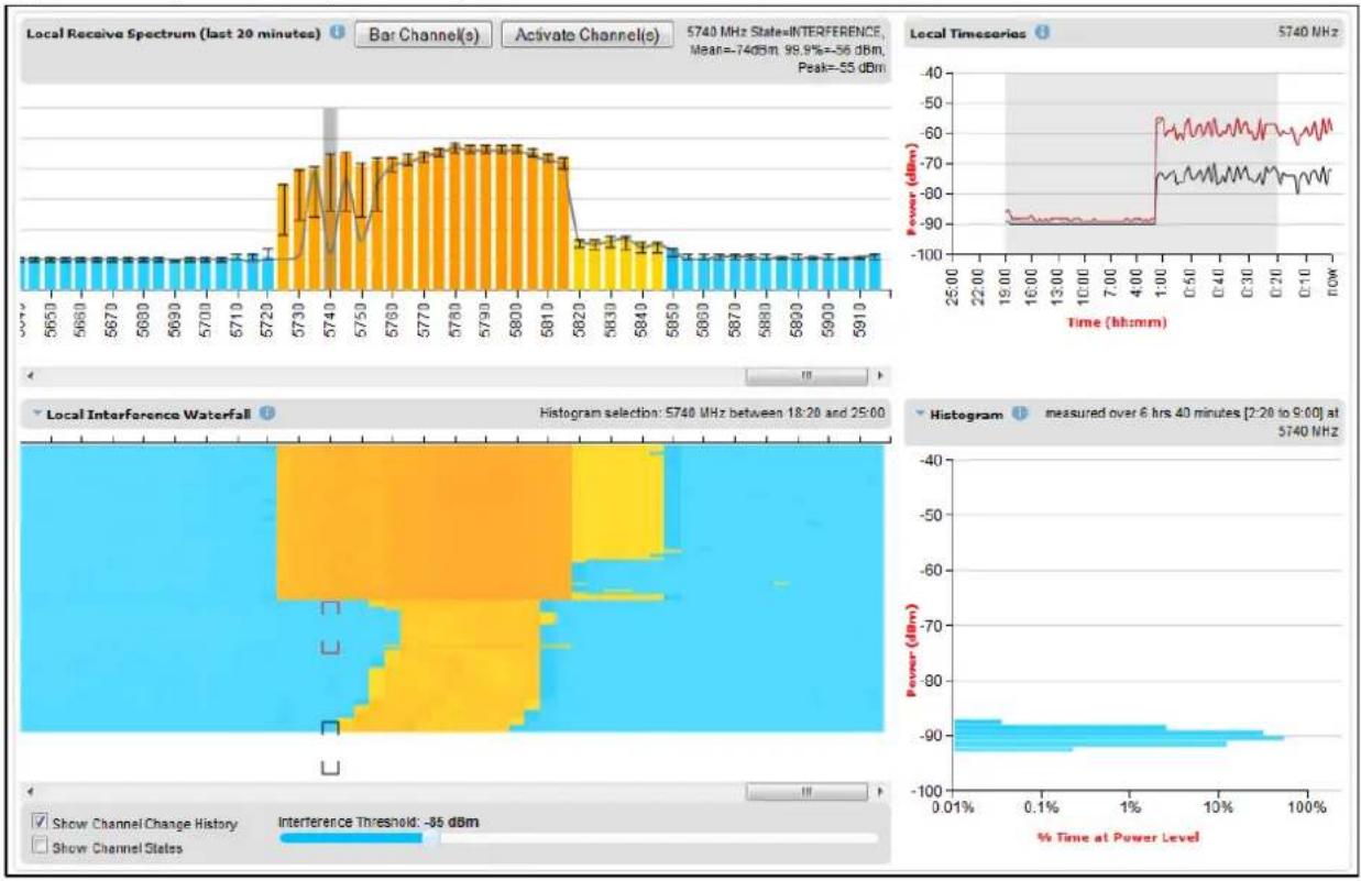
bar
| Time (hh:mm) | Power (dBm) | | ------------ | ----------- | | 25:00 | -90 | | 22:00 | -90 | | 19:00 | -90 | | 16:00 | -90 | | 13:00 | -90 | | 10:00 | -90 | | 7:00 | -90 | | 4:00 | -90 | | 1:00 | -60 | | 0:50 | -60 | | 0:40 | -60 | | 0:30 | -60 | | 0:20 | -60 | | 0:10 | -60 | | NOW | -60 |In Figure 266, the time period for the Histogram plot has been set to the most recent 20 minutes. The histogram shows that interference levels are distributed over the range of approximately -74 dBm to approximately -54 dBm.
Figure 266 Spectrum Expert, example 2

bar
| Time (hh:mm) | Power (dBm) | | ------------ | ----------- | | 25.00 | -90 | | 22.00 | -90 | | 19.00 | -90 | | 16.00 | -90 | | 13.00 | -90 | | 10.00 | -90 | | 7.00 | -90 | | 4.00 | -90 | | 1.00 | -60 | | 0.50 | -60 | | 0.40 | -60 | | 0.30 | -60 | | 0.20 | -60 | | 0.10 | -60 | | 0.01 | -60 | | 0.1% | -65 | | 1% | -70 | | 10% | -75 | | 100% | -85 |The interference observed in Figure 266 for the channel at 5740 MHz during the recent two hour period is not compatible with satisfactory operation a PTP 700 link.
The situation is, if anything, even worse in the channel at 5780 MHz, as shown in Figure 267, where the interference level was historically worse, and in the recent period was consistently in the range -52 dBm to -58 dBm.
Figure 268 shows the recent history of the channel at 5835 MHz. In this case, the peak interference is less than -80 dBm. This channel is likely to support satisfactory operation at a receive signal level of -60 dBm or greater.
Figure 267 Spectrum Expert, example 3
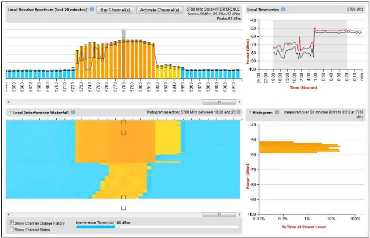
bar
| Time (hh:mm) | Power (dBm) | | ------------ | ----------- | | 25:00 | -40 | | 22:00 | -60 | | 19:00 | -70 | | 16:00 | -80 | | 13:00 | -75 | | 10:00 | -85 | | 7:00 | -90 | | 4:00 | -60 | | 1:00 | -50 | | 0.50 | -55 | | 0.40 | -58 | | 0.30 | -60 | | 0.20 | -62 | | 0.10 | -65 | | 0.01 | -68 | | 0.01% | -70 | | 0.1% | -75 | | 1% | -80 | | 1% | -85 | | 10% | -90 | | 10% | -95 | | 100% | -100 |Figure 268 Spectrum Expert, example 4

bar_line
| Time (kHz) | Power (dBm) | |------------|-------------| | 25:00 | -90 | | 22:00 | -90 | | 19:00 | -90 | | 16:00 | -90 | | 13:00 | -90 | | 10:00 | -90 | | 7:00 | -90 | | 4:00 | -90 | | 1:00 | -90 | | 0.50 | -90 | | 0.40 | -90 | | 0.30 | -90 | | 0.20 | -90 | | 0.10 | -90 | | now | -90 |Managing security
This section describes the following procedures:
- Exiting FIPS 140-3 approved mode
• Zeroising sensitive security parameters
Other security configuration procedures are described in Security menu on page 6-122.
Exiting FIPS 140-3 approved mode
To exit from the FIPS 140-3 approved mode, install standard (non-FIPS) PTP 700 firmware.

Note The sensitive security parameters (SSPs) are zeroized when the unit exits from the FIPS 140-3 approved mode.
Zeroizing sensitive security parameters
Use this procedure to zeroize sensitive security parameters (SSPs) as follows:
• Key of keys.
- AES encryption keys for the wireless interface.
- Private key for the HTTPS/TLS interface.
- Entropy value for the HTTPS/TLS interface.
- Private key for the User-supplied Device Certificate.
- User account passwords for the web-based interface.
• SNTP server keys for SHA1
• SNMPv3 USM authentication keys
• SNMPv3 USM privacy keys
Procedure:
- On the Security menu, click Zeroize SSPs.
- Click Select Zeroize SSPs and Reboot Wireless Unit.
- Confirm the reboot.

Note Alternatively, select the Zeroize SSPs option in Recovery mode as described in eroize Sensitive Security Parameters on page 7-87.

Attention When SSPs have been zeroized, all user accounts are disabled, and the ODU is returned to the "first use" condition. See Creating a user account on page 6-6 to create a new user account for the web-based interface.
System statistics
This section describes how to use the system statistics pages to manage the performance of the PTP 700 link, use the following web pages:
System Statistics page
Menu option: System > Statistics. Use this page to check system statistics.
System histograms
The System Histograms section of the System Statistics page (Figure 269 and Figure 270) contains eight diagnostic attributes that are presented as arrays of four elements (Table 237).
Figure 269 System Histograms section of the System Statistics page (PTP Topology)
| System Statistics | |||||
| Attributes | Value | Units | |||
| System Histograms | |||||
| Transmit Power | 25.0, | 17.5, | -15.0, | 14.0 | dBm |
| Receive Power | -37.2, | -64.0, | -110.0, | -51.3 | dBm |
| Vector Error | 7.2, | -19.6, | -31.0, | -29.4 | dB |
| Link Loss | 110.8, | 79.6, | 0.0, | 107.3 | dB |
| Signal Strength Ratio | 0.7, | 0.0, | -1.0, | 0.0 | dB |
| Transmit Data Rate | 20.40, | 14.73, | 0.00, | 20.40 | Mbps |
| Receive Data Rate | 20.40, | 9.14, | 0.00, | 20.40 | Mbps |
| Aggregate Data Rate | 40.80, | 23.88, | 0.00, | 40.80 | Mbps |
| Histogram Measurement Period | 00:07:46 | ||||
| Reset System Histogram Measurement Period | |||||
Figure 270 System Histograms section of the System Statistics page (HCMP Topology, Wireless Interface Selector set to "All Wireless Interfaces")
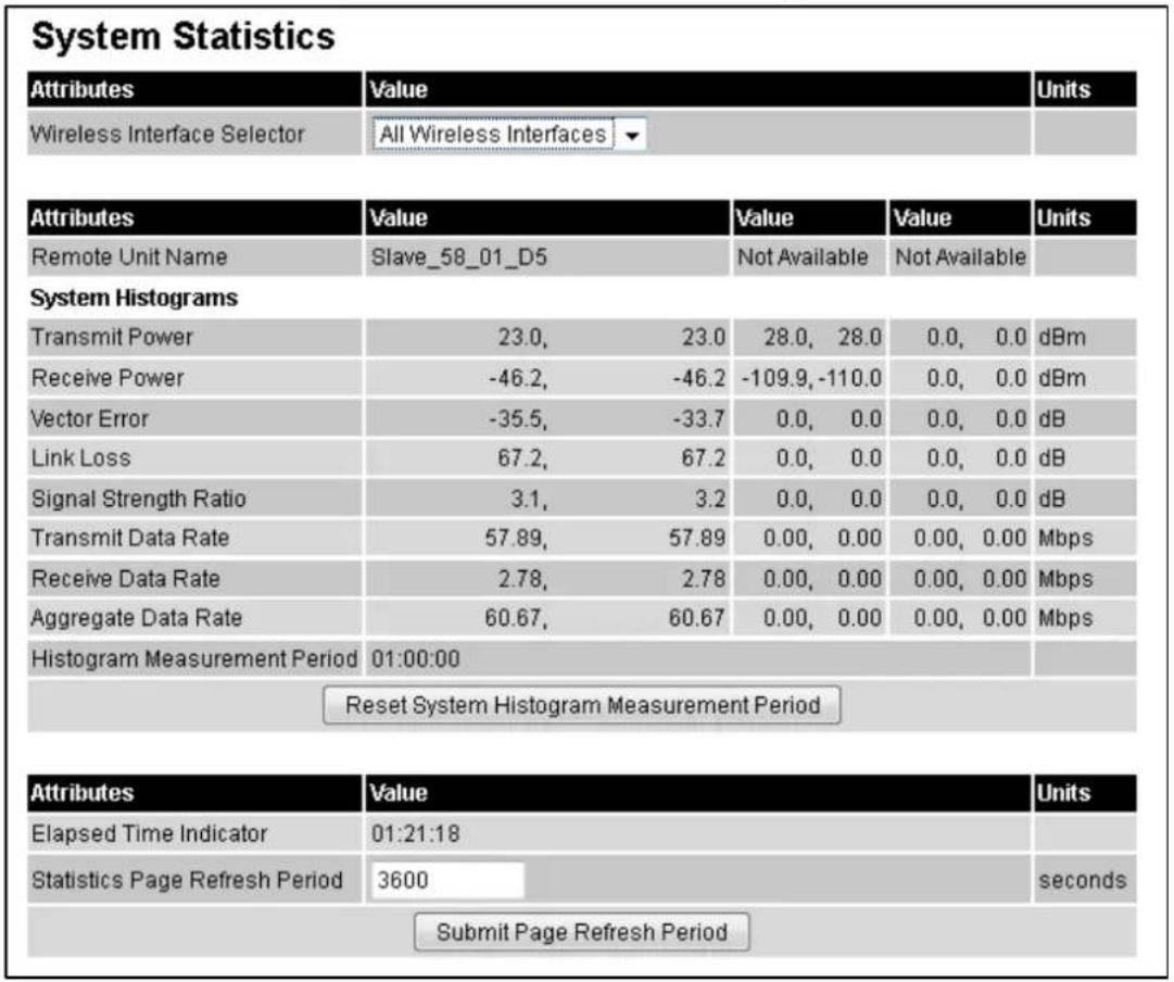
The element arrays represent the following:
• Max: The maximum value measured over the last hour.
• Mean: The mean of a set of values recorded at one second intervals over the last hour.
- Min: The minimum value measured over the last hour.
- Latest: The latest value measured.
The values are calculated over the time that has elapsed since the link was established or since the measurement period was reset.
Use the Diagnostics Plotter page on page 7-76 to plot these attributes against time. Use the Generate Downloadable Diagnostics page on page 7-78 to extract historical data for these attributes to a CSV file.
Procedure:
• To reset and restart measurement, click Reset System Histograms and Measurement Period.
Table 237 System Histogram attributes in the System Statistics page
| Attribute | Meaning |
| Transmit Power | The transmit power histogram, calculated over a one hour period. |
| Receive Power | The receive power histogram, calculated over a one hour period. |
| Vector Error | The vector error measurement compares (over a one hour period) the received signal IQ modulation characteristics to an ideal signal to determine the composite vector error magnitude. |
| Link Loss | Link loss calculated (over a one hour period) as follows:Peer_Tx_Power (dBm) - Local_Rx_Power (dBm) + 2 x Antenna_Pattern (dBi) |
| Signal Strength Ratio | The Signal Strength Ratio (calculated over a one hour period) is:Power received by the vertical antenna Configure (dB) ÷Power received by the horizontal antenna Configure (dB)This ratio is presented as: max, mean, min, and latest. The max, min and latest are true instantaneous measurements; the mean is the mean of a set of one second means.Signal Strength Ratio is an aid to debugging a link. If it has a large positive or negative value then investigate the following potential problems:An antenna coaxial lead may be disconnected.When spatial diversity is employed, the antenna with the lower value may be pointing in the wrong direction.When a dual polar antenna is deployed, the antenna may be directed using a side lobe rather than the main lobe.When there is a reflection from water on the link and spatial diversity is employed, then one expects large, slow swings in Signal Strength Ratio. This indicates the antenna system is doing exactly as intended. |
| Transmit, Receive and Aggregate Data Rates | The data rates in the transmit direction, the receive direction and in both directions, expressed in Mbps (max, mean, min, and latest). The max, min and latest are true instantaneous measurements. The mean is the mean of a set of one second means. |
| Histogram Measurement Period | The time over which the system histograms were collected. |
Wireless Port Counters (PTP topology)
The System Counters section of the System Statistics page (Figure 271) contains Data Port Counters (Table 238), Management Agent Counters (Table 239) and Wireless Port Counters and Performance Information (Table 240).
Figure 271 System Counters section of the System Statistics page
| Attributes | Value | Units |
| Data Port Counters | ||
| Tx Frames | 197 (+197) | |
| Rx Frames | 248 (+248) | |
| Second Data Port Counters | ||
| Tx Frames | 14 (+14) | |
| Rx Frames | 3 (+3) | |
| Management Agent Counters | ||
| Packets To Internal Stack | 203 (+206) | |
| Packets From Internal Stack | 293 (+293) | |
| Wireless Port Counters and Performance Information | ||
| Tx Frames | 100 (+100) | |
| Rx Frames | 104 (+104) | |
| Link Symmetry | 1 to 1 | |
| Link Capacity | 226.65 | Mbps |
| Transmit Modulation Mode | 258QAM 0.81 (Single) (30 MHz) | |
| Receive Modulation Mode | 258QAM 0.81 (Dual) (30 MHz) | |
| Receive Modulation Mode Detail | Running At User-Configured Max Modulation Mode | |
| Wireless Link Availability | 100.0000 | % |
| Data Bridging Availability | 100.0000 | % |
| Byte Error Ratio | 1.355e-8 | |
| Counter Measurement Period | 00:01:32 | |
| Reset System Counters | ||
Procedure:
• To reset all system counters to zero, click Reset System Counters.
The packet counter attributes each contain a number in parentheses; this shows the number of packets received since the last page refresh.
Table 238 Data Port Counters
| Attribute | Meaning |
| Tx Frames | The total number of good frames the bridge has sent for transmission through the port selected for Data Service |
| Rx Frames | The total number of good frames the bridge has received through the port selected for Data Service |
Table 239 Management Agent Counters
| Attribute | Meaning |
| Packets To Internal Stack | The total number of good packets the bridge has transmitted to the internal stack (for example, ARP, PING and HTTP requests). |
| Packets From Internal Stack | The total number of good packets the bridge has received from the internal stack (ARP responses, PING replies, HTTP responses). |
Table 240 Wireless Port Counters and Performance Information
| Attribute | Meaning |
| Tx Frames | Total number of good frames on the Data path, the bridge has sent for transmission through the wireless interface. |
| Rx Frames | Total number of good frames on the Data path, the bridge has received from the wireless interface. |
| Tx Frame Management | Total number of good management frames, the bridge has sent for transmission through the wireless interface |
| Link Symmetry | Ratio between transmit and receive time in the TDD frame. The first number is the time allowed for the transmit direction and the second number is the time allowed for the receive direction. |
| Link Capacity | The maximum aggregate data capacity available for user traffic under the current radio link conditions, assuming the units have been connected using Gigabit Ethernet. The sum of the displayed Transmit and Receive data rates may be lower than this figure if the link is not fully loaded by the current traffic profile. |
| Transmit Modulation Mode | The modulation mode currently being used on the transmit channel. The number in brackets after the modulation mode and coding rate string is the effective data rate available to all MAC layer protocols. |
| Receive Modulation Mode | The modulation mode currently being used on the receive channel. The number in brackets after the modulation mode and coding rate string is the effective data rate available to all MAC layer protocols. |
| Receive Modulation Mode Detail | The receive modulation mode in use. For a list of values and their meanings, see Table 220. |
| Wireless Link Availability | Wireless link availability calculated since the last system counters reset. |
| Ethernet Bridging Availability | Link availability for bridging Ethernet traffic calculated since the last reset of the system counters. This is the percentage of time in which the Ethernet Bridging Status attribute has been set to “Enabled”. |
| Byte Error Ratio | The ratio of detected Byte errors to the total number of bytes since the last system reboot. This measurement is made continually using null frames when there is no user data to transport. |
| Counter Measurement Period | The time over which the system counters were collected. |
Other attributes
The bottom section of the System Statistics page (Figure 272) contains two attributes (Table 241).
Figure 272 Other attributes section of the System Statistics page

Procedure:
• After updating the Statistics Page Refresh Period field, click Submit Page Refresh Period.
Table 241 Other attributes in the System Statistics page
| Attribute | Meaning |
| Elapsed Time Indicator | Elapsed time since the last system reboot. |
| Statistics Page Refresh Period | The statistics page refreshes automatically according to the setting entered here (in seconds). |
Wireless Port Counters page
PTP topology
Menu option: System > Statistics > Wireless Port Counters (Figure 273).
Use this page to check the Ethernet performance of the wireless bridge.
Figure 273 Wireless Port Counters page (PTP topology)
| Attributes | Value | Units |
| Tx Frames | 132 (+32) | |
| Tx Frames Q0 | 0 (+0) | |
| Tx Frames Q1 | 125 (+125) | |
| Tx Frames Q2 | 0 (+0) | |
| Tx Frames Q3 | 0 (+0) | |
| Tx Frames Q4 | 0 (+0) | |
| Tx Frames Q5 | 0 (+0) | |
| Tx Frames Q6 | 0 (+0) | |
| Tx Frames Q7 | 7 (+7) | |
| Tx Drops Q0 | 0 (+0) | |
| Tx Drops Q1 | 0 (+0) | |
| Tx Drops Q2 | 0 (+0) | |
| Tx Drops Q3 | 0 (+0) | |
| Tx Drops Q4 | 0 (+0) | |
| Tx Drops Q5 | 0 (+0) | |
| Tx Drops Q6 | 0 (+0) | |
| Tx Drops Q7 | 0 (+0) | |
| Tx Frames Second Data | 3 (+3) | |
| Tx Drops Second Data | 0 (+0) |
Procedure:
• Review the attributes (Table 242).
- To change the refresh period, update the Counter Page Refresh Period attribute and click Submit Page Refresh Period.
• To reset all counters to zero, click Reset System Counters.
Table 242 Wireless Port Counters attributes
| Attribute | Meaning |
| Tx/Rx Frames | Number of frames transmitted and received over the wireless bridge. |
| Rx Frames With Crc Error | Number of received frames with CRC errors. |
| Tx/Rx Frames Q0...Q7 | Number of transmitted and received frames for each Traffic Class. |
| Tx Drops Q0...Q7 | Number of transmitted frames dropped for each Traffic Class. |
| Rx Drops Q0...Q7 | Total number of frames dropped due to the lack of sufficient capacity in the receive buffer, for each Traffic Class. |
HCMP topology
Menu option: System > Statistics > Wireless Port Counters (Figure 274 to Figure 276).
Use this page to check the Ethernet performance of the wireless bridge.
Figure 274 Wireless Port Counters page (Master, HCMP topology, Wireless Interface Selector set to a single link)

Figure 275 Wireless Port Counters page (Master, HCMP topology, Wireless Interface Selector set to All Wireless Links)
| Wireless Port Counters | ||||
| Attributes | Value | Units | ||
| Wireless Interface Selector | All Wireless Interfaces ▼ | |||
| Attributes | Value | Value | Value | Units |
| Remote Unit Name | Slave_58_01_D5 | Not Available | Not Available | |
| Tx Frames | 75,333 (+0) | 0 (+0) | 0 (+0) | |
| Rx Frames | 171,324 (+0) | 0 (+0) | 0 (+0) | |
| Rx Frames With Error | 3 (+0) | 0 (+0) | 0 (+0) | |
| Tx Frames Q0 | 75,333 (+0) | 0 (+0) | 0 (+0) | |
| Tx Frames Q1 | 0 (+0) | 0 (+0) | 0 (+0) | |
| Tx Frames Q2 | 0 (+0) | 0 (+0) | 0 (+0) | |
| Tx Frames Q3 | 0 (+0) | 0 (+0) | 0 (+0) | |
| Tx Drops Q0 | 0 (+0) | 0 (+0) | 0 (+0) | |
| Tx Drops Q1 | 0 (+0) | 0 (+0) | 0 (+0) | |
| Tx Drops Q2 | 0 (+0) | 0 (+0) | 0 (+0) | |
| Tx Drops Q3 | 0 (+0) | 0 (+0) | 0 (+0) | |
| Rx Frames Q0 | 171,322 (+0) | 0 (+0) | 0 (+0) | |
| Rx Frames Q1 | 0 (+0) | 0 (+0) | 0 (+0) | |
| Rx Frames Q2 | 0 (+0) | 0 (+0) | 0 (+0) | |
| Rx Frames Q3 | 2 (+0) | 0 (+0) | 0 (+0) | |
| Byte Error Ratio | 3.533e-9 | 0 | 0 | |
| Attributes | Value | Units | ||
| Counter Page Refresh Period | 3600 | seconds | ||
| Counter Measurement Period | 01:25:58 | |||
| Submit Page Refresh Period Reset System Counters | ||||
Figure 276 Wireless Port Counters page (Slave, HCMP topology)

Procedure:
- Only on a device configured as in HCMP topology as a Master, select one interface using the Wireless Interface Selector. Note the Remote MAC Address indicates the MAC address of the unit currently connected, if any, to the selected wireless interface.
• Review the attributes (Table 243). - To change the refresh period, update the Counter Page Refresh Period attribute and click Submit Page Refresh Period.
• To reset all counters to zero, click Reset System Counters.
Table 243 Wireless Port Counters attributes, HCMP mode
| Attribute | Meaning |
| Tx/Rx Frames | Number of frames transmitted and received over the wireless link. |
| Rx Frames With Error | Number of received frames with errors. |
| Tx/Rx Frames Q0...Q3 | Number of transmitted and received frames for each Traffic Class. |
| Tx Drops Q0...Q3 | Number of frames discarded for each Traffic Class by taildrop. |
Main Port Counters page (PTP topology only)
Menu option: System > Statistics > Main Port Counters (Figure 277). Use this page to check the Ethernet performance of the PSU port. The displayed counters vary depending on which port is being used to bridge the traffic.
Figure 277 Main Port Counters page (when main port is bridging traffic)
Main Port Counters
| Attributes | Value | Units |
| Tx Octets | 684,506 (+684,506) | |
| Tx Frames | 6,177 (+2) | |
| Tx Drops | 0 (+0) | |
| Tx Broadcasts | 5,368 (+5,368) | |
| Tx IEEE1588 Event Frames | 0 (+0) | |
| Tx Frames 64 Bytes | 5,912 (+5,912) | |
| Tx Frames 65 To 127 Bytes | 41 (+41) | |
| Tx Frames 128 To 255 Bytes | 17 (+17) | |
| Tx Frames 256 To 511 Bytes | 6 (+6) | |
| Tx Frames 512 To 1023 Bytes | 4 (+4) | |
| Tx Frames 1024 To 1600 Bytes | 197 (+197) | |
| Tx Frames 1601 To Max Bytes | 0 (+0) | |
| Attributes | Value | Units |
| Rx Octets | 398,584 (+398,584) | |
| Rx Frames | 6,044 (+2) | |
| Rx Frames With Crc Error | 0 (+0) | |
| Rx Broadcasts | 5,554 (+5,554) | |
| Rx IEEE1588 Event Frames | 0 (+0) | |
| Rx Frames Undersize | 0 (+0) | |
| Rx Frames 64 Bytes | 5,968 (+5,968) | |
| Rx Frames 65 To 127 Bytes | 57 (+57) | |
| Rx Frames 128 To 255 Bytes | 2 (+2) | |
| Rx Frames 256 To 511 Bytes | 11 (+11) | |
| Rx Frames 512 To 1023 Bytes | 2 (+2) | |
| Rx Frames 1024 To 1600 Bytes | 4 (+4) | |
| Rx Frames 1601 To Max Bytes | 0 (+0) | |
| Rx Frames Oversize | 0 (+0) | |
| Rx Pause Frames | 0 (+0) |
| Attributes | Value | Units | |
| Counter Page Refresh Period | 3600 | seconds | |
| Submit Page Refresh Period | |||
| Attributes | Value | Units | |
| Counter Measurement Period | 00:08:09 | ||
| Reset System Counters | |||
Procedure:
• Review the attributes (Table 244).
- To change the refresh period, update the Counter Page Refresh Period attribute and click Submit Page Refresh Period.
• To reset all counters to zero, click Reset System Counters.
Table 244 Main Port Counters attributes
| Attribute | Meaning |
| Tx/Rx Octets | Total number of octets (bytes) transmitted and received over the interface. |
| Tx/Rx Frames | Total number of frames transmitted and received over the interface. This includes both good and bad frames. |
| Tx Drops | Total number of transmit frames dropped. |
| Rx Frames With Crc Error | Total number of received frames with CRC errors. |
| Tx/Rx Broadcasts | Total number of good transmitted and received broadcast packets. |
| Tx/Rx IEEE1588 Event Frames | Only displayed when IEEE 1588 Transparent Clock is enabled.Total number of transmitted or received IEEE 1588 Event frames |
| Rx Frames Undersize | Total number of frames received that are less than 64 bytes. |
| Tx/Rx Frames 64 Bytes | Total number 64 byte frames transmitted and received. |
| Tx/Rx Frames xxxx to yyyy Bytes | Total number of frames transmitted and received in the size range xxxx to yyyy bytes. |
| Tx/Rx Frames 1601 to Max bytes | Total number of frames transmitted and received in the size range 1601 to maximum bytes. |
| Rx Frames Oversize | Total number of frames received that are greater than the maximum number of bytes. |
| Rx Pause Frames | Total number of received pause frames. |
Aux Port Counters page (PTP topology only)
Menu option: System > Statistics > Aux Port Counters (Figure 278).
Use this page to check the Ethernet performance of the Aux port.
Figure 278 Aux Port Counters page (when Aux port is allocated to the Local Management Service)
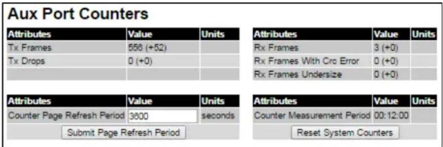
Procedure:
• Review the attributes (Table 245).
- To change the refresh period, update the Counter Page Refresh Period attribute and click Submit Page Refresh Period.
• To reset all counters to zero, click Reset System Counters.
Table 245 Aux Port Counters attributes
| Attribute | Meaning |
| Tx/Rx Frames | Total number of frames transmitted and received over the interface. This includes both good and bad frames. |
| Rx Frames With Crc Error | Total number of received frames with CRC errors. |
| Tx Drops | Number of frames dropped due to excessive collision, late collision or frame ageing |
| Rx Frames Undersize | Number of short frames (<64 Bytes) with or without a valid CRC |
SFP Port Counters page (PTP topology only)
Menu option: System > Statistics > SFP Port Counters (Figure 279).
Use this page to check the Ethernet performance of the SFP port.
Figure 279 SFP Port Counters page (when SFP port is allocated to the Local Management Service)

Procedure:
- Update the attributes (Table 246).
- To change the refresh period, update the Counter Page Refresh Period attribute and click Submit Page Refresh Period.
• To reset all counters to zero, click Reset System Counters.
Table 246 SFP Port Counters attributes
| Attribute | Meaning |
| Tx/Rx Frames | Total number of frames transmitted and received over the interface. This includes both good and bad frames. |
| Rx Frames With Crc Error | Total number of received frames with CRC errors. |
Ethernet Port Counters page (HCMP topology only)
Menu option: System > Statistics > Ethernet Port Counters (Figure 280). Use this page to check the performance of all Ethernet. The displayed counters vary depending on which port is being used to bridge the traffic.
Figure 280 Ethernet Port Counters page (HCMP topology)
Ethernet Port Counters
Main Port Counters
| Attributes | Value | Units |
| Tx Octets | 3,465,824 (+0) | |
| Tx Frames | 2,638 (+0) | |
| Tx Broadcasts | 0 (+0) | |
| Attributes | Value | Units |
| Rx Octets | 113,761 (+0) | |
| Rx Frames | 1,464 (+0) | |
| Rx Frames With Error | 0 (+0) | |
| Rx Broadcasts | 0 (+0) | |
| Rx Frames Undersize | 0 (+0) | |
| Rx Frames Oversize | 0 (+0) |
Aux Port Counters
| Attributes | Value | Units |
| Tx Octets | 0 (+0) | |
| Tx Frames | 0 (+0) | |
| Tx Broadcasts | 0 (+0) | |
| Attributes | Value | Units |
| Rx Octets | 0 (+0) | |
| Rx Frames | 0 (+0) | |
| Rx Frames With Error | 0 (+0) | |
| Rx Broadcasts | 0 (+0) | |
| Rx Frames Undersize | 0 (+0) | |
| Rx Frames Oversize | 0 (+0) |
SFP Port Counters
| Attributes | Value | Units |
| Tx Octets | 0 (+0) | |
| Tx Frames | 0 (+0) | |
| Tx Broadcasts | 0 (+0) | |
| Attributes | Value | Units |
| Rx Octets | 0 (+0) | |
| Rx Frames | 0 (+0) | |
| Rx Frames With Error | 0 (+0) | |
| Rx Broadcasts | 0 (+0) | |
| Rx Frames Undersize | 0 (+0) | |
| Rx Frames Oversize | 0 (+0) |
| Attributes | Value | Units |
| Counter Page Refresh Period | 5 | seconds |
| Submit Page Refresh Period | ||
| Attributes | Value | Units |
| Counter Measurement Period | 01:52:50 | |
| Reset System Counters | ||
Procedure:
- Review the attributes (Table 247).
- To change the refresh period, update the Counter Page Refresh Period attribute and click Submit Page Refresh Period.
• To reset all counters to zero, click Reset System Counters.
Table 247 Ethernet Port Counters attributes (HCMP topology)
| Attribute | Meaning |
| Tx/Rx Octets | Total number of octets (bytes) transmitted and received over the interface. |
| Tx/Rx Frames | Total number of frames transmitted and received over the interface. This includes both good and bad frames. |
| Rx Frames With Error | Total number of received frames with CRC errors. |
| Tx/Rx Broadcasts | Total number of good transmitted and received broadcast packets. |
| Rx Frames Undersize | Total number of frames received that are less than 64 bytes. |
| Rx Frames Oversize | Total number of frames received that are greater than the maximum number of bytes. |
Management Counters page (HCMP topology only)
Menu option: System > Statistics > Management Counters (Figure 281). Use this page to check the performance of all Ethernet. The displayed counters vary depending on which port is being used to bridge the traffic.
Figure 281 Management Counters page (HCMP topology)

Procedure:
- Review the attributes (Table 248).
- To change the refresh period, update the Counter Page Refresh Period attribute and click Submit Page Refresh Period.
• To reset all counters to zero, click Reset System Counters.
Table 248 Management Counters attributes (HCMP topology)
| Attribute | Meaning |
| Tx Frames Management | Total number of frames transmitted over the management interface. |
| Tx Drops Management | Total number of transmit frames dropped over the management interface. |
| Rx Frames Management | Total number of frames received over the management interface. |
SyncE Status page
Menu option: System > Statistics > SyncE Status
Use this page to monitor the state of the Synchronous Ethernet function.
Figure 282 SyncE Status page
| SyncE Status | |||||
| Attributes | Value | Units | Attributes | Value | Units |
| Sync E Tracking State | Locked Local, Holdover Acquired | ||||
| Main PSU Port | |||||
| Main PSU Port Accepted QL Rx | QL-PRC | Main PSU Port Sync E Rx Status | Good | ||
| Main PSU Port QL Rx | QL-PRC | Main PSU Port Sync E Master Slave Status | Slave | ||
| Main PSU Port QL Tx | QL-DNU / QL-DUS | Main PSU Port Gigabit Master Slave Status | Slave | ||
| Aux Port | |||||
| Aux Port QL Rx | None | Aux Port Sync E Master Slave Status | Master | ||
| Aux Port QL Tx | QL-PRC | Aux Port Gigabit Master Slave Status | Not Applicable | ||
| SFP Port | |||||
| SFP Port QL Rx | None | SFP Port Sync E Master Slave Status | Master | ||
| SFP Port QL Tx | None | SFP Port Gigabit Master Slave Status | Slave | ||
| Page Refresh Period | 3 | Seconds | Submit Page Refresh Period | ||
SyncE Status
Procedure:
- Review the attributes
- To change the refresh period, update the Page Refresh Period attribute and click Submit Page Refresh Period
Table 249 Sync E Status attributes
| Attribute | Meaning |
| Sync E Tracking State | The state of the Synchronous Ethernet state machine. See Table 250 for further details. |
| Main PSU Port Accepted QL Rx | The “accepted” QL received by the Main PSU Port. This should be the same as Main PSU Port QL Rx, unless:an “Overwrite” has been configuredthe system is starting up or recovering from an exception |
| Main PSU Port QL Rx | The QL currently being received at the Main PSU Port |
| Main PSU Port QL Tx | The QL currently being transmitted at the Main PSU Port |
| Main PSU Port SyncE Rx Status | The overall status of the incoming synchronous Ethernet signal on the Main PSU port. This port is available as a valid synchronization source if the status is Good. The port may potentially be a valid source in the near future if the status is Wait-to-Restore. |
| Main PSU Port Sync E Master Slave Status | This attribute indicates if the Main PSU Port is operating as a Synchronous Ethernet master (providing a source of timing for downstream devices) or slave (receiving a source of timing from an upstream device). |
| Main PSU Port Gigabit Master Slave Status | This attribute indicates if the Main PSU Port's Gigabit Ethernet physical interface is operating as a master (generating a clock) or slave (locking to a clock generated at the other end of the Ethernet link). |
| Aux Port QL Rx | The QL currently being received on the Aux Port |
| Aux Port Accepted QL Rx | The “accepted” QL received by the Aux Port. This should be the same as Aux Port QL Rx, unless the system is starting up or recovering from an exception |
| Aux Port QL Tx | The QL currently being transmitted at the Aux Port |
| Aux Port Sync E Master Slave Status | The Aux Port operates as a Synchronous Ethernet master (providing a source of timing for downstream devices). |
| Aux Port Gigabit Master Slave Status | This attribute indicates if the Aux Port's Gigabit Ethernet physical interface is operating as a master (generating a clock) or slave (locking to a clock generated at the other end of the Ethernet link). |
| SFP Port QL Rx | The QL currently being received on the SFP Port |
| SFP Port Accepted QL Rx | The “accepted” QL received by the SFP Port. This should be the same as SFP Port QL Rx, unless:an “Overwrite” has been configuredthe system is starting up or recovering from an exceptionThe ODU synchronizes to the best frequency reference as determined by the Port Accepted QL Rx values at the nominated Sync E Slave Ports of local and remote ODUs. |
| SFP Port QL Tx | The QL currently being transmitted at the SFP Port |
| SFP Port Sync E Master Slave Status | This attribute indicates if the SFP Port is operating as a Synchronous Ethernet master (providing a source of timing for downstream devices) or slave (receiving a source of timing from an upstream device). |
| SFP Port Gigabit Master Slave Status | This attribute indicates if the SFP Port's Gigabit Ethernet physical interface is operating as a master (generating a clock) or slave (locking to a clock generated at the other end of the Ethernet link).The Master Slave Status is Not Applicable unless a Copper SFP module is present. |
The "Sync E Tracking State" attribute can take the following values:
Table 250 Sync E Tracking State
| Value | Meaning |
| Disabled | The synchronous Ethernet feature is disabled. |
| Acquiring Wireless Lock | Synchronous Ethernet is not operational because real-time clocks have not completed alignment. |
| Free Running | Synchronous Ethernet is operational, but with no timing source or history. This is a temporary state. |
| Locked Local, Acquiring Holdover | Sync E tracking has locked to a synchronisation signal from a cabled Ethernet port on the local ODU. This is a temporary state until the unit has acquired holdover history. |
| Locked Local, Holdover Acquired | Sync E tracking has locked to a synchronisation signal from a cabled Ethernet port on the local ODU and has acquired holdover history. |
| Holdover | There is currently no source for the tracking loop, but previously the tracking loop was in a Locked, Holdover Acquired state. The system is using the last known good frequency. |
| Locked Remote, Acquiring Holdover | The tracking loop has locked to a synchronisation signal from the remote ODU. This is a temporary state until the unit has acquired holdover history. |
| Locked Remote, Holdover Acquired | The tracking loop has locked to a synchronisation signal form the remote ODU and has acquired holdover history. |
In normal operation, with the Synchronous Ethernet feature enabled and a valid timing source present, one end of the link should be in the “Locked Local, Holdover Acquired State”, the other end should be in the “Locked Remote, Holdover Acquired” state.
The Sync E Tracking State attribute remains in the Acquiring Wireless Lock state for a period of time after the wireless link has established whilst the two ODUs establish precise synchronization. The duration of this period depends on channel bandwidth, varying from less than one minute at 45 MHz, up to two minutes for 5 MHz.
Diagnostics Plotter page
Menu option: System > Diagnostics Plotter (Figure 283 and Figure 284).
Use this page to monitor the performance of an operational PTP 700 link over time.
Figure 283 Diagnostic Plotter page (PTP topology)
Diagnostic Plotter
The plot displays three traces. Maximum values are displayed in red, mean values are displayed in purple and minimum values are displayed in blue.

line
| Metric | Value | | ---------------- | ----- | | Vector Error | 6.9 | | Trace Selection | Max | | Page Refresh Period | 10 | | Seconds | |Figure 284 Diagnostic Plotter page (HCMP topology)
Diagnostic Plotter
The plot displays three traces. Maximum values are displayed in red, mean values are displayed in purple and minimum values are displayed in blue.

Procedure:
- Only on a device configured as in HCMP topology as a Master, set the Wireless Interface Selector to the Wireless Interface the diagnostic data needs to be displayed for. Note the Remote MAC Address indicated the MAC address of the unit currently connected, I any, to the selected wireless interface.
- Select a diagnostic from the Diagnostics Selector drop-down list. These are the same as the System Histogram attributes in the System Statistics page (Table 237) plus those listed in Table 251.
- Tick the required Trace Selection boxes: Max, Mean and Min.
- Update the Page Refresh Period as required. The default period is 3600 seconds (1 hour). To monitor the performance of a link in real time, select a much shorter period, for example 60 seconds.
- Click Plot Selected Diagnostic. The selected diagnostic trace is displayed in the graph. Maximum values are displayed in red, mean values are displayed in purple and minimum values are displayed in blue.
Table 251 Diagnostic Plotter specific System Histogram attributes
| Attribute | Meaning |
| PCB Temperature | The temperature in degrees Celsius measured by a sensor on the printed circuit board of the ODU. The PCB temperature will normally be higher than the ambient temperature. |
| Tx Link Capacity Utilization | The Tx Link Capacity Utilization measures the percentage of the instantaneous transmit capacity actually uses to carry traffic. Note that this percentage is relative to the instantaneous capacity of the link in the transmit direction and that this capacity is dependent over time of the modulation the link operates in. |
Generate Downloadable Diagnostics page
Menu option: System > Diagnostics Plotter > CSV Download (Figure 285).
Use this page to download diagnostics data to a CSV file.
Figure 285 Generate Downloadable Diagnostics page

Procedure:
- Select a diagnostic from the Diagnostics Selector drop-down list.
- Click Generate Diagnostics. The Generate Downloadable Diagnostics page is redisplayed with the name of the generated CSV file.
- Click on the CSV file name and save the CSV file to the hard drive of the local computer.
- Open the CSV file in MS Excel and use it to generate reports and diagrams. The CSV file contains at most 5784 entries, recorded over a 32 day period:
• 3600 entries recorded in the last hour.
• 1440 entries recorded in the previous 24 hours.
• 744 entries recorded in the previous 31 days.
Recovery mode
This section describes how to recover a PTP 700 unit from configuration errors or firmware image corruption.
Entering recovery mode
Use this procedure to enter recovery mode manually.

Note The unit may enter recovery mode automatically, in response to some failures.

Note Once the unit has entered recovery, it will switch back to normal operation if no access has been made to the recovery web page within 30 seconds.

Note See Transition of digital signature algorithms on page 1-78 for details of a transition in digital signatures of replacement firmware.
Procedure:
1 Apply power to PSU for at least 10 seconds.
2 Remove power for two seconds.
3 Re-apply power to the PSU.
4 When the unit is in recovery mode, access the web interface by entering the default IP address 169.254.1.1. The Recovery Image Warning page is displayed:


5 Click on the warning page image. The Recovery Option Page is displayed (Figure 286).
6 Review the Software Version and Recovery Reason (Table 252).
7 Select a recovery option (Table 253).
Figure 286 Recovery Options page
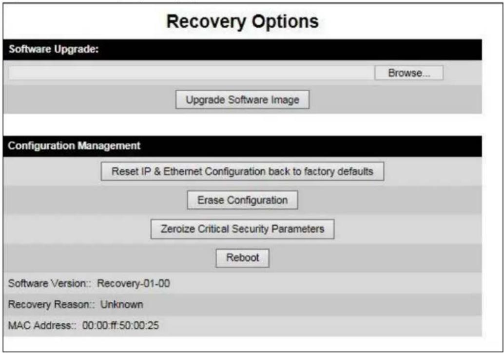
Table 252 Recovery Options attributes
| Attribute | Meaning |
| Software Version | The firmware version of the recovery operating system permanently installed during manufacture. |
| Recovery Reason | The reason the unit is operating in Recovery mode, for example “Invalid or corrupt image”.“Unknown” usually means there has been a power outage. |
| MAC Address | The MAC address of the unit programmed during manufacture. |
Table 253 Recovery Options buttons
| Button | Purpose |
| Upgrade Software Image | Use this option to restore a working firmware version when firmware corruption is suspected, or when an incorrect firmware image has been loaded. Refer to Upgrading firmware image on page 7-83. |
| Reset IP & Ethernet Configuration back to factory defaults | Use this option to reset the IP and Ethernet attributes to factory defaults. Refer to Resetting IP & Ethernet configuration on page 7-84. |
| Erase Configuration | Use this option to reset the entire configuration of the unit to factory defaults. Refer to Resetting all configuration data on page 7-86. |
| Zeroize Sensitive Security Parameters | Use this option to reset the security configuration to default values. Refer to eroize Sensitive Security Parameters on page 7-87. |
| Reboot | Use this option to reboot the unit. Refer to Rebooting the unit on page 7-89. |
Upgrading firmware image
Use this option to restore a working firmware image from the Recovery Options page (Figure 286).
Procedure:
1 Click Browse.
2 Navigate to the required firmware image. This may be the most recent image if firmware corruption is suspected, or an older image if an incorrect image has just been loaded. Click on the image and click Open.
RECOVERY-02-00 loads only firmware images with the DLD3 file extension. Earlier Recovery versions load only firmware images with the DLD2 file extension.
3 Click Upgrade Software Image. The Confirmation page is displayed. Click Program Software Image into Non-Volatile Memory. The Upgrade Progress Tracker page is displayed:

bar
Upgrade Progress Tracker | Metric | Value (%) | |---|---| | Writing software image to FLASH: | 27 | | Overall Upgrade Progress | 77 |4 When the Software Upgrade Complete page is displayed, check that the correct image has been downloaded:
Software Upgrade Complete
The software upgrade was completed Successfully. To complete the upgrade a system reboot is required. Please use the 'Reboot Wireless Unit' button below to reboot the unit.
Current software image description
Software Version: 50650-01-00
Reboot Wireless Unit
5 Click Reboot Wireless Unit. When the "Are you sure?" message is displayed, click OK.
6 The unit will now reboot and restart in normal operational mode, and the link should recover. If the unit or link fails to recover, refer to Testing link end hardware on page 8-7.

Note The unit will not upload FIPS versions of the firmware unless the unit has the AES encryption and FIPS licenses installed.

Note SSPs are automatically zeroized if FIPS firmware is loaded in a unit to replace standard (non-FIPS) firmware, or standard (non-FIPS) firmware is loaded in a unit to replace FIPS firmware.

Attention When SSPs have been zeroized, all user accounts are disabled, and the ODU is returned to the "first use" condition. See Creating a user account on page 6-6 to create a new user account for the web-based interface.
Resetting IP & Ethernet configuration
Use this option in the Recovery Options page to reset IPv4, IPv6 and Ethernet configuration to default values (Figure 286). This procedure resets the IP Version attribute to IPv4. It also resets the IPv6 configuration. The reset action affects the following attributes:
- IP Version
- IPv4 Address
- Subnet Mask
- Gateway IP Address
• use VLAN For Management Interfaces
• VLAN Management VID
• VLAN Management Priority - IPv6 Address
- IPv6 Prefix Length
- IPv6 Gateway Address
- Data Service
• Management Service
- Local Management Service
• Data Port Wireless Down Alert
• Management Port Wireless Down Alert
• Main PSU Port Auto Negotiation
• Main PSU Port Auto Neg Advertisement
• Main PSU Port Auto Mdix
• Aux Port Auto Negotiation
• Aux Port Auto Neg Advertisement
- Aux Port Auto Mdix
• Aux Port Power Over Ethernet Output
• SFP Port Auto Negotiation
• SFP Port Auto Neg Advertisement
- SFP Port Auto Mdix
- Local Packet Filtering
• SNMP Access Control
- Access Control
- IP Address Label
Procedure:
1 Click Reset IP & Ethernet Configuration back to factory defaults. The reset pop up box is displayed:
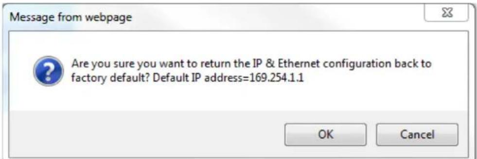
2 Record the IP address, as it will be needed to log into the unit after recovery.
3 Click OK. The reset confirmation page is displayed:
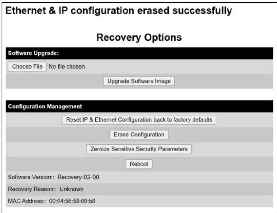
4 Click Reboot. When the "Are you sure you want to REBOOT this unit?" message is displayed, click OK.
5 The unit will now reboot. The unit should now start up in normal mode but with the IP and Ethernet configuration reset to factory defaults. If the unit fails to recover, refer to Testing link end hardware on page 8-7 and Cable Diagnostics on page 8-2.
Resetting all configuration data

Note Wireless Topology is not reset by this procedure.
Use this option in the Recovery Options page to reset the entire configuration of the unit (including IP, Ethernet and SSPs) to default values (Figure 286).
Procedure:
1 Click Erase Configuration. The erase pop up box is displayed:
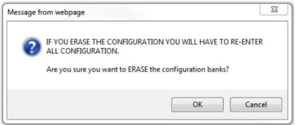
2 Click OK. The erase confirmation page is displayed:
Lower Non-volatile configuration bank erased successfully Upper Non-volatile configuration bank erased successfully SSP Non-volatile configuration bank erased successfully Recovery Options

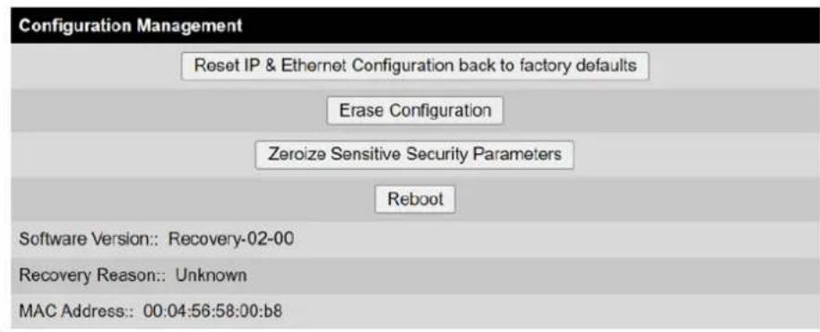
3 Click Reboot. When the confirmation message is displayed, click OK.
4 The unit reboots and starts up in normal mode but with all configuration reset to default values. If the unit fails to start up, refer to Testing link end hardware on page 8-7 and Cable Diagnostics on page 8-2.
eroize Sensitive Security Parameters
Use this option in the Recovery Options page to reset the security configuration of the unit to default values (Figure 286). This action includes the following attributes:
• Key of Keys
- Encryption Algorithm
- Wireless Encryption Key
- HTTPS Private Key
- HTTPS Public Key Certificate
• Random Number Generator Entropy - User-supplied Device Private Key
- HTTP Access Enabled
- HTTP Port Number
• SNTP server keys for SHA1
• SNTP server authentication protocol
• SNTP server key identifier
• SNMPv3 USM authentication keys
• SNMPv3 USM privacy keys
- Local User Accounts Names, Roles and Passwords
Procedure:
1 Click Zeroize Sensitive Security Parameters. The confirmation pop up box is displayed:
169.254.1.1 says
Are you sure you want to Zeroize the Sensitive Security Parameters bank?
OK
Cancel
2 Click OK. The zeroize SSPs confirmation page is displayed:
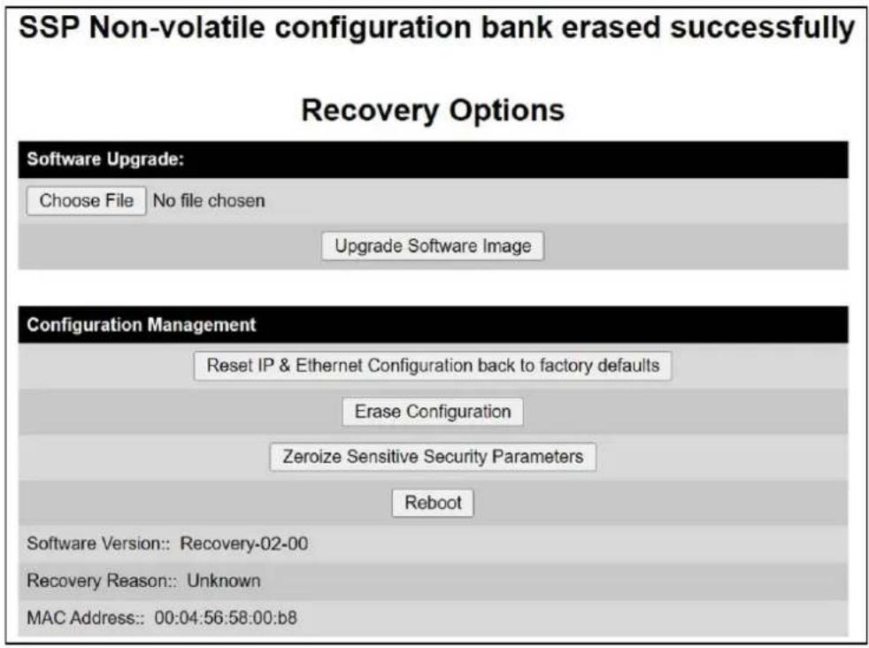
3 Click Reboot. When the "Are you sure you want to REBOOT this unit?" message is displayed, click OK.
4 The unit will now reboot. The unit should now start up in normal mode but with the security configuration reset to default values. If the unit fails to recover, refer to Testing link end hardware on page 8-7 and Cable Diagnostics on page 8-2.

Attention When SSPs have been zeroized, all user accounts are disabled, and the ODU is returned to the "first use" condition. See Creating a user account on page 6-6 to create a new user account for the web-based interface.
Rebooting the unit
Use this option to reboot the unit from the Recovery Options page (Figure 286).
Procedure:
- Click Reboot.
- When the "Are you sure you want to REBOOT this unit?" message is displayed, click OK. The unit will now reboot. The unit should now start up in normal operational mode. If the unit fails to start up, refer to Testing link end hardware on page 8-7.
This chapter contains procedures for identifying and correcting faults in a PTP 700 link. These procedures can be performed either on a newly installed link, or on an operational link if communication is lost, or after a lightning strike.
The following topics are described in this chapter:
- Cable Diagnostics on page 8-2 describes how to perform cable diagnostics test to detect cabling related faults.
- Testing link end hardware on page 8-7 describes how to test the link end hardware, either when it fails on startup, or after a lightning strike.
- Testing the radio link on page 8-13 describes how to test the link when there is no radio communication, or when it is unreliable, or when the data throughput rate is too low.
- Testing PTP-SYNC on page 8-15 describes how to test the PTP-SYNC unit and its connections when the PTP-SYNC LEDs do not illuminate correctly, or when a synchronization fault is suspected.
Cable Diagnostics
This section describes how to diagnose cable faults.
The Cable Diagnostics feature may be used to test Ethernet cables connected to the Main PSU port and the Aux port. The feature uses Time Domain Reflectometry (TDR) technology to test individual twisted pairs in the cable, to identify open circuit and short circuit faults, and indicate the approximate location of the fault:
- Open circuit - An open circuit is detected when the impedance is greater than 300 ohms.
- Short circuit – A short circuit is detected when the impedance is less than 33 ohms.
- Approximate location of the fault - The fault location is reported as a distance from the ODU along the cable, and is accurate to +/- 2 meters (6.5 feet).

Note
- The cable diagnostics results are provided only as a guide.
- The feature reliably detects all open circuit and short circuit faults in cable pairs, but it is not possible to reliably detect short circuit faults between wires in different cable pairs. Except for that specific circumstance, an OK result for all pairs means the cable is good.
• The presence of LPUs can affect the accuracy and reliability of the results.
Before initiating the test, confirm that all outdoor drop cables (that is those that connect the ODU to equipment inside the building) are specified as supported, as defined in Outdoor copper Cat5e Ethernet cable on page 2-28.
Test scenarios
The Cable Diagnostics test may be performed in following scenarios:
| Scenarios | Actions |
| Main PSU port “Down” | Check for physical Ethernet cable connectivity between Power over Ethernet (PoE) and Customer Data Network (or LAN).If the cable connectivity is OK, Perform Cable Diagnostics test. |
| Aux port “Down” | Check for physical Ethernet cable connectivity between ODU and Customer Data Network or Management Agent.If the cable connectivity is OK, Perform Cable Diagnostics test. |
| Main PSU or Aux port is “Up” but the Ethernet speed is noticed slow | There is a possibility that one or more cable pairs have intermittent contact with the RJ45 connector pin. This could result in intermittent communication errors.Follow procedure Ethernet packet test. |
If Ethernet Rx Crc and Align counter is greater than ten (>10), Perform Cable Diagnostics test.
If Packet Error Rate is greater than 1 in 1 million, Perform Cable Diagnostics test.
If Number of lost packets are less than two (<2) after performing Test ping packet loss, perform Cable Diagnostics test.
Otherwise check the ODU's parameter configurations.
Cable Diagnostics test
Menu option: System > Cable Diagnostics
The Cable Diagnostics feature determines a fault in a cable and its approximate location based on Time Domain Reflectometry (TDR).
When the test is initiated for the selected port(s), the ODU sends a known signal (+1V) over the twisted pair cable. The transmitted signal will travel down the cable until it reflects off a fault. The magnitude of the reflection and the time it takes for the reflection to come back can be used to calculate the distance to the fault on the cable. For example, a +1V reflection will indicate an open close to the PHY and a -1V reflection will indicate a short close to the PHY.
Based on the returned signal, the radio identifies the cable status and estimates the distance of the fault. The result of the cable test will be displayed.
The cable diagnostics test can be carried out for Main PSU and AUX ports. This test is not supported for SFP port.

Attention
- On the Main PSU port, the presence of LPUs can affect the accuracy of the cable diagnostics results for some cable configurations. When a fault is detected, the feature reports the distance corresponding to the final TDR signal reflection. In configurations where there is a short cable from the ODU to the first LPU (< 2m), and a moderately long cable to the second LPU (30m), the final TDR signal reflection may come from one of the LPUs itself, rather than the fault. For example, a fault in the first short cable may be reported at or near the second LPU.
- On the Aux port, the presence of LPUs can affect the reliability of the cable diagnostics results for many cable configurations. Frequently, open circuit faults may be reported when the cable is OK, and fault distances may be reported corresponding to the LPU locations. Cable diagnostics tests on the Aux port should be repeated a number of times to establish a pattern.

Note All cable diagnostics results should be verified with an external cable tester before remedial action is taken.
All four twisted pairs of the cable are tested separately, and results are displayed for each pair.
The pin to pair mapping of a cable is shown in Table 254.
Table 254 Pin to pair mapping of a cable (T568B termination)
| Pin | Pair | Wire | Color (Supplied cable) | Color (Conventional) | Pins on plug face |
| 1 | 2 | 1 | Light Orange | White/Orange | 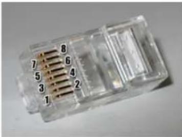 |
| 2 | 2 | 2 | Orange | Orange | |
| 3 | 3 | 1 | Light Green | White/Green | |
| 4 | 1 | 2 | Blue | Blue | |
| 5 | 1 | 1 | Light Blue | White/Blue | |
| 6 | 3 | 2 | Green | Green | |
| 7 | 4 | 1 | Light Brown | White/Brown | |
| 8 | 4 | 2 | Brown | Brown |
Procedure
1 Select ports for cable diagnostics test:
Cable Diagnostics
This feature uses Time Domain Reflectometry (TDR) technology to identify open circuit and short circuit faults in individual twisted pairs of Ethernet cables connected to the Main PSU port and the Aux port, and indicate the approximate distance to the fault
| Attributes | Value | Units |
| Cable Diagnostics Ports | ✓ Main PSU Port | |
| □ Aux Port | ||
| Start Test | ||
2 Click "Start Test" button to begin the test:
Start Test
3 The confirmation pop up box is displayed. Click the "OK" button to proceed with the test:


Note The Local Management port connection will be lost when the local management port is under test. However, the management port will be accessible when the other ports are under test.
4 On completion of the test, the web page is refreshed automatically, and the results are displayed:
Cable Diagnostics Results
The cable diagnostics results are provided only as a guide. The presence of LPUs can affect the accuracy and reliability of the results (see the User Guide for more details).

All cable diagnostics results should be verified with an external cable tester before remedial action is taken.
Main PSU Port
| Attributes | Value | Units | |
| Last Test Time | 01-Jan-1970 00:06:53 | ||
| Cable Pair | Results | Distance to Fault | Units |
| Pair 1 | Short Circuit | 6 | meters |
| Pair 2 | OK | ||
| Pair 3 | OK | ||
| Pair 4 | Short Circuit | 6 | meters |
Aux Port
| Attributes | Value | Units | |
| Last Test Time | |||
| Cable Pair | Results | Distance to Fault | Units |
| Pair 1 | Not Tested | ||
| Pair 2 | Not Tested | ||
| Pair 3 | Not Tested | ||
| Pair 4 | Not Tested |

Note The last test performed results are shown for user reference purpose.
Table 255 Cable Diagnostics attributes
| Attribute | Meaning |
| Cable Diagnostics Ports | Select ports on which Cable Diagnostics must be executed. |
| Last Test Time | The date and time when a Cable Diagnostics test was last executed successfully. |
| Cable Pair | The result of the most recent execution of cable diagnostics on a cable pair.There are four twisted pairs in each Cat5 cable. The cable diagnostics test is performed on each pair of the cable. |
| Results | OK: Reported when the test is passed for a respective cable pair.Open Circuit: Reported when the impedance is greater than 330 ohms.Short Circuit: Reported when impedance is less than 33 ohms. |
| Distance | The estimate of the distance from the ODU to the fault detected on the cable pair during the most recent execution of Cable Diagnostics.Fault in cables longer than 160 meters (525 feet) may not be detected.The error margin is +/- 2 meters (6.5 feet). |
| Units | Unit of cable length in meters. |
Testing link end hardware
This section describes how to test the link end hardware when it fails on startup or during operation.
Before testing link end hardware, confirm that all outdoor drop cables, that is those that connect the ODU to equipment inside the building, are of the supported type, as defined in Outdoor copper Cat5e Ethernet cable on page 2-28.
AC+DC Enhanced Power Injector 56V LED sequence
For the AC+DC Enhanced Power Injector 56V, the expected power-up LED sequence is:
- The Power (green) LED illuminates steadily.
• After about 45 seconds, the Ethernet (yellow) LED blinks slowly 10 times.
• The Ethernet (yellow) LED illuminates steadily, then blinks randomly to show Ethernet activity.
If this sequence does not occur, take appropriate action depending on the LED states:
• Power LED is off on page 8-7
• Power LED is blinking on page 8-7
- Ethernet LED did not blink 10 times on page 8-8
- Ethernet LED blinks ten times then stays off on page 8-8
- Ethernet LED blinks irregularly on page 8-9 (for example a short blink followed by a long blink)
• Power LED is on, Ethernet LED blinks randomly on page 8-9
If a fault is suspected in the ODU-PSU drop cable, perform Test resistance in the drop cable on page 5-26.
Power LED is off
Meaning: Either the PSU is not receiving power from the AC/DC outlet, or there is a wiring fault in the ODU cable.
Action: Remove the ODU cable from the PSU and observe the effect on the Power LED:
- If the Power LED does not illuminate, confirm that the mains power supply is working, for example, check the plug and fuse (if fitted). If the power supply is working, report a suspected PSU fault to Cambium Networks.
• If the Power LED does illuminate, perform Test resistance in the drop cable on page 5-26.
Power LED is blinking
Meaning: The PSU is sensing there is an overload on the ODU port; this could be caused by a wiring error on the drop cable or a faulty ODU.
Action: Remove the ODU cable from the PSU. Check that pins 4&5 and 7&8 are not crossed with pins 1&2 and 3&6. Check that the resistance between pins 1&8 is greater than 100K ohms. If either check fails, replace or repair the ODU cable.
Ethernet LED did not blink 10 times
Meaning: The ODU flashes the LED on the AC+DC Enhanced Power Injector 56V 10 times to show that the ODU is powered and booted correctly.
Action:
1 Remove the ODU cable from the PSU. Examine it for signs of damage. Check that the ODU cable resistances are correct, as specified in Test resistance in the drop cable on page 5-26. If the ODU cable is suspect, replace it.
2 Use the LPU (if installed) to check that power is available on the cable to the ODU. Access the connections by rotating the LPU lid as shown (slacken the lid nut but do not remove it):

4 Check that test point P1 on the LPU PCB corresponds to pin 1 on the RJ45. Repeat for points P2 to P8. This test is only valid if both the PSU and the ODU are disconnected.
5 Reconnect the ODU cable to the PSU.
6 Check that the PWR LED near the top right of the LPU PCB is illuminated to indicate power in the Ethernet cable.
7 If any test fails, replace or repair the cable that connects the PSU to the LPU or ODU.
Ethernet LED blinks ten times then stays off
Meaning: There is no Ethernet traffic between the PSU and ODU.
Action: The fault may be in the LAN or ODU cable:
- Confirm that Ethernet traffic is connected to the AC+DC injector LAN port, confirm the cable is not faulty, replace if necessary.
- If the LAN connection to the AC+DC Power Injector 56V is working, check the drop cable is correctly wired using a suitable cable tester. Repeat the drop cable tests on page Test resistance in the drop cable on page 5-26.
Ethernet LED blinks irregularly
Meaning: If the Ethernet LED blinks irregularly, for example two rapid blinks followed by a longer gap, this indicates that the ODU has booted in recovery mode. The causes may be: installation wiring, or a corrupt ODU firmware load, or sufficient time has not been allowed between a repeat power up.
Action: Refer to Recovery mode on page 7-80.
Power LED is on, Ethernet LED blinks randomly
Meaning: Both LEDs are in their normal states, implying that the PSU is receiving power from the AC/DC outlet and there is normal Ethernet traffic between the PSU and ODU.
Action: If, in spite of this, a fault is suspected in the link end hardware:
- If the Ethernet connection to the network is only 100BASE-TX, when 1000BASE-T is expected: remove the ODU cable from the PSU, examine it, and check that the wiring to pins 4&5 and 7&8 is correct and not crossed.
• Perform Ethernet packet test on page 8-10.
Ethernet packet test
Follow the Ethernet packet test flowchart (Figure 287) and procedures below.
Figure 287 Ethernet packet test flowchart
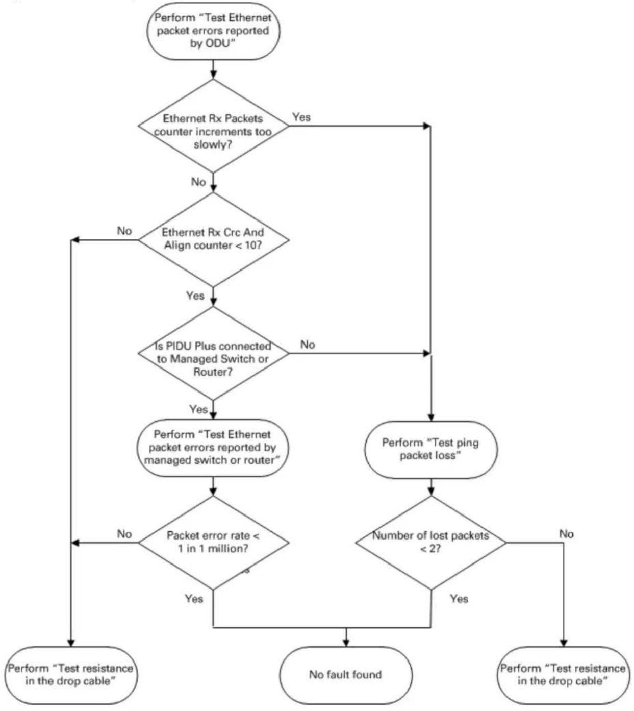
flowchart
graph TD
A["Perform "Test Ethernet packet errors reported by ODU""] --> B{Ethernet Rx Packets counter increments too slowly?}
B -->|Yes| C["Perform "Test resistance in the drop cable""]
B -->|No| D{Ethernet Rx Crc And Align counter < 10?}
D -->|Yes| E{Is PIDU Plus connected to Managed Switch or Router?}
D -->|No| F["Perform "Test ping packet loss""]
E -->|Yes| G["Perform "Test Ethernet packet errors reported by managed switch or router""]
E -->|No| H{Packet error rate < 1 in 1 million?}
G --> I["Perform "Test resistance in the drop cable""]
H --> J{Number of lost packets < 2?}
J -->|Yes| K["Perform "Test resistance in the drop cable""]
J -->|No| L["Perform "Test resistance in the drop cable""]
K --> M["No fault found"]
L --> N["Perform "Test resistance in the drop cable""]
C --> B
D --> E
E --> G
G --> I
I --> J
Test Ethernet packet errors reported by ODU
Log into the unit and click Administration, Statistics, Detailed Counters. Click Reset System Counters at the bottom of the page and wait until the Ethernet Rx Packets counter has reached 1 million (the count will only update when the page is refreshed. If the counter does not increment or increments too slowly, because for example the PTP 700 is newly installed and there is no offered Ethernet traffic, then abandon this procedure and consider using the procedure Test ping packet loss on page 8-11.
Read the Ethernet Rx Crc And Align counter. The test has passed if this is less than 10.
Test Ethernet packet errors reported by managed switch or router
If the ODU is connected to a managed Ethernet switch or router, it may be possible to monitor the error rate of Ethernet packets. Please refer to the user guide of the managed network equipment. The test has passed if the rate of packet errors reported by the managed Ethernet switch or router is less than 10 in 1 million packets.
Test ping packet loss
Using a computer, it is possible to generate, and monitor packets lost between the PSU and the ODU. This can be achieved by executing the Command Prompt application which is supplied as standard with Windows and MAC operating systems.

Attention This procedure disrupts network traffic carried by the PTP 700 under test:
Procedure:
1 Ensure that the IP address of the computer is configured appropriately for connection to the PTP 700 under test, and does not clash with other devices connected to the network.
2 If the PSU is connected to an Ethernet switch or router then connect the computer to a spare port, if available.
3 If it is not possible to connect the computer to a spare port of an Ethernet switch or router, then the PSU will need to be disconnected from the network in order to execute this test:
- Disconnect the PSU from the network.
- Connect the computer directly to the LAN port of the PSU.
4 On the computer, open the Command Prompt application.
5 Send 1000 ping packets of length 1500 bytes. The process will take 1000 seconds, which is approximately 17 minutes.
If the computer is running a Windows operating system, this is achieved by typing (for an IPv6 address, use the ping6 command):
ping -n 1000 -l 1500
where
If the computer is running a MAC operating system, this is achieved by typing:
ping -c 1000 -s 1492
where
6 Record how many Ping packets have been lost. This is reported by Command Prompt on completion of the test.
The test has passed if the number of lost packets is less than 2.
Testing the radio link
This section describes how to test the link when there is no radio communication, when it is unreliable, when the data throughput rate is too low, or when a unit is causing radio or TV interference. It may be necessary to test the units at both ends of the link.
No activity
If there is no wireless activity, proceed as follows:
1 Check for Alarm conditions on Home page.
2 Check that the firmware at each end of the link is the same version.
3 Check that the Target Mac address is correctly configured at each end of the link.
4 Check Range.
5 Check Tx Power.
6 Check License keys to ensure that both units are the same product variant.
7 Check Master/Slave status for each unit and ensure that one unit is Master and the other unit is slave.
8 Check that the link is not obstructed or the ODU misaligned.
9 Check the DFS page at each end of the link and establish that there is a quiet wireless channel to use.
10 If there are no faults found in the configuration and there is absolutely no wireless signal, retry the installation procedure.
11 If this does not work then report a suspected ODU fault to Cambium Networks.
Some activity
If there is some activity but the link is unreliable or does not achieve the data rates required, proceed as follows:
1 Check that the interference has not increased using the DSO measurements.
2 If a quieter channel is available check that it is not barred.
3 Check that the path loss is low enough for the communication rates required.
4 Check that the ODU has not become misaligned.
Radio and television interference
If a PTP 700 unit is interfering with radio or television reception (this can be determined by turning the equipment off and on), attempt the following corrective actions:
- Realign or relocate the antenna.
- Increase the separation between the affected equipment and antenna.
- Connect the ODU and PSU power supply into a power outlet on a circuit different from that to which the receiver is connected.
- Contact Cambium Point-to-Point for assistance.
Testing PTP-SYNC
This section describes how to test the PTP-SYNC unit and its connections when the PTP-SYNC LEDs do not illuminate correctly, or when a synchronization fault is suspected.
Checking the PTP-SYNC LEDs
If a fault is suspected in the PTP-SYNC or GPS hardware, check the PTP-SYNC LED states and use Table 256 to choose the correct test procedure.
Table 256 PTP-SYNC indicator LED states
| LED | State | Description and test procedure |
| GPS | Off | No GPS satellite data being received at the GPS/SYNC IN port. Refer to GPS LED does not illuminate or blink on clustered units on page 8-16. |
| On steady or blink | GPS satellite data being received. | |
| SYNC | Off | No data being received at the SYNC OUT port. |
| On steady or blink | Data being received at the SYNC OUT port.The SYNC LED does not normally illuminate, even in cluster configurations. | |
| STATUS | Off | No power. Refer to LEDs do not illuminate on page 8-15. |
| On steady | Power but no satellite lock. Refer to STATUS LED is on steady on page 8-16. | |
| Blink | Power and satellite lock at either the GPS/SYNC IN or 1PPS IN port. | |
| Double blink | Possible fault in GPS/SYNC IN or 1PPS IN cables. Refer to STATUS LED double-blinks on page 8-16. | |
| ODU | Off | No signal being received from the ODU. Refer to ODU LED does not illuminate within 90 seconds on page 8-16. |
| On | Communication with the ODU is established. | |
| Blink red | Error in communication with ODU. Refer to ODU LED blinks red on page 8-16, |
LEDs do not illuminate
Meaning: The PTP-SYNC unit is not powered up.
Action: Ensure that there is a cable connection between the PSU ODU interface and the PIDU IN interface of the PTP-SYNC unit. Confirm that the PSU is powered up.
STATUS LED is on steady
Meaning: There is power but no satellite lock. This probably indicates that a 1PPS synchronization pulse is not detected by the PTP-SYNC unit.
Action: Depending on system configuration, take one of the following actions:
- System using a GPS receiver module - Ensure that there is a cable connection between the PTP-SYNC GPS/SYNC IN interface and the LPU, also that there is a cable connection between the LPU and the GPS receiver module. Check that the GPS receiver module has an uninterrupted view of the sky.
- System using an alternative 1PPS timing source - Ensure that there is a cable connection between the PTP-SYNC GPS/SYNC IN or 1PPS IN interface and the 1PPS timing source.
- On cluster slave units – Ensure that there is a cable connection between the slave GPS/SYNC IN interface and the SYNC OUT interface of the preceding unit in the chain.
STATUS LED double-blinks
Meaning: There may be a fault in the GPS/SYNC IN or 1PPS IN cables.
Action: Check the GPS wiring in accordance with Table 47.
ODU LED does not illuminate within 90 seconds
Meaning: There may be no communication between PTP-SYNC and ODU.
Action: Ensure that the PTP-SYNC ODU OUT interface is connected to the ODU (and LPUs if installed) via the drop cable.
ODU LED blinks red
Meaning: Error in communication with ODU. Possible causes are: fault in the ODU or PSU cable, maximum recommended cable lengths exceeded, or TDD synchronization is not enabled at the ODU.
Action: Confirm that the ODU and PSU cables are not too long: see Ethernet standards and cable lengths on page 2-27. Check the ODU cable wiring by following the procedure described in Test resistance in the drop cable on page 5-26.
GPS LED does not illuminate or blink on clustered units
Meaning: This indicates a fault only when the timing source is a GPS receiver.
Action: Table 257 describes the action to be taken depending upon the behavior of the GPS LEDs at the master and slave(s).
Table 257 Clustered PTP-SYNC units - GPS LEDs Fault-finding
| Cluster timing source | GPS LED on master | GPS LED on slave(s) | Diagnosis |
| GPS receiver providing NMEA data | Blink | Blink | OK |
| Off | Any | Fault in GPS unit or GPS cable | |
| Blink | Off | Fault in daisy chain cable | |
| Alternative 1PPS source, no NMEA data | Off | Off | OK |
| Off | On | Fault in alternative 1PPS source | |
| One ODU is cluster timing master | Off | Off | OK |
Glossary
| Term | Definition |
| AES | Advanced Encryption Standard |
| ANSI | American National Standards Institution |
| ARP | Address Resolution Protocol |
| ATPC | Automatic Transmit Power Control |
| Aux | Auxiliary |
| BBDR | Broadband Disaster Relief |
| BPSK | Binary Phase Shift Keying |
| BW | Bandwidth |
| CFM | Connection Fault Management |
| CHAP | Challenge Handshake Authentication Protocol |
| CSP | Critical Security Parameter |
| DC | Direct Current |
| DER | Distinguished Encoding Rules |
| DES | Data Encryption Standard |
| DFS | Dynamic Frequency Selection |
| DHCP | Dynamic Host Configuration Protocol |
| DNS | Domain Name Server |
| DSCP | Differentiated Services Code Point |
| DSO | Dynamic Spectrum Optimization |
| EAPS | Ethernet Automatic Protection Switching |
| EIRP | Equivalent Isotropic Radiated Power |
| EMC | Electromagnetic Compatibility |
| EMD | Electro-Magnetic Discharge |
| EPL | Ethernet Private Line |
| ETSI | European Telecommunications Standards Institute |
| EU | European Union |
| FAQ | Frequently Asked Question |
| FCC | Federal Communications Commission |
| FIPS | Federal Information Processing Standards |
| FQDN | Fully Qualified Domain Name |
| GARP | Generic Attribute Registration Protocol |
| GE | Gigabit Ethernet |
| GUI | Graphical User Interface |
| HTTP | Hypertext Transfer Protocol |
| IB | In-Band |
| IC | Industry Canada |
| ICMP | Internet Control Message Protocol |
| ICNIRP | International Commission on Non-Ionizing Radiation Protection |
| IEEE | Institute of Electrical and Electronic Engineers |
| IP | Internet Protocol |
| IPSec | Internet Protocol Security |
| ISM | Industrial Scientific and Medical |
| ITPE | Initial Transmit Power Estimate |
| KDB | Knowledge Database |
| L2CP | Layer Two Control Protocols |
| LACP | Link Aggregation Control Protocol |
| LLDP | Link Layer Discovery Protocol |
| LAN | Local Area Network |
| LOS | Line-of-Sight (clear line-of-sight, and Fresnel zone is clear) |
| LPU | Lightning Protection Unit |
| MAC | Medium Access Control Layer |
| MDI (-X) | Medium Dependent Interface (-Crossover) |
| MEF | Metro Ethernet Forum |
| MIB | Management Information Base |
| MIMO | Multiple-Configure Multiple-Output |
| MLD | Multicast Listener Discovery |
| MPLS | Multiprotocol Label Switching |
| MRP | Multiple Registration Protocol |
| MSTP | Multiple Spanning Tree Protocol |
| MTU | Maximum Transmission Unit |
| NA | Neighbor Advertisement |
| NLOS | Non-Line-of-Sight |
| NMEA | National Marine Electronics Association |
| NS | Neighbor Solicitation |
| NTP | Network Time Protocol |
| NUD | Neighbor Un-reachability Detection |
| ODU | Outdoor Unit |
| OFDM | Orthogonal Frequency Division Multiplex |
| OOB | Out-of-Band |
| PC | IBM Compatible Personal Computer |
| PIDU | Powered Indoor Unit |
| POE | Power over Ethernet |
| PSU | Power Supply Unit |
| PTP | Point-to-Point |
| QAM | Quadrature Amplitude Modulation |
| QoS | Quality of Service |
| QPSK | Quadrature Phase Shift Keying |
| R-APS | Ring Automatic Protection Switching |
| RADIUS | Remote Authentication Dial-In Service |
| RAM | Random Access Memory |
| RF | Radio Frequency |
| RFC | Request for Comments |
| RoW | Rest of World |
| RMA | Return Material Authorization |
| RSSI | Received Signal Strength Indication |
| RSTP | Rapid Spanning Tree Protocol |
| SAN | Subject Alternative Name |
| SELV | Safety Extra Low Voltage |
| SFP | Small Form-factor Pluggable |
| SLAAC | Stateless Address Auto-configuration |
| SMTP | Simple Mail Transport Protocol |
| SNMP | Simple Network Management Protocol |
| SNTP | Simple Network Time Protocol |
| SSO | Single Sign On |
| SSP | Sensitive Security Parameters |
| STP | Spanning Tree Protocol |
| Syslog | System Logging |
| TC | Traffic Class |
| TCP | Transmission Control Protocol |
| TDD | Time Division Duplexing |
| TDM | Time Division Multiplexing |
| TDWR | Terminal Doppler Weather Radar |
| TGB | Tower Ground Bus bar |
| TLS | Transport Layer Security |
| UNII | Unlicensed National Information Infrastructure |
| URL | Universal Resource Location |
| USM | User-based Security Model |
| UTC time | Coordinated Universal Time |
| UTP | Unshielded Twisted Pair |
| UV | Ultraviolet |
| VACM | View-based Access Control Model |
| VLAN | Virtual Local Area Network |
| WEEE | Waste Electrical and Electronic Equipment |
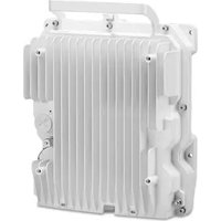
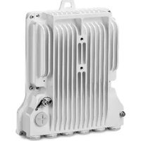

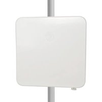
- Cambium Networks™
- USER GUIDE
- Reservation of Rights
- Copyrights
- Restrictions
- License Agreements
- About This User Guide....1
- Important regulatory information....3
- Problems and warranty ....5
- Security advice 6
- Precautionary statements....7
- Caring for the environment....8
- Chapter 1: Product description....1-1
- Overview of the PTP 700 Series....1-2
- Wireless topology....1-8
- Wireless interface 1-12
- TDD synchronization 1-21
- CONTENTS
- Contacting Cambium Networks
- Purpose
- Cross references
- Feedback
- Important regulatory information
- Complying with rules for the country of operation
- Radar avoidance
- Application firmware
- External antennas
- Ethernet networking skills
- Lightning protection
- Training
- Problems and warranty
- Reporting problems
- Repair and service
- Hardware warranty
- Security advice
- Precautionary statements
- Warning
- Attention
- Note
- Caring for the environment
- In EU countries
- In non-EU countries
- Overview of the PTP 700 Series
- Key features
- Frequency bands
- Typical bridge deployment
- Hardware overview
- Protected links
- Wireless topology
- PTP topology
- HCMP topology
- Hot Standby (1+1) link protection
- Protection state
- Channel bandwidth
- RF combiners
- 2+0 link protection
- Wireless interface
- Orthogonal Frequency Division Multiplexing (OFDM)
- Time slots
- OFDM and channel bandwidth
- Adaptive modulation
- MIMO
- Spatial diversity
- Time division duplexing in PTP wireless topology
- TDD frame parameters
- Channel selection
- Time division duplexing in Hot Standby (1+1) link protection
- Burst duration
- Capacity
- Time division duplexing in HCMP wireless topology
- TDD cycle
- TDD synchronization
- PTP-SYNC
- Direct connection between two ODUs
- Configuring the TDD frame
- Link capacity in synchronized networks
- Links in Hot Standby
- Wireless resource allocation
- License keys and regulatory bands
- Spectrum management
- Spectrum management measurements
- Measurement analysis
- Statistical summary
- RF channel selection
- Fixed frequency
- Dynamic spectrum optimization
- Null Steering
- Fixed Frequency Mode
- DSO Mode
- Slave scan in HCMP
- Barring channels at the Slave ODU
- Force scan
- Auto optimum slave scan
- Auto optimum selection method
- Establishing a link
- Link mode optimization
- IP link optimization in the PTP topology
- TDM link optimization in the PTP topology
- Link optimization in the HCMP topology
- Link symmetry
- PTP topology without TDD Synchronization
- PTP topology with TDD Synchronization
- HCMP topology with Standard TDD Frame Configuration
- HCMP topology with Expert TDD Frame Configuration
- Dynamic time slot allocation in HCMP
- Standard TDD Frame Configuration
- Expert TDD Frame Configuration
- Automatic alignment
- Beam Steering ODU
- Supported features when automatic alignment is disabled
- Supported features when automatic alignment is enabled
- Installation with automatic alignment
- Operation of installed link
- Interworking between ODU platform variants
- TD-90 antenna positioner
- SFP interface
- Transmission of alignment messages
- Using the Beam Steering ODU with TD-90
- Wireless encryption
- Access method
- Encryption options
- TLS RSA
- Authentication using TLS RSA
- Authorization using TLS RSA with Link Access
- Authorization using TLS RSA with Group Access
- Negotiation of TLS RSA key size
- TLS PSK 128-bit and TLS PSK 256-bit
- Over the air rekeying
- Designing PTP networks
- Using Dynamic Spectrum Optimization
- Using frequency planning
- Synchronized networks
- Ethernet bridging
- Ethernet ports
- Data and management services
- Ethernet switching
- Port Allocation
- MAC Filtering
- Disabling MAC Filtering
- Data Service
- Transparent Ethernet service
- Layer two control protocols
- Quality of service for bridged Ethernet traffic
- Fragmentation
- Data port wireless link down alert
- Lowest Data Modulation Mode
- Out-of-Band Management Service
- Management port wireless Down Alert
- Link protection
- Ethernet switches
- Data bridging in the PTP link
- Mapping of Data and Management services
- TD-90 Service
- Protocol model
- Synchronous Ethernet
- IEEE 1588-2008 Transparent Clock
- TDM bridging
- System management
- Management agent
- Application layer protocols
- IP interface for NMS
- IP interface for TD-90
- Network management
- IPv4 and IPv6 interfaces for NMS
- MAC address
- VLAN membership
- Ethernet and DSCP priority
- Access to the management agent
- MAC address and IP address of the management agent
- IPv6
- Neighbor discovery
- Path MTU discovery and packet size
- ICMP for IPv6
- Addressing
- Privacy extensions
- DHCPv6
- Multicast listener discovery for IPv6
- Textual representation of IPv6 addresses
- Security
- cnMaestro device agent
- Critical security parameters
- Configuration templates
- Web server
- Web interfaces
- Web pages in the simplified interface
- Web pages in the standard interface
- Transport layer security
- Web management authentication
- Locally-authenticated role-based authentication
- Locally-authenticated identity-based user accounts
- Remote authentication using RADIUS
- Remote authentication using Single Sign On method
- SNMP control of passwords
- SNMP
- Standard MIBs
- Enterprise MIB
- SNMP Configuration Mode
- Standalone management of TD-90
- Integrated management of TD-90
- SNMP Proxy
- Offline configuration
- SNMP Agent for antenna alignment
- IP interface
- Discovery
- System Clock
- SNMPv3 security
- SNMP Engine ID
- User-based security model
- View-based access control model
- Access to sensitive security parameters
- MIB-based management of SNMPv3 security
- Web-based management of SNMPv3 security
- Downgrade of the license key
- System logging (syslog)
- Domain Name Service (DNS)
- Instant messaging
- AES license
- Firmware upgrade
- Transition of digital signature algorithms
- Capability upgrades
- Full capability trial period
- Recovery mode
- Recovery mode options
- Upgrade from earlier releases
- FIPS 140-3 mode
- FIPS 140-3 approved mode
- Enforced configuration in FIPS approved mode
- Secure mode alarm
- Security configuration for FIPS approved mode
- Exiting from the FIPS operational state
- Reverting to the standard (non-FIPS) mode
- Outdoor unit (ODU)
- ODU description
- Hardware platform variants
- Regional variants
- Capacity variants
- PTP 45700 Connectorized+Integrated ODU
- Capacity and capability licensing
- Individual ODU part numbers
- PTP 700 Lite
- ODU kit part numbers
- PTP 45700 Connectorized ODU
- PTP 45700 Beam Steering ODU
- Capability licensing
- PTP 78700 Integrated ODU
- PTP 78700 Connectorized ODU
- ODU capability upgrades
- ODU accessories
- ODU cables
- ODU mounting brackets
- ODU interfaces
- ODU mechanical specifications
- Power supply units (PSU)
- AC+DC Enhanced Power Injector 56V
- PSU description
- PSU part numbers
- PSU specifications
- Antennas and antenna cabling
- Antenna requirements
- RF cable and connectors
- Antenna accessories
- RF Combiner Kit
- RF Combiner specifications
- Ethernet cabling
- Ethernet standards and cable lengths
- Outdoor copper Cat5e Ethernet cable
- Cable grounding kit
- Lightning protection unit (LPU) and grounding kit
- LPU for GPS drop cables
- RJ45 connectors and spare glands
- Cable hoisting grip
- Indoor Cat5e cable
- SFP module kits
- Optical cable and connectors
- PTP-SYNC unit
- PTP-SYNC unit description
- PTP-SYNC part numbers
- PTP-SYNC unit interfaces
- PTP-SYNC specifications
- Signal polarities
- GPS receivers
- Trimble Acutime™ GG GPS receiver for PTP-SYNC
- GPS receiver part numbers
- Twelve way circular connector
- Typical deployment
- ODU with POE interface to PSU
- SFP and Aux Ethernet interfaces
- GPS receiver interfaces
- Site planning
- Grounding and lightning protection
- Lightning protection zones
- Site grounding system
- ODU and external antenna location
- ODU ambient temperature limits
- ODU wind loading
- Hazardous locations
- PSU DC power supply
- PSU AC power supply
- PSU location
- PTP-SYNC location
- GPS receiver location
- Mounting the GPS receiver module on the equipment building
- Mounting the GPS receiver module on a metal tower or mast
- Drop cable grounding points
- LPU location
- Multiple LPUs
- Hot Standby
- Radio spectrum planning
- General wireless specifications
- Regulatory limits
- Conforming to the limits
- Available spectrum
- Frequency selection
- PTP topology in regions with mandatory radar detection
- Frequency selection for HCMP topology
- Frequency selection for PTP links used in 2+0 configuration
- Link planning
- LINKPlanner
- Range and obstacles
- LoS links in radar regions
- LINKPlanner for synchronized networks
- Path loss
- Calculating data rate capacity
- Calculation procedure for PTP topology with TDD synchronization
- Calculation procedure for PTP topology with long frame duration
- Calculation procedure for HCMP topology with standard TDD frame
- Calculation example for HCMP topology with standard TDD frame
- Suppose that:
- Calculation procedure for HCMP topology with expert mode TDD frame
- Planning for connectorized units
- When to install connectorized units
- Antenna gain in PTP topology
- Spatial diversity in PTP topology
- Choosing external antennas
- Protected links with shared antenna
- Link configurations for protection and spatial diversity
- Unprotected links
- End configurations for spatial diversity
- Configuration options for TDD synchronization
- Using PTP-SYNC with PTP 45700
- Single PTP link or HCMP sector configuration with PTP-SYNC
- Cluster with PTP-SYNC and GPS receiver
- Cluster with PTP-SYNC and no GPS receiver
- Using a direct connection between ODUs
- Aux Port to Aux Port
- TDD burst durations in PTP topology
- TDD frame durations
- TDD frame design for standalone synchronization
- TDD frame design for network-wide synchronization
- Data network planning
- Ethernet port allocation
- Services
- Port allocation rules
- Mapping of ports and services
- Additional port allocation rules
- Priority for management traffic
- IP interface for integrated TD-90 management
- Layer 2 control protocols
- Priority schemes
- Ethernet priority scheme
- IP/MPLS priority scheme
- "Daisy-chaining" PTP 700 links
- Green Ethernet switches
- Network management planning
- Planning for cnMaestro
- Standard templates in the simplified web interface
- Custom templates in the simplified web interface
- Planning for SNMP operation
- Supported MIBs
- Supported notifications
- Supported diagnostic alarms
- Enabling SNMP
- Transactional model
- Planning for Domain Name Service (DNS)
- Hot Standby links
- Security planning
- License key digital signature
- Planning for SNTP operation
- Using the Security Wizard
- Planning for wireless encryption
- Encryption algorithms
- TLS-RSA
- TLS-PSK
- Planning for HTTPS/TLS operation
- Planning for protocols and ports
- Planning for SNMPv3 operation
- SNMPv3 default configuration (MIB-based)
- VACM default configuration
- Planning for RADIUS operation
- RADIUS attributes
- Planning for Single Sign-On (SSO) Operation
- Configuration requirements
- Assertions
- User role mapping
- Important considerations
- Internally-generated random keys
- Planning for FIPS 140-3 operation
- System threshold, output power and link loss
- Connectorized+Integrated ODUs
- Connectorized and Beam Steering ODUs
- Data throughput capacity tables
- Data capacity in PTP topology
- Time slots per frame in PTP topology with synchronization
- PTP topology with long frame duration
- Frame duration in HCMP topology with standard configuration
- Frame duration in HCMP topology with expert configuration
- Capacity per time slot
- Chapter 4: Regulatory information
- Compliance with safety standards
- Electrical safety compliance
- Electromagnetic compatibility (EMC) compliance
- Human exposure to radio frequency energy
- Power density exposure limit
- Calculation of power density
- Where:
- Calculated distances
- Compliance with radio regulations
- Safety
- Power lines
- Working at heights
- PSU
- Grounding and protective earth
- AC supply
- DC supply
- Powering down before servicing
- Primary disconnect device
- External cables
- Drop cable tester
- Grounding PTP-SYNC
- RF exposure near the antenna
- Minimum separation distances
- Grounding and lightning protection requirements
- Grounding cable installation methods
- Siting ODUs and antennas
- Thermal Safety
- ODU variants and mounting bracket options
- Mounting bracket options
- Installing the ODU and top LPU
- Attach ground cables to the ODU
- Mount the ODU on the mast
- Tilt Bracket Assembly
- Tilt Bracket Assembly with band clamps
- Heavy Duty Mounting bracket (Integrated)
- Smart Antenna Clamp Set
- Mount the top LPU
- Install external antennas
- Install RF Combiners
- Assemble and mount the RF Combiners
- Installing the copper Cat5e Ethernet interface
- Install the ODU to top LPU drop cable
- Disconnect the drop cable from the LPU or ODU
- Install the main drop cable
- Cut to length and fit hoisting grips
- Ground the main drop cable
- Install the bottom LPU to PSU drop cable
- Install the bottom LPU
- Install the LPU to PSU drop cable
- Test resistance in the drop cable
- Installing the PSU
- Installing the AC+DC Enhanced Power Injector 56V
- Installing a PTP-SYNC unit
- Mounting the PTP-SYNC unit
- Connecting up the PTP-SYNC unit
- Powering up the PTP-SYNC installation
- Installing the Trimble Accutime GPS receiver
- Mounting the GPS receiver
- Preparing the GPS drop cable
- Assembling an RJ45 plug and housing for GPS
- Install the RJ45 crimp plug.
- Assemble plug housing:
- Check the assembly. This is an example of an assembled plug housing on the end of a drop cable:
- Assembling a 12 way circular connector
- Connecting the GPS drop cable
- Top grounding point for GPS adapter cable
- Installing and connecting the GPS LPU
- Installing an SFP Ethernet interface
- Fitting the long cable gland
- Inserting the SFP module
- Connecting the cable
- Fitting the gland
- Removing the cable and SFP module
- Installing an Aux Ethernet interface
- Supplemental installation information
- Stripping drop cable
- Creating a drop cable grounding point
- Weatherproofing an N type connector
- Replacing PSU fuses
- Preparing for configuration and alignment
- Safety precautions
- Regulatory compliance
- Selecting configuration options
- Generating license keys
- Connecting to the unit
- Configuring the management PC
- Procedure:
- Connecting to the PC and powering up
- Using the web interface
- Creating a user account
- Logging into the web interface
- Using the menu options for the standard web interface
- Using the menu options for the simplified web interface
- Standard Installation menu
- Starting the Installation Wizard
- Disarm Installation page
- Disarm Installation
- Current Installation Summary page
- Current Installation Summary
- Software License Key page
- Software License Key
- Procedures:
- Full capacity trial
- Changing AES license
- Wireless Topology Configuration page
- Interface Configuration page
- Interface Configuration
- Configuring port allocations
- Management Configuration page
- Wireless Configuration page
- Wireless Configuration
- TDD Frame page
- TDD Frame
- TDD Synchronization page (optional)
- Confirm Installation Configuration page
- Simplified Installation menu
- Equipment Configuration page
- Equipment Configuration
- Template Configuration page
- Confirm Installation Configuration
- System menu
- System Configuration page
- LAN Configuration page
- LAN Configuration
- QoS Configuration page
- QoS Configuration
- SFP Configuration page
- SFP Configuration
- Authorization Control page
- Save and Restore Configuration page
- Save & Restore Configuration
- Reset Configuration page
- Software Upgrade page
- Preparation:
- Software Upgrade: Are You Sure?
- Current software image description
- Uploaded software image description
- Software Upgrade Complete
- Management menu
- Web-Based Management page
- Local User Accounts page
- RADIUS Configuration page
- SSO Configuration page
- Webpage Properties page
- Email Configuration page
- Instant Messaging page
- Diagnostic Alarms page
- Time Configuration page
- Syslog Configuration page
- SNMP pages (for SNMPv3)
- Current SNMP Summary (for SNMPv3)
- Step 1: SNMP Configuration (for SNMPv3)
- Step 2: SNMP MIB-II System Objects (for SNMPv3)
- Step 3: SNMP User Policy Configuration (for SNMPv3)
- Step 4: SNMP User Accounts Configuration (for SNMPv3)
- Step 5: SNMP Trap Configuration (for SNMPv3)
- Confirm SNMP Configuration (for SNMPv3)
- SNMP pages (for SNMPv1/2c)
- Current SNMP Summary (for SNMPv1/2c)
- Step 1: SNMP Configuration (for SNMPv1/2c)
- Step 2: SNMP MIB-II System Objects (for SNMPv1/2c)
- Step 3: SNMP Trap Configuration (for SNMPv1/2c)
- Confirm SNMP Configuration (for SNMPv1/2c)
- Template Manager
- Create Template
- Import Template
- Export Template
- Delete Template
- Security menu
- Preparation
- Security Configuration Wizard page
- Security Configuration Wizard
- Security options
- Key of Keys
- Entropy
- Enter User Security Banner
- Enter Login Information Settings
- Enter HTTPS Configuration
- Configure Wireless Security
- Enter Wireless Link Encryption Settings
- Enter User Device Certificates
- HTTP and Telnet options
- Enter HTTP and Telnet Settings
- Confirm Security Configuration
- Zeroize SSPs page
- Figure 215 Zeroize SSPs page
- Zeroize SSPs
- Configuring security for FIPS 140-3 applications
- Prerequisites for FIPS 140-3 configuration
- Configuration procedures for FIPS 140-3
- Checking that the unit is in the FIPS 140-3 operational state
- External Devices
- System Summary
- System Setup
- Manual Control
- Positioner Configuration
- Compass Setup
- Errors
- Reboot
- Aligning fixed beam antennas
- Hardware installation
- Management connection
- Arm the ODUs for installation
- Aligning antennas
- Aligning separate antennas for spatial diversity
- ODU installation tones
- Graphical Install page
- Disarming the units
- Installation Disarmed
- Comparing actual to predicted performance
- Beam Steering ODU automatic alignment
- Configure the ODUs for installation with automatic alignment
- Force Realignment
- Beam Steering Antenna
- Automatic alignment at one end of a link
- Automatic alignment at the Slave
- Automatic alignment at the Master
- Other configuration tasks
- Connecting to the network
- Upgrading firmware using TFTP
- System summary and status
- System Summary page
- Standard System Status page
- Equipment
- Ethernet / Internet
- Management
- Remote Identification
- Protection
- Wireless
- Simplified System Status page
- ODU
- Alarms
- Rebooting and logging out
- Login Information page
- Reboot Wireless Unit page
- Change Password page
- Logging out
- Alarms, alerts and messages
- Email alerts
- Syslog page
- Format of syslog server messages
- Configuration and status messages
- Event messages
- Spectrum Expert and Spectrum Management pages
- Spectrum Expert page
- Standard Display mode
- Extended Display Mode
- Standard Display with extended layout
- Full layout
- Spectrum Expert page with Slave Scan
- Spectrum Management page
- Spectrum Management Settings
- Interpreting the receive spectrum plot
- X axis and Y axis
- Channel states
- Key metrics
- Spectrum Expert page in fixed frequency mode
- Spectrum Expert page in radar avoidance mode
- Barring channels
- Selecting a Channel and a Time period
- Interpreting the timeseries plot
- Interpreting the Interference Waterfall plot
- Setting the interference threshold
- Viewing the active channel history
- Viewing the channel states
- Interpreting the histogram plot
- Spectrum Expert example
- Managing security
- Exiting FIPS 140-3 approved mode
- Zeroizing sensitive security parameters
- System statistics
- System Statistics page
- System histograms
- Wireless Port Counters (PTP topology)
- Other attributes
- Wireless Port Counters page
- Main Port Counters page (PTP topology only)
- Aux Port Counters page (PTP topology only)
- SFP Port Counters page (PTP topology only)
- Ethernet Port Counters page (HCMP topology only)
- Management Counters page (HCMP topology only)
- SyncE Status page
- Diagnostics Plotter page
- Generate Downloadable Diagnostics page
- Entering recovery mode
- Upgrading firmware image
- Resetting IP & Ethernet configuration
- Resetting all configuration data
- eroize Sensitive Security Parameters
- says
- Rebooting the unit
- Cable Diagnostics
- Test scenarios
- Cable Diagnostics test
- Procedure
- Cable Diagnostics Results
- Testing link end hardware
- AC+DC Enhanced Power Injector 56V LED sequence
- Power LED is off
- Power LED is blinking
- Ethernet LED did not blink 10 times
- Action:
- Ethernet LED blinks irregularly
- Power LED is on, Ethernet LED blinks randomly
- Ethernet packet test
- Test Ethernet packet errors reported by ODU
- Test Ethernet packet errors reported by managed switch or router
- Test ping packet loss
- Testing the radio link
- No activity
- Some activity
- Radio and television interference
- Testing PTP-SYNC
- Checking the PTP-SYNC LEDs
- LEDs do not illuminate
- STATUS LED is on steady
- STATUS LED double-blinks
- ODU LED does not illuminate within 90 seconds
- ODU LED blinks red
- GPS LED does not illuminate or blink on clustered units
- Glossary
Brand : Cambium Networks
Model : PTP 700
Category : Router