
Speed Sensor - Speed sensor SIMRAD - Free user manual and instructions
Find the device manual for free Speed Sensor SIMRAD in PDF.


User questions about Speed Sensor SIMRAD
0 question about this device. Answer the ones you know or ask your own.
Ask a new question about this device
Download the instructions for your Speed sensor in PDF format for free! Find your manual Speed Sensor - SIMRAD and take your electronic device back in hand. On this page are published all the documents necessary for the use of your device. Speed Sensor by SIMRAD.
USER MANUAL Speed Sensor SIMRAD

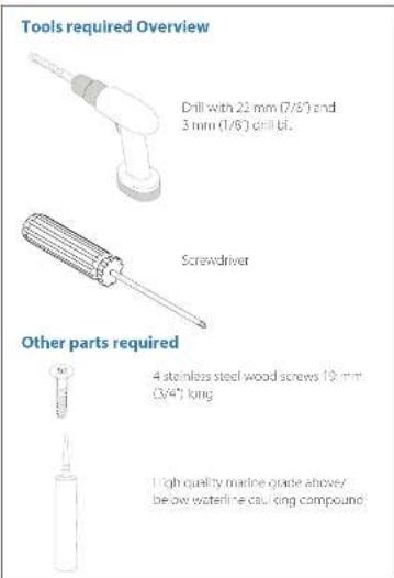

Plan the installation install the Speed Sensor
To install the speed sensor, first find a location on the boat's transam where the water flow is smoothest. Don't mount the sensor behind snakes or ribs. Those will disturb the water flow to the speed sensor. Make sure the sensor will remain in the water when the boat is on plane. Also make sure the location doesn't interfere with the boat's trailer. Typically, the sensor is mounted about one foot to the side of the transam's center line.


Once you've determined the proper location for the unit, place the sensor on the strainon with the bracket flush with the hull's bottom, using the sensor as a template, mark the hull for the screws' prior holes (1). Drill four 3 mm (1/8") holes, one in each end of the slots (2). Mount the sensor to the hull using #8 stainless steel wood screws (2). Use a high quality, marine grade above or below-waterline sealant to seal the screws. Make sure the sensors is flush with the bottom of the hull and tighter the screws.

If the base of the transom has a radius, fill the gap between the transom and the sensor with sealant. This will help ensure a smooth water flow.
If you drill a hole in the transom for the cable, make sure it is located above the waterline. After installation, be sure to seal the cable hole with the same marine grade above or below-waterline sealant used for the screws.
Connect the Speed Sensor to the network

A Paddle wheel with speed sensor
3 Processing unit
C NMEA COD CAN bus backbone
Q 12 VDC. Power supply. Connect via a switch and lamp fuse
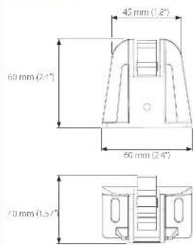
Dimensions
Specifications
Speed Range between 0 and 80 km/h.
PGNs transmitted
59392 - ISO Acknowledgment
60928 ISO Address Claim
126935 Product Information
128259 - Speed, Water Referenced
Brand : SIMRAD
Model : Speed Sensor
Category : Speed sensor