COMET - Cutting machine Cigweld - Free user manual and instructions
Find the device manual for free COMET Cigweld in PDF.


| Product Type | Oxy-fuel pipe cutting machine |
| Brand | Cigweld |
| Model | COMET |
| Pipe Diameter Range | 108-600 mm (standard chain), over 600 mm with extra chain |
| Maximum Cutting Thickness | 50 mm |
| Cutting Shapes | Square and bevel (up to 45°) |
| Drive Method | Manual (hand crank) |
| Gas Requirements | Oxygen and acetylene only |
| Standard Chain Length | 2.4 m |
| Nozzle Type | Type 41 (high-speed cutting nozzle) |
| Included Accessories | Torch, torch holder, gas distributor, twin hose 600 mm, nozzle (size 8HS), 2 large wheels, 2 spanners, tip cleaner, 6 M5 screws, operating manual |
| Maintenance Schedule | Weekly oiling of rotary sections (wheels, sprocket, worm gear, handle, bearings, chain tension wing nut, lift shafts) |
| Safety Features | Flashback arrestors recommended (not included) |
| Warranty Period | 12 months |
Frequently Asked Questions - COMET Cigweld
User questions about COMET Cigweld
0 question about this device. Answer the ones you know or ask your own.
Ask a new question about this device
Download the instructions for your Cutting machine in PDF format for free! Find your manual COMET - Cigweld and take your electronic device back in hand. On this page are published all the documents necessary for the use of your device. COMET by Cigweld.
USER MANUAL COMET Cigweld
natural_image
Mechanical device with blue and red tubing, brass fittings, and mechanical components (no visible text or symbols)WE APPRECIATE YOUR BUSINESS!
Congratulations on your new CIGWELD product. We are proud to have you as our customer and will strive to provide you with the best service and reliability in the industry. This product is backed by our extensive warranty and accredited service network. To locate your nearest distributor or service provider call 1300-654-674, or visit us on the web at www.cigweld.com.au.
This Operating Manual has been designed to instruct you on the correct use and operation of your CIGWELD product. Your satisfaction with this product and its safe operation is our ultimate concern. Therefore please take the time to read the entire manual, especially the Safety Precautions. They will help you to avoid potential hazards that may exist when working with this product.
YOU ARE IN GOOD COMPANY
The Brand of Choice for Contractors and Fabricators. CIGWELD is a Market Leading Brand of Arc and Gas Cutting & Welding Products for ESAB.
We are a mainline supplier to major gas cutting & welding industry sectors in the Asia Pacific and emerging global markets including; Manufacturing, Construction, Mining, Automotive, Engineering, Rural and DIY.
We distinguish ourselves from our competition through market leading dependable brands that have stood the test of time, technical innovation, competitive prices, excellent delivery, superior customer service and technical support, together with excellence in sales and marketing expertise.
We are committed to develop technologically advanced products to achieve a safer working environment for industry operators.
Read and understand this entire Manual and your employer's safety practices before installing, operating, or servicing this product.
While the information contained in this Manual represents the Manufacturer's best judgement, the Manufacturer assumes no liability for its use.
Instruction Manual Number 338205-01-018 for:
Comet Pipecutter
Published by:
CIGWELD Pty Ltd
CIGWELD An ESAB Brand
71 Gower Street
Preston, Victoria, Australia, 3072
www.cigweld.com.au
Copyright 2018 by
CIGWELD An ESAB Brand
All rights reserved.
A reproduction of this work, in whole or in part, without written permission of the publisher is prohibited.
The publisher does not assume and hereby disclaims any liability to any party for any loss or damage caused by any error or omission in this Manual, whether such error results from negligence, accident, or any other cause.
Publication Date: Oct 15, 2018
Record the following information for Warranty purposes:
Where Purchased:
Purchase Date:
This page intentionally left blank.
TABLE OF CONTENTS
SECTION 1:
GAS EQUIPMENT SAFETY INSTRUCTIONS AND WARNINGS ......Page 6
1.01 Personal Safety......Page 6
1.02 Cylinders – General......Page 6
1.03 Oxygen Cylinders ...... Page 7
1.04 Acetylene Cylinders Page 7
1.05 LPG Cylinders......Page 8
1.06 Regulators Page 8
1.07 Flashback Arrestors Page 9
1.08 Gas Welding Hose ...... Page 9
SECTION 2:
INTRODUCTION Page 11
2.01 Box Contents ...... Page 11
2.02 Gas Requirements ...... Page 11
SECTION 3:
INSTALLATION AND USE......Page 12
3.01 Pre-Operation Handling Precautions Page 12
3.02 Preparation for Operation ...... Page 13
3.03 Testing For Leaks before Use Page 13
3.04 After Completion of Use (Shut-down)......Page 14
3.05 Determining the Number of Chain Links Page 14
3.06 Securing Machine to Pipe Page 15
SECTION 4:
CUTTING OPERATION......Page 16
4.01 Safety Precautions Prior to Operation Page 16
4.02 Cutting and Piercing ...... Page 16
4.03 Preparation for Cutting Operation Page 17
4.04 Cutting Operation ......Page 17
SECTION 5:
MAINTENANCE AND INSPECTION Page 18
SECTION 6:
TROUBLE-SHOOTING Page 18
SECTION 7:
ASSEMBLY DIMENSIONS......Page 19
SECTION 8:
CUTTING DATA......Page 19
SECTION 9:
ACCESSORIES & SPARE PARTS Page 20
SECTION 10:
WARRANTY Page 21
SECTION 1: GAS EQUIPMENT SAFETY INSTRUCTIONS AND WARNINGS
The information shown under this note must be followed carefully to avoid injuring the operator or anyone in the operating area.
When an accident does occur with gas equipment, it's usually due to the operator having become careless through over-familiarity. Remember, the safest of equipment, if wrongly handled, can cease to be safe. For safe welding and cutting check and re-check the points in this article. Each point is there for a purpose.

1.01 Personal Safety
Be neat and clean about your work. Maintain your equipment in good condition. Wear goggles with the correct shade filter when using gas equipment. Goggles protect your eyes against sparks and injurious rays. It is essential that the goggles and filters are of a type intended for cutting work. Quite apart from safety, they help you see your work better. Wear suitable gloves, aprons, shoes and protective clothing. Watch for sparks in sleeves, cuffs and open pockets. Never use oxygen to dust clothes or work. Use a flint lighter or pilot light to light blowpipe. Never use matches. Keep flame, sparks or metal away from cylinders and tubing. When working with lead, lead bearing materials, steel coated with lead paints, cadmium-coated materials or any objects containing metals giving off toxic fumes, always use a suitable respirator.

1.02 Cylinders – General
Industrial gas cylinders are made to rigid specifications and are inspected each time they are refilled by your supplier. They are safe – if properly handled. All Government and insurance regulations relating to the storage of oxygen, acetylene and LPG cylinders should be closely observed. Keep all cylinders, empty or full, away from radiators, furnaces and other sources of heat. Also avoid contact with electrical circuits. Keep oil and grease away from cylinders. Cylinders standing in the open should be screened against direct rays of the sun. Protect cylinders valves from bumps and falling objects. Keep the valves clean, free from oil, grease and all foreign materials. Close cylinder valves when not in use, when empty, or when moving cylinders. Always remove regulators when moving cylinders. Be sure the cylinder valve is tightly closed before removing regulators. Never allow anyone to strike an arc or tap an electrode against any cylinder. Never try to fill a cylinder or mix gases in a cylinder. Never tamper with or alter cylinder numbers or markings. Never use cylinders as supports or rollers. When transporting cylinders using a crane, do not use slings- use a cylinder cradle. Never draw gas from cylinders except through properly attached pressure regulators or equipment designed for the purpose. If damaged, send the regulator to the supplier or appointed agent for repairs. If unable to make a gas-tight seal between the cylinder valve and a regulator spigot, first check whether the spigot nut is tight. If so check the regulator spigot. If the cylinder valve is damaged notify the gas supplier. Never insert washers of lead or other material between the regulator and the cylinder valve. Never use oil or grease on these connections. Use only standard cylinder keys to open cylinder valves, never extend the length of these keys under any circumstances. If valves cannot be opened by hand, do not use a hammer or wrench; notify the supplier. Open all cylinder valves slowly. Leave cylinder key in position when fuel gas cylinder valves are open.
Oxygen cylinders are steel shells of ample strength for their purpose. Besides routine inspections, they periodically undergo a searching examination, which includes a hydraulic pressure test. Always call oxygen “Oxygen” not “Air”.
Never use oxygen in pneumatic tools, in oil pre-heating burners, to start engines, to blow out pipelines or to freshen the atmosphere in confined spaces.
In short, under no circumstances use oxygen as a substitute for compressed air or other gases.

1.04 Acetylene Cylinders
Acetylene cylinders contain porous material, which is impregnated with acetone. The acetylene is dissolved under pressure in this acetone. All acetylene cylinders are fitted with fusible plugs. These are designed to vent the cylinder contents in the event of an unsafe condition arising in the cylinder due to any cause such as overheating or decomposition arising from either incorrect operating technique, faulty equipment alone, or in conjunction with excessive temperature. In the event of a safety devise functioning, always notify the supplier. The reason for the devise operating always warrants special investigation. Always call acetylene “acetylene” not Gas. Always keep acetylene cylinders upright, whether in use or in store, full or empty. Always keep acetylene cool, store them upright in a well protected, well ventilated dry location, away from highly combustible materials and oxygen cylinders. Should an acetylene valve leak around the spindle, close the valve and tighten the gland. If this fails, or if the fusible plug is leaking, remove cylinder to open air. Keep the cylinder well away from anything which could possibly set the escaping acetylene on fire. Tag the cylinder to explain the trouble. Notify suppliers at once. If acetylene, escaping from a leaking cylinder valve gland or from an improperly seated regulator spigot ignites, immediately close the cylinder valve. If this is impossible, treat from point two below. If an acetylene cylinder is heated accidentally or becomes hot through severe flashback, or other cause, action should be taken promptly in the following manner:
- Shut the cylinder valve
- Clear all personal from the area
- Cool the cylinder with a copious supply of water and notify the fire brigade
NOTE: The person directing the fire hose should be protected behind some suitable shelter. If the safety device functions and the issuing gas ignites, cool the cylinder as above, but avoid extinguishing the flames. If the escaping gas does not ignite, care must be taken to avoid an air/acetylene explosion. No source of ignition must be permitted to enter the area. Existing sources of ignition should be rendered safe. - Continue cooling the cylinder with copious quantities of water until it is quite cool. This maybe determined by removing the cooling water at intervals and watching whether the water on the cylinder fries off, or whether the cylinder remains wet.
- Notify the supplier
- In cases where the supplier's representative is unavailable or cannot reach the scene of the incident within half an hour, the cylinder may after this period be removed carefully to an open space away from buildings and any source of ignition provided it remains cool and wet.
- The cylinder valve should then be opened until the cylinder is empty. During this period a copious quantity of water should be poured on the cylinder.
- When the cylinder is empty check whether the cylinder is cool, if so, close the valve.
LPG cylinders are provided with relief valves or fusible plugs to discharge their contents and keep the cylinder pressure within safe limits should the cylinder be overheated by a fire. LPG cylinders should be used and stored upright in the open, away from combustible material. Do not store LPG cylinders with oxygen cylinders. Do not store LPG cylinders closer than 1.5 m horizontally from any opening into a building. If LPG cylinder valve leaks around the spindle, or if the relieve valve or fusible plug is leaking, remove the cylinder to open air away from buildings and sources of ignition; tag the cylinder to explain the trouble; notify the supplier as soon as possible. If LPG escapes from a leaking cylinder valve gland or from a regulator spigot ignites, immediately close the cylinder valve. If LPG escaping from a fusible plug ignites, direct a fine water spray at the cylinder and surrounding equipment. On no account should the flame be extinguished, since escaping unburned gas in a confined space may re-ignite and cause an explosion. LPG is not toxic and is odourless, but an odorant is added to give a distinctive smell. If the distinctive odour is detected an immediate check should be made for leaks. Soapy water is recommended for this purpose. As soon as the leak is located, turn off the LPG cylinder valve and tighten or repair the equipment. If LPG is leaking do not strike matches or operate any electrical appliance in the vicinity. Remove all sources of ignition and open all doors and windows. Do not attempt to relight LPG until all traces of LPG odour have disappeared. Remember, LPG is heavier than air and will remain in open containers, cellars and confined spaces for a considerable time.

1.06 Regulators
Do not work with damaged equipment. Have leaking or damaged equipment repaired by an authorized repair agent. Give your gas equipment the care you would give any other dependable tool. Do not use oil or grease on any regulator. Do not handle equipment with an oil rag, oily gloves or hands. Keep your equipment clean. Never use regulators for purposes other than that for which they were intended. Inspect connections and all seating surfaces on regulators before use. Damaged connections can cause leaking or flashbacks. Never hang a blowpipe or tubing on a regulator or cylinder valve. Crack cylinder valves before attaching regulators. Cracking means to open the valve a little, then immediately close, to blow out dust or foreign matter. Cracking should always be done gently. Never crack a fuel gas valve near other welding works, sparks or open flame. Never crack a Hydrogen cylinder as this can cause the gas to self-ignite. Never force connections. Be sure all connections are tight. Never test for leaks with a flame. Never try to connect a regulator to a cylinder containing gas other than that for which the regulator is meant. Never subject the regulator to inlet pressures greater than its rated inlet pressure, as shown on regulator body and associated literature. If a regulator shows excessive creep (pressure build-up when blowpipe valves are closed), close cylinder valve and have regulator repaired at once. Quite apart from risks, creeping regulators lead to poor work. Pressure build-up in excess of 35 kPa is to be regarded as excessive and call for immediate attention. Periodically, have pressure gauges on regulators tested for accuracy. Ensure before using that regulators have both a cylinder pressure and a delivery pressure gauge in working order. Before opening cylinder valves always fully release regulator adjusting knob (turn fully anticlockwise). A sudden pressure rise in a regulator whose adjusting knob is screwed in puts a heavy strain on the mechanism and may cause damage. Never release the regulator adjusting knob while there is pressure in the tubing. If the pressure gauge indicator fails to return to the stop when pressure is released, have the gauge checked.
Always take care to keep the regulators free of oil and grease. Oil and grease should be removed chemically by a qualified repair technician. Never use oil or grease on the regulator, cylinder or manifold connections. Do not change the inlet connection on a regulator in an attempt to use the regulator for a different gas service.
Gasguard™ safety device (where fitted to selected regulators)
Gasguard™ is a non-return valve that completely seals off the gas should the regulator break from the cylinder. In order for this to operate correctly it must be used in conjunction with the extended nut provided with the regulator. Failure to do so could result in the Gasguard feature not operating in line with its intended design function.
A flashback occurs when mixed gases within a cutting and welding blowpipe system ignite and, due to several possible reasons burn back through the system against the flow of gas. The consequences of a flashback range from sooting of the hose, to serious equipment fires and possible explosion. Low operating pressures, inadequate gas supply, damaged equipment or poorly maintained equipment substantially increase the likelihood of flashbacks occurring. Flashback arrestors correctly used virtually eliminate the possibility of a flashback causing harmful damage.
CIGWELD's market leading range of COMET flashback arrestors conform to national and international standards (AS4603, EN 730, ISO 5175 - Connection fittings to AS4267) and are manufactured under an ISO9001 accredited quality management system. This comprehensive range includes products suitable for all applications.
CIGWELD's COMET flashback arrestors have been designed with state of the art technology to provide the ultimate protection and virtually eliminate flashbacks because it is impossible to either predict or completely eliminate the potential hazard of a flashback.
Standards
Australian Standard AS 4267 - 1995 Pressure Regulators for use with Industrial Compressed Gas Cylinders recommends flashback arrestors be used in Oxy-fuel gas applications. Australian Standard AS 4289 - 1995 Oxygen and Acetylene Gas Reticulation Systems, specifies the use of flashback arrestors in Oxy-fuel applications. AS4603 is a new standard for flashback arrestors only. Make sure the flashback arrestors you use now have this labelled on them.
Testing
AS 4289-1995 states flashback arrestors shall be tested annually, this can be done by one of CIGWELD's extensive network of accredited service agents. Flashback arrestors should also be tested if they have been subjected to backfiring and flashbacks. Contact your nearest distributor for advice on the correct type of flashback arrestors that should be fitted to cater for your application(s)
NOTE: In Western Australia the Occupational Safety and Health Regulations 1996 (Reference 3.98) requires flashback arrestors to be fitted at the outlet side of each regulator or gas discharge of a manifolded cylinder pack; and at the blowpipe. This is also supported by Australian Standard AS 4839 that recommends the use of flashback arrestors and list 3 options in order of preference for their fitment. CIGWELD recommends fitting flashback arrestors to both the regulator outlet and blowpipe inlet connections, providing the ultimate protection for the operator.

1.08 Gas Welding Hose
Gas welding hose is an essential yet vulnerable link in the system that provides flexibility and freedom of movement for the operator. Quality hoses, such as CIGWELD's COMET hoses, which comply to Australian Standards, are designed and manufactured to safely withstand high pressures, crushing, contact with certain chemical compounds, contaminants, ignition as well as burning, and environmental abuse. Hoses however are the weakest point of the Oxy-fuel system and provide potentially the greatest source of gas leaks. As a result, only quality hose which complies to AS 1335 - 1995 should be used (in conjunction with compatible hose fittings), so as to maximise the safety and durability of this part of the system. Welding hoses which comply to Australian Standards are colour coded to the gas for which they are to be used (Red-Acetylene, Blue-Oxygen, Orange-LPG, and Black-Inert).
Hose assemblies should be checked regularly for gas leaks, signs of external damage, perishing and for fit up to the hose fittings. If required the necessary repairs or replacement should be made immediately. For large flow applications and long lengths of hose 10mm or 13mm bore hose should be used.
Pressure Drop
Pressure drop simply means that for gas to flow through the hose, for a given pressure at the beginning of the hose (eg. at the regulator), the pressure at the other end of the hose (e.g. at the blowpipe) will be less. For a given flow and length of hose, the pressure drop in a small bore hose, will be greater than in a larger bore hose. This means, that wherever possible, hose lengths should be kept to a minimum and hose bore diameters kept to a maximum. Doing so will reduce the amount of pressure drop, therefore minimising the chance of affecting the performance or stability of the process flame. Minimising hose lengths also provides greater protection to the hose against damage. Excessive pressure drops can starve a tip or nozzle of an adequate gas supply, which in turn can lead to reduced flame intensity, backfiring or flashbacks.
Hose Fittings
The design of the hose connection must provide high mechanical strength and resistance to leakage under a wide range of conditions. Further, non-interchangeability of hose fittings is maintained by using a right hand (RH) thread for Oxygen and a left hand (LH) thread for fuel. CIGWELD's COMET hose fittings fulfil all of these important requirements. Dimensions for hose fitting connector nuts and nipples are given in AS 4267.
SECTION 2: INTRODUCTION
2.01 BOX CONTENTS
The Comet Pipecutter Box comes complete with the components listed below. Ensure when unpacking the box that all components are present.
1 x Comet Pipecutter
1 x Operating Manual
1 x Torch Holder
1 x Torch
1 x Gas Distributor
1 x Torch Holder Bracket
1 x Twin Hose 600 mm
1 x Nozzle Type 41 Size 8HS
1 x 2.4 metre Chain
2 x Large Wheel
2 x Spanner
1 x Tip Cleaner
6 x M5 Screws
2.02 GAS REQUIREMENTS
This Comet Pipecutter is suitable for use with oxygen/acetylene gases only. Cylinders of these gases are available in various sizes dependent upon your usage requirements. Your local gas distributor will be able to assist in obtaining the suitable grades of gases and cylinder sizes required for this Pipecutter.
3.01 PRE-OPERATION HANDLING PRECAUTIONS
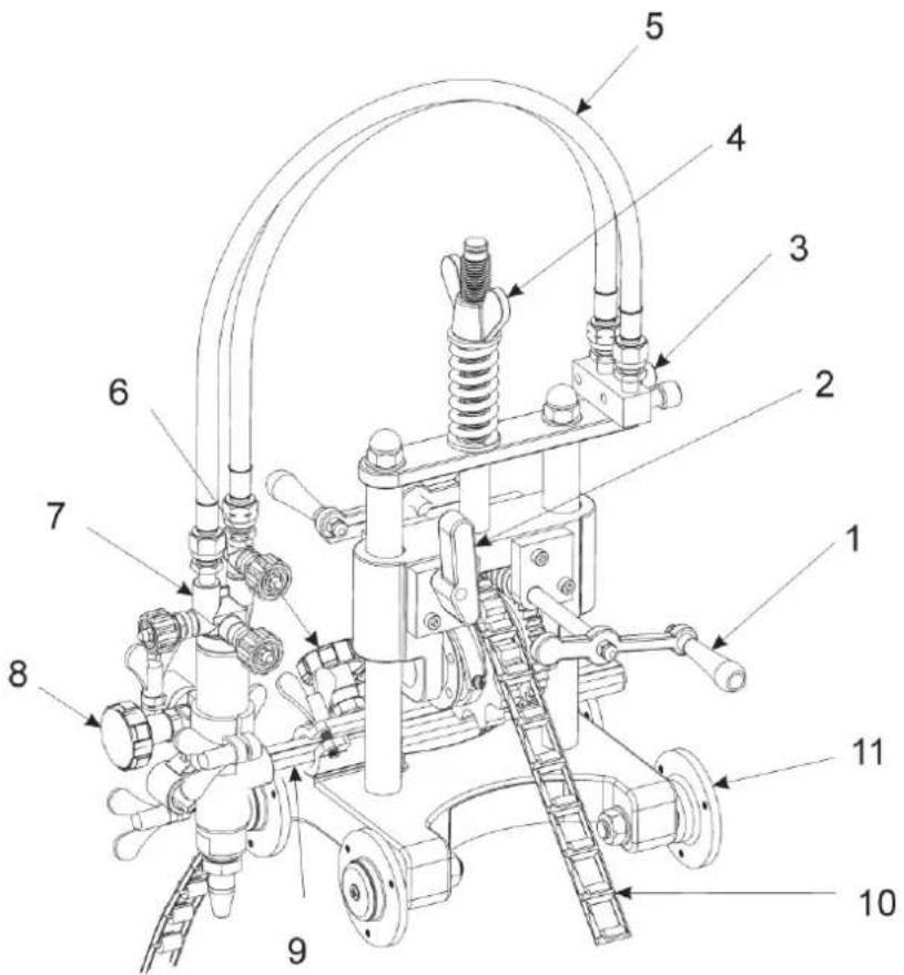
- Handle
Drives the machine.
- Clutch Lever
Engages/dis-engages the handle drive worm from the chain sprocket.
- Gas Distributor
Oxygen and acetylene gas inlets.
- Wing Nut
Controls the chain tension.
- Gas Hoses
Oxygen - blue, acetylene - red.
- Torch Side Handle
Moves the torch left and right.
-
Torch
-
Up/Down Handle
-
Lateral Bar
-
Chain
Engages with sprocket to drive
- Wheel
Specifications
| Pipe diameter | 108-600 mm by standard 2.4 m chain. Over 600 mm by extra chain addition. |
| Cutting thickness | Up to 50 mm |
| Cutting shape | Square and bevel (up to 45°) |
| Drive method | Manual |
| Nozzle | Type 41 |
- Carefully take the machine out of the case.
- Carefully check that the torch holder, gas distributor, torch etc. are in correct positions.
- Attach the gas supply hoses to the gas distributor.
Oxygen hose – Blue
Acetylene hose - Red
— Check that the hoses are connected properly and there is no gas leakage.
- Refer to the Cutting Data (see page 18) to select the right cutting nozzle for the thickness of steel pipe to be cut.
- Always make sure the cutting tip is fastened tightly to the torch. Be careful when handling the cutting tip not to damage the tapered section.
3.03 TESTING FOR LEAKS BEFORE USE
After assembly and before use, it is recommended that the following procedure be adopted to check for leaks.
- Before opening the cylinder valve, turn the Regulator adjusting knob fully anti-clockwise until there is no pressure on the internal adjusting spring and the knob turns freely.
- Ensure all valves on downstream connected equipment are closed.
- Stand to the side of the cylinder opposite the Regulator adjusting knob before opening the cylinder valve. Keep the cylinder valve between you and the Regulator.
- Open the cylinder valve slowly - if opened quickly, a sudden pressure surge may damage internal Regulator parts. Set the Regulator to show approximately 100 kPa on the delivery gauge, by turning the adjusting control knob clockwise.
- Close the cylinder valve.
- Turn the adjusting knob anti-clockwise one turn:
a) If the high pressure (cylinder contents) gauge reading drops, there is a leak in the cylinder valve, inlet fitting, or high pressure gauge.
b) If the low pressure (delivery) gauge drops, there is a leak in the downstream equipment, hose, hose fitting, outlet fitting, or low pressure gauge. Check for leaks using a suitable leak detection solution.
c) If the high pressure gauge drops and the low pressure gauge increases at the same time, there is a leak in the internal Regulator seat.
d) If the Regulator requires service or repair, refer to Section 5.
- If there are no leaks found, then the system is ready for use.
- Repeat test for the second gas system (where applicable)
IMPORTANT:
This test should be done quickly, and it is important that there are no sources of ignition present during this process, as a certain amount gas will be released to the atmosphere. If no leaks are detected, the system is ready for use. In an Oxy/Fuel system, particular care needs to be taken to ensure that gasses are not mixed, as this may lead to flashback upon lighting up. If leaks are detected in the system, then the joint should be re-tightened and re-tested, or the leaking item replaced. If any leaks are detected from a torch, it should be returned to the distributor from which it was purchased.
3.04 AFTER COMPLETION OF USE (SHUT-DOWN)
- Close the cylinder valve whenever the Regulator is not in use. To shut down for extended periods (more than 30 minutes):
a) Close the cylinder or upstream valve tightly.
b) Open the downstream equipment valves to release all gas pressure from the system. Bleed gas into a well ventilated area and away from any ignition source.
c) After gas is drained completely, turn the Regulator adjusting knob anti-clockwise until there is no pressure on the internal adjusting spring and the knob turns freely.
d) Close the downstream equipment valve.
3.05 DETERMINING THE NUMBER OF CHAIN LINKS
The relationship between the pipe outside diameter and the number of chain links is as follows;
$$ Y = D (\text { centimetre }) + 1 2 $$
Y = the number of chain links.
D = pipe outside diameter. (Round off the value on mm to the next value in cm)
Example: Pipe outside diameter = 258mm. (258mm = 25.8cm = 26)
$$ Y = D + 1 2 $$
$$ Y = 2 6 + 1 2 $$
$$ Y = 3 8 $$
Therefore, 38 links are required to cut 258mm diameter pipe.
3.06 SECURING MACHINE TO PIPE
- Calculate the necessary number of links.
- Place the main unit on the pipe to be cut and turn the chain tension wing nut anti-clockwise to lower the slide bracket.
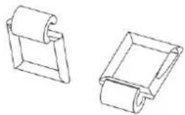
- Engage the chain with the sprocket in the correct orientation as shown below.
- Turn the chain tension wing nut clockwise to fix the machine to the pipe, exercising care not to over tighten the spring.
- Hold the machine and dis-engage the clutch. Push the machine to the right and left within a range of 120 degrees two or three times, tensioning the chain gradually. After setting, move the machine through the full circumference of the pipe to ensure the hose length is sufficient and the nozzle returns to its original position. Re-engage clutch.
A
natural_image
Two 3D mechanical component diagrams showing folded and rectangular parts (no text or symbols)B
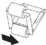
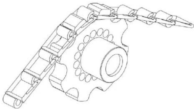
natural_image
Technical line drawing of a mechanical gear assembly with no visible text or symbolsC
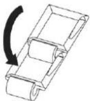
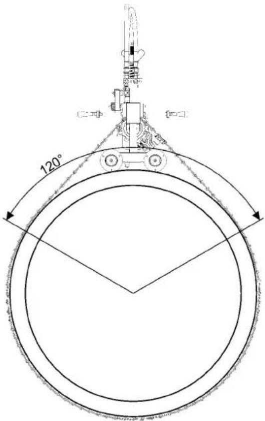
SECTION 4: CUTTING OPERATION
Strictly observe safety rules, precautions and instructions to ensure safety during the gas cutting operation.
4.01 SAFETY PRECAUTIONS PRIOR TO OPERATION
- Refer to the Cutting Data (see page 18) to select the right cutting nozzle for the thickness of steel pipe to be cut.
- For a heavily rusted surface or a bevel cutting angle of more than 20 degrees, select the nozzle one size bigger than the one shown in the cutting data.
Ignition and flame adjustment
Adjust the gas pressures according to the cutting data. The data shows the pressure when all gas valves are fully open. Readjust the pressure after ignition.
Flame adjustment
- Open the fuel gas valve 14 to 12 a turn.
- Light the torch using a flint or piezo lighter. DO NOT USE MATCHES OR CIGARETTE LIGHTERS.
- Adjust the fuel valve until the flame just ceases to smoke.
- Open the preheat oxygen valve until a neutral flame is obtained. A NEUTRAL flame is when the preheat flames on the nozzle become sharp, well defined white cones with a slight acetylene feather.
- Open the cutting oxygen valve fully and re-adjust the oxygen valve to again obtain a neutral flame.
A disorderly flow of cutting oxygen will adversely affect the quality of the cutting surface. In such a case, the cutting oxygen hole in the nozzle has to be cleaned.
-
Close both the acetylene and the preheat oxygen valves before cleaning the cutting oxygen hole.
-
Clean the nozzle with a suitable nozzle cleaner while the cutting oxygen is flowing.
A neutral flame ensures a good quality cut surface. (Oxidising flames may be used for bevel cutting). An oxidising flame shortens the cutting oxygen flow causing slag deposition or melting of the upper edge of the cut surface. An excessively high cutting oxygen pressure will cause the same effect.
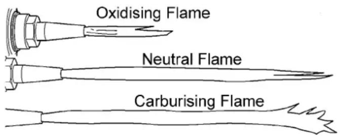
4.02 CUTTING AND PIERCING
Methods
- Cut in from the end of pipe.
- Pierce pipe before cutting.
- Drill a hole before cutting.
Piercing Method
- Ignite and adjust the flame.
- Thoroughly preheat the cut-in point until it is white hot.
- Open the oxygen cutting valve to pierce the pipe. The nozzle should be approximately 15-20mm from the pipe to prevent slag from splashing onto the nozzle and adhering there, which will shorten the life of the nozzle.
- Align the nozzle with the cutting start point, ignite, and then adjust the flame.
- Sufficiently preheat the cutting start point.
- After heating, open cutting oxygen valve and turn the handle simultaneously to begin cutting.
- Carefully check the cutting condition and turn the handle to set the optimum cutting speed. For the correct cutting speed refer to cutting data (see page 18).
- Extinguish the flame after cutting as follows:
a. Stop turning the handle.
b. Close the cutting oxygen valve.
c. Close the acetylene valve.
d. Close the oxygen preheat valve.
- Align the nozzle with the cutting starting point.
- Ignite the nozzle and sufficiently preheat the pipe.
- Open cutting oxygen valve and turn the handle simultaneously to begin cutting. During cutting, hold the chain tension wing nut with right or left hand. When the machine moves down, support the machine from the bottom and when the machine moves up lift the machine.
- While observing the cutting condition and turn the handle to set the optimum cutting speed.
- When cutting has finished, stop the handle and close the cutting oxygen valve, close the acetylene gas valve, then the preheat oxygen valve, in that order.
SECTION 5: MAINTENANCE AND INSPECTION
5.1 Weekly Inspection
Oil the rotary section of the machine (wheel, sprocket, worm gear, worm handle, handle and worm bearing), as well as the chain tension wing nut, lift shafts and sliding sections.
SECTION 6: TROUBLE-SHOOTING
Backfire and Flashback
The most basic problems involve backfire and flashback. While the two terms are often confused, strictly speaking backfire is when the flame ignites momentarily inside the torch and then goes out, or goes out and re-lights (punching backfire), whereas flashback refers to the flame burning continuously inside the torch (sustained flashback).
1. Backfire – causes
a) Incorrectly adjusted gas pressures.
b) Overheated nozzle.
c) Slag sticking to nozzle.
d) Tapered seat of nozzle or torch are damaged.
Should backfire occur, find the cause and take appropriate action before using the machine again.
2. Sustained Flashback
If the flame disappears back into the torch and burns there (making a soft, hissing sound), shut the valves off in the following order immediately.
Preheat Oxygen
Fuel Gas —Cutting→Oxygen

As with backfire, find the cause and take appropriate action before using the machine again.
| Possible cause | Procedure | Remedy | |
| 1 | Machine does not run | Chain tension too tight. | Adjust |
| Worn worm gear. | Repair. | ||
| Wheel does not rotate. | Lubricate. | ||
| 2 | Rough cutting surface | Damaged cutting nozzle. | Replace. |
| Unsuitable gas pressures and cutting speed. | Readjust. |
SECTION 7: ASSEMBLY DIMENSIONS
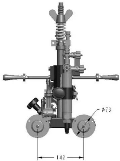
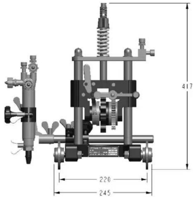
SECTION 8: CUTTING DATA
Type 41 Oxy / Acetylene
| Part Number | Size | Plate Thickness | Fuel Gas Flow l/min @ 100 kPa | Total Oxygen Flow & Pressure l/min @ kPa | Cutting Speed mm/min ^ |
| 306069 | 6HS | 6-8 | 6.0 | 31 (650) | 700 |
| 306070 | 8HS | 8-20 | 6.0 | 50 (650) | 700-550 |
| 306071 | 12HS | 25-75 | 10.0 | 107 (650) | 500-300 |
| 306072 | 15HS | 75-150 | 12.0 | 158 (650) | 300-200 |
| 306073 | 20HS | 150-250 | 13.0 | 250 (650) | 200-100 |
| 306074 | 24HS | 250-300 | 18.0 | 320 (650) | 90 |
NOTE: Preheat oxygen pressure for all hi-speed nozzles = 200 kPa
Type 44 Oxy / LPG or Natural Gas
| Part Number | Size | Plate Thickness | Fuel Gas Flow l/min @ 100 kPa | Total Oxygen Flow & Pressure l/min @ kPa | Cutting Speed mm/min ^ |
| 306018 | 6HS | 6-8 | 5.0 | 45 (650) | 550 |
| 306019 | 8HS | 8-20 | 5.0 | 64 (650) | 550-500 |
| 306021 | 12HS | 25-75 | 6.5 | 122 (650) | 500-300 |
| 306022 | 15HS | 75-150 | 7.0 | 173 (650) | 300-200 |
| 306023 | 20HS | 150-250 | 8.0 | 267 (650) | 200-100 |
| 306024 | 24HS | 250-300 | 12.0 | 350 (650) | 90 |
NOTE: Preheat oxygen pressure for all hi-speed nozzles = 200 kPa
SECTION 9: ACCESSORIES & SPARE PARTS
| Part Number | Description |
| 338544 | Chain 2.4m long |
| 338547 | Torch (single) |
| 338548 | Twin hose assembly (oxygen/acetylene) |
| 338551 | Gas torch holder bracket |
| 338552 | Gas torch holder |
| 338553 | Large Wheels x 2 |
| 338556 | Torch nozzle nut |
| 338557 | M5 Screws x 6 |
| 338558 | Gas torch to suit 3 seat nozzles |
SECTION 10: WARRANTY
LIMITED WARRANTY: CIGWELD Pty Ltd, An ESAB Brand, hereafter, "CIGWELD" warrants to customers of its authorized distributors hereafter "Purchaser" that its products will be free of defects in workmanship or material. Should any failure to conform to this warranty appear within the time period applicable to the CIGWELD products as stated below, CIGWELD shall, upon notification thereof and substantiation that the product has been stored, installed, operated, and maintained in accordance with CIGWELD's specifications, instructions, recommendations and recognized standard industry practice, and not subject to misuse, repair, neglect, alteration, or accident, correct such defects by suitable repair or replacement, at CIGWELD's sole option, of any components or parts of the product determined by CIGWELD to be defective.
CIGWELD MAKES NO OTHER WARRANTY, EXPRESS OR IMPLIED. THIS WARRANTY IS EXCLUSIVE AND IN LIEU OF ALL OTHERS, INCLUDING, BUT NOT LIMITED TO ANY WARRANTY OF MERCHANTABILITY OR FITNESS FOR ANY PARTICULAR PURPOSE.
LIMITATION OF LIABILITY: CIGWELD SHALL NOT UNDER ANY CIRCUMSTANCES BE LIABLE FOR SPECIAL, INDIRECT OR CONSEQUENTIAL DAMAGES, SUCH AS, BUT NOT LIMITED TO, LOST PROFITS AND BUSINESS INTERRUPTION. The remedies of the Purchaser set forth herein are exclusive and the liability of CIGWELD with respect to any contract, or anything done in connection therewith such as the performance or breach thereof, or from the manufacture, sale, delivery, resale, or use of any goods covered by or furnished by CIGWELD whether arising out of contract, negligence, strict tort, or under any warranty, or otherwise, shall not, except as expressly provided herein, exceed the price of the goods upon which such liability is based. No employee, agent, or representative of CIGWELD is authorized to change this warranty in any way or grant any other warranty.
PURCHASER'S RIGHTS UNDER THIS WARRANTY ARE VOID IF REPLACEMENT PARTS OR ACCESSORIES ARE USED WHICH IN CIGWELD'S SOLE JUDGEMENT MAY IMPAIR THE SAFETY OR PERFORMANCE OF ANY CIGWELD PRODUCT. PURCHASER'S RIGHTS UNDER THIS WARRANTY ARE VOID IF THE PRODUCT IS SOLD TO PURCHASER BY NON-AUTHORIZED PERSONS.
The warranty is effective for the time stated below beginning on the date that the authorized distributor delivers the products to the Purchaser. Notwithstanding the foregoing, in no event shall the warranty period extend more than the time stated plus one year from the date CIGWELD delivered the product to the authorized distributor.
Any claim under this warranty must be made within the warranty period which commences on the date of purchase of the product. To make a claim under the warranty, take the product (with proof of purchase from a Cigweld Accredited Seller) to the store where you purchased the product or contact Cigweld Customer Care 1300 654 674 for advice on your nearest Service Provider. CIGWELD reserves the right to request documented evidence of date of purchase. CIGWELD or our Accredited Distributor must be notified in writing of its claim within seven (7) days of becoming aware of the basis thereof, and at its own expense returning the goods which are the subject of the claim to CIGWELD or nominated Accredited Distributor/Accredited Service Provider.
This warranty is given.
Cigweld Pty Ltd
A.B.N. 56007226815
71 Gower Street, Preston
Victoria, Australia, 3072
Phone: 1300 654 674
Email: enquiries@cigweld.com.au
Website: www.cigweld.com.au
This warranty is provided in addition to other rights and remedies you have under law: Our goods come with guarantees which cannot be excluded under the Australian Consumer Law. You are entitled to replacement or refund for a major failure and to compensation for other reasonably foreseeable loss or damage. You are also entitled to have the goods repaired or replaced if the goods fail to be of acceptable quality and the failure does not amount to a major failure.
Warranty period: 12 months.
Notes.
This page left intentionally blank.
CIGWELD Pty Ltd
CIGWELD An ESAB Brand
71 Gower Street, Preston VIC 3072 Australia
Customer Care
Tel: 1300 654 674 | Fax: 03 9474 7391
Email: enquiries@cigweld.com.au
International Enquiries
Tel: +61 3 9474 7508 | Fax: +61 3 9474 7488
Malaysia
Lot 151, Jalan Industri 3/5A
Rawang Integrated Industrial Park,
Jin Batu Arang
48000 Rawang Selangor Darul Ehsan
West Malaysia
Tel: 60 3 6092 2988 | Fax: 60 3 6092 1085
Indonesia
JL Akasia II Blok A-05 No. 10A
Delta Silicon - Lippo Cikarang
Bekasi, 17550
Indonesia
Toll Free: 0 800 1842 867
Tel: +62 21 8990 6095 | Fax: +62 21 8990 6096
- WE APPRECIATE YOUR BUSINESS!
- YOU ARE IN GOOD COMPANY
- TABLE OF CONTENTS
- SECTION 1:
- GAS EQUIPMENT SAFETY INSTRUCTIONS AND WARNINGS ......Page 6
- SECTION 2:
- INTRODUCTION Page 11
- SECTION 3:
- INSTALLATION AND USE......Page 12
- SECTION 4:
- CUTTING OPERATION......Page 16
- SECTION 5:
- MAINTENANCE AND INSPECTION Page 18
- SECTION 6:
- TROUBLE-SHOOTING Page 18
- SECTION 7:
- ASSEMBLY DIMENSIONS......Page 19
- SECTION 8:
- CUTTING DATA......Page 19
- SECTION 9:
- ACCESSORIES & SPARE PARTS Page 20
- SECTION 10:
- WARRANTY Page 21
- SECTION 1: GAS EQUIPMENT SAFETY INSTRUCTIONS AND WARNINGS
- Personal Safety
- Cylinders – General
- Acetylene Cylinders
- Regulators
- Gasguard™ safety device (where fitted to selected regulators)
- Standards
- Testing
- Gas Welding Hose
- Pressure Drop
- Hose Fittings
- SECTION 2: INTRODUCTION
- BOX CONTENTS
- GAS REQUIREMENTS
- PRE-OPERATION HANDLING PRECAUTIONS
- Specifications
- TESTING FOR LEAKS BEFORE USE
- IMPORTANT:
- AFTER COMPLETION OF USE (SHUT-DOWN)
- DETERMINING THE NUMBER OF CHAIN LINKS
- SECURING MACHINE TO PIPE
- SECTION 4: CUTTING OPERATION
- SAFETY PRECAUTIONS PRIOR TO OPERATION
- Ignition and flame adjustment
- Flame adjustment
- CUTTING AND PIERCING
- Methods
- Piercing Method
- SECTION 5: MAINTENANCE AND INSPECTION
- Weekly Inspection
- SECTION 6: TROUBLE-SHOOTING
- Backfire and Flashback
- Backfire – causes
- Sustained Flashback
- SECTION 8: CUTTING DATA
- SECTION 10: WARRANTY
Brand : Cigweld
Model : COMET
Category : Cutting machine