
RP3.2-TY11 - Car radio PAC - Free user manual and instructions
Find the device manual for free RP3.2-TY11 PAC in PDF.


User questions about RP3.2-TY11 PAC
0 question about this device. Answer the ones you know or ask your own.
Ask a new question about this device
Download the instructions for your Car radio in PDF format for free! Find your manual RP3.2-TY11 - PAC and take your electronic device back in hand. On this page are published all the documents necessary for the use of your device. RP3.2-TY11 by PAC.
USER MANUAL RP3.2-TY11 PAC
Introduction & Features
The RP3.2-TY11 allows for replacement of the factory radio in select Toyota / Lexus / Scion vehicles and will retain the factory amplifier. The harness also provides connections for: vehicle speed signal (VSS), reverse trigger, parking brake, and plug-n-play connection (SWI-DIRECT) for the addition of a steering wheel control interface (SWI-RC or SWI-CP2).
Important Notes
- These instructions only apply to R.2.1.1.4 or later revisions of the product. The revision info can be found on a small white sticker on the interface and packaging.
- The VSS, Reverse, and Parking Brake wires will only provide signals if the vehicle's harness is equipped with these wires.
- Adjustment of the vehicle settings through the original radio's vehicle settings menu will be disabled after installation of your new radio. It is advised to make sure all settings are as you desire prior to removal of the original radio.
- Does not retain the ability to fade through the aftermarket radio. The fade setting is only controlled by a dial on the interface.
- Does not retain Rear Seat Entertainment.
- The CAM-TY11 or CAM-TY12 must be purchased in order to retain the factory reverse camera. Please refer to www.pac-audio.com to see which harness you will need. If the required harness is not available, it is possible to hardwire the reverse camera using the information provided in Appendix A on Page 2.
Module Layout

Vehicle Connectors
Vehicle Connector 1

Vehicle Connector 2 Vehicle

Connector 3

Vehicle Connector 4
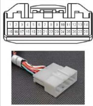
The RP3.2-TY11 requires connections of 2 of the 4 vehicle connectors. The additional connectors will remain unused on the harness. Any additional radio harnesses in the vehicle that do not plug into one of the vehicle connectors shown above, will not be used. Below you will find the typical combinations needed for most vehicles.
Combination 1
Typical 2004 to 2013
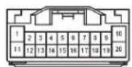

Vehicle Connector 1 Vehicle Connector 3
Combination 2
Typical 2014 to 2017

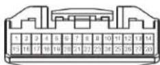
Vehicle Connector 2 Vehicle Connector 4
Installation Steps
- Wire the aftermarket radio harness per the tables to the right and the information below. If the aftermarket radio does not require connections for Vehicle Speed Sense, Parking Brake, or Reverse Signal, proceed to step "2".
a. Navigation Outputs: Plug the 28 pin connector (Vehicle Connector 4) from the RP3.2-TY11 into the vehicle harness. Find the Pink (pin 17), Light Green (pin 15) and Purple / White (pin 2) wires in the RP4.2-TY11 harness and check for wires populating these positions on the factory side of the connector. If the wires are present, you can use the analog navigation outputs coming from the Vehicle Connector in the PAC harness.
-
Connect the RP3.2 module to the 4-pin interface connector.
-
Wire the Red, Black, Yellow, Orange / White, Blue / White and the White and Gray speaker wires to the aftermarket radio and plug the interface into the vehicle.
-
Turn the ignition on and set the gain on the side of the interface to the desired level. See "Testing & Verification" section below for further details on how to set the gain.
-
If you wish to permanently fade the sound more to the front or rear, adjust the fader on the side of the interface to the desired setting. Clockwise fades to the front, counter-clockwise fades to the rear.
-
Follow the steps in the next section if you wish to add an optional SWC retention interface.
Labeled "Connect to Aftermarket Radio"
| Yellow Battery | 12v+ |
| Red Accessory | 12v+ |
| Black Ground | |
| Orange / White Illumination | |
| Blue / White | Remote Input |
| White | Front L + input |
| White / Black | Front L - input |
| Grey | Front R + input |
| Grey / Black Front R - input | |
| White / Red RCA | Factory Auxiliary Audio |
Labeled "Analog Navigation Outputs"
| *Violet / White Reverse Signal | |
| *Green Parking Brake Signal | |
| *Pink Vehicle Speed Signal |
SWI-DIRECT Steering Wheel Control Output Connector
- The RP3.2 provides a SWC output connector labeled "Connect to PAC Steering Wheel Control Interface" (Fig. A) attached to the harness. For ease of installation, all necessary connections have been made for you. Fig. A
- You can use either an SWI-RC or an SWI-CP2 (sold separately).
a. When using an SWI-RC, the loop on the output connector should remain intact. Please refer to SWI-RC instructions for radio switch setting, version assignment, and exact button programming sequence.
b. When using an SWI-CP2, use the DIP switch settings provided for the RP3.2-TY11 in the Control PRO application. The steering wheel controls will be preconfigured for the vehicle and radio but can be customized using the Control PRO application. The loop on the output connector should remain intact.
Fig. A

Testing & Verification
-
The LED and radio will turn off when the ignition is turned off.
-
Turn the ignition on. The LED on the interface will turn on and the 12v+ accessory wire will turn on.
-
Turn on the radio and check volume and balance (fader can only be set by using the dial on the side of the RP3.2 interface).
-
If the overall volume is too low, use the gain adjustment on the side of the RP3.2 interface to set the gain of the factory JBL amplifier. The best way to do this is to turn the volume on the radio to 3/4 volume, then turn the gain adjustment on the RP3.2 clockwise until some distortion is heard, then counter-clockwise a little.
Product Updates (Firmware)
The RP3.2-TY11 can be updated with new firmware as it becomes available using the RadioPRO app. Please visit www.pac-audio.com/firmware for available updates.
Appendix A (Reverse Camera Retention)
Connectors Viewed From Pin Side

| Function | Pin | Wire Color |
| Camera Power 6V + | 7 | Black |
| Vidco + | 8 | Red |
| Camera Ground | 15 | Shield |
| Video - | 16 | White |

| Function | Pin | Wire Color |
| Camera Power 6V + | 11 | Red |
| Video + | 12 | White |
| Camera Ground | 23 | Shield |
| Video - | 24 | Black |


Brand : PAC
Model : RP3.2-TY11
Category : Car radio