
VRFPR-66C - Interface de caméra automobile CRUX - Free user manual and instructions
Find the device manual for free VRFPR-66C CRUX in PDF.


| Product Type | Video Interface Module for Porsche vehicles |
| Brand | CRUX |
| Model | VRFPR-66C |
| Compatibility | Porsche Boxster, Cayenne, Cayman, 911 (2017-up) with PCM 4.0 |
| Main Functions | Adds front and backup camera inputs; extra video input; Picture-in-picture; Interactive parking guide lines with calibration; OSD settings; Two trigger outputs |
| Power Supply | 12V DC (vehicle battery) |
| Inputs | Reverse camera (R-CAM), front camera (Front Cam), video input (AV sources) |
| Outputs | LVDS to head unit; +12V trigger outputs: Pink (Power Out 1, max 1A), Green (Power Out 2, max 1A) |
| DIP Switches | 3 DIP switches for monitor size configuration (e.g., 7" ON/ON/OFF for Porsche) |
| OSD Menu | On-screen display for camera, trigger, lane lines, picture, and system settings |
| Interactive Lane Lines | Activatable via OSD; adjustable height and width |
| Picture-in-Picture | Combines rear/front cameras with factory parking sensor graphics |
| Installation | Behind radio, connects to Quadlock and LVDS connectors; includes harness and video harness |
| Components Included | VRFPR-66C module, main harness, video harness, LVDS cables |
| Dimensions | Approx. 100 x 60 x 25 mm (estimated typical module size) |
| Weight | Approx. 150 g (estimated) |
| Maintenance | Keep connections secure; avoid moisture; clean with dry cloth if needed |
| Safety | Ensure proper wiring, tape connections to avoid short circuits; use correct DIP switch settings |
| Spare Parts / Repairability | Module is integral; no user-serviceable parts; contact CRUX for repair |
| General Information | Requires factory AUX input for AV source audio; supports up to 4 cameras (rear, front, left/right side) |
Frequently Asked Questions - VRFPR-66C CRUX
User questions about VRFPR-66C CRUX
0 question about this device. Answer the ones you know or ask your own.
Ask a new question about this device
Download the instructions for your Interface de caméra automobile in PDF format for free! Find your manual VRFPR-66C - CRUX and take your electronic device back in hand. On this page are published all the documents necessary for the use of your device. VRFPR-66C by CRUX.
USER MANUAL VRFPR-66C CRUX
- Adds front and back up camera inputs plus an extra video input*.
- Uses the steering wheel control buttons or radio buttons to toggle between the inputs.
- Picture-in-picture mode combining after-market rear-view and front camera picture(s) with factory parking sensor graphics.
- Interactive parking guide lines with calibration function.
- Simultaneous use of picture-in-picture factory parking sensor graphics and interactive lane lines
- Built-in on-screen display and setup.
- 2 trigger outputs (+12V max. 1A), separately adjustable switching events (CAN, ACC, camera, reverse gear)
*Factory Audio Aux Input is required if video input will be used for AV sources.
PARTS INCLUDED:
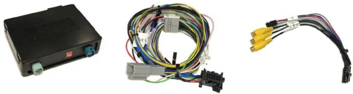
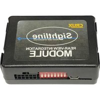
VRFPR-66C Module VRFPR-66C Harness Video Harness

natural_image
Coiled black cable with connector and terminal connector (no visible text or symbols)natural_image
Coiled black cable with two purple connectors and a small green connector (no text or symbols visible)INSTALLATION DIAGRAM:
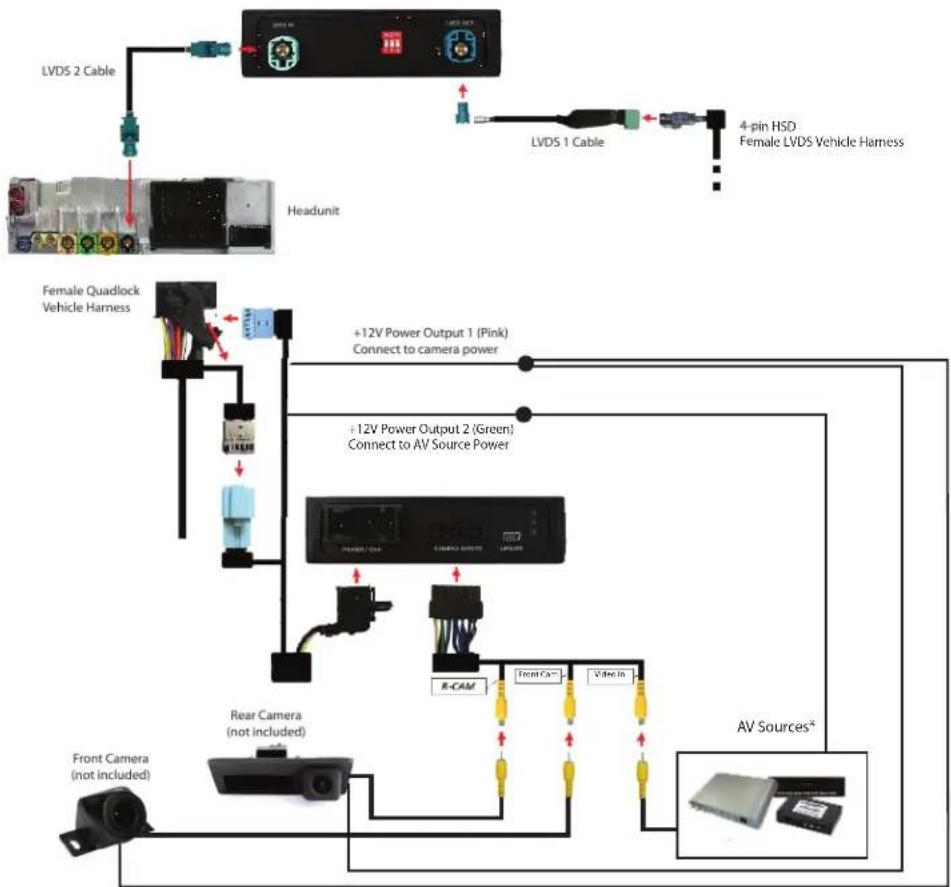
flowchart
graph TD
    A["Headunit"] --> B["LVDS 2 Cable"]
    B --> C["LVDS 1 Cable"]
    C --> D["4-pin HSD Female LVDS Vehicle Harness"]
    E["Female Quadlock Vehicle Harness"] --> F["+12V Power Output 1 (Pink) Connect to camera power"]
    E --> G["+12V Power Output 2 (Green) Connect to AV Source Power"]
    H["AV Sources*"] --> I["Rear Camera (not included)"]
    H --> J["Front Camera (not included)"]
    I --> K["R-CAM"]
    J --> L["Front Cam"]
    J --> M["Video In"]
DIP SWITCH SETTINGS:
| VEHICLE MONITOR SIZE DIP 1 DIP 2 DIP 3 | _ | _ | _ | ||
| Porsche Cayenne/Boxster | 7" ON ON OFF | ||||
INSTALLATION INSTRUCTIONS:
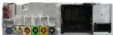
natural_image
Interior view of a computer setup with multiple labeled components (no visible text or symbols)- Installation is done behind the radio.

natural_image
Close-up of a hand holding a car interior with colorful wires and accessories (no visible text or symbols). Remove the radio to gain access to the connectors.
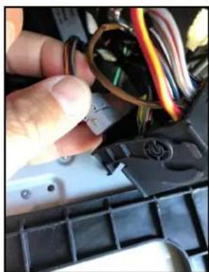
natural_image
Close-up of hands installing or adjusting a component with wires and connectors (no visible text or symbols)- Unplug the Gray connector from the Quadlock connector.

natural_image
Close-up of a hand holding a gray electrical connector with wires and cables (no visible text or symbols)- Plug in the Gray connector to the mate on the VRFPR-66C harness.

natural_image
Close-up of a car's electrical panel with visible wiring and components (no readable text or symbols)- Locate the Pink LVDS connector and unplug this.

natural_image
Close-up of a car engine bay with a connector and battery pack (no visible text or symbols)- Plug the Pink LVDS cable to the LVDS 1 cable. Plug the other end of the LVDS 1 cable to the module LVDS OUT.

natural_image
Close-up of various colored connectors and cables on a mechanical base (no visible text or symbols)- Plug one end of the LVDS 2 cable to the Pink LVDS port on the media player. Plug the other end of the LVDS 2 cable to the module LVDS IN.

natural_image
Close-up of a hand holding a car electrical connector with wires and wiring (no visible text or symbols)- Tap the Red and Black wires of the VRFPR-66C harness to power & ground: Red to RED/YELLOW Black to BROWN

natural_image
Close-up of electrical wiring and components inside a vehicle (no visible text or symbols)-
Tape the connections well to avoid short circuits.
-
Install the camera that will be used in the install. Run the camera cables towards the radio. The RCAs and camera power wires will plug into the VRFPR-66C harness.
Video Inputs
Reverse Camera
Front Camera
Video Input
Power Wire
Pink
Pink
Green

natural_image
Close-up of a hand holding a pink cable with wires inside a car (no visible text or symbols)- Connect the camera power wires to the PINK power output 1 wire.

natural_image
Interior view of a vehicle's internal electronics assembly showing wiring and components (no visible text or symbols)- Plug in connectors to the VRFPR-66C module.

natural_image
Close-up of a black electronic device with illuminated ports and wiring (no visible text or symbols)-
Test the communication. Turn on the ignition and check if LEDs are on.
-
Test the cameras. Put gear in reverse and check for rear camera image on screen. Put gear in Drive and the front camera should turn on.
Once all the camera validation is complete, mount the VRFPR-66C module, reinstall the media player and glove compartment.
OSD SETTINGS:
OSD Menu
Use the following buttons to enter the VRFPR-66C OSD Menu:
PORSCHE
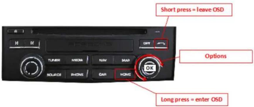

Use the PINK wire to power the Front and Side cameras. Set the OSD as follows:
Option 1 = CAM
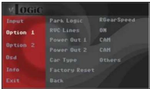
Setting the Front Camera
(Use the PINK wire to power the Front camera)


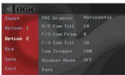
| OSD Menu | Menu Item Setting Description | ||
| Input FVC | OFF Front camera deactivated | ||
| ON | Switches to front camera if parking process is enabled and reverse gear is released | ||
| Option 1 Park | Logic | Intelligent | For vehicles with front-PDC. Enabled while parking process and up to 12 mph |
| RGearOnly | Enabled while parking process (not suitable for front camera operation) | ||
| RGearSpeed | Enabled while parking process and up to e.g. 7 mph (speed adjustable) | ||
| RGearTime Enabled while parking process and up to 20 seconds | |||
| Option 2 R/F | Cam ON XX Speed setting for deactivating of the camera image | ||
| Option 2 PDC | Graphic | OFF OEM PDC display of the vehicle deactivated | |
| Horizontal Vehicles with horizontal OEM PDC display | |||
| Vertical Vehicles with vertical OEM PDC display | |||
Note: You can deactivate the camera image by a long press (2 sec.) of the rotation knob.
Setting the Side Cameras
(Use the PINK wire to power the Side cameras)

| Input | Park Logic | RGearSpeed |
| Option 1 | RVC Lines | ON |
| Power Out 1 | CAM | |
| Option 2 | Power Out 2 | CAM |
| Osd | Car Type | Others |
| Info | Factory Reset | |
| Exit | Back |
| Input | PDC Graphic | Horizontal |
| Option 1 | R/F Cam Till | 10 |
| F/S Cam From | B | |
| Option 2 | F/S Cam Till | 20 |
| Osd | Cam Trigger | CAN |
| Info | Blinker Mode | OFF |
| Exit | Back |
| OSD Menu | Menu Item Setting Description | ||
| Option 2 R/F | Cam Till XX Speed setting for deactivating of the camera image | ||
| Option 2 F/S | Cam From XX | Speed range setting for front- and side cameras (minimum) | |
| Option 2 F/S | Cam Till XX | Speed range setting for front- and side cameras (maximum) | |
| Option 2 Blinker Mode | Front Cam Activation of the front camera image when the blinker is activated | ||
| Option 2 Cam | Trigger | CAN Rear gear and blinker signal detection over CAN Bus | |
| ANALOG | Rear gear and blinker signal detection over analogue +12V signals | ||
Notes: You can deactivate the camera image by a long press (2 sec.) of the rotation knob.
The camera activation via the blinker mode is only available for front camera or for the side view cameras. A parallel use of this function for all cameras is not possible.
Setting the Rear Aftermarket Camera
(Use the GREEN (12V Output) 2 wire to power the Front camera)
In the OSD Menu, set "Option 1" > menu item "Power Out 2" to "CAM"
If the aftermarket back up camera does not automatically switch on after putting the gear to reverse, you can use the analog setting instead. Connect the white wire from the VRFPR-66C harness to the analog reverse gear signal (+12V) wire. Set "Option 2" > "Cam Trigger" to Analog.
| V OGIC | ||
| Input | Park Logic | RGearSpeed |
| Option 1 | RVC Lines | ON |
| Power Out 1 | CAM | |
| Option 2 | Power Out 2 | CAM |
| Osd | Car Type | Others |
| Info | Factory Reset | |
| Exit | Back | |
| v LOGIC | ||
| Input | RVC | ON |
| FVC | ON | |
| Option 1 | Right VC/AU | ON |
| Option 2 | Left VC/AU | ON |
| Osd | BACK | |
| Info | ||
| Exit | ||
| v OGIC | ||
| Input | Park Logic | RGearSpeed |
| Option 1 | RVC Lines | ON |
| Power Out 1 | CAM | |
| Option 2 | Power Out 2 | CAM |
| Osd | Car Type | Others |
| Info | Factory Reset | |
| Exit | Back | |
| Input | PDC Graphic | Horizontal |
| Option 1 | R/F Cam Till | 10 |
| F/S Cam From | 0 | |
| Option 2 | F/S Cam Till | 20 |
| Osd | Cam Trigger | CAN |
| Info | Blinker Mode | OFF |
| Exit | Back |
| OSD Menu | Menu Item Setting Description | ||
| Input RVC | OFF Rear View | camera deactivated | |
| ON | Switches to rear-view camera if reverse gear is engaged or PDC is activate | ||
| Option 1 Park | Logic | Intelligent | For vehicles with PDC. Enabled while parking process and up to 12 mph (not suitable for front camera operation for vehicles without front PDC) |
| RGearOnly | Enabled while parking process (not suitable for front camera operation) | ||
| RGearSpeed | Enabled while parking process and up to e.g. 7 mph (speed adjustable) | ||
| RGearTime Ena bled while parking process and up to 20 seconds | |||
| Option 1 RVC | Lines ON Interactive Lane lines activated | ||
| Option 2 R/F | Cam Till XX Speed setting for deactivating of the camera image | ||
| Option 2 PDC | Graphic | OFF OEM PDC display of the vehicle deactivated | |
| Horizontal Vehicles with horizontal OEM PDC display | |||
| Vertical Vehicles with vertical OEM PDC display | |||
| Option 2 Cam | Trigger | CAN Rear gear and blinker signal detection over CAN Bus | |
| Analog Rear gear signal detection over analog +12V signals | |||
Note: You can deactivate the camera image by a long press (2 sec.) of the rotation knob.
| OSD Menu | Menu Item | Setting | Description |
| Input | RVC | OEM | If a factory rear-view camera is present. The interface turns off, if reverse gear is enabled and it displays factory rear-view camera |
| Intelligent | For vehicles with front-PDC. Enabled while parking process and up to 12 mph. | ||
| Option 1 | Park Logic | RGearSpeed | Enabled while parking process and up to e.g. 7 mph (speed adjustable) |
| RGearTime | Enabled while parking process and up to 20 seconds | ||
| Option 2 | R/F Cam Till | XX | Speed setting for deactivating of the camera image |
AV Source
You can use AV2 or AV3 to plug in an external video source. Please note that the vehicle needs to have a factory AUX Input for audio to be heard through the factory sound system.
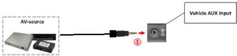
Use the PINK wire (12V OUTPUT 1) of the VRFPR-66C harness to power the external video source (max. 1A) of the AV source.
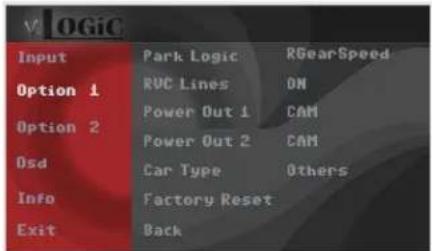
Go to the OSD menu and set "Option 1", menu item "Power Out 1" to "AVS" or "ACC".
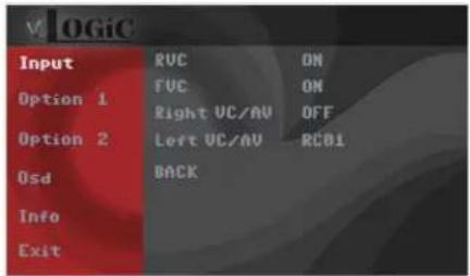
| OSD Menu | Menu Item Setting Description | ||
| Input | Right VC/AV | OFF No camera | / AV source connected |
| RCxx AV source | connected to the AV-2 input | ||
| Left VC/AV OFF | No camera / AV | source connected | |
| RCxx AV source | connected to the AV-3 input | ||
Note: Select "RC01" if AV source control function is via touchscreen and control knob is not used.
In the vehicle's Media menu, activate AUX Input (only necessary for AV source operation) to get sound through the vehicle's audio system. Press the "MEDIA" button for 3 to 5 seconds to go to AV mode.
A short press of the "MEDIA" button (or additionally on touchscreen the swipe gesture) will toggle through the video sources. Each short press will toggle to the next enabled input. If all inputs are enabled the order is:
Rear CAM > Front CAM > Right Cam/AV > Left Cam/AV > ... Inputs which are not enabled are skipped.
To exit AV mode, press the "MEDIA" button for 3 to 5 seconds or by a short press of "RADIO/NAV/TEL/PHONE/CAR" button.
Configurable Trigger Outputs
You can configure the both +12V trigger outputs separately in the OSD menu. The PINK wire (12V OUTPUT 1) is Power Out 1 and the GREEN wire (12V OUTPUT 2) is Power Out 2.
| Input | Park Logic | RGearSpeed |
| Option 1 | RVC Lines | ON |
| Option 2 | Power Out 1 | CAM |
| Power Out 2 | CAM | |
| Osd | Car Type | Others |
| Info | Factory Reset | |
| Exit | Back |
| OSD Menu | Menu Item Setting Description | |
| Option | Power Out 1 (PINK) | CAM +12V when the interface is on (red LED on) |
| ACC +12V when ignition is on | ||
| Cam +12V when camera input is activated (manually or automatically) | ||
| Power Out 2 (GREEN) | RGear +12V when reverse gear is engaged | |
| AVS +12V when camera / video input was manually activated | ||
| OFF Trigger output deactivated | ||
Tip: We recommend for all camera to use power out setting "Cam" and for AV source the power out setting of "AVS" or "ACC".
Interactive Lane Lines
The VRFPR-66C includes an Interactive Lane Lines function that is added to the aftermarket rear view camera. Use the OSD menu to activate this feature.
| V OGIC | ||
| Input | Park Logic | RGearSpeed |
| Option 1 | RVC Lines | ON |
| Power Out 1 | CAM | |
| Option 2 | Power Out 2 | CAM |
| Osd | Car Type | Others |
| Info | Factory Reset | |
| Exit | Back | |

natural_image
Pure geometric diagram showing intersecting lines and shaded regions without any text or symbols| OSD Menu | Menu Item Setting Description | ||
| Option | RVC Lines | OFF | Interactive lane lines deactivated |
| ON | Interactive lane lines activated | ||
| Car Type | CAYENNE / Others | Vehicle Type Selection | |
Interactive Lane Lines Settings
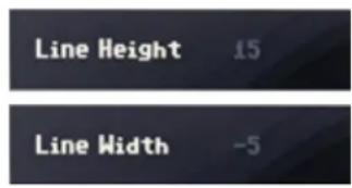
The height and width of the interactive lane lines can be set in the OSD menu. For this setting you must first activate the rear view camera level and push the "MENU"/ "HOME"(Porsche) button for 2 seconds to activate the settings menu. With the rotation knob you can select the menu point "Line Height" to change the height of the interactive lane lines and with menu point "Line Width" the width of the lines. Click "Exit" to leave the settings menu.
Picture Settings
The camera picture can be set in the OSD menu. For this setting you must first activate the camera level and push the "MENU"/"HOME" (Porsche) button for 2 seconds to activate the settings menu. With the rotation knob you can select and change the "Brightness", "Contrast", "Saturation", Hue" and "Sharpness". Click "Exit" to leave the settings menu.

Note: The picture settings will be retained for every camera input separately.
OSD Settings
You can change the basic configurations of the interface in the OSD (on screen display).

| OSD Menu | Menu Item Setting Description | ||
| OSD | POS. X 0-xxx Horizontal position of the OSD | ||
| POS. Y 0-xxx Vertical position of the OSD | |||
| Size | Small Small OSD menu window | ||
| Large Large OSD menu windows | |||
| Osd TimeOut 2-20 Time setting for automatic OSD shutoff | |||
| Info Version X | XX.XX Displays the current SW-version | ||
| Option 1 | Factory Reset | Reset to factory default settings | |

VEHICLE APPLICATIONS:
| Porsche2017 - Up2017 - Up2017 - Up2017 - Up | BoxsterCayenneCayman911 | PCM 4.0 |

natural_image
Interior view of a modern car dashboard with steering wheel, dashboard display, and digital navigation screen (no visible text or symbols)2017 Boxster

natural_image
Interior view of a modern car dashboard with visible steering wheel, dashboard display, and illuminated brand logo (no readable text or symbols)2017 911

natural_image
Interior view of a beige car dashboard with digital navigation and steering wheel (no visible text or symbols)2017 Cayenne
Brand : CRUX
Model : VRFPR-66C
Category : Interface de caméra automobile