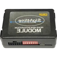
VRFPR-66F - Interface de caméra automobile CRUX - Free user manual and instructions
Find the device manual for free VRFPR-66F CRUX in PDF.


| Product Type | Vehicle Interface Module |
| Dimensions | 5.5 x 3.5 x 1.2 inches (140 x 90 x 30 mm) |
| Weight | 0.5 lbs (225 g) |
| Power Input | 12V DC, 1A |
| Power Consumption | 5W max |
| Video Input | Composite video (RCA), NTSC/PAL |
| Video Output | Composite video (RCA), 1Vp-p |
| Audio Support | None |
| Operating Temperature | -20°C to 70°C (-4°F to 158°F) |
| Main Functions | Backup camera signal conversion, parking guide line overlay, auto-switch on reverse gear |
| Compatibility | Select CRUX interface modules and vehicles (see manual) |
| Installation | Plug-and-play, no cutting wires |
| Maintenance & Cleaning | Wipe with dry soft cloth; avoid liquids |
| Safety | Use only with 12V negative ground systems; disconnect battery before installation |
| Spare Parts & Repairability | Contact CRUX support for approved replacement parts; no user-serviceable parts inside |
| General Information | Designed for aftermarket rearview camera integration with factory radios |
Frequently Asked Questions - VRFPR-66F CRUX
User questions about VRFPR-66F CRUX
0 question about this device. Answer the ones you know or ask your own.
Ask a new question about this device
Download the instructions for your Interface de caméra automobile in PDF format for free! Find your manual VRFPR-66F - CRUX and take your electronic device back in hand. On this page are published all the documents necessary for the use of your device. VRFPR-66F by CRUX.
USER MANUAL VRFPR-66F CRUX
• Rear & Front View Camera Inputs
- Optional coding of ParkAssist to retrofit factory PDC
- Automatically switches screen to Rear-view when Reverse gear is engaged and to Front camera view when gear is engaged to drive
- Manual activation of the front camera using the steering wheel control button
- Plug & Play Installation
• Video in Motion function
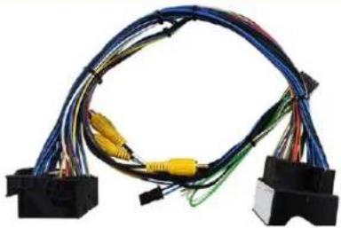
PARTS INCLUDED:
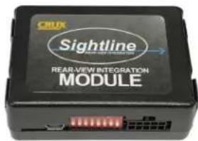
natural_image
Coiled electrical cable with wires and connectors, no visible text or symbols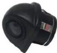
VRFPR-66F Module VRFPR-66F Harness CUL-16 Rear-View Camera
INSTALLATION DIAGRAM:

flowchart
graph TD
    A["Male Quadlock Connector behind the headunit"] --> B["VRFPR-66F Harness"]
    B --> C["OEM Rear-View Camera"]
    B --> D["Rear-View Camera Input"]
    B --> E["Front-View Camera Input"]
    C --> F["Rear-View Camera (CUL-16 Included)"]
    D --> G["Front-View Camera (not Included)"]
    E --> H["Rear Camera Output 12V (GREEN)"]
    E --> I["Front Camera Output 12V (WHITE)"]
    J["Female Quadlock Vehicle Harness"] --> K["Sightline MODULE"]
    K --> L["Output"]
    style A fill:#f9f,stroke:#333
    style B fill:#ccf,stroke:#333
    style C fill:#cfc,stroke:#333
    style D fill:#fcc,stroke:#333
    style E fill:#cff,stroke:#333
    style F fill:#ffc,stroke:#333
    style G fill:#ffc,stroke:#333
    style H fill:#cfc,stroke:#333
    style I fill:#cfc,stroke:#333
DIP SWITCH SETTINGS:
| Navigation System DIP 1 DIP2 DIP3 DIP4 DIP5 DIP6 | |||||||
| PCM3 with VIM Activated ON ON | OFF OFF OFF | OFF | |||||
| PCM3 with VIM Deactivated OFF | ON OFF OFF | OFF OFF | |||||
| PCM3.1 with VIM Activated ON ON | OFF OFF OFF | ON | |||||
| PCM3.1 with VIM Deactivated OFF | ON OFF OFF | OFF ON | |||||
DIP SWITCH FUNCTIONS:
DIP 1 = Video in Motion Activation
DIP 2 = ON for OEM Rear View Camera / OFF for Aftermarket Rear View Camera
DIP 3 = Rear View Camera Coding (see page 3)
DIP 4 = ParkAssist Coding for PCM3.1 systems only (see page 4)
DIP 5 = Camera/ParkAssist Coding (see page 5)
DIP 6 = CAN Bus Termination
INSTALLATION INSTRUCTIONS:
The interface module is installed behind the headunit.
CONNECTING THE INTERFACE MODULE
- Remove the headunit.
- Connect the female 12-Pin Molex connector of the VRFPR-66F T-harness to the interface module.
- Unplug the female Quadlock connector from behind the headunit and plug it into the VRFPR-66F T-harness.
- Plug the male Quadlock of the VRFPR-66F T-harness to the headunit.
CONNECTING THE FACTORY REAR-VIEW CAMERA (Compatible with NTSC cameras only)
- If the OEM rear-view camera will be used, plug in the male RCA labeled "OEM Rear-View Camera" to the female RCA labeled "Rear-View Camera".
CONNECTING THE AFTERMARKET CAMERAS (Compatible with NTSC cameras only)
- If using an aftermarket rear-view camera, install the aftermarket camera behind the vehicle and run the cable towards the radio. Plug in the male RCA of the aftermarket rear-view camer to the female RCA labeled "Rear-View Camera".
- Connect the GREEN wire on the T-harness to the 12V power wire of the aftermarket camera. The GREEN wire will provide 12 volts power to the camera when the reverse gear is engaged. Power will deactivate automatically when the gear is set to drive and speed reaches to 12 MPH.
- If an aftermarket front-view camera will be used, install the camera per manufacturer's installation instructions and run the extension cable towards the radio. Plug in the male RCA of the aftermarket rear-view camer to the female RCA labeled "Front-View Camera".
- Connect the WHITE wire on the T-harness to the 12V power wire of the aftermarket camera. The WHITE wire will provide 12 volts power to the camera when the gear is set to drive. Power will deactivate automatically when the speed reaches 12 MPH.
CODING THE RADIO FOR CAMERA FUNCTION:
PCM3.1 Systems
It is necessary to code the rear-view camera input of the PCM3.1 system for use with an aftermarket rear-view camera.
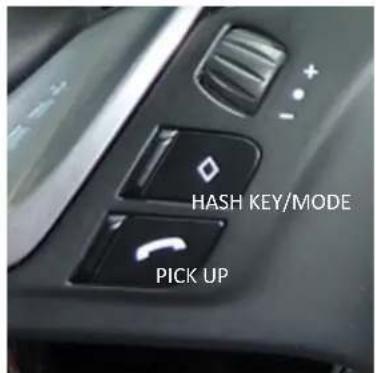

Left side Steering Wheel Buttons Right side Steering Wheel Buttons
- Turn ignition to ON.
- Wait until the headunit has completely booted and is in the home screen.
- Make sure that the LEDs on the interface module is visible during this process. The LEDs are inside the module and are visible through the side of the male 8-pin Molex connector.
- Please observe the proper coding sequence: First press and hold the HASH KEY/MODE then press and hold the PICK UP button. Continue to hold both buttons and check if the RED and BLUE LEDs are blinking. The PCM system will reset after 5-10 seconds.
- Release both buttons.
- The RED and BLUE LEDs will light up solid.
- "Rear-View Camera" will show on the radio menu option after a successful coding.
To decode the aftermarket rear-view camera from the system, follow the steps below.
- Turn ignition to ON.
- Wait until the headunit has completely booted and is in the home screen.
- Make sure that the LEDs on the interface module is visible during this process. The LEDs are inside the module and are visible through the side of the male 8-pin Molex connector.
- Please observe the proper decoding sequence: First press and hold the HASH KEY/MODE button then press and hold the HANG UP button. Continue to hold both buttons and check if the RED and BLUE LEDs are blinking. The PCM system will reset after 5-10 seconds.
- Release both buttons.
- The RED and BLUE LEDs will light up solid.
- "Rear-View Camera" will no longer show on the radio menu option after a successful decoding.
CODING THE RADIO FOR PARKASSISTANT FUNCTION:
PCM3.1 Systems
It is necessary to code the ParkAssist of the PCM3.1 system to retrofit the factory PDC.
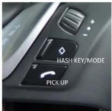
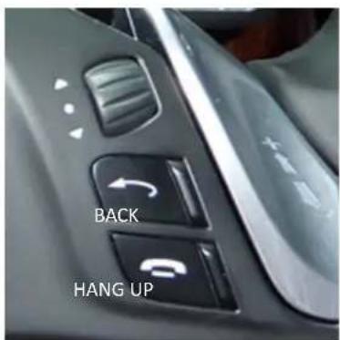
Left side Steering Wheel Buttons Right side Steering Wheel Buttons
- Turn ignition to ON.
- Wait until the headunit has completely booted and is in the home screen.
- Make sure that the LEDs on the interface module is visible during this process. The LEDs are inside the module and are visible through the side of the male 8-pin Molex connector.
- Please observe the proper coding sequence: First press and hold the BACK button then press and hold the PICK UP button. Continue to hold both buttons and check if the RED and BLUE LEDs are blinking. The PCM system will reset after 5-10 seconds.
- Release both buttons.
- The RED and BLUE LEDs will light up solid.
- "ParkAssist" will show on the radio menu option after a successful coding.
To decode the ParkAssist from the system, follow the steps below.
- Turn ignition to ON.
- Wait until the headunit has completely booted and is in the home screen.
- Make sure that the LEDs on the interface module is visible during this process. The LEDs are inside the module and are visible through the side of the male 8-pin Molex connector.
- Please observe the proper decoding sequence: First press and hold the BACK button then press and hold the HANG UP button. Continue to hold both buttons and check if the RED and BLUE LEDs are blinking. The PCM system will reset after 5-10 seconds.
- Release both buttons.
- The RED and BLUE LEDs will light up solid.
- "ParkAssist" will no longer show on the radio menu option after a successful decoding.
CODING THE RADIO FOR VEHICLES WITHOUT STEERING WHEEL CONTROLS:
PCM3.1 Systems
It is possible to code and decode the radio for an aftermarket rear-view camera and ParkAssist functions on vehicles without steering wheel controls. This is done using DIP switch #3, #4 and #5.
| DIP# FUNCTION ON OFF | ||
| 3Rear-View Camera Coding Decoding | ||
| 4ParkAssist Coding Decoding | ||
| 5Activation of Coding/Decoding Process 5 sec. = Start Default setting |
- Set DIP #5 to OFF.
- Turn ignition to ON.
- Wait until the headunit has completely booted and is in the home screen.
- Make sure that the LEDs on the interface module is visible during this process. The LEDs are inside the module and are visible through the side of the male 8-pin Molex connector.
- Set DIP #3 and DIP #4 to the desired function (coding or decoding)
- Set DIP #5 to the ON position for 5 seconds.
- During configuration, check if the RED and BLUE LEDs are blinking. The PCM system will reset after 5-10 seconds.
- The RED and BLUE LEDs will light up solid.
- "Rear-View Camera" and/or "ParkAssist" will show on the radio menu option after a successful coding.
NOTES:
- After a coding or decoding process, wait for 60 seconds before another coding or decoding process can be made.
- If there is a n existing factory PDC in the vehicle, set DIP #4 to the ON position while coding otherwise the factory PCD will be decoded.
CODING THE RADIO FOR REAR-VIEW CAMERA ON PORSCHE CAYENNE WITH PCM3 SYSTEM:
| DIP# FUNCTION ON OFF | ||
| 3Rear-View Camera Coding Decoding | ||
| 5ParkAssist Coding Decoding |
- Set DIP #5 to OFF.
- Turn ignition to ON.
- Wait until the headunit has completely booted and is in the home screen.
- Make sure that the LEDs on the interface module is visible during this process. The LEDs are inside the module and are visible through the side of the male 8-pin Molex connector.
- Set DIP #3 to the desired function (coding or decoding)
- Set DIP #5 to the ON position for 5 seconds.
- During configuration, check if the RED and BLUE LEDs are blinking. The PCM system will reset after 5-10 seconds.
- The RED and BLUE LEDs will light up solid.
- "Rear-View Camera" will show on the radio menu option after a successful coding.
NOTE:
- After a coding or decoding process, wait for 60 seconds before another coding or decoding process can be made.
LED INFORMATION:
| LED STATUS DESCRIPTION | ||
| Blue | Solid Light | CAN Bus Communication OK |
| Flashing | CAN Bus Search | |
| Red | Solid Light | Rear-View Camera is Coded |
| Flashing | Rear-View Camera is Decoded | |
MANUAL ACTIVATION OF FRONT CAMERA:
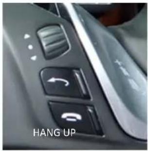
Press the HANG UP button on the steering wheel control for 3 seconds to manually activate or deactivate the front camera.
natural_image
Close-up of a car's interior control panel with directional buttons and a 'HANG UP' text label (no other readable text or symbols)VEHICLE APPLICATIONS:
Porsche
2014 – 2016 Macan
2014-2016 911 GT3
2013-2016 911
2014 – 2016 Boxster
2009 – 2016 Cayenne
2014 – 2016 Cayman
2010 – 2016 Panamera
Notes:
- PCM software version MUST be 4.xx or higher.
- Video in Motion feature does not work on the internal DVD video player.
Compatible Navigation Systems:
PCM 3.1
PCM 3 (for Cayenne Only)

6 of 6
rev.031220

- DIP SWITCH SETTINGS:
- DIP SWITCH FUNCTIONS:
- INSTALLATION INSTRUCTIONS:
- CONNECTING THE INTERFACE MODULE
- CONNECTING THE FACTORY REAR-VIEW CAMERA (Compatible with NTSC cameras only)
- CONNECTING THE AFTERMARKET CAMERAS (Compatible with NTSC cameras only)
- CODING THE RADIO FOR CAMERA FUNCTION:
- PCM3.1 Systems
- CODING THE RADIO FOR PARKASSISTANT FUNCTION:
- CODING THE RADIO FOR VEHICLES WITHOUT STEERING WHEEL CONTROLS:
- NOTES:
- CODING THE RADIO FOR REAR-VIEW CAMERA ON PORSCHE CAYENNE WITH PCM3 SYSTEM:
- NOTE:
- LED INFORMATION:
- MANUAL ACTIVATION OF FRONT CAMERA:
- VEHICLE APPLICATIONS:
- Porsche
- Compatible Navigation Systems:
Brand : CRUX
Model : VRFPR-66F
Category : Interface de caméra automobile