
GI 535 DV IPI - Fireplace JOTUL - Free user manual and instructions
Find the device manual for free GI 535 DV IPI JOTUL in PDF.


| Product Type | Direct Vent Gas Fireplace Insert |
| Brand | Jøtul |
| Model | GI 535 DV IPI |
| Fuel Type | Natural Gas (factory default); Propane (conversion kit included) |
| Input Rating (NG) | Max 32,000 BTU/hr; Min 11,500 BTU/hr |
| Input Rating (LP) | Max 31,500 BTU/hr; Min 11,000 BTU/hr |
| Efficiency (Steady State) | 74.28% (NG); 76.39% (LP) |
| Efficiency (AFUE) | 70.03% (NG); 72.00% (LP) |
| Ignition System | Intermittent Pilot Ignition (IPI) with Smart Start; Continuous Pilot (CPI) selectable |
| Control System | Proflame 2 remote control with thermostat, flame modulation, blower, and accent light control |
| Blower (Air Circulation) | Integrated cross-flow blower, 120 CFM |
| Power Requirement | 120 VAC (backup 6V DC battery pack for burner operation during power outage) |
| Required Fireplace Opening (Min) | Height 20" (50.8 cm), Width 30" (76.2 cm), Depth 15 3/8" (39 cm) |
| Venting System | Direct vent with 3" diameter listed flexible liners; max vent height 35 ft (10.67 m); no horizontal runs |
| Safety Features | Hot glass barrier, automatic shutdown on pilot failure, childproof remote lockout, certified to ANSI Z21.88-2016, CSA 2.33-2016 |
| Maintenance | Annual inspection; clean glass with non-abrasive cleaner; keep control compartments free of dust |
| Spare Parts Availability | Full range of replacement parts and accessories through authorized Jøtul dealers |
| Warranty | 5 years cast iron/steel/firebox; 2 years burner/panels/enamel; 1 year electrical/gas components |
| Certifications | Intertek, EPA (via CSA), Canada Energy Performance Verified |
| Log Set Options | Traditional Log Set and Beach Fire Log Set (both included? No, ordered separately) |
Frequently Asked Questions - GI 535 DV IPI JOTUL
User questions about GI 535 DV IPI JOTUL
0 question about this device. Answer the ones you know or ask your own.
Ask a new question about this device
Download the instructions for your Fireplace in PDF format for free! Find your manual GI 535 DV IPI - JOTUL and take your electronic device back in hand. On this page are published all the documents necessary for the use of your device. GI 535 DV IPI by JOTUL.
USER MANUAL GI 535 DV IPI JOTUL
natural_image
Grid-patterned panel with uniform square cells, no visible text or symbolsJøtul GI 535 DV IPI New Harbor
Direct Vent Fireplace Insert
Smart Start Ignition System with
Pilot-on-Demand
Installation and Operation Instructions
Certified to ANSI Z21.88-2016 • CSA 2.33-2016 and
CAN/CGA 2.17-M-17.
INSTALLER: Leave this manual with the appliance.
CONSUMER: Keep this manual for future reference.
WARNING:
FIRE OR EXPLOSION HAZARD. Failure to follow safety warnings exactly could result in serious injury, death, or property damage.
- Do not store or use gasoline or other flammable vapors and liquids in the vicinity of this or any other appliance.
-
WHAT TO DO IF YOU SMELL GAS
-
Do not try to light any appliance.
- Do not touch any electrical switch; do not use any phone in your building.
- Immediately call your gas supplier from a neighbor's phone. Follow the gas supplier's instructions.
- If you cannot reach your gas supplier, call the fire department.
- Installation and service must be performed by a qualified installer, service agency or the gas supplier.
- In the Commonwealth of Massachusetts, a carbon monoxide (CO) detector shall be installed in the same room as the appliance.
This appliance may be installed in an aftermarket, permanently located, manufactured home or mobile home, where not prohibited by local codes.
This appliance is only for use with the types of gas indicated on the rating plate. A conversion kit is supplied with the appliance.
! DANGER

natural_image
Abstract graphic with flame and globe elements (no text or symbols)HOT GLASS WILL
CAUSE BURNS
DO NOT TOUCH GLASS
UNTIL COOLED.
NEVER ALLOW CHILDREN
TO TOUCH GLASS.
A barrier designed to reduce the burn hazard from the glass viewing area is provided with this appliance and shall be installed for the protection of children and other at-risk individuals.
THIS OWNER'S MANUAL PROVIDES INFORMATION TO ENSURE SAFE INSTALLATION AND EFFICIENT, DEPENDABLE OPERATION OF YOUR FIREPLACE INSERT. PLEASE READ THESE INSTRUCTIONS IN THEIR ENTIRETY AND MAKE THEM AVAILABLE TO ANYONE USING OR SERVICING THIS GAS INSERT.
DO NOT ATTEMPT TO ALTER OR MODIFY THE CONSTRUCTION OF THIS APPLIANCE OR ITS COMPONENTS. ANY MODIFICATION OR ALTERATION WILL VOID THE WARRANTY, CERTIFICATION AND LISTING OF THIS APPLIANCE.
THIS HEATER MUST BE INSTALLED AND MAINTAINED BY A QUALIFIED SERVICE AGENCY.
Suggested Tools for Installation and Service
• External regulator (for Propane only)
- Piping which complies with local code
- A manual shut-off valve is included with this appliance, however, an additional T-Handle valve may be required in Massachusetts
- Sediment trap - if required by code
- Tee joint
- Pipe wrench
- Pipe sealant
- 10 mm open end wrench
• 1/2", 7/16" open end wrench
• Phillips head screwdriver
- Flat head screwdriver
- 1/4" nut driver
- Work Gloves
- Safety glasses
- Torx T-20 screwdriver
- Tin snips
- Glass Latch Tool
Retain and store as shown in fig. 7.3.
INSTALLER NOTE:
Leave this manual with the homeowner and instruct them on basic operation procedures before leaving the premises.
It is normal for some smoke and odor to occur during initial operation as manufacturing materials cure under heat. Please direct the homeowner to page General Information, page 5, for details how to alleviate this condition and properly cure the paint and log set materials.

Intertek EP5010378
CANADIAN ENERGY PERFORMANCE VERIFIED RENDEMENT ÉNERGÉTIQUE VÉRIFIÉ
Installation Requirements for the Commonwealth of Massachusetts THIS PRODUCT MUST BE INSTALLED BY A LICENSED MASTER OR JOURNEYMAN PLUMBER OR GAS-FITTER WHEN INSTALLED IN THE COMMONWEALTH OF MASSACHUSETTS.
-
If there is not one already present, on each floor level where there are bedroom(s), a carbon monoxide detector and alarm shall be placed in the living area outside the bedroom(s). The carbon monoxide detector shall comply with NFPA 720 (2012 Edition).
-
A carbon monoxide detector shall:
a) Be located in the room that houses the appliance or equipment;
b) Be either hard-wired or battery powered or both; and
c) Shall comply with NFPA 720 (2012 Edition).
- A Product-approved vent terminal must be used, and if applicable, a Product-approved air intake must be used. Installation shall be in strict compliance with the manufacturer's instructions. A copy of the installation instructions must remain with the appliance or equipment at the completion of the installation.
NATIONAL FIREPLACE INSTITUTE

CERTIFIED
www.sftcertified.org
We recommend that our gas products be installed and serviced by professionals who are certified in the U.S. by the National Fireplace Institute® (NFI) as NFI Gas Specialists.
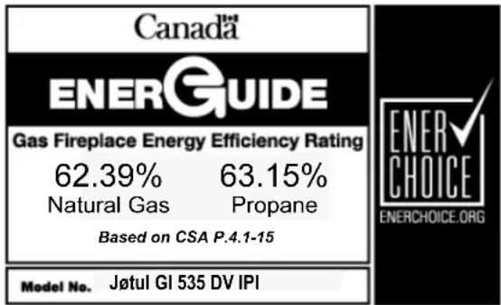
Table of Contents
- Unpacking the Fireplace ....3
- Specifications 4
- General Information......5
- Safety Information ......6
- Installation......7
5.1 Fireplace Requirements.... 8
5.2 Hearth & Clearance Protection ....8
5.3 Clearances....9
- Vent Guidelines....10
6.1 Masonry Fireplaces .....11
6.2 Factory-built Fireplaces......12
6.3 Vent Connection ....13
- Fireplace Assembly....14
7.1 Gas Connection....14
7.2 Gas Pressure Test....14
7.3 Fuel Conversion....16
7.4 High Altitude Adjustment......19
7.5 Final Positioning....20
7.6 Brick Panel Kits....20
7.7 Reflective Glass Panel Kit 21
7.8 Log Set Installation....22
7.9 Traditional 22
7.10 Beach Fire 24
7.11 Backer Plate Installation....27
7.12 Trimable Backer Plate Install 28
7.13 Hidden Hanger Bracket 26
7.14 Front Cast Iron Overlay 28
- Operation....29
8.1 Initial System Check....29
8.2 Fireplace Operation 31
8.3 Remote Control Functions ...... 32
- Maintenance ....37
9.1 General and Annual Cleaning......37
9.2 Accent Lamp Bulb Replacement .....37
9.3 Battery Replacement 37
9.4 Glass Care and Replacement......38
-
Illustrated Part Breakdowns....39
-
Appendix 44
11.1 Approved Vent Manufacturers...... 44
11.2 Burner Re-installation....44
11.3 Proflame 2 Wiring Diagram....45
11.4 Warranty Statement......46 - Lighting Instructions 47
1.0 Unpacking the Fireplace Insert
- Thoroughly inspect the appliance for shipping damage and immediately contact the dealer if any is found.
-
A Miscellaneous Hardware Kit is packed within the firebox crate with this manual. Confirm these contents:
-
Fuel Conversion Kit, LP
- Fireplace Conversion Notice Plate
• Rock Wool Ember Fibers -
Remote Transmitter
• Transmitter Wall Bracket
• Four, 1.5 v AA IFC Back-up Batteries
• Three, 1.5 v AAA Remote Transmitter Batteries
• Safety Screen Barrier Guidelines -
Detach the firebox from the pallet with removal of the attachment bracket screws at each side of the firebox base.
- Remove the Latch Tool from the shipping pallet. Use it to disengage the two spring latches from the glass frame as shown in fig. 1. Engage the tool prong with the Latch receiver hole and pull the latch hook forward and up to detach it from the glass frame slot. Pivot the top of the frame forward to disengage it from the bottom corners of the firebox. Set the glass frame out of the way.
- The Log Set is shipped separately. Set it out of the way until you are ready to install it.
- PRE-INSTALLATION FIT UP: Leveling bolts are located at each corner of the firebox base to allow a maximum 1/2" adjustment to correct hearth irregularities. Before assembly, locate the firebox in its final position within the fireplace and adjust the leveling bolts as necessary to level and plumb the unit. Front bolts are accessible in each side compartment through the fireplace front. Tip the firebox forward to adjust the rear bolts out of the base.
Pull the unit back out of the fireplace and read the installation requirements in this manual before proceeding with assembly and installation.
- The remote control IFC and hand-held Transmitter have been synchronized at the factory before the batteries are removed for shipping. See Sect. 8.1, page 25, for complete installation instructions.

Figure 1.1 Pull each Spring Latch OUT and UP to disengage it from the Glass Frame. Swing the glass frame down.
Jøtul GI 535 DV IPI (POD) Direct Vent Gas Fireplace Insert
Manufactured and Distributed by:
Jøtul North America
Gorham, Maine USA
2.0 Specifications
Input Rates:
Natural Gas
32,000 BTU/hr. maximum input
11,500 BTU/hr. minimum input
Propane
31,500 BTU/hr. maximum input
11,000 BTU/hr. minimum input
Inlet Pressure: MIN. MAX.
Natural Gas: 5.0 WC (1.00 kPa) 7.0 WC (1.74 kPa)
Propane: 11.0 WC (3.00 kPa) 14.0 WC (3.48 kPa)
Manifold Pressure: MIN . MAX.
Natural Gas: 1.6 WC (0.27 kPa) 3.5 WC (0.95 kPa)
Propane: 6.4 WC (0.72 kPa) 10.0 WC (2.74 kPa)
Orifice Sizes:
Altitude: 0 - 2000 ft. (0-610 m) NG LP
Front Burner, Left: 1.95 mm 3/64"
Rear Burner, Right: #48 #56
Altitude: 2000 - 4500 V3 V3 ft. (610-1370 m)
Front Burner, Left: #48 #56
Rear Burner, Right: #49 #57
NG LP
Steady State Efficiency: 74.28% 76.39%
A.F.U.E. Efficiency: 70.03% 72.00%
CSA P4.1-15 Fireplace Efficiency: 62.39% 63.15%
Electronic Ignition (IPI) or Continuous Pilot (CPI)
Test Standards
This appliance complies with National Safety standards and is tested and listed by Intertek Testing Services NA Inc. of Middleton, Wisconsin.
In addition, the Jøtul GI 535 DV IPI gas fireplace insert has been tested and listed as a direct vent gas fireplace heater and listed to ANSI z21.88-2016 • CSA 2.33-2016 “Standard for Vented Gas Fireplace Heaters” and CAN/CSA 2.17-M91 “Standard for Gas-Fired Appliances for use at High Altitudes”.
Accessories
• Traditional Red Brick Panel Kit.....#157877
- Brownstone Brick Panel Kit....#157878
- Reflective Glass Panel Kit ....#157879
- Fluted Panel Kit ....#158082
- Cast Iron Overlay, Matte Black ....#157899
- Cast Iron Overlay, Brown Majolica Enamel ....#157900
• Steel Overlay, Black Power Coat.....#157920
- Steel Overlay, Bronze Powder Coat ....#157921
• Steel Overlay, Jøtul Iron Powder Coat.....#157922
- Fuel Conversion Kit - NG to LP (included) ...... #157784
- Fuel Conversion Kit - LP to NG....#157785
• High Altitude Adjustment Kit - LP ...... #157886
• High Altitude Adjustment Kit- NG.....#157887
- Hidden Hanger Bracket Kit* ....#157888
- Hard Wire Kit ....#158043
- Extension Power Cord ......#223253
*Required if no Backer Plate is needed
Log Set Options
• Traditional Log Set ....#158094
- Beach Fire Log Set ....#158095
Backer Plate Options
• All Backer Plates include Hanger Brackets for attaching the Cast Iron or Steel Surround Overlays
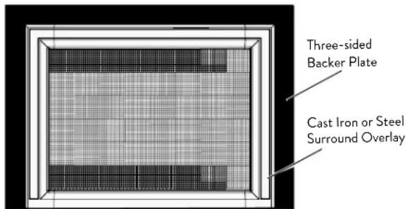
Three-sided Backer Plate
• 36" W x 24 1/4"H (91.4 x 61.6 cm) ......#157889
- 38"W x 28"H (96.5 x 71.1 cm)....#157890
- 40"W x 30"H (101.6 x 76.2 cm)....#157891
Three-sided Trimmable Backer Plate
- 46" W x 34" H (116.8 x 86.4 cm) ....#157892

Four-sided Trimmable Backer Plate
- 46" W x 34" H (116.8 x 86.4 cm) ...... #157893
3.0 General Information
THIS HEATER MUST BE INSTALLED AND MAINTAINED BY A QUALIFIED SERVICE AGENCY.
DO NOT ATTEMPT TO ALTER OR MODIFY THE CONSTRUCTION OF THIS APPLIANCE OR ITS COMPONENTS. ANY MODIFICATION OR ALTERATION WILL VOID THE WARRANTY, CERTIFICATION AND LISTING OF THIS APPLIANCE.
IMPORTANT: SAVE THESE INSTRUCTIONS.
- The installation and repair of this appliance must be done by a qualified service person. Failure to properly install and maintain this heater could result in an unsafe or hazardous installation, which may result in a fire, explosion, property damage, personal injury or loss of life.
- This appliance should be inspected before use and at least annually. More frequent cleaning may be required due to excessive lint from carpeting, bedding material, pet hair, dander, etc. It is imperative that control compartments, burners and circulating air passageways of the appliance be kept clean.
- This appliance may be installed in an aftermarket permanently located, manufactured (mobile) home, where not prohibited by local codes.
This appliance is only for use with the type(s) of gas indicated on the rating plate. This appliance is not convertible for use with other gases, unless a certified kit is used.
- The installation must conform to local codes. Your local Jøtul authorized dealer can assist you in determining what is required in your area for a safe and legal installation. Some areas require a permit to install a gas burning appliance. Always consult your local building inspector or authority having jurisdiction to determine what regulations apply in your area.
In the absence of local codes, the installation requirements must comply with the current National codes. In the U.S., these requirements are established in the National Fuel Code, ANSI-Z223.1.(NFPA 54). In Canada, the codes have been established in CAN/CGA B149 Fuel Installation Code.
- Do not operate this fireplace if any part of it has been under water.
Immediately call a qualified service technician to inspect the heater and to replace any part of the control system and any gas control which has been under water.
-
Do not operate the fireplace with the glass front removed, cracked, scratched, or broken. Replacement of the glass should be done by a licensed or qualified service person. Only remove glass for routine service. Always handle glass carefully.
-
Notify your insurance company before proceeding with installation of this fireplace.
- It is normal that burner ignition and extinction be accompanied by a muffled "woof" or "thud" noise. Discontinue use and call a qualified service technician if these functions become unusually loud or disturbing.

INITIAL FIRING PROCESS - Heat-curing the Paint and Log Set
This appliance has been painted with the highest quality coating used in the hearth industry. Manufacturers have selected this product because it has been proven durable, colorfast, and beautiful at temperatures up to 1200°F/650°C. Although the paint has been air-dried at the factory, it must be heat-cured in order to maximize its coating properties and durability. This process occurs during initial firing of the appliance and will generate odor and some visible smoke.
We recommend you do the following BEFORE operating the appliance for the first time:
- Ventilate: Open doors and windows and use a fan to circulate fresh air throughout the room.
- Vacate: The fumes are non-toxic, but can be uncomfortable for babies, small children, pregnant women, elderly, pets, or anyone having breathing difficulties.
Gas Appliance Curing Process
- After the installer has confirmed proper burner function at all heat levels, the homeowner should operate the appliance at a low setting for 2-4 hours, followed by 2-4 hours operation at a high setting.
- Off-gassing by paint and log set ceramic material may leave a white, powdery deposit on the inside surface of the glass panel. This residue must be removed using a non-abrasive household glass cleaner or warm water to prevent permanent etching of the glass.
DO NOT USE AMMONIA-BASED CLEANERS.
See Section 8, OPERATION for detailed, day-to-day operating procedures.
4.0 Safety Information
Due to the high operating temperatures this appliance should be located out of traffic and away from furniture, draperies, etc. Maintain proper clearance to combustible mantels and fireplace trim.
Children and adults should be alerted to the hazards of high surface temperatures and should stay away to avoid burns or clothing ignition.
■ Young children should be supervised while they are in the same room as the appliance. Toddlers, young children and others may be susceptible to accidental contact burns. A physical barrier, such as a child guard, is recommended to be used if there are at-risk individuals in the house. To restrict access to a fireplace or stove, install an adjustable safety gate to keep toddlers, young children and other at-risk individuals out of the room and away from hot surfaces.
A safety barrier is provided with this appliance designed to reduce the risk of burns from the hot viewing glass and shall be installed for the protection of children and other at-risk individuals.
If the barrier becomes damaged, the barrier shall be replaced only with the Jøtul barrier part number 225731.
■ Any safety screen, glass panel, guard, or barrier removed for servicing an appliance must be replaced prior to operating the appliance.
■ Clothing or other flammable materials should not be placed on or near the fireplace.
■ Never allow anyone to use the fireplace if they are unfamiliar with its operation.
■ NEVER store or use gasoline or any other flammable vapors or liquids in the vicinity of the fireplace.
■ Never burn any solid materials (wood, cardboard, paper, coal, etc.) in this gas fireplace. Use with natural gas or propane fuel ONLY.
■ Do not slam or strike the glass panel.
This appliance is NOT for use with aftermarket glass doors. This appliance is approved for use only with the surround panel options listed on page 4 of this manual.
■ Wear gloves and safety glasses while installing or performing maintenance procedures on this appliance.
This fireplace insert is specifically designed for use with 3" diameter Listed flexible gas liners.

Electrical Hazards
■ Be aware of electrical wiring locations when cutting holes in walls and ceilings for termination.
The blower must be electrically grounded in accordance with local codes or, in the absence of local codes, with the current ANSI/NFPA 70, National Electrical Code or CSA C22.1-Canadian Electrical Code.
The blower is supplied with a three-prong (grounding) plug for protection against shock hazard and should be plugged directly into a properly grounded three-prong receptacle.
DO NOT CUT OR REMOVE THE GROUNDING PRONG FROM THE PLUG.
■ Always disconnect the power supply when performing any service on the fireplace, including battery replacement.
Power Requirement
This appliance requires 120 VAC power to operate the blower, accent lamp, and electronic ignition.
Four, AA batteries provide back-up power to operate the burner in case of a power outage. The blower and accent lamp will not function with loss of power.
Leg Leveling Note:
This appliance is equipped with four leveling bolts; the front two are adjusted from inside the firebox, and the rear bolts are adjusted by tipping the firebox and unscrewing them from the base.
Also note that use of the leveling bolts will affect required minimum clearance to combustible top trim and mantle construction. See the figures and tables on pages 8 and 9.


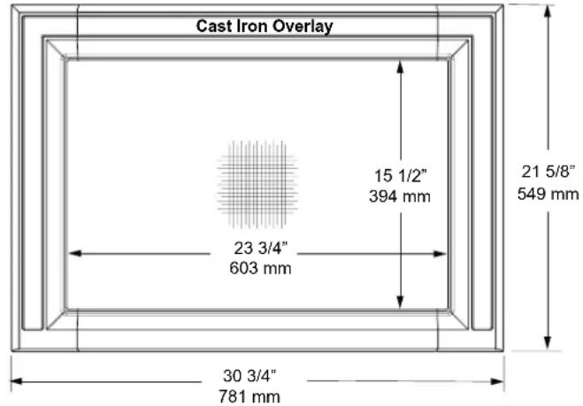
Figure 5.1. Firebox dimensions.
5.0 Installation
Requirements
This insert can be installed in most solid fuel burning fireplaces of either masonry construction or a prefabricated factory built fireplace.
Prior to any installation, the existing chimney flue must be thoroughly cleaned. Depending upon the previous use of the chimney, a Level II inspection may be necessary. Refer to NFPA 211 to make that determination.
Do not install this appliance into a chimney that is damaged or contains combustible construction materials. Any repairs must be made prior to installing the insert. The chimney and fireplace must be in good working order. Chimney clean-outs must be accessible and fit properly. If you are unsure of the condition of your fireplace and chimney, contact a professional fireplace technician or your local authorized Jøtul dealer for professional assistance.
DO NOT REMOVE BRICKS OR MORTAR FROM THE FIREPLACE OR CHIMNEY STRUCTURE. However, masonry or steel may be removed from the smoke shelf and adjacent damper frame area to accommodate installation of a chimney liner, provided that their removal will not weaken the structure of the fireplace or chimney, and will not reduce protection for combustible materials.
If the existing fireplace has been modified to accommodate installation, use anchors or masonry nails to attach the metal Fireplace Conversion Notice Plate to the back wall of the masonry fireplace firebox where it will be readily seen should the insert be removed.
THIS APPLIANCE MUST NOT BE CONNECTED TO A CHIMNEY OR FLUE SERVING ANY OTHER APPLIANCE OF ANY KIND. All venting components must be installed in accordance with the terms of their listing and manufacturer's instructions. Refer to the pipe manufacturer's instructions for proper pipe clearances.
5.1 Fireplace Requirements
This appliance is approved for installation into a solid fuel-burning, factory-built fireplace, or a code-approved, solid fuel-burning masonry fireplace. An acceptable fireplace cavity must have the minimum dimensions specified in fig. 5.2.
Do not modify or alter the construction of the gas insert or any of its components to enable it to fit into a fireplace. Any modification of the insert will void the warranty, certifications and approvals of the unit and could be dangerous.
Figure 5.2.

Minimum Fireplace Dimensions
A - Inside Height = 20" (50.8 cm)
B - Inside Width = 21" (53.3 cm)(at 16 1/2" of depth)
C - Inside Depth = 15 3/8" (39 cm)
D - Opening Height = 20" (50.8 cm)
E - Opening Width = 30" (76.2 cm)
Maximum Fireplace Opening
Cast Iron Overlay:
Will cover a maximum fireplace opening
21 3/8" high x 30 1/2" wide resulting in a 1/4" overlay.
NOTE: If a Backer Plate will not be used, Hidden Hanger Bracket Kit 157888 must be installed on the insert firebox in order to attach the Cast Iron Overlay assembly.
Backer Plate Options
The Backer Plate functions to neatly cover the fireplace opening between the insert shell and the fireplace walls.
Standard Backer Plates are fabricated of 12 gauge, aluminized steel, finished in high-temperature Matte Black powder coating.
Trimmable Backer Plates are fabricated of 22 ga. aluminized steel finished in Matte Black paint.
Choose an overall size that is at least 1 inch larger than your fireplace opening.
157889 3-Sided Backer Plate -36"W x 24 1/4"H
157890 3-Sided Backer Plate - 38"W x 28" H
157891 3-Sided Backer Plate - 40"W x 30"H
157892 3-Sided Trimmable Backer Plate - 46"W x 34"H
157893 4-Sided Trimmable Backer Plate - 46"W x 34"H
Intended for flush-faced fireplace installations.
5.2 Clearance Requirements
The following clearances and hearth specifications are the minimum requirements for installing this appliance into a solid fuel-burning fireplace. See figs. 5.3-5.5.
A combustible surface is anything that can burn (i.e. sheet rock, wallpaper, wood, fabrics etc.). These surfaces are not limited to those that are visible and also include materials that are behind non-combustibles.
If you are not sure of the combustible nature of a material, consult your local fire officials. Remember, “Fire Resistant” materials are considered combustible; they are difficult to ignite, but will burn. Also, “fire-rated” sheet rock is considered combustible.
Always maintain the proper clearances to allow for the flow of ventilation air around the insert.
5.3 Hearth Protection
Hearth protection in front of the GI 535 DV IPI must be composed of masonry material extending at least 3 1/8" (10.5 cm) to each side of the fireplace opening and 12" (30.5 cm) forward from the fireplace facing material.

Figure 5.3. Hearth, Trim and Wall clearances.
A: Hearth Protection Width:
- Unit flush: Min. 3 1/8" (8 cm) from fireplace opening
- Unit raised minimum 6" off floor: 0"
B: Hearth Protection Depth:
- Unit flush with hearth: 12" (30.5 cm)
- Unit raised minimum 6" off floor: 0"
C: Side Trim Clearance:
- Up to 6" (15.2c m) depth, from fireplace center line: 17 7/8" (45.4 cm)
D: Side Room Wall Clearance:
- From the fireplace center line: 20 3/8" (51.7 cm)
E: Top Trim Clearance from hearth: 36 1/2" (92.7 cm)
F: Mantel Clearance from hearth: See fig. 5.5.
NOTE - Raised Hearth: Forward hearth protection may be reduced by two inches (5.08 cm) for every inch of fireplace floor elevation. Fig. 5.4.
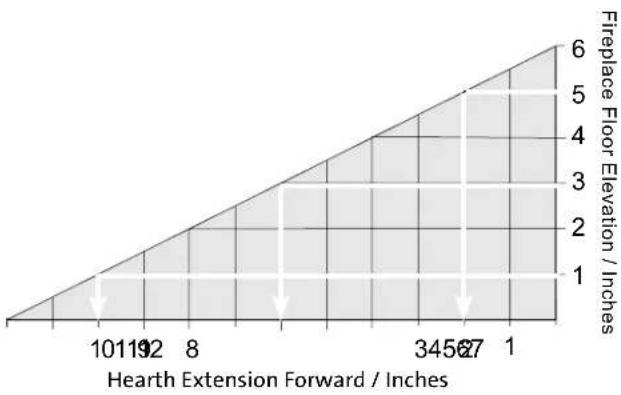
area
| Hearth Extension Forward / Inches | Fireplace Floor Elevation / Inches | |---|---| | 101192 | 1 | | 8 | 2 | | 345627 | 3 | | 1 | 4 | | 1 | 5 | | 1 | 6 |Figure 5.4. Hearth reduction slope.
5.4 Mantel and Ceiling Clearances
Measure clearances from the finished floor of the fireplace opening. See fig. 5.5.
Mantel Projection Clearance from Hearth
| A: 12” (30.5 cm) | 39 1/4” (99.7 cm) |
| B: 10” (25.4 cm) | 38 9/16” (97.9 cm) |
| C: 8” (20.3 cm) | 37 7/8” (96.2 cm) |
| D: 6” (15.2 cm) | 37 3/16” (94.5 cm) |
| E: 4” (10.2 cm) | 36 1/2” (92.7 cm) |
Minimum Ceiling Height from fireplace floor: 55 1/2" (141 cm)

Figure 5.5. Baseline Mantel and Trim clearance requirements.
6.0 Vent Guidelines
- All vent components must be installed in accordance with the terms of their listing and manufacturer's instructions. See the listing of approved vent manufacturers in the Appendix on page 44.
- The minimum height of termination cap from the top of the unit shall be no less than 10 ft.(3.05 m), and the maximum height shall be no more than 35 ft. (10.67 m). See figures 6.1 - 6.2.
- Steep roofs, nearby trees, or predominantly windy conditions can promote weak draft or occasional downdrafts. In such cases, increasing the height of the vent or installation of high wind termination caps may alleviate the condition.
- HORIZONTAL RUNS are not permitted anywhere in the venting system.
- Vent liners may be no less than 3 inches diameter nor greater than 3 inches diameter with the following exception:
PROPANE NOTICE: For LP installations with vent runs greater than 10', it is recommended that a 4" exhaust liner be used to ensure best operating performance.
This is especially appropriate for installations in warmer climates and intended for extended run times. Vent pipe adapters (3" to 4") are available from Jotul-approved venting manufacturers. When 4" Exhaust liner is used, it is recommended that the 3" Intake liner run all the way to vent terminus.
- Any unused flue or masonry enclosure can be used as a passageway for venting PROVIDED the flue is relined using 3" or 4" Listed Flexible Gas Liner.
- The remaining space around the liner in a masonry or factory-built flue CANNOT be used to vent any other appliance.
- Listed Flexible Gas Liners may not be exposed to any living space.
- Installation of any components not manufactured or approved by Jøtul or failure to meet all clearance requirements will void all warranties and could result in property damage, bodily injury, or loss of life.
- Never modify any venting component, or use any damaged venting product.
GAS VENT RULE
| ROOF SLOPE | Minimum HeightFrom Roof | |||
| Flat to 6/12 1'0" | 0.3M | |||
| Over 7/12 to 9/12 2'0" | 0.6M | |||
| Over 10/12 to 12/12 4'0" | 1.2M | |||
| Over 13/12 to 16/12 6'0" | 1.8M | |||
| Over 17/12 to 21/12 8'0" | 2.4M | |||
- THE GAS APPLIANCE AND VENT SYSTEM MUST BE VENTED DIRECTLY TO THE OUTSIDE OF THE BUILDING, AND NEVER ATTACHED TO A CHIMNEY SERVING A SOLID FUEL OR GAS BURNING APPLIANCE.
- The minimum vent height above the roof or adjacent walls is specified by building codes. A general guide to follow is the Gas Vent Rule below.
Vent Installation Procedure
This appliance must be vented through the chimney by a pair of 3 inch flexible aluminum liners listed for use with gas appliances. One duct is attached to the exhaust port on the top of the unit and will carry the exhaust gases to the outside of the house. This exhaust liner must run the full length of the chimney and be directly connected to the chimney termination cap. See figures 6.1 - 6.2.
The other 3 inch liner will be attached to the air intake port and will provide fresh air for combustion to the unit. This liner must extend through the damper area of the fireplace and at least into the first tile liner of the chimney. (U.S. ONLY). This liner can also extend the full length of the chimney and connect to the termination cap. SEE NOTICES BELOW. See also figures 6.1-6.2.
NOTICE
If the intake flex does not extend the full length of the chimney and connect to the unit and the termination cap - A NONCOMBUSTIBLE BLOCK OFF PLATE MUST BE CONSTRUCTED AND INSTALLED ABOVE THE UNIT BELOW THE END OF THE INTAKE DUCT (normally at the damper area). See figure 6.1.
To avoid cross venting the insert, label the duct to be used for the exhaust conduit at both the top and bottom ends. This ensures that the exhaust duct will be attached to the correct collar on the insert and on the chimney termination kit.
CANADA NOTE: Both Intake and Exhaust ducts must extend the full length of the chimney and be connected to both the unit and the termination kit.
NOTICE
THE USE OF AN EXISTING CHIMNEY AS AN AIR INTAKE IS NOT COVERED UNDER THE ANSI Z21.88-2014-CSA 2.33-M04 TEST METHODS AND RESULTING ITS/WHI PRODUCT CERTIFICATION. THE CODE AUTHORITY HAVING JURISDICTION MUST BE CONSULTED PRIOR TO PROCEEDING WITH THIS INSTALLATION METHOD.
6.1 Masonry Fireplace
- Measure height of the chimney to fireplace opening. Determine if both the intake and exhaust will be extended to the top of the chimney. In Canada, both liners must extend the full length of the chimney and be connected to both the unit and the termination kit.
- Cut the appropriate lengths of flex duct for both the intake and exhaust. Label both ends of the Exhaust duct to ease identification inside the house.
- Follow the manufacturer's instructions to attach the ends of the duct(s) to the chimney termination kit as appropriate.
- Drop the liners down the chimney from the top and rest the termination kit atop the chimney.
- Seal the chimney termination kit to the top of the chimney flue with high temperature sealant.
- Secure the appropriate direct vent cap to the termination kit.
- Inside the fireplace, fully extend the duct and trim any excess so that the ends hang approximately 15" from the floor of the fireplace.
- If the Intake duct is not attached to the chimney termination kit:
A. Install a length of flex duct that extends at least into the first flue tile.
B. The fireplace chimney flue must be permanently sealed-off from the room.
C. A direct vent cap is required to allow fresh air into the chimney flue and ultimately into the intake duct to the insert.
D. Attach the Fireplace Conversion Notice to the back of the fireplace if appropriate.
- Remove the Vent Adaptor from the unit by pushing it to the rear. Connect both ducts to the appropriate collars.
- Position the insert without Backer Plate half-way inside the fireplace and start the Vent Adaptor onto the top of the firebox. As you face the front of the insert, the Intake collar is on the left and the Exhaust is on the right.
- Secure the ducts to the appropriate collars on the Vent Adaptor with sheet metal screws or duct clamps. No sealant is required. See Vent Connection instructions on page 13.
WARNING: FAILURE TO POSITION THE PARTS IN ACCORDANCE WITH THIS DIAGRAM OR FAILURE TO USE ONLY PARTS SPECIFICALLY APPROVED WITH THIS APPLIANCE MAY RESULT IN PROPERTY DAMAGE OR PERSONAL INJURY.
IMPORTANT NOTICE: INSTALLATION OF A HIGH-WIND TERMINATION CAP IS RECOMMENDED FOR ALL IPI APPLIANCES TO HELP INCREASE PERFORMANCE.
We Recommend:
• M&G Duravent - Use Wind Screen #46DVA-VWG.
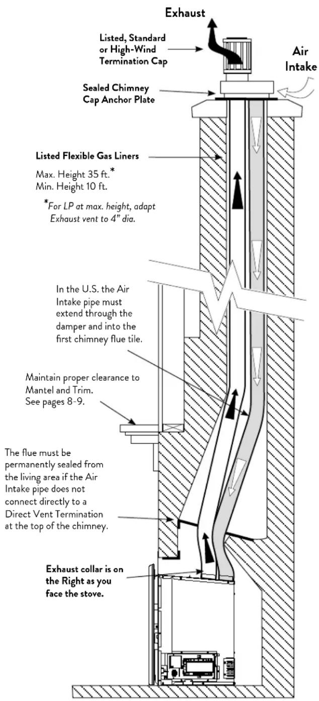
Figure 6.1. Masonry Fireplace Venting Configuration.
IN CANADA: Air intake must connect to chimney cap.
6.2 Factory-built Fireplace
IMPORTANT:
BEFORE STARTING THIS INSTALLATION, MAKE SURE THAT A GAS LINE CAN BE INSTALLED OR IS INSTALLED TO THE FIREBOX. THIS SHOULD ONLY BE DONE BY A QUALIFIED OR LICENSED PLUMBER OR GAS FITTER.
A factory-built fireplace will require modification prior to installation of the insert.
Modification
- Remove any factory-built glass doors, screen rails, screen mesh, fuel grates and other components attached to the firebox. Smoke shelves, shields, fuel grates and baffles may be removed if attached by mechanical fasteners. These should be kept for potential future re-installation. Do not cut out any sheet metal parts of the fireplace into which the insert will be installed.
If the factory-built fireplace has no gas access hole(s) provided, an access hole of 1 1/2" (37.5 mm) or less may be drilled trough the lower sides or bottom of the firebox in a proper workmanship-like manner. This access hole must be sealed with noncombustible insulation after the gas supply has been installed.
- Remove the damper assembly. This includes the damper blade, handle and any linkage. Two 3" liners must be able to pass through the damper area.
- Remove any fire screen or door assembly. This is usually accomplished with removal of a support rod on the inside of the fireplace frame.
- Remove the metal ash lip, if appropriate, to allow the insert to sit flat within the fireplace. Be sure to reinstall any screws removed.
- Attach the fireplace conversion notice to the back of the factory-built fireplace.
VENT NOTICE:
If the intake flex does not extend the full length of the chimney and connect to the unit and the termination cap - A METAL BLOCK OFF PLATE MUST BE CONSTRUCTED AND INSTALLED ABOVE THE UNIT BELOW THE END OF THE INTAKE DUCT (normally at the damper area). See fig. 6.2.
To avoid cross venting the insert, label the duct to be used for the exhaust conduit at both the top and bottom ends. This ensures that the exhaust duct will be attached to the correct collar on the insert and on the chimney termination kit.
CANADA NOTE: Both Intake and Exhaust ducts must extend the full length of the chimney and be connected to both the unit and the termination kit.
IMPORTANT NOTICE: INSTALLATION OF A HIGH-WIND TERMINATION CAP IS RECOMMENDED FOR ALL IPI APPLIANCES TO HELP MAINTAIN CONSISTENT PERFORMANCE.
We Recommend:
• M&G Duravent - Use Wind Screen #46DVA-VWG.

Figure 6.2. Venting through prefabricated fireplace chimney.
IMPORTANT NOTICE:
THE USE OF AN EXISTING CHIMNEY AS AN AIR INTAKE IS NOT COVERED UNDER THE ANSI Z21.88-1999-CSA 2.33-M04 TEST METHODS AND RESULTING ITS/WHI PRODUCT CERTIFICATION. THE CODE AUTHORITY HAVING JURISDICTION MUST BE CONSULTED PRIOR TO PROCEEDING WITH THIS INSTALLATION METHOD.
Prefabricated Fireplace Vent Procedure
- Measure height of the chimney to fireplace opening. Determine if both the intake and exhaust will be extended to the top of the chimney.
- Cut the appropriate lengths of flex for both the intake and exhaust.
- If the intake flex will be attached to the chimney termination kit: Attach the appropriate ends of the flex to the chimney termination kit.
CAUTION: AVOID CROSS-VENTING THE FLEX PIPE. Label the each end of the pipes (A & E) to assure proper identification and identification.
- Drop the liners down the chimney from the top and rest the termination kit atop the chimney.
- Seal the chimney termination kit to the top of the chimney pipe with high temperature sealant.
- Secure the appropriate DIRECT VENT CAP to the termination kit.
- Inside the fireplace, fully extend the flex duct and cut off any excess so that the liners extend approximately 15" from the floor of the fireplace.
- If the intake flex is NOT attached to the chimney termination kit: See VENT NOTICE on page 12.
A. It is necessary to install a minimum 6 foot length of flex pipe into the flue for the intake air.
B. A METAL damper block off plate must be constructed and installed in the damper area to completely seal off the flue from the room. Cut holes for both the intake and exhaust liners in the block off plate.
C. A direct vent cap is still required to allow fresh air into the chimney flue and ultimately into the intake flex and insert.
D. Attach the Fireplace Conversion Notice to the back of the fireplace if appropriate.
- Backer Plates or the Cast Iron Overlay panel must not block or seal any ventilation openings on the prefabricated fireplace.
WARNING: FAILURE TO POSITION THE PARTS IN ACCORDANCE WITH THESE DIAGRAMS OR FAILURE TO USE ONLY PARTS SPECIFICALLY APPROVED WITH THIS APPLIANCE MAY RESULT IN PROPERTY DAMAGE OR PERSONAL INJURY.
6.3 Vent Connection
Wear Safety Gloves!
Test fit the firebox in its final position to confirm it is level and plumb before connection to the vent system. A leveling bolt is located at each corner in the base of the firebox to allow a maximum 1/2" adjustment for hearth irregularities. Front bolts are accessible in each side compartment through the fireplace front. Tip the firebox forward to adjust the rear bolts out of the base.
- Refer to fig. 6.3. Remove the lock screw from the Vent Adaptor panel and disengage the panel from the firebox. Keep the screw for reinstallation.
- NOTE THE EXHAUST ID ON THE VENT PANEL. Attach the flex liners to the appropriate collars on the Vent Adaptor and secure each using sheet metal screws or duct clamps. Sealant is unnecessary.
- Position the firebox under the Adaptor panel and use the Latch Tool to engage the panel with the associated pins on the firebox Vent Manifold.
- Reinstall the Lock Screw to secure the adaptor panel to the firebox.
- Push the insert firebox fully into the final position. Do not install the Backer Plate or Overlay Frame until all other assembly and system checks are completed.
3" Listed Vent Liner
3" collar may be converted to 4" listed exhaust vent using manufacture's listed adaptor.

Figure 6.3. Vent Adaptor assembly.
3" to 4" OEM Vent Collar Adaptors:
ICC: TM-134
DuraVent: 3GVBTI4 P/N 810004525
7.0 Fireplace Assembly
Before beginning final assembly, push the insert into the fireplace and adjust the leveling bolts located at each corner as appropriate to achieve a level and plumb installation.
Complete the assembly procedures in this order:
- Gas Connection and Leak Test
- Gas Pressure Test
- Fuel Conversion
- High Altitude Adjustment
- Brick Panel or Reflective Glass Panel Kits
- Log Set
- Air Shutter Adjustment
NOTE: IN ORDER EASE ACCESS TO COMPONENTS, COMPLETE PROCEDURES 1-4 ABOVE BEFORE PLACING THE INSERT WITHIN THE FIREPLACE.
7.1 Gas Supply Connection
The gas supply line connection is made to the valve on the left side of the unit facing the front. The gas supply line should be a minimum of 3/8" in diameter, or the appropriate size to provide sufficient gas pressure to the valve regardless of the input setting. See fig. 7.1-7.2.
The GI 535 DV IPI is shipped with a 36" length of 3/8" flexible gas line to ease installation and service. However, for those areas where flexible gas lines are not permitted, use of a 3/8" iron nipple and union is recommended. See fig. 7.1.
The use of Flexible Gas Appliance Connectors is acceptable in many areas in the U.S., however, Canadian methods vary depending on local code.
ALL INSTALLATIONS MUST COMPLY WITH LOCAL CODE OR IN THE ABSENCE OF LOCAL CODE, MUST COMPLY WITH THE MOST RECENT EDITION OF THE NATIONAL FUEL GAS CODE ANSI Z223.1/NFPA 54 OR CAN-B149.
An integrated gas cock is built into the fuel supply line just upstream of the valve. This feature conforms to building codes requiring a shut-off valve be located within the same room as the appliance. The gas cock allows for the disconnection of the insert for servicing and maintenance. See figs. 7.2.
Secure all joints tightly using appropriate tools and sealing compounds (for propane units, be sure to use compounds that are propane resistant). Turn on gas supply and test for gas leaks using a soapy water solution or electronic gas sensor. Never use an open flame to check for leaks. Tighten or reconnect the leaking joint and retest for any gas leaks.
INSTALLATION OF A T-HANDLE GAS COCK IS REQUIRED IN MASSACHUSETTS IN COMPLIANCE WITH CODE 248 CMR.

Figure 7.1. External gas connection components.
7.2 Gas Pressure Test
Correct gas pressure is essential for efficient and safe operation of the gas insert. It is important that the correct pressure is established at the time of the installation.
The appliance must be isolated from the gas supply line by closing its internal manual gas shut-off valve (gas cock) during any pressure testing of the gas supply piping system that is equal to or exceeds pressures of 1/2 psig (3.5kPa).
- Use the Glass Frame Latch Tool to open and close the internal gas cock located on the supply line in the valve compartment. See fig. 7.3.
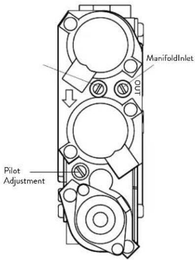
- Connect a manometer to the Inlet and Manifold test connection points located on the face of the Control Valve. See fig. 7.4. Adjust the pressure to the appropriate specifications indicated in the chart below.
INLET or supply pressure (the amount of gas coming to the valve.) Indicated by the arrow embossed on the valve.
OUT - for manifold pressure (the amount of gas that is coming out of the valve to the burner.)
REQUIRED INLET GAS PRESSURES (inches water column)
MIN MAX
NATURAL GAS 5.0 WC 7.0 WC
PROPANE 11.0 WC 14.0 WC
REQUIRED MANIFOLD PRESSURES
(inches water column)
MIN
MAX
NATURAL GAS 1.6 WC 3.5 WC
PROPANE 6.4 WC 10.0 WC
ALWAYS TEST PRESSURE WITH THE VALVE REGULATOR ADJUSTED TO THE HIGHEST SETTING.
Figure 7.2.
Insert the Latch Tool into the receiver hole in the gas cock.

Figure 7.3.
Pull the tool forward toward you to open the gas cock. Push it back to close the gas cock.

Store the Latch Tool in the valve compartment for future use.
Figure 7.4.
Pressure test points.
Symptoms of incorrect gas pressure include:
Insufficient gas pressure:
- Small pilot flame which can result in poor pilot rectification and/or frequent burner outages.
- Little variation in flame picture between HI and LO regulator settings.
• Insufficient gas to support more than one appliance causing nuisance outages or gas surges.
Excessive gas pressure:
- Permanent damage to valve causing complete appliance shut down.
- Too large a pilot flame resulting in overheating of the flame sensor and consequent shut down.
- Sooting due to impingement and/or incorrect fuel to air mix.
WARNING
DO NOT ALLOW THE INLET GAS PRESSURE TO EXCEED 14.0" WC (OR 1/2 PSIG) AS SERIOUS DAMAGE TO THE VALVE MAY RESULT.
7.3 Fuel Conversion
NOTE: IN ORDER TO ACCESS THE STEPPER MOTOR COMPONENTS, COMPLETE THE FUEL CONVERSION PROCEDURE BEFORE PLACING THE INSERT WITHIN THE FIREPLACE OR INSTALLING SURROUND PLATES.
The Jøtul GI 535 DV IPI is shipped from the factory equipped to burn Natural gas. Propane Fuel Conversion Kit 157784 is included with this appliance. Use Fuel Conversion Kit 157785 to convert back to Natural Gas. The kits contain all the necessary components, including labels that must be applied to the insert.
WARNING:
THE CONVERSION KIT IS TO BE INSTALLED BY AN AUTHORIZED SERVICE TECHNICIAN IN ACCORDANCE WITH THE MANUFACTURER'S INSTRUCTION AND ALL CODES AND REQUIREMENTS OF THE AUTHORITY HAVING JURISDICTION. FAILURE TO FOLLOW THESE INSTRUCTIONS COULD RESULT IN SERIOUS INJURY OR PROPERTY DAMAGE. THE QUALIFIED AGENCY PERFORMING THIS WORK ASSUMES RESPONSIBILITY FOR THIS CONVERSION.
IN CANADA:
THE CONVERSION SHALL BE CARRIED OUT IN ACCORDANCE WITH THE REQUIREMENTS OF THE PROVINCIAL AUTHORITIES HAVING JURISDICTION AND IN ACCORDANCE WITH THE REQUIREMENTS OF THE CAN1-B149.1 AND .2 INSTALLATION CODE.
LP Conversion Kit
Tools required:
- 1/2"or 13 mm open end wrench or deep-well socket
- Torx T20 driver
- 1/4" nut driver
- 7/16" open end wrench
LP Conversion Kit Contents:
• 1 Regulator Motor labeled for the appropriate fuel
• 2 Regulator Torx screws
• 1 Left Injector - 3/64" (Front Burner)
• 1 Right Injector - #56 (Rear Burner)
• 1, pilot Injector - BL .020 for NG - 226758 .013 for LPG - 226759
- Label A - to be completed and applied to the base of the valve compartment
- Label B - apply to the rating plate in the space indicated on the plate.
- Small valve label - apply to valve body
- Conversion instructions
SIT Proflame 885 Valve BTU/hr. Rating Specifications: NG LP
| Min. Input Rate, 0 - 2000 ft. | 11,500 | 11,000 |
| Max. Input Rate, 0 - 2000 ft. | 32,000 | 31,500 |
| Max. Input Rate, up to 4500 ft. | 31,000 | 30,500 |
See High Altitude specifications, Sect. 7.4, pg. 19.
CAUTION: WEAR SAFETY GLOVES WHILE WORKING WITHIN THE FIREBOX.
7.3.1 Fuel Conversion Procedure
- Turn off the gas supply and disconnect electrical power to the appliance.
- REMOVE THE GLASS FRAME using the Latch Tool. See fig. 1.1.
- RETRACT THE AIR SHUTTERS: Two Air Shutter cables are located on the floor in each side compartment - push them fully in. This action retracts the shutters and allows the burner to be disengaged from the firebox. See figs. 7.6, 7.8, and 8.1.
- REMOVE THE BURNER: Fig. 7.5
First lift out the two steel Support Shelves (A) located at each side of the burner. Grasp the burner assembly at the two large ports. Lift it straight up, tilting it back to disengage it from the injectors and front locator studs (B). Pull the assembly out of the firebox.

Figure 7.5. Burner removal.
- CHANGE THE BURNER INJECTORS: Use a 1/2" open end wrench or deep-well socket to remove the burner injectors from the brass fittings at the rear of the firebox. See fig. 7.6. Install the injectors from this conversion kit into the appropriate left and right locations and tighten securely.
6. CHANGE THE PILOT INJECTOR, Fig. 7.7
- Use the 7/16" wrench to remove the pilot head base. Use pliers to grip the pilot bracket to prevent misalignment.
- Remove the pilot injector from pilot base and replace with one in fuel conversion kit.
- Replace the pilot base and orient the hood to project flames to the Flame Sensor and burner carry-over ports. Retighten the pilot base nut.
Figure 7.6. Fuel Conversion Components.

7. LP CONVERSION ONLY: Remove the Upper Baffle Wing from the firebox. See fig. 7.8 below and also fig. 10.3.
- Remove three 10 mm hex nuts (A) from the front of the Upper Baffle plate.
- Loosen, but do not remove the two 10 mm hex nuts (B) from the rear of the Upper Baffle plate. These are not visible, but you will be able to locate them with your fingers. The baffle plate will drop down enough to enable you to remove the Inner Wing panel from the firebox.
- Remove the two sheet metal screws (C) that secure the Inner Baffle Wing to the center of the Upper Baffle.
- Replace the three front hex nuts on the Upper Baffle and re-tighten the rear nuts.

Figure 7.7 Replace pilot injector

Figure 7.8. Baffle Conversion - Propane Only.
Fuel Conversion Procedure, cont'd.
-
CHANGE THE VARIABLE REGULATOR TOWER on the gas control valve. See fig. 7.9.
-
Remove the heat shield from the valve compartment to access the Regulator Tower.
- Disconnect the IFC lead from the regulator lead.
- Remove the two Torx screws to remove the original regulator tower, rubber diaphragm and spring.
• Install the new regulator tower from the kit using the screws previously removed. Tighten screws securely. - Reconnect the Regulator lead to the IFC lead.
-
Replace the regulator heat shield.
-
Apply the conversion notice labels included in the kit to the appliance where they will be visible to any person who may be servicing the unit.
-
Label "A": Apply to the right side compartment adjacent to the Rating Plate.
- Label "B": Apply to the designated area on the Rating Plate
-
Small valve sticker: Apply to the valve body.
-
REINSTALL THE BURNER ASSEMBLY.
- CONFIRM AIR SHUTTER AND TRAY POSITIONS: Be certain that each air shutter on the underside of the burner is pushed fully forward (toward the front).
Also check that the shutter trays on the firebox floor, (fig 7.6, A) are pushed fully forward (toward the front).
- Tilt the burner assembly back as shown in fig 7.10 to engage it with the injectors in the back wall and the shutter trays on the firebox floor. Settle the assembly on the floor engaging the front retainer brackets (A) with the adjacent floor studs (B).
Properly positioned, the burner assembly will be level across the front and back and locked in place.
- Push/Pull each side air shutter cable to confirm that both shutters move freely through the full range of travel. See figs. 7.9, and 8.1, pg. 29.
-
Replace the two Side Panel Shelves, between the burner and the walls. fig. 7.5.
-
GAS LEAK CHECK: Use an electronic gas detector or soap solution to test for leaks at the pilot head and all gas line joints. NEVER USE AN OPEN FLAME TO CHECK FOR GAS LEAKS.
- PRESSURE TEST: Conduct a pressure test of the valve following the guidelines on pages 14-15 of this manual.
- BURNER CONFIRMATION: Follow Steps 1-5 under Initial System Check on page 29 before final assembly of accessory, log set, and surround components.
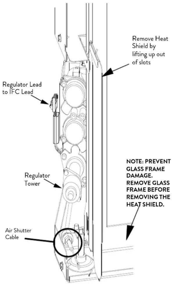
Figure 7.9. Replace the Regulator Tower.

Figure 7.10. Burner installation.
7.4 High Altitude Adjustment
When installing this appliance at altitude above 2000 feet, it is necessary to compensate for the thinner air (less volume of air per cubic foot). Higher altitudes affect the atmospheric pressure and heat value of gaseous fuels. The lower oxygen content in the air and the lower gas viscosity require the use of a different orifice to achieve efficient, clean combustion at the burner.
In the U.S.
THE DERATING KIT MUST BE INSTALLED BY AN AUTHORIZED SERVICE TECHNICIAN IN ACCORDANCE WITH THE MANUFACTURER'S INSTRUCTIONS AND ALL CODES AND REQUIREMENTS OF THE AUTHORITY HAVING JURISDICTION. THE INFORMATION STICKER MUST BE FILLED OUT BY THE INSTALLER AND APPLIED TO THE APPLIANCE AT THE TIME OF THE CONVERSION. THE QUALIFIED SERVICE AGENCY PERFORMING THIS WORK ASSUMES RESPONSIBILITY FOR THIS DERATING.
In Canada
This unit has been tested for installation at high altitudes in accordance with Canadian test standard CAN/CGA-2.17. THE DERATING SHALL BE CARRIED OUT IN ACCORDANCE WITH THE REQUIREMENTS OF THE PROVINCIAL AUTHORITIES HAVING JURISDICTION AND IN ACCORDANCE WITH THE REQUIREMENTS OF THE CAN1-B-149.1 AND .2 INSTALLATION CODE.
High Altitude Installations:
2000 ft. to 4500 ft. installations (or 610 m - 1370 m) See Table 1.
For high altitude installations consult the local gas distributor or the authority having jurisdiction for proper rating methods. If the installer must convert the unit to adjust for varying altitudes, the Conversion Notice label must be completed by the installer and applied to the appliance at the time of the conversion. See fig. 7.11.
Derating procedure
- Install the appropriate orifice as specified in the High Altitude Chart, Table 1 above.
- Follow the burner removal procedure detailed on page 16 of this manual.
- Use a 1/2" deep well socket or open end wrench to remove the orifices and replace with the appropriate ones from the high altitude adjustment kit.
- Attach the high altitude conversion sticker provided to the rating plate on the appliance. See figure 7.11.
- Follow the burner re-installation procedure detailed on page 18 and in Appendix Sect. 11.2 on page 44 of this manual.
6 It may be necessary to adjust the air shutters. See the Flame Picture / Air Shutter Adjustment on the page 30 for more details.

CAUTION: WEAR SAFETY GLOVES WHILE WORKING WITHIN THE FIREBOX.
| GAS | ORIFICE SIZE | ELEVATION | J∅TUL PART NO. |
| NATURAL GAS | #48 - Left#49 - Right | 2001' - 4500'(611 - 1170 m) | 129407 - Left129411 - Right |
| PROPANE | #56 - Left#57 - Right | 2001' - 4500'(611 - 1170 m) | 129466 - Left220977 - Right |
Table 1. High Altitude Orifice Chart.
THIS APPLIANCE HAS BEEN CONVERTED FOR USE AT AN ALTITUDE OF ____
Orifice Size: ____ Manifold Press: ____
Input, BTU/Hr: ____ Fuel Type: ____
Date of Conversion: ____ / ____ / ____
Figure 7.11 High Altitude Conversion Notice Label
7.5 Final Positioning
1. Clean the Fireplace.
Use a vacuum to thoroughly clean all debris from the firebox. This will eliminate the potential for the insert fans to blow dust and debris back into the room.
2. Blower Power Cord:
Extend the blower power cord out forward of the fireplace, routing it to the nearest power source.
The cord can extend approximately 8 feet (244 cm) to the right or 4 feet (122 cm) to the left.
The power cord can also be connected to a power source within the fireplace through a flexible steel conduit using Hardwire Kit 158043. Use the instructions included with that kit.
A compatible 10 foot extension cord is also available from your dealer, Jøtul PN 223253.
3. Backer Plate Options:
Follow the procedures for installation of the various backer plates detailed on pages 27-28.
7.6 Firebox Panel Installation
Use these instructions to install the panel kits below.
157877 Traditional Red
• Rear Panel - 225723
• Left Side Panel - 225724
• Right Side Panel - 225721
157878 Brownstone
• Rear Panel - 225893
• Left Side Panel - 225891
• Right Side Panel - 225892
158082 Fluted Panels
• Rear Panel - 226326
• Left Side Panel - 226325
• Right Side Panel - 226327
Tools Required
- Flat Head Screwdriver
• Pliers - Safety Glasses
! CAUTION !
THE PANELS ARE VERY FRAGILE. HANDLE GINGERLY, BEING CAREFUL TO AVOID CHIPPING THE EDGES OR CORNERS BY CONTACT WITH OTHER PARTS OF THE FIREPLACE.
- Check that each Panel Support Shelf, (A, Fig. 7.12) is centered against the side walls on the firebox floor. These are not used with the Fluted Panels and should be removed.
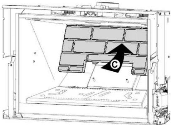
Use pliers to bend the Rear Panel support tabs (B) down, perpendicular to the rear wall. - Install the Rear Panel (C) up against the back wall, resting on the support tabs. Fig. 7.13.
- Slide each Side Panel (D) into position flat against the firebox side, resting the bottom edge on the support shelf or floor as appropriate. Fig. 7.14.
Locate the panel retainer tab at the top of the firebox (E) and use the screwdriver to bend it down just enough to secure the panel in place.

Fig. 7.12
natural_image
Technical diagram of a mechanical assembly with brick wall and mounting base, showing a black arrow labeled 'C' pointing to a component (no text or symbols beyond label)Fig. 7.13

Fig. 7.14
7.7 Install Optional Reflective Glass Panels
157879 Reflective Glass Kit
- Rear Panel - 225908
• Right Panel - 225909
• Left Panel - 225910
• Side Panel Shelf, (2) - 225929 - Cotton Gloves
Tools Required
Flat Head Screwdriver
Pliers
Safety Glasses
SKIN OIL IS DIFFICULT TO REMOVE FROM THE GLASS SURFACES. USE THE GLOVES PROVIDED TO PROTECT THE PANELS FROM FINGERPRINTS.
- Carefully unpack the panels and set each on carpet or other protective material. The panels will be installed with the textured surface facing against the firebox walls.
- Use pliers to bend the perforated tabs (A) to support the Rear Glass Panel as shown in fig. 7.15. Set the tabs at enough of an angle to keep the panel (B) lying back against the rear wall.
Place each Side Panel Shelf, (C) oriented as shown, on top of the steel spacer brackets between the burner and the side walls.
- Slide each Side Panel (D) into position flat against the firebox side, resting the bottom edge on the support shelf, fig. 7.16. Push each side panel back against the rear panel.
Locate the retainer tabs at the top of the firebox (E) and use the screwdriver to pry each down enough to secure the side panels in place.

DO NOT OVER-BEND THE TABS AS GLASS BREAKAGE COULD OCCUR. BEND TABS ONLY ENOUGH TO KEEP THE PANELS FROM FALLING FORWARD.

Fig. 7.15

Fig. 7.16
7.8 Traditional Log Set Installation
NOTE: Install the optional Brick Panels before installing the Log Set.
Install the log set in the order presented here.
Fig. 7.22 shows the final arrangement. Use the rock wool fibers from the Miscellaneous Hardware bag to simulate glowing embers.
Figure 7.17.
Traditional Log Set 157896
1 Rear Log 225880
2 Chunk Burner Log 225882
3 Left Lower Log 225881
4 Left Upper Cross Log 225884
5 Right Lower Log 225883
6 Right Upper Cross Log 225885

natural_image
Fossilized tree fragments labeled 1 to 6, showing detailed bark and root structures (no text or symbols beyond labels)
Figure 7.18. Engage the Rear Log with the two pegs located on rear burner skirt.

Figure 7.20. Engage the two pockets in the underside of Left Lower Log #3 with the two adjacent blocks on the burner base.
natural_image
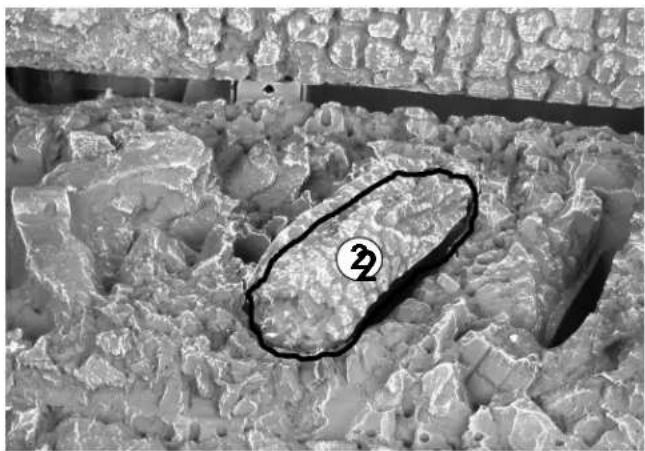
Microscopic view of a textured surface with a highlighted oval region containing a numbered marker (2), no readable text or symbols present.Figure 7.19. Place Small Center Log over the second large hole in the burner.

Figure 7. 21. Engage holes in the underside of #4 Left Upper Log with the pegs on Logs #1 and #3, resting on Log #2.
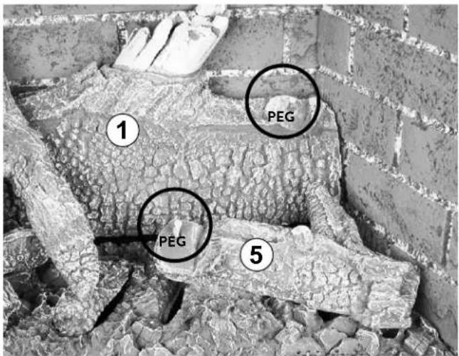
Figure 7.22. Engage pockets in the underside of Right Lower Log #5 with the adjacent blocks on the burner base.
natural_image
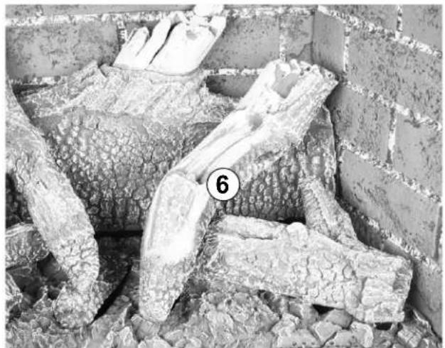
Close-up of cracked concrete blocks with visible cracks and a numbered label (6) in the corner (no text or symbols on the bricks themselves)Figure 7.23. Engage holes in the underside of the Upper Right Log #6 with the pegs on logs #1 and 5.

Figure 7.24. Traditional Log Set - complete assembly. Use the Rock Wool supplied and a toothbrush or tweezers to sparingly disburse small tufts of ember fibers across the front of the burner base.
DO NOT PLACE EMBER FIBERS AT THE REAR OF THE BURNER BASE. DO NOT OBSTRUCT BURNER PORTS.
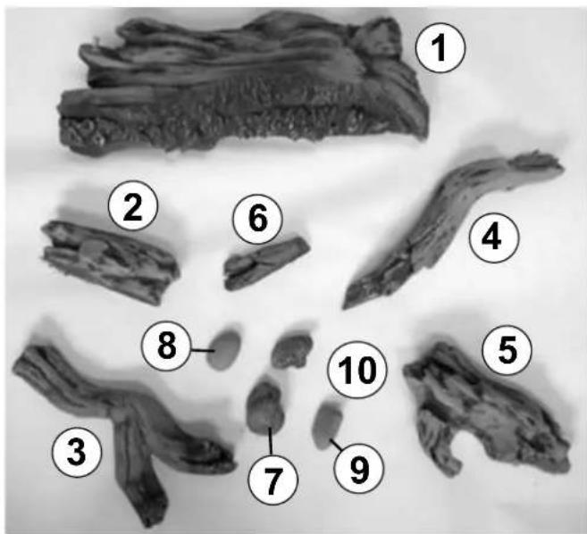
Beach Fire Log Set Installation
NOTE: Install the optional Brick Panels before installing the Log Set.
Install the log set in the order presented below.
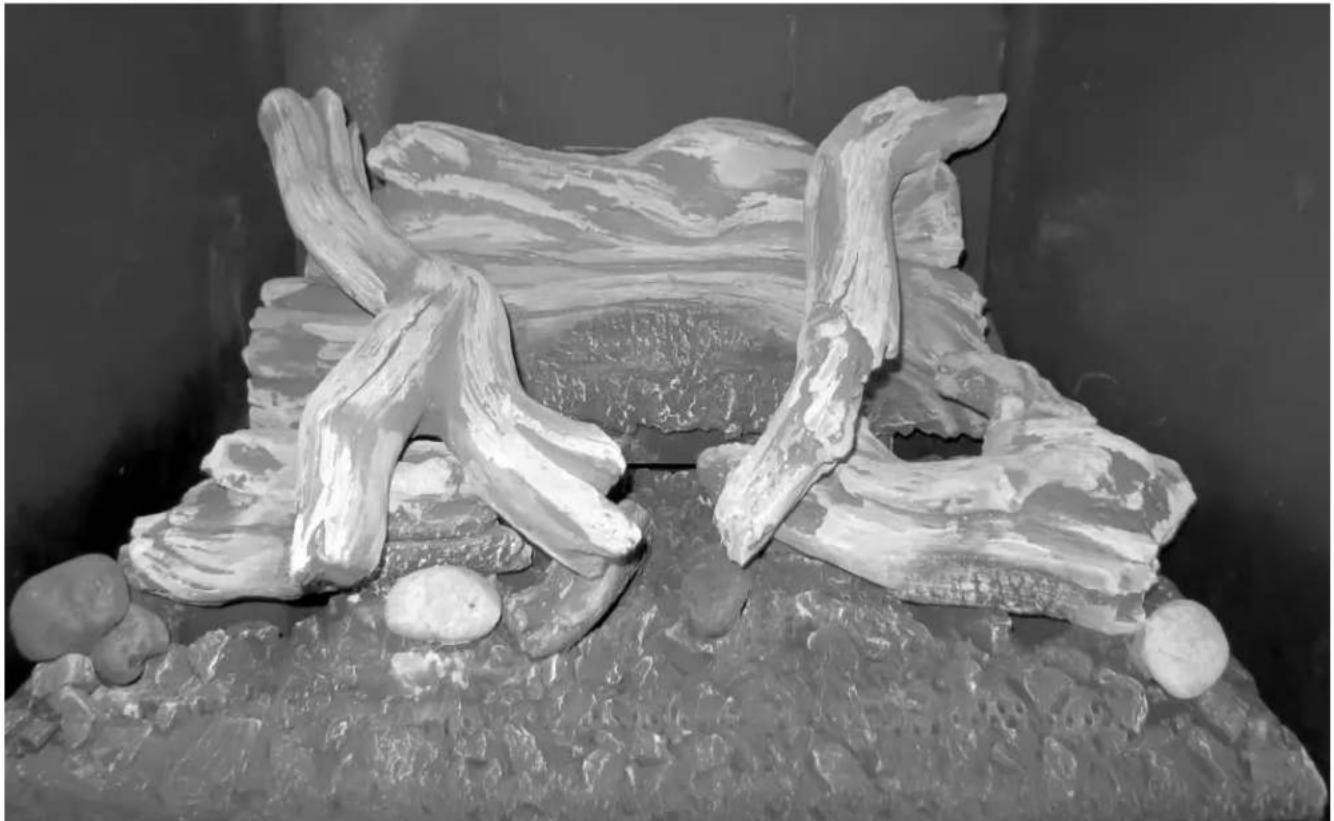
Fig. 7.25 shows the final arrangement.
GI 535 DV IPI Beach Fire Log Set 158093
| #1 Rear Log 226374 | |
| #2 Left Burner Log 226375 | |
| #3 Left Cross Log 226376 | |
| #4 Right Burner Log 226377 | |
| #5 Right Cross Log 226378 | |
| #6 Chunk Burner Log 226379 | |
| #7 Left Lower Rock 226384 | |
| #8 Middle Left Rock 226385 | |
| #9 Middle Right Rock 226386 | |
| #10 Right Lower Rock 226387 |
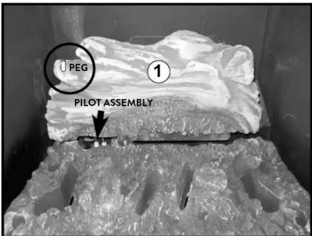
Figure 7.26. Engage the Rear Log with the two pegs located on rear burner skirt.

natural_image
Close-up of layered rock strata with a numbered marker (2) in the corner, no visible text or symbols.Figure 7.28. Engage the two pockets in the underside of Left Lower Log #2 with the two adjacent blocks on the burner base.

natural_image
Microscopic cross-section image showing layered material structure with a numbered region (6) and no visible text or symbols.Figure 7.27. Place Small Center Log #6 over the second large hole in the burner.

natural_image
Black-and-white photo of a textured rock formation with a numbered label (3) pointing to a specific structure, no readable text or symbols present.Figure 7.29. Engage holes in the underside of #3 Left Upper Log with the pegs on Logs #1 and indents on log #2, resting on log #2.

natural_image
Microscopic view of layered material structure with labeled region 4 (no text or symbols beyond label)Figure 7.30. Engage pockets in the underside of Right Lower Log #4 with the adjacent blocks on the burner base.
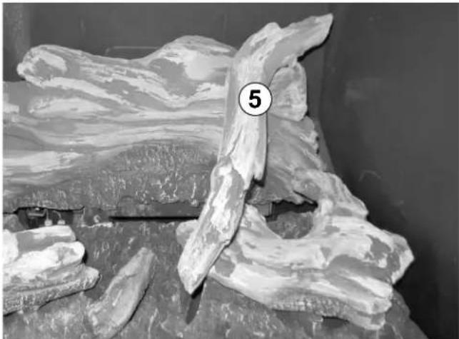
natural_image
Black-and-white photo of fossilized rock formations with a numbered label (5) in the corner, no readable text or symbols on the structures themselves.Figure 7.31. Engage indents in the underside of the Upper Right Log #5 with the matching marks on logs #1 and 4.
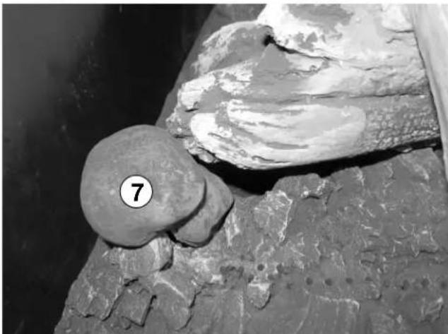
natural_image
Close-up of fossilized rocks and a circular object with a numbered label (7), no readable text or symbols present.Figure 7.32. Engage blocks in the underside of Right Lower Rock #1 with the adjacent pockets on the burner base by Log #2.
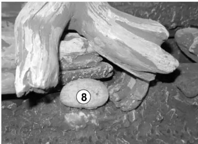
natural_image
Close-up of a stone and rock formation with visible texture and a numbered circle marker (8) in the center.Figure 7.33. Engage flat bottom on the underside of Middle Right Rock #2 with the adjacent pockets on the burner base by Log #2 and under log #3.

natural_image
Black-and-white photo of rocks and sediment with a numbered marker '9' on a textured surface (no readable text or symbols)Figure 7.34. Engage block on the underside of Middle Left Rock #3 with the adjacent pockets on the burner base at the meeting ends of Logs #4 and 5..

natural_image
Fossilized bone specimen displayed on a textured rock surface, with a circular marker labeled '10' in the corner (no readable text or symbols beyond the number)Figure 7.35. Engage blocks in the underside of Left Lower Rock #4 with the adjacent pockets on the burner base by Log #4.
natural_image
Black-and-white photo of a textured, abstract sculpture resembling a stylized animal or fossil, resting on rocks and stones (no text or symbols visible)Figure 7.36. Beach Fire Final assembly. Use a toothbrush or tweezers to lightly disburse small tufts of ember fibers across the front of the burner base.
DO NOT PLACE EMBER FIBERS AT THE REAR OF THE BURNER BASE. DO NOT OBSTRUCT BURNER PORTS.

WARNING: FREQUENTLY INSPECT THE PILOT AREA AND KEEP IT CLEAR OF MIS-PLACED LOGS OR DEBRIS. DO NOT ALLOW ANY MATERIAL TO OBSTRUCT PILOT CARRY-OVER PORTS.
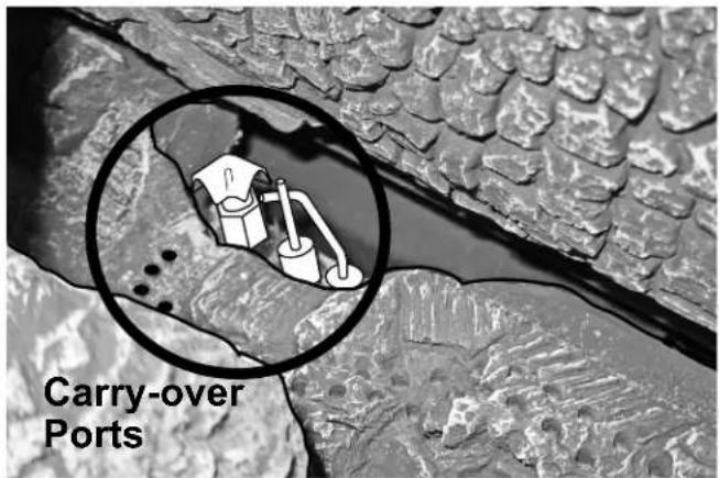
Figure 7.37. Pilot assembly location just below the Rear Log.
NOTE: COMPLETE FUEL CONVERSION, HIGH ALTITUDE ADJUSTMENT, AND BRICK OR GLASS PANEL INSTALLATION BEFORE ASSEMBLING BACKER PLATES.
7.9 Standard Backer Plate Installation
The standard Backer plates each incorporate hanger brackets to which the Cast Iron or Steel Surround Overlay Assembly will be attached. See page 4 for part numbers.
Tools Required
- phillips screwdriver
• safety glasses and gloves
Procedure
- Loosely attach the Backer Plate to the insert firebox using the ten, M6 x 8 phillip head screws as shown in Fig. 7.38. Tighten the screws in an alternating pattern.

natural_image
Technical line drawing of a rectangular frame with circular components and diagonal hatching, labeled Figure 7.38 (no text or symbols on the diagram itself)Figure 7.38. Backer Plate installation.
7.10 Three or Four-Sided Trimmable Backer Plate Installation
Tools Required
- zip wheel or other sheet metal cutting tool
- phillips screwdriver
• safety glasses and gloves
Trimmable Backer Plates include Hidden Hanger Bracket Kit 157888 which must be installed in order to attach the Cast Iron Overlay assembly.
An assistant will be helpful in aligning the backer panel with the hanger brackets and firebox.
Procedure
- Scribe and trim the 22 ga. sheet steel surround panel as appropriate for the fireplace face.
- Very loosely attach the Right, Left, and Top Hidden Surround Hanger Brackets to the outside of the insert firebox using the ten, M6 x 8 phillips head screws as shown in Fig. 7.39.
- Engage the backer plate panel inner flanges between the hanger bracket screws and the inner firebox shroud.
- Tighten the screws securely.
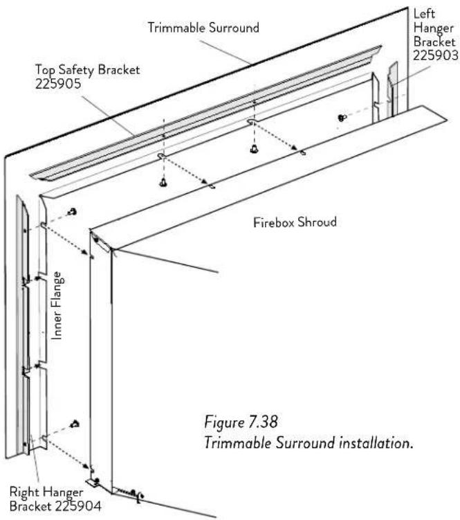
Figure 7.39 Trimmable Backer Plate installation.
7.11 Hidden Hanger Bracket Installation
The Hidden Hanger Brackets are used for installations that do not require the standard Backer Plate to overlap the fireplace opening. (They are also included with Trimmable Surround Kits.) The brackets provide a means of attachment for the Surround Overlay assembly.
Left Hanger Bracket 225903
Right Hanger Bracket 225904
Top Safety Bracket 225905
M6 x 8 phillips truss head screws, 10
- Attach each bracket using the 10 M6 x 8 phillips head screws provided, as shown in fig. 7.40.

natural_image
Technical line drawing of a rectangular device with internal components and mounting brackets (no text or symbols)Figure 7.40.
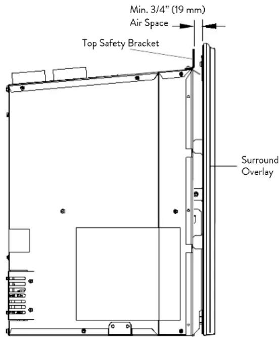
Figure 7.41.

NING! See Fig. 7.41 below.
- A MINIMUM 3/4"(19 mm) AIR SPACE MUST BE MAINTAINED BETWEEN THE SURROUND OVERLAY ASSEMBLY AND BACKER PLATE OR FIREPLACE FACE.
- DO NOT RECESS THE FIREBOX UNIT INTO THE FIREPLACE BEYOND THE FRONT LIP OF THE TOP SAFETY BRACKET.
- DO NOT MODIFY THE HANGER BRACKET POSITIONS OR REDUCE THE OVERLAY AIR SPACE IN ANY WAY. DOING SO MAY OVERHEAT THE APPLIANCE AND VOID THE WARRANTY.
7.12 Surround Overlay Assembly
Both the Cast Iron and the Steel Surround Overlays are shipped fully assembled, including the integrated Safety Barrier Screen.
- Remove and discard the four plastic joint shims from the front of the Brown Majolica frame assembly.
The other cast iron and steel overlay assemblies do not ship with joint shims.
Installation
The Cast Iron overlay assembly is heavy - assistance may be helpful. Handle the enameled assembly carefully to avoid inadvertent damage.
To install either type of surround overlay, simply engage the side mounting brackets with the steel support tabs on either the Hidden Hanger Brackets or Standard Backer Plate, whichever is appropriate to your installation.

Figure 7.42. Overlay assembly mounting brackets.
8.0 Operation
8.1 Initial System Check and General Operation
This appliance is designed to be operated with use of the Remote Control System. Run the following procedure to test basic burner function before completing the installation into the fireplace.
- Battery Installation: Install three 1.5v AAA batteries into the Remote Transmitter. The transmitter and receiver have already been synchronized at the factory. (If synchronization is lost, follow instructions on page 34.)
In the event of a power failure, install the four, 1.5v AA batteries into the IFC Back-up battery box in the right side firebox compartment. See Fig. 8.1. Do not leave them in the battery box permanently as the box will corrode. - Connect the appliance to 120 VAC house current.
- Initial System Purge: When lighting the appliance for the first time, or after a long period of disuse, it will take a few moments to clear the gas line of air. Once this purge is complete, the appliance will operate normally.
- Place the Burner Switch in the REMOTE position. With the transmitter OFF (dark display), press the Mode button to select the pilot mode. Press the UP/DOWN button to toggle between IPI and CPI modes. See descriptions on page 34. In CPI mode, the pilot will light immediately and remain lit. In IPI mode, the pilot will light before the main burner ignition and then enter the Smart Start ignition sequence as described on page 33.
PILOT ADJUSTMENT
Each pilot flame should be steady - not lifting or floating. The flames should be blue in color at the pilot hood, with traces of yellow toward the outer edges. It is important that the pilot flame fully engulf the top 1/4" of the flame rectifier / sensor. Both pilot flames should project one inch out of the pilot hood. See fig. 8.5, page 31. The pilot flames may be adjusted if necessary using the adjustment screw located on the gas valve body shown in fig. 7.4, page 15. Adjustments should be made only by a qualified gas technician.
- Set the Burner switch to REMOTE, and then press the transmitter Power button once to turn the burner ON. It will ignite at the Low setting.
See pages 34-36 for detailed Remote Control function instructions.
- For the first few hours of operation, it is common to detect some smoke and odor as the high-temperature paint cures. This condition is temporary and may be alleviated by opening windows and using a fan to circulate fresh air through the area.
- Condensation may develop on the glass upon each cold start. This "fog" will dissipate as the glass heats. The Smart Start ingition system is designed to minimize condensaton, however, that condition can be further reduced by operation in CPI mode.

WARNING:
READ AND UNDERSTAND ALL OPERATING INSTRUCTIONS BEFORE ATTEMPTING TO OPERATE THIS APPLIANCE. DO NOT ALLOW ANYONE TO OPERATE THIS APPLIANCE WHO HAS NOT READ AND UNDERSTOOD THESE INSTRUCTIONS. KEEP THE REMOTE CONTROL TRANSMITTER WHERE CHILDREN CANNOT REACH IT.

WARNING:
SEVERE INJURY. THIS APPLIANCE CAN BE SET TO OPERATE THERMOSTATICALLY. BE AWARE THAT THE APPLIANCE MAY BE VERY HOT EVEN WHEN THE BURNER IS NOT APPARENTLY OPERATING. KEEP CHILDREN AWAY FROM THE APPLIANCE.

WARNING:
OBSERVE CAUTION NEAR THE GLASS PANEL. THE GLASS MAY SHATTER IF STRUCK BY AN OBJECT. ALWAYS HANDLE THE GLASS PANEL WITH CARE. REMOVE GLASS ONLY FOR SERVICE.

Figure 8.1. Fireplace Control Switch / Battery Box location.
- IMPORTANT: It will be necessary to clean the glass after the first few fires. A white powdery residue will be evident which results from the curing of burner media. Use a non-abrasive household glass cleaner or warm water. IF THE GLASS IS NOT CLEANED, THIS RESIDUE CAN CAUSE THE GLASS TO BECOME PERMANENTLY ETCHED. DO NOT USE AMMONIA-BASED CLEANERS.
- Keep the control compartments free of dust and debris. Always keep the appliance area clear and free from combustible materials, or flammable liquids.
- This appliance can be operated with a continuously burning pilot flame. Exercise caution when using household products containing combustible vapors.
- CAUTION: DO NOT OPERATE THIS APPLIANCE WITH THE GLASS PANEL REMOVED, CRACKED OR BROKEN. REPLACEMENT OF THE GLASS SHOULD BE DONE BY A LICENSED OR QUALIFIED SERVICE PERSON. USE ONLY REPLACEMENT GLASS PROVIDED BY YOUR AUTHORIZED J∅TUL DEALER. NEVER SUBSTITUTE ANY OTHER TYPE OF GLASS.
8.1.1 Flame Picture / Air Shutter Adjustment
WARNING:
AIR SHUTTER ADJUSTMENTS SHOULD ONLY BE PERFORMED BY A QUALIFIED PROFESSIONAL SERVICE TECHNICIAN.
The volume of air supplied to the front and rear burners is regulated by individual air shutters which are controlled in turn by cables located at the each side of the firebox. The left cable controls the Front Burner and the right cable controls the Rear Burner. See figs. 8.1 - 8.2.
- PUSH the cable IN to OPEN the air shutter and increase air volume.
• PULL the cable OUT to decrease air volume.
The air shutter adjustment allows you to achieve the desired flame appearance. Generally, flame appearance is a matter of personal preference, however most people enjoy warm, yellowish flames of medium proportions. The simple air shutter adjustment feature allows you to dial-in the burners to acquire a flame picture “sweet spot” that combines efficient combustion with pleasing aesthetics.
NO SMOKE OR SOOT SHOULD BE PRESENT. CHECK LOG PLACEMENT IF ANY SOOT OR SMOKE IS APPARENT. IF SOOT OR SMOKE PERSIST, THE AIR SHUTTER MAY REQUIRE ADJUSTMENT TO ALLOW MORE AIR TO SUPPORT EFFICIENT COMBUSTION.

Figure 8.2. Front Burner Air Shutter Cable location - Left-side Compartment.

natural_image
Black-and-white illustration of a fire pit with stylized flame patterns and wood shavings (no text or symbols)Figure 8.3. Correct flame picture.
8.1.2 Adjusting Air Supply Settings
On first firing, push each Air Shutter cable in to fully open the air shutters. Place the Mode Control to ON and operate both burners set on HIGH for a minimum of 15 - 20 minutes to allow the insert components to come up to stable operating temperature.
The burners are very sensitive to air supply volume. Make air adjustments in 1/8" - 1/4" increments, waiting a few minutes to observe the flame pattern changes before making subsequent adjustments. Repeat the process until a satisfactory flame picture is achieved. Fig. 8.3.
Insufficient combustion air will promote inefficient combustion resulting in very long yellow flames and soot. Sooting produces black deposits on the logs, on the firebox walls, and potentially on the termination cap.
Very blue, transparent, or weak "anemic" flames are indications of too much air which, although efficient, are not very attractive.
Generally, Propane will require a more open air shutter setting than will Natural Gas.
8.2 Fireplace Operation
8.2.1 Burner Switch
- ON: Power is available to the Burner(s) only. They will ignite at the last previous flame level setting.
- REMOTE: Power is available for all appliance features.
• OFF: The Burner will not operate.
8.2.2 Pilot Modes
• Continuous Pilot Ignition (CPI)
This permits the pilot to continue burning for up to seven (7) days. If there is no call for heat within that period, the pilot will automatically extinguish and the appliance will default IPI mode in which the pilot will light at the next call for heat. This feature allows the burner to function properly under a variety of adverse conditions. For example, it can sometimes be difficult to establish positive draft through a very long vent system, particularly in very cold weather. CPI mode will also reduce glass condensation upon start-up.
Exercise caution when operating with a continuous pilot. DO NOT USE CLEANING PRODUCTS HAVING COMBUSTIBLE VAPORS AROUND THE OPERATING FIREPLACE.
• Intermittent Pilot Ignition (IPI)
This feature improves efficiency by shutting off the pilot flame when there is no call for heat. Ideal for use with thermostatic or manual remote control, the Integrated Fireplace Control (IFC) module ignites the pilot flame only when there is a call for heat. A battery back-up permits continued functionality in the event of a power failure.
See pages 28-29 for detailed information about the Smart Start Ignition System. In IPI mode, this feature automatically triggers a sequence of ignition trials that provide for consistent burner performance under a variety of installation and environmental conditions.
Although this process is intended to minimize draft instability, those issues can still be problematic. In such cases, the entire system will benefit from operation in CPI mode as the heat generated by a continuous pilot flame will help maintain a positive draft.
Pilot Flame Appearance
The pilot flames should be blueish-yellow in color and extend approximately 1" (25 mm) over to the burner ports and flame sensor. Each flame should be strong and steady - not fluttering or lifting. See fig. 8.5
8.2.3 Accent Lamp
The Accent Lamp is controlled by the hand-held remote transmitter. See figs. 8.23-8.24, page 36.
Heat generated from the accent lamp may also assist in maintaining draft in very long vent runs and thereby help ensure consistent IPI start-up performance.
LED Flash Codes
1 BLINK - Remote Command Reception
2 BLINKS - Low Battery
3 BLINKS - Lock Out
4 BLINKS - Burner Warm-up - Minimum Burn Rate

Figure 8.4. Fireplace Control switch.

Figure 8.5. Correct Pilot Flame Pattern.
8.2.4 Blower Function
An integral 120 cfm blower assists in moving heat into the living environment. Power is supplied through the same circuit used by the other fireplace components. The blowers must be electrically grounded in accordance with local codes, or, in the absence of local codes, with the current NFPA 70 - National Electrical Code or CSA C22.1 - Canadian Electrical Code.
The blower is controlled by the hand-held remote transmitter. See fan control figs. 8.21-8.22, page 36.
8.3 Proflame 2 Remote Control
8.3.1 Features Overview
The Proflame 2 Integrated Fireplace Control (IFC) module incorporates electronic remote control of the Jøtul GI 535 functions. Together with the hand-held transmitter, the IFC controls front and rear burner operation both manually and thermostatically. It will also control flame modulation, blower functions, and accent lighting.
The system utilizes an IPI system (Intermittent Pilot Ignition) and may also be switched to keep the pilot lit continuously for up to seven days, if desired (CPI - Continuous Pilot Ignition). Power is provided to the IFC by 120V house current and is backed-up by a 6V battery pack (four, 1.5v AA) for operation during a power failure.
Remote Control Transmitter
The hand-held remote transmitter has all controls available on its face for reliable, ease of use. It gives room temperature readout, set temperature readout, all function abilities as well as childproof lockout and low battery indicator. Icons appear on the screen indicating which mode of operation you are controlling. The four button controls are easy to learn and simple to operate. The transmitter is powered by 3, 1.5v AAA batteries.
Remote Control Receiver
The receiver is integrated with the IFC board which is located within the right side of the firebox.
Integrated Fireplace Control (IFC)
The IFC is the electrical heart of the fireplace operating system. It provides power to all components and converts to 6v DC in the event of power failure. The IFC also sends power to the fan system and the accent light, however, these features will not operate when no line power is available, The battery back-up only allows continued remote control of burner functions.
The red LED, located on the switch box, blinks in a series to indicate operation of various IFC functions as described on the following pages.
Sit 886 Modulating Valve
This valve has the ability to be stepped down in six increments between high and low. It can be done manually or by setting the remote control to the Smart thermostat modulation mode. Automatic modulation means that as the room temperature approaches the limit set for shut down, the valve gradually decreases or “steps-down” the fire intensity. Conversely, as room temperature cools, the valve gradually increases flame intensity. The overall result is more comfortable, even heating that minimizes temperature peaks and valleys.
Pilot Assembly
The pilot assembly consists of a pilot hood, electrode, and a flame sensor. When there is a call for heat, the electrode sends a spark to the pilot hood which ignites the gas. The sensor is then engulfed by the pilot flame and signals the gas valve to open when there is a call for heat.
- In CPI mode: The pilot will remain lit for up to 7 days after which it will automatically extinguish if there has been no call for heat during that time. The pilot will then re-ignite at the next call for heat.
- In IPI mode: The pilot will remain lit only while the burner is running. It will remain OFF until there is a new call for heat.
Smart Start Ignition System
This system is intended to provide consistent burner ignition under adverse draft conditions related to low outdoor temperature and/or challenging installation characteristics. Smart Start works by always lighting the burner at minimum rate (LOW) to develop sufficient draft necessary for steady, dependable remote operation.
This "warm-up" process encompasses two attempts to light the pilot and up to three attempts to light the burner before locking out. Burner Ignition:
The pilot electrode will spark for up to sixty (60) seconds to light the pilot flame. Burner ignition follows and remains at the minimum flame level for a 2 minute "warm-up" cycle, after which the system will release normal remote control functions to the operator. The LED indicator lamp will activate a series of 4 flashes every 5 seconds during the warm-up period.
If the pilot does not light within 60 seconds, a second attempt will be made after a 30 second purge period (no spark) to clear gas. The purge is followed by another spark cycle (up to 60 seconds) to light the pilot. Burner ignition follows within 4 seconds.
If the pilot still fails to light the second time, the system will Lock-out indicated by the LED flashing 3 times.
Burner Rectification Loss #1:
If the main burner ignites and then extinguishes, the system will automatically re-ignite the pilot for 4 seconds before lighting the burner. This time, the burner will remain in warm-up mode for just 15 seconds at minimum flame level before restoring remote control functionality.
Burner Rectification Loss #2:
The system will again light the pilot and then remain in pilot-only mode for a 2 minute warm-up with LED flashing 4 times. Burner ignition follows for another 2 minutes at minimum flame level, LED flashing 4, before restoring full flame adjustment. Blower and Lamp functions are available during warm-up.
Smart Start Ignition Sequence
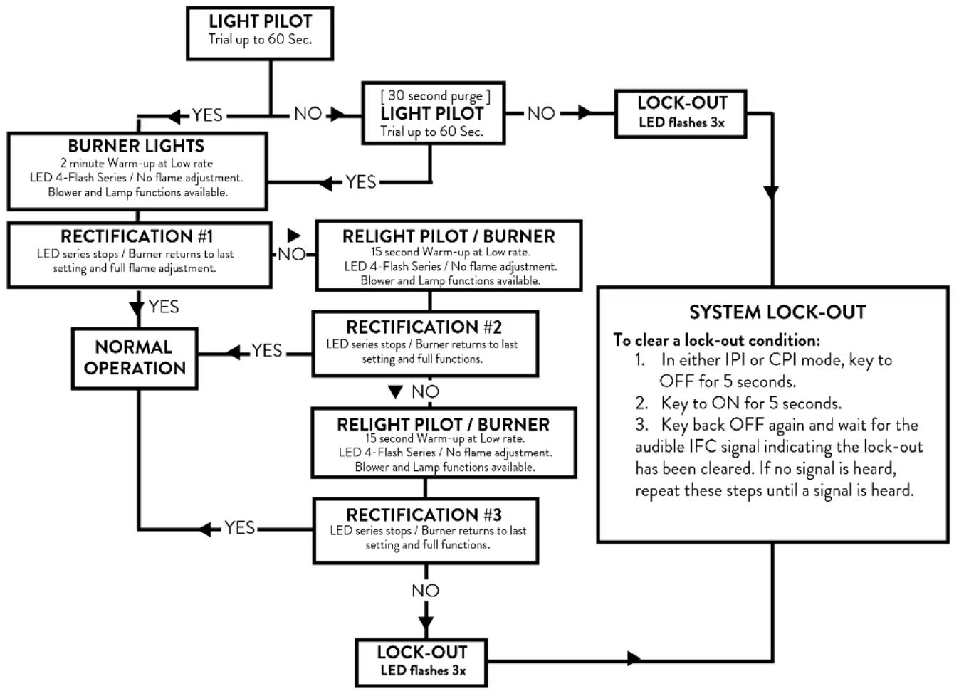
flowchart
graph TD
    A["LIGHT PILOT Trial up to 60 Sec."] -->|YES| B["BURNER LIGHTS 2 minute Warm-up at Low rate LED 4-Flash Series / No flame adjustment. Blower and Lamp functions available."]
    A -->|NO| C["30 second purge"] LIGHT PILOT Trial up to 60 Sec.]
    C -->|YES| D["RECTIFICATION #1 LED series stops / Burner returns to last setting and full flame adjustment."]
    C -->|NO| E["RELIGHT PILOT / BURNER 15 second Warm-up at Low rate. LED 4-Flash Series / No flame adjustment. Blower and Lamp functions available."]
    E --> F["NORMAL OPERATION"]
    F -->|YES| G["RECTIFICATION #2 LED series stops / Burner returns to last setting and full functions."]
    E -->|NO| H["RELIGHT PILOT / BURNER 15 second Warm-up at Low rate. LED 4-Flash Series / No flame adjustment. Blower and Lamp functions available."]
    H --> I["RECTIFICATION #3 LED series stops / Burner returns to last setting and full functions."]
    I -->|YES| J["LOCK-OUT LED flashes 3x"]
    I -->|NO| K["SYSTEM LOCK-OUT To clear a lock-out condition: In either IPI or CPI mode, key to OFF for 5 seconds. Key back OFF again and wait for the audible IFC signal indicating the lock-out has been cleared. If no signal is heard, repeat these steps until a signal is heard."]
    J --> L["LOCK-OUT LED flashes 3x"]
    K --> L
Burner Rectification Loss #3:
The system will again light the pilot and remain in pilot-only mode for another 2 minute warm-up with the LED flashing 4.Burner ignition follows for another 2 minute Warm-up at minimum flame level before restoring full flame adjustment. Blower and Lamp functions are available during warm-up.
The system will enter Lock-out if burner rectification is lost a third time.
INSTALLER / OPERATOR NOTE
Under certain conditions in which draft is unstable or weak, it is advisable to operate in Continuous Pilot mode (CPI). Warm weather, extreme cold weather, a long vent run, or high wind conditions are all contributing factors that can interfere with IPI functionality. A continuously running pilot can generate sufficient heat to help establish and maintain the draft strength required for rectification to occur.
WARNING:
OBSERVE CAUTION NEAR THE GLASS PANEL. THE GLASS MAY SHATTER IF STRUCK BY AN OBJECT. ALWAYS HANDLE THE GLASS PANEL WITH CARE.
ATTENTION:
BEFORE INSTALLATION OR MAINTENANCE, CLOSE THE SUPPLY GAS COCK, SET BURNER SWITCH "OFF", AND DISCONNECT POWER FROM THE FIREPLACE.
8.3.2 Remote Control Functions
Pilot Mode Control
The IPI/CPI functionality will be fully controlled by the remote transmitter. See Pilot Mode, page 30.
■ REMOTE - Set the fireplace burner switch to REMOTE to enable remote control burner operation.
■ OFF - Turns off burner functionality. Switch to OFF when the fireplace will not be used for an extended period of time.
■ ON - The fireplace pilot and burner will operate without remote control functionality.
Remote Transmitter
The Transmitter features a simple button layout and informative display screen. See figs. 8.6-8.7.
LCD DISPLAY - graphically indicates temperature settings and status of the Thermostat, Burner, Fan, and Accent Lamp.
ON / OFF Key - controls Burner, Fan, and Lamp functions.
THERMOSTAT Key - Used to set either Manual or Thermostatic Control and index through thermostatic functions.
UP / DOWN Arrow Key - Selects thermostat temperature range, fan speed, and flame height.
MODE Key - used to select the component to be controlled: CPI/IPI, Front Burner, Blowers, and Accent Lamp.
The included Wall Mount Bracket can be used for convenient Transmitter storage away from curious children.
IFC / Transmitter Mode Synchronization
- Install three fresh AAA batteries into the Transmitter.
- Set the fireplace Burner Switch to REMOTE.
- Press the black initialization button (PRG) at the lower right of the switch box faceplate (fig. 8.4, page 27). The board will "beep" three times signalling a 10-second synchronization time limit.
- Within the 10-second time frame, push the ON button on the Transmitter. The IFC will "beep" three times to indicate that it has acknowledged the transmitter command and sets to the particular code of that transmitter.
- After initialization, the burner switch should be left in the REMOTE position for normal operation.
For Manual Only functionality, hold the battery box initialization button (PRG) down until it "beeps" three or four times. Within 10 seconds, push the button again until it signals acknowledgement that the Remote function is off.
NOTE: In Manual functionality, there is no control over the blower, lamp, or pilot modes. The pilot defaults to CPI mode.
Figure 8.6.
Remote transmitter
function keys.


Figure 8.7. Remote transmitter display data.
8.3.3 Transmitter Key Control
Temperature Indication Display
■ With the transmitter in the OFF position, press the Thermostat Key and the Mode Key at the same time. The display screen will show the current room temperature cycling between Fahrenheit and Celsius indicators each time the keys are pressed simultaneously. See fig. 8.8.
Pilot Mode
With the transmitter in the OFF position, press the transmitter Mode key - IPI is the default mode. Press the UP arrow key to light the pilot and enter the 2-minute pilot Warm-up cycle. Fig. 8.9. When the pilot cycle is complete, the burner will ignite in at Low flame for an additional 2-minute cycle (LED flashing 4) before it will return to the last previous flame setting and accept further commands. Press the Up arrow to switch to the CPI icon to activate the Continuous Pilot Ignition mode. Fig. 8.10. Pressing the Down Arrow Key will return to Intermittent Pilot Ignition. A single "beep" will confirm reception of the command.
Turn on the Burner
Press the ON/OFF Key on the Transmitter. The display will show all the active icons. At the same time, the Receiver will activate the Pilot Ignitor. A single" beep" from the Receiver will confirm reception of the command.
Turn off the Burner
Press the ON/OFF Key. The display will show only the room temperature and icon. At the same time, the Receiver will deactivate the call for heat and the burner will shut down. Fig. 8.11. A single "beep" from the Receiver will confirm reception of the command.
Remote Burner Control
There are six flame levels available.
With the system ON, and the burner flame level at maximum, press the Down Arrow Key once to reduce the flame height by one step. Each time the Down Key is pressed, the flame will step down until the burner is finally turned off. Fig. 8.12.
The Up Arrow Key will increase the flame height each time it is pressed. If the Up Arrow Key is pressed while the system is On but the burner is Off, the flame will ignite in the Low [Level 1] position for a two-minute Warm-up cycle before it will respond to flame height adjustments. A single "beep" will confirm reception of the command and the red switchbox LED will flash in a series of 4 blinks for the duration of the cycle. See figs. 8.13-8.15.
When the Smart Start cycle is complete, the burner will automatically return to the previous set level.
The Burner is activated by using the Mode Key to select the Split Flow icon. Press the Up Arrow Key to turn it ON. Fig. 8.16. Press the Down Arrow Key to turn it OFF. A single "beep" will confirm reception of the command.

Fig. 8.8. Room temperature readings


Fig. 8.10. CPI ON.

Fig. 8.9. IPI is default.

Figure 8.11. Burner shut-down

Figure 8.12. Burner OFF.
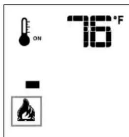
Fig. 8.13 Flame Level 1.
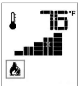
Fig. 8.14. Flame Level 5.

Figure 8.15. Flame Level 6.

Figure 8.16. Split Flame.
Room Thermostat (Transmitter Operation)
The Remote Control can operate as a room thermostat. The thermostat can be set to a desired temperature to control the comfort level in a room.
To activate this function, press the Thermostat Key. The display will indicate that the room thermostat is "ON" and the current Set Temperature is now displayed. Fig. 8.17.
To adjust the Set Temperature, press the Up or Down Arrow Keys until the desired Set Temperature is displayed. Fig. 8.18.
SMART Thermostat Function
This function adjusts the flame intensity according to the difference in the Set Point temperature and the actual room temperature. As the room temperature gets closer to the Set Point, the Smart Function will modulate flame intensity down.
To activate this function, press the Thermostat Key until the word "SMART" appears to the right of the thermometer bulb icon. Fig. 8.19.
To adjust the temperature, press the Up or Down Arrow Keys until the desired Set Temperature is displayed. Fig. 8.20.
Fan Control
Blower speed can be adjusted through six settings. To activate this function, press the Mode Key to index to the Fan Control icon and key to ON. See fig. 8.21.
Use the Up/Down Arrow Keys to turn ON, OFF, or adjust the fan speed. Fig. 8.22. A single “beep” will confirm reception of the command. After a 5 minute interval, the fan will power up to its highest speed and then modulate down to the established fan speed setting. The fan will continue to operate for 12 minutes after the burner is turned off. Manual speed control is not available when the SMART Thermostat is ON.
Accent Lamp Control
■ With the Remote ON, press the Mode Key to index to the Lamp icon. Figs. 8.23-8.24.
- Pressing the Up Arrow Key will turn the Lamp ON. Press the arrow keys to adjust the brightness.
- Pressing the Down Arrow Key will turn the Lamp OFF.
Child Safety Lock
This function will lockout the Transmitter to prevent unsupervised operation.
■ To activate the Lock, press the Mode key and UP Key at the same time. Fig. 8.25.
■ To de-activate the Lock, press the Mode Key and DOWN Key at the same time.

Fig. 8.17. Thermostat ON.
Room Temperature
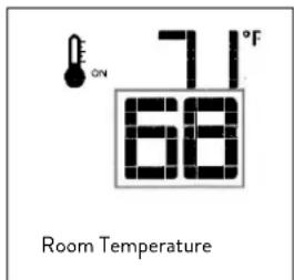
Fig. 8.18. Change Set Temperature.

Fig. 8.19. Smart Mode

Fig.8.20. Smart Set Temp.
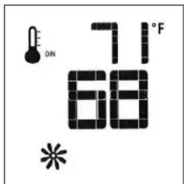
Fig. 8.21. Fan Mode.

Fig. 8.22. Fan Speed.

Fig. 8.23. Lamp Control.

Fig. 8.24. Lamp ON.

Fig. 8.25. Lock ON.

Fig. 8.26. Low Battery. Replacement. See page 33.
9.0 Maintenance

CAUTION: THE IGNITION SYSTEM OF THIS APPLIANCE CARRIES LIVE VOLTAGE. ALWAYS TURN OFF THE GAS SUPPLY TO THE FIREPLACE AND DISCONNECT THE POWER SOURCE BEFORE ANY SERVICE WORK IS PERFORMED, INCLUDING BATTERY REPLACEMENT.
With proper care and maintenance, your appliance will provide you with years of enjoyment. If you experience any problem with your fireplace insert, contact your Jøtul Authorized Dealer for assistance.
KEEP THIS MANUAL FOR REFERENCE AND MAKE IT AVAILABLE TO ANYONE USING OR SERVICING THE INSERT.
This appliance and venting system should be inspected before use and at least annually by a qualified service technician
9.1 General Cleaning
• Vacuum the controls area under the firebox at least monthly or more frequently if pet hair is in the environment. Always keep the appliance area clear and free from combustible materials, gasoline and other flammable liquids. ALWAYS BE SURE THE BURNER AND FIREBOX ARE COLD before using a vacuum cleaner.
- The firebox should be vacuumed annually. Inspect the pilot assembly for corrosion and have any damaged components replaced by a qualified service technician. Remove any debris from burner ports, particularly the pilot carry-over ports. See fig. 7.37, page 26. Use a brush attachment to vacuum the log set.
Gasket Inspection
- Inspect the glass gasket annually. Examine the gasket for signs of deterioration or stiffness and confirm that the gasket maintains a positive seal. This is important to prevent combustion gases escaping into the room. Replace the gasket if necessary. Refer to the replacement parts list on fig. 10.6, page 43.
9.2 Accent Lamp Replacement
- Remove the cast iron overlay assembly, backer plate, and glass frame.,
- Remove the bulb receptacle (two screws). See fig. 10.7, pg. 43. Replace with 222943 130V, 50W light bulb.
- Handle the new bulb with gloves. Skin oils will cause the bulb to fail prematurely. If you touch the bulb with your bare skin, wipe it clean with a soft cloth.
4, Replace components previously removed.
9.3 Battery Replacement
A Low Battery condition is indicated by an audible “double beep” signal when a command is transmitted from the hand held remote control.
- Disconnect electrical power from the appliance.
- Remove the cast iron overlay.
- The battery box located in the right side control compartment. Depress the cover plate tabs to open the box. Install four new AA batteries noting the polarity indicated on the front of the box.

CAUTION:
ELECTRICAL COMPONENTS SHOULD BE SERVICED ONLY BY A QUALIFIED TECHNITIAN. ALWAYS DISCONNECT ELECTRICAL POWER WHEN SERVICING THIS APPLIANCE.
LABEL ALL WIRES PRIOR TO DISCONNECTION WHEN SERVICING THE CONTROLS. WIRING ERRORS CAN CAUSE IMPROPER AND DANGEROUS OPERATION. ALWAYS VERIFY PROPER OPERATION AFTER SERVICING THE APPLIANCE.
9.4 Glass Care
Moisture condensation is a normal occurrence with gas appliances and particulate accumulation may appear on the inside surface to the glass. Use a dampened, soft cloth to clean the glass and polish with a dry, soft towel.
Specially-formulated ceramic glass cleaner may also be used.
⚠ DO NOT CLEAN GLASS WHEN IT IS HOT.
DO NOT USE ABRASIVE OR AMMONIA-BASED CLEANING SOLUTIONS. TAKE CARE TO NOT SCRATCH THE GLASS SURFACE.
Glass Replacement
To remove the glass panel or glass gasket:
- Use the Latch Tool to release the two glass frame latches on top of the firebox.
- Swing the top of the glass frame out and lift up to disengage it from the firebox.
- Lay the assembly on a flat surface and use a flat blade screwdriver or pliers to pry up the four steel tabs that secure the glass panel at the corners of the frame.
- Install the new glass panel and gasket in the glass frame and secure with the steel tabs. Do not over-tighten the tabs as that could break the glass.
ALWAYS USE J∅TUL AUTHORIZED PARTS. NEVER SUBSTITUTE ANY OTHER PARTS. See fig. 10.6, page 43.
WARNING:
OBSERVE CAUTION NEAR THE GLASS. THE GLASS PANEL MAY SHATTER IF STRUCK WITH AN OBJECT. ALWAYS HANDLE THE GLASS PANEL WITH CARE.
WARNING:
INSPECT THE GLASS SURFACE FOR SCRATCHES AS THESE CAN WEAKEN THE PANEL TENSILE STRENGTH. REPLACE THE PANEL IF ANY SCRATCHES ARE EVIDENT. USE ONLY JOTUL PN 157894. DO NOT USE ANY OTHER TYPE OF GLASS.
REPLACEMENT OF THE GLASS SHOULD BE DONE BY A LICENSED OR QUALIFIED SERVICE PERSON. USE ONLY REPLACEMENT GLASS PROVIDED BY YOUR AUTHORIZED J∅TUL DEALER. NEVER SUBSTITUTE ANY OTHER COMPONENTS.
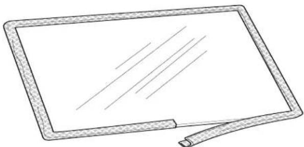
natural_image
Simple line drawing of a rectangular electronic device with a handle and screen (no text or symbols)Figure 9.1. Gasket application, PN 129124.

natural_image
Blank rectangular panel with diagonal lines and decorative border (no text or symbols)Figure 9.2. Glass Replacement. Bend tabs to secure panel. Use 220042 Tinnerman Clip to replace broken frame tabs.
10.0 Jøtul GI 535 DV IPI Replacement Parts
ONLY USE
REPLACEMENT PARTS
PROVIDED BY AN
AUTHORIZED
J∅TUL DEALER.

Figure 10.1 Controls components, right side compartment.
No. Part Number Description
| 1 225797 Controls, Skid Plate | |
| 2 117917 Screw, HWH SMA #8 x 1/2" SL Blk Oxide | |
| 3 225694 Latch Handle | |
| 4 157634 Proflame 2 IFC, Smart Start Board, replacement | |
| 158088 Proflame 2 IFC, Smart Start, Retrofit Kit * | |
| 5 118055 Kepnut, M4 Ext. Tooth Lock washer | |
| 6 117999 Screw, #8 x 3/8", SL SMA Type B, Zinc | |
| 7 225495 IFC Bracket | |
| 8 158006 Proflame 2 Battery Box | |
| 9 225497 IFC Heat Shield | |
| 10 225682 Ext. Wire Harness, Proflame 2, Split Flow | |
| 11 223951BKP Replacement Remote Wall Bracket / Blk PC | |
| 12 157492 Replacement Power Cord, 18 AWG - 10 ft. | |
| 13 157495 Replacement Multifunction Remote Transmitter | |
| 14. 157907 Replacement Battery Wire Harness - not illustrated | |
| 15. 226086 Vent Adaptor Assembly |
* for SN < 51001678 - kit includes Proflame 2 IFC, LED, Op. Manual

natural_image
Technical line drawing of a mechanical component with two circular features on a base plate (no text or symbols)
Figure 10.2. Valve Train components, left side compartment.
No. Part Number Description
| 1 226003 Flex Tube, Main Gas - 5/16" OD x 20" | |
| 2 129464 Compression Nut - 5/16" | |
| 3 129463 Compression Sleeve - 5/16" | |
| 4 129152 Jam Nut - Orifice Holder Assembly | |
| 5 220643 Orifice Holder, Straight | |
| 6 129407 Right Orifice, #48 NG | |
| 129466 Right Orifice, #56 mm, LP | |
| 7 225663 Retainer, Orifice Holder | |
| 8 117917 Screw, #8 x 1/2" HWH SMA Black Oxide | |
| 9 225840 Left Orifice, 1.95 mm, NG | |
| 129409 Left Orifice, 3/64", LP | |
| 10 129707 Flex Tube w/ Connectors - 3/8" OD x 36" | |
| 11 225526 Valve Bracket |
No. Part Number Description
| 12 | 225527 Valve Heat Shield | |
| 13 | 118214 | Screw, #8 x 1/4", Taptite, SLHWH, SZPL |
| 14 | 222922 | Valve, NG / 30% TD, Proflame w/ Stepper Motor |
| 15 | 157784 | Fuel Conversion Kit, Motorized / LP 30% TD |
| 16 | 157785 | Fuel Conversion Kit, Motorized / NG 30% TD |
| 17 | 222941 Elbow, Brass, Street, 90° 3/8" NTP | |
| 18 | 223214 | Nipple, Iron, 3/8" NTP x 1.5" Long |
| 19 | 129129 Elbow, 90° Brass, 3/8"NTP to 5/16" Dia. Compression | |
| 20 | 220044 | Adaptor, Brass, 3/8" NPT to 5/16" Dia. Compression |
| 21 | 157972 | Proflame Splitflow Solenoid Valve |
| 22 | 158200 | Shutoff Valve Kit |
| 24 | 223215 | Adaptor, Straight, Brass, 3/8" NTP x 3/8" Flare |
| 25 | 129390 Flex Tube, Main Gas - 5/16" OD x 14" | |
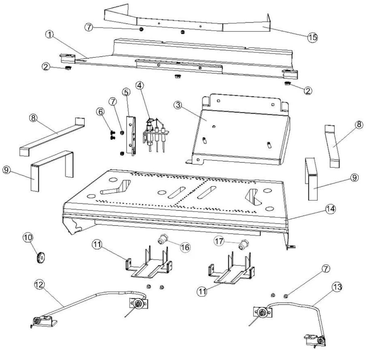
Figure 10.3 Internal firebox components.
No. Part Number Description
| 1 225706 Upper Baffle |
| 2 117968 Hex Nut, M6 Serrated Flange |
| 3 22571092 Rear Log Support |
| 4 158222 Pilot Assembly, NG, Ang Brkt, SS Body, 48” Wires, IPI |
| 5 225778 Pilot Bracket |
| 6 118279 Screw, Pan Head, Phillips, 10-32 x 1/4” |
| 7 117917 Screw, #8 x 1/2” HWH SMA |
| 8 22592992 Glass Shelf |
| 9 22592292 Brick Panel Shelf |
| 10 225525 Pilot Grommet, Silicone |
| 11 225970 Air Shutter Tray (Handle) |
| 12 157783 Left Shutter Cable Assembly |
| 13 157862 Right Shutter Cable Assembly |
| 14 157760 Burner Assembly, Replacement |
| 15 225847 Upper Baffle Wing Panel |
No. Part Number Description - not illustrated
| 16 | 225840 | Orifice, Left, 1.95 mm, 0 - 2000 ft. / NG |
| 129407 | Orifice, Left,#48, 2001 - 4500 V3 V3 ft. / NG | |
| 129409 | Orifice, Left, 3/64", 0-2000 ft. / LP | |
| 129466 | Orifice, Left,#56, 2001 - 4500 V3 V3 ft. / LP | |
| 17 | 129407 | Orifice, Right, #48, 0 - 2000 ft. / NG |
| 129411 | Orifice, Right, #49, 2001 - 4500 V3 V3 ft. / NG | |
| 129466 | Orifice, Right, #56, 0-2000 ft. / LP | |
| 220977 | Orifice, Right, #57, 2001 - 4500 V3 V3 ft. / LP |

Figure 10.4. Cast Iron Overlay and Steel Overlay Safety Screen Screen Assemblies
| No. | Part Number | Description |
| 1 | 10467892 | Replacement Overlay Frame, Top, MB |
| 157903 | Replacement Overlay Frame, Top, BRM | |
| 2 | 10467992 | Replacement Overlay Frame, Left, MB |
| 157904 | Replacement Overlay Frame, Left, BRM | |
| 3 | 10468092 | Replacement Overlay Frame, Right, MB |
| 157905 | Replacement Overlay Frame, Right, BRM | |
| 4 | 10468192 | Replacement Overlay Frame, Bottom, MB |
| 157906 | Replacement Overlay Frame, Bottom, BRM | |
| 5 | 225783 | Hanging Bracket (2) |
| 6 | 225785 | Adjustable Screen Retainer (3) |
| 225856 | Adjustable Screen Retainer, Enamel (3) | |
| 7 | 225937 | Top Corner Bracket, (2) |
| 225939 | Top Corner Bracket, Enamel | |
| 8 | 225784 | Top Screen Retainer |
| 9 | 117978 | Screw, M6 x 10 Button Head (29) |
| 10 | 225938 | Bottom Corner Bracket (2) |
| 225940 | Bottom Corner Bracket, Enamel (2) | |
| 11 | 225895 | Bottom Shade |
| 12 | 225782 | Bulkhead Screen Adjustor |
| 13 | 225731 | Safety Screen Assembly |
MB: Matte Black Paint
BRM: Brown Majolica Porcelain Enamel
| No. | Part Number | Steel Overlay Parts |
| 1 | 225986BKP | Replacement Steel Overlay, Black Powder Coat |
| 225986BZP | Replacement Steel Overlay, Bronze Powder Coat | |
| 225986JIP | Replacement Steel Overlay, Jotul Iron Paint | |
| 5 | 225989 | Steel Overlay Hanging Bracket |
| 225991 | Screen Retainer, Top | |
| 6 | 225992BKP | Adjustable Screen Retainer, Black Powder Coat |
| 225992BZP | Adjustable Screen Retainer, Bronze Powder Coat | |
| 225992JIP | Adjustable Screen Retainer, Jotul Iron Powder Coat | |
| 11 | 225990 | Steel Overlay Bottom Shade |
| 13 | 225731 | Screen, Quanex InvisiMesh. Cast Iron Overlay |
| 225985 | Screen, Quanex InvisiMesh. Steel Overlay |
Figure 10.5. Blower Assembly

No. Part Number Description
| 1 | 225846 | Blower Cover, GI 535 DV IPI |
| 2 | 117917 | Screw, HWH SMA #8 x 1/2 SL Blk Oxide |
| 3 | 225861 | Blower Chevron, GI 535 DV IPI |
| 4 | 225936 | Blower, Cross Flow, 12" Cage, 120 CFM |
| 5 | 225845 | Blower Bracket, GI 535 DV IPI |
| 6 | 118016 | Nut, Lock, M6, DIN 980V, Zinc - PIC |
| 7 | 117912 | Screw, HWH SMA #10 x 1/2 SL Zinc |
| 8 | 226722 | Gasket, Blower Mount, GI 535 |
Figure 10.7. Lamp Assembly

No. Part Number Description
| 1 225491 Light Fixture, Matte Black |
| 2 117917 Screw, HWH SMA #8 x 1/2" SL Blk Oxide |
| 3 222974 Glass, Ceramic, Light Fixture |
| 4 222977 Gasket, Light Fixture |
| 5 117967 Screw, Pan Head, SMA #7 x 3/8" |
| 6 157601 Replacement Holder Harness Connector |
| 7 222943 Light Bulb, 130V, 50 Watt |
Figure 10.6. Glass components.

No. Part Number Description
| 1 | 129124 Gasket, Fiber Glass w/ Graphite, .25" x 1.25 ", 7.3 ft. |
| 2 | 157894 Glass Panel w/ Gasket |
| 3 | 22570892 Glass Frame, Matte Black |
| 4 | 157895 Replacement Frame w/ Glass Assembly (inc. 1,2,3) |
| 5 | 220042 Tinnerman Glass Retainer Clip |
11.0 Appendix
11.1 Approved Vent Manufacturers
The Jøtul GI 635 DV IPI fireplace insert is approved for installation with listed 3-inch diameter flexible vent components supplied by the manufacturers listed below.
Use parts of one manufacturer only - DO NOT MIX VENT COMPONENTS FROM DIFFERENT MANUFACTURERS IN THE SAME SYSTEM.
MG DuraVent, Inc.
P.O. Box 1510
Vacaville, CA 95696-1510 800-835-4429
Selkirk Corporation
1301 W. President George Bush Hwy, Suite 330
Richardson, TX 75080-1139 800-992-8368
American Metal Products (Amerivent)
8601 Hacks Cross Rd.
Olive Branch, MS 38654 800-423-4270
Security Chimneys International Limited
2125 Monterey, Laval, Québec
Canada, H7L 3T6 450-973-9999
Metal-Fab, Inc.
P.O. Box 1138
Wichita, KS 67201 316-943-2351
Industrial Chimney Corp. (Excel Direct Vent)
400 J-F Kennedy
St. Jerome, (Quebec)
Canada, J7Y 4B7 450-565-6336
Bernard Dalsin Manufacturing Co. (Pro Form)
5205 208th Street West
Farmington, MN 55024 651-460-1080
Olympia Chimney Supply Inc. (Ventis)
600 Sanders Street Suite 2
Scranton, PA 18505-3400 570-496-8890
11.2 Reinstalling the Burner Assembly
Follow this procedure anytime the burner assembly has been removed from the firebox.
- CONFIRM AIR SHUTTER AND TRAY POSITIONS: Be certain that each air shutter on the underside of the burner is pushed fully forward (toward the front).
Also check that the shutter trays on the firebox floor, (fig 7.6, A) are pushed fully forward (toward the front).
- Tilt the burner assembly back as shown in fig 11.1 to engage it with the injectors in the back wall and the shutter trays on the firebox floor. Settle the assembly on the floor engaging the front retainer brackets (A) with the adjacent floor studs (B).
Properly positioned, the burner assembly will be level across the front and back and locked in place.
-
Push/Pull each side air shutter cable to confirm that both shutters move freely through the full range of travel. See figs. 7.9, pg. 18 and 8.1, pg. 29.
-
Replace the two Side Panel Shelves between the burner and the walls. See fig. 7.6, page 17.

Figure 11.1. Burner installation.
11.3 Proflame 2 Wiring Diagram

CAUTION:
ALWAYSDISCONNECTELECTRICALPOWERWHEN SERVICING THIS APPLIANCE.
LABEL ALL WIRES PRIOR TO DISCONNECTION WHEN SERVICING THE CONTROLS. WIRING ERRORS CAN CAUSE IMPROPER AND DANGEROUS OPERATION. ALWAYS VERIFY PROPER OPERATION AFTER SERVICING THE APPLIANCE.

11. 5 Jøtul GI 535 DV IPI Fireplace Insert Limited Warranty
Effective January 1, 2013.
This warranty policy applies to gas products identified by Jøtul trade names, as set forth below.
A. LIMITED FIVE YEAR WARRANTY - Cast Iron, Steel Doors, Surround Components, Firebox:
Jøtul North America Inc. (J∅TUL) warrants, to the original retail purchaser, that those components of the Jøtul Gas Stove or Fireplace Insert specified above will be free of defects in material and workmanship for a period of five (5) years from the date of purchase. This warranty is subject to the terms, exclusions and limitations set forth in the following text.
B. LIMITED TWO YEAR WARRANTY - Burner, Burner Treatments, Firebox Panels:
J∅TUL warrants, to the original retail purchaser, that those components of the Jøtul Stove or Fireplace Insert specified above will be free of defects in material and workmanship for a period of two (2) years from the date of purchase. This warranty is subject to the terms, exclusions, and limitations set forth in the following text.
C. LIMITED TWO YEAR WARRANTY - Enamel Finish:
J∅TUL warrants, to the original retail purchaser, the enamel finish on cast iron components of the Jøtul Stove or Fireplace Insert specified above against peeling or fading for a period of two (2) years from the date of purchase. This warranty is subject to the terms, exclusions and limitations set forth below.
D. LIMITED ONE YEAR WARRANTY - Gas & Electrical Components (controls, plumbing, valve, blower):
J∅TUL warrants, to the original retail purchaser, that those components of the Jøtul Gas Stove or Fireplace Insert specified above will be free of defects in material and workmanship for a period of one (1) year from the date of purchase. This warranty is subject to the terms, exclusions, and limitations set forth in the following text.
J∅TUL will repair or replace (including parts & labor), at its option, any of the above components determined by J∅TUL to be covered by this warranty. You must, at your own expense, arrange to deliver or ship the component to an authorized Jøtul dealer and arrange for pickup or delivery of the component after repairs have been made. If, upon inspection, J∅TUL determines that the component is covered by this warranty, the repair or replacement will be made as set forth above. This warranty is not transferable and is extended only to, and is solely for the benefit of, the original retail purchaser of the Jøtul Gas Stove or Fireplace Insert. This paragraph sets forth the sole remedy available under this warranty in the event of any defect in the Jøtul Gas Stove or Fireplace Insert.
The warranty period for any replaced component will be the remaining unexpired portion of the warranty period for the original component.
Please retain your dated sales receipt in your records as proof of purchase.
EXCLUSIONS AND LIMITATIONS
NOTICE: This warranty is void if installation or service is performed by someone other than an authorized installer, service agency or gas supplier, or if installation is not in conformance with the installation and operating instructions contained in this owner's manual or local and/or national fire and building regulations. A listing of local authorized installers, service agencies and gas suppliers can be obtained from the National Fireplace Institute at http://www.nficertified.org/.
This warranty does not cover the following:
1) Repair or replacement of parts that are subject to normal wear and tear during the warranty period or to parts that may require replacement in connection with normal maintenance. These parts include paint, lamp bulbs, gaskets, glass (except to the extent such parts suffer damage from thermal stress).
2) Damage due to incorrect installations not in conformance with the installation instructions contained in this owner's manual or local and/or national fire and building regulations.
3) Damage due to service performed by an installer, service agency or gas supplier, unless otherwise agreed to in writing by J∅TUL.
4) Labor or other costs associated with the repair of gas controls, plumbing, burners, log set, or sheet metal firebox beyond the warranty period.
5) Damage caused by unauthorized modification, use or repair.
6) Damage to enameled surfaces caused by improper operation or misuse, including use that is not in conformance with the operating instructions contained in this owner's manual. Such damage can typically be identified by bubbling, cracking, or discoloration of the enamel finish.
7) Costs incurred by travel time and/or loss of service.
8) Damage incurred while the Jøtul Gas Stove or Fireplace Insert is in transit.
IN NO EVENT SHALL J∅TUL, ITS PARENT COMPANY, SHAREHOLDERS, AFFILIATES, OFFICERS, EMPLOYEES, AGENTS OR REPRESENTATIVES BE LIABLE OR RESPONSIBLE TO YOU FOR ANY SPECIAL, INDIRECT, INCIDENTAL, CONSEQUENTIAL, PUNITIVE OR OTHER SIMILAR DAMAGES, INCLUDING, BUT NOT LIMITED TO, LOST PROFITS, LOST SALES, INJURY TO PERSON OR PROPERTY, OR DAMAGES TO A STRUCTURE OR ITS CONTENTS, ARISING UNDER ANY THEORY OF LAW WHATSOEVER. ALL IMPLIED WARRANTIES, INCLUDING THE IMPLIED WARRANTIES OF MERCHANTABILITY AND FITNESS FOR A PARTICULAR PURPOSE, OR OTHERWISE, ARE LIMITED IN DURATION TO THE LENGTH OF THIS WRITTEN WARRANTY. EXCEPT AS EXPRESSLY SET FORTH HEREIN, J∅TUL MAKES NO ORAL, WRITTEN OR OTHER WARRANTY WITH RESPECT TO J∅TUL GAS STOVES OR FIREPLACE INSERTS.
Some states do not allow the exclusion or limitation of incidental or consequential damages, or limitations on the length of implied warranties. Therefore, the above exclusions or limitations may not apply to you. This warranty gives you specific legal rights, and you may have other rights, which vary from state to state.
J∅TUL reserves the right to discontinue, modify or change the materials used to produce the Jøtul, Scan, or Atra Gas Stove or Fireplace. J∅TUL shall have the right to replace any defective component with substitute components determined by J∅TUL to be of substantially equal quality and price.
The dollar value of J∅TUL's liability for breach of this warranty shall be limited exclusively to the cost of furnishing a replacement component. J∅TUL shall not in any event be liable for the cost of labor expended by others in connection with any defective component. Any costs or expenses beyond those expressly assumed by J∅TUL under the terms of this warranty shall be the sole responsibility of the owner(s) of the Jøtul Gas Stove or Fireplace Insert. No dealer, distributor, or other person is authorized to modify, augment, or extend this limited warranty on behalf of J∅TUL. NO MODIFICATION OR CHANGE TO THIS WARRANTY WILL BE EFFECTIVE UNLESS IT IS MADE IN A WRITTEN DOCUMENT MANUALLY SIGNED BY AN AUTHORIZED OFFICER OF J∅TUL.
An authorized installer may have been provided with certain information related particularly to the Jøtul Gas Stove or Fireplace Insert; however, no authorized installer or other person who may service the appliance is an agent of J∅TUL. No inference should be made that J∅TUL has tested, certified, or otherwise pronounced any person as qualified to install or service the appliance. J∅TUL shall not be liable or otherwise responsible for any error or omission by a person installing or servicing a Jøtul Gas Stove or Fireplace Insert.
If you believe your Jøtul Gas Stove or Fireplace Insert is defective, you should contact your nearest authorized Jøtul dealer, who will process a warranty claim. IN ORDER TO QUALIFY FOR WARRANTY COVERAGE, J∅TUL MUST RECEIVE NOTICE OF A POSSIBLE DEFECT WITHIN SIXTY (60) DAYS OF THE DATE THE DEFECT IS FIRST DISCOVERED, OR REASONABLY COULD HAVE BEEN DISCOVERED.
This warranty is given by Jøtul North America, Inc., 55 Hutcherson Drive, Gorham, Maine 04038 USA
LIGHTING INSTRUCTIONS
FOR YOUR SAFETY, READ BEFORE LIGHTING.
WARNING:
IF YOU DO NOT FOLLOW THESE INSTRUCTIONS EXACTLY, A FIRE OR EXPLOSION MAY RESULT CAUSING PROPERTY DAMAGE, PERSONAL INJURY, OR LOSS OF LIFE.
A. This appliance is equipped with an ignition device which automatically lights the pilot. Do not try to light the pilot by hand.
B. BEFORE LIGHTING, smell all around the appliance area for gas. Be sure to smell next to the floor because some gas is heavier than air and will settle to the floor.
WHAT TO DO IF YOU SMELL GAS:
- Extinguish any open flame.
- Open windows.
- Do not light any appliance.
- Do not touch any electrical switches.
- Do not use any phone in your building.
- Immediately call your gas supplier from outside of the house.
- If your gas supplier cannot be reached, call the fire department.
C. Do not use this appliance if any part has been under water. Immediately call a qualified service technician to inspect the appliance and to replace any part of the control system and any gas control which has been under water.
LIGHTING INSTRUCTIONS
- STOP! Read the safety information above.
- Set the Burner Switch to the "OFF" position.
- NOTE: This appliance is equipped with an ignition device which automatically lights the pilot. Do not try to light the pilot by hand.
- Wait five (5) minutes to clear out any gas. Then smell for gas, including near the floor. If you smell gas, STOP! Follow "B" in the safety information above. If you do not smell gas, go to the next step.
- This appliance is intended to be operated by remote control. Set the Burner Switch to "REMOTE" to enable remote communication.
- With the Remote Transmitter OFF, press the Mode button then toggle UP/DOWN to CPI mode. The pilot will light.
- Press the Power button to light the burner.
- If the appliance will not operate, follow the instructions below "To Turn Off Gas To Appliance", and call your service technician or gas supplier.
- See the Owner's Manual for more detailed remote control instructions.
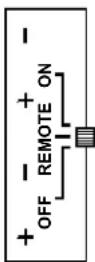
BURNER
SWITCH
REMOTE CONTROL KEYS

ON/OFF-
Press once, hear tone, backlight is ON. Press again, hear tone backlight is OFF.

THERMOSTAT - Press for 3 choices: ON: Manual thermostat control. OFF: Manual burner control. T-stat is OFF Smart: automatic burner modulation.

UP / DOWN - Press UP arrow or DOWN arrow to adjust thermostat, flame, fan, and lamp.

MODE - Press to cycle between CPI and IPI operation.
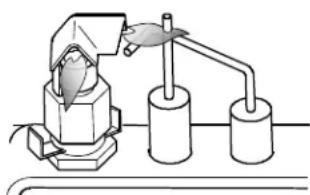
natural_image
Simple line drawing of a laboratory setup with a funnel, test tube, and two cylindrical containers (no text or symbols)Pilot Light Assembly
TO TURN OFF GAS TO THE APPLIANCE:
- Set the Remote thermostat to the lowest setting.
- Set the Burner Switch to the "OFF" position.
- Disconnect electric power to the appliance if service is to be performed.
CAUTION:
CAUTION: Do not operate this appliance with the glass removed, cracked or broken. Replacement of the glass panel shall be done by a licensed or qualified service person.
ATTENTION:
October 2021 139775.F
This appliance must be installed in conformance with local and national building regulations. Before beginning the installation, it is important that the these instructions be carefully read and understood. Jøtul maintains a policy of continuous product development. Consequently, products may differ in specification, color or type of accessories from those illustrated or described in various publications.

Your fireplace insert has a unique serial number stamped on the rating plate which is located in the right side compartment. Please record the serial number in the space below. You may also wish to attach your purchase receipt to this manual for future reference.
MODEL NAME: Jøtul GI 535 DV IPI Gas Fireplace Insert
SERIAL NUMBER:____
DATE OF PURCHASE:____
AUTHORIZED DEALER:____
ADDRESS ____
PHONE: ____
INSTALLER:____ DATE:____
FUEL TYPE:____
FUEL CONVERSION: NO ____ YES____
NOTES:____
Jotul North America, Inc.
55 Hutcherson Drive
Gorham, Maine 04038-2634
www.jotul.us
Jøtul ASA
P.O. Box 1411
N-1602 Fredrikstad
Norway
www.jotul.no
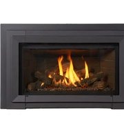


- Jøtul GI 535 DV IPI New Harbor
- Installation and Operation Instructions
- WARNING:
- ! DANGER
- Suggested Tools for Installation and Service
- INSTALLER NOTE:
- Table of Contents
- Unpacking the Fireplace Insert
- Jøtul GI 535 DV IPI (POD) Direct Vent Gas Fireplace Insert
- Specifications
- Input Rates:
- Natural Gas
- Propane
- Orifice Sizes:
- Test Standards
- Accessories
- Log Set Options
- Backer Plate Options
- Three-sided Backer Plate
- Three-sided Trimmable Backer Plate
- Four-sided Trimmable Backer Plate
- General Information
- IMPORTANT: SAVE THESE INSTRUCTIONS.
- INITIAL FIRING PROCESS - Heat-curing the Paint and Log Set
- We recommend you do the following BEFORE operating the appliance for the first time:
- Gas Appliance Curing Process
- DO NOT USE AMMONIA-BASED CLEANERS.
- Safety Information
- Electrical Hazards
- Power Requirement
- Leg Leveling Note:
- Installation
- Requirements
- Fireplace Requirements
- Minimum Fireplace Dimensions
- Maximum Fireplace Opening
- Cast Iron Overlay:
- Clearance Requirements
- Hearth Protection
- A: Hearth Protection Width:
- B: Hearth Protection Depth:
- C: Side Trim Clearance:
- D: Side Room Wall Clearance:
- E: Top Trim Clearance from hearth: 36 1/2" (92.7 cm)
- F: Mantel Clearance from hearth: See fig. 5.5.
- Mantel and Ceiling Clearances
- Vent Guidelines
- Vent Installation Procedure
- NOTICE
- Masonry Fireplace
- IMPORTANT NOTICE: INSTALLATION OF A HIGH-WIND TERMINATION CAP IS RECOMMENDED FOR ALL IPI APPLIANCES TO HELP INCREASE PERFORMANCE.
- Factory-built Fireplace
- IMPORTANT:
- Modification
- VENT NOTICE:
- IMPORTANT NOTICE: INSTALLATION OF A HIGH-WIND TERMINATION CAP IS RECOMMENDED FOR ALL IPI APPLIANCES TO HELP MAINTAIN CONSISTENT PERFORMANCE.
- IMPORTANT NOTICE:
- Prefabricated Fireplace Vent Procedure
- CAUTION: AVOID CROSS-VENTING THE FLEX PIPE. Label the each end of the pipes (A & E) to assure proper identification and identification.
- Vent Connection
- Wear Safety Gloves!
- Fireplace Assembly
- Gas Supply Connection
- Gas Pressure Test
- REQUIRED MANIFOLD PRESSURES
- ALWAYS TEST PRESSURE WITH THE VALVE REGULATOR ADJUSTED TO THE HIGHEST SETTING.
- Symptoms of incorrect gas pressure include:
- Insufficient gas pressure:
- Excessive gas pressure:
- WARNING
- Fuel Conversion
- IN CANADA:
- LP Conversion Kit
- Tools required:
- LP Conversion Kit Contents:
- CAUTION: WEAR SAFETY GLOVES WHILE WORKING WITHIN THE FIREBOX.
- Fuel Conversion Procedure
- CHANGE THE PILOT INJECTOR, Fig. 7.7
- LP CONVERSION ONLY: Remove the Upper Baffle Wing from the firebox. See fig. 7.8 below and also fig. 10.3.
- Fuel Conversion Procedure, cont'd.
- High Altitude Adjustment
- In the U.S.
- In Canada
- High Altitude Installations:
- Derating procedure
- Final Positioning
- Clean the Fireplace.
- Blower Power Cord:
- Backer Plate Options:
- Firebox Panel Installation
- Traditional Red
- Brownstone
- Fluted Panels
- Tools Required
- ! CAUTION !
- THE PANELS ARE VERY FRAGILE. HANDLE GINGERLY, BEING CAREFUL TO AVOID CHIPPING THE EDGES OR CORNERS BY CONTACT WITH OTHER PARTS OF THE FIREPLACE.
- Install Optional Reflective Glass Panels
- Reflective Glass Kit
- SKIN OIL IS DIFFICULT TO REMOVE FROM THE GLASS SURFACES. USE THE GLOVES PROVIDED TO PROTECT THE PANELS FROM FINGERPRINTS.
- Traditional Log Set Installation
- NOTE: Install the optional Brick Panels before installing the Log Set.
- Rear Log 225880
- Chunk Burner Log 225882
- Left Lower Log 225881
- Left Upper Cross Log 225884
- Right Lower Log 225883
- Right Upper Cross Log 225885
- Beach Fire Log Set Installation
- Standard Backer Plate Installation
- Procedure
- Three or Four-Sided Trimmable Backer Plate Installation
- Hidden Hanger Bracket Installation
- Surround Overlay Assembly
- Installation
- Operation
- Initial System Check and General Operation
- PILOT ADJUSTMENT
- Flame Picture / Air Shutter Adjustment
- AIR SHUTTER ADJUSTMENTS SHOULD ONLY BE PERFORMED BY A QUALIFIED PROFESSIONAL SERVICE TECHNICIAN.
- Adjusting Air Supply Settings
- Fireplace Operation
- Burner Switch
- Pilot Modes
- • Continuous Pilot Ignition (CPI)
- • Intermittent Pilot Ignition (IPI)
- Pilot Flame Appearance
- Accent Lamp
- LED Flash Codes
- Blower Function
- Proflame 2 Remote Control
- Features Overview
- Remote Control Transmitter
- Remote Control Receiver
- Integrated Fireplace Control (IFC)
- Sit 886 Modulating Valve
- Pilot Assembly
- Smart Start Ignition System
- Burner Rectification Loss #1:
- Burner Rectification Loss #2:
- Burner Rectification Loss #3:
- INSTALLER / OPERATOR NOTE
- ATTENTION:
- Remote Control Functions
- Pilot Mode Control
- Remote Transmitter
- IFC / Transmitter Mode Synchronization
- Transmitter Key Control
- Temperature Indication Display
- Pilot Mode
- Turn on the Burner
- Turn off the Burner
- Remote Burner Control
- Room Thermostat (Transmitter Operation)
- SMART Thermostat Function
- Fan Control
- Accent Lamp Control
- Child Safety Lock
- Maintenance
- KEEP THIS MANUAL FOR REFERENCE AND MAKE IT AVAILABLE TO ANYONE USING OR SERVICING THE INSERT.
- General Cleaning
- Gasket Inspection
- Accent Lamp Replacement
- Battery Replacement
- CAUTION:
- Glass Care
- Glass Replacement
- Jøtul GI 535 DV IPI Replacement Parts
- Appendix
- Approved Vent Manufacturers
- Reinstalling the Burner Assembly
- Proflame 2 Wiring Diagram
- 5 Jøtul GI 535 DV IPI Fireplace Insert Limited Warranty
- LIMITED FIVE YEAR WARRANTY - Cast Iron, Steel Doors, Surround Components, Firebox:
- LIMITED TWO YEAR WARRANTY - Burner, Burner Treatments, Firebox Panels:
- LIMITED TWO YEAR WARRANTY - Enamel Finish:
- LIMITED ONE YEAR WARRANTY - Gas & Electrical Components (controls, plumbing, valve, blower):
- EXCLUSIONS AND LIMITATIONS
- LIGHTING INSTRUCTIONS
- FOR YOUR SAFETY, READ BEFORE LIGHTING.
- WHAT TO DO IF YOU SMELL GAS:
- REMOTE CONTROL KEYS
- TO TURN OFF GAS TO THE APPLIANCE:
Brand : JOTUL
Model : GI 535 DV IPI
Category : Fireplace