CF56DC4RL - Household Fan Khind - Free user manual and instructions
Find the device manual for free CF56DC4RL Khind in PDF.


User questions about CF56DC4RL Khind
0 question about this device. Answer the ones you know or ask your own.
Ask a new question about this device
Download the instructions for your Household Fan in PDF format for free! Find your manual CF56DC4RL - Khind and take your electronic device back in hand. On this page are published all the documents necessary for the use of your device. CF56DC4RL by Khind.
USER MANUAL CF56DC4RL Khind
USER MANUAL
SERIAL NO.:
KHIND®
Experience More
CEILING FAN
CF56DC3RL
CF56DC4RL
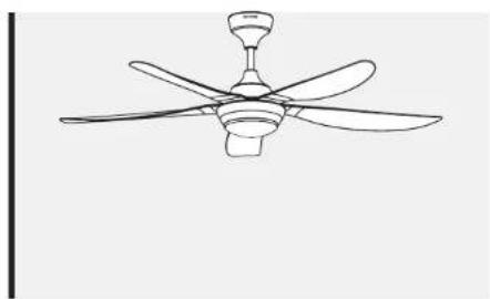
natural_image
Line drawing of a five-bladed ceiling fan with propeller blades (no text or symbols)KHIND CARE Mobile App

Mobile App

Download to register for
E-warranty & enjoy hassle-free after-sales services
1-800-88-0032
khind.com.my
IMPORTANT
Please read this manual carefully before operating this product. Keep this manual handy for further reference,
P/N: 40-51795-00
1

Safety Precaution Information
Safety & Warning Information
- This appliance must be earthed.
- Do not use any other down rod except provided by KHIND. This is to ensure good performance and extra protection.
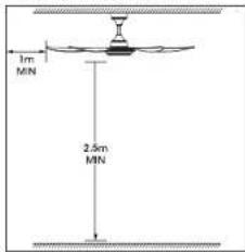
- To reduce the risk of injury to person, install fan at least 2.5m (8.3ft) above the ground and 1 meter from the nearest wall.
- Ensure Pipe has been fully tightened to the MOTOR Shaft. (Bolt tightening torque is 800\~1000 N·cm) Can cause injury if ceiling fan drops.
- The Cotter Pin must be fixed into the hole of the bolt and bent to secure the nut from loosening. It can cause injury if Ceiling Fan drops.

-
The mounting and replacement of parts of the safety suspension system and LED light kit shall be performed by the manufacturer, its service agent or suitably qualified persons.
-
The double pole single throw switch must have a contact separation of at least 3mm. It must be incorporated in the fixed wiring.
-
Safety wire and mounting hook must be able to withstand 10 times the weight of fan body. (Net weight - CF56DC3RL & CF56DC4RL: 4.9kg)
-
Disconnect power supply before dismantling any part for cleaning.
-
Do not attempt to repair fan. Always return fan to our authorised service agent for repair.
-
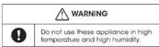
Do not use in hot or wet environment or near to flammable materials.
-
The wires in this main leads are coloured in accordance with the following code:
Green/Yellow - Earth
Brown - Live
Blue - Neutral
-
If the supply cord is damaged, it must be replaced by the manufacturer, its service agent or similarly qualified persons in order to avoid a hazard.
-
This appliance is not intended for use by persons (including children) with reduced physical, sensory or mental capabilities, or lack of experience and knowledge, unless they have been given supervision or instruction concerning use of the appliance by a person responsible for their safety. Children should be supervised to ensure that they do not play with appliance.
-
Primary suspension system length more than 300mm of non-standard down rod shall be supplied by the same manufacturer, with similar material, complete with safety wire rope, marking and installation instruction.
-
If unusual oscillating movement is observed, immediately stop using the ceiling fan and contact the manufacturer, its service agent or suitably qualified persons.
-
Primary suspension system length more than 300mm of non-standard down rod shall be supplied by the same manufacturer, with similar material, complete with safety wire rope, marking and installation instruction.
- If unusual oscillating movement is observed, immediately stop using the ceiling fan and contact the manufacturer, its service agent or suitably qualified persons.
Cleaning & Maintenance
- Keep the fan clean.
- Use it in dry place.
- Do not bend the blades when installing & maintaining
- Wipe away dirt with clean soft cloth, soap & water to clean the fan. Wipe until dry Do not use solvents such as gasoline or petroleum.
- It is recommended to examine the fan suspension system for wear & tear of the bolt & rod at least once every year.
Parts Identification
- Down Rod Kit
2 Remote Control & Receiver - Top Canopy
- R Cotter Pin
- M6x38 Hexagon Bolts
- ∅6 Flat Gasket
- ∅6 Spring Washer
- M6 Hex Nuts
- Down Rod Sleeve
- Self-tapping Screw
- Round Cap Screws
- Fan Blade
- LED Light
- LED Light Cover
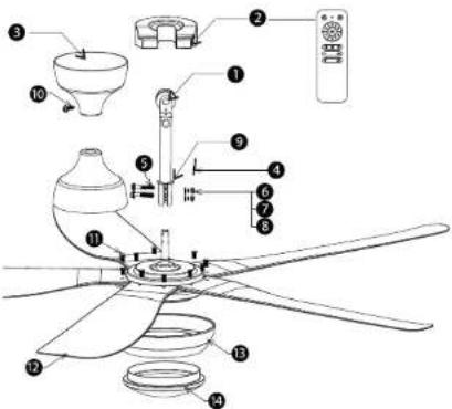
* Pictures are for illustration purpose only.
2
3
Specifications
| Model | CF56DC3RL | CF56DC4RL |
| Blade Size | 56" | 56" |
| Blade Material | ABS | ABS |
| Number of Blades | 5 | 5 |
| Motor | 153mm x 12mm DC Motor | 153mm x 12mm DC Motor |
| Voltage | 220-240V - 50/60Hz | 220-240V - 50/60Hz |
| Power | 56W (Fan: 38W; LED: 18W) | 56W (Fan: 38W; LED: 18W) |
| Noise Level | 54.8dB | 54.8dB |
| Power Consumption | Low: 4W High: 28W | Low: 4W High: 28W |
| Fan Speed | Low: 93rpm High: 209rpm | Low: 93rpm High: 209rpm |
| Air Delivery | 187.68m3/min; 6627CFM | 187.68m3/min; 6627CFM |
| Coverage Area | 25-30m2 | 25-30m2 |
| Net Weight | 4.9kg | 4.9kg |
| Speed Setting | 6-Speed | 6-Speed |
| Mounting System | Ceiling Hook (U Hook) | Ceiling Hook (U Hook) |
| LED Light Kit | 18W LED | 18W LED |
| LED Colour | Day Light / Warm Light / Natural White | Day Light / Warm Light / Natural White |
| Remote Control | RF Remote Control | RF Remote Control |
| Product Dimension | 150 x 290 x 1390mm | 150 x 290 x 1390mm |
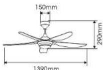
* Specifications are subject to change without prior notice.
Installation Instructions
WARNING: TURN OFF THE MAIN SWITCH AT THE DB (ELECTRICAL DISTRIBUTION BOX)
STEP 1
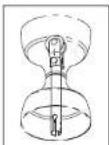
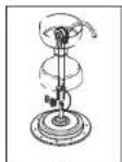
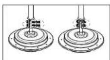
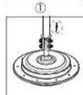
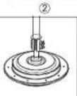
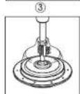
Install Down Rod Set
-
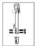
Release the 3 Hexagon Bolts and plastic sleeve (as shown) of the Downrod.
-
Insert 2 canopies to the Downrod. (as shown)
-
Assemble the downrod to the motor shaft and align all holes. Make sure to insert the plastic sleeve back and all wires from motor through the Downrod.
-
Assemble back all the opened Hexagon bolts and fix back the Cotter Pin.
- Place the canopy on the top plastic sleeve.
- Fix back the 2 screws onto the Motor Shaft then the Downrod assembly is complete.
STEP 2
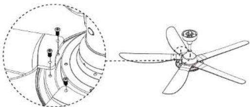
Mounting the Blades.
Align the holes to the motor. Fasten it with screws provided.
natural_image
Technical line drawing of a propeller with internal components and a close-up inset showing the blade structure (no text or symbols)STEP 3
a) Assemble the Ceiling fan to the ceiling hook (U Hook).
Remove the Cotter pin, nut, flat washer, spring washer, bolt and the rubber wheel from the downrod. Place the rubber wheel to the ceiling hook and place back the bolt, flat washer, spring washer, nut and insert the cotter pin after securely fastening them.
WARNING: COTTER PIN MUST BE INSERTED TO PREVENT THE NUT FROM LOOSENING!
b) Connect the Power wires to ceiling fan connector.
Connect the Power cord's Blue wire to N (Neutral), Brown wire to L (Live) and Yellow/Green wire to E (Earth) on the connector. Make sure all the wires colour is the same as the other side of the connector.
4
STEP 4
Connect Safety Cable to the Ceiling Hook.
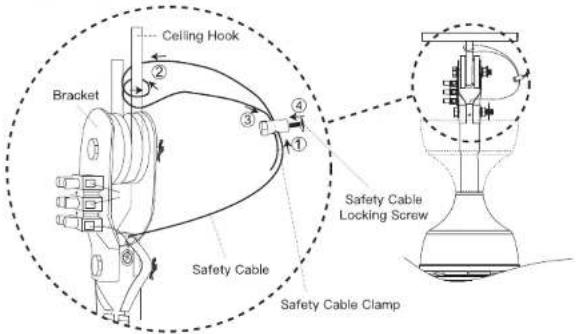
- Slide Safety Cable Clamp onto Safety Cable from fan.
- Place the end of Safety Cable through the loop of the ceiling hook.
- Slide end of Safety Cable through the hole of Safety Cable Clamp.
- Tighten it with Safety Cable Locking Screw.
WARNING: MAKE SURE THE CEILING HOOK IS FIRMLY FIXED TO THE CONCRETE CEILING!
| WARNING | |
| Hook must withstand 10 times the ceiling fan weight.Plug the cotter pin into the bolt and bend the cotter pin. | |
STEP 5
Remote Control Connection.
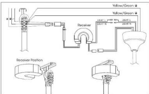
STEP 6
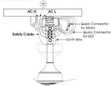
Wire Connection.

Make sure power is OFF before attempting installation.
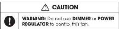
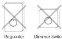
WARNING: FAILURE TO DISCONNECT POWER SUPPLY PRIOR TO INSTALLATION MAY RESULT IN SERIOUS INJURY.
STEP 7
Assemble the LED Light and LED Light Cover.
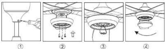
- Lock the top canopy in the correct position. (as shown in figure 1)
-
Tighten the three screws on the LED Light plate. (as shown in figure 2)
-
Connect the connector together with the LED wires. (as shown in figure 3)
- Place the LED Light Cover to the LED Light. (as shown in figure 4)
Remote Control & Operation
Battery Compartment
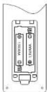
Battery Type: 2 pieces of leak-proof UM4(AAA) battery (1.5V)
Remote Control (back view)
Remote Control Buttons
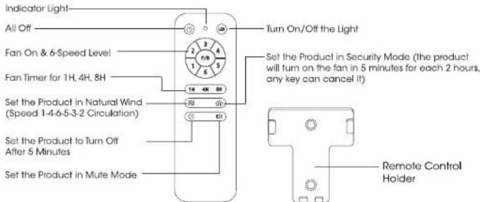
Remote Control Pairing Steps & Troubleshooting
- Make sure the power is turned off, turn off the main power button and then turn it on again.
- Use the remote control to aim on the ceiling fan, and push the " Ⓤ" button and hold for a few seconds.
- And you will hear "Dee Dee" sound, this means remote control is connecting with receiver, then you can start to use it as usual.
- If not, you can try again until you hear the alarm sound.
Balancing Kit
Your ceiling fan may be unstable when it is first fitted due to an irregularity in the blades or blade brackets. This may also occur due to improper assembly of the blades or mounting bracket.
The following procedure outlines how to rectify such problems:
- Ensure that all blades are firmly secured to the blade brackets.
- Ensure that all blades are firmly secured to the fan body and the pitch of the blades are all equal.
- From below the fan, visually inspect the blades and ensure none of them are bent or out of line. If you notice a blade is not in the right position or pitch, gently bend the blade holder to the correct position.
- If the fan is still unstable, the tracking of the blades must be checked. Using a tape measure, measure the distance from the leading edge of the blade to the ceiling. Ensure this is the same for all blades and make any minor adjustments by gently bending the blade holder if this is off.
If by following all the above steps your fan is still unstable, then the dynamic blade balancing kit must be used.
- Turn the fan on and adjust to the highest speed setting.
- Tum the fan off, select a blade and place the balancing clip onto it, halfway between the tip of the blade and the end of the blade.
• Turn the fan on and observe if the wobble has improved. - Repeat this step on all of the blades and make a note which blade boosted the greatest improvement.
- Place the clip back onto this blade & move up and down the length of the blade until you are happy that you have found a spot that reduces the wobble.
• Install a balancing weight in this spot, ensuring you place the weight on the top face of the blade along the center line. You may need to use a sharp knife to separate the weights. - Turn the fan on and check that it is now stable & operates fine.
CAUTION! : Stay clear of moving blades. If the clip is not secure on the blade for any reason, turn the fan off immediately. This could result in injury.
安全注意事项
安全和警告信息
natural_image
Technical line drawing of a propeller assembly with mounting holes and internal components (no text or symbols)步骤3
a)将吊扇安装到挂钩(U钩)上。
natural_image
Technical diagram of a propeller assembly with labeled parts and exploded view (no text or symbols present)LANGKAH 3
a) Pasang Kipas Siling ke cangkuk siling (U Hook).
- IMPORTANT
- Safety Precaution Information
- Safety & Warning Information
- Cleaning & Maintenance
- Parts Identification
- Installation Instructions
- STEP 1
- STEP 2
- STEP 3
- STEP 4
- STEP 5
- STEP 6
- STEP 7
- Remote Control & Operation
- Remote Control Pairing Steps & Troubleshooting
- Balancing Kit
- 安全注意事项
- 安全和警告信息
- LANGKAH 3
Brand : Khind
Model : CF56DC4RL
Category : Household Fan