CF683DC - Ventilateur domestique Khind - Free user manual and instructions
Find the device manual for free CF683DC Khind in PDF.


User questions about CF683DC Khind
0 question about this device. Answer the ones you know or ask your own.
Ask a new question about this device
Download the instructions for your Ventilateur domestique in PDF format for free! Find your manual CF683DC - Khind and take your electronic device back in hand. On this page are published all the documents necessary for the use of your device. CF683DC by Khind.
USER MANUAL CF683DC Khind
USER MANUAL
SERIAL NO.:
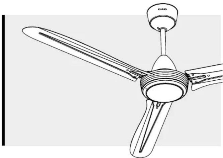
60" BLDC CEILING FAN
CF683DC
natural_image
Line drawing of a three-blade propeller with a knob and top handle (no text or symbols)KHIND CARE Mobile App


Download to register for E-Warranty & enjoy hassle-free after-sales services.
1-800-88-0032
khind.com.my

IMPORTANT
Please read this manual carefully before operating this product. Keep this manual handy for further reference.
P/N: 40-12394-06
CAUTION
- This appliances is not intended for use by person (including children) with reduced physical, sensory or mental capabilities, or lack of experience and knowledge, unless they have been given supervision or instruction concerning use of the appliance by a person responsible for their safety. Children should be supervised to ensure that they do not play with the appliance.
2.
WARNING
If unusual oscillating movement is observed, immediately stop using the fan and contact the manufacturer, its service agent or suitably qualified persons.
- It is recommended to examine the fan suspension system for at least once in every years.
- Do not attempt to repair fan. Always return fan to our authorised service agent for repair.
- Safety wire & mounting hook must be able to withstand 10 times the weight of ceiling fan. (Product net weight: 5.2kg)
- That the mounting of the suspension system shall be performed by the manufacturer, its service agent or suitably qualified person.
- To reduce the risk of injury to person, install fan at least 2.5m(8.3ft) above the ground and 1 meter from the nearest wall.
- This appliance must be earthed.
- Do not use any other down rod expect provided by KHIND. This is to ensure good performance and extra protection.
- The double poles single throw switch must have a contact separation of at least 3mm must be incorporated in the fixed wiring.
- Disconnect power supply before dismantling any part for cleaning.
- For household use only, not intended for any business purposes.
- Do not use in hot or wet environment or near to flammable materials.
- The wires in these power supply leads are coloured in accordance with the following codes. (Green/Yellow-Earth(E), Blue-Neutral(N), Brown-Live(L).
- If the power supply lead is damaged, it must be replaced by an authorized service agent or the manufacturer to avoid any hazard.
WARNING
- Ceiling Fan must be mounted above 2.5m from the floor and 1m from the wall to the Blade. Avoid fixing inside the dome ceiling.
- Ensure Downrod has been fully tigthen to Motor Shaft.
(Bold tightening torque is 800\~1000 N.cm)
Can cause injury if ceiling fan drops.
- R Cotter Pin must fix into Bolt as shown. Can cause injury if Ceiling Fan drops.

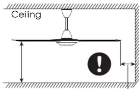
More than 2.5m More than 1m
Cleaning & Maintenance
- Keep the fan blade clean & use it at dry place. Do not bend the blades when installing & maintaining.
- Wipe away dirt until dry with clean soft cloth, soap & water to clean the fan. Do not use solvents such as gasoline or petroleum.
Operating Instruction
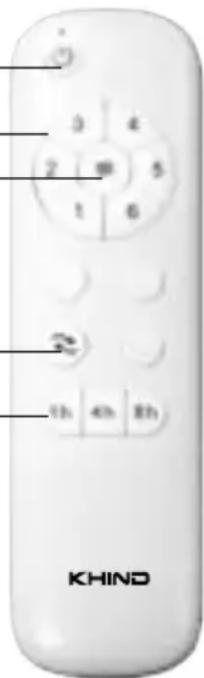
1. ON/OFF Button
Press the ON/OFF Button on the remote to start/stop the fan operation. (Default speed 3 - Forward condition - Normal Wind).
2. Speed Button
Press the Speed Button (1,2,3,4,5,6) to select desired speed.
3. Natural Button
Press the Natural Button for fan operate on natural wind. To back on normal wind, switch off & turn on back the fan.
4. Forward/Reverse Button
Press the Forward/Reverse Button for fan operate on forward or reverse rotation.
5. Timer Button
Press Timer Button (1h/4h/8h) to set timer function. Switch off the fan operation to cancel timer function.
\*Battery
The remote control is operated by 2 standard AAA 1.5V batteries.
ON/OFF Button ____
Speed Button —
Natural Button
Forward/Reverse
Button
Timer Button ____
Note
1. Pairing Remote Control With Fan Unit.
Pairing code matching mode is used between the Remote Control and Receiver. Turn "ON" the supply power within 30 seconds and press the ON/OFF button for 5 seconds. It can load normally after hearing the long sound "bep", which means pairing is successful, and it can work normally. (Note: Pairing mode is not accepted after turning "ON" the supply power for 30 seconds.)
After installation, it can be used directly. If you want to add or replace a new Remote Control, you need to pair it again.
2. If the Remote Control unable to remotely control the Receiver:
- Please check whether the switch batteries are in good control. Whether they are fixed properly and whether they run out of use.
or
- Please check is there any existence of similar remote controlled products nearby, then check whether they works, because remote controlled product with the same frequency will disturb each other.
- Low voltage of battery will affect the sensitivity of the Remote Control and the signal reception accordingly, must replace if the battery is getting low voltage.
- Please take out the battery from the Remote Control when leaving unused for long time.
3
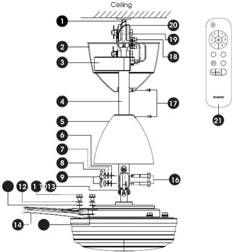
Parts Identification
- Ceiling Hook
- Top Canopy
- Receiver
- Downrod
- Bottom Canopy
- Flat Washer
- Spring Washer
- Hex Nut
- R Cotter Pin
- Earth Wire
- Screw M6
- Spring Washer
- Flat Washer
- Fan Blade
- Underlay
- Bolt M8
- Screw M3.5
- Terminal Block
- Rubber Wheel
- Safety Wire
- Remote Control
Installation Method
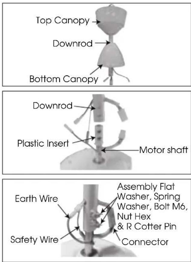
-
Insert the Top Canopy and then follow with the Bottom Canopy to the Downrod.
-
Insert the Plastic Insert and then insert the Downrod into the Motor shaft.
-
Assemble the R Cotter Pin, Bolt M6, Nut Hex, Flat Washers, and Spring Washers from the accessories pack provided to the Downrod. Ensure the Bolt M6 and R Cotter Pin are fixed firmly. Connect the Motor and Earth Wire connector, then fix the Safety Wire to the Motor Shaft.
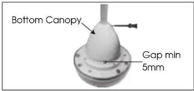
- Move down the Bottom Canopy to cover the Downrod and Motor shaft assemblies. Ensure there is a gap of at least 5mm between the Bottom Canopy and the Motor, and then fix it by tightening the provided Screw M3.5.
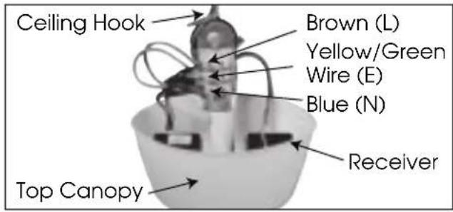
- Connect the connector wire to the Receiver as per shown on the diagram.
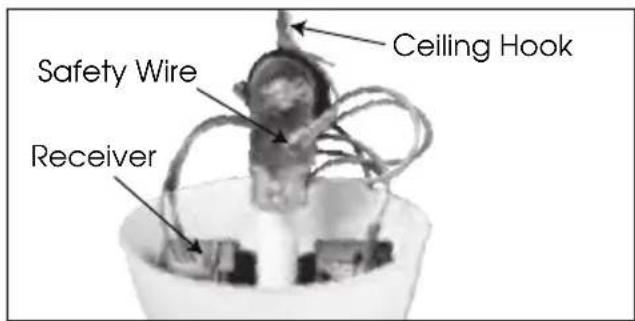
- Fix the Safety Wire to the Bracket with the screw provided after wrapping the Safety Wire twice around the Ceiling Hook.
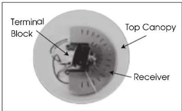
- Make sure driver position as per diagram to get better wire arrangement. Then push up the Top Canopy and fix it using provided Screw M3.5. Ensure there was min gap 5mm between Top Canopy and Ceiling.
Install Blade to Motor
natural_image
Abstract geometric pattern with intersecting diagonal lines and a numbered circle (8) in the top-left corner, no text or symbols present.
natural_image
Close-up of a white cylindrical object with a black checkmark below it (no text or symbols visible)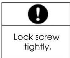
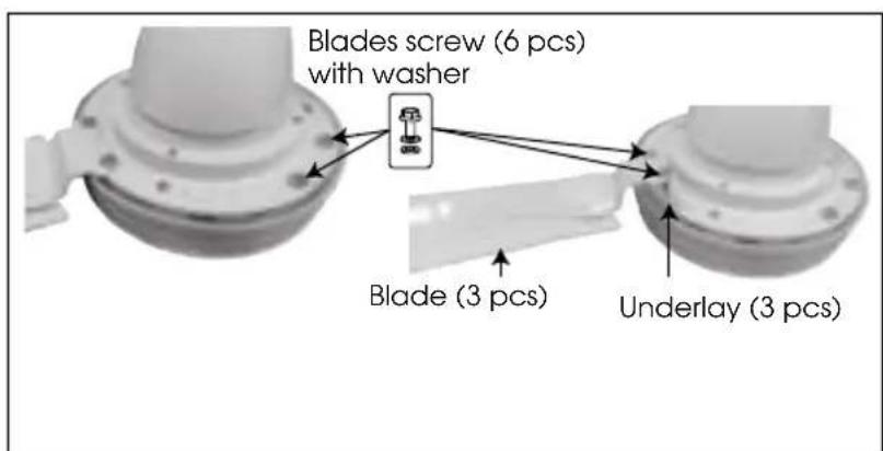
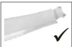
- Remove blade screw (6 pcs) of the motor unit. Install the fan blades properly, make sure the underlay is also fitted between the blades and the motor unit and tighten the screw.
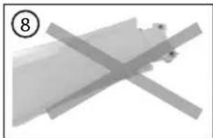
- Do not fix the blade at the position as shown in the figure 8. Can cause no air flow.

flowchart
graph LR
    A["DC MOTOR"] --> B["Red"]
    A --> C["Gray"]
    A --> D["PINK"]
    A --> E["GREEN/YELLOW"]
    B --> F["RECEIVER"]
    C --> F
    D --> F
    E --> F
    F --> G["BROWN"]
    F --> H["GREEN/YELLOW"]
    F --> I["BLUE"]
    G --> J["Terminal Block"]
    H --> J
    I --> J
    K["ACL"] --> J
    L["E"] --> J
    M["ACN"] --> J
Ensure that the wiring follow the wiring diagram as shown.
Connecting to the Power Supply
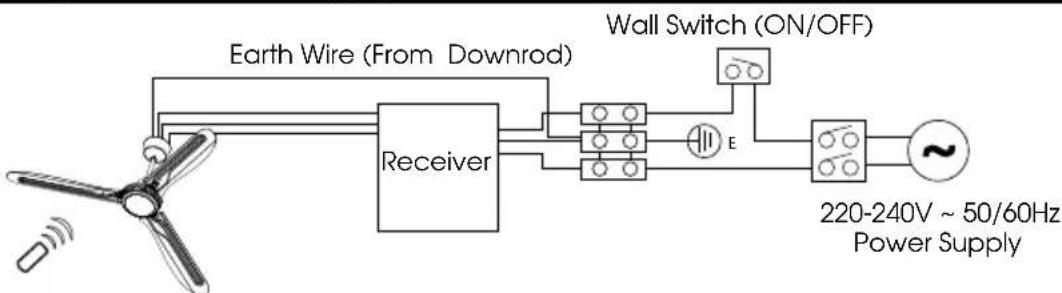
flowchart
graph LR
    A["Fan"] --> B["Receiver"]
    B --> C["Wall Switch (ON/OFF)"]
    C --> D["Power Supply"]
    B --> E["Earth Wire (From Downrod)"]
    E --> B
    C --> F["220-240V ~ 50/60Hz Power Supply"]
Final Confirmation
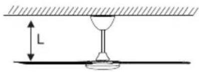
Measure the distance using a measuring tape. Please adjust all the Blades to get the equal distance from ceiling to the Blade Tip, L (within 1 mm tolerance).

CAUTION
After installation make sure the Ceiling Fan does not wobbles extremely. Can cause injury if Ceiling Fan drops.
Check Point Installation
To ensure safety, kindly check the following.
- The ceiling fan is securely fixed to the main hook.
- Safety wire is securely fixed and tightened by screw.
- The wiring between power supply and ceiling fan is connected properly and correctly.
- Make sure all screws to secure the plastic covers are tightened properly.
- The screws for securing fan blade are tightened properly.
- Snap pins and nuts provided are inserted and tightened properly.
Specifications
| Model | CF683DC | |||
| Voltage | 220-240V | ~ | 50/60Hz | |
| Power | 40W | |||
| Fan Size | 60" (1500mm) | |||
| Net | Weight | 5.2kg | ||
| Max Speed (RPM) | 210 | |||
* Specifications are subject to change without prior notice.
AWAS
natural_image
Pure electrical circuit lines without any symbols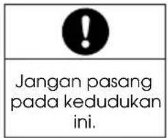
natural_image
Close-up of a white cylindrical object with a black checkmark mark below it (no text or symbols visible)
- 60" BLDC CEILING FAN
- IMPORTANT
- CAUTION
- WARNING
- Cleaning & Maintenance
- Operating Instruction
- ON/OFF Button
- Speed Button
- Natural Button
- Forward/Reverse Button
- Timer Button
- \*Battery
- Note
- Pairing Remote Control With Fan Unit.
- If the Remote Control unable to remotely control the Receiver:
- 3
- Parts Identification
- Installation Method
- Final Confirmation
- Check Point Installation
- AWAS
Brand : Khind
Model : CF683DC
Category : Ventilateur domestique