IC2.2 - Home trainer INSPIRE - Free user manual and instructions
Find the device manual for free IC2.2 INSPIRE in PDF.


| Brand | Inspire |
| Model | IC2.2 |
| Product Type | Indoor Cycling Bike (Home Trainer) |
| Dimensions (L x W x H) | Approx. 48 x 21 x 40 inches (122 x 53 x 102 cm) |
| Weight | Approx. 85 lbs (38.5 kg) |
| Max User Weight | 300 lbs (136 kg) |
| Flywheel Weight | 40 lbs (18 kg) |
| Resistance System | Magnetic, with infinite adjustment |
| Power Source | Self-powered (no electrical outlet required) |
| Display Console | LCD screen showing time, distance, speed, calories, heart rate (if compatible) |
| Pedals | Dual-sided SPD compatible / Toe cages |
| Seat Adjustment | Vertical and horizontal |
| Handlebar Adjustment | Vertical and horizontal |
| Transport Wheels | Yes, for easy mobility |
| Water Bottle Holder | Yes |
| Heart Rate Monitor | Wireless receiver (chest strap optional) |
| Maintenance | Periodic lubrication of chain, check bolts tightness, clean with damp cloth |
| Safety Features | Emergency brake (push down on flywheel), stable frame, non-slip pedals |
| Replacement Parts | Available via Inspire customer service: seat, pedals, belt, console |
| Warranty | Frame: Lifetime, Parts: 2 years, Labor: 1 year |
| Assembly Required | Yes, simple assembly with included tools |
Frequently Asked Questions - IC2.2 INSPIRE
User questions about IC2.2 INSPIRE
0 question about this device. Answer the ones you know or ask your own.
Ask a new question about this device
Download the instructions for your Home trainer in PDF format for free! Find your manual IC2.2 - INSPIRE and take your electronic device back in hand. On this page are published all the documents necessary for the use of your device. IC2.2 by INSPIRE.
USER MANUAL IC2.2 INSPIRE
NOTE: Please read all instructions carefully before using this product.
Table of Contents Safety Notice Hardware Identifier Assembly Instructions Parts list Exploded Diagram Warranty
MODEL IC 2.2
Retain This Manual for Reference
10-2016
OWNER'S MANUAL

natural_image
Abstract gray circular design with overlapping rings (no text or symbols)INSPIRE
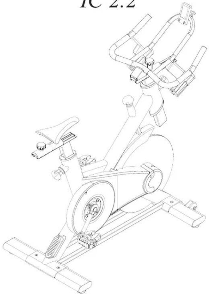
Indoor Cycle IC 2.2
natural_image
Line drawing of an outdoor stationary bike with visible frame and wheels (no text or symbols)255 Airport Cir., Corona, CA 92880 Tel:(877) 738-1729 Fax: (714) 738-1728 www.inspirefitness.com
Table of Contents
Before You Begin 2
Important Safety Notices .... 3
Warning Label Placement 4
Contents of Packaging 5
Hardware Pack 6
Assembly Instructions....7-11
Wireless Console Installation 12
Maintenance....13
Parts List 14-15
Exploded Diagram 16
Warranty 17
Before You Begin
Thank you for selecting the INSPIRE INDOOR CYCLE. For your safety and benefit, read this manual carefully before using the machine. As a manufacturer, we are committed to providing you complete customer satisfaction. If you have any questions, or find there are missing or damaged parts, please call our TOLL-FREE customer service number. Our Customer Service Agents will provide immediate assistance to you.
IMPORTANT SAFETY NOTICE
PRECAUTIONS
This exercise machine is built for optimum safety. However, certain precautions apply whenever you operate a piece of exercise equipment. Be sure to read the entire manual before you assemble or operate your machine. In particular, note the following safety precautions:
- Keep children and pets away from the machine at all times. DO NOT leave children unattended in the same room with the machine. The mechanism on this machine can cause serious injury or death if used improperly.
- Never place your hands or feet in the path of the pedals because injury may occur to you or damage may occur to the equipment. Never allow children to come near or approach the moving pedals while in use.
- If the user experiences dizziness, nausea, chest pain, or any other abnormal symptoms, STOP the workout at once. CONSULT A PHYSICIAN IMMEDIATELY.
- Position the machine on a clear, leveled surface. DO NOT use the machine near water or outdoors.
- Keep hands away from all moving parts.
- Always wear appropriate workout clothing when exercising. DO NOT wear robes or other clothing that could become caught in the machine. Running or aerobic shoes are also required when using the machine.
- Use the machine only for its intended use as described in this manual. DO NOT use attachments not recommended by the manufacturer.
- Do not place any sharp objects around the machine.
- Disabled persons should not use the machine without a qualified person or physician in attendance.
- Before using the machine to exercise, always do stretching exercises to properly warm up.
- Never operate the machine if the machine is not functioning properly.
- Maximum user weight 300 lbs.
CARE AND MAINTENANCE
- Keep seat and handlebar sliders clean.
- Lubricate the adjustment tubes by spraying a coat of WD40 and wiping it off, monthly.
- Inspect and tighten all parts before using the machine.
- The Frame and Seat Pad of the machine can be cleaned using a damp cloth and mild non-abrasive detergent. DO NOT use solvents.
WARNING: BEFORE BEGINNING ANY EXERCISE PROGRAM, CONSULT YOUR PHYSICIAN. THIS IS ESPECIALLY IMPORTANT FOR INDIVIDUALS OVER THE AGE OF 35 OR PERSONS WITH PRE-EXISTING HEALTH INSTRUCTIONS BEFORE USING ANY FITNESS EQUIPMENT. Neither Health In Motion, LLC. nor FG1, LLC. ASSUMES ANY RESPONSIBILITY FOR PERSONAL INJURY OR PROPERTY DAMAGE SUSTAINED BY OR THROUGH THE USE OF THE PRODUCT.
Warning Label Placement
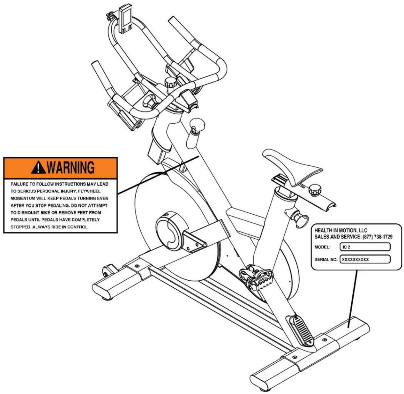
The warning label has been placed on the unit at the location shown. If the label is missing or illegible, please call customer service at 1-877-738-1729 for replacements. Apply the labels in the locations shown.
Contents of Packaging
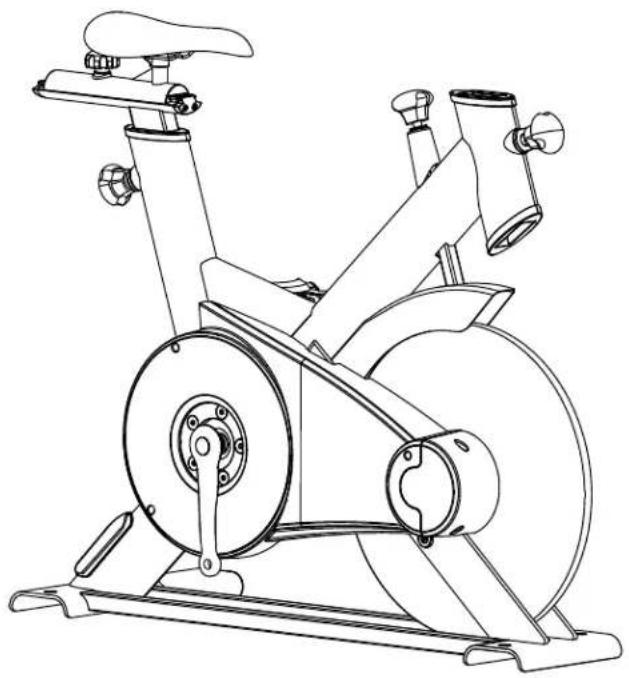 | 1 | 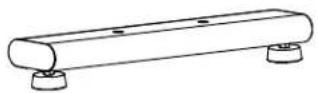 | 1 |
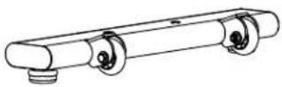 | 1 | ||
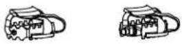 | 1 | ||
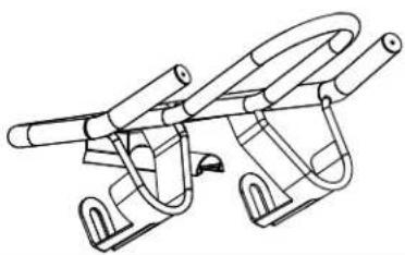 | 1 | 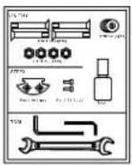 | 1 |
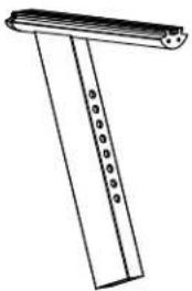 | 1 |
Hardware Pack
STEP1&2
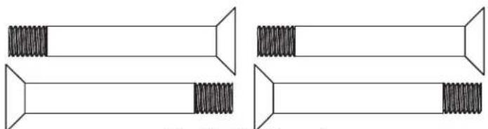
natural_image
Four identical mechanical components with threaded end caps, shown from different angles (no text or symbols)Part# 39 (4pcs)
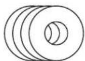
Part# 42 (4pcs)

natural_image
Four identical hexagonal nut icons arranged horizontally (no text or symbols)Part# 43 (4pcs)
STEP3
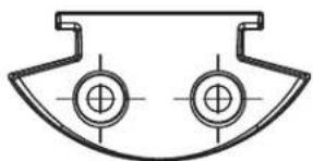
natural_image
Pure technical diagram of a symmetrical mechanical component with two circular holes (no text or symbols)Part# 30 (1pcs)


Part# 31(2pcs)
natural_image
Simple line drawing of a bottle with a vertical striped cap on top (no text or symbols)1pcs
TOOL
natural_image
Pure geometric line drawing of two L-shaped pipes without any text, numbers, or symbols
natural_image
Line drawing of a double-ended wrench with two flanges (no text or symbols)NOTE: The following parts are not drawn to scale. Please use your own ruler or scale to measure components.
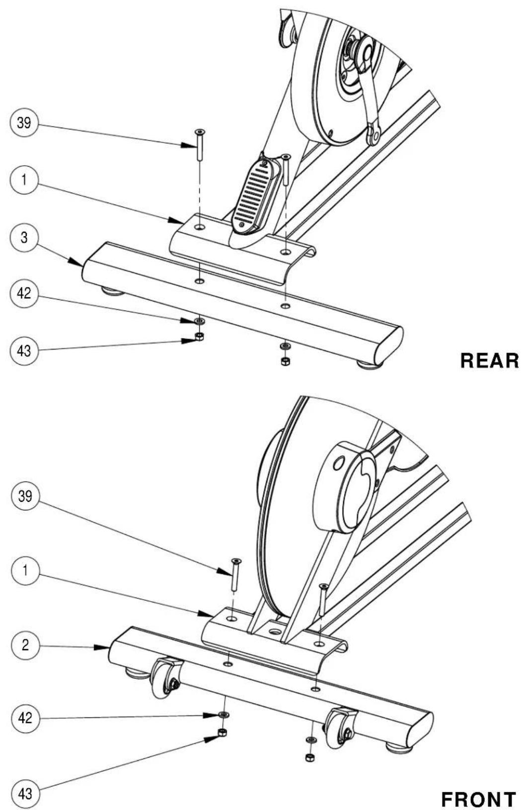
Step 1
A Install the Rear Stabilizer (3) onto the Main Frame (1) using 2-M8 Bolts (39), 2-M8 Washers (42), and 2-M8 Nuts (43).
B Install the Front Stabilizer (2) onto the Main Frame (1) using 2-M8 Bolts (39), 2-M8 Washers (42), and 2-M8 Nuts (43).
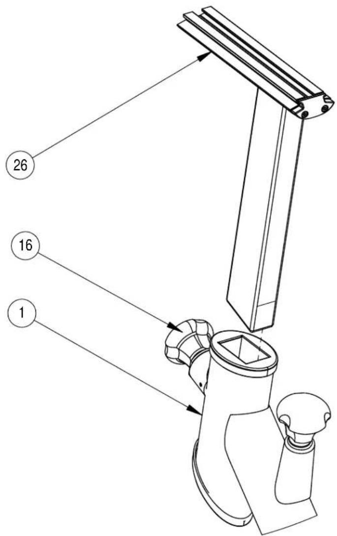
Step 2
A Insert the Handlebar Post (26) into the front of the Main Frame (1).
B Lock down or loosen the Handlebar Post (26) by threading the Pop Pin (16).
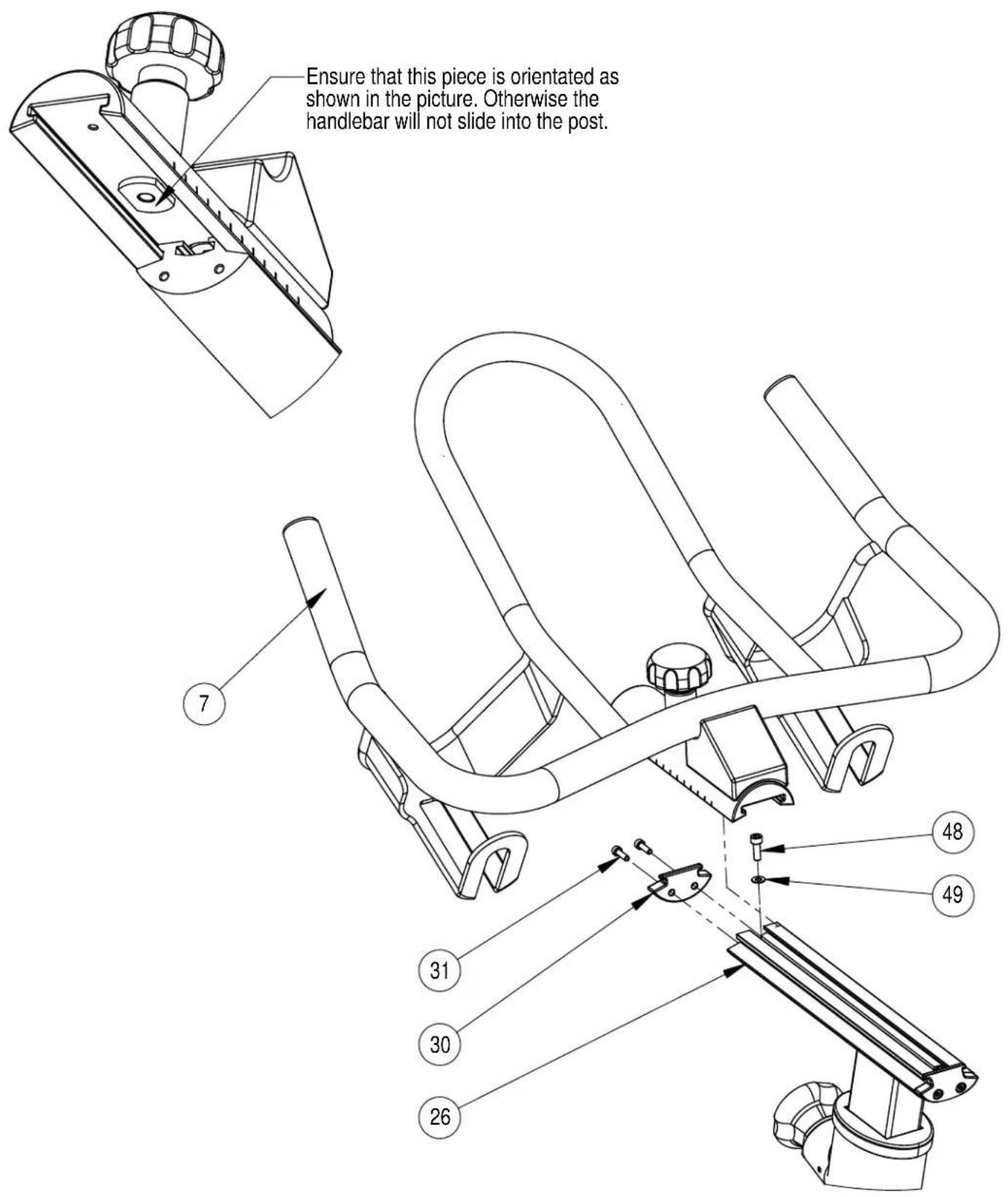
Step 3
A Remove the front M5 stop screw (48) and washer (49) from the Handlebar Post (26). Insert the Handlebars (7) into the Lower Handlebar Post (26).B
C Reinstall the front M5 stop screw (48) and washer (49) onto the Handlebar Post (26). Attach the Handlebar Slider End Cap (30) using 2-M4 Bolts (31).D
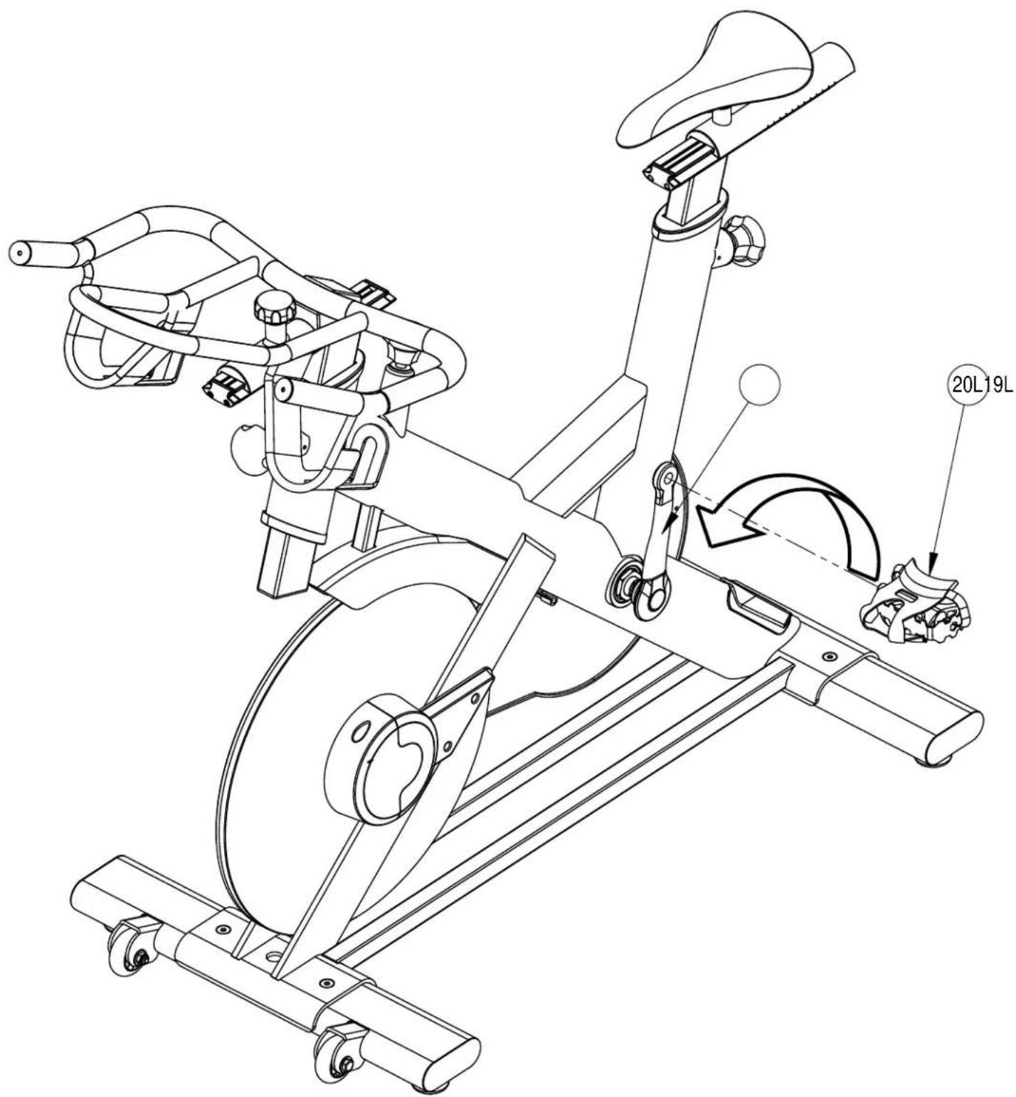
Step 4
A Attach the Left Pedal (20L) to the Left Crank (19L). Turn the threads COUNTERCLOCKWISE to install the Left Pedal(20L).
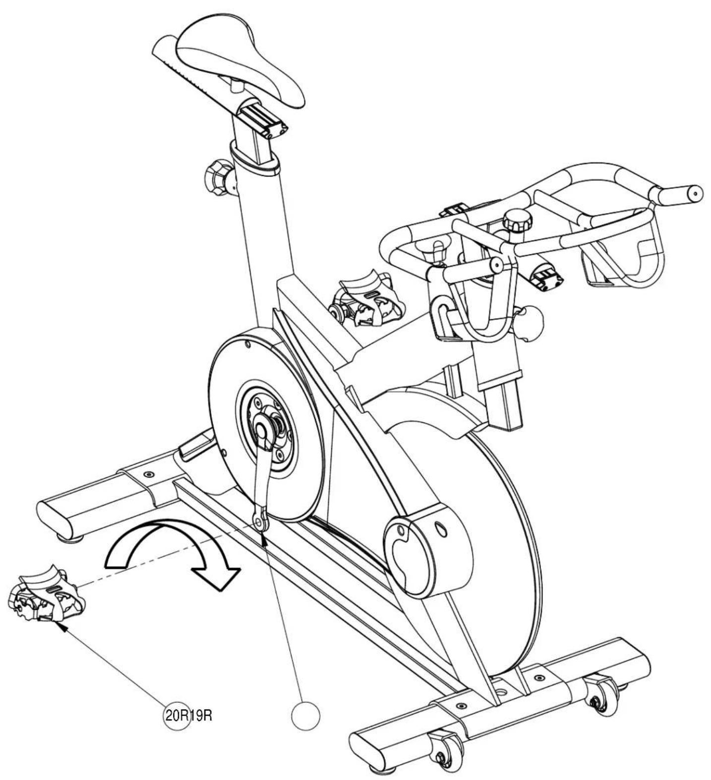
Step 5
A Attach the Right Pedal (20R) to the Right Crank (19R). Turn the threads CLOCKWISE to install the Right Pedal(20R).
IC2 Wireless Console Installation
Wireless console sold separately. Call us at 1-877-738-1729.
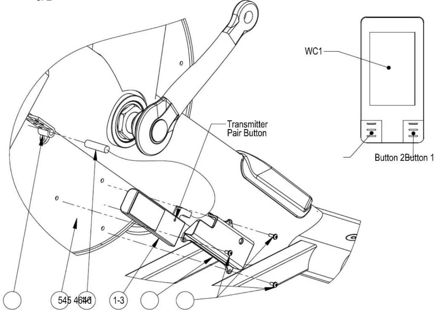
Insert the wireless transmitter (1-3) into the transmitter holster (46) making 1. sure that the orientation of the transmitter is installed as shown in the diagram below.
Secure the transmitter holster (46) to the rear shroud (5) using 3 - M3 screws 2. (46).
Insert the speed sensor (1-1) into the speed sensor bracket (45). 3.
Plug the speed sensor (1-1) into the wireless transmitter (1-3) jack.4.
Tighten the speed sensor bracket (45) to lock it into place. Test the speed 5. sensor by rotating the crank and checking if console detects speed. If it does not, push the speed sensor (1-1) in towards the right side of the bike.
NOTE: The speed sensor must be inserted far enough into the shroud that the computer can pick up the signal consistently, but not too far in that the speed sensor gets hit by the pulley behind the shroud.
Pairing Transmitter to Console.
On the console, press and hold Button's 1 & 2 at the same time for 3 seconds.1.
Press and hold the pair button on the transmitter for 5 seconds.2.
If successful, the console will display a "0" on the screen.3.
If it fails, the console will display "Err" on the screen. If this occurs, redo steps 1 4. & 2
PAGE 12
Maintenance
Monthly Maintenance
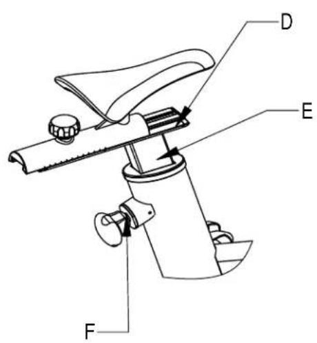
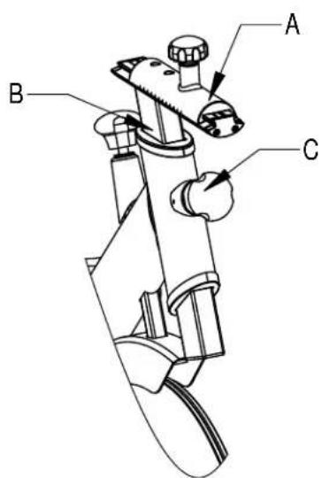
The adjustment tubes should be lubricated monthly to ensure smooth 1. adjustability. Raise the Seat Post and Handlebar Post to their highest positions. Apply WD40 or a similar spray lubricant at locations A, B, D, and E. Rub the lubrication with a soft cloth. Unthread the pop pins shown at C and F on the picture. Lubricate the threads and wipe off any excess spray.
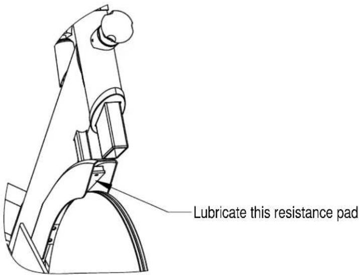
Apply lubrication to the resistance pad. We recommend using 3-in-1 Oil to 2. lubricate the leather pad. Do NOT use any lubrication containing silicone. Make sure the brake pad is thoroughly oiled from end to end. Wipe off any excess oil.
Parts List
| Item # | Part No. | Description Qty | ||
| 1 BC | 497-200-000 | Main Frame Weldment 1 | ||
| 2 BC | 497-330-002PZ | Front Stabilizer 1 | ||
| 3 BC | 497-330-001PZ | Rear Stabilizer 1 | ||
| 4 BC | 496-561-003PZ | Flywheel Assembly 1 | ||
| 5 | BC497-881-007PZ | Inner Shroud 1 | ||
| 6 | BC497-881-001PZ | Outer Shroud 1 | ||
| 7 BC | 497-881-008 | Handle Bar | 1 | |
| 8 BC | 497-560-001 | Seat Post Weldment | 1 | |
| 9 BC | 497-560-002PZ | Seat Post Free Rail | 1 | |
| 10 | BC495-401-001A | Seat Pad | 1 | |
| 11 | BC497-561-003 | Friction Plate Housing Nut | 2 | |
| 12 | BC497-881-011PZ | Seat Lock Knob Assembly | 1 | |
| 13 | BC496-881-003PZ | Resistance Assembly Dial | 1 | |
| 14 | BC495-801-005PZ | Flywheel Shroud | 1 | |
| 15 | BC497-881-012PZ | Upper Plastic Sleeve | 2 | |
| 16 | BC497-881-009 | Pop Pin | 2 | |
| 17 | BC497-561-011 | Friction Plate 2 | ||
| 18 | BC495-881-002PZ | Resistance Pad Assembly | 1 | |
| 19L | BC850-561-012 | Crank Pedal, L 1 | ||
| 19R BC | 850-561-002 | Crank Pedal, R 1 | ||
| 20L | BC495-340-001L | Pedal, L | 1 | |
| 20R | BC495-340-001R | Pedal, R | 1 | |
| 21 | 0111-208-251 | Hex Flanged Bolt | 2 | |
| 22 | 0111-012-509PZ | Idler Assembly | 1 | |
| 23 | BC496-561-004PZ | Belt Tensioning Assembly | 2 | |
| 24 | BC496-561-007 | Belt | 1 | |
| 25 | BC497-881-004PZ | Left Shroud Cap 1 | ||
| 26 | BC497-560-003 | Handlebar Post Weldment | 1 | |
| 27 01 | 10-412-599 Hex Flange Nut 2 | |||
| 28 BC | 20-221-41 Plastic Cap 2 | |||
| 29 BC | 497-881-003PZ Shroud, L 1 | |||
| 30 BC | 497-881-005 Adjustable Rail End Cap 4 | |||
| 31 01 | 13-204-109 Hex Bolt 8 | |||
| 32 BC | 495-881-013APZ Lower Plastic Sleeve 1 | |||
| 33 BC | 496-561-010APZ Crankshaft Assembly 1 | |||
| 34 02 | 00-300-086 Crankshaft Bearing 2 | |||
| 35 BC | 497-561-005 Crankshaft Bearing Spacer 1 | |||
| 36 BC | 497-881-002PZ Right Shroud Cap 1 | |||
| 37 BC | 496-561-014 Crankshaft Locknut 2 | |||
| 38 BC | 497-560-004PZ Handlebar Rail, Free 1 | |||
| 39 01 | 13-310-259 Hex Bolt 2 | |||
| 40 | BC497-881-006PZ Calf Stretcher 1 | |||
| 41 BC | 497-881-010PZ Handlebar Adjustment Knob 1 | |||
| 42 01 | 16-008-009 Flat Washer 4 | |||
| 43 | 0110-708-029A Lock Nut 4 | |||
| 44 BC | 497-891-002PZ Hardware Pack 4 | |||
| 45 BC | 770-801-011PZ Speed Sensor Bracket 1 | |||
| 46 BC | 497-881-015PZ Wireless Transmitter Holster 1 | |||
| 47 | WC1 Wireless Console Unit 1 | |||
| 48 01 | 13-205-170 M5 Hex Screw 4 | |||
| 49 01 | 16-005-010 M5 Washer 4 | |||
Exploded View
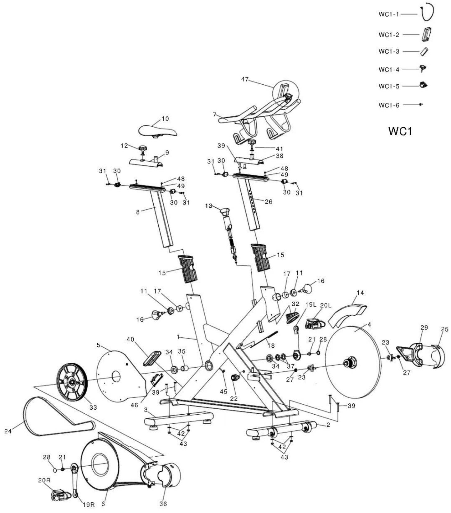
INSPIRE
Warranty
This Warranty applies to Inspire Cardio products manufactured or distributed by Inspire Fitness LLC.
| R | E | S | I | D | E | N | T | I | A | L | W | A | ||
| 10 YEAR FRAME: | 5 YEAR FRAME: | |||||||||||||
| I | n | c | l | u | d | e | s | M | a | i | n | F | ||
| 3 | Y | E | A | R | P | A | R | T | S | : | ||||
| Main Axle Bearings, Main Axle, Main Pulley, Idler Bearings,Flywheel Bearings, Cranks, Flywheel, Handlebar Post,H | a | n | d | l | e | b | a | r | , | a | n | d | ||
| 1 | Y | E | A | R | P | A | R | T | S | : | ||||
| Seat, Grip, Handlebar, Pedal Straps, Resistance PadBelt, and Brake Assembly Belt, Brake and Assembly. | Seat, Grip, Handlebar, Pedal Straps, Resistance Pad | |||||||||||||
| 6 MONTH ACCESSORIES | 6 MONTH ACCESSORIES | |||||||||||||
| 1 YEAR PEDALS | 1 YEAR PEDALS | |||||||||||||
| I | Y | E | A | R | L | A | B | O | R | |||||
Inspire Fitness, LLC. warrants that the Product you have purchased for personal, family or household use from Inspire Fitness LLC or from an authorized Inspire Fitness reseller is free from defects in materials or workmanship under normal use during the warranty period. Your sales receipt, showing the date of purchase of the Product, is your proof of the date of purchase. This warranty extends only to you, the original purchaser. It is not transferable to anyone who subsequently purchases the Product from you. It excludes expendable parts such as paint and finish. This Warranty becomes VALID ONLY if the Product is assembled / installed according to the instructions / directions included with the Product.
Replacement and repair of parts.
During the warranty period Inspire Fitness will, at no additional charge, repair or replace the Product if it becomes defective, malfunctions, or otherwise fails to conform with this Warranty under normal personal, family, or household use. In repairing the product Inspire Fitness may replace defective parts with, at the option of Inspire Fitness, serviceable used parts that are equivalent to new parts in performance, or new parts. All exchanged parts and Products replaced under this warranty will become the property of Inspire Fitness. Inspire Fitness reserves the right to change manufacturers and or specification of any part to cover any existing warranty.
Service procedures.
To obtain warranty parts, you must return the parts to Inspire Fitness or an authorized Inspire Fitness retailer in its original container (or equivalent). You must pre-pay any shipping charges, taxes, or any other charges associated with transportation of the Product. In addition, you are responsible for insuring any Product shipped or returned. You assume the risk of loss during shipment. You must present Inspire Fitness with proof-of-purchase documents (including the date of purchase, Model, and Serial Number). Any evidence of alteration, erasing or forgery of proof-of-purchase documents will be cause to void this Warranty. Register your warranty online visit www.inspirefitness.com
Conditions and Exceptions.
This Warranty does not extend to any Product not purchased from Inspire Fitness LLC or from an authorized Inspire Fitness reseller. This Warranty does not extend to any Product that has been damaged or rendered defective; (a) as a result of accident, misuse, or abuse; (b) by the use of parts not manufactured or sold by Inspire Fitness; (c) by modification of the Product; (d) as a result of service by anyone other than Inspire Fitness, or an authorized Inspire Fitness warranty service provider; (e) product that has not been properly maintained (follow maintenance schedule found on product). Should any product submitted for Warranty service be found to be ineligible, an estimate of repair cost will be furnished and the repair will be made if requested by you upon Inspire Fitness receipt of payment or acceptable arrangement of payment.
Disclaimer
EXCEPT AS EXPRESSLY SET FORTH IN THIS WARRANTY Inspire Fitness MAKES NO OTHER WARRANTIES; EXPRESSED OR IMPLIED INCLUDING ANY IMPLIED WARRANTIES OF MERCHANTABILITY AND FITNESS FOR A PARTICULAR PURPOSE. Inspire Fitness, LLC. EXPRESSLY DISCLAIMS ALL WARRANTIES NOT STATED IN THIS WARRANTY. ANY IMPLIED WARRANTIES THAT MAY BE IMPOSED BY LAW ARE LIMITED TO THE TERMS OF THIS WARRANTY. NEITHER Inspire Fitness NOR ANY OF ITS AFFILIATES SHALL BE RESPONSIBLE FOR INCIDENTAL OR CONSEQUENTIAL DAMAGES. Inspire Fitness IS NOT RESPONSIBLE FOR THE REPAIR OR REPLACEMENT OF ANY PARTS THAT Inspire Fitness DETERMINES HAVE BEEN SUBJECTED AFTER THE DATE OF MANUFACTURE TO ALTERATION, NEGLECT, ABUSE, MISUSE, NORMAL WEAR & TEAR, ACCIDENT, DAMAGE DURING TRANSIT OR INSTALLATION, FIRE, FLOOD, OR ANY ACT OF GOD. SOME STATES DO NOT ALLOW LIMITATIONS ON HOW LONG AN IMPLIED WARRANTY LASTS OR THE EXCLUSION OR LIMITATION OF INCIDENTAL OR CONSEQUENTIAL DAMAGES, SO THE ABOVE LIMITATIONS OR EXCLUSION MAY NOT APPLY TO YOU. This Warranty gives you specific legal rights and you may also have other rights that may vary from state to state. This is the only express warranty applicable to Inspire Fitness's "Inspire" branded strength products. Inspire Fitness neither assumes nor authorizes anyone to assume for it any other express warranty.
- INSPIRE
- Table of Contents
- Before You Begin
- IMPORTANT SAFETY NOTICE
- PRECAUTIONS
- CARE AND MAINTENANCE
- Warning Label Placement
- Contents of Packaging
- Hardware Pack
- Step 1
- Step 2
- Step 3
- Step 4
- Step 5
- IC2 Wireless Console Installation
- Wireless console sold separately. Call us at 1-877-738-1729.
- Pairing Transmitter to Console.
- Maintenance
- Monthly Maintenance
- Warranty
- Replacement and repair of parts.
- Service procedures.
- Conditions and Exceptions.
- Disclaimer
Brand : INSPIRE
Model : IC2.2
Category : Home trainer